VigorTalk ATA-24 - Phone Draytek - Free user manual and instructions
Find the device manual for free VigorTalk ATA-24 Draytek in PDF.


| Product Type | Analog Telephone Adapter (ATA) / VoIP Gateway |
| Brand | DrayTek |
| Model | VigorTalk ATA-24 |
| Category | VoIP Phone Adapter |
| Dimensions (W x D x H) | Approx. 160 x 110 x 30 mm |
| Weight | Approx. 250 g |
| Power Supply | DC 12V / 1A (external adapter) |
| Ethernet Ports | 1x 10/100 Mbps RJ-45 (WAN/LAN) |
| FXS Ports | 2x RJ-11 (for analog phones) |
| VoIP Protocols | SIP (RFC3261), RTP/RTCP |
| Number of Accounts | Up to 2 SIP accounts |
| QoS | Support for DiffServ, VLAN tagging |
| Security Features | SRTP, TLS, HTTPS management |
| LED Indicators | Power, Ethernet, Link/Activity, Phone 1/2 |
| Reset Button | Yes (factory reset) |
| Operating Temperature | 0°C to 40°C |
| Maintenance | Keep clean and dry; avoid dust; periodic firmware updates |
| Safety | Use only supplied power adapter; keep away from water |
| Spare Parts | Power adapter, Ethernet cable (contact supplier) |
| Repairability | No user-serviceable parts; contact technical support |
| Warranty | Refer to DrayTek warranty policy |
| Manual | Free PDF available on notice-facile.com |
Frequently Asked Questions - VigorTalk ATA-24 Draytek
User questions about VigorTalk ATA-24 Draytek
0 question about this device. Answer the ones you know or ask your own.
Ask a new question about this device
Download the instructions for your Phone in PDF format for free! Find your manual VigorTalk ATA-24 - Draytek and take your electronic device back in hand. On this page are published all the documents necessary for the use of your device. VigorTalk ATA-24 by Draytek.
USER MANUAL VigorTalk ATA-24 Draytek
Copyright 2009 All rights reserved. This publication contains information that is protected by copyright. No part may be reproduced, transmitted, transcribed, stored in a retrieval system, or translated into any language without written permission from the copyright holders. The scope of delivery and other details are subject to change without prior notice.
Trademarks
The following trademarks are used in this document:
● Microsoft is a registered trademark of Microsoft Corp.
● Windows, Windows 95, 98, Me, NT, 2000, XP, Vista and Explorer are trademarks of Microsoft Corp.
● Apple and Mac OS are registered trademarks of Apple Inc.
- Other products may be trademarks or registered trademarks of their respective manufacturers.
Table of Contents

Preface ....1
1.1 LED Indicators and Connection 2
1.2 Hardware Installation .... 4
1.2.1 Detailed Explanation for the Connector.... 5

Configuring Basic Settings ....7
2.1 Changing Password....7
2.2 Quick Setup....9
2.2.1 Adjusting WAN Connection Mode 9
2.2.2 Static Mode....11
2.2.3 DHCP Mode.... 13

Advanced Configuration....15
3.1 System setup 15
3.1.1 Status.... 15
3.1.2 Time.... 18
3.1.3 Syslog 19
3.1.4 Access Control.... 20
3.1.5 Configuration 21
3.1.6 Firmware Upgrade 22
3.1.7 Commit....24
3.1.8 Reboot 24
3.2 Network Setup.... 27
3.2.1 WAN and Internet Access Setup 27
3.2.2 MGN 32
3.2.3 High Availability 33
3.3 Advanced Setup 34
3.3.1 Static Route Setup.... 34
3.3.2 Port Block 36
3.3.3 DDNS.... 37
3.3.4 Port Mirroring 39
3.4 Firewall Setup 40
3.4.1 DoS....40
3.5 VoIP Setup 43
3.5.1 Protocol....44
3.5.2 Port Settings 50
3.5.3 Speed Dial 52
3.5.4 Dial Plan 53
3.5.5 Tone Settings.... 55
3.5.6 Nat Traversal 57
3.5.7 Line Test 58
3.5.8 Miscellaneous 59
3.5.9 Incoming Call Barring 65
3.5.10 Statistics 67
3.5.11 Status....71
3.5.12 Call History 74
3.5.13 Configure Activate 75

Trouble Shooting....77
4.1 Checking If the Hardware Status Is OK or Not.... 77
4.2 Checking If the Network Connection Settings on Your Computer Is OK or Not 78
4.3 Pinging the Adapter from Your Computer 81
4.4 Checking If the ISP Settings Are OK or Not.... 82
4.5 Backing to Factory Default Setting If Necessary 84
4.6 Contacting Your Dealer 85
Appendix A: Telnet Commands 86
A.1 Introduction 86
A.2 Root Commands 86
A.2.1 Enter Function Commands 86
A.2.2 Other Commands 87
A.3 Advance Commands....87
A.3.1 General Commands 87
A.3.2 Port Block Commands 87
A.3.3 Portmirror Commands 87
A.3.4 Staticroute Commands....88
A.4 Diagnostics Commands....88
A.4.1 General Commands 88
A.4.2 Learning_table Commands 88
A.4.3 Netstat Commands....89
A.4.4 Nslookup Commands 89
A.4.5 Ping Commands....89
A.4.6 Traceroute Commands....89
A.5 Firewall Commands 89
A.5.1 General Commands 89
A.5.2 DoS Commands 90
A.6 Network Commands 91
A.5.1 General Commands 92
A.5.2 MGN Commands....92
A.5.3 WAN Commands....93
A.6 System Commands 96
A.6.1 General Commands 96
A.6.2 View ARP Cache Table Command 96
A.6.3 View DHCP Assignment Command....96
A.6.4 View Routing Table Command 97
A.6.5 Administrator Control Commands 97
A.6.6 Auto Logout Commands.... 97
A.6.7 Config Commands....97
A.6.8 Manage Port Commands 98
A.6.9 Reboot Commands 98
A.6.10 Show Status Command....98
A.6.11 Syslogd Commands 99
A.6.13 Upgrade Commands 99
A.7 Voip Commands 100
A.7.1 General Commands 100
A.7.2 H248 Commands 100
A.7.3 Linetest Commands 101
A.7.4 MGCP Commands 101
A.7.5 Miscellaneous Commands 103
A.7.6 SIP Commands 106
A.7.7 Statistics Commands.... 112
A.7.8 VoIP Status Commands 113
A.7.9 Tone User Defined Commands.... 113
A.7.10 Config Commands.... 115
A.7.11 List Commands 115
A.7.12 Protocol Commands.... 115
1
Preface
The VigorTalk ATA-24 series integrates a rich suite of functions. These products are very suitable for providing multi-integrated solutions to SME markets. An application scenario for the VigorTalk ATA-24 is depicted in Figure 1-1, which illustrates interconnections among branch offices through the Internet via the VigorTalk ATA-24 adapter. By combining with an existing PBX, an Internet phone from a remote branch can also access any extension number on a local PBX or a traditional phone via PSTN. Also, with Internet phone features, the company can benefit from reducing operation fees.
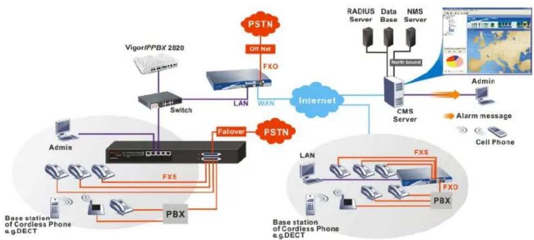
flowchart
graph TD
    subgraph PSTN
        A["Off Net"] --> B["PSTN"]
        B --> C["FXO"]
        C --> D["LAN"]
        D --> E["WAN"]
        E --> F["Internet"]
        F --> G["CMS Server"]
        G --> H["Admin"]
        H --> I["Alarm message"]
        I --> J["Cell Phone"]
    end

    subgraph LAN
        K["Switch"] --> L["Admin"]
        L --> M["Fialover"]
        M --> N["Base station of Cordless Phone e.g.DECT"]
        N --> O["PBX"]
        O --> P["Base station of Cordless Phone e.g.DECT"]
        P --> Q["FXS"]
        Q --> R["Base station of Cordless Phone e.g.DECT"]
        R --> S["PBX"]
        S --> T["Base station of Cordless Phone e.g.DECT"]
        T --> U["LAN"]
        U --> V["Data Base"]
        V --> W["NMS Server"]
        W --> X["North bound"]
    end

    subgraph CMS Server
        Y["RADIUS Server"] --> Z["Admin"]
    end

    style PSTN fill:#f9f,stroke:#333
    style LAN fill:#ccf,stroke:#333
    style W fill:#cfc,stroke:#333
    style CMS Server fill:#fcc,stroke:#333
    style Admin fill:#ffc,stroke:#333
    style Cell Phone fill:#fcc,stroke:#333
    style Alarm message fill:#ffc,stroke:#333
Internet Telephony, also known as Voice over Internet Protocol (VoIP), is a technology that allows you to make telephone calls using a broadband Internet connection instead of a regular (analog) phone line. Combining a PBX with the adapter allows you to call anyone who has an Internet phone or a traditional telephone number – including local, long distance, mobile, and international numbers. Internet Telephony offers features and services that are unavailable with a traditional phone at no additional cost. Because Internet Telephony requires strictly minimal packet delay and jitter (since voice quality is intolerant of packet loss), the adapter integrates VoIP feature with QoS and packet loss concealment mechanisms to effectively transport high priority voice traffic over IP with low latency. Another feature is T.38 fax relay. By enabling and configuring fax rate on a dial peer, the originating and the terminating adapter can enter fax relay transfer mode. By using the T.38 function, customers can also save on fax expenses.
1.1 LED Indicators and Connection
The VigorTalk ATA-24 has 2 WAN interfaces. Each interface can be connected to an individual Internet Service Provider. The VigorTalk ATA-24 also supports a backup function for WAN interfaces – a user can select one WAN interface to be a backup interface. If the master interface fails, the backup interface will take the place of the master interface immediately.
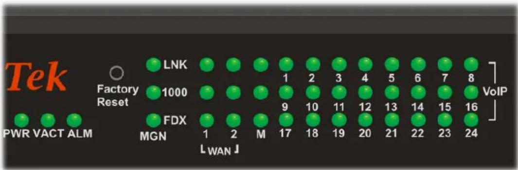
| LED | Status | Explanation | |
| On The adapter is powered on. PWR | |||
| Off The adapter is powered off. | |||
| VACT | On/Blinking | The system is active. | |
| Off The system is hanged. | |||
| ALM On The system alarm is active. | |||
| MGN | LNK | On The Ethernet link is established. | |
| Blinking The data transmission is done through the corresponding port. | |||
| Off No Ethernet link is established. | |||
| 1000 | On It means that a normal 1000 Mbps connection is through its corresponding port. | ||
| Off It means that a normal 100/10 Mbps connection is through its corresponding port. | |||
| FDX | On It means a full duplex connection on corresponding port. | ||
| Off It means a half duplex connection on corresponding port. | |||
| WAN/MIR | LNK | On The Ethernet link is established on corresponding port. | |
| Off No Ethernet link is established. | |||
| ROR | 1000 | On It means that a normal 1000 Mbps connection is through its corresponding port. | |
| Off It means that a normal 100 Mbps connection is through its corresponding port. | |||
| FDX | On It means a full duplex connection on corresponding port. | ||
| Off It means a half duplex connection on corresponding port. | |||
| VoIP (1-24) | On The phone is off hook (the handset of phone is hanging). | ||
| Blinking A phone call is incoming or on-line. | |||
Factory Reset:
Used to restore the default settings. Turn on the adapter (VACT LED is blinking). Press the hole and hold for more than 5 seconds. When you see the VACT LED begins to blink rapidly than usual, release the button. Then the adapter will restart with the factory default configuration.
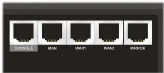
| Interface Description | |
| CONSOLE Provided for technician use. | |
| MGN Connector for local management. | |
| WAN (WAN1 ~ WAN2) Connector for remote networked devices. | |
| MIRROR Connector for security monitor. | |
1.2 Hardware Installation
Before starting to configure the adapter, you have to connect your devices correctly.
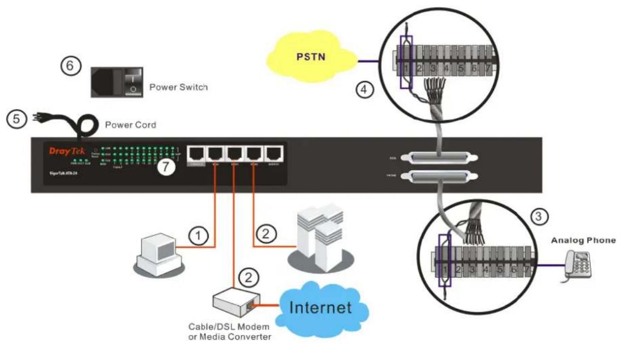
- Connect one end of an Ethernet cable (RJ-45) to the MGN ports of VigorTalk ATA-24. Connect the other end of the cable (RJ-45) to the Ethernet port on your computer.
- Connect a server/modem/adapter (depends on your requirement) to any available WAN port of the device with Ethernet cable (RJ-45).
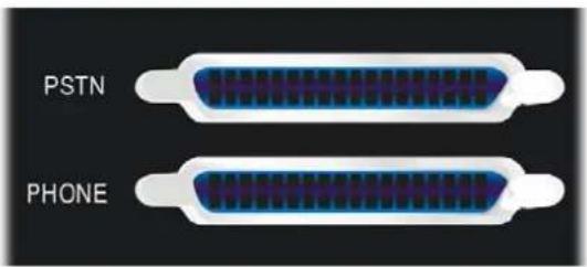
- Connect telephone sets to the Phone port of VigorTalk ATA-24 with telephone lines (RJ-11 to RJ-11).
- Connect the PSTN port to PABX.
- Connect the power cord to the power port of VigorTalk ATA-24 adapter on the rear panel, and the other side into a wall outlet.
- Power on the device by pressing the power switch on the rear panel.
- The system starts to initiate. The PWR LED should be ON. After completing the system test, the ACT LED will light up and start blinking. The MGN/WAN LED for that port on the front panel will light up.
Below shows an outline of the hardware installation for your reference (take VigorTalk ATA-24 as an example).
flowchart
graph TD
    A["Power Switch"] --> B["Power Cord"]
    B --> C["DrayTek"]
    C --> D["Cable/DSL Modem or Media Converter"]
    D --> E["Internet"]
    F["PSTN"] --> G["Analog Phone"]
    G --> H["Analog Phone"]
    style A fill:#f9f,stroke:#333
    style B fill:#ccf,stroke:#333
    style C fill:#cfc,stroke:#333
    style D fill:#fcc,stroke:#333
    style E fill:#cff,stroke:#333
    style F fill:#ffc,stroke:#333
    style G fill:#cfc,stroke:#333
    style H fill:#fcc,stroke:#333
1.2.1 Detailed Explanation for the Connector
Here provides you detailed explanation for some specific connectors that you have to be familiar.
The RS232 Connector
The RJ45 connection jet is used for CLI commands for system configuration and control functions in the VigorTalk ATA-24. The jet is used for initialization of the VigorTalk ATA-24 during preliminary installation. The “management cable”, as shown below, converts the RJ45 to the RS232 interface. The RJ45 jet connects to a console interface in the VigorTalk ATA-24, while the RS232 DB9 connects to a console port on the computer. The default setting of the console port is “baud rate 57600, no parity, and 8 bit with 1 stop bit.”

Standard 10/100 Base-T Ethernet Interface Connector
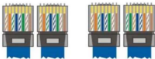
RJ45 jets provide 10/100 Base-T Ethernet interfaces. The interface supports MDI/MDIX auto-detection of either straight or crossover RJ45 cables. These cables are used on WAN, LAN, and DMZ interfaces.
natural_image
Four identical diagrams showing a device with colored wires and connectors, no text or symbols present.Chassis Connections
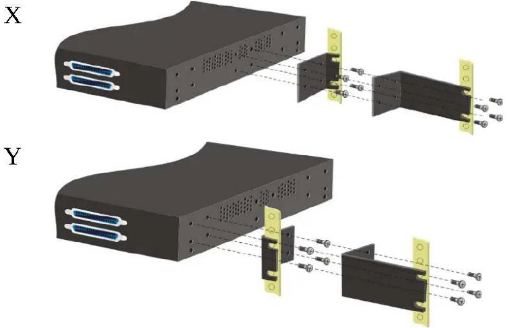
The VigorTalk ATA-24 can be mounted on a rack by using standard brackets in a 19-inch rack or optional larger brackets on 23-inch rack (not included). The bracket for 19- and 23-inch racks are shown below.

natural_image
Two black metal bracket components with mounting holes, shown from different angles (no text or symbols)Attach the brackets to the chassis of a 19- or a 23-inch rack (as shown in the figures below). Repeat the above procedure for the second bracket, which attaches the other side of the chassis.
natural_image
Technical illustration of two electronic device modules (X and Y) showing internal components connected to connectors, with no visible text or symbols.After the bracket installation, the VigorTalk ATA-24 chassis can be installed in a rack by using four screws for each side of the rack.
Desktop Type Installation
Rubber pads are included with the VigorTalk ATA-24. These rubber pads improve the air circulation and decrease unnecessary rubbing on the desktop.
2
Configuring Basic Settings
For use the adapter properly, it is necessary for you to change the password of web configuration for security and adjust primary basic settings.
This chapter explains how to setup a password for an administrator and how to adjust basic settings for accessing Internet successfully.
2.1 Changing Password
To change the password for this device, you have to access into the web browser with default password first.
- Make sure your computer connects to the adapter MGN port correctly.

Notice: You may set up the IP address of the computer to be the same subnet as the default IP address of Vigor adapter 192.168.1.1. For the detailed information, please refer to the later section - Trouble Shooting of this guide.
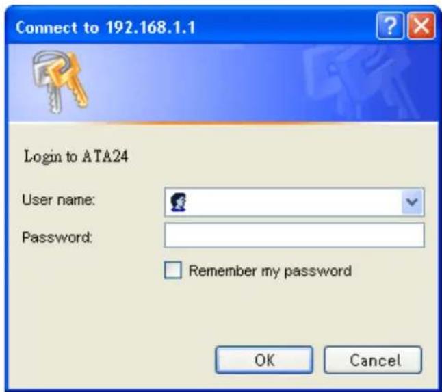
- Open a web browser on your PC and type http://192.168.1.1. A pop-up window will open to ask for username and password. Please type default values on the window for the first time accessing. The default value for user name is admin and the password is 1234. Next, click OK.
- Now, the Main Screen will pop up.
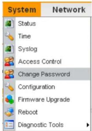
- Go to System page and choose Change Password.
- The following screen will appear.
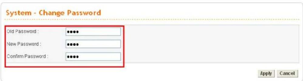
-
Enter the login password (1234) on the field of Old Password. Type a new one in the field of New Password and retype it on the field of Confirm Password. Then click Apply to continue.
-
Now, the password has been changed. Next time, use the new password to access the Web Configurator for this adapter.
-
Next, you will see the login screen after clicking Apply. Please use new password to re-enter the system configuration.
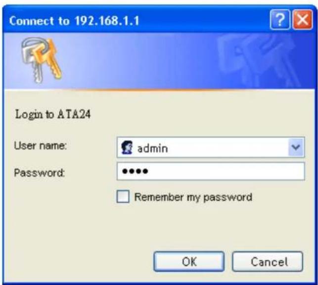
2.2 Quick Setup
Quick Setup is designed for configuring your broadband adapter accessing Internet with simply steps. There are two phases of quick setup, one is WAN configuration and the other is LAN configuration.
2.2.1 Adjusting WAN Connection Mode
In the Quick Setup group, you can configure the adapter to access the Internet with different modes such as Static and DHCP modes. For most users, Internet access is the primary application. The adapter supports the Ethernet WAN interface for Internet access. The following sections will explain in more detail the various broadband access configurations. All settings in this section will be applied in the first WAN1 interface.
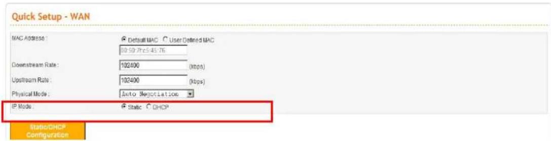
Now, you have to select an appropriate WAN connection type for connecting to the Internet through this adapter according to the settings that your ISP provided.
MAC Address Adapter Default-
Use the default Mac address stored originally in adapter.
User Definition-
Use a MAC address defined by the user.
Downstream Rate Assign the downstream rate for this WAN interface. The default value is 102400 kbps (100 Megabit). This setting is very important
for VigorTalk ATA-24 incoming buffer adjustment. If you use a DSL subscriber service with a 2Mbps downstream, please set the downstream rate setting with 2Mbps.
Upstream Rate Assign the transmission rate for this WAN interface. The default value is 102400 kbps (100 Megabit). This setting is very important for VigorTalk ATA-24 outgoing buffer adjustment. If you use a DSL subscriber service with a 256Kbps downstream, please set the downstream rate setting with 256Kbps.
Type Select a connection type for this WAN interface. Currently, there is only one setting offered for you to choose - Fast Ethernet.
Physical Mode Select connection speed mode for this WAN interface. There are auto negotiation, full duplex, and half duplex of either 10/100/1000M speed options for the WAN Interface.
IP Mode Select an IP mode for this WAN interface. There are two available modes for Internet access, Static or DHCP. On this page you may configure the WAN interface to use Static (fixed IP) or DHCP (dynamic IP address). Most of the cable users will use the DHCP mode to get a globally reachable IP address from the cable host system.
2.2.2 Static Mode
You can manually assign a static IP address to the WAN interface and complete the configuration by applying the settings and rebooting your adapter. Choosing Static as the IP mode, you will see the following page:
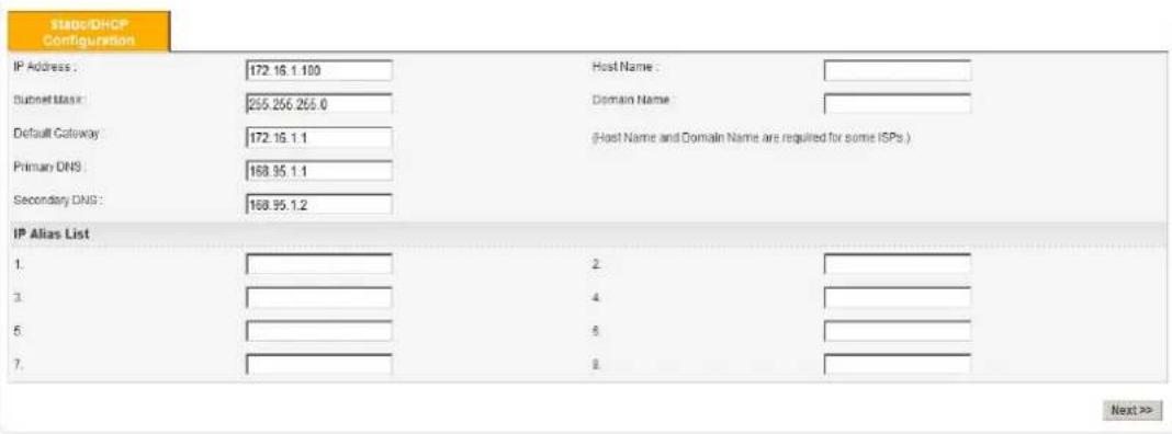
All the settings here are set by privately. Your ISP will not provide these settings.
| IP Address | Assign a private IP address to the WAN interface. |
| Subnet Mask | Assign a subnet mask value to the WAN interface. |
| Default Gateway | Assign a private IP address to the gateway. |
| Primary DNS | Assign a private IP address to the primary DNS. |
| Secondary DNS | Assign a private IP address to the secondary DNS. |
| IP Alias List | Assign other IP addresses to be bound to this interface. This setting is optional. |
After setting up the WAN interface, the user can click Next to setup the LAN interface continuously.
LAN - LAN IP/DHCP Page
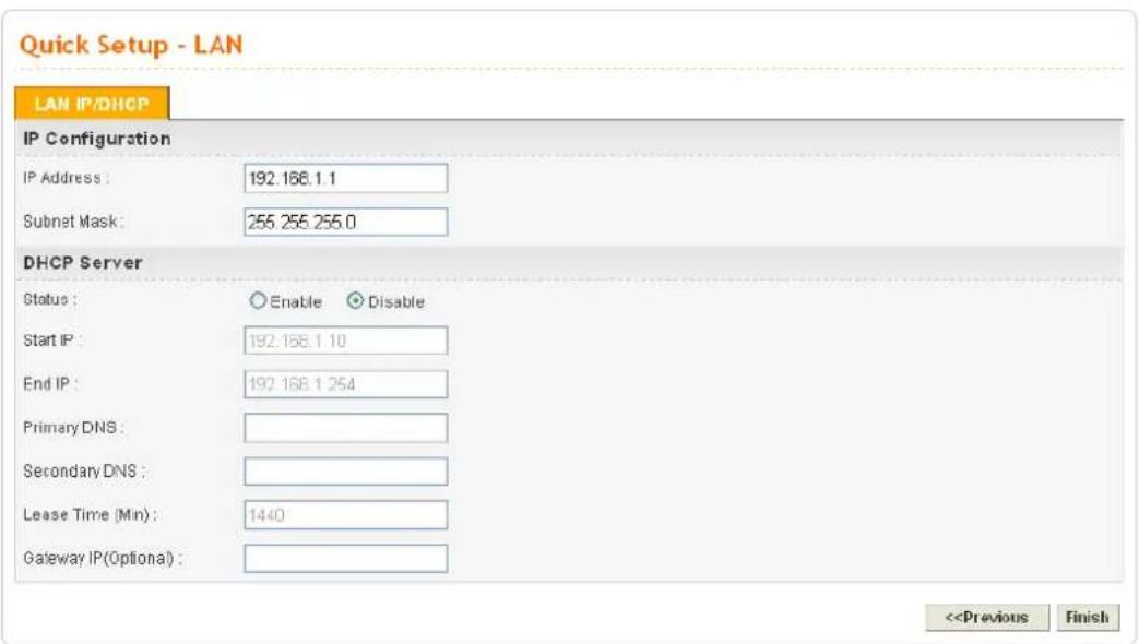
LAN - LAN IP/DHCP Page
3.1.1 Status
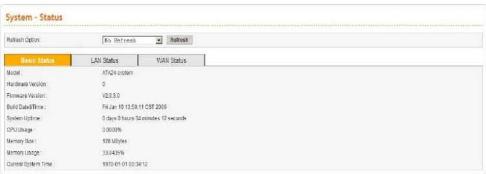
The online Status function provides some useful system information on the current status of the VigorTalk ATA-24. A user can observe the system status on this Web page and determine which setting needed to be changed in corresponding web pages. In the System group, click the Status option. The online Status Web page contains three parts: Basic Status, LAN Status, and WAN Status.Refresh Option
You can choose to automatically refresh the Web page information. There are four options given as shown below. No Refresh: Static information page. Every 10 Seconds: Refreshes the page every 10 seconds. Every 20 Seconds: Refreshes the page every 20 seconds. Every 30 Seconds: Refreshes the page every 30 seconds.Basic Status
General status of this adapter will be displayed on Basic Status page.  Model Displays the model name of the adapter. Hardware Version Displays the hardware version of the adapter. Firmware Version Displays the firmware version of the adapter. Build Date&Time Displays the date and time of the current firmware build. System Uptime Displays the amount of time that the adapter has been online. CPU Usage Displays the average percentage of the CPU being used. Memory Usage Displays the percentage of memory being used. Current System Time Displays the current local system time.LAN Status
The status of LAN connection is shown in this page. Simply click LAN Status tag to get the detailed.  IP Address Displays the IP address of the LAN interface. MAC Address Displays the MAC address of the LAN Interface. High Available Status The High Available Status is shown when the function is enabled. When there are two VigorTalk ATA-24 devices in the same LAN, one can be set as Master device and the other can be set as Slave device. Master - It means that VigorTalk ATA-24 plays the Master role in high availability feature. Slave - It means that VigorTalk ATA-24 plays the Slave role in high availability feature. If there is only one VigorTalk ATA-24 used in LAN, this line will be blank. RX Packets Displays the total number of received packets at the LAN interface. TX Packets Displays the total transmitted packets at the LAN interface.WAN Status
The status of WAN interface (Static or DHCP) is shown in this page. Simply click WAN Status tag to get the detailed. There are four sets of WAN status can be shown in this page at one time. The sample below just lists one set of WAN status for only WAN1 interface is used.  IP Address Displays the IP address of the WAN interface. MAC Address Displays the MAC address of the WAN Interface. Primary DNS Displays the IP address of the primary DNS. Secondary DNS Displays the IP address of the secondary DNS. Gateway Displays the IP address of the default gateway. RX Packets Displays the total received packets for each WAN interface. TX Packets Displays the total transmitted packets for each WAN interface. Connection Status Displays the connection status of the WAN interface. Up Time Displays the total system uptime of the interface. Disconnect Disconnects current connection.3.1.2 Time
As an NTP (Network Time Protocol) client, the adapter gets standard time from the time server. Some time-based functions, such as Call Schedule and URL Content filtering, cannot work properly until the system time functions run successfully. Typically, NTP achieves high accuracy and reliability with multiple redundant servers and diverse network paths. The VigorTalk ATA-24 supports synchronization with a specific NTP server or the remote PC host of the administrator. In the System group, click the Time option. The Time page is shown below:  Use Browser Time Click this option to use the browser time from the remote administrator PC host as adapter's system time. Use NTP Time Click this option to use the time from an NTP server as adapter's system time. NTP Server Assign a public IP address or domain name of the NTP server. Time Zone Select the time zone where the VigorTalk ATA-24 is located. Daylight Savings Time Select Use to activate this function. This function is useful for some areas. Update Interval Select a time interval for updating from the NTP server. Apply Click Apply to save these settings.3.1.3 Syslog
The VigorTalk ATA-24 supports a Syslog function to keep a record of abnormal conditions. The adapter will send Syslog packets to a Syslog server on the remote site. The administrator can observe any abnormal events from VigorTalk ATA-24. In the System group, click the Syslog option. The Syslog web page is shown below: Status
Click Enable to activate this function. The adapter will send system log message for your reference. If you click Disable, the adapter will not send out any message about system log.Syslog Server IP
The IP address of the Syslog server. If a user assigns an IP address of "0.0.0.0", the Syslog function will be disabled. Then, VigorTalk ATA-24 will not send Syslog packets to the Syslog server.Syslog Server Port
Assign a port for the Syslog protocol.Apply
Click Apply to save these settings.3.1.4 Access Control
This page allows you to determine which services (HTTP/Telnet/SSH) is used for the user to access VigorTalk ATA-24. In addition, you can also limit some hosts to access VigorTalk ATA-24 with specified IP address. In the System group, click the Access Control option. You will get the following page:  Management Method There are three management methods provided here for you to choose for your adapter. Check HTTP/Telnet/SSH for the adapter. Allow Management from the WAN Disable - Disable the management from the WAN interface. Enable All - Enable all management (through HTTP/Telnet/SSH) from the WAN interface. Enable User Defined WAN IP - System can be managed by these three IP addresses via WAN. Allowed IP1(to 3) - Type in ranges for IP addresses (up to three) for managing the system. Management Port Default Ports - Use the default ports for HTTP and Telnet if you choose HTTP and Telnet as management methods. User Defined Ports - Or you can assign new port numbers for HTTP, Telnet and SSH respectively. PING Restriction Disable PING from the LAN -Choose this function to reject all ICMP packets from LAN side. Disable PING from the WAN - Choose this function to reject all ICMP packets from WAN side.3.1.5 Configuration
Most of the settings can be saved locally as a configuration file, and can be applied to another adapter. The VigorTalk ATA-24 supports the restoring and uploading functions of the configuration files. In the System group, click the Configuration Setup option. And you can see the following page. Select a Configuration File
Please click the Browse... button to find out the location of the configuration file to be uploaded to the adapter and click Apply.Backup Configuration File Push Backup Button
Download the configuration file to a local host. The default file name is "ata24.cfg".3.1.6 Firmware Upgrade
VigorTalk ATA-24 allows users to upgrade firmware through a Web interface. In the System group, click the Firmware Upgrade option. You can see the following page then. Before you execute the firmware upgrade, please download the newest firmware from Draytek's website (www.draytek.com) or FTP site (ftp.draytek.com) on the computer first.  Caution Displays a caution for your reference. Current Version Displays current firmware version that you are using. Location Local means upgrade firmware from browser. Remote means upgrade firmware from a remote TFTP server.| Firmware | Specify the location of the firmware file if you want to upgrade the firmware locally. |
| TFTP Server IP | If you want to upgrade the firmware of this adapter from remote side, please type the IP address of the TFTP server. |
| Remote File Name | The default filename will be shown here. If you have use another name to save the firmware file, please type the new name in this field. |
| Apply | After finished your selection, please click Apply to execute the firmware upgrade. |
Firmware Upgrade from a Console Port
Firmware upgrade can be done from a console port, too. The following example was run on a Windows environment. 1. Download the newest firmware from the DrayTek Website (www.draytek.com.tw) or FTP site (ftp.draytek.com) on your computer first. 2. Connect the RJ45 connector of console cable to the console port on VigorTalk ATA-24 and the DB9 connector of the console cable to the RS232 port on the PC.  The default setting of the console port is “baud rate 115200, no parity, and 8 bit with 1 stop bit.” 3. Power on VigorTalk ATA-24, then press ENTER before the system reboots completely.  4. Type LAN IP, TFTP Server IP, Image Name one by one, and press ENTER. 5. The firmware upgrade begins. 6. After firmware upgrade is finished, the device will restart. 3.1.7 Commit
Commit can save the current settings. Please click Apply to save the VigorTalk ATA-24 system settings.System - Commit
This action will save your configure! Apply3.1.8 Reboot
The VigorTalk ATA-24 system can be restarted from a Web browser. Reboot screen can appear after you finish the changing of WAN and LAN settings. You have to reboot the adapter to invoke the configured settings that you made before. Besides, you can select Reset to factory default to reboot the device and retrieve the default settings. In the System group, choose the Reboot option. In the web page of Reboot, a user must either keep the current configuration settings or use the default configuration after the VigorTalk ATA-24 system has been rebooted.System - Reboot
System rebooting will take 20 seconds □ Reset to factory default Apply Click Apply to reboot the whole system. The rebooting procedure usually takes 70 or more seconds. 3.1.9 Diagnostic Tools
In some cases, a user may need to know some information about the adapter, such as static or dynamic databases, or other routing information. The VigorTalk ATA-24 supports four functions, Routing Table, ARP Cache Table, and DHCP Assignment Table for the user to review such information. In the System group, click the Diagnostic Tools option  \- Select View Routing Table to get the following page:  Destination Displays the destination IP address for various routings. Gateway Displays the default gateway. Subnet Mask Displays the subnet mask for various routings. Flags Displays the status of the routing entries. Interface Denoted by vlan4040 if it is a LAN interface and vlan4041 if it is a WAN interface. Refresh Click Refresh to re-display this web page for getting newest routing information. \- Select View ARP Cache Table to get the following page:  IP Address Displays the IP address for different ARP cache. MAC Address Displays the MAC address for different ARP cache. Interface Denoted by vlan4040 if it is a LAN interface. vlan4041 means it is a WAN1 interface; vlan4042 means it is a WAN2 interface; vlan4043 means it is a WAN3 interface. Refresh Click Refresh to re-display this web page for getting newest ARP information. \- Select View DHCP Assignment Table to get the following page:  Assigned IP Displays the IP address of the static DHCP server. MAC Address Displays the MAC address of the static DHCP server. Time Left Displays the remaining time for this IP address assigned by DHCP server. When the time expired, such IP address would not be kept for this client and might be assigned to other client. Refresh Click Refresh to re-display this web page for getting newest routing information.3.2 Network Setup
For Internet access, it is necessary for you to set WAN and MGN interfaces for the adapter. 3.2.1 WAN and Internet Access Setup
The VigorTalk ATA-24 supports two WAN interfaces (with two IP Modes – Static or DHCP), which share the same setting page. In the Network group, please click the WAN option. The following page will be shown. Backup
Enables or disables backup function for WAN interfaces. If you enable this function, the backup-master/backup-slave will execute the job of master/slave device when the master/slave device fails to work. Edit Open the configuration page of this WAN interface. IP Mode Displays current mode of this WAN interface. There are two options: Static or DHCP Active Activates/closes this WAN interface. Default Route Sets this WAN interface as default route interface. Backup-Master Sets this WAN interface as a master interface. WAN1 must be assigned as Master interface if Backup function is enabled. Backup-Slave Sets this WAN interface as a slave interface. VoIP Sets this WAN interface as VoIP default interface. Most users will use their adapters primarily for Internet access. The VigorTalk ATA-24 supports broadband Internet access and provides multiple WAN interfaces. The following sections will give a detailed illustration to broadband access methods. Click the "Edit" icon to bring up the WAN configuration page for the corresponding interface.  Default MAC Uses the default Mac address. User Defined MAC Uses a MAC address defined by users. If you select this item, you have to type the MAC address in the box below. Downstream Rate Sets downstream rate for this WAN interface. The default value is 102400 kbps (100 Megabit). Upstream Rate Sets transmission rate for this WAN interface. The default value is 102400 kbps (100 Megabit). Physical Mode Sets connection speed mode. There are five options including Auto negotiation, full duplex, half duplex, 10M, 100M and 1000M. IP Mode Sets an IP Mode with Static (fixed IP) or DHCP (dynamic IP address) and creates the IP group information. Most cable modem users will use DHCP to get a globally reachable IP address from the cable head-end system. Different mode will lead different configuration and will be explained in later section. Before you connect a broadband access device e.g. a DSL/Cable modem to VigorTalk ATA-24, you need to know what kind of Internet access your ISP provides. The following sections introduce four widely used broadband access services: Static for DSL, DHCP for Cable modem. In most cases, you will get a DSL or cable modem from the broadband access service provider. VigorTalk ATA-24 is connected behind the broadband device i.e. DSL/cable modem and works as a NAT or IP adapter for broadband connections. Next, we will introduce each WAN mode in detailed.Static IP Configuration
It means that the IP group information for WAN interface is manually assigned by the user.  IP Address Sets the private IP address of WAN interface. Subnet Mask Sets the subnet mask value of WAN interface. Default Gateway Sets the private IP address of gateway. Primary DNS Sets the private IP address of primary DNS. Secondary DNS Sets the private IP address of secondary DNS. MTU It means the maximum transmission unit. Default value is 1500. Change it if you want. Host Name Some ISP may ask you to type your host name. Please type in if necessary.Domain Name
Some ISP may ask you to type your domain name. Please type in if necessary. Detect Type Select a detecting type for this WAN interface. There are three ways Send ARP to Gateway, Send PING and Send HTTP Request supported in ATA24.  Detect Interval (sec) Assign an interval period of time for each detecting. The minimum value is 3 and no limit for maximum value. No-Reply Count Assign detecting times to ensure the connection of the WAN. After passing the times you set in this field and no reply received by the adapter, the connection of WAN interface will be regarded as breaking down. Detect Destination Host (IP or Domain Name) Assign an IP address or Domain name as a destination to be detected whether the host is active (sending reply to the adapter) or not. If not, the connection of WAN interface will be regarded as breaking down. This function is available when Detect Type is set with Send PING or Send Http Request. IP Alias List Sets other IP addresses binding in this interface. You can set up to 32 sets of IP alias settings. If you have typed addresses here, you can see and choose it in later web page settings. Apply Click Apply to go back to the WAN Interface Configuration page. To apply all settings, click Apply on the WAN Interface Configuration page and reboot your adapter. Reset Click this button to clear all the configurations for this page.DHCP Configuration
If the WAN interface is set as a DHCP client, the VigorTalk ATA-24 will ask for IP network settings from the DHCP server or DSL modem automatically. It is not necessary for users to manually configure the adapter.  MTU It means the maximum transmission unit. Default value is 1500. Change it if you want. Host Name Some ISP may ask you to type your host name. Please type in if necessary. Domain Name Some ISP may ask you to type your domain name. Please type in if necessary. Detect Type Select a detecting type for this WAN interface. There are three ways Send ARP to Gateway, Send PING and Send HTTP Request supported in the adapter.  Detect Interval (sec) Assign an interval period of time for each detecting. The minimum value is 3 and no limit for maximum value. No-Reply Count Assign detecting times to ensure the connection of the WAN. After passing the times you set in this field and no reply received by the adapter, the connection of WAN interface will be regarded as breaking down. Detect Destination Host (IP or Domain Name) Assign an IP address or Domain name as a destination to be detected whether the host is active (sending reply to the adapter) or not. If not, the connection of WAN interface will be regarded as breaking down. This function is available when Detect Type is set with Send PING or Send Http Request.Apply
Click Apply to go back to the WAN Interface Configuration page. To apply all settings, click Apply on the WAN Interface Configuration page and reboot your adapter. Reset Click this button to clear all the configurations for this page.3.2.2 MGN
In the Network group, select MGN option. The following page for LAN IP/DHCP will be shown.  IP Address Type the IP address for LAN/DHCP. Subnet Mask Type the subnet mask for the LAN IP/DHCP.Status
Click Enable the DHCP server; click Disable to close DHCP server. Start IP Sets the starting IP address of the IP address pool for DHCP server. End IP Sets the ending IP address of the IP address pool for DHCP server. Primary DNS Sets the private IP address of the primary DNS. Secondary DNS Sets the private IP address of the secondary DNS. Lease Time (Min) Sets a lease time for the DHCP server. The time unit is minute. Gateway IP (Optional) Sets a gateway IP address for the DHCP server. Click Apply to reboot the system and apply the settings.3.2.3 High Availability
The High Availability (HA) feature refers to the awareness of component failure and the availability of backup resources. The complexity of HA is determined by the availability needs and the tolerance of system interruptions. Systems, that provide nearly full-time availability, typically have redundant hardware and software that makes the system available despite failures. The high availability is designed to avoid single points-of-failure. When failures occur, the failover process moves processing performed by the failed component (the “Master”) to the backup component (the “Slave”). This process remains system-wide resources, recovers partial of failed transactions, and restores the system to normal within a matter of microseconds. Take the following picture as an example. The left device is regarded as Master device, the right device is regarded as Slave device. When Master device is broken down, the Slave device could replace the Master role to take over all jobs as soon as possible. However, once the original Master is working again, the Slave would be changed to original role to stand by. flowchart
graph TD
    A["Internet/WAN"] --> B["Master Router Configurations"]
    A --> C["Slave Router Configurations"]
    B --> D["LAN IP:192.168.1.1\nLAN MAC:00-50-7F-0A-0B-01"]
    B --> E["High Availability: Enable\nGroup Number*:1\nRole: Master\nVirtual IP*:192.168.1.3\nVirtual MAC**:00-00-5E-00-01-01"]
    C --> F["LAN IP:192.168.1.2\nLAN MAC:00-50-7F-0A-0B-02"]
    C --> G["High Availability: Enable\nGroup Number*:1\nRole: Slave\nVirtual IP*:192.168.1.3\nVirtual MAC**:00-00-5E-00-01-01"]
3.3 Advanced Setup
In the Advanced menu, there are several items offered here for you to adjust for the adapter. 3.3.1 Static Route Setup
When you have several subnets in your LAN, sometimes a more effective and quicker way for connection is the Static routes function rather than other methods. You may simply set rules to forward data from one specified subnet to another specified subnet without the presence of RIP. This function allows users to assign static routing information. In the Advanced group, choose Static Route. You will get the following page.  Network Interface Displays the network interface (LAN, WAN1, 2, 3 or 4). Gateway IP Displays the gateway address of the static route. Destination IP Displays the destination IP of the static route. Mask Displays the subnet mask of this route. Edit Allows users to edit the selected static route settings. Delete/Delete All Removes one or all the selected static route settings. The system allows users to set up to 10 static routes for the adapter.Edit the Static Route
To edit static route for certain item, select the radio button of the item and click Edit on the bottom of the page. The following web page will be displayed:  Network Interface Select a network interface as a destination to be sent. It includes LAN, and WAN1\~WAN3. Gateway IP Assign an IP address of the gateway for the interface selected above. Destination IP Assign the IP address of the destination that data will be transferred to. Packets ready to destination will be sent out through the network interface chosen in this page. Subnet Mask Assign a value of subnet mask for destination IP address. Click Apply to reboot the system and apply the settings.Delete the Static Route
Select the radio button of the item that you want to delete and click Delete on the bottom of the page. The following web page will be displayed:  Click OK to delete the entry in static route table. Users can click Delete All to remove all entries in static route table.3.3.2 Port Block
The Port Block function provides a user to set lots of proprietary port numbers. Packets will be dropped if destination ports (both TCP and UCP) of packets with these assigned port numbers are on WAN and LAN. The advantage of this feature is to filter some unnecessary packets or attacking packets on Internet environment or LAN network. VigorTalk ATA-24 supports ten port numbers to be blocked. In the Advanced group, click Port Block option. You will get the following page.  Index The number of each entry.Status
User can Disable or Enable the port block for the specified port. Port Number Assign a port number to be blocked in system. The default port setting is 135. Click Apply to finish this setting.3.3.3 DDNS
The Dynamic DNS function allows the adapter to update its online WAN IP address, which assigned by ISP or other DHCP server to the specified Dynamic DNS server. Once the adapter is online, you will be able to use the registered domain name to access the adapter or internal virtual servers from the Internet. DDNS is more popular on dynamic IP users, who typically receive dynamic, frequently-changing IP addresses from their service provider. Before you set up the Dynamic DNS function, you have to subscribe free domain names from the Dynamic DNS service providers. The adapter provides up to ten accounts for the function and supports the following providers: www.dynsns.org, www.no-ip.com, www.dtdns.com, www.changeip.com, www.ddns.cn. You should visit their websites for registering your own domain name on the adapter. In the Advanced group, click DDNS option. You will get the following page.| # | Domain Name | Server Provider | Server Type | Active | Status |
| 1 | dyndns.org | dynamic | disable | Not Connected | |
| 2 | dyndns.org | dynamic | disable | Not Connected | |
| 3 | dyndns.org | dynamic | disable | Not Connected | |
| 4 | dyndns.org | dynamic | disable | Not Connected | |
| 5 | dyndns.org | dynamic | disable | Not Connected | |
| 6 | dyndns.org | dynamic | disable | Not Connected | |
| 7 | dyndns.org | dynamic | disable | Not Connected | |
| 8 | dyndns.org | dynamic | disable | Not Connected | |
| 9 | dyndns.org | dynamic | disable | Not Connected | |
| 10 | dyndns.org | dynamic | disable | Not Connected |
Server Type
Select Static, Dynamic or Custom type for this entry of DDNS settings. Domain Name Assign a private domain name to be accessed. Login Name Assign a name to login into DDNS server. Login Password Assign a password to login into DDNS server. Wild Card If you want anything-here.yourhost.dyndns.org to work (EX. To make things like www.yourhost.dyndns.org work), click "Enable" to active this function.Backup MX
MX stands for Mail Exchanger. Mail Exchangers are used for directing mail to specific servers other than the one a hostname points at. Mail Extender Assign an email address. Click Apply to finish these settings and return to previous page.Note:
1. The Wildcard and Backup MX features are not supported for all Dynamic DNS providers. You could get more detailed information from their websites. 2. Backup MX provides a secondary mail server to hold your e-mail if your main email server go offline for any reason. Once you go back online, your email will be delivered to you.3.3.4 Port Mirroring
VigorTalk-ATA Series supports port mirroring function in WAN interfaces. Generally speaking, this function copies traffic from one or more specific ports to a target port. This mechanism helps manager track the network errors or abnormal packets transmission without interrupting the flow of data access the network. By the way, user can apply this function to monitor all traffics which user needs to check. There are some advantages supported in this feature. Firstly, it is more economical without other detecting equipments to be set up. Secondly, it may be able to view traffic on one or more ports within a VLAN at the same time. Thirdly, it can transfer all data traffics to be mirrored to one analyzer connect to the mirroring port. Last, it is more convenient and easy to configure in user's interface. In the Advanced group, click the Port Mirroring option. You will see the following page. Enable/Disable
Click Disable to disable this function. Click Enable to activate this function. Mirroring Port Select a port to view traffic sent from mirrored ports. Mirrored Port(s) Click which ports are necessary to be mirrored. After finishing the settings, please click Apply.3.4 Firewall Setup
The firewall controls the allowance and denial of packets through the adapter. The Firewall Setup in the VigorTalk ATA-24 Series mainly consists of Denial of Service (DoS) only. The firewall filters help to protect your computer against attack from outsiders. The following sections will explain how to configure the Firewall. The DoS facility can detect and mitigate the DoS attacks. T 3.4.1 DoS
The DoS function helps to detect and mitigates DoS attacks. These include flooding-type attacks and vulnerability attacks. Flooding-type attacks attempt to use up all your system's resources while vulnerability attacks try to paralyze the system by offending the vulnerabilities of the protocol or operation system. In the Firewall group, click the DOS option. You will see the following page. The DoS Defense Engine inspects each incoming packet against the attack signature database. Any packet that may paralyze the host in the security zone is blocked. The DoS Defense Engine also monitors traffic behavior. Any anomalous situation violating the DoS configuration is reported and the attack is mitigated. DoS Defense
Enables or disables the DoS Defense function. The default value is Disable.Enable SYN Flood Defense
Activates the SYN flood defense function. If the amount of TCP SYN packets from the Internet exceeds the user-defined threshold value, the adapter will be forced to randomly discard the subsequent TCP SYN packets within the user-defined timeout period. The default setting for threshold and timeout are 300 packets per second and 10 seconds, respectively.Enable UDP Flood Defense
Activates the UDP flood defense function. If the amount of UDP packets from the Internet exceeds the user-defined threshold value, the adapter will be forced to randomly discard the subsequent UDP packets within the user-defined timeout period. The default setting for threshold and timeout are 300 packets per second and 10 seconds, respectively.Enable ICMP Flood Defense
Activates the ICMP flood defense function. If the amount of ICMP echo requests from the Internet exceeds the user-defined threshold value, the adapter will discard the subsequent echo requests within the user-defined timeout period. The default setting for threshold and timeout are 300 packets per second and 10 seconds, respectively.Enable Port Scan Detection
Activates the Port Scan detection function. Port scan sends packets with different port numbers to find available services, which respond. The adapter will identify it and report a warning message if the port scanning rate in packets per second exceeds the user-defined threshold value. The default threshold is 300 pps (packets per second). Enable Block IP Options Activates the Block IP options function. The adapter will ignore any IP packets with IP option field appearing in the datagram header. Enable Block Land Activates the Block Land function. A Land attack occurs when an attacker sends spoofed SYN packets with identical source address, destination addresses and port number as those of the victim. Enable Block Smurf Activates the Block Smurf function. The adapter will reject any ICMP echo request destined for the broadcast address. Enable Block Trace Route Activates the Block trace route function. The adapter will not forward any trace route packets. Enable Block SYN Activates the Block SYN fragment function. Any packets Fragment having the SYN flag and fragmented bit sets will be dropped. Enable Block Fraggle Attacks the Block fraggle Attack function. Any broadcast UDP packets received from the Internet are blocked. Enable TCP Flag Scan Activates the Block TCP flag scan function. Any TCP packet with an anomalous flag setting is dropped. These scanning activities include no flag scan, FIN without ACK scan, SYN FIN scan, Xmas scan and full Xmas scan. Enable Tear Drop Activates the Block Tear Drop function. This attack involves the perpetrator sending overlapping packets to the target hosts so that target host will hang once they re-construct the packets. The adapters will block any packets resembling this attacking activity. Enable Ping of Death Activates the Block Ping of Death function. Many machines may crash when receiving an ICMP datagram that exceeds the maximum length. The adapter will block any fragmented ICMP packets with a length greater than 1024 octets. Enable Block ICMP Activates the Block ICMP fragment function. Any ICMP Fragment packets with fragmented bit sets are dropped. Enable Block Unknown Protocol Activates the Block Unknown Protocol function. The adapter will block any packets with unknown protocol types. Click Apply to apply the settings when you finish the configuration.3.5 VoIP Setup
Voice over Internet Protocol (VoIP) is a technology that allows you to make telephone calls using a broadband Internet connection instead of a regular (or analog) phone line. The VigorTalk ATA-24 series provides cost effective voice solution for SME customers which can be explained with the following diagram. flowchart
graph TD
    A["Base station of Cordless Phone e.g.DECT"] --> B["PBX"]
    B --> C["Internet"]
    C --> D["PSTN"]
    D --> E["MSC/BS"]
    E --> F["Cell Phone"]
    E --> G["Phone"]
    E --> H["UK"]
    E --> I["Germany"]
    E --> J["France"]
    C --> K["EMS Server"]
    K --> L["North bound"]
    L --> M["<Alarm message>"]
    M --> N["Administrator"]
    N --> O["Cell Phone"]
    style A fill:#f9f,stroke:#333
    style B fill:#ccf,stroke:#333
    style C fill:#cfc,stroke:#333
    style D fill:#fcc,stroke:#333
    style E fill:#cff,stroke:#333
    style F fill:#ffc,stroke:#333
    style G fill:#ffc,stroke:#333
    style H fill:#ffc,stroke:#333
    style I fill:#ffc,stroke:#333
    style J fill:#ffc,stroke:#333
    style K fill:#fff,stroke:#333
3.5.1 Protocol
Select Protocol
There are three protocols can be used for VoIP phones – SIP, MGCP and H248. You should click either one of buttons to set corresponding settings for VoIP phones. Be aware that both sides (local end and remote end) should use same protocol for VoIP phones. ● For SIP Configuration
SIP Local Port Type the port number for SIP protocol. The default value is 5060. Active Click this box to activate this SIP proxy server setting. Outbound Proxy Check this box to enable this function for sending SIP protocol packets to an SIP proxy server. Proxy Name Type the name of the SIP proxy server. Proxy Address Type the IP address of the SIP proxy server. Proxy Port Type the port number of the SIP proxy server. Registrar Address Type the IP address or domain name of the SIP registrar server. Registrar Port Type the port number of the SIP registrar server. Expires Type the timeout value for SIP protocols. The default value is 300. Domain Type the IP address or domain name of the SIP Domain/Realm. User-Agent Name Type the name for the client's device. You can set up to 3 sets of SIP configurations in this page. - For MGCP Configuration  MGCP Call Agent Address The IP address of the Call Agent server in MGCP. MGCP Call Agent Port The UDP port number for the Call Agent server. MGCP Local Port The UDP port number in MGCP local terminal. EndPoint Name Style Choose a proper name style for the VoIP settings. There are three options for you to choose. aaln/#@[ip\_addr] - ex: aaln/1@[1.1.1.1] mac\_addr/#@[ip\_addr]- ex: 000504030201/1@[1.1.1.1] aaln/#@mac\_addr-ex:aaln/1@000504030201 aaln/#@ - ex: aaln/1@v3300.draytek.com Logic ID Starting Number The starting number for “#” used in EndPoint Name Style. The range for the number is from 1 to 24. That is, if you type 3 in this field, the number 3 to 26 will be available for applying Wild-carded RSIP For VoIP phone call with MGCP configuration, each port will send RSIP to call agent for notifying that port is initiated or restarted. Each endpoint sends its own RSIP – Each port must send one RSIP message (e.g., aaln/1@[172.16.3.5]) to call agent respectively. Send only one wild RSIP – Only one RSIP message (e.g., aaln/\*@[172.16.3.5]) will be sent to call agent to indicate all ports are initiated/restarted.Range Wildcard RSIP
Click Enable to send out RSIP message (e.g., aaln/\*@[172.16.3.5]). Click Disable to close such function.HearBeat
Click Enable to check if MGCP server can work normally or not, otherwise click Disable.HearBeat Period
Type the interval for the system to check the MGCP server. HearBeat Retry Type the times for the system to check the MGCP server.- For H248 Configuration
 H248 Call Agent Address The IP address of the Call Agent server in H248. H248 Call Agent The port number for the Call Agent server in H248. H248 MessageID Mode Choose one of the modes for MessageID (defined by H248). Settings configured in Message ID field are used to be identified by the server supported with H248.H248 MessageID IP Mode
If you choose WAN IP Address, the system will use WAN IP address configured in Network for such protocol; if you choose Manual IP Address, you have to type IP address manually in the field of H248 MessageID Address below.H248 MessageID Address
Type WAN IP address used for the server supported with H248 when you choose Manual IP address as H248 MessageID Address. H248 MessageID Port The port number for MessageID.H248 Local Port
The UDP port number in H248 local terminal.SIP Accounts
You have to set up your own SIP settings. When you apply for an account, your SIP service provider will give you relational information for you to type in this page.| # | User Name | Proxy Server | VoIP IP Address | Ring Port | Ring Type | Call Forwarding |
| 1 | 1001 | WAN | 1 | All Ports | ||
| 2 | 1002 | WAN | 2 | All Ports | ||
| 3 | 1003 | WAN | 3 | All Ports | ||
| 4 | 1004 | WAN | 4 | All Ports | ||
| 5 | 1005 | WAN | 5 | All Ports | ||
| 6 | 1006 | WAN | 6 | All Ports | ||
| 7 | 1007 | WAN | 7 | All Ports | ||
| 8 | 1008 | WAN | 8 | All Ports | ||
| 1234 | ||||||
Disable/Enable
Click Disable to close this setting. Click Enable to activate this setting. Username Enter your account name of SIP Address, e.g. every text before @. Password The password provided to you when you registered with a SIP service. Display Name The caller-ID that you want to be displayed on your friend's screen. Authentication ID Type the name or number used for SIP Authorization with SIP Registrar. Proxy Server Before you choose, please set SIP proxy server first in previous page (SIP Server Configuration).  Call without Registration Some SIP server allows user to use VoIP function without registering. For such server, please click Enable to invoke Call without register.VoIP Address
The interface is used to apply VoIP traffics. There are two options: WAN and LAN/VPN. If LAN/VPN is selected, VoIP can be applied through a VPN tunnel to create a high security Call Forwarding
There are four options for you to choose. Disable- It is to close call forwarding function. Callforwarding busy- It means the incoming calls will be forwarded into SIP URL only when the local system is busy. Callforwarding no answer after- It means if the incoming calls do not receive any response, they will be forwarded to the SIP URL by the time out. SIP URL- Type in the SIP URL (e.g., aaa@draytel.org or abc@iptel.org) as the site for call forwarded.IncomingCall Rings
Rings as all ports in the group- All the ring ports selected for such account will ring when VigorTalk receives any incoming call. Rings the first available port- The first ring port selected for such account will ring when VigorTalk receives any incoming call. Rings by round robin- All the ring ports selected for such account will ring one by one when VigorTalk receives any incoming call. Ring Port Setting VigorTalk-ATA allows to connect up to 24 ring port. For such account, please specify required ring port(s) by checking the box(es) for applying the configuration.3.5.2 Port Settings
Port Settings page allows users to set phone number and phone groups for different call receivers.| # | Edit | Active | SIP Account | Call Waiting | Hotline | Mic/Spk Gain | FAX | Codoc | DTMF | Port Locked |
| 1 | V | 1-1001 | 0 / 0 | T.39 Relay | G729A | RFC2833 | ||||
| 2 | V | 2-1002 | 0 / 0 | T.38 Relay | G729A | RFC2833 | ||||
| 3 | V | 3-1003 | 0 / 0 | T.39 Relay | G729A | RFC2833 | ||||
| 4 | V | 4-1004 | 0 / 0 | T.39 Relay | G729A | RFC2833 | ||||
| 5 | V | 5-1005 | 0 / 0 | T.38 Relay | G729A | RFC2833 | ||||
| 6 | V | 6-1006 | 0 / 0 | T.39 Relay | G729A | RFC2833 | ||||
| 7 | V | 7-1007 | 0 / 0 | T.39 Relay | G729A | RFC2833 | ||||
| 8 | V | 8-1008 | 0 / 0 | T.38 Relay | G729A | RFC2833 |
VoIP - Port Settings - Port1 - Edit
Port 1
Click Enable to activate this port or Disable to close this port. Default SIP Accounts – Choose one of the SIP account as the default setting. VoIP IP Address - The interface is used to apply VoIP traffics. There are two options: WAN and LAN/VPN. If LAN/VPN is selected, VoIP can be applied through a VPN tunnel to create a high security voice phone. Hotline Hotline Number to Internet - Pre-set a phone number to make the port dialing out to Internet automatically. Codec Preferred Codec - It can be applied on this port. VigorTalk ATA-24 supports five Codecs. The default setting is G.729A. You can choose another one as preferred Codec for outgoing calls.  Single Codec - If you checked this box, only preferred codec will be used for outgoing and incoming calls. And if the remote end does not support such Codec, the VoIP communication will be failed. Codec Rate - Type the rate value to be applied on this port. Codec VAD- Enable or Disable VAD (Voice Activity Detection). It can detect whether the voice activity is progressing or not. If not, RTP packets transmission will be stopped for saving more bandwidth.CAS
Microphone
Gain- The gain value while transmittir The default value is 0. The range is from -32 to 31. Speaker Gain - The gain value while receiving voice. The default value is 0. The range is from -32 to 31. FAX FAX Mode -The FAX function mode. There are three options: Transparent: FAX will be transmitted via voice channel; no fax relay and no Codec change will be involved. T.38 Relay: Using T.38 Fax Relay. This is the default value.DTMF
DTMF
Mode -
InBand: Choose this one then the Vigor will send the DTMF tone as audio directly when you press the keypad on the phone. OutBand (RFC2833): Choose this one then the Vigor will capture the keypad number you pressed and transform it to digital form then send to the other side; the receiver will generate the tone according to the digital form it receive. This function is very useful when the network traffic congestion occurs and it still can remain the accuracy of DTMF tone. SIP INFO: Choose this one then the Vigor will capture the DTMF tone and transfer it into SIP form. Then it will be sent to the remote end with SIP message. DTMF Volume - Determine the volume of DTMF voice signal. The more the number is set, the greater the sound is.Call Waiting
Enable - Activate the call waiting function. Disable - Close the call waiting function. Port Unlocked This button is available only when current port is locked. Click it to unlock the port. Apply When you finish all the configurations, please click this button to activate them.3.5.3 Speed Dial
This page allows you to set a simple way to dial a specific number. Up to 150 numbers can be stored in VigorTalk ATA-24 Series.  Speed Dial Phone Number Type the phone number to be used as quick dial. Speed Dial Destination Type the destination address of the dial. Memo Type a description for the specified number. Apply Click this button to activate the page settings. Clear This Page Click this button to remove all the settings in this page.3.5.4 Dial Plan
Dial plan allows users to call out with simple buttons instead of dialing long numbers. To set a dial plan with specified settings, please open the following page.  Match String Displays the match string of the entry. Min Length Displays the min dial digit length of the entry. Max Length Displays the max dial digit length of the entry. Prefix Strip Displays the prefix string digit of the entry. Prefix Add Displays the prefix add digit of the entry. SIP IP Address Displays the SIP IP Address of the entry. Time Out Displays the digit timeout value of the entry. Memo Displays the brief description stated in memo field of the entry.Edit
Click this button to access into the editing page of the speed dial. Delete/Delete All Click this button to delete the selected setting or all settings. To configure one entry, please click Edit to open the following page.  Match String Assign a match String for this entry. For example, suppose the match string is 12345. When dial 1234567, the digit will be matched of this entry. Min Length Min length to match the string. Max Length Max length to match this string Prefix Strip Assign the length of digit to be removed from the original phone number. For example, suppose the original phone number is 03654321 and the strip length is 2. The first two numbers (03) will be removed and the final phone number becomes 654321. Prefix Add Assign the length of digit to be added from the original phone number. For example, suppose the original phone number is 654321 and the prefix add 03. The first two numbers (03) will be added and the final phone number becomes 03654321. Prefix Add Assign a new number to be added before the phone number (after removing length of digit). For example, suppose the original phone number is 03654321. The strip length is 2 and the append number is 886. Then, the final phone number will be 886654321.. SIP IP Address Assign an IP address for the destination which the SIP message would be sent to. Inter Digit Timeout Assign a timeout value for the inter digit. Memo A description of this entry.3.5.5 Tone Settings
It is provided for fitting the telecommunication custom for the local area of the adapter installed. Wrong tone settings might cause inconvenience for users. To set the sound pattern of the phone set, simply choose a proper region to let the system find out the preset tone settings and caller ID type automatically. Or you can adjust tone settings manually if you choose User Defined. TOn1, TOff1, TOn2 and TOff2 mean the cadence of the tone pattern. TOn1 and TOn2 represent sound-on; TOff1 and TOff2 represent the sound-off.  Region Select the proper region which you are located. The common settings of Caller ID Type, Dial tone, Ringing tone, Busy tone and Congestion tone will be shown automatically on the page. If you cannot find out a suitable one, please choose User Defined and fill out the corresponding values for dial tone, ringing tone, busy tone, congestion tone by yourself for VoIP  Dial tone A tone means the phone line is ready to make a call. Ringing tone A tone means the call is ringing. Busy tone A tone means the phone line is busy. Congestion tone A tone means the network is busy. Low Frequency (Hz) Type the low frequency number in Hertz. High Frequency (Hz) Type the high frequency number in Hertz. TOn1 (10msec) Type the duration of the first ring. TOff1 (10msec) Type the silence duration after the first ring. TOn2 (10msec) Type the duration of the next continuous ring. TOff2 (10msec) Type the silence duration after the next continuous ring.Caller ID Type
If User Defined is selected in the Region field, users can select one of the supported values. If a country is selected, this field will display ID type value automatically. Setting CPT Tone Timer
Set different timer for different tones to restrict the play time of tone. When the time is up, the tone broadcasting will be stopped. Dial Tone - A telephony signal which indicates that the status for the telephone is off-hook. Busy Tone - A telephony signal which indicates that the calling is failed. Howler Tone –A telephony signal to tell the caller the receiver is off-hook. Ringing Tone - A telephony signal that the caller hears from the telephone set after dialing. Special Dial Tone - A telephony signal which indicates a special feature (e.g., call forwarding) is using for such port. Call Waiting Tone - A telephony signal which signifies that there is another incoming call, eg., call forwarding. Congestion Tone - A telephony signal which indicates someone dials invalid call or the circuit (or network) is unable to route. Recorder Tone – The caller has connected to an automatic answering device and is requested to start speaking.3.5.6 Nat Traversal
If the router you use connects to Internet by other device, you have to set this function. This page is used to enable the Nat Traversal function. User could use it to enable the VoIP service under the NAT environment.  Disable The default setting is disable. If you want to enable this function, please click the other radio buttons listed below.Manually Input NAT IP Address
To input NAT IP address manually, please click this radio button and type the IP Address in the NAT IP Address field.Auto Discover NAT IP Address
To make the NAT IP address configuring automatically by the system, please click this radio button. There are two options for you to choose: Semi-auto, need to config NAT – If you choose this one, you still have to configure NAT partially by type the required STUN Local Port, server address and server port. Full-auto, no need to config NAT (only for SIP) – If you choose this one, the system will configure NAT settings automatically. All you have to do is click Apply.Symmetric Media
If Symmetric Media is enabled, the router will transmit RTP packets/T.38 packets to the remote side via the IP address and Port number coming from the receiving RTP packet. It Symmetric Media is disabled, the router will transmit RTP packets via SDP (Session Description Protocol). The default setting is Disable Symmetric RTP and T.38. NAT Status Display current NAT status.3.5.7 Line Test
This page is used to diagnose the connection status for device, port and subscriber line.  Port Choose one of the VoIP port for executing line test. Line Test Function Choose one of the test functions for executing line test. There are three types provided here, loop, line card and user phone. Metallinc Loop Test - Such function can diagnose if there is something wrong happened such as line cross, line short to ground and line open. Line card Test – It can check normal battery, loop current and execute self dial tone test, self dial digit test and self ring voltage test. User Phone Test – Such function must match with the subscriber. Test Item Choose one of the test types.  Run Test Click this button to start the line test.VoIP - Line Test Result
All Metallic Loop test (Port1)
AC Voltage
Tip Lead Voltage = 0 Yrms Ring Lead Voltage = 0 Vrms Tip Ring Voltage = 0 VrmsAC Current
Tip Load Current = 0.0 mA Ring Lead Current=0.0 mADC Voltage
Tip Lead Voltage = 0 V Ring Lead Voltage = -0 V Tip Ring Voltage = 0 VDC Current
Tip Lead Current = 0 mA Ring Lead Current = 0 mASubscriber Line Loop Resistance
RLOOP = 3809 OhmsResistance Test Results
RTG = OPEN RAG = OPEN RTR=101040Capacity
Tip Ground Capacitance = 0.00 uF Ring Ground Capacitance = 0.00 uF Tip Ring Capacitance = 0.42 uFReceiver Off-Hook
Off-Hook = NoRinger Equivalence Numer
REN=0.465508 ZLoad=15037.331055 Metallic Testing Result: Test Pass Return to line Test3.5.8 Miscellaneous
Many settings that cannot be classified under VoIP are placed in this page, such as ring cadence, voice band data, MGCP port lock, offhook detect, line impedance and line PCM codec. General Setup
This page includes RTP and T.38 Starting Port, T.38 Redundancy Number, VoIP FailOver, etc.VoIP - Miscellaneous - General Setup
| RTP Starling Port : | 13456 |
| T38 Mode : | ○ Disable ○ Enable |
| T.38 Starling Port : | 13456 |
| T.38 Redundancy number : | 1 (Range: 0~4) |
| Dialing Completion Timeout : | 4 sec (Range: 1~60) |
| Line Polarity Reversal | □ as Callee Answer □ as Callee On-Hook |
| VoIP FailOver : | □ Use PCTS system |
| Echo Cancellation : | ○ Disable ○ Enable |
| Echo Cancellation Tail Length : | 128 ms(Range: 8~128, should be multiple of 8) |
| Minimum pulse break time : | 25 ms |
| Maximum pulse break time : | 100 ms |
| Minimum flash break time : | 250 ms |
| Maximum flash break time : | 800 ms |
| Minimum pulse make time : | 15 ms |
| Maximum pulse make time : | 75 ms |
| Minimum pulse interdigit time : | 250 ms |
Ring Cadence
This page is used to set ring cadence for each ring port. There are eight groups of ring cadence offered by the system. VoIP - Miscellaneous - Ring Cadence| # | Edit | Ton1 | Toff1 | Ton2 | Toff2 | Ton3 | Toff3 | Ton4 | Toff4 |
| 1 | 1000 ms | 4000 ms | 0 ms | 0 ms | 0 ms | 0 ms | 0 ms | 0 ms | |
| 2 | 800 ms | 2000 ms | 800 ms | 4000 ms | 0 ms | 0 ms | 0 ms | 0 ms | |
| 3 | 800 ms | 2000 ms | 800 ms | 4000 ms | 0 ms | 0 ms | 0 ms | 0 ms | |
| 4 | 800 ms | 2000 ms | 800 ms | 4000 ms | 0 ms | 0 ms | 0 ms | 0 ms | |
| 5 | 800 ms | 2000 ms | 800 ms | 4000 ms | 0 ms | 0 ms | 0 ms | 0 ms | |
| 6 | 800 ms | 2000 ms | 800 ms | 4000 ms | 0 ms | 0 ms | 0 ms | 0 ms | |
| 7 | 800 ms | 2000 ms | 800 ms | 4000 ms | 0 ms | 0 ms | 0 ms | 0 ms | |
| 8 | 800 ms | 2000 ms | 800 ms | 4000 ms | 0 ms | 0 ms | 0 ms | 0 ms |
VBD
VBD means Voice Band Data which can determine Modem or Fax or Auto mode for data transmission according to the answering tone.  All Port When you choose Auto, Modem, Fax from the drop down menu, all the configurations will be applied to all ring ports. Auto - Choose this setting to let the device determine which one (Modem or Fax) is proper. Modem - Choose this setting to let the device sending the data through modem. When the device detects answer tone, it will force to use Modem mode. Fax – Choose this setting to let the device sending the data by way of fax machine. When the device detects answer tone, it will force to use Fax mode. One by One When you click such item, you have to specify which ring port will be applied with the configuration set here. If you choose multiple ring ports, they will apply the configuration one by one.MGCP Port Lock
Such device has the ability to detect error automatically. When something wrong happened, the system will lock all the MGCP ports. This page is available only when you choose MGCP as VoIP protocol. VoIP - Miscellaneous - MGCP Port Lock| Port | Lock Status | Manual Control | Port | Lock Status | Manual Control | ||
| 1 | Unlocked | Unlock | Lock | 13 | Unlocked | Unlock | Lock |
| 2 | Unlocked | Unlock | Lock | 14 | Unlocked | Unlock | Lock |
| 3 | Unlocked | Unlock | Lock | 15 | Unlocked | Unlock | Lock |
| 4 | Unlocked | Unlock | Lock | 16 | Unlocked | Unlock | Lock |
| 5 | Unlocked | Unlock | Lock | 17 | Unlocked | Unlock | Lock |
| 6 | Unlocked | Unlock | Lock | 18 | Unlocked | Unlock | Lock |
| 7 | Unlocked | Unlock | Lock | 19 | Unlocked | Unlock | Lock |
| 8 | Unlocked | Unlock | Lock | 20 | Unlocked | Unlock | Lock |
| 9 | Unlocked | Unlock | Lock | 21 | Unlocked | Unlock | Lock |
| 10 | Unlocked | Unlock | Lock | 22 | Unlocked | Unlock | Lock |
| 11 | Unlocked | Unlock | Lock | 23 | Unlocked | Unlock | Lock |
| 12 | Unlocked | Unlock | Lock | 24 | Unlocked | Unlock | Lock |
Unlocked
When line error occurred, the system will lock all the troubled ports. It means all the locked ports will not be used any more. Users can execute line test to make sure if the troubled port is recovered to normal condition. If yes, users can open this web page to unlock those troubled ports. Locked Ports with locked status will not be used normally. In addition, any available MGCP port can be locked at any time due to special reason if necessary.Offhook Detect
The value typed here can be used for the device to judge the time for offhook.  All Port When you click this button and choose any number from the drop down list, all the configurations will be applied to all ring ports. 8/10/12 - When the phone line current reaches 8mA/10mA/12mA, the system will judge the phone is off-hook. One by One When you click such item, you have to specify which ring port will be applied with the configuration set here. If you choose multiple ring ports, they will apply the configuration one by one.Line Impedance
It defines the impedance of phone line for different areas (countries). At present, there are three types, 600, 900 and China (specified for areas in China) provided here for choosing.  All Port When you click this button and choose any item from the drop down list, all the configurations will be applied to all ports. One by One When you click such item, you have to specify which ring port will be applied with the configuration set here. If you choose multiple ports, they will apply the configuration one by one.Line PCM co dec
There are two types, A-LAW and - LAW provided for such setting. Choose the suitable one according to the codec system used by ISP in different area. It will be applied for transferring analog signal into digital signal or transferring digital signal into analog signal while doing PCM codec sampling.  All Port When you click this button and choose any item from the drop down list, all the configurations will be applied to all ports. 600/900 - Available impedance value provided by the system. China - Such selection is available for the users in China. One by One When you click such item, you have to specify which ring port will be applied with the configuration set here. If you choose multiple ports, they will apply the configuration one by one.3.5.9 Incoming Call Barring
This feature is used to bar incoming VoIP calls from the Internet. Barring classes can be specified to allow or deny incoming calls. There are five barring classes on the device. The default setting is Allow all incoming calls. Set
This page allows you to choose a barring class, match method and set a range for speed dial entries for the incoming call barring.  Barring Class There are five options for incoming calls from remote ends. Choose either one of them to set the barring class.  Allow all incoming calls - All incoming calls from remote ends are accepted by this adapter. Allow only calls from allow list – Only the calls listed in the Allow List page will be accepted by this adapter. Allow only calls from speed dial entries – Only the calls listed in the speed dial entries will be accepted by this adapter. Deny only calls from deny list – The calls listed on Deny List page will not be accepted by this adapter. And others calls are accepted. Deny all incoming calls - All incoming calls from remote ends are not accepted by this adapter.Match Method
Name - Enable or Disable this function to take value of Speed Dial Phone Number to be checked. IP/Domain - Enable or Disable this function to take the value of Speed Dial Destination to be checked. Speed Dial Entries Type the range to be checked. The default value is from 1 to 150.Allow List
The VigorTalk ATA-24 supports up to 30 entries in the Allow List table. When you choose Allow only calls from allow list as the Barring Class, only the people listed in this list can call this adapter.  Name The name or number in the allow list. IP/Domain The IP address or domain name to be allowed. If the peer is registered in SIP proxy server, use the domain name of the SIP proxy server. Otherwise, use the static IP address or DDNS domain name.Deny List
The VigorTalk ATA-24 supports up to 30 entries in the Deny List table. When you choose Deny only calls from deny list as the Barring Class, people listed in this list cannot call this adapter.  Name The name or number in the deny list. IP/Domain The IP address or domain name to be denied. If the peer is registered in SIP proxy server, use the domain name of the SIP proxy server. Otherwise, use the static IP address or DDNS domain name.3.5.10 Statistics
The function provides call statistics, RTP statistics, RTP threshold setting and show alert for users. Call Statistics
This page displays statistics for all incoming/outgoing calls (successful and failed) through this adapter.  You can click Refresh to get the latest status information for these VoIP phones. In addition, you can set the time interval of refreshing. Use the drop down list of Refresh Option to choose an automatic refreshing setting. If you choose No Refresh, the system will not refresh this page until you click Refresh button. RTP Statistics
This page displays statistics for RTP.  You can click Refresh to get the latest status information for these VoIP phones. In addition, you can set the time interval of refreshing. Use the drop down list of Refresh Option to choose an automatic refreshing setting. If you choose No Refresh, the system will not refresh this page until you click Refresh button. RTP Threshold Setting
This page is used to set RTP threshold settings for alert message. The alert message will be sent out when the values of the incoming phone calls beyond the settings configured in this page. In addition, the alert message will be displayed on the page of Show Alert.VoIP - Statistics - RTP threshold
| Mode: | Disable | Enable |
| Round Trip Delay Low Threshold: | 80 | (ms) |
| Round Trip Delay High Threshold: | 150 | (ms) |
| Jitter Low Threshold: | 3 | (ms) |
| Jitter High Threshold: | 10 | (ms) |
| Packet Loss Ratio Low Threshold: | 0 | (0~100%) |
| Packet Loss Ratio High Threshold: | 5 | (0~100%) |
| RTCP Timeout: | 10 | (seconds) |
| Round Trip Delay Low Threshold | Set the lowest value (default setting is 80) as round trip delay low threshold. |
| Round Trip Delay High Threshold | Set the highest value (default setting is 150) as round trip delay high threshold. |
| Jitter Low Threshold | Set the lowest value (default setting is 3) as jitter low threshold. |
| Jitter High Threshold | Set the lowest value (default setting is 10) as jitter high threshold. |
| Packet Loss Ratio Low Threshold | Set the lowest value (default setting is 0) as packet loss ratio low threshold. |
| Packet Loss Ratio High Threshold | Set the lowest value (default setting is 5) as packet loss ratio high threshold. |
| RTCP Timeout | Set the value (default setting is 10) for RTP timeout setting. |
Show Alert
This page display information for alert message.  You can click Refresh to get the latest status information for these VoIP phones. In addition, you can set the time interval of refreshing. Use the drop down list of Refresh Option to choose an automatic refreshing setting. If you choose No Refresh, the system will not refresh this page until you click Refresh button. 3.5.11 Status
This feature displays Port and SIP status for VoIP phone calls. Port Status
This page displays the connection status for VoIP phone calls.  Call Status Display the calling status, idle, far-end alerting, alerting, busy, dialing and connected.RTP Statistics
The statistics for RTP. PS means packets sent; OS means octets sent; PR means packet received; OR means octets received; PL means packets lost, LA means average TX delay (unit is ms) and JI means inter arrival jitter estimates (unit is ms). You can click Refresh to get the latest status information for these VoIP phones. In addition, you can set the time interval of refreshing. Use the drop down list of Refresh Option to choose an automatic refreshing setting. If you choose No Refresh, the system will not refresh this page until you click Refresh button. SIP Status
This page displays the registration status for VoIP phone calls. Register Status
The status (OK or Failed) of registering in proxy server. You can click Refresh to get the latest status information for these VoIP phones. In addition, you can set the time interval of refreshing. Use the drop down list of Refresh Option to choose an automatic refreshing setting. If you choose No Refresh, the system will not refresh this page until you click Refresh button. Fault Status
This page displays the status for VoIP fault. When something wrong happened to the VoIP line, the problem will be displayed in this page.  Fault Status The possible messages for the fault status include: Thermal Fault: When the SLIC is too hot to be born, corresponding message will be displayed in this field. DC Fault: DC current is added on the telephone line externally. AC Fault: AC current is added on the telephone line externally. Buttery Fault: there is something wrong happened to the internal battery. Clock Fault: there is something wrong happened to the internal clock. You can click Refresh to get the latest status information for these VoIP phones. In addition, you can set the time interval of refreshing. Use the drop down list of Refresh Option to choose an automatic refreshing setting. If you choose No Refresh, the system will not refresh this page until you click Refresh button. 3.5.12 Call History
This page lists the call history through VigorTalk ATA-24. You can click Refresh to get the latest history information for these VoIP phones. Besides, this page refreshes automatically every 10 seconds.| # | Port Number | Call Type | Caller Number | Caller Number | Start Time | End Time | Duration | Release Reason | Remote RTP Address | Remote RTP Fort | ETP Statistic | Codec Type | Packet Period | VAD | DMF Relay |
| 1 | 11 | Incoming | 2435 | 1011 | Fri Jan 2 03:46:54 1970 | Fri Jan 2 03:41:23 1973 | 0 days, 00h.00m.29s | Normal Drop | 10.10.10.80 | 13476 | PS=751, 08=15020, PR=600, GR=12120, PL=0, J=0, LA=2 | G-129A Blaps | 20ms | Off | RFC2833 |
| 2 | 20 | Incoming | 2444 | 1023 | Fri Jan 2 03:40:54 1970 | Fri Jan 2 03:41:23 1973 | 0 days, 00h.00m.29s | Normal Drop | 10.10.10.80 | 13494 | PS=751, 08=15020, PR=600, GR=12120, PL=0, J=0, LA=3 | G-129A Blaps | 20ms | Off | RFC2833 |
| 3 | 2 | Incoming | 2426 | 1002 | Fri Jan 2 03:40:54 1970 | Fri Jan 2 03:41:23 1973 | 0 days, 00h.00m.29s | Normal Drop | 10.10.10.80 | 13458 | PS=751, 08=15020, PR=600, GR=12120, PL=0, J=0, LA=2 | G-129A Blaps | 20ms | Off | RFC2833 |
| 4 | 19 | Incoming | 2443 | 1013 | Fri Jan 2 03:40:48 1970 | Fri Jan 2 03:41:18 1973 | 0 days, 00h.00m.29s | Normal Drop | 10.10.10.80 | 13492 | PS=1001, 08=20020, PR=600, GR=17360, PL=0, J=0, LA=3 | G-129A Blaps | 20ms | Off | RFC2833 |
| PS=1001, 08=20020 |
RTP Statistic
The statistic of RTP with abbreviation will be shown in this field (e.g., PS: Packets Sent; OS: Octets Sent; PR: Packets Received; OR: Octets Received; PL: Packets Lost; JI: Interarrival Jitter Estimate (ms); LA: Average TX Delay(ms)). Codec Type The Codec mode used for this phone calling. Packet Period The period of time for sampling on voice signal. VAD The status of VAD. DTMF Relay The status of DTMF.3.5.13 Configure Activate
This page will activate the new configured settings. Click Apply to execute the new settings.  When the VoIP settings are configured, it must be activated after clicking Apply in this page. This page is left blank.4
Trouble Shooting
This section will guide you to solve abnormal situations if you cannot access into the Internet after installing the adapter and finishing the web configuration. Please follow below sections to check your basic installation stage by stage. ➢ Checking if the hardware status is OK or not. - Checking if the Network Connection Settings on your computer is OK or not. ➢ Pinging the Adapter from your computer. ➢ Checking if the ISP Settings are OK or not. - Backing to factory default setting if necessary. If all above stages are done and the adapter still cannot run normally, it is the time for you to contact with your dealer for advanced help.4.1 Checking If the Hardware Status Is OK or Not
Follow the steps below to verify the hardware status. 1. Check if the power line and WLAN/MGN cable connections is OK. If not, refer to "2.1 Hardware Installation" for reconnection. 2. Turn on the adapter. Make sure the ACT LED blinks once per second and the correspondent WAN/MGN LED is bright. flowchart
graph TD
    A["Power Cable"] --> B["DrayTek"]
    B --> C["DSL/Cable/Fiber Modem"]
    C --> D["ISPn"]
    B --> E["MGN"]
    B --> F["Factory Reset"]
    B --> G["PWR VACT ALM"]
    B --> H["LWAN J"]
    B --> I["1 2 3 4 5 6 7 8 VolP"]
    B --> J["1000"]
    B --> K["FDX"]
    B --> L["MGN"]
    B --> M["1 2 M 17 18 19 20 21 22 23 24"]
4.2 Checking If the Network Connection Settings on Your Computer Is OK or Not
Sometimes the link failure occurs due to the wrong network connection settings. After trying the above section, if the link is stilled failed, please do the steps listed below to make sure the network connection settings is OK.For Windows
 The example is based on Windows XP. As to the examples for other operation systems, please refer to the similar steps or find support notes in www.draytek.com. 1. Go to Control Panel and then double-click on Network Connections.  2. Right-click on Local Area Connection and click on Properties.  3. Select Internet Protocol (TCP/IP) and then click Properties.  4. Select Obtain an IP address automatically and Obtain DNS server address automatically. For MacOS
1. Double click on the current used MacOs on the desktop. 2. Open the Application folder and get into Network. 3. On the Network screen, select Using DHCP from the drop down list of Configure IPv4. 4.3 Pinging the Adapter from Your Computer
The default gateway IP address of the adapter is 192.168.1.1. For some reason, you might need to use “ping” command to check the link status of the adapter. The most important thing for this command is that the computer will receive a reply from 192.168.1.1 for correct link. If not, please check the IP address of your computer. We suggest you setting the network connection as get IP automatically. (Please refer to the section 3.2) Please follow the steps below to ping the adapter correctly.For Windows
1. Open the Command Prompt window (from Start menu>> Run). 2. Type command (for Windows 95/98/ME) or cmd (for Windows NT/ 2000/XP). The DOS command dialog will appear.  3. Type ping 192.168.1.1 and press [Enter]. It the link is OK, the line of Reply from 192.168.1.1:bytes=32 time<1ms TTL=255 will appear. 4. If the line does not appear, please check the IP address setting of your computer.For MacOs (Terminal)
1. Double click on the current used MacOs on the desktop. 2. Open the Application folder and get into Utilities. 3. Double click Terminal. The Terminal window will appear. 4. Type ping 192.168.1.1 and press [Enter]. It the link is OK, the line of 64 bytes from 192.168.1.1: icmp\_seq=0 ttl=255 time=xxxx ms will appear. 4.4 Checking If the ISP Settings Are OK or Not
1. Go to the web configuration GUI (http://192.168.1.1), click Network >> WAN to check your ISP settings for IP modes. 2. Make sure the Active check box has been selected. Network - WAN For Static Mode
1. Check if the values of IP Address, Subnet Mask, Gateway IP Address and Primary DNS that you got from ISP are set properly or not. If you forget, please contact with ISP for getting new ones.  2. If anything wrong, please retype correct values and try the network connection again. 3. After finishing the settings, go to System - Status page and click WAN Status. You will get a correct web page of WAN settings.| Basic Status | LAN Status | WAN Status |
| WAN1 : | ||
| IP Address : | 220.130.52.221 | |
| MAC Address : | 00:50:7f:28:80:e4 | |
| Primary DNS : | 168.95.1.1 | |
| Secondary DNS : | ||
| Gateway : | 220.130.52.209 | |
| RX Packets : | 708 | |
| TX Packets : | 384 | |
| Connection Status : | connected | |
| Up Time : | 0 days 0 hours 5 minutes 7 seconds | |
For DHCP Mode
1. Check if Host Name (optional) and Domain Name (optional) are correct or not. Both them are required for some ISPs.  2. If anything wrong, please check and retype correct values. Then try the network connection again. 3. After finishing the settings, go to System - Status page and click WAN Status. You will get a correct web page of WAN settings.| Basic Status | LAN Status | WAN Status |
| WAN1 : | ||
| IP Address : | 172.16.100.10 | |
| MAC Address : | 00:50:7f:28:80:e5 | |
| Primary DNS : | 172.16.100.1 | |
| Secondary DNS : | ||
| Gateway : | 172.16.100.1 | |
| RX Packets : | 96 | |
| TX Packets : | 100 | |
| Connection Status : | connected | |
| Up Time : | 0 days 0 hours 4 minutes 51 seconds | |
4.5 Backing to Factory Default Setting If Necessary
Sometimes, a wrong connection can be improved by returning to the default settings. Try to reset the adapter by software or hardware.  Warning: After pressing factory default setting, you will lose all settings you did before. Make sure you have recorded all useful settings before you pressing. The password of the factory default is null.Software Reset
You can reset adapter to factory default via Web page. Go to System >> Reboot on the web page. The following screen will appear. Choose Reset to factory default and click Apply. After few seconds, the adapter will return all the settings to the factory settings. Hardware Reset
While the adapter is running (ACT LED blinking), press the RST button and hold for more than 5 seconds. When you see the ACT LED blinks rapidly, please release the button. Then, the adapter will restart with the default configuration.  After restore the factory default setting, you can configure the settings for the adapter again to fit your personal request.4.6 Contacting Your Dealer
If the adapter settings are correct at all, and the adapter still does not connect to internet, please contact your ISP technical support representative to help you for configuration. Also, if the adapter still cannot work correctly, please contact your dealer for help. For any further questions, please send e-mail to support@draytek.com.Appendix A: Telnet Commands
A.1 Introduction
In addition to the SNMP management, users can use commands to configure the ATA-24 VoIP Board. Users can do telnet on the ATA-24 VoIP Board and use the following two ways. One is console interface; another is telnet by management port. The ATA-24 console interface will connect to PC console port. Users can use terminal emulation software configured by the following parameters. VT100 terminal emulation 115200 bps ▶ No parity, 8 data bits, 1 stop bit ▶ No hardware flow control Users can type '?' for help. Another tools for command interface is telnet via management port. The PC should be the same subnet as ATA-24 VoIP Board. The default IP address is 192.168.1.1. The default login name is "admin", password is "1234". A.2 Root Commands
A.2.1 Enter Function Commands
- Enter advanced configuration function ATA24> advance - Enter system diagnostics function ATA24> diag - Enter firewall configuration function ATA24> firewall - Enter network configuration function ATA24> network - Enter system configuration function ATA24> system - Enter voip configuration function ATA24> voipA.2.2 Other Commands
\- Help ATA24> ? \- Logout the CLI or the Telnet connection ATA24> exit or ATA24> logout or ATA24> quitA.3 Advance Commands
A.3.1 General Commands
- Enter advance configuration function ATA24> advance - Help in advance configuration function ATA24/ advance > ? - Back to the root commands ATA24/ advance > ..A.3.2 Port Block Commands
- Display the status for port block setting ATA24/advance> block -s - Enable port block setting ATA24/advance>| Item number(1~10) | |
| 0: Disable1: Enable | |
| Available number 1 ~ 65535 |
A.3.3 Portmirror Commands
- Help ATA24/advance> portmirror ? - Display port mirror settings ATA24/advance> portmirror -s \- Edit port mirror settings ATA24/advance>| 0: Disable1: Enable | |
| Moirroring Port1: WAN12: WAN2 | |
| 0: Do not mirror,1: Mirror |
A.3.4 Staticroute Commands
\- Help ATA24/advance> staticroute ? \- Display static route settings ATA24/advance> staticroute -s| Item number(1~10) | |
| 0 : LAN1 : WAN12 : WAN23 : WAN3 | |
| IP address of the destination | |
| IP address of the gateway | |
| Available settings include: /24 ; /25 ; /26 ; /27 ; /28 ; /29 ;/30 ; /31 ; /32 ; /8 ; /9 ; /10 ; /11 ; /12 ; /13 ; /14 ; /15 ;/16 ; /17 ; /18 ; /19 ; /20 ; /21 ; /22 ; /23 ; /0 |
A.4 Diagnostics Commands
A.4.1 General Commands
\- Enter system diagnostics function ATA24> diag \- Help in the system diagnostics function ATA24/diag> ? \- Back to the root commands ATA24/diag> ..A.4.2 Learning\_table Commands
\- Help ATA24/diag> learning\_table ? \- Learning\_table commands usage ATA24/diag> Learning\_tableA.4.3 Netstat Commands
- Help ATA24/diag> netstat ? - Netstat commands usage ATA24/diag> netstat -h - Netstat diagnostics utility ATA24/diag> netstatA.4.4 Ns lookup Commands
- Help ATA24/diag> nslookup ? -Nslookup diagnostics utility ATA24/diag> nslookupA.4.5 Ping Commands
\- Help ATA24/diag> ping ? \- Ping commands usage ATA24/diag> ping \- Ping diagnostics utility ATA24/diag> ping| 0 : LAN1 : WAN12 : WAN23 : WAN3 | |
| Domain name or IP Address of destination |
A.4.6 Traceroute Commands
\- Help ATA24/diag> traceroute ? \- Display usage message ATA24/diag> traceroute \- Traceroute diagnostics utility ATA24/diag> traceroute| Octet string |