
MC75 - Barcode scanners ZEBRA - Free user manual and instructions
Find the device manual for free MC75 ZEBRA in PDF.


| Product Type | Barcode Scanner |
| Brand | Zebra |
| Model | MC75 |
| Form Factor | Handheld |
| Dimensions (W x D x H) | 3.3 x 1.5 x 5.9 in (84 x 38 x 150 mm) |
| Weight | 8.8 oz (250 g) |
| Power Source | Rechargeable Li-Ion battery, 3.7V, 2000 mAh |
| Scan Engine | 1D/2D imager |
| Supported Barcodes | UPC, EAN, Code 39, Code 128, QR, DataMatrix, PDF417 |
| Connectivity | USB, Bluetooth, RS232 |
| Display | 2.8 inch color TFT, 320x240 pixels |
| Keyboard | Backlit numeric keypad |
| Operating System | Windows Embedded Handheld 6.5 |
| Processor | 1 GHz ARM Cortex-A8 |
| Memory | 512 MB RAM / 1 GB Flash |
| Ingress Protection | IP54 |
| Drop Spec | Withstands multiple 5 ft (1.5 m) drops to concrete |
| Operating Temperature | -10°C to 50°C (14°F to 122°F) |
| Cleaning | Wipe with a soft, lint-free cloth dampened with mild soap and water |
| Safety | Laser Class 1 compliant; RoHS, WEEE |
| Spare Parts | Battery pack, power cable, stylus, holster available |
| Repairability | Modular design; user-replaceable battery and SIM/SD cover |
Frequently Asked Questions - MC75 ZEBRA
User questions about MC75 ZEBRA
0 question about this device. Answer the ones you know or ask your own.
Ask a new question about this device
Download the instructions for your Barcode scanners in PDF format for free! Find your manual MC75 - ZEBRA and take your electronic device back in hand. On this page are published all the documents necessary for the use of your device. MC75 by ZEBRA.
USER MANUAL MC75 ZEBRA
MC75 Enterprise Digital Assistant
User Guide
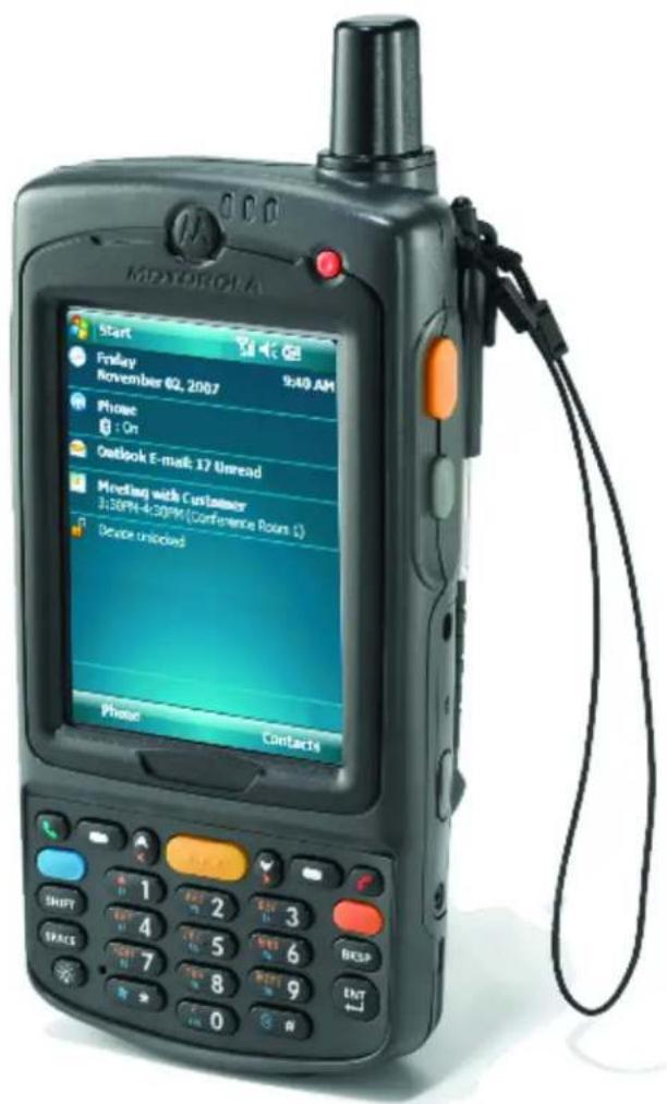
MC75 Enterprise Digital Assistant User Guide
72E-103077-02
Rev. A
August 2008
© 2008 by Motorola, Inc. All rights reserved.
No part of this publication may be reproduced or used in any form, or by any electrical or mechanical means, without permission in writing from Motorola. This includes electronic or mechanical means, such as photocopying, recording, or information storage and retrieval systems. The material in this manual is subject to change without notice.
The software is provided strictly on an “as is” basis. All software, including firmware, furnished to the user is on a licensed basis. Motorola grants to the user a non-transferable and non-exclusive license to use each software or firmware program delivered hereunder (licensed program). Except as noted below, such license may not be assigned, sublicensed, or otherwise transferred by the user without prior written consent of Motorola. No right to copy a licensed program in whole or in part is granted, except as permitted under copyright law. The user shall not modify, merge, or incorporate any form or portion of a licensed program with other program material, create a derivative work from a licensed program, or use a licensed program in a network without written permission from Motorola. The user agrees to maintain Motorola’s copyright notice on the licensed programs delivered hereunder, and to include the same on any authorized copies it makes, in whole or in part. The user agrees not to decompile, disassemble, decode, or reverse engineer any licensed program delivered to the user or any portion thereof.
Motorola reserves the right to make changes to any software or product to improve reliability, function, or design.
Motorola does not assume any product liability arising out of, or in connection with, the application or use of any product, circuit, or application described herein.
No license is granted, either expressly or by implication, estoppel, or otherwise under any Motorola, Inc., intellectual property rights. An implied license only exists for equipment, circuits, and subsystems contained in Motorola products.
MOTOROLA and the Stylized M Logo and Symbol and the Symbol logo are registered in the US Patent & Trademark Office. Bluetooth is a registered trademark of Bluetooth SIG. Microsoft, Windows and ActiveSync are either registered trademarks or trademarks of Microsoft Corporation. All other product or service names are the property of their respective owners.
Motorola, Inc.
One Motorola Plaza
Holtsville, New York 11742-1300
http://www.motorola.com/enterprisemobility
Patents
This product is covered by one or more of the patents listed on the website: http://www.motorola.com/enterprisemobility/patents.
Revision History
Changes to the original manual are listed below:
| Change Date Description | ||
| -01 Rev. A 6/10/08 Initial release | ||
| -02 Rev. A 08/14/08 Add re-boot | after installing SIM card. Add dual line SIM support. | |
iv MC75 User Guide
Table of Contents
Patents.... ii
Revision History...... iii
About This Guide
Introduction xi
Documentation Set xi
Configurations....xii
Software Versions xii
Chapter Descriptions ...... xv
Notational Conventions.... xv
Related Documents ...... xvi
Service Information...... xvi
Chapter 1: Getting Started
Introduction 1-1
Unpacking 1-2
Getting Started 1-4
Installing the SIM Card 1-4
Charging the Battery 1-7
Charging the Main Battery and Memory Backup Battery 1-7
Charging Spare Batteries 1-8
Charging Temperature 1-8
Powering On the MC75 1-8
Calibrating the Screen 1-8
Checking Battery Status 1-8
Adjusting the Handstrap 1-10
Removing the Screen Protector 1-10
Replacing the Main Battery 1-11
Changing the Power Settings 1-12
Changing the Backlight Settings 1-12
Changing the Keypad Backlight Settings 1-12
Turning Off the Radios 1-13
Chapter 2: Using the MC75
Introduction 2-1
Today Screen 2-1
Status Icons 2-2
Programs 2-4
Settings 2-7
Battery Status Indications 2-10
Battery Reserve Options 2-11
Main Battery Temperature Notifications 2-12
Performing a Warm Boot 2-14
Performing a Cold Boot 2-14
Waking the MC75 2-14
Locking the MC75 2-15
Numeric Keypad Configuration 2-16
Alpha-numeric Keypad Configurations 2-19
Special Character Key 2-26
Function Buttons 2-27
Stylus 2-28
Entering Data 2-28
Linear Scanning 2-29
Imaging 2-29
Operational Modes 2-29
Digital Camera 2-30
Scanning Considerations 2-30
Linear Scanning 2-30
Imager Scanning 2-31
Digital Camera Scanning 2-32
Taking Photos 2-33
Viewing Photos and Videos 2-34
Using IrDA 2-34
Infrared Connection 2-35
Exchanging Files using IR Connection 2-35
Chapter 3: Using GPS Navigation
Introduction 3-1
Software Installation 3-1
MC75 GPS Setup 3-1
Operation 3-2
GPS Maps on microSD Cards 3-2
Answering a Phone Call While Using GPS 3-2
Losing the GPS Signal While in a Vehicle 3-2
Assisted GPS 3-2
Chapter 4: Using Bluetooth
Introduction 4-1
Adaptive Frequency Hopping 4-1
Security 4-2
Disabling Bluetooth 4-3
Enabling Bluetooth 4-3
Bluetooth Power States 4-4
Cold Boot 4-4
Warm Boot 4-4
Suspend 4-4
Resume 4-4
Modes 4-4
Wizard Mode 4-4
Explorer Mode 4-4
Available Services 4-9
File Transfer Services 4-9
Creating a New File or Folder 4-10
Deleting a File 4-11
Getting a File 4-11
Copying a File 4-11
Connecting to the Internet Using an Access Point 4-11
Dial-Up Networking Services 4-12
Object Exchange Push Services 4-12
Sending a Contact 4-13
Swapping Contacts 4-14
Fetching a Contact 4-15
Sending a Picture 4-15
Headset Services 4-16
Hands-free Services 4-17
Serial Port Services 4-18
ActiveSync Using Serial Port Services 4-18
Personal Area Network Services 4-20
IrMC Synchronization Services 4-20
Bonding with Discovered Device(s) 4-20
Deleting a Bonded Device 4-22
Accepting a Bond 4-22
Bluetooth Settings 4-23
Device Info Tab 4-23
Services Tab 4-23
Dial-Up Networking Service 4-24
File Transfer Service 4-25
Hands-Free Audio Gateway Service 4-26
Headset Audio Gateway Service 4-26
IrMC Synchronization Service 4-26
OBEX Object Push Service 4-27
Personal Area Networking Service 4-28
Serial Port Service 4-29
Security Tab 4-29
Discovery Tab 4-30
Virtual COM Port Tab 4-31
HID Tab 4-32
Profiles Tab 4-32
System Parameters Tab 4-33
Miscellaneous Tab 4-33
Chapter 5: Using the Phone
Introduction 5-1
Accessing the Phone Keypad 5-1
Turning the Phone On and Off 5-2
Using a Wired Headset 5-3
Using a Bluetooth Headset 5-4
Adjusting Audio Volume 5-4
Making a Call 5-5
Using the Phone 5-5
Using Contacts 5-5
Using Call History 5-6
Making a Speed Dial Call 5-6
Making an Emergency Call 5-7
Answering a Call 5-7
Incoming Call Features 5-8
Smart Dialing 5-8
Muting a Call 5-9
Taking Notes 5-10
Using Speed Dial 5-11
Adding a Speed Dial Entry 5-11
Editing a Speed Dial Entry 5-13
Deleting a Speed Dial Entry 5-14
Using Call History 5-15
Managing Call History 5-15
Changing the Call History View 5-15
Resetting the Recent Calls Counter 5-15
Deleting Call History Items by Call Date 5-16
Deleting All Call History Items 5-17
Viewing Call Status 5-18
Using the Call History Menu 5-18
Swapping Calls on an MC7506/96 5-19
Swapping Calls on an MC7508/98 5-20
Conference Calling on an MC7506/96 5-20
Three-way Calling on an MC7508/98 5-22
Text Messaging 5-23
Viewing Text Messages 5-23
Sending a Text Message 5-24
Using a Dual Line SIM 5-26
Chapter 6: Accessories
Introduction 6-1
Single Slot USB/Serial Cradle 6-2
Charging the MC75 Battery 6-2
Charging the Spare Battery 6-3
Battery Charging Indicators 6-3
Charging Temperature 6-3
Four Slot Ethernet Cradle 6-4
Charging 6-4
Battery Charging Indicators 6-4
Charging Temperature 6-4
Charging 6-5
Battery Charging Indicators 6-5
Charging Temperature 6-5
Charging the MC75 Battery 6-6
Removing the MC75 6-6
Charging the Spare Battery 6-7
Battery Charging Indicators 6-8
Charging Temperature 6-8
MC75 Battery Shim Installation 6-9
Spare Battery Charging 6-9
Battery Charging Indicators 6-10
Charging Temperature 6-10
Attaching and Removing the MSR 6-11
Using the MSR 6-11
Getting Started 6-13
Installation 6-13
Removal 6-13
Credit Card Transactions 6-14
Debit Card Transactions 6-14
Keypad 6-15
Display Messages 6-16
Check the DCR Battery Level 6-16
Battery Charging and Operating Power 6-19
LED Charge Indications 6-20
Charging Temperature 6-20
Chapter 7: Maintenance & Troubleshooting
Introduction 7-1
Maintaining the MC75 7-1
Battery Safety Guidelines 7-2
Cleaning 7-3
Materials Required 7-3
Cleaning the MC75 7-3
Housing 7-3
Display 7-3
Scanner Exit Window 7-3
Connector 7-3
Cleaning Cradle Connectors 7-4
Cleaning Frequency 7-4
Troubleshooting 7-5
MC75 7-5
Bluetooth Connection 7-7
Single Slot USB/Serial Cradle 7-8
Four Slot Ethernet Cradle 7-10
Vehicle Cradle 7-11
Four Slot Battery Charger 7-12
Cables 7-12
Magnetic Stripe Reader 7-13
Appendix A: Technical Specifications
MC75 Technical Specifications ...... A-1
MC75 A-1
Single Slot USB/Serial Cradle A-6
Four Slot Ethernet Cradle A-6
Four Slot Charge Only Cradle A-7
Four Slot Battery Charger A-7
Magnetic Stripe Reader A-8
Appendix B: Voice Quality Manager
Introduction B-1
Features B-1
Enabling VQM B-1
Audio Modes B-2
Changing Audio Modes B-2
Voice Packet Prioritization B-4
Acoustic Echo Cancellation B-4
Limitations B-4
Disabling VQM B-4
Glossary
Index
About This Guide
Introduction
This guide provides information about using the MC75 Enterprise Digital Assistant (EDA) and accessories.

NOTE Screens and windows pictured in this guide are samples and can differ from actual screens.
Documentation Set
The documentation set for the MC75 provides information for specific user needs, and includes:
- MC75 Quick Start Guide - describes how to get the MC75 EDA up and running.
• MC75 User Guide - describes how to use the MC75 EDA. - MC75 Integrator Guide - describes how to set up the MC75 EDA and accessories.
- Microsoft® Windows Mobile 6.0 Applications User Guide for Enterprise Mobility Devices - describes how to use Microsoft developed applications.
- Enterprise Mobility Application Guide - describes how to use Enterprise Mobility developed sample applications.
- Enterprise Mobility Developer Kit (EMDK) Help File - provides API information for writing applications.
Configurations
This guide covers the following configurations:
| Configuration | Radios Display Memory | Data Capture | Operating System | Keypads | ||
| MC7506 WPAN: | BluetoothWWAN: HSDPAGPS: SiRF III | 3.5" VGA Color | 128 MB RAM/256 MB Flash | 1D laser scanner, 2D imager or camera | Windows Mobile 6 Professional | Numeric or Alphanumeric keypad |
| MC7508 WPAN: | BluetoothWWAN: EVDOGPS: SiRF III | 3.5" VGA Color | 128 MB RAM/256 MB Flash | 1D laser scanner, 2D imager or camera | Windows Mobile 6 Professional | Numeric or Alphanumeric keypad |
| MC7596 WLAN: | 802.11a/b/gWPAN: BluetoothWWAN: HSDPAGPS: SiRF III | 3.5" VGA Color | 128 MB RAM/256 MB Flash | 1D laser scanner, 2D imager or camera | Windows Mobile 6 Professional | Numeric or Alphanumeric keypad |
| MC7598 WLAN: | 802.11a/b/gWPAN: BluetoothWWAN: EVDOGPS: SiRF III | 3.5" VGA Color | 128 MB RAM/256 MB Flash | 1D laser scanner, 2D imager or camera | Windows Mobile 6 Professional | Numeric or Alphanumeric keypad |
Software Versions
This guide covers various software configurations and references are made to operating system or software versions for:
• Adaptation Kit Update (AKU) version
- OEM version
- Phone version
- BTExplorer version
- Fusion version
- Phone version.
AKU Version
To determine the Adaptation Kit Update (AKU) version:
Tap Start > Settings > System tab > About icon > Version tab.
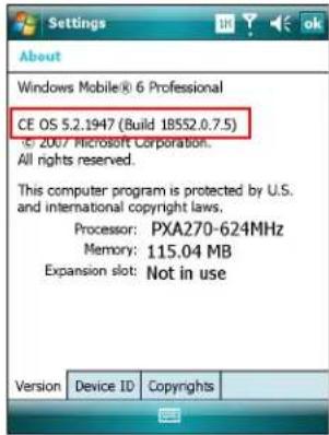
The second line lists the operating system version and the build number. The last part of the build number represents the AKU number. For example, Build 18552.0.7.5 indicates that the device is running AKU version 0.7.5.
OEM Version
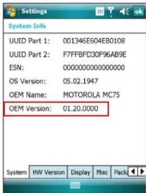
To determine the OEM software version:
Tap Start > Settings > System tab > System Info icon > System tab.
BTExplorer Software
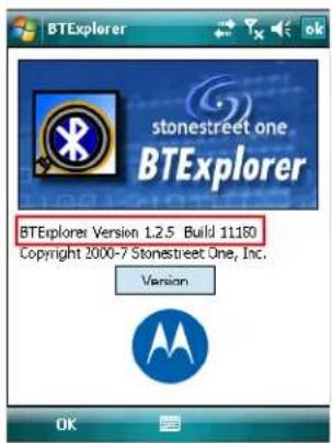
To determine the BTExplorer software version:
Tap BTExplorer icon > Show BTExplorer> Menu > About.

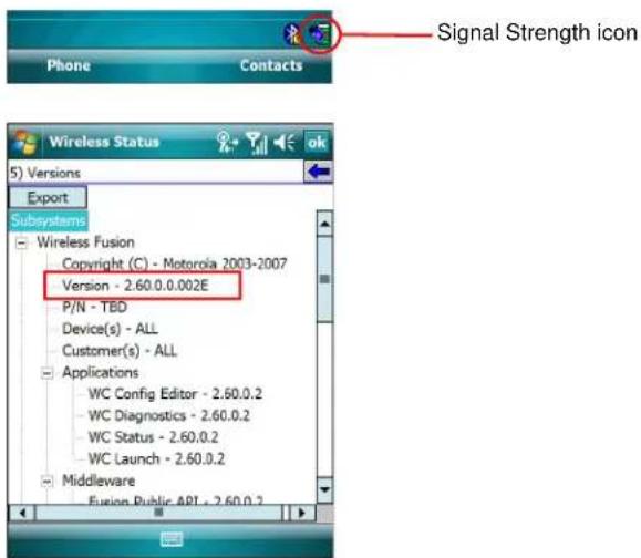
Fusion Software
To determine the Fusion software version:
Tap Signal Strength icon > Wireless Status > Versions.
Phone Software
To determine the Phone software version:
Tap Start > Phone > Menu > Options > Phone Info or Version Information tab.
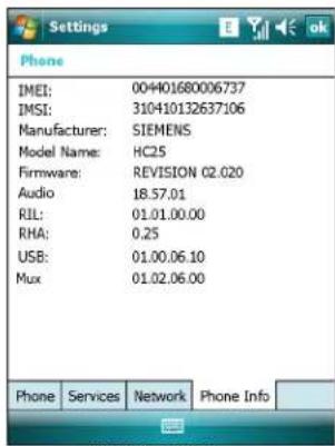
MC7506/96
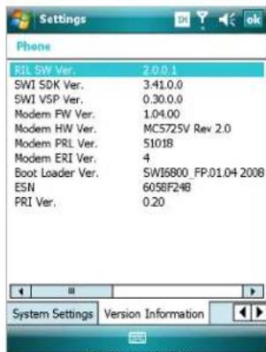
MC7508/98
Chapter Descriptions
Topics covered in this guide are as follows:
• Chapter 1, Getting Started provides information on getting the MC75 up and running for the first time.
• Chapter 2, Using the MC75 provides basic instructions for using the MC75, including powering on and resetting the MC75, and entering and capturing data.
• Chapter 3, Using GPS Navigation provides information about GPS navigation with the MC75.
• Chapter 4, Using Bluetooth explains Bluetooth functionality on the MC75.
• Chapter 5, Using the Phone provides basic instructions for using the MC75 phone.
• Chapter 6, Accessories describes the available accessories and how to use them with the MC75.
- Chapter 7, Maintenance & Troubleshooting includes instructions on cleaning and storing the MC75, and provides troubleshooting solutions for potential problems during MC75 operation.
- Appendix A, Technical Specifications provides the technical specifications for the MC75.
- Appendix B, Voice Quality Manager provides inflammation on using the Voice Quality Manager software.
Notational Conventions
The following conventions are used in this document:
- "EDA" refers to the Motorola MC75 series of hand-held computers.
• Italics are used to highlight the following:
• Chapters and sections in this and related documents
- Icons on a screen.
- Bold text is used to highlight the following:
- Dialog box, window, and screen names
- Drop-down list and list box names
- Check box and radio button names
• Key names on a keypad - Button names on a screen.
- bullets (•) indicate:
- Action items
- Lists of alternatives
- Lists of required steps that are not necessarily sequential
- Sequential lists (e.g., those that describe step-by-step procedures) appear as numbered lists.
Related Documents
• MC75 Quick Start Guide, p/n 72-103079-xx.
• MC75 Windows Mobile 6 Regulatory Guide, p/n 72-103080-xx.
• MC75 Integrator Guide, p/n 72E-103078-xx.
- Microsoft® Applications for Mobile 6 User Guide, p/n 72E-108299-xx
• Enterprise Mobility Application Guide, p/n 72E-68901-xx
- Enterprise Mobility Developer Kits (EMDKs), available at: http://www.motorola.com/enterprisemobility/support.
- Latest ActiveSync software, available at: http://www.microsoft.com.
For the latest version of this guide and all guides, go to: http://www.motorola.com/enterprisemobility/manuals.
Service Information
If you have a problem with your equipment, contact Motorola Enterprise Mobility support for your region. Contact information is available at: http://www.motorola.com/enterprisemobility/contactsupport.
When contacting Enterprise Mobility support, please have the following information available:
- Serial number of the unit
• Model number or product name - Software type and version number
Motorola responds to calls by email, telephone or fax within the time limits set forth in support agreements.
If your problem cannot be solved by Motorola Enterprise Mobility Support, you may need to return your equipment for servicing and will be given specific directions. Motorola is not responsible for any damages incurred during shipment if the approved shipping container is not used. Shipping the units improperly can possibly void the warranty.
If you purchased your Enterprise Mobility business product from a Motorola business partner, contact that business partner for support.
xviii MC75 User Guide
Chapter 1 Getting Started
Introduction
This chapter lists the parts and accessories for the MC75 and explains how to install and charge the batteries, replace the strap, and power on the MC75 for the first time.
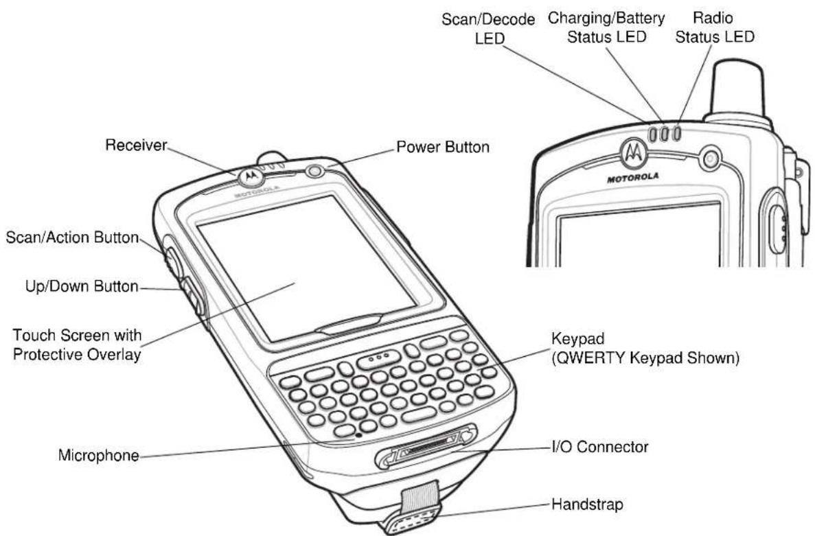
Figure 1-1 MC75 Front View
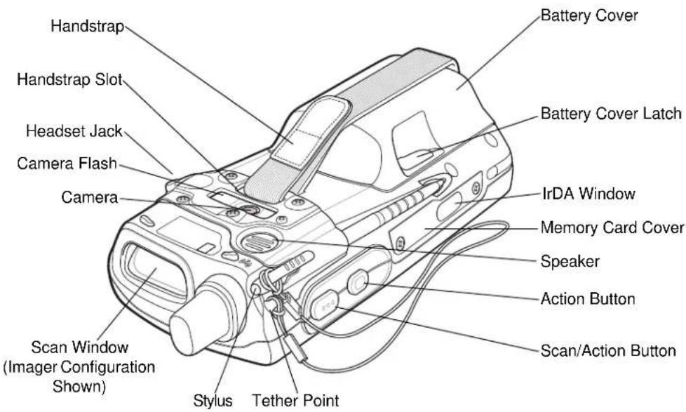
Figure 1-2 MC75 Rear View
Unpacking
Carefully remove all protective material from the MC75 and save the shipping container for later storage and shipping.
Verify that you received the following:
- MC75 EDA
• 3600 mAh Lithium-ion battery - Battery cover/strap assembly
- Tethered stylus
- Protective overlay, installed on display window
• Regulatory Guide - Quick Start Guide.
Inspect the equipment for damage. If any equipment is missing or damaged, contact the Motorola Enterprise Mobility Support center immediately. See page xvi for contact information.
Accessories
Table 1-1 lists the accessories available for the MC75.
Table 1-1 MC75 Accessories
| Accessory Part Number Description | ||
| Cradles | ||
| Single Slot USB/Serial Cradle | CRD7X00-1000RR Charges | the MC75 main battery and a spare battery. Synchronizes the MC75 with a host computer through a USB connection. |
| Four Slot Ethernet Cradle | CRD7000-4000ER | Charges the MC75 main battery and connects the MC75 with an Ethernet network. |
| Four Slot Charge Only Cradle | CRD7X00-4000CR Charges | up to four MC75 devices. |
| VCD7000 Vehicle Cradle | VCD7X00-P000R | Installs in a vehicle and charges the MC75 main battery and a spare battery. Provides serial data communication between an MC75 and an external device. |
| Chargers | ||
| Four Slot Battery Charger S | AC7X00-4000CR Charges | up to four MC75 spare batteries. Includes an MC75 shim. |
| Serial Charging Cable 25-10 | 2776-01R Provides power | to the MC75 and serial communication with a host computer. |
| USB Charging Cable | 25-102775-01R Provides | power to the MC75 and USB communication with a host computer. |
| Charge Only Cable | 25-95214-02R | Provides power to the MC75. |
| Auto Charge Cable | 25-70979-01R | Charges the MC75 using a vehicle's cigarette lighter. |
| Cables | ||
| DEX Cable | 25-76793-01R | Connects the MC75 to a vending machine. |
| Modem Inverter Cables | 25-70924-03R | Modem inverter cable. |
| O'Neil Printer Cable | 25-91519-01R | Printer cable for O'Neil printers. |
| Zebra Printer Cable | 25-91518-01R | Printer cable Zebra Road Warrior printers. |
| Zebra Printer Cable | 25-91515-01R | Printer cable for Zebra QL printers. |
| Miscellaneous | ||
| Magnetic Stripe Reader (MSR) | MSR7000-100R | Snaps on to the MC75 and adds magstripe read capabilities. |
| Modem Dongle | MDM9000-100R | Provides modem connectivity. |
| Spare 3600 mAh lithium-ion battery | BTRY-MC7XEAB00 | Replacement 3600 mAh battery. |
| Spare 4800 mAh lithium-ion battery | BTRY-MC7XEAB0H | Optional 4800 mAh battery. |
| Accessory | Part Number | Description |
| Battery Kit for 3600 mAh battery | BTRY-KT-1R5X-MC7XR | Replacement 3600 mAh battery and battery door. |
| Battery Kit for 4800 mAh battery | BTRY-KT-2R5X-MC7XR | Replacement 4800 mAh battery and battery door. |
| Headset 50-11300-050R Use in noisy environments. | ||
| Belt Mounted Rigid Holster SG-MC70011110-01R Clips onto belt to hold the MC75 when not in use. | ||
| Fabric Holster SG-MC7521215-01R Soft holder for added protection. | ||
| Stylus Stylus-00002-03R Replacement stylus (3-pack). | ||
| Wall Mounting Kit | 8710-050006-01R | Use for wall mounting the four slot cradles. |
| Screen Protector | KT-67525-01R | Package of 3 screen protectors. |
| Software | - | Enterprise Mobility Developer Kits (EMDKs), available at: http://support.symbol.com. |
Getting Started
To start using the MC75 for the first time:
• Install the SIM card (MC7506 and MC7596 only)
• Install the main battery.
- Charge the MC75.
• Power on the MC75.
- Configure the MC75.
Installing the SIM Card

NOTE MC7506 and MC7596 configurations only.
GSM phone service requires a Subscriber Identification Module (SIM) card, or smart card. Obtain this card from the your service provider. The card fits into the MC75 and can contain the following information:
- Mobile phone service provider account details.
• Information regarding service access and preferences. - Contact information, which can be moved to Contacts on the MC75.
- Any additional services to which you have subscribed.

NOTE For more information about SIM cards, refer to the service provider's documentation.
To install the SIM card:
- Lift the SIM cover using the stylus tip.
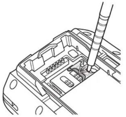
natural_image
Technical line drawing of a mechanical component with a tool inserted, showing internal parts and mounting holes (no text or symbols)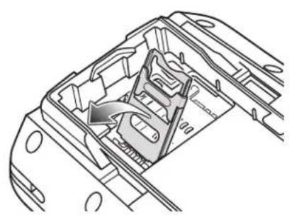
natural_image
Technical line drawing of a mechanical component with internal structure and directional arrow (no text or symbols)Figure 1-3 Lifting the SIM Cover
- Insert the SIM card, as shown in Figure 1-4, with the cut edge of the card facing out and the contacts facing down.
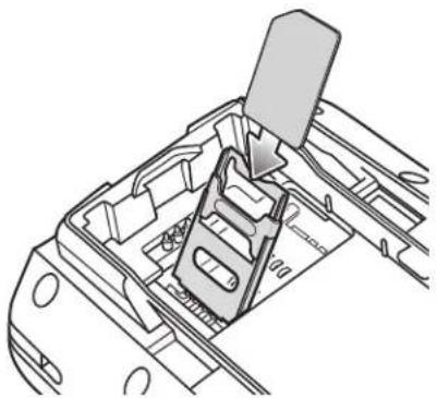
natural_image
Technical line drawing of a mechanical component with a clamping mechanism (no text or symbols)Figure 1-4 Inserting the SIM Card
- Lower the SIM cover and using the stylus tip, slide it in place.
- Install the battery. See Installing the Main Battery on page 1-6 for more information.
- After completing initial MC75 setup or after replacing a SIM card:
a. Press the red Power button.
b. On the Today screen, tap Wireless Manager.
c. Ensure Phone is on.
d. Press the red Power button to suspend the MC75.
e. Perform a warm boot. See Resetting the MC75 on page 2-14.
f. Make a call to verify cellular connection.

NOTE For detailed information about WWAN activation and settings, refer to the MC75 Integrator Guide.
Installing the Main Battery

NOTE The MC75 ships with a 3600 mAh battery. An optional 4800 mAh battery is available.
To install the main battery:
- Insert the battery, top first, into the battery compartment in the back of the MC75.

NOTE Position the battery correctly, with the battery charging contacts on top of the charging contacts in the battery compartment.
- Press the battery down into the battery compartment until the battery release latch snaps into place.
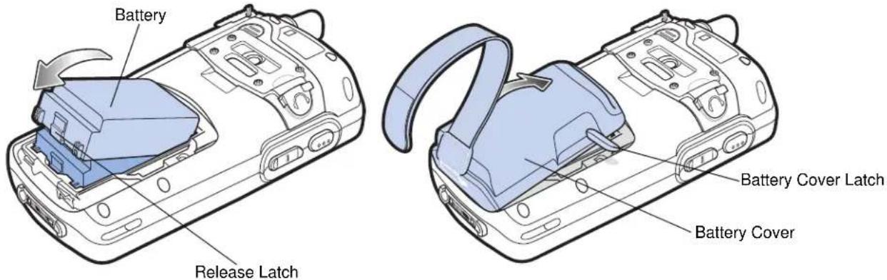
Figure 1-5 Inserting the Battery
- With the battery cover latches open, insert the cover, bottom first, then press down on the top of the cover.
- Close the battery cover latches on either side of the battery cover.
- Insert the handstrap through the handstrap slot, then tighten and press down to secure.
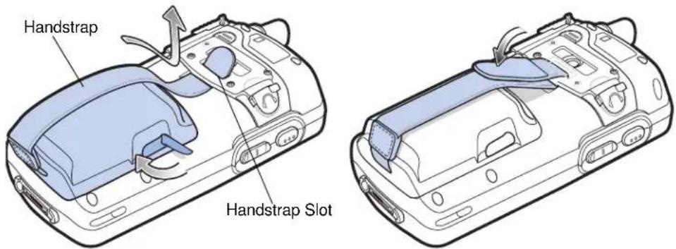
Figure 1-6 Inserting the Handstrap
The MC75 powers up after inserting the battery and replacing the battery cover.
Charging the Battery
CAUTION Ensure that you follow the guidelines for battery safety described in Battery Safety Guidelines on page 7-2.
Charging the Main Battery and Memory Backup Battery
Before using the MC75 for the first time, charge the main battery until the amber Charging/Battery Status LED remains lit (see Table 1-2 on page 1-7 for charge status indications). To charge the MC75, use a cable or a cradle with the appropriate power supply. For information about the accessories available for the MC75, see Chapter 6, Accessories.
The MC75 is equipped with a memory backup battery which automatically charges from the fully-charged main battery. When using the MC75 for the first time, the backup battery requires approximately 36 hours to fully charge. This is also true any time the backup battery is discharged, which occurs when the main battery is removed for several hours. The backup battery retains RAM data in memory for at least 15 minutes (at room temperature) when the MC75's main battery is removed. When the MC75 reaches a very low battery state, the combination of main battery and backup battery retains RAM data in memory for at least 48 hours.
To charge the main battery, use either a charging cable or a cradle. For cable and cradle setup and charging procedures refer to the MC75 Integrator Guide.
• Single Slot USB/Serial Cradle
• Four Slot Ethernet Cradle
• Four Slot Charge Only Cradle
- Vehicle Cradle.
To charge the main battery:
- Connect the charging accessory to the appropriate power source.
- Insert the MC75 into a cradle or attach to a cable. The MC75 begins charging. The Charging/Battery Status LED blinks amber while charging, then turns solid amber when fully charged. See Table 1-2 for charging indications.
The 3600 mAh battery fully charges in approximately five hours and the 4800 mAh battery charges in approximately seven hours.
Table 1-2 LED Charge Indicators
| Off MC75 is not charging. | MC75 is not inserted correctly in the cradle or connected to a power source.Charger/cradle is not powered. |
| Slow Blinking Amber(1 blink every 2 seconds) | MC75 is charging. |
| Solid Amber Charging complete. | Note: When the battery is initially inserted in the MC75, the amber LED flashes once if the battery power is low or the battery is not fully inserted. |
| Fast Blinking Amber(2 blinks/second) | Charging error, e.g.:Temperature is too low or too high.Charging has gone on too long without completion (typically eight hours). |
| Charging/Battery Status LED | Indication |
| Single Blink Amber (when Power button pressed) | Battery depleted. |
| Blinking Amber (when Power button pressed) | Battery over-temperature condition. |
Charging Spare Batteries
See Chapter 6, Accessories for information on using accessories to change spare batteries.
Charging Temperature
Charge batteries in temperatures from 0^ C to 40^ C ( 32^ F to 104^ F). Charging is intelligently controlled by the MC75.
To accomplish this, for small periods of time, the MC75 or accessory alternately enables and disables battery charging to keep the battery at acceptable temperatures. The MC75 or accessory indicates when charging is disabled due to abnormal temperatures via its LED. See Table 1-2.
Powering On the MC75
Press the Power button to turn on the MC75. If the MC75 does not power on perform a warm boot. See Resetting the MC75 on page 2-14.
When turning the MC75 on for the first time, the splash screen displays for about a minute as the MC75 initializes its flash file system, then the calibration window appears. Note that these windows also appear upon cold boot.

NOTE When the MC75 powers up after inserting a battery for the first time, the device boots and powers on automatically.
Calibrating the Screen
To calibrate the screen so the cursor on the touch screen aligns with the tip of the stylus:
- Remove the stylus from its holder on the back of the MC75.
- Carefully press and briefly hold the tip of stylus on the center of each target that appears on the screen.
- Repeat as the target moves around the screen, then tap the screen to continue.
Checking Battery Status
To check the charge status of the main battery or backup battery in the MC75, tap Start > Settings > System tab > Power icon to display the Power window.
To save battery power, tap the Advanced tab and set the MC75 to turn off after a specified number of minutes.
Micro Secure Digital (microSD) Card
The microSD card slot provides secondary non-volatile storage. The slot is located on the side of the MC75 (see Figure 1-7). Refer to the documentation provided with the card for more information, and follow the manufacturer's recommendations for use.

CAUTION Follow proper ESD precautions to avoid damaging the microSD card. Proper ESD precautions include, but are not limited to, working on an ESD mat and ensuring that the operator is properly grounded.
To install the microSD card:
- Power off the MC75.
- Remove the memory card cover on the side of the MC75 by loosening the two captive screws.
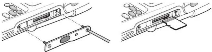
natural_image
Technical line drawing showing two views of a device handle assembly (no text or symbols)Figure 1-7 Card Installation
- Insert the card with the card contacts facing up and the cut corner on the left, until you feel a click.
- Replace the memory card cover and tighten the screws.
To remove an microSD card:
- Power off the MC75.
- Remove the memory card cover by loosening the screws.
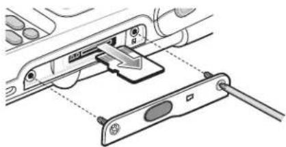
natural_image
Diagram of a device with a switch and cable inserted, showing internal components (no text or symbols)Figure 1-8 Card Removal
- Carefully press and release the card to eject it.
- Remove the card from the card slot.
- Replace the memory card cover and tighten the screws.
Adjusting the Handstrap
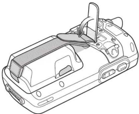
The MC75 handstrap is attached to the bottom of the battery cover. Adjust the handstrap to increase comfort when holding the MC75 for extended periods of time. To adjust the handstrap:
- Feed the handstrap through the handstrap slot in either direction, to tighten or loosen.
- Secure the handstrap by pressing the two sides together as shown in Figure 1-9.
natural_image
Line drawing of a handheld electronic device with internal components and a slide (no text or symbols)Figure 1-9 Handstrap Adjustment
Removing the Screen Protector
A screen protector is applied to the MC75. Motorola recommends using this to minimize wear and tear. Screen protectors enhance the usability and durability of touch screen displays.
To remove the screen protector, lift the corner using a thin plastic card, such as a credit card, then carefully lift it off the display.
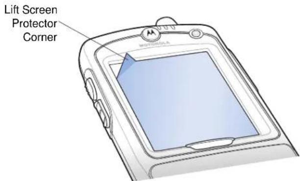
Figure 1-10 Removing the Screen Protector

CAUTION Do not use a sharp object to remove the protector. Doing so can damage the display.

NOTE Not using a screen protector can affect warranty coverage. To purchase replacement protectors, contact your local account manager or Motorola, Inc. These include screen protector installation instructions. Part number: KT-67525-01R Screen Protector 3/pk.
Replacing the Main Battery
- Press the red Power button to suspend the MC75.
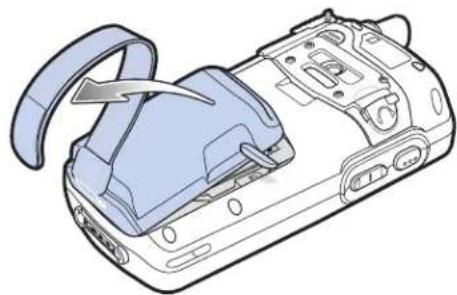
- Loosen the handstrap.
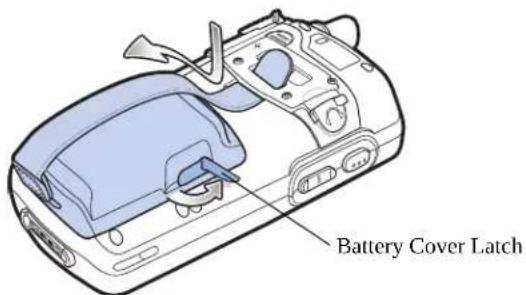
- Open the battery cover latches on either side of the battery cover.
natural_image
Diagram of a device casing with a handle and internal components, no text or symbols presentFigure 1-11 Removing the Battery Cover
- Lift the top of the battery cover and remove.
- Press the battery release latch on the bottom of the battery to unlock, and lift the battery out of the well.
- Insert the replacement battery, top first, into the battery compartment in the back of the MC75.
- Press the battery down into the battery compartment until the battery release latch snaps into place.

NOTE Position the battery correctly, with the battery charging contacts on top of the charging contacts in the battery compartment.
- With the battery cover latches open, insert the cover, bottom first, then press down on the top of the cover.
- Close the battery cover latches on either side of the battery cover.
- Insert the handstrap through the handstrap slot, then tighten and press down to secure.
The MC75 powers up after inserting the battery and replacing the battery cover.
Battery Management
Observe the following battery saving tips:

NOTE The MC75 factory default settings for the WWAN and WLAN radios are set to ON.
- Leave the MC75 connected to AC power at all times when not in use.
- Set the MC75 to turn off after a short period of non-use.
- Set the backlight to turn off after a short period of non-use.
- Turn off all wireless activities when not in use.
• Power off the MC75 when charging to charge at a faster rate.
Changing the Power Settings
To set the MC75 to turn off after a short period of non-use:
- Tap Start > Settings > System tab > Power icon > Advanced tab.
- Select the On battery power: Turn off device if not used for check box and select a value from the drop-down list.
- Select ok.
Changing the Backlight Settings
To change the backlight settings in order to conserve more battery power:
- Tap Start > Settings > System tab > Backlight icon > Battery Power tab.
- Select the Disable backlight if device is not used for check box and select a value from the drop-down list.
- Select the Brightness tab.
- Tap the Disable backlight check box to turn off the display backlight, or use the slider to set a low value for the backlight.
- Select ok.
Changing the Keypad Backlight Settings
To change the keypad backlight settings in order to conserve more battery power:
- Tap Start > Settings > System tab > Keylight icon > Battery Power tab.
- Select the On battery power: Disable keylight if device if not used for check box and select a value from the drop-down list.
- Select the Advanced tab.
- Tap the Disable keylight check box to turn off the keypad backlight.
- Select ok.
Turning Off the Radios
Windows Mobile 6 devices include Wireless Manager, which provides a simple method of enabling, disabling, and configuring all the device's wireless capabilities in one place.
To open Wireless Manager, tap the Connectivity icon or tap Wireless Manager on the Today screen.
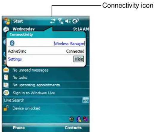
Figure 1-12 Opening Wireless Manager
Select Wireless Manager.
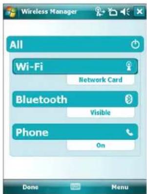
Figure 1-13 Wireless Manager Window

NOTE Wireless connection options vary depending upon configurations.
To enable or disable a wireless connection, tap the specific button.
To enable or disable all wireless connections, tap the All button.
To configure settings for a connection, tap Menu.
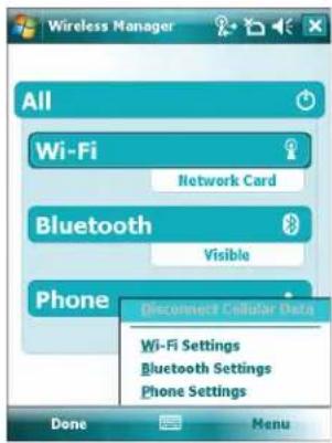
Figure 1-14 Wireless Manager Menu
Chapter 2 Using the MC75
Introduction
This chapter explains the buttons, status icons, and controls on the MC75, and provides basic instructions for using the MC75, including powering on and resetting the MC75, and entering and capturing data.
The MC75 factory default radio states are:
- Bluetooth - OFF
- Phone - ON
- Wireless LAN - ON.
Today Screen
The Today screen displays important information, such as upcoming appointments and status indicators. Tap a section on the screen to open the associated program. Alternatively, tap Start > Today to display the Today screen.
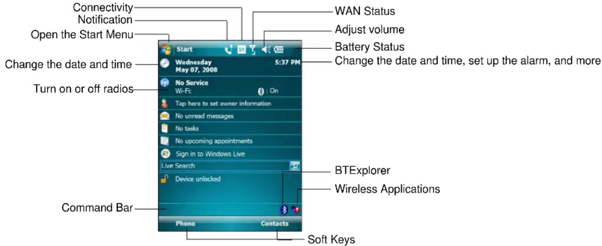
Figure 2-1 Today Screen
To customize the Today screen, tap Start > Settings > Today icon. Use the Appearance tab to customize the background and the Items tab to change the list and order of items that appear on the screen.
Status Icons
The Navigation bar at the top of the screen can contain the status icons listed in Table 2-1.
Table 2-1 Status Icons
| Icon Function Description | ||
| Notification Backup Battery Low. | ||
| Connectivity Connection is active. | ||
| WAN Call missed. | ||
| Dialing while no SIM card is installed. | ||
| Voice call in progress. | ||
| Calls are forwarded. | ||
| Call on hold. | ||
| Speakerphone is on. | ||
| Antenna/signal icon: wireless on/good signal. | ||
| Antenna/signal icon: wireless off. | ||
| Antenna/signal icon: no service or searching. | ||
| HSDPA connecting. (MC7506 and MC7596) | ||
| HSDPA in use. (MC7506 and MC7596) | ||
| 3G connecting. (MC7506 and MC7596) | ||
| 3G in use. (MC7506 and MC7596) | ||
| GPRS connecting. (MC7506 and MC7596) | ||
| GPRS in use. (MC7506 and MC7596) | ||
| EGPRS connecting. (MC7506 and MC7596) | ||
| EGPRS in use. (MC7506 and MC7596) | ||
| EVDO connecting. (MC7508 and MC7598) | ||
| EVDO in use. (MC7508 and MC7598) | ||
| Roaming. | ||
| SIM Card not installed. (MC7506 and MC7596) | ||
| Speaker All sounds are on. | ||
| Battery Main battery is charging. | ||
| Time and Next Appointment | Displays current time in analog or digital format. | |
The command bar at the bottom of the screen can contain the task tray icons listed in Table 2-2.
Table 2-2 Task Tray Icons
| Icon Description | ||
 | Wireless connection status | Indicates WLAN signal strength. |
 | Bluetooth Enabled Bluetooth radio is on. | |
 | Bluetooth Disabled Bluetooth radio is off. | |
 | Bluetooth Connection Bluetooth radio is connected to another Bluetooth device. | |
 | ActiveSync Active serial connection between the MC75 and the host computer. | |
Programs
Table 2-3 lists the default programs on the Start menu.
Table 2-3 Programs in the Start Menu
| Icon Name Description | ||
 | Office Mobile | Use the complete suite of Microsoft® Office applications for your mobile device.Excel Mobile - Create new workbooks or view and edit Microsoft®Excel® workbooks.OneNote Mobile - Create new notes or view existing notes.PowerPoint Mobile - View Microsoft® PowerPoint® slides and presentations.Word Mobile - Create, view, and edit Microsoft® Word documents. |
 | ||
| [c8GX] | Calendar Keep track of appointments and create meeting requests. | |
 | Contacts Keep track of friends and colleagues. | |
 | Internet Explorer Mobile | Browse Web and WAP sites as well as download new programs and files from the Internet. |
Table 2-3 Programs in the Start Menu
| Icon Name | Description |
 | Messaging Send and receive e-mail, MMS, and text messages. |
 | Phone Make and receive calls, switch between calls, and set up conference calling. |
 | Help See Help topics for the current screen or program. |
Table 2-4 lists programs that are listed in the Programs window.
Table 2-4 Programs in Program Window
| Icon Name Description | ||
 | ActiveSync Synchronize | information between the MC75 and a host computer or the Exchange Server. |
| Air BEAM | AirBEAM | Allows specially designed software packages to be transferred between a host server and the MC75. Refer to the MC75 Integrator Guide for more information. |
 | BTExplorer Manages Bluetooth connections. | |
 | Calculator Perform basic arithmetic and calculations, such as addition, subtraction, multiplication, and division. | |
 | File Explorer Organize and manage files on your device. | |
 | Get Good Link to download Good Mobile Messaging software. | |
 | Internet Sharing Connect a notebook computer to the Internet using the MC75's data connection. | |
 | Messenger Use this mobile version of Windows Live Messenger. | |
 | MSP Agent | Interacts with MSP agents to collect monitoring and asset information to enable the configuration, provisioning, monitoring and troubleshooting of the MC75. Refer to the MC75 Integrator Guide for more information. |
 | Notes Create handwritten or typed notes, drawings, and voice recordings. | |
 | Pictures & Videos View and manage pictures, animated GIFs, and video files. | |
 | Rapid Deployment Facilitates software downloads from a Mobility Services Platform Console FTP server to the MC75. Refer to the MC75 Integrator Guide for more information. | |
 | Remote Desktop Log onto Windows NT server type computers and use all of the programs that are available on that computer from the MC75. | |
 | Search Search contacts, data, and other information on your MC75. | |
 | SIM Toolkit Manage the contacts that are stored on your SIM card. Copy SIM contents to Contacts on the MC75. | |
 | Tasks Keep track of your tasks. | |
 | Windows Live Use this mobile version of Windows LiveTM to find information on the web. | |
 | Windows Media Player Mobile | Play back audio and video files. |
Settings
Table 2-5 lists control applications pre installed on the MC75. Tap Start > Settings to open the Settings window.
Table 2-5 Settings in the Setting Window
| Icon Name Description | ||
| Personal Tab | ||
 | Buttons Assign a program to a button. | |
 | Input Set options for each of the input methods. | |
 | Lock Set a password for the MC75. | |
 | Menus Set what programs appear in the Start menu. | |
 | Owner Information Enter personal information on the MC75. | |
 | Phone Make and receive calls, switch between calls, and set up conference calling. | |
 | Sounds & Notifications | Enable sounds for events, notifications, and more, and set the type of notification for different events. |
 | Today Customize the appearance and the information to be displayed on the Today screen. | |
| System Tab | ||
 | About | View basic information such as the Windows Mobile® version and type of processor used on the MC75. |
 | Backlight | Set the display backlight time-out and adjust brightness. |
 | Certificates | See information about certificates installed on the MC75. |
 | Clock & Alarms | Set the device clock to the date and time of your locale or to a visiting time zone when you're traveling. Alarms can also be set at specified days and times of a week. |
| Icon | Name | Description |
 | Customer Feedback Submit feedback on the Windows Mobile 6 software. | |
 | Encryption Allow files on a storage card to be encrypted. Encrypted files are readable only on your device. | |
 | Error Reporting Enable or disable the device's error reporting function. When this function is enabled and a program error occurs, technical data about the state of the program and your computer is logged in a text file and delivered to Microsoft's technical support if you choose to send it. | |
 | External GPS Set the appropriate GPS communication ports, if required. You may need to do this when there are programs on your device that access GPS data or you have connected a GPS receiver to the MC75. | |
 | GPS Setup View GPS SUPL information. | |
 | Keylight Set the keypad backlight time-out. | |
 | Memory Check the device memory allocation status and memory card information and stop currently running programs. | |
 | Power | Check battery power and set the time-out for turning off the display to conserve battery power. |
 | Regional Settings | Set the regional configuration to use, including the format for displaying numbers, currency, date, and time on the MC75. |
 | Remove Programs Remove programs that you installed on the MC75. | |
 | Screen Change the screen orientation, re-calibrate the screen, and change the screen text size. | |
 | System Info | Displays the MC75's software and hardware information. |
 | Windows Update | Link to Microsoft's web site and update Windows Mobile® on your device with the latest security patches or fixes. Do not use. Obtain updates from Motorola. |
| Icon Name Description | ||
| Connections Tab | ||
 | Beam Set the MC75 to receive incoming IrDA beams. | |
 | Connections | Set up one or more types of modem connections for your device, such as phone dial-up, GPRS, Bluetooth, and more, so that your device can connect to the Internet or a private local network. |
 | USB to PC Enables or disables the enhanced network connectivity. | |
 | Wi-Fi Setup wireless network connection and customize settings. | |
 | Wireless Manager Enables or disables the MC75's wireless radios and customizes Wi-Fi, Bluetooth and Phone settings. | |
Adjusting Volume
To adjust the system volume using the Speaker icon in the navigation bar:
- Tap the Speaker icon. The Volume dialog box appears.
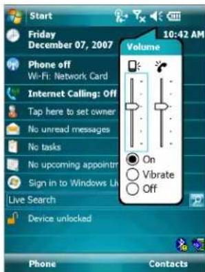
Figure 2-2 Volume Dialog Box
-
Tap and move the slide bar to adjust the volume.
-
Select the On or Off radio button to turn the volume on or off.
You can also adjust the system volume using the Sounds & Notifications window, or use the Up/Down button on the side of the MC75.
Battery Status Indications
Battery icons appear on the navigation bar indicating the battery power level. When the main battery or backup battery power falls below a predetermined level the icon indicates the status and a battery dialog box appears indicating the status of the main or backup battery.
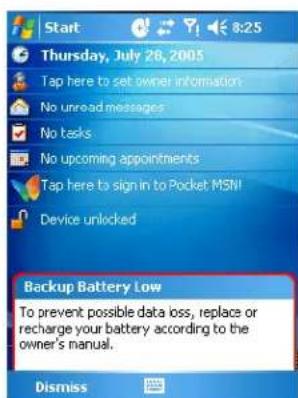
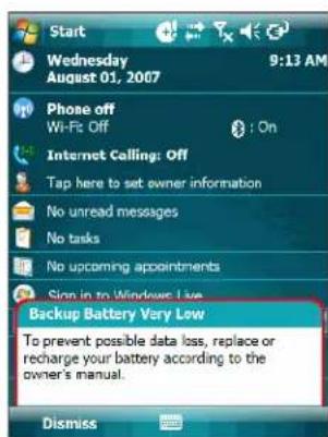
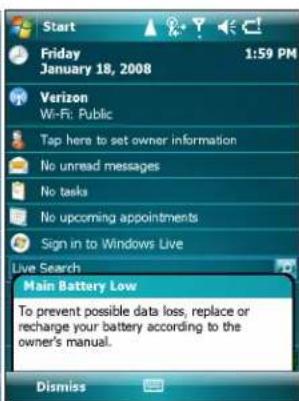
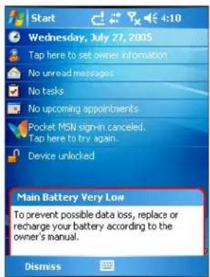
Figure 2-3 Battery Status Dialog Box
The Battery icon always appears in the navigation bar when the Today screen is visible. The icon indicates the battery power level. The message displays until the Dismiss button is pressed.

Figure 2-4 Battery Icon on the Title Bar
Also view the battery status using the Power window.
Battery Reserve Options
If the charge of the battery reaches a critical threshold, the MC75 shuts down. This threshold can be changed but affects the amount of time that data can be retained.
- Tap Start > Settings > Power icon > RunTime tab. A warning message appears.
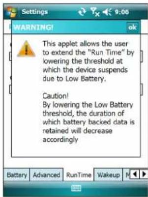
Figure 2-5 Warning Message
- Read the warning message and tap ok.
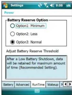
Figure 2-6 RunTime Tab
-
Select one of the Battery Reserve Options.
-
Option 1: Minimum - After a low battery shutdown, data will be retained for minimum amount of time. Battery should be replaced immediately to avoid data loss.
- Option 2: Less - After a low battery shutdown, data will be retained for less than normal amount of time.
-
Option 3: Normal - After a low battery shutdown, data will be retained for maximum amount of time.
-
Tapok.
Main Battery Temperature Notifications
The temperature notification system implements three levels of notification when the temperature within the battery exceeds specific temperature thresholds:
- Level 1: Temperature Watch; this level is similar to main battery low warning. It indicates that the battery temperature has reached the first threshold level. The user should move to an environment within proper operating temperature.
- Level 2: Temperature Warning; this level is similar to main battery very low warning. It indicates the battery temperature has reached the second threshold level. The user should stop using the MC75.
- Level 3: Temperature Error; this level indicates the battery has reached an unusable temperature threshold and immediately suspends the MC75. This level does not have any graphical notification associated with it.
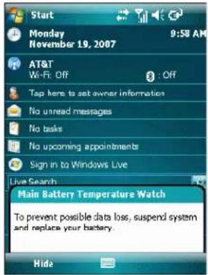
Figure 2-7 Main Battery Temperature Watch Dialog Box
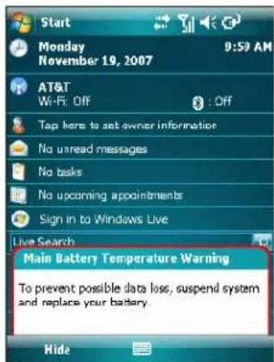
Figure 2-8 Main Battery Temperature Warning Dialog Box

NOTE The Temperature Warning dialog box remains visible until you tap Hide.
LED Indicators
The MC75 has three LED indicators. The Scan/Decode LED indicates status for bar code scanning. The Charging/Battery Status LED indicates battery charging and status. The Radio Status LED indicates WAN radio status. Table 2-6 describes the LED indications.
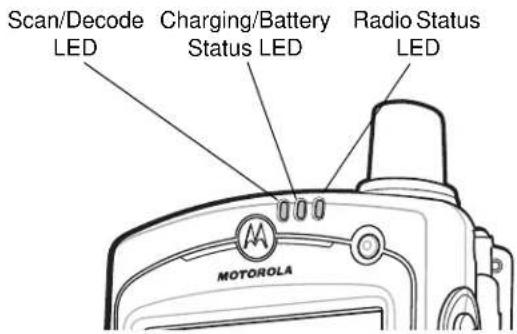
Figure 2-9 LED Indicators
Table 2-6 LED Indications
| LED State Indication | |
| Scan/Decode LED | |
| Solid Green Successful decode/capture. | |
| Solid Red Laser enabled, scanning/imaging in process. | |
| Off Not enabled. | |
| Charging/Battery Status LED | |
| Slow Blinking Amber Main battery in MC75 is charging. | |
| Solid Amber Main battery in MC75 is fully charged. | |
| Fast Blinking Amber Charging error. | |
| Off Not charging. | |
| Single Blink Amber (when Power button pressed) Battery depleted. | |
| Blinking Amber (when Power button pressed) Battery over-temperature condition. | |
| Radio Status LED | |
| Slow Blinking Green WAN radios is on. | |
| Off WAN radio is off. | |

NOTE For information about scanning/decoding, see Data Capture on page 2-29. For information about WAN radio status and settings, see Chapter 5, Using the Phone, or refer to the MC75 Integrator Guide.
Resetting the MC75
There are two reset functions, warm boot and cold boot. A warm boot restarts the MC75 by closing all running programs. A cold boot also restarts the MC75, and also resets the clock. Data saved in flash memory or a memory card is not lost.
If the MC75 is not functioning properly, perform a warm boot first. If the MC75 still does not respond, perform a cold boot.
Performing a Warm Boot
Hold down the Power button for approximately five seconds. As soon as the MC75 starts to boot release the Power button.
Performing a Cold Boot
To perform a cold boot simultaneously press the Power button and the 1 and 9 keys.
Waking the MC75
The wake-up conditions define what actions wake up the mobile computer after it has gone into suspend mode. The mobile computer can go into suspend mode by either pressing the Power button or automatically by Control Panel time-out settings. These settings are configurable and the factory default settings are shown in Table 2-7 are subject to change/update.
Table 2-7 Wake-up Default Settings
| Condition for Wake-up Power Button | Automatic Time-out | |
| AC power is applied. No Yes | ||
| Mobile computer is inserted into a cradle. No Yes | ||
| Mobile computer is removed from a cradle. No Yes | ||
| Mobile computer is connected to a USB device. No Yes | ||
| Mobile computer is disconnected from a USB device. No Yes | Yes | |
| A key is pressed. No Yes | ||
| The scan triggered is pressed. No Yes | ||
| The screen is touched. No No | ||
| Audio Jack | No No | |
| Audio Btn | No No | |
| Bluetooth communication | Yes | Yes |
| Incoming phone call | Yes | Yes |
Locking the MC75
Use the Device Lock feature to prevent use of the device. Note that when locked, the MC75 does not respond to screen or keypad input.
To lock the device, tap the Device unlocked icon. The icon changes to locked.
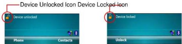
Figure 2-10 Device Locked/Unlocked Icons
To unlock the device and free it for use, tap Unlock.
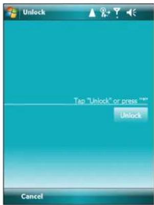
Figure 2-11 Unlock Device Window
Tap Unlock on the Unlock window.

NOTE You can make emergency calls even when the MC75 is locked. See Making an Emergency Call on page 5-7 for more information.
Keypads
The MC75 offers two types modular keypad configurations: Numeric and alpha-numeric.
Numeric Keypad Configuration
The numeric keypad contains application keys, scroll keys, and function keys. The keypad is color-coded to indicate the alternate function key (blue) values. Note that an application can change keypad functions so the MC75's keypad may not function exactly as described. See Table 2-8 for key and button descriptions and Table 2-9 on page 2-18 for the keypad's special functions.
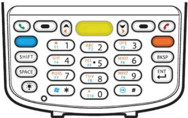
Figure 2-12 MC75 Numeric Keypad
Table 2-8 MC75 Numeric Keypad Descriptions
| Key Description | |
Blue Key (left) | Use this key to launch applications or access items (shown on the keypad in blue).Press the Blue key once to activate this mode, followed by another key.A single press displays the following icon at the bottom of the screen, until a second key is pressed:[SZDY] |
Orange Key | Use this key to access the secondary layer of characters and actions (shown on the keypad in orange). Press the Orange key once to lock the keypad into Alpha state.A single press displays the following icon at the bottom of the screen:Press the Orange key a second time to return to the normal state.Press the Orange key, then the Shift key to add a temporary shift (that applies only to the next key pressed) to the orange lock state. This displays the following icon at the bottom of the screen: |
TalkEnd  | Talk (Green Phone): press to display the phone keypad window or to dial a phone number (from the phone keypad window).End (Red Phone): press when the phone keypad window displays to stop dialing or end a call. |
Scan (yellow) | Activates the scanner/imager in a scan enabled application. |
Scroll Up and Down | Moves up one item.Moves left one item when pressed with the Orange key. |
Scroll Left and Right | Moves down one item.Moves right one item when pressed with the Orange key. |
Soft Keys | Accesses the command or menu above it on the screen. |
Star | Produces an asterisk in default state.Press and release the blue key, then press the Star key to open the Start menu. |
Alphanumeric    | In default state, produces the numeric value on the key.In Alpha state, produces the lower case alphabetic characters on the key. Each key press produces the next alphabetic character in sequence. For example, press and release the Orange key and then press the '4' key once to produce the letter 'g'; press and release the Orange key and then press the '4' key three times to produce the letter 'i'.Press the SHIFT key in Alpha state to produce the upper case alphabetic characters on the key. For example, press and release the Orange key, press and release the SHIFT key, and then press the '4' key once to produce the letter 'G'; press and release the Orange key, press and release the SHIFT key and then press the '4' key three times to produce the letter 'I'. |
SPACE | Produces a space. |
| BACKSPACE[WASW] | Produces a backspace. |
| Key | Description |
SHIFT | Press and release the SHIFT key to activate the keypad alternate SHIFT functions.A single press displays the following icon at the bottom of the screen, until a second key is pressed:[KSSS]Press the Orange key, then the Shift key to add a temporary shift (that applies only to the next key pressed) to the orange lock state. This displays the following icon at the bottom of the screen:[IMAGE] |
ENT (Enter) | Executes a selected item or function. |
Pound | Produces a pound/number sign.Press and release the blue key, then press the Pound key to produce an OK. |
Table 2-9 Numeric Keypad Input Modes
| Key | Numeric Mode | Orange Key(Alpha Lowercase Mode) | Orange + Shift Keys(Alpha Uppercase Mode) | ||||||||
| Blue+ Key | SHIFT + Key | 1st Press | 2nd Press | 3rd Press | 4th Press | 1st Press | 2nd Press | 3rd Press | 4th Press | ||
| 1 | 1 | F | 1 | ! | * | * | * | * | * | ||
| 2 | 2 | F | 2 | @ a | b | c | A | B | |||
| 3 | 3 | F | 3 | # d | e | f | D | E | F | ||
| 4 | 4 | F4 | $ | g | h | i | G | H | I | ||
| 5 | 5 | F | 5 | % j | k | l | J | K | L | ||
| 6 | 6 | F6 | ^ | m | n | o | M | N | O | ||
| 7 | 7 | F | 7 | & p | q | r | s | P | Q | ||
| 8 | 8 | F8 | * | t | u | v | T | U | V | ||
| 9 | 9 | F | 9 | ( w | x | y | z | W | X | Y | |
| 0 | 0 | F | 1 | 0 ) | . | > | |||||
| Up Up | Up Hilight | Up | Left Left | ||||||||
| Down | Down Down | Hilight | Down | Right Right | |||||||
| Enter | Action Action | Action | Action | Action | |||||||
| Note: An application can change the key functions. The keypad may not function exactly as described. | |||||||||||
Alpha-numeric Keypad Configurations
The three types of alpha-numeric keypads produce the 26-character alphabet (A-Z, both lowercase and uppercase), numbers (0-9), and assorted characters. The keypad is color-coded to indicate which modifier key to press to produce a particular character or action. The keypad default is alphabetic, producing lowercase letters. See Table 2-10 for key and button descriptions and Table 2-11 on page 2-22 for the keypad's special functions.
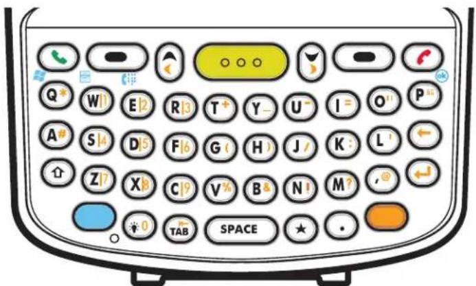
Figure 2-13 QWERTY Keypad Configuration
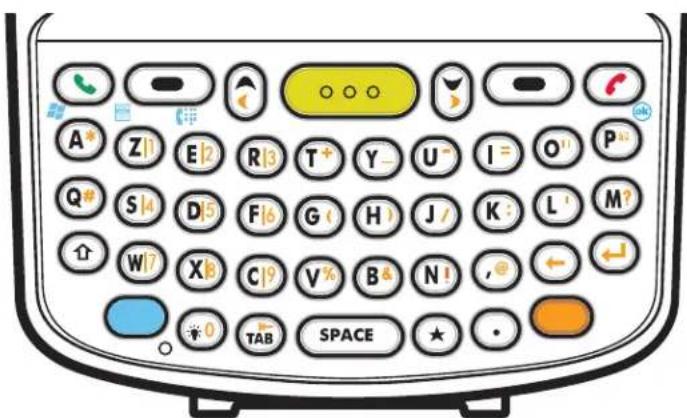
Figure 2-14 AZERTY Keypad Configuration
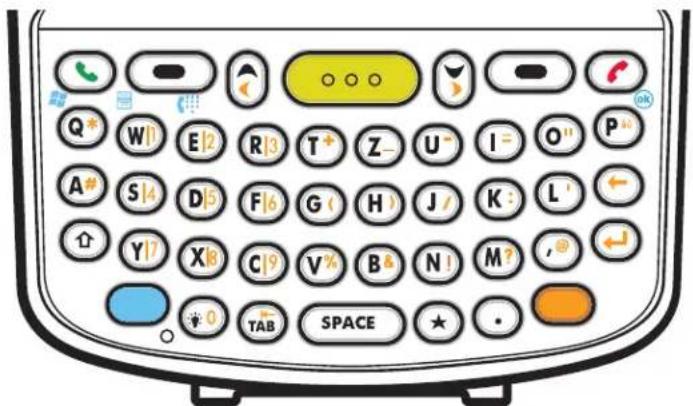
Figure 2-15 QWERTZ Keypad Configuration
Table 2-10 Alpha-numeric Keypad Descriptions
| Key Action | |
Blue Key Launches applications (shown on the keypad in blue). | Press the Blue key once to activate this mode temporarily, followed by another key. This displays the following icon at the bottom of the screen, until a second key ispressed: Press the Blue key twice to lock this mode. This displays the following icon at the bottom of the screen: Press the Blue key twice to lock this mode. This displays the following icon at the bottom of the screen: Press the Blue key a third time to unlock.Press and hold the Blue key while selecting a sequence of keys to activate this mode temporarily. This displays the following icon at the bottom of the screen as long as the key is pressed:[IMAGE] Press the Blue key a third time to unlock.Press and hold the Blue key while selecting a sequence of keys to activate this mode temporarily. This displays the following icon at the bottom of the screen as long as the key is pressed:[IMAGE] |
Orange Key Accesses the secondary layer of characters and actions (shown on the keypad in orange). | Press the Orange key once to activate this mode temporarily, followed by another key.This displays the following icon at the bottom of the screen, until a second key ispressed:[YHA2]Press the Orange key twice to lock this mode. This displays the following icon at the bottom of the screen:[HABD]Press the Orange key a third time to unlock.Press and hold the Orange key while selecting a sequence of keys to activate this mode temporarily. This displays the following icon at the bottom of the screen as long as the key is pressed:[XTA2] |
Talk/End Talk (Green Phone): press to display the phone keypad window or to dial a phone number [J3DW] [J3DW] | Press when the phone keypad window displays to stop dialing or end a call. |
Scroll Up and Left Moves | up one item.Moves left one item when pressed with the Orange key. |
Scroll Down and Right Moves | Moves down one item.Moves right one item when pressed with the Orange key. |
Soft Keys | Accesses the command or menu above it on the screen. |
| Shift[WYST] | Changes the state of the alpha characters from lowercase to uppercase.Press the Shift key to activate this mode temporarily, followed by another key.This displays the following icon at the bottom of the screen, until a second key ispressed: ↑Press the Shift key twice to lock this mode. This displays the following icon at thebottom of the screen: ↑Press the Shift key a third time to unlock. |
Backlight Turns the display backlight on and off. | |
Backspace Produces a backspace. | |
Enter Executes a selected item or function. | |
Star Produces an asterisk. | |
OK Use this key in conjunction with the Blue key as an OK or close button. This function isuser programmable. | |
Start Menu | Use this key in conjunction with the Blue key to instantly display the Start menu from anyapplication without tapping the screen. This function is user programmable. |
| Key | Action |
| Menu Use this key in conjunction with the Blue key to instantly display the context menu from any application without tapping the screen. This function is user programmable. | |
| Phonepad | Use this key in conjunction with the Blue key to display the Phonepad application without tapping the screen. This function is user programmable. |
Table 2-11 QWERTY Keypad Input Modes
| Key | Normal | Shift + Key | Orange + Key | Blue + Key |
| Q | q Q | * | S | t |
| W | w | W | 1 | |
| E e | E 2 | Phone | ||
| R | r | R | 3 | |
| T | t | T | + | |
| Y | y | Y | - | |
| U | u | U | - | |
| I | i | I | = | |
| O | o | O | “ | |
| P | p | P | áü | |
| A | a | A | # | |
| S | s | S | 4 | |
| D | d | D | 5 | |
| F | f | F | 6 | |
| G | g | G | ( | |
| H | h | H | ) | |
| J | j | J | / | |
| K | k | K | : | |
| L | l | L | ‘ | |
| Backspace | Backspace | |||
| Shift | Shift | |||
| Z | z | Z | 7 | |
| X | x | X | 8 | |
| C | c | C | 9 | |
| V | v | V | % | |
| B | b | B | & | |
| N | n | N | ! | |
| M | m | M | ? | |
| , | , | < | @ | |
| ENTER Enter | ||||
| Backlight Backlight Backlight 0 Backlight | ||||
| TAB Tab Tab | Back tab | Tab | ||
| SPACE | Space | Space | Space | Space |
| Star | * | * | * | * |
| . | . | > | . | . |
Note: An application can change the key functions. The keypad may not function exactly as described.
Table 2-12 AZERTY Keypad Input Modes
| Key | Normal | Shift + Key | Orange + Key | Blue + Key |
| A | a | A | * | Start Menu |
| Z | z | Z | 1 | |
| E | e | E | 2 Phone | |
| R | r | R | 3 | |
| T | t | T | + | |
| Y | y | Y | - | |
| U | u | U | - | |
| I | i | I | = | |
| O | o | O | “ | |
| P | p | P | áü | |
| Q | q | Q | # | |
| S | s | S | 4 | |
| D | d | D | 5 | |
| F | f | F | 6 | |
| G | g | G | ( | |
| H | h | H | ) | |
| J | j | J | / | |
| K | k | K | : | |
| L | l | L | ' | |
| M | m | M | ? | |
| Shift Shift | ||||
| W | w | W | 7 | |
| X | x | X | 8 | |
| C | c | C | 9 | |
| V | v | V | % | |
| B | b | B | & | |
| N | n | N | ! | |
| , | , | < | @ | |
| Backspace backspace | ||||
| Enter Enter | ||||
| Backlight Backlight Backlight 0 | Backlight | |||
| TAB | Tab | Tab | Back tab | Tab |
| SPACE | Space | Space | Space | Space |
| Star | * | * | * | * |
| . | . | > | . | . |
Note: An application can change the key functions. The keypad may not function exactly as described.
Table 2-13 QWERTZ Keypad Input Modes
| Key | Normal | Shift + Key | Orange + Key | Blue + Key |
| Q | q | Q | * | Start Menu |
| W | w | W | 1 | |
| E | e | E | 2 | Phone |
| R | r | R | 3 | |
| T | t | T | + | |
| Z | z | Z | - | |
| U | u | U | - | |
| I | i | I | = | |
| O | o | O | “ | |
| P | p | P | á | |
| A | a | A | # | |
| S | s | S | 4 | |
| D | d | D | 5 | |
| F | f | F | 6 | |
| G | g | G | ( | |
| H | h | H | ) | |
| J | j | J | / | |
| K | k | K | : | |
| L | l | L | ‘ | |
| Backspace Backspace | ||||
| Shift Shift | ||||
| Y | y | Y | 7 | |
| X | x | X | 8 | |
| C | c | C | 9 | |
| V | v | V | % | |
| B | b | B | & | |
| N | n | N | ! | |
| M | m | M | ? | |
| , | , | < | @ | |
| ENTER Enter | ||||
| Backlight | Backlight | Backlight | 0 | Backlight |
| TAB | Tab | Tab | Back tab | Tab |
| SPACE Space Space | Space Space | |||
| Star**** | ||||
| . | . | > | . | . |
Note: An application can change the key functions. The keypad may not function exactly as described.
Special Character Key

NOTE Special characters are only available on the alpha-numeric keypad configurations.
To add special characters using the MC75 äü key, type the related character first, then press the Orange twice followed by the äü (P) key. Continue pressing the äü key until the special character displays. To modify an existing character, move the cursor to the right of the character then press the Orange key twice and then press the äü key until the special character replaces the original character. Table 2-14 lists the special characters you can generate.
Table 2-14 Special Characters
| Key | Special Characters | Key | Special Characters | |
| a | à á à ä å a ̃ a æ | A | A À Á Á Á Á Á Á Á Á Á | |
| c | ç c č © | C | çóč© | |
| d | ã | D | Đ | |
| e | è é è è e | E | È É Ê Ê Ê Ê | |
| i | ì í î i | I | ì í î î | |
| l | ł | L | L Ł | |
| n | ñ | N | Ñ | |
| o | ò ó ô ô ô ó ó ó | O | ò ó ô ô ô ó ó ó ó | |
| p | þ ¶ | P | þ ¶ | |
| r | ® | R | ® | |
| s | ş š B | S | ş š B | |
| t | ṭ | T | ṭ | |
| u | ù ú ú ú ú | U | ù ú ú ú ú ú | |
| y | ý | Y | ý | |
| z | ź z | Z | ź z | |
| $ | € £ ¥ | / | \ | | |
| “ | ‘« ‘» | ( | [ { < « | |
| ) | ] } > » | + | ± & - _ | |
| Key Special Characters Key Special Characters | ||||
| ! | i ? ¿ | . | ; , ; | |
| * | # | @ | ~ % | |
| % | ^ | , | ; . : | |
| # | * | & | - _ + ± | |
| - | + ± & - | ' | « » " | |
| ? | ¿ ! i | : | , ; . | |
| - | _ + ± & | |||
Function Buttons
The MC75's buttons perform certain functions.
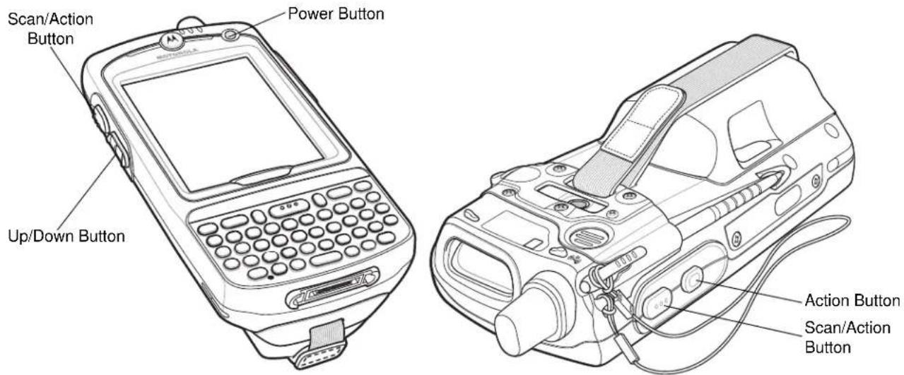
Figure 2-16 Function Buttons
- Power: Press the red Power button to turn the MC75 screen on and off. The MC75 is in suspend mode when the screen is off. For more information, see Powering On the MC75 on page 1-8. Also use the Power button to reset the MC75 by performing a warm or cold boot. See Resetting the MC75 on page 2-14.
- Scan/Action: Press to scan bar codes or capture images. See Data Capture on page 2-29. Or, press to open an application or perform a function. See the Microsoft® Applications for Mobile 6 User Guide to set an application to open.
- Up/Down: Press to increase or decrease the MC75's volume.
- Action: Press to open an application or perform a function. See the Microsoft® Applications for Mobile 6 User Guide to set an application to open.
Stylus
Use the MC75 stylus to select items and enter information. The stylus functions as a mouse.
- Tap: Touch the screen once with the stylus to press option buttons and open menu items.
- Tap and Hold: Tap and hold the stylus on an item to see a list of actions available for that item. On the pop-up menu that appears, tap the action to perform.
- Drag: Hold the stylus on the screen and drag across the screen to select text and images. Drag in a list to select multiple items.

NOTE Motorola recommends using the spring-loaded tip of the stylus to write on the screen, and the back end of the stylus to tap the screen. Use your finger to press the Power button and keypad buttons.

CAUTION To prevent damage to the screen, do not use any device other than the Motorola-provided stylus.
Entering Data
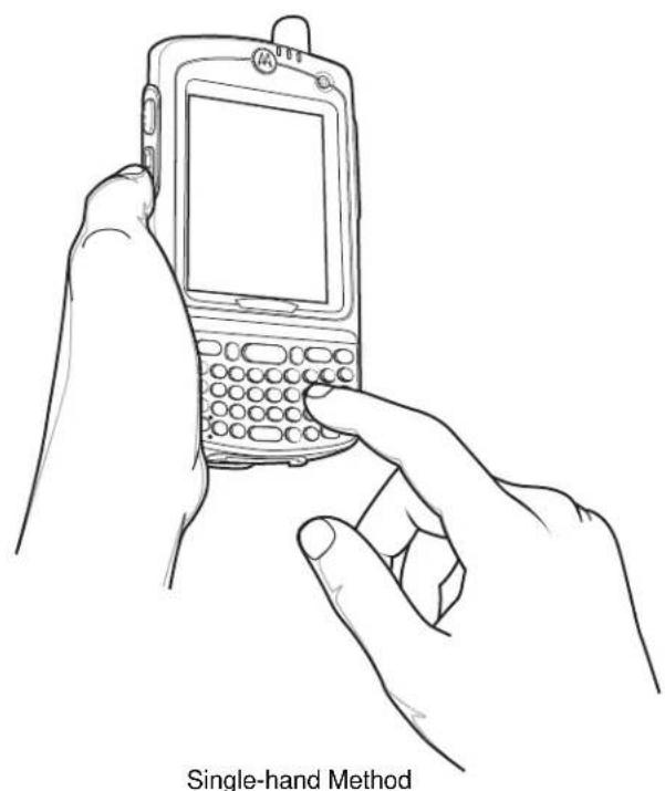
When entering data on the keypad, use either the single-hand method or the two-hand method as shown in Figure 2-17.
natural_image
Line drawing of two hands holding a single-hand mobile phone, no text or symbols present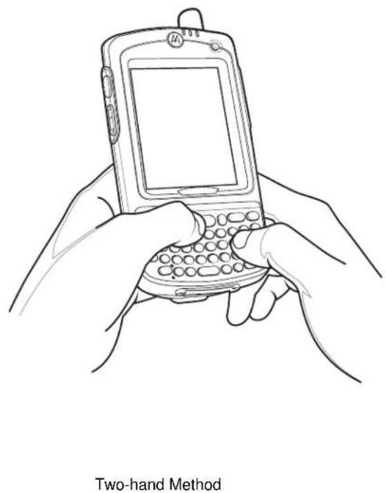
natural_image
Line drawing of two hands using a handheld mobile phone to press a keyboard (no text or symbols on device)Figure 2-17 Entering Data on the Keypad
Data Capture
The MC75 offers three types of data capture options:
- Linear scanning
- Imaging
- Digital camera.

NOTE To perform data capture a scanning enabled application must be installed on the MC75. A sample scanning application can be downloaded from the Motorola Support site at http://support.symbol.com.
Linear Scanning
MC75 with an integrated linear scanner have the following features:
- Reading of a variety of bar code symbologies, including the most popular linear, postal, and 1-D code types.
- Intuitive aiming for easy point-and-shoot operation.
Imaging
MC75 with an integrated imager have the following features:
- Omnidirectional reading of a variety of bar code symbologies, including the most popular linear, postal, PDF417, and 2D matrix code types.
- The ability to capture and download images to a host for a variety of imaging applications.
- Advanced intuitive laser aiming for easy point-and-shoot operation.
The imager uses digital camera technology to take a digital picture of a bar code, stores the resulting image in its memory, and executes state-of-the-art software decoding algorithms to extract the data from the image.
Operational Modes
MC75 with an integrated imager support three modes of operation, listed below. Activate each mode by pulling the trigger or pressing the Scan button.
- Decode Mode: In this mode, the MC75 attempts to locate and decode enabled bar codes within its field of view. The imager remains in this mode as long as you hold the trigger, or until it decodes a bar code.

NOTE To enable Pick List Mode, download the Control Panel applet from the web site at http://support.symbol.com. Pick List can also be set in an application using a API command.
- Pick List Mode: This mode allows you to selectively decode a bar code when more than one bar code is in the MC75's field of view. To accomplish this, move the aiming crosshair over the required bar code to decode only this bar code. This feature is ideal for pick lists containing multiple bar codes and manufacturing or transport labels containing more than one bar code type (either 1D or 2D).
- Image Capture Mode: Use this mode to capture an image within the MC75's field of view. This is useful for capturing signatures or images of items like damaged boxes.
Digital Camera
MC75 with an integrated digital camera have the following features:
- Omnidirectional reading of a variety of bar code symbologies, including the most popular linear, postal, PDF417, and 2D matrix code types.
- Advanced intuitive aiming for easy point-and-shoot operation.
The camera uses digital camera technology to take a digital picture of a bar code, stores the resulting image in its memory, and executes state-of-the-art software decoding algorithms to extract the data from the image.
Scanning Considerations
Typically, scanning is a simple matter of aim, scan, and decode and a few quick trial efforts master it. However, consider the following to optimize scanning performance:
- Range
Any scanning device decodes well over a particular working range — minimum and maximum distances from the bar code. This range varies according to bar code density and scanning device optics.
Scanning within range brings quick and constant decodes; scanning too close or too far away prevents decodes. Move the scanner closer and further away to find the right working range for the bar codes being scanned.
- Angle
Scanning angle is important for promoting quick decodes. When laser beams reflect directly back into the scanner from the bar code, this specular reflection can “blind” the scanner.
To avoid this, scan the bar code so that the beam does not bounce directly back. But don't scan at too sharp an angle; the scanner needs to collect scattered reflections from the scan to make a successful decode.
Practice quickly shows what tolerances to work within.
- Hold the MC75 farther away for larger symbols.
- Move the MC75 closer for symbols with bars that are close together.

NOTE Scanning procedures depend on the application and MC75 configuration. An application may use different scanning procedures from the one listed above.
Linear Scanning
- Ensure that a scan enabled application is loaded on the MC75.
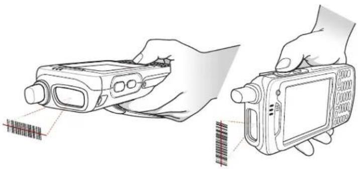
- Aim the scan window at the bar code.
natural_image
Line drawing of two hands holding a handheld device with a grid pattern, no text or symbols presentFigure 2-18 Linear Scanning
- Press the scan button. Ensure the red scan beam covers the entire bar code. The Scan/Decode LED lights red to indicate that scanning is in process, then lights green and a beep sounds, by default, to indicate the bar code was decoded successfully.
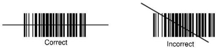
Figure 2-19 Linear Scanner Aiming Pattern
Imager Scanning
- Ensure that a scan-enabled application is loaded on the MC75.
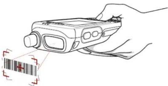
- Aim the scan window at the bar code.
natural_image
Line drawing of a hand holding a handheld device with a barcode symbol below (no text or labels)Figure 2-20 Imager Scanning
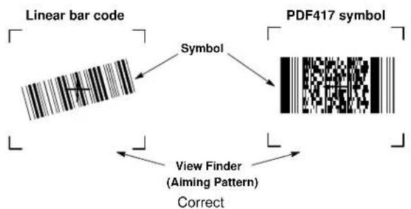
- Press the scan button. The red laser aiming pattern turns on to assist in aiming. Ensure the bar code is within the area formed by the brackets in the aiming pattern. The Scan/Decode LED lights red to indicate that scanning is in process, then lights green and a beep sounds, by default, to indicate the bar code was decoded successfully. Note that when the MC75 is in Pick List Mode, the imager does not decode the bar code until the crosshair touches the bar code.
flowchart
graph TD
    A["Linear bar code"] --> B["Symbol"]
    C["PDF417 symbol"] --> D["Symbol"]
    E["View Finder\n(Aiming Pattern)\nCorrect"] --> F["Symbol"]
    B --> G["PDF417 symbol"]
    D --> H["PDF417 symbol"]
    F --> I["PDF417 symbol"]
Figure 2-21 Imager Aiming Pattern: Bar Code Centered
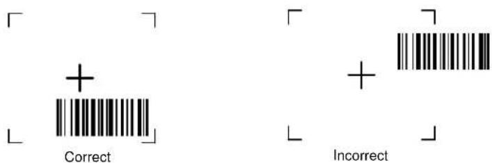
Figure 2-22 Imager Aiming Pattern: Bar Code Not Centered
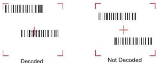
Figure 2-23 Pick List Mode with Multiple Bar Codes in Aiming Pattern
- Release the scan button.

NOTE Imager decoding usually occurs instantaneously. The MC75 repeats the steps required to take a digital picture (image) of a poor or difficult bar code as long as the scan button remains pressed.
Digital Camera Scanning
- Ensure that a scan-enabled application is loaded on the MC75.
- Aim the camera lens on the back of the MC75 at a bar code.
- Press and hold the scan button. A preview window appears on the display window with a red aiming reticle in the center. The Scan/Decode LED lights red to indicate that scanning is in process.
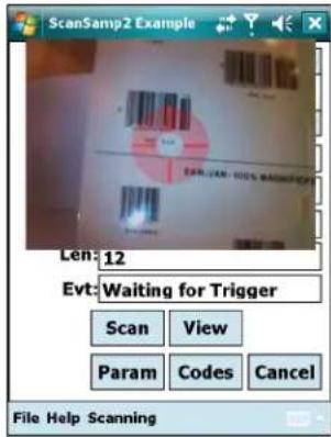
Figure 2-24 Sample Scan Application with Preview Window
- Move the MC75 until the red aiming reticle is on the bar code to scan. The aiming reticle turns green when the MC75 is able to decode the bar code.
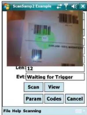
Figure 2-25 Digital Camera Scanning
- Release the scan button. The Scan/Decode LED lights green and a beep sounds, by default, to indicate the bar code was decoded successfully.
Taking Photos
To take a photo:
- Tap Start > Programs > Pictures & Videos icon.
- Tap Camera on the command bar.
- Check the image on the view finder, adjust if necessary.
- Press the Enter key to take the picture. Hold the MC75 still until the camera flash occurs or the shutter sound is heard.
Recording Video
To record a video clip:
- Tap Start > Programs > Pictures & Videos icon.
- Tap Camera on the command bar.
- Tap Menu > Video to set shooting mode to video.
The available recording time displays on the screen.

NOTE By default, the time limit for recording videos is set to 30 seconds.
- Press the Enter key to begin recording.
Recording stops when you press the Enter button again.
Viewing Photos and Videos

NOTE For detailed information on the Photos and Videos, refer to the Microsoft Applications User Guide for Mobile 6, p/n 72E-108299-xx.
To view photos and video clips:
- Tap Start > Programs > Pictures & Videos icon.
- Tap the picture or video clip to view.
Using IrDA
In a Microsoft Windows Mobile program (except Messaging), and Picture & Videos, you can exchange files using either infrared or Bluetooth.

NOTE You can also beam files (not folders) from the File Explorer window. Tap and hold the item you want to send, then tap Beam File from the pop-up menu.
First activate the beam function before exchanging files with another IrDA device.
To activate the Beam function:
- Tap Start > Settings > Connections tab > Beam icon.
- Tap Receive all incoming beams check box.
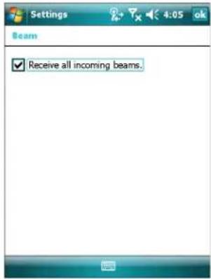
Figure 2-26 Beam Window
- Tapok.
Infrared Connection
Using infrared, you can enable short-range file exchange between your MC75 and another IrDA device.
Exchanging Files using IR Connection
Ensure that the IrDA function on both the MC75 and the other device are enabled.
To send files via IrDA connection:
- Switch to the program where you created the item you want to send and locate the item in the list.

NOTE Do not cover or block the IrDA window.
- Align the IrDA port of the MC75 with that of the IrDA device so that they are unobstructed and within a close range.
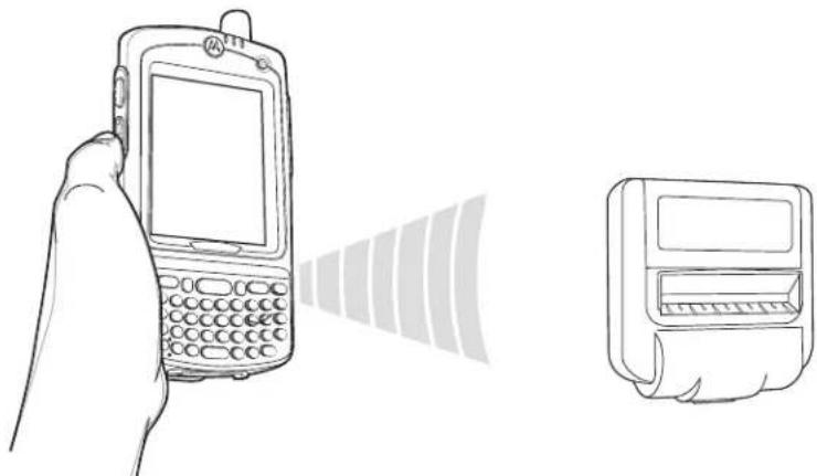
natural_image
Line drawing of a hand holding a portable phone with a screen, next to an open receipt device (no text or symbols)Figure 2-27 Align MC75 with IrDA Device
-
Tap and hold the item, then tap Beam [type of item] on the pop-up menu.
-
Tap the device that you want to send the file to.
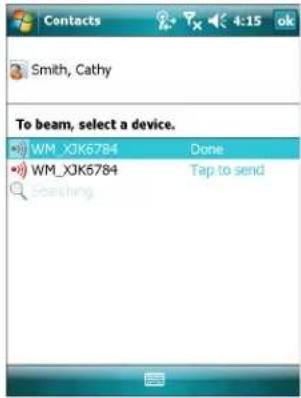
Figure 2-28 Beam Contact
To receive files via IrDA connection:
- Align the IrDA port of the MC75 with that of the other IrDA device so that they are unobstructed and within a close range.
- On the other device, send the file to the MC75.
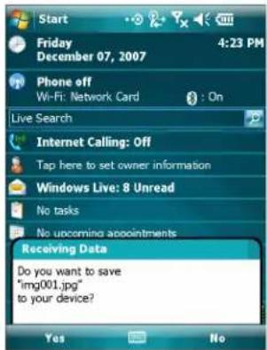
Figure 2-29 Receive File
- When the Receiving Data dialog displays, tap Yes.
Chapter 3 Using GPS Navigation
Introduction
The MC75 includes Global Positioning System (GPS) technology using the SiRF III chipset. GPS technology is based on a worldwide system of GPS satellites orbiting the earth that continuously transmit digital radio signals. These radio signals contain data on the satellites' locations and their exact clock time and are used to determine your location on the earth.

WARNING!
When using the MC75 in a vehicle, it is the user's responsibility to place, secure and use in a manner that will not cause accidents, personal injury or property damage or obstruct their view. It is the responsibility of the driver to operate the vehicle in a safe manner, maintain observation of all driving conditions at all times, and not become distracted by the device to the exclusion of safe driving practices. It is unsafe to operate the controls of the device while driving.
Software Installation
Third-party GPS navigation software is required. Evaluation software is available from various suppliers. For example; VisualGPS, visit: http://www.visualgps.net/VisualGPSce/
If interested in purchasing GPS navigation software check with the GPS software vendor (before purchasing, downloading, or installing any software) to determine that the application is compatible with the MC75. Refer to the application's user guide for application installation and setup information.
MC75 GPS Setup
The GPS-enabled MC75 uses Microsoft Windows Mobile 6, so the operating system automatically manages access to the GPS receiver to allow multiple programs to simultaneously access GPS data.
Ensure that the following settings are set on the MC75:
- Tap Start > Settings > System > External GPS icon.
- In the Programs tab, select None from the GPS program port drop-down list.
-
In the Hardware tab, select COM8 in the GPS hardware port drop-down list.
-
Select 57600 from the Baud rate drop-down list.
- Tap ok to close the Setting window.

NOTE If an application error message appears indicating that the COM port cannot be opened, ensure that a free COM port is selected in the GPS hardware port drop-down list.
Operation
Acquiring satellite signals may take a few minutes. It is best to be outside and have a clear, unobstructed view of the sky. Without a clear view, acquisition takes much longer and could result in the MC75 being unable to compute the initial position quickly. When operating the device indoors access to the GPS signals may be limited or unavailable.

NOTE When using a GPS navigation application, ensure that the MC75 does not go into suspend mode. If the MC75 suspends then the power to the GPS radio is removed. Upon resume the GPS receiver must reacquire a valid GPS signal, resulting in a delay of positional information.
GPS Maps on microSD Cards
GPS navigation software vendors may sell maps on microSD cards. If using a microSD card with the GPS navigation software:
- Remove the Memory Card Cover on the side of the MC75.
- Insert the microSD card into the slot.
- Replace the Memory Card Cover.
Answering a Phone Call While Using GPS
If you receive a phone call while using your GPS navigation software:
- Answer the phone call by pressing the Answer button.
- Once you end the phone call, press the End Call button to resume the audio on the GPS software.

NOTE Anytime you are using GPS on the MC75 and you receive a phone call, the audio on the GPS navigation software is muted until you finish the call.
Losing the GPS Signal While in a Vehicle
GPS performance on the MC75 may be affected if the vehicle has thermal glass windows and windshields, which can block the MC75 from receiving a GPS signal from satellites. To improve GPS signal strength, place the MC75 where there is a clear view of the sky. A direct line of sight is required between the MC75 and the GPS satellites to access information from the satellites.
The Global Positioning System (GPS) is a system that allows the user to track their position anywhere on the earth.
Assisted GPS
GPS can be used in stand-alone or Assisted GPS (A-GPS) modes. A Stand-alone GPS receiver downloads data from GPS satellites. It can take several minutes to get a fix. By using GPS Location servers, A-GPS dramatically
improves the performance of the Time To First Fix (TTFF) of GPS receivers by providing them with data that they would ordinarily have to download from the GPS satellites. With the A-GPS data, GPS receivers can operate faster and more reliably.
A-GPS follows the Secure User Plane Location (SUPL) protocol which allows the MC75 to communicate with a location server. Refer to the EMDK Help file for information on setting up SUPL on the MC75.
3 - 4 MC75 User Guide
Chapter 4 Using Bluetooth
Introduction
Bluetooth-equipped devices can communicate without wires, using frequency-hopping spread spectrum (FHSS) radio frequency (RF) to transmit and receive data in the 2.4 GHz Industry Scientific and Medical (ISM) band (802.15.1). Bluetooth wireless technology is specifically designed for short-range (30 feet/10 meters) communication and low power consumption.
MC75s with Bluetooth capabilities can exchange information (e.g., files, appointments, and tasks) with other Bluetooth enabled devices such as phones, printers, access points, and other mobile computers. To use the MC75 as a modem, create a dial-up modem connection between a computer and MC75.
Motorola mobile computers with Bluetooth technology use the StoneStreet Bluetooth stack. To program Bluetooth within the MC75 refer to the Enterprise Mobility Developer Kit (EMDK) Help.
Adaptive Frequency Hopping
Adaptive Frequency Hopping (AFH) is a method of avoiding fixed frequency interferers, and can be used with Bluetooth voice. All devices in the piconet (Bluetooth network) must be AFH-capable in order for AFH to work. There is no AFH when connecting and discovering devices. Avoid making Bluetooth connections and discoveries during critical 802.11b communications. AFH for Bluetooth consists of four main sections:
- Channel Classification - A method of detecting an interference on a channel-by-channel basis, or pre-defined channel mask.
- Link Management - Coordinates and distributes the AFH information to the rest of the Bluetooth network.
- Hop Sequence Modification - Avoids interference by selectively reducing the number of hopping channels.
- Channel Maintenance - A method for periodically re-evaluating the channels.
When AFH is enabled, the Bluetooth radio “hops around” (instead of through) the 802.11b high-rate channels. AFH coexistence allows Motorola mobile computers to operate in any infrastructure.
The Bluetooth radio in this MC75 operates as a Class 2 device power class. The maximum output power is 2.5mW and the expected range is 32.8 feet (10 meters). A definition of ranges based on power class is difficult to obtain due to power and device differences, and whether one measures open space or closed office space.

NOTE It is not recommended to perform Bluetooth wireless technology inquiry when high rate 802.11b operation is required.
Security
The current Bluetooth specification defines security at the link level. Application-level security is not specified. This allows application developers to define security mechanisms tailored to their specific need. Link-level security occurs between devices, not users, while application-level security can be implemented on a per-user basis. The Bluetooth specification defines security algorithms and procedures needed to authenticate devices, and if needed, encrypt the data flowing on the link between the devices. Device authentication is a mandatory feature of Bluetooth while link encryption is optional.
Pairing of Bluetooth devices is accomplished by creating an initialization key that is used to authenticate the devices and create a link key for them. Entering a common PIN number in the devices being paired generates the initialization key. The PIN number is never sent over the air. By default, the Bluetooth stack responds with no key when a key is requested (it is up to user to respond to the key request event). Authentication of Bluetooth devices is based-upon a challenge-response transaction. Bluetooth allows for a PIN number or passkey that is used to create other 128-bit keys used for security and encryption. The encryption key is derived from the link key used to authenticate the pairing devices. Also worthy of note is the limited range and fast frequency hopping of the Bluetooth radios that makes long-distance eavesdropping difficult.
Recommendations are:
• Perform pairing in a secure environment
- Keep PIN codes private and don't store the PIN codes in the mobile computer
- Implement application-level security.
Turning the Bluetooth Radio Mode On and Off
Turn off the Bluetooth radio to save power or if entering an area with radio restrictions (e.g., an airplane). When the radio is off, other Bluetooth devices cannot see or connect to the MC75. Turn on the Bluetooth radio to exchange information with other Bluetooth devices (within range). Communicate only with Bluetooth radios in close proximity.

NOTE To achieve the best battery life turn off radios not in use.
Disabling Bluetooth
To disable Bluetooth, tap Bluetooth icon > Disable Bluetooth. The Bluetooth icon changes to indicate that Bluetooth is disabled.
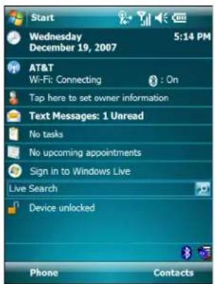
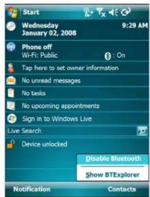
Figure 4-1 Disable Bluetooth
Enabling Bluetooth
To enable Bluetooth, tap Bluetooth icon > Enable Bluetooth. The Bluetooth icon changes to indicate that Bluetooth is enabled.
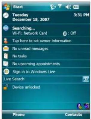
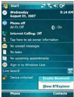
Figure 4-2 Enable Bluetooth
Bluetooth Power States
Cold Boot
Performing a cold boot on the MC75 turns off Bluetooth after initialization (which takes a few moments). It is normal to see the Bluetooth icon appear and disappear, as well as a wait cursor, when initialization proceeds in all modes.
Warm Boot
Performing a warm boot on the MC75 returns Bluetooth to the last state after initialization.
Suspend
Suspending the MC75 turns off Bluetooth.

NOTE If there is an active Bluetooth connection between the MC75 and another Bluetooth device, the MC75 will not timeout. However, if the user presses the Power button on the MC75, the MC75 will suspend and upon receiving data from a remote Bluetooth device, the MC75 will wake from suspend mode. For example, headset redial or Bluetooth scanner sending data to the MC75.
Resume
When the MC75 resumes, Bluetooth turns on if it was on prior to suspend.
Modes
The BTExplorer application has two modes for managing Bluetooth connections: Wizard Mode and Explorer Mode. The Wizard Mode is for novice Bluetooth users and the Explorer Mode is for experienced Bluetooth users. To switch between modes, select View > Wizard Mode or View > Explorer Mode.
Wizard Mode
Wizard Mode provides a simple process for discovering and connecting to Bluetooth devices.

NOTE Switching between Wizard Mode and Explorer Mode closes all active connections.
Wizard Mode shows the devices and services in a simple Favorites view created by following the step-by-step wizard.
Explorer Mode
The Explorer Mode window is easy to navigate and provides greater control to users familiar with Bluetooth. The menu bar provides quick access to the options and tools used to connect to devices. To access Explorer Mode, tap View > Explorer Mode.
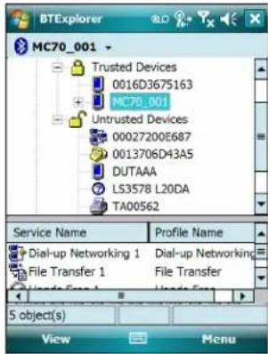
Figure 4-3 Explorer Mode Window
You can also use the "tap and hold" technique to view available options. Scroll bars and view options are similar to those on the Windows desktop. The tree structure lists the following sub-items:
-
Local Device - This device
• Remote Device - Other Bluetooth devices -
Trusted Devices - Bonded (paired) Bluetooth devices
• Untrusted Devices - Discovered devices that are not bonded - Favorites - Selected services that are set as Favorite for quick access.

NOTE Switching between Wizard Mode and Explorer Mode closes all active connections.
Discovering Bluetooth Device(s)
The MC75 can receive information from discovered devices without bonding. However, once bonded, the MC75 and a bonded device exchange information automatically when you turn the Bluetooth radio on. See Bonding with Discovered Device(s) on page 4-20 for more information.
To find Bluetooth devices in the area:
- Ensure that Bluetooth is enabled on both devices.
- Ensure that the Bluetooth device to discover is in discoverable and connectable modes.
- Ensure that the require profile is enabled on the MC75. See Profiles Tab on page 4-32 for more information.
- Ensure that the two devices are within 30 feet (10 meters) of one another.
- Tap the Bluetooth icon and select Show BTExplorer. The BTExplorer window appears.

NOTE If favorite connections have already been created, the Favorites screen displays. If no favorite connections have been created, the New Connection Wizard screen displays.
- Tap Menu > New Connection. The New Connection Wizard appears.
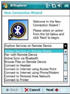
Figure 4-4 BTExplorer Window
- Select Explore Services on Remote Device or another from the drop-down list and tap Next.
The following actions are available in the drop-down list (actions may vary depending upon configurations):
• Explore Services on Remote Device
• Pair with a Remote Device
• Active Sync via Bluetooth
- Browse Files on Remote Device
- Connect to Headset
- Connect to Internet using Access Point
- Connect to Internet using Phone/Modem
- Connect to Personal Area Network
- Connect to Printer
- Send or Exchange Objects
- Associate Serial Port.

NOTE If a device discovery action has not been previously performed, a device discovery is automatically initiated. If a device discovery has previously been performed, the device discovery process is skipped, and the previously found list of devices displays. To start a new device discovery, tap and hold in the window and select Discover Devices from the pop-up menu.
- BTExplorer searches for Bluetooth devices in the area.
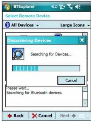
Figure 4-5 Discover Devices Dialog Box
The discovered devices display in the Select Remote Device window.
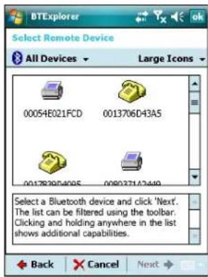
Figure 4-6 Select Remote Device Window
- Select a device from the list and tap Next. The MC75 searches for services on the selected Bluetooth device.
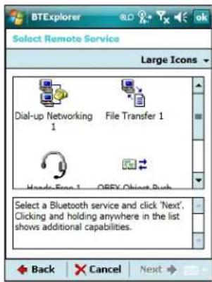
Figure 4-7 Device Services

NOTE If the MC75 discovers a service but the service is not supported, the service icon is grayed-out.
- Select a service from the list and press Next. The Connection Favorite Options window appears.
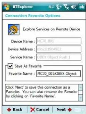
Figure 4-8 Connection Favorite Options Window
- In the Favorite Name text box, enter a name for this service that will appear in the Favorite window.
- Tap Next. The Connection Summary window appears.
- Tap Connect to add the service to the Favorite window and connect to the service.
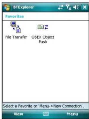
Figure 4-9 Favorites Window
Available Services

NOTE Some devices might not require a PIN. This depends upon the device's authentication.
The MC75 offers the following services:
- File Transfer Services
• Dial-Up Networking Services
• OBEX Object Push Services
• Headset Audio Gateway Services - Hands-Free Audio Gateway Services
- Serial Port Services
• Personal Area Networking Services - IrMC Services.
See the following sections for information on these services.
File Transfer Services

NOTE Shared folders are a security risk.
To transfer files between the MC75 and another Bluetooth enabled device:
- Ensure the MC75 is discoverable and connectable. See Device Info Tab on page 4-23.
- Ensure that OBEX File Transfer profile is enabled on the MC75. See Profiles Tab on page 4-32 for more information.

NOTE If favorite connections have already been created, the Favorites screen displays. If no favorite connections have been created, the New Connection Wizard screen displays.
-
Use the Connection Wizard to search for a Bluetooth device.
-
Select the device and tap Next. The Select Remote Service window appears.
- Tap Next. The Connection Favorite Options window appears.
- Tap Next. The Connection Summary window appears.
- Tap Connect. The remote device's accessible folders appear.
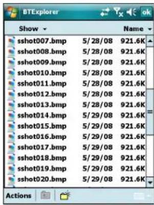
Figure 4-10 File Transfer Window
- Double-tap the file to copy. The Save Remote File window appears.
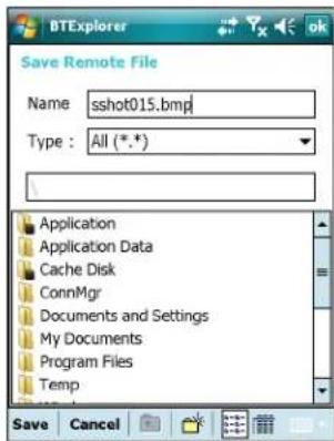
Figure 4-11 Save Remote File Window
-
Tap and hold on the file. A pop-up menu appears.
-
Select the action to perform:
-
New - create a new file or folder on the remote device
- Delete - delete the selected file on the remote device.
• Get File - copy the file from the remote device to the MC75. - Put File - copy a file from the MC75 to the remote device.
Creating a New File or Folder
To create a new folder or file on the remote device:
-
Tap and hold on the screen and select New > Folder or New > File. The Create New Folder or Create New File window appears.
-
Enter the name for the new folder or file.
- Tap OK to create the new folder or file on the remote device.
Deleting a File
To delete a file from the remote device:
- Tap and hold on the file to delete and select Delete.
- In the Delete Remote Device File dialog box tap Yes.
Getting a File
To copy a file from a remote device:
- Double-tap or tap and hold on the file and select Get. The Save Remote File window appears.
- Navigate to the directory to save the file.
- Tap Save. The file is transferred from the remote device to the MC75.
Copying a File
To copy a file to a remote device:
- Tap Action > Put. The Send Local File window appears.
- Navigate to the directory to save the file and select a file.
- Tap Open. The file copies from the MC75 to the remote device.
Connecting to the Internet Using an Access Point
This section explains how to access a Bluetooth-enabled LAN access point (AP) for a network connection. Use Internet Explorer to connect to a server.
- Ensure the MC75 is discoverable and connectable. See Device Info Tab on page 4-23.
- Ensure that the Personal Area Networking profile is enabled on the MC75. See Profiles Tab on page 4-32 for more information.
- Use the Connection Wizard to search for a Bluetooth AP.

NOTE If favorite connections have already been created, the Favorites screen displays. If no favorite connections have been created, the New Connection Wizard screen displays.
- Select the Personal Area Network or Network Access service and select Connect from the pop-up menu. The MC75 connects with the access point.
- Tap Start > Internet Explorer. The Internet Explorer window appears.
- In the address field, enter an internet address and tap the Enter button. The web page loads.

NOTE Network Access profile is not supported.
Dial-Up Networking Services
Dial-up networking allows the user to connect a PC or laptop to the MC75 and use the MC75 as a modem to connect to an office network or ISP.
Before setting up dial-up networking, obtain dial-up information and other necessary settings (username, password and domain name, if required) for the office network or ISP. To create a new Bluetooth connection:
- Ensure the MC75 is discoverable and connectable. See Device Info Tab on page 4-23.
- Ensure that the Dial-Up Networking profile is enabled on the MC75. See Profiles Tab on page 4-32 for more information.
-
Tap Menu > Settings > Services tab.
-
TapAdd button.
-
Select Dial-up networking Service.
-
Tap OK. The Edit Local Services window appears.
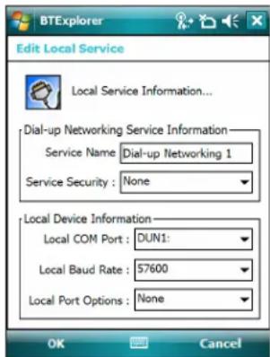
Figure 4-12 Edit Local Service Window
- In the Local COM Port drop-down list, select DUN1 for GSM configurations or WMP9 for CDMA configurations.
- TapOK twice.
- On the PC or laptop, set up Bluetooth according to the manufacturer's instructions.
- On the PC or laptop Bluetooth software, search for the MC75 and select the Dial-up Networking service.
- Using dial-up software on the PC or laptop, connect to the MC75.
- The MC75 phone function dials the ISP number and connects to the ISP.
- To verify, on the PC or laptop, launch Internet Explorer and open a web site.
Object Exchange Push Services
Object Exchange (OBEX) is a set of protocols that allows sharing objects such as Contacts or pictures using Bluetooth.
To exchange contact information with another Bluetooth enabled device:
-
Ensure the MC75 is discoverable and connectable. See Device Info Tab on page 4-23.
-
Ensure that the OBEX Object Push profile is enabled on the MC75. See Profiles Tab on page 4-32 for more information.

NOTE If favorite connections have already been created, the Favorites screen displays. If no favorite connections have been created, the New Connection Wizard screen displays.
- Use the Connection Wizard to search for a Bluetooth device.
- Select the device and tap Next.
- Select the OBEX Object Push service and select Connect. The OBEX Object Push window appears.
- In the Action drop-down list, select one of the following options: Send Contact Information, Swap Contact Information, Fetch Contact Information, or Send a Picture.
Sending a Contact
To send a contact to another device:

NOTE Prior to sending and receiving contacts, a default contact must be set up before attempting to send a contact.
- Tap and hold on OBEX Object Push and select Connect. The OBEX Object Push window appears.
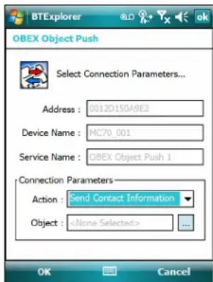
Figure 4-13 OBEX Object Push Window
- In the Action: drop-down list, select Send Contact Information.
- Tap ☐ . The Select Contact Entry window appears.
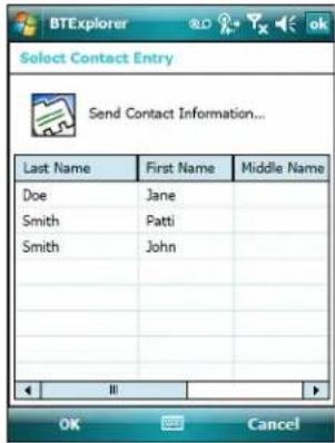
Figure 4-14 Select Contact Entry Window
- Select a contact to send to the other device.
- TapOK.
- Tap OK to send the contact to the other device and display a confirmation dialog box on the other device to accept the contact. A Send Contact dialog appears.
- TapOk.
Swapping Contacts
To swap contacts with another device:

NOTE Prior to swapping contacts, a default contact must be set up before attempting to send a contact.
- Tap and hold on OBEX Object Push and select Connect. The OBEX Object Push window appears.
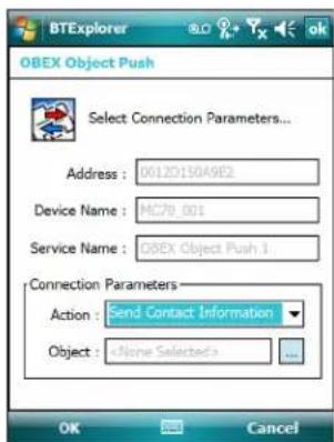
Figure 4-15 OBEX Object Push Window
- In the Action: drop-down list, select Swap Contact Information.
- Tap □ . The Select Contact Entry window appears.
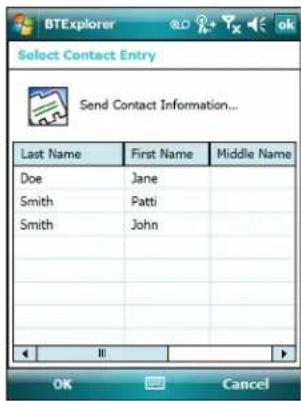
Figure 4-16 Select Contact Entry Window
- Select a contact to send to the other device.
- Tap OK.
- Tap OK to swap contacts with the other device and display a confirmation dialog box on the other device to accept the contact.
- Tap Ok.
Fetching a Contact
To fetch a contact from another device:

NOTE Prior to sending and receiving contacts, a default contact must be set up before attempting to send a contact.
- Tap and hold on OBEX Object Push and select Connect. The OBEX Object Push window appears.
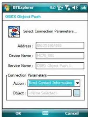
Figure 4-17 OBEX Object Push Window
- In the Action: drop-down list, select Fetch Contact information.
- Tap OK. The contact on the other device is copied.
Sending a Picture
To send a picture to another device:
- Tap and hold on OBEX Object Push and select Connect. The OBEX Object Push window appears.
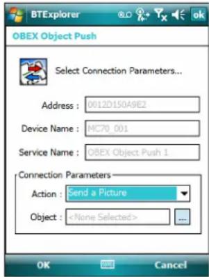
Figure 4-18 OBEX Object Push Window
- In the Action: drop-down list, select Send A Picture.
- Tap ☐ . The Send Local Picture window appears.
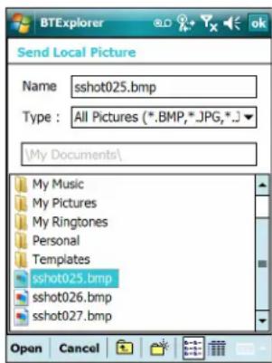
Figure 4-19 Send Local Picture Window
- Navigate to the picture to send to the other device.
- TapOpen.
- Tap OK to send the picture to the other device and display a confirmation dialog box on the other device to accept the picture. A Send Picture dialog appears.
- TapOk.
Headset Services
To connect to a Bluetooth headset:

NOTE Newer Bluetooth headsets are device dependant and remember the last device they connected to. If problems occur while connecting to the headset, place the headset in discovery mode. Refer to the headset user manual for more information.
-
Ensure the MC75 is discoverable and connectable. See Device Info Tab on page 4-23.
-
Ensure that the Headset profile is enabled on the MC75. See Profiles Tab on page 4-32 for more information.
- Use the Connection Wizard to search for a Bluetooth headset.
- Select the device and tap Next.
- Select the Headset service name and select Connect. The MC75 connects to the headset. Refer to the headset user manual for instructions on communicating with a Bluetooth device.

NOTE When using a Bluetooth headset with Headset Services, you cannot accept or end a call from the headset. You must accept or end a call on the MC75.
- Press the communication button on the headset. This routes both system and WAN call audio to the headset.
- When a call is received on the MC75, tap the Accept button to answer the call.
- Press the communication button on the headset to route the audio back to the MC75.

NOTE If a wired headset is connected to the MC75, the Bluetooth headset connection is disconnected.
Hands-free Services
To connect to a Bluetooth headset:

NOTE Newer Bluetooth headsets are device dependant and remember the last device they connected to. If problems occur while connecting to the headset, place the headset in discovery mode. Refer to the headset user manual for more information.
Only WAN audio is routed to the headset. System audio is still emitted through the MC75 speaker.
You can accept calls and re-dial using the Hands-free profile.
Hands-free profile does not support 3-way calling.
- Ensure the MC75 is discoverable and connectable. See Device Info Tab on page 4-23.
- Ensure that the Hands Free profile is enabled on the MC75. See Profiles Tab on page 4-32 for more information.
- Use the Connection Wizard to search for a Bluetooth hands-free headset.
- Select the hand-free device and tap Next.
- Select the Hands-free service name and select Connect. The MC75 connects to the headset. Refer to the headset user manual for instructions on communicating with a Bluetooth device.
- During an active connection, the MC75 cannot go into suspend mode when the Power Button is pressed. A message appears notifying the user.
Once the WAN call is disconnected (with Hands-free profile) the Power button is enabled.
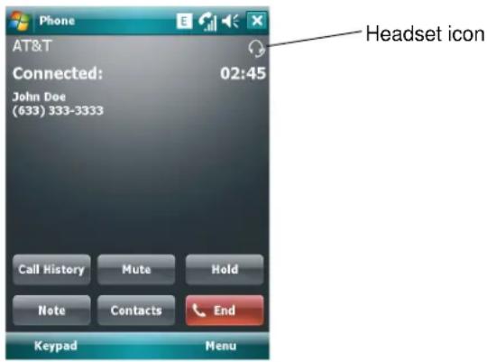
Figure 4-20 WWAN Bluetooth Audio Notification Dialog Box
Serial Port Services
Use the wireless Bluetooth serial port connection as you would a physical serial cable connection. Configure the application that will use the connection to the correct serial port.
To establish a serial port connection:
- Ensure the MC75 is discoverable and connectable. See Device Info Tab on page 4-23.
- Use the Connection Wizard to search for a Bluetooth serial device.
- Select the device and tap Next. The Connection Favorite Options window appears.
- In the Local COM Port: drop-down list select a COM port.
- TapFinish.
ActiveSync Using Serial Port Services

NOTE By default, COM ports COM5, COM9, COM11, COM21, COM22 and COM23 are Bluetooth virtual ports. If an application opens one of these ports, the Bluetooth driver activates and guides you through a Bluetooth connection.
Use the wireless Bluetooth serial port connection for ActiveSync just as you would a physical serial cable connection. You must configure the application that will use the connection to the correct serial port.
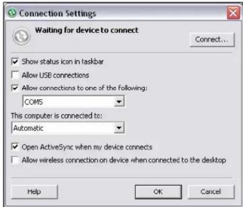
Figure 4-21 ActiveSync Connection Settings Window on PC
To establish an ActiveSync connection:
- Ensure the MC75 is discoverable and connectable. See Device Info Tab on page 4-23.
- Ensure that the Sync profile is enabled on the MC75. See Profiles Tab on page 4-32 for more information.
- Use the Connection Wizard to search for a Bluetooth device, such as a PC. In the drop-down list select ActiveSync via Bluetooth.
- Select the device and tap Next. The Connection Favorite Options window appears.
- Tap Connect. The Remote Service Connection window appears.
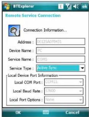
Figure 4-22 Remote Service Connection Window
- In the Service Type drop-down list, select Active Sync.
- Tap OK. The MC75 connects the PC and an ActiveSync session begins.
- Tap Finish. The Connection Favorite Options window appears.
- To end the session, tap the ActiveSync icon in the Favorite window and select Disconnect from the pop-up window.
Personal Area Network Services

NOTE This profile supports Ad-hoc and PAN User. Network Access Profile is not supported.
Connect two or more Bluetooth devices to share files, collaborate, or play multi-player games. To establish a Personal Area Network connection:
- Ensure the MC75 is discoverable and connectable. See Device Info Tab on page 4-23.
- Ensure that the Personal Area Networking profile is enabled on the MC75. See Profiles Tab on page 4-32 for more information.
- Use the Connection Wizard to search for a Bluetooth device.
- Select the device and tap Next. The Connection Favorite Options window appears.
- Tap Next. The Connection Summary window appears.
- Tap Connect. The MC75 connects to the Bluetooth device.
IrMC Synchronization Services
IrMC Synchronization is used to synchronize PIM contacts between a remote device and the MC75. To establish an IrMC synchronization:
- Ensure the MC75 is discoverable and connectable. See Device Info Tab on page 4-23.
- Ensure that the Sync profile is enabled on the MC75. See Profiles Tab on page 4-32 for more information.
- Tap Menu > Settings > Services tab.
- TapAdd button.
- Select IrMC Synchronization.
- Tap OK. The Edit Local Services window appears.
- TapOK twice.
- Use the Connection Wizard to search for a Bluetooth device, such as a Car Kit.
- Select the device and tap Next. The Connection Favorite Options window appears.
- Tap and hold IrMA Synchronization and select Connect in the pop-up menu.

NOTE To automatically transfer contact with a Car Kit, ensure that the IrMC Synchronization service is enabled on the MC75.
Bonding with Discovered Device(s)
A bond is a relationship created between the MC75 and another Bluetooth device in order to exchange information in a secure manner. Creating a bond involves entering the same PIN on the two devices. After creating a bond and turning on the Bluetooth radios, the devices recognize the bond and can exchange information without re-entering a PIN.
To bond with a discovered Bluetooth device:

NOTE If favorite connections have already been created, the Favorites screen displays. If no favorite connections have been created, the New Connection Wizard screen displays.
-
Tap the Bluetooth icon and select Show BTExplorer. The BTExplorer window appears.
-
Tap Menu > New Connection. The New Connection Wizard window appears.
-
In the drop-down list, select Pair with Remote Device.
-
Tap Next. The Select Remote Device window appears.

NOTE Devices discovered previously are listed to save time. To start a new device discovery, tap and hold on the list area and select Discover Devices from the pop-up menu.
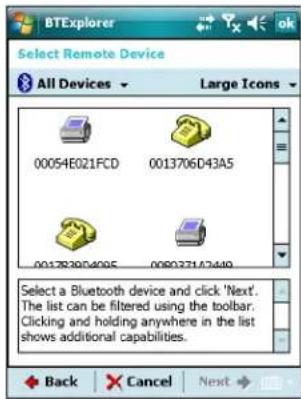
Figure 4-23 Select Remote Device Window
- Select a device from the list and tap Next. The PIN Code Request window appears.
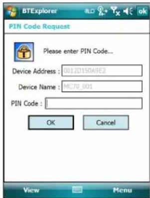
Figure 4-24 Connection Favorite Options Window
-
In the PIN Code field, enter the PIN code.
-
Tap OK. The Pairing Status window displays.
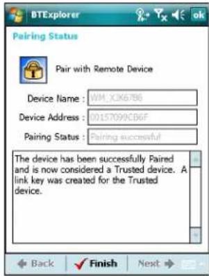
Figure 4-25 Pairing Status Window
- Tap Finish. The devices are successfully paired. The device name moves to the Trusted Devices window.
Deleting a Bonded Device
To delete a device no longer needed:
- Tap the Bluetooth icon and select Show BTExplorer. The BTExplorer window appears.
- Tap Menu > Trusted Devices. The Trusted Devices window appears.
- Tap and hold on the device select Delete Link Key in the pop-up menu.
- A confirmation dialog appears. Tap Yes.
Accepting a Bond
When a remote device wants to bond with the MC75, enter a PIN when requested to grant permission.
- Ensure that the MC75 is set to discoverable and connectable. See Bluetooth Settings on page 4-23. When prompted to bond with the remote device the PIN Code Request window appears.
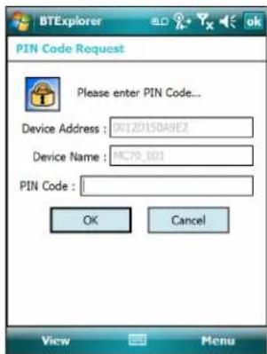
Figure 4-26 PIN Code Request Window
- In the PIN Code: text box, enter the same PIN entered on the device requesting the bond. The PIN must be between 1 and 16 characters.
-
In the Device Name: text box, edit the name of the device requesting the bond, if desired.
-
Tap OK to create the bond. The MC75 can now exchange information with the other device.
Bluetooth Settings
Use the BTExplorer Settings window to configure the operation of the BTExplorer application. Tap Menu > Settings. The BTExplorer Settings window appears.
Device Info Tab
Use the Device Info tab to configure the MC75's Bluetooth connection modes.
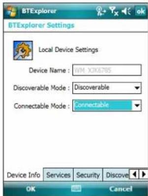
Figure 4-27 BTExplorer Settings - Device Info Tab
Device Name Displays the name of the MC75.
Discoverable Mode Select whether or not the MC75 is discoverable by other Bluetooth devices.
Connectable Mode Select whether or not the MC75 is connectable by other Bluetooth devices.
Services Tab
Use the Services tab to add or delete Bluetooth services.
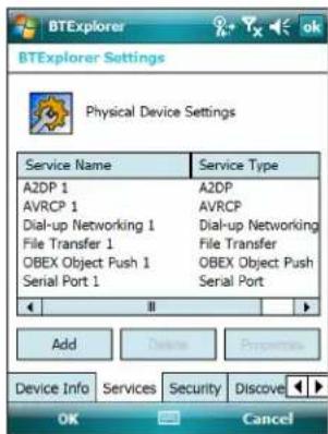
Figure 4-28 BTExplorer Settings - Services Tab
To add a service:
- Tap Add. The Add Local Service window displays.
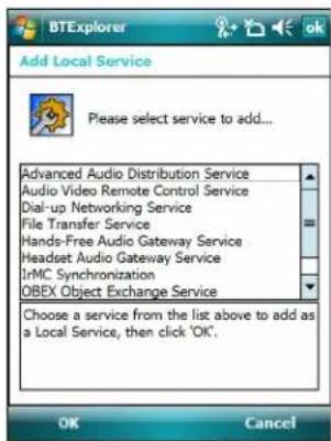
Figure 4-29 Add Local Service Window
- In the list, select a service to add.
- Tap OK. The Edit Local Service window displays for the selected service.
- Select the appropriate information and then tap OK. See the following sections for information on the available services.
Dial-Up Networking Service
Dial-up Networking allows other Bluetooth devices to access a dial-up modem.
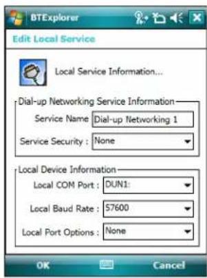
Figure 4-30 Add Local Service Window
Table 4-1
| Item Description | |
| Service Name Displays | the name of the service. |
| Service Security | Select the type of security from the drop-down list. Options are None, Authenticate, or Authenticate/Encrypt. |
Table 4-1
| Item Description | |
| Local COM Port Select | the COM port. |
| Local Baud Rate Select | the communication baud rate. |
| Local Port Options Select | the port option. |
File Transfer Service
File transfer allows other Bluetooth devices to browse files.
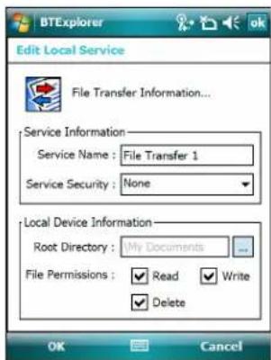
Figure 4-31 BTExplorer Settings - File Transfer Information
Table 4-2 File Transfer Information Data
| Item Description | |
| Service Name Displays the name of the service. | |
| Service Security | Select the type of security from the drop-down list. Options are None, Authenticate, or Authenticate/Encrypt. |
| Root Directory Select the directory that other Bluetooth devices can access. | |
| File Permissions | Select the file permissions for the selected directory. Check the appropriate box to grant read access, write access, and delete access. |
Hands-Free Audio Gateway Service
Hands-Free Service Audio Gateway allows connection to hands-free devices.
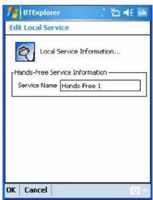
Figure 4-32 BTExplorer Settings - Hands-Free Audio Gateway
Table 4-3 Hands-Free Audio Gateway Data
| item Description |
| Service Name Lists the name of the audio service. |
Headset Audio Gateway Service
Headset Service Audio Gateway allows connection to headset devices.
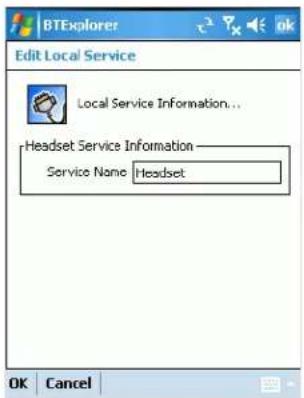
Figure 4-33 BTExplorer Settings - Headset Audio Gateway
Table 4-4 Headset Audio Gateway Data
| Item Description |
| Service Name Lists the name of the audio service. |
IrMC Synchronization Service
The IrMC Synchronization service used to synchronize PIM contacts between a remote device and the MC75.
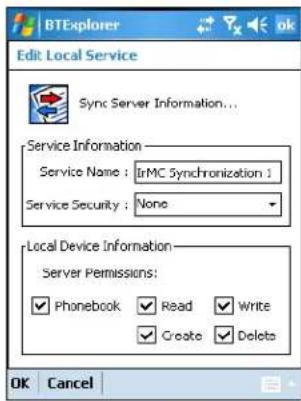
Figure 4-34 BTExplorer Settings - IrMC Synchronization
Table 4-5 IrMC Synchronization Data
| Item Description | |
| Service Name Displays | the name of the service. |
| Service Security | Select the type of security from the drop-down list. Options are None, Authenticate, or Authenticate/Encrypt. |
| Phonebook | Select the Phonebook checkbox to allow synchronization with the MC75's contacts. |
| Select Read, Write, Create and/or Delete to allow phonebook permissions. | |
OBEX Object Push Service
OBEX Object Push allows other Bluetooth devices to push contacts, business cards, pictures, appointments, and tasks to the MC75.
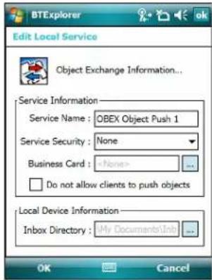
Figure 4-35 BTExplorer Settings - OBEX Exchange Information
Table 4-6 OBEX Exchange Information Data
| Item Description | |
| Service Name Displays the name of the service. | |
| Service Security | Select the type of security from the drop-down list. Options are None, Authenticate, or Authenticate/Encrypt. |
| Do not allow clients to push objects Disables clients from pushing objects to the MC75. | |
| Inbox Directory Select a directory where another Bluetooth device can store files. | |
Personal Area Networking Service
Personal Area Networking hosts a Personal Area Network which allows communication with other Bluetooth devices.
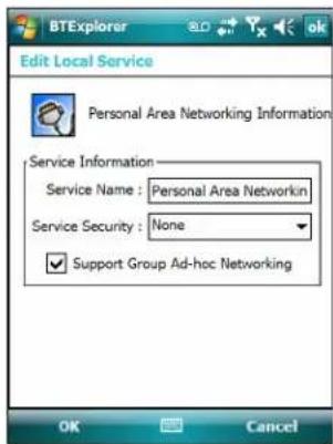
Figure 4-36 BTExplorer Settings - Personal Area Networking
Table 4-7 Personal Area Networking Data
| Item Description | |
| Service Name Displays the name | of the service. |
| Service Security | Select the type of security from the drop-down list. Options are None, Authenticate, or Authenticate/Encrypt. |
| Support Group Ad-Hoc Networking | Select to enable Ad-Hoc networking. |
Serial Port Service
Serial port allows other Bluetooth devices to access COM ports.
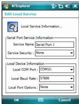
Figure 4-37 BTExplorer Settings - Serial Port Services
Table 4-8 Serial Port Services Data
| Item Description | |
| Service Name Displays | the name of the service. |
| Service Security | Select the type of security from the drop-down list. Options are None, Authenticate, or Authenticate/Encrypt. |
| Local COM Port Select | the COM port. |
| Local Baud Rate Select | the communication baud rate. |
| Local Port Options Select | the port option. |
Security Tab
Security settings allows you to set global security policies for Bluetooth. Note that these settings are only active on local Services that are set to Authenticate or Authenticate/Encryption. You can set authentication on local Services under the Services tab.
To adjust the security settings for an individual service, select the Services tab first, then select the individual service, then Properties.
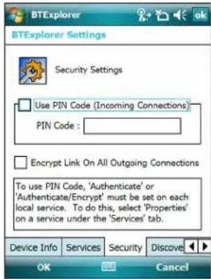
Figure 4-38 BTExplorer Settings - Security Tab

NOTE To use PIN Code, select Authenticate or Authenticate/Encrypt from the Service Security drop-down list on each local service.
Table 4-9 Security Tab Data
| Item Description | |
| Use PIN Code (Incoming Connection) | Select for automatic use of the PIN code entered in the PIN Code text box. It is recommended not to use this automatic PIN code feature. See Security on page 4-2 for more information. |
| PIN Code Enter the PIN code. | |
| Encrypt Link On All Outgoing Connections | Select to enable or disable encryption on all outgoing connections to other Bluetooth devices. |
Discovery Tab
Use the Discovery tab to set and modify discovered devices.
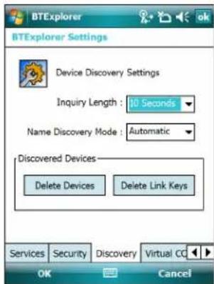
Figure 4-39 BTExplorer Settings - Discovery Tab
Table 4-10 Discovery Tab Data
| Item Description | |
| Inquiry Length Sets the amount of time the MC75 takes to discover Bluetooth devices in the area. | |
| Name Discovery Mode | Select either Automatic or Manual to automatically attempt to discover a Bluetooth device's name after finding the device. |
| Discovered Devices - Delete Devices | Deletes all discovered devices and link keys from memory. |
| Discovered Devices - Delete Linked Keys | Removes all pairing from remote Bluetooth devices, and makes them all un-trusted. |
Virtual COM Port Tab
Virtual COM Port defines which COM ports BTExplorer attempts to use for virtual COM ports. Check the appropriate checkbox to use the port as a virtual COM port. When finished, choose Apply to enforce changes, or Revert to restore the original settings.
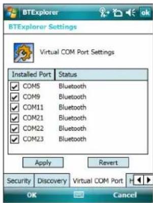
Figure 4-40 BTExplorer Settings - Virtual COM Port Tab
Table 4-11 Virtual COM Port Tab Data
| Item Description | |
| COM5:Bluetooth Enable or disable | COM Port 5. |
| COM9:Bluetooth Enable or disable | COM Port 9. |
| COM11:Bluetooth Enable or disable | COM Port 11. |
| COM21:Bluetooth Enable or disable | COM Port 21. |
| COM22:Bluetooth Enable or disable | COM Port 22. |
| COM23:Bluetooth Enable or disable | COM Port 23. |
HID Tab
Use the HID tab to select The Human Interface Device Profile programming interface defines the protocols and procedures to be used to implement HID capabilities.
Provides support for devices such as mice, joysticks, keyboards.
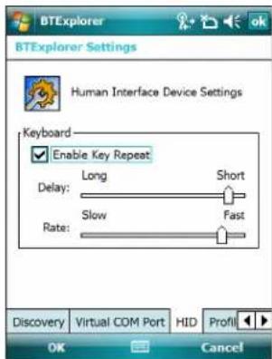
Figure 4-41 BTExplorer Settings - HID Tab
Table 4-12 HID Tab Data
| Item Description | |
| Enable Key Repeat Enables key repeat functionality. | |
| Delay | To increase key repeat delay, drag the Delay slider to the right. To decrease key repeat delay, drag the Delay slider to the left. |
| Rate | To increase key repeat speed, drag the Rate slider to the left. To decrease key repeat speed, drag the Rate slider to the right. |
Profiles Tab
Use the Profile tab to load or remove Bluetooth services profiles. If a profile is not used, it can be removed to save memory.
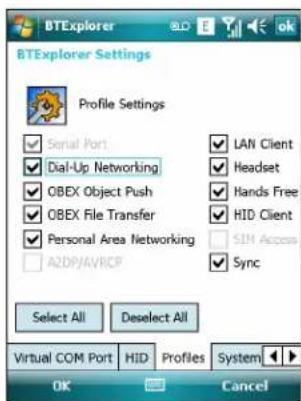
Figure 4-42 BTExplorer Settings - Profile Tab
- Tap a check box next to the profile to load (activate).
The Serial Port profile is always active and cannot be removed.
- Tap Select All to select all profiles or tap Deselect All to deselect all profiles.
- Tap Apply to activate the profiles and then Close to exit the application.
System Parameters Tab
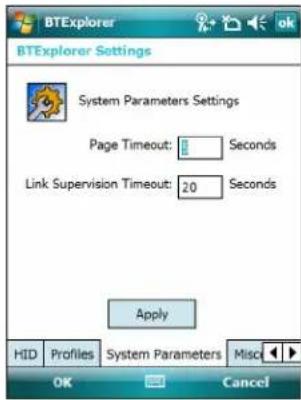
Figure 4-43 BTExplorer Settings - System Parameters Tab
Table 4-13 System Parameters Tab Data
| item Description | |
| Page Timeout Sets the amount of time the MC75 searches for a device before moving on the next device. | |
| Link Supervision Timeout | Sets the amount of time that the MC75 will wait for a device to come back into range after it has gone out of range. If the device does not come back into range by the set time, the MC75 drops the connection. |
Miscellaneous Tab
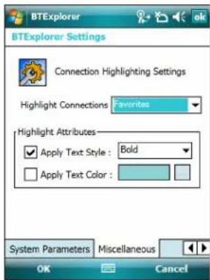
Figure 4-44 BTExplorer Settings - Miscellaneous Tab
Table 4-14 Miscellaneous tab Data
| Item Description | |
| Highlight Connections | Select the connection type to highlight when connected. In the Wizard Mode, the only options are Favorites or None. In the Explorer Mode the options are None, Tree View Only, List View Only, or Tree and List View. |
| Apply Text Style Select the text style to apply to the connection text. | |
| Apply Text Color Select the text color to apply to the connection text. | |
Chapter 5 Using the Phone
Introduction
Use the MC75 to make phone calls, set up speed dials, keep track of calls, and send text messages. Your wireless service provider may also provide other services such as voice mail, call forwarding, and caller ID.
Also use the integrated phone to connect to an ISP or work network in order to browse the Web and read e-mail. Connect to the Internet or work network over High-Speed Downlink Packet Access (HSDPA) (MC7506 and MC7596) or Evolution Data-Optimized (EvDO) (MC7508 and MC7598) using Cellular Line, or using the modem specified by the mobile operator. For more information, or to customize the MC75 phone by changing phone settings, see the MC75 Integrator Guide.
Accessing the Phone Keypad

NOTE Keypads vary depending on services and the state of the phone. For example, place calls on hold and use Swap to switch active calls on hold. (See Conference Calling on an MC7506/96 on page 5-20.)
Access the keypad regardless of the program in use. Applications on the MC75 can be in use during a call.
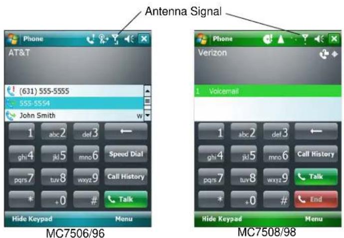
Figure 5-1 Phone Keypads
To access the phone keypad tap Start > Phone or press the green phone key on the MC75's keypad.
To receive calls when the MC75 is suspended, leave the phone radio turned on and ensure the MC75 is set to wake with any key.
Turning the Phone On and Off
Windows Mobile 6 devices include Wireless Manager, which provides a simple method of enabling and disabling the phone.
To open Wireless Manager, tap the Connectivity icon.
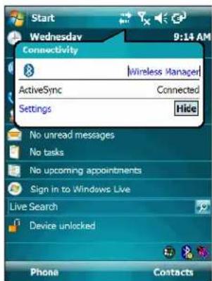
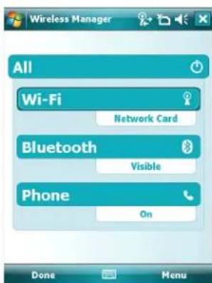
Figure 5-2 Opening Wireless Manager
Select Wireless Manager. The Wireless Manager window appears.
To toggle on or off the phone, tap blue Phone bar.
To configure settings for a connection, tap Menu > Phone Settings.

NOTE To receive calls when your device is suspended, leave the phone turned on.
Audio Modes
The MC75 offers three audio modes for use during phone calls:
- Handset Mode: Switches audio to the speaker at the top front of the MC75, so you can use the MC75 as a handset. This is the default mode.
- Speaker Mode: Use the MC75 as if on speaker phone. Tap the Speaker On button to activate this mode. Tap the Speaker Off button to switch back to handset mode.
- Headset Mode: Connect a wired or Bluetooth headset to automatically switch audio to the headset.
The MC75 defaults to handset mode. When a wired headset is plugged into the MC75 audio connector or a Bluetooth headset is configured for use with the MC75, the earpiece and speakerphone are muted and audio is heard through the headset.
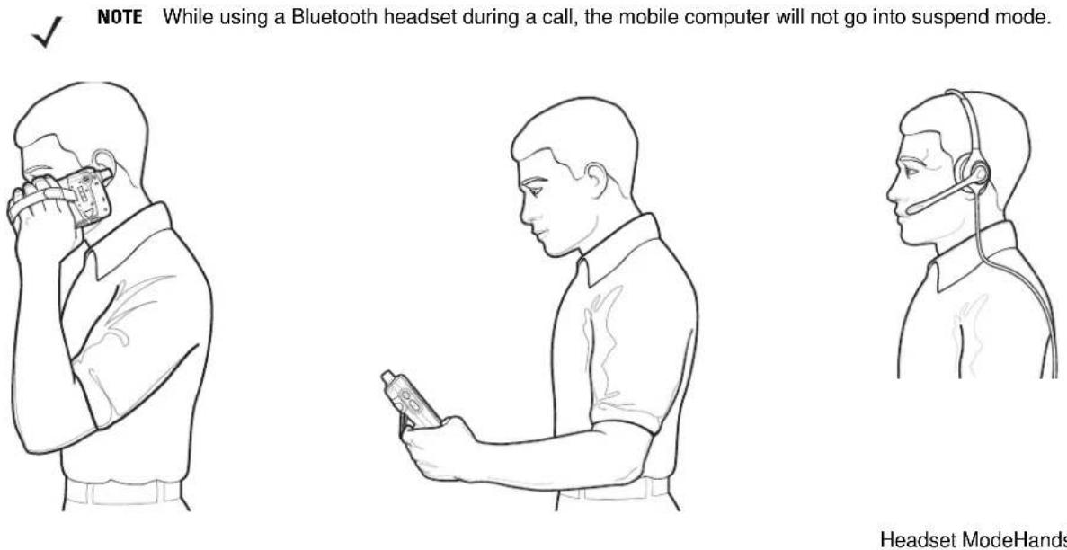
Headset ModeHandset Mode
Figure 5-3 Audio Modes
Using a Wired Headset
You can use a stereo headset for audio communication when using an audio-enabled application. To use a headset, plug the headset jack into the audio connector on the side of the MC75. Set the MC75's volume appropriately before putting the headset on. Plugging a headset into the jack mutes the speaker.
For the best audio performance, Motorola recommends a 2.5mm jack headset, see Accessories on page 1-3.
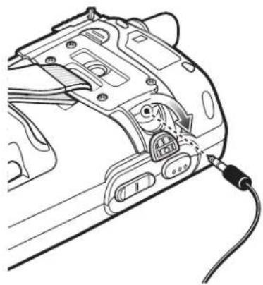
natural_image
Line drawing of a camera body panel with attached cable and connector (no text or symbols)Figure 5-4 Using a Headset
Using a Bluetooth Headset
You can use a Bluetooth headset for audio communication when using an audio-enabled application. See Chapter 4, Using Bluetooth for information on connecting a Bluetooth headset to the MC75. Set the MC75's volume appropriately before putting the headset on. When a Bluetooth headset is connected the speakerphone is muted.
It is recommended for phone conversations to use the Bluetooth Hands-free profile instead of the Headset profile. See Chapter 4, Using Bluetooth for more information.

NOTE When using a Bluetooth headset during a call, the MC75 power button is disabled and the MC75 will not go into suspend mode. Once the call is completed, the power button functionality is enabled.
The following dialog box displays when a Bluetooth headset connection is established.
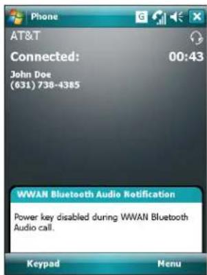
Figure 5-5 WWAN Bluetooth Audio Notification Dialog Box
Adjusting Audio Volume
Use the Volume Control Slider or the keypad keys to adjust the volume of the ringer when not in a call and the audio volume when in a call.
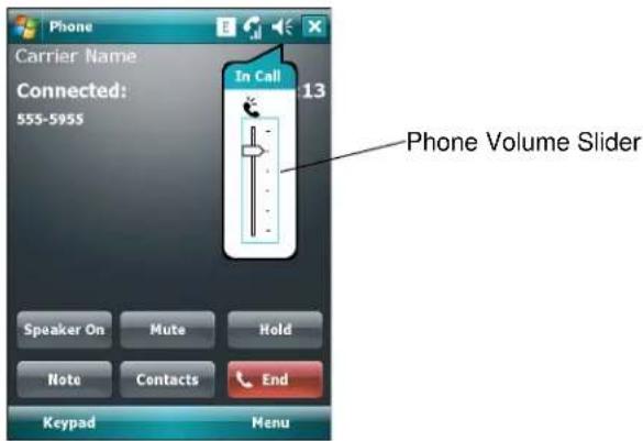
Figure 5-6 Phone Volume Slider
To adjust the volume tap the Speaker icon in the Title bar. Move the slider up or down to adjust the volume.

NOTE Adjust the conversation phone volume during a call. Adjusting the volume while not in a call affects the ring and notification sound levels.
Making a Call

NOTE You can make emergency calls even when the MC75 is locked or when a SIM card is not installed. See Making an Emergency Call on page 5-7 for more information.
With the MC75, you can make a call from the phone, contacts, speed dial and call history.
Using the Phone
To make a call using the phone keypad:
- Tap Start > Phone or press the green phone key on the MC75's keypad.
- From the Phone keypad, tap the number to call.
- Tap Talk.
- Tap End to stop dialing or end the call.

NOTE Alternatively, use the green and red phone keys on the MC75 keypad to dial (green) and end (red) calls.
If you tap a wrong number, tap Delete key to erase each subsequent digit of a number. To erase the entire number, tap and hold the Delete key.
Using Contacts
Use Contacts to make a call without looking up or entering the phone number.
To make a call from Contacts:
- Tap Start > Contacts.
- From the contact list, tap and hold the contact name.
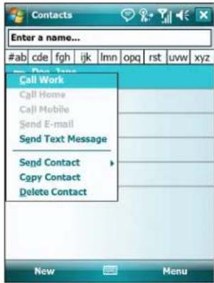
Figure 5-7 Contacts Menu
- Tap Call Work, Call Home or Call Mobile.

NOTE To make a call from an open contact, tap the number to call. See On-Device Help for more information about Contacts.
Using Call History
To make a call using Call History:
- Tap Start > Phone or press the green phone key on the MC75's keypad.
- From the Phone keypad, tap Call History.
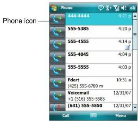
Figure 5-8 Call History
- Tap the phone icon next to the number to begin dialing and return to the phone keypad.
- Tap End or press the red phone key on the MC75 keypad to stop dialing or end the call.
Making a Speed Dial Call
Use Speed Dial to call someone saved in the speed dial directory.
To make a speed dial call:
-
Tap Start > Phone or press the green phone key on the MC75's keypad.
-
From the Phone keypad, tap and hold the speed dial location number assigned to a contact. (To dial a one-digit speed dial location number, tap and hold the speed dial number. To dial a two-digit speed dial location number, tap the first digit and then tap and hold the second digit.)
or
From the Phone keypad, tap Speed Dial and tap the speed dial location number of the desired contact in the list.
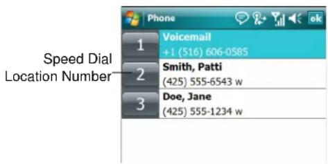
Figure 5-9 Speed Dial Contact List
- To stop dialing or end the call, tap End or press the red phone key on the MC75 keypad.
Making an Emergency Call
Your service provider programs one or more emergency phone numbers, such as 911 or 999, that you can call under any circumstances, even when your phone is locked or the SIM card is not inserted (on MC7506/96). Your service provider can program additional emergency numbers into your SIM card. However, your SIM card must be inserted in your phone in order to use the numbers stored on it. See your service provider for additional information. See Installing the SIM Card on page 1-4 for SIM card installation procedures.
When the alpha-numeric keypad phone is locked, press the Orange key twice to set the keypad to numeric mode and then enter the emergency number.

NOTE Emergency numbers vary by country. Your phone's pre-programmed emergency number(s) may not work in all locations, and sometimes an emergency call cannot be placed due to network, environmental, or interference issues.
Answering a Call
A dialog box appears on the MC75 when it receives an incoming call. If the phone is set to ring, a ring tone sounds. Answer or ignore the incoming call.
To answer an incoming call tap Answer on the Phone - Incoming dialog or press the green phone key on the MC75 keypad.
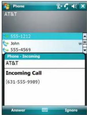
Figure 5-10 Incoming Call
To ignore the incoming call tap Ignore. This may send the caller to voice mail, depending on the service provider. Otherwise, this presents busy signal to the calling party.
To end the call tap End or press the red phone key on the MC75 keypad.
Incoming Call Features
- If you receive a call while in a call, tap Wait to place the call in call waiting.
- You can use other programs on the MC75 during a call. To switch back to Phone, tap Talk or tap Start > Phone. Tap End to end the call.
- If a caller isn't in your contact list, create a contact during the call or from Call History by tapping Menu > Save to Contacts.
- To terminate a call when a second call comes in and answer the waiting call, tap End on the Phone keypad to disconnect the active call, then tap Answer or press the Send key to answer the waiting call.
- To hold the current call and answer a waiting call, tap Answer or press the Send key to place the current call on hold and answer the incoming call.
• To put a call on hold to call another number or answer an incoming call, tap Hold on an MC7506/96 or Talk on an MC7508/98. To move from one call to another, tap Swap on an MC7506/96 or Talk on an MC7508/98
Smart Dialing
Smart Dialing makes it easy to dial a phone number. When you start entering numbers or characters, Smart Dialing automatically searches and sorts the contact entries on the SIM card, in Contacts, and the phone numbers in Call History (including incoming, outgoing, and missed calls). You can then select the desired number or contact from the filtered list to dial.
Open the Phone screen, then tap the keys on the Phone keypad that correspond to the phone number or contact to call. The contact panel lists contacts that match the sequence that you entered.
Smart Dialing starts looking for numbers or contacts that match the sequence entered.
To find a phone number:
- Enter the first one or two digits to find a phone number in Call History.
- Enter the first three digits or more to find a phone number from the saved Contacts and SIM card.
To find a contact name:
- Enter the first letter of a contact's first name or last name. Smart Dialing searches for the letter starting from the first character of a contact name as well as from the character that appears after a space, dash, or underscore in a contact name. For example, if you tap number "2" which is associated with [a, b, c] on the Phone keypad, contact names such as the following will be considered matches: "Smith, Bernard", "Adams, John", "Carlson, Eileen", "Dillon, Albert", "Childs, Larry", "Cooper, Robert" and "Parks, Celine".
- If the matching list is long narrow down the search further by entering another letter. Using the same example above, tap "3" which is associated with (d, e, f), the matching list is narrowed down to the following names: "Smith, Bernard", "Adams, John", and "Parks, Celine".
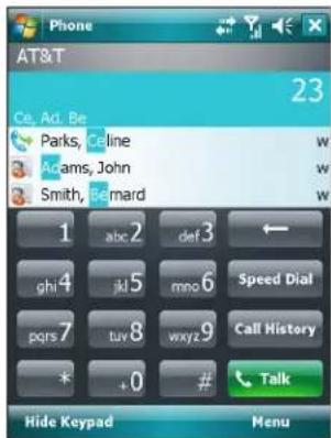
Figure 5-11 Finding a Contact
To make a call or send a text message using Smart Dialing:
- Begin entering the first few numbers or characters.
- In the Smart Dialing panel, use the up and down arrows on the keypad to navigate to the desired contact or phone number.
- When the correct contact is selected, press TALK to make a voice call.
- To send a text message to the selected contact, tap Menu > Send Text Message.
- To call a different phone number associated with the selected contact, tap the contact name and select the phone number to call.
Muting a Call
During a call, you can mute the microphone so you can hear the person on the line but he or she cannot hear conversation from the microphone. This is useful when there is conversation or background noise on your end.
To mute or unmute a call:
- Tap Start > Phone or press the green phone key on the MC75's keypad.
- Make a call.
- Tap Mute on the display to mute the audio. The Mute icon appears.
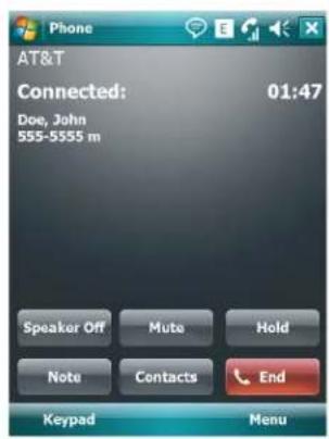
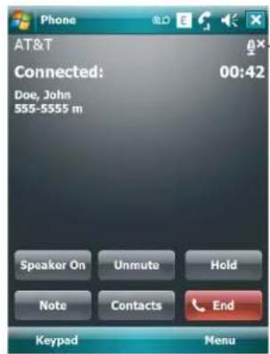
Mute Icon
Figure 5-12 Mute Button and Icon
Taking Notes
To create a note during a call, tap Note on the display, then enter the note. For more information about creating notes see the Windows On-Device Help.
To access a note created during a call:
- Tap Start > Phone or press the green phone key on the MC75's keypad.
- From the Phone keypad, tap Call History.
- Tap and hold the number or the Note icon for the phone call entry containing the note.
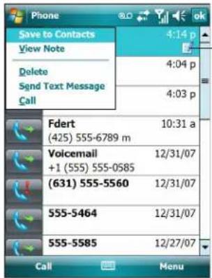
-Note icon
Figure 5-13 Call History - Notes Menu
- Tap View Note.
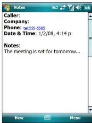
Figure 5-14 Call History - Notes
- Tapok to exit.

NOTE Also access notes directly from the Notes application by tapping Start > Notes.
Using Speed Dial
Create speed dial numbers to dial frequently called numbers with a single tap. Before creating a speed dial entry, ensure the phone number exists in Contacts.
Adding a Speed Dial Entry
To add a speed dial entry from the phone keypad:
- Ensure the contact and phone number are in the Contacts list.
- Tap Start > Phone or press the green phone key on the MC75's keypad.
- Tap Menu > Speed Dial > Menu > New.
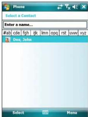
Figure 5-15 Contacts
- Tap the desired contact name and number in the list.
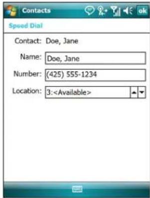
Figure 5-16 Speed Dial Contact Location
- In the Location field, tap the up/down arrows to select an available location to assign as the new speed dial entry. The first speed dial location is reserved for voice mail.
- Tap ok to add the contact to the speed dial list.
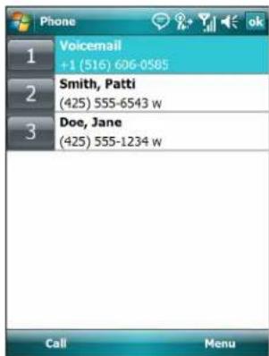
Figure 5-17 Speed Dial Contact List
- Tap ok to exit the Speed Dial Contact List.
To add a speed dial entry from the Contacts window:
- Tap Start > Contacts.
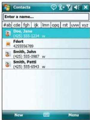
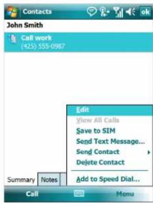
Figure 5-18 Contacts
- Tap a contact name.
- Tap Menu > Add to Speed Dial.
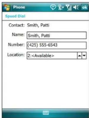
Figure 5-19 Speed Dial Contact Location
- Tap the up/down arrows to select an available location to assign as the new speed dial entry. The first speed dial location is reserved for voice mail.
- Tapok.
Editing a Speed Dial Entry
- Tap Start > Phone or press the green phone key on the MC75's keypad.
- Tap Menu > Speed Dial.
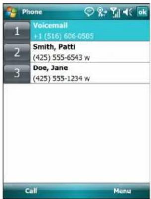
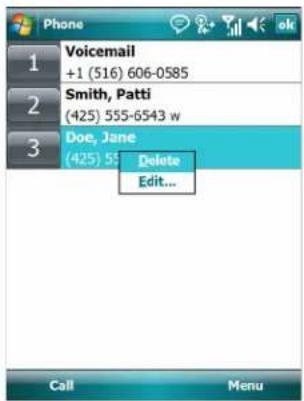
Figure 5-20 Speed Dial Contact List
- Tap and hold the contact name.
- TapEdit...
- Change the name, phone number, or location information.
- Tapok.

NOTE Editing names and phone numbers in Speed Dial does not alter contact information in Contacts (Start > Contacts).
Deleting a Speed Dial Entry
- Tap Start > Phone or press the green phone key on the MC75's keypad.
- Tap Menu > Speed Dial.
- Tap and hold the contact name.
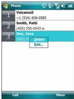
Figure 5-21 Speed Dial Delete Menu
- TapDelete.
- Tap Yes to confirm permanently deleting the speed dial entry.

NOTE Deleting names and phone numbers in Speed Dial does not delete the contact information in Contacts (Start > Contacts).
Using Call History
Use Call History to call someone who was recently called, or recently called in. Call History provides the time and duration of all incoming, outgoing, and missed calls. It also provides a summary of total calls and easy access to notes taken during a call. Table 4-1 lists the call history icons that appear in the Call History window.
Table 5-1 Call History Icons
| Icon Description | |
 | This icon appears next to the contact information for all outgoing calls. |
 | This icon appears next to the contact information for all incoming calls. |
 | This icon appears next to the contact information for all missed calls. |
Managing Call History
Change views, reset the call timer, and delete calls to manage the calls stored in Call History.
Changing the Call History View
- Tap Start > Phone or press the green phone key on the MC75's keypad to display the Phone keypad.
- From the Phone keypad, tap Call History.
- Tap Menu > Filter to show the menu.
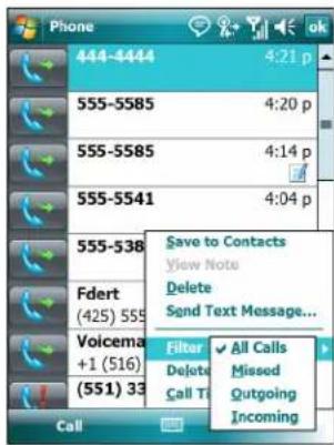
Figure 5-22 Call History - All Calls/Show Menu
- Select a view type from the menu to display only missed calls, outgoing calls, incoming calls, or calls listed alphabetically by caller name.
- Tap ok to exit the Call History window.
Resetting the Recent Calls Counter
- Tap Start > Phone or press the green phone key on the MC75's keypad to display the Phone keypad.
- From the Phone keypad, tap Call History.
3. Tap Menu.
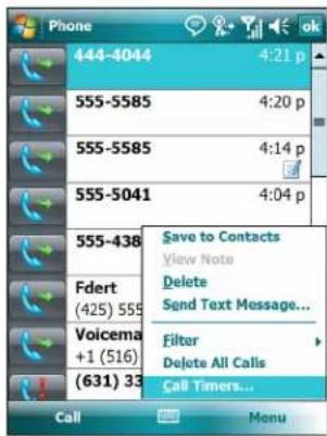
Figure 5-23 Call History - Tools Menu
4. Select Call Timers...
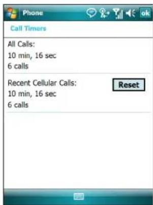
Figure 5-24 Call History - Call Timers
- Tap Reset. (The All Calls: counter cannot be reset.)
- Tap ok to exit the Call Timers window.
Deleting Call History Items by Call Date
- Tap Start > Phone or press the green phone key on the MC75's keypad to display the Phone keypad.
- From the Phone keypad, tap Call History.
- Tap Menu > Call Timers...
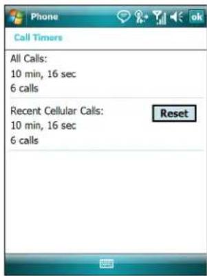
Figure 5-25 Call History - Call Timers
- In the Delete call history items older than: drop-down list select a time period on which to base deletion of stored items.
- Tap ok to exit the Call Timers window.
Deleting All Call History Items
- Tap Start > Phone or press the green phone key on the MC75's keypad to display the Phone keypad.
- From the Phone keypad, tap Call History.
- TapMenu.

Figure 5-26 Call History - Tools Menu
- Select Delete all calls.
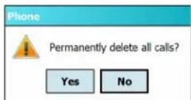
Figure 5-27 Call History - Delete All Dialog
- Tap Yes.
- Tap ok to exit the Call History window.
Viewing Call Status
- Tap Start > Phone or press the green phone key on the MC75's keypad to display the Phone keypad.
- From the Phone keypad, tap Call History.
- Tap an entry. The Call Status window appears.
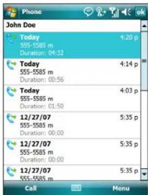
Figure 5-28 Call History - Detail

NOTE When more than one call is on the phone line, only the duration of the first call is recorded.
- Tap ok and then ok to exit.
Using the Call History Menu
Use the Call History menu to dial voice mail, access the Activation Wizard, save to contacts, view a note, delete a listing, send an SMS, and make a call.
- Tap Start > Phone or press the green phone key on the MC75's keypad to display the Phone keypad.
- From the Phone keypad, tap Call History.
- Tap and hold an item in the list.
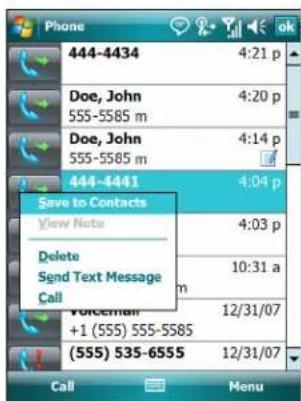
Figure 5-29 Call History - Menu
-
Select an applicable item from the menu, as needed.
-
Depending on the item selected, the appropriate window displays. For example, select Send SMS to display the Inbox window.
- Tap ok to exit the Call History window.
Swapping Calls on an MC7506/96
To move between two or more phone calls:
- Tap Start > Phone or press the green phone key on the MC75's keypad to display the Phone keypad.
- Enter the first phone number and press Talk. When the call connects, Hold appears on the keypad.
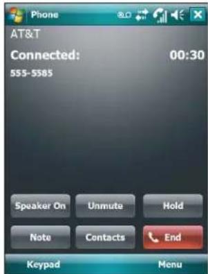
MC7506/96
Figure 5-30 Call Swapping - Hold
- Tap Hold on to place the first number on hold.
- Enter the second number and tap Talk.
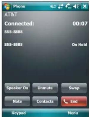
Figure 5-31 Call Conferencing - Conferencing
- Tap Swap to move from one call to the other.
- Tap End or press the red phone key on the MC75 keypad to end each call.
Swapping Calls on an MC7508/98
To swap between two incoming phone calls:
- Tap Answer to connect to the first call.
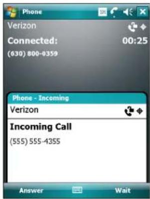
Figure 5-32 Answer a Call
-
When a second call arrives, tap Answer. The first call is placed on hold.
-
Tap Talk to swap from one call to the other.
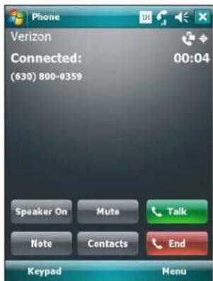
Figure 5-33 Call Swapping
- Tap End or press the red phone key on the MC75 keypad to end active call. The remaining call re-connects, tap Answer to connect to the call.
- Tap End or press the red phone key on the MC75 keypad to end the last call.
Conference Calling on an MC7506/96

NOTE Conference Calling and the number of conference calls allowed may not be available on all services. Please check with your service provider for Conference Calling availability.
To create a conference phone session with multiple people:
-
Tap Start > Phone or press the green phone key on the MC75's keypad to display the Phone keypad.
-
Enter the first phone number and press Talk. When the call connects, Hold appears on the keypad.
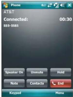
Figure 5-34 Conference Call - Hold
- Tap Hold to place the first call on hold.
- Enter the second phone number and tap Talk.
- After the call is answered, tap Menu > Conference to place the calls in conference mode.
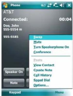
Figure 5-35 Creating a Conference Call
- Tap Hold to place the conference on hold.
- Enter another phone number and tap Talk.
- After the call is answered, tap Menu > Conference to place all the calls in conference mode.
- Repeat steps 6 through 8 for up to six phone numbers.
- Tap End or press the red phone key on the MC75 keypad to end the conference call.

NOTE To speak privately with one party during a conference call, tap Menu > Private. To include all parties again, tap Menu > Conference.
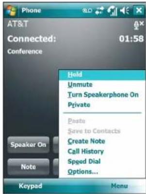
Figure 5-36 Creating a Private Call
Three-way Calling on an MC7508/98

NOTE Three-way Calling may not be available on all services. Please check with your service provider for availability.
To create a three-way phone session with two people and you as the initiator:
- Tap Start > Phone or press the green phone key on the MC75's keypad to display the Phone keypad.
- Enter the first phone number and press Talk.
- To call a second person, tap Keypad. Enter the second number and tap Talk.
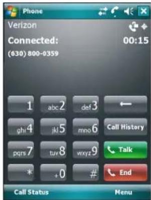
Figure 5-37 Calling Another Person
- When the second person answers the call, tap Talk to create a three-way calling session.
- Tap Talk to drop the last call.
- Tap End to drop the first call.
Text Messaging
Use the Text Messages window to send and receive text messages to and from mobile phones. The text can contain words, numbers, or an alphanumeric combination no longer than 160 characters.
Short text messages delivered over mobile networks transmit from the sending MC75, are stored in a central short message center, then forwarded to the destination mobile device. If the recipient is not available, the message is stored and can be sent later.
Viewing Text Messages
To view a text message:
You can view a text message whether the phone is on or off. When the phone is on, you can view a text message from its notification callout. Tap the text message notification icon on the navigation bar to display the message.
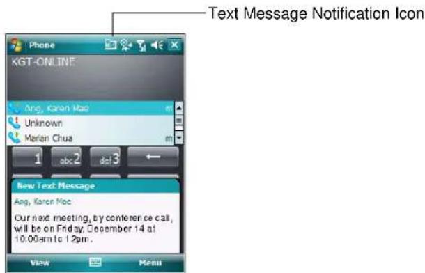
Figure 5-38 New Text Message Notification
The Caller Identification feature matches incoming text message numbers with those stored in Contacts so you know who is sending you a message. Furthermore, the New Text Message dialog box gives you the option to call the sender or save, dismiss, or delete the message.
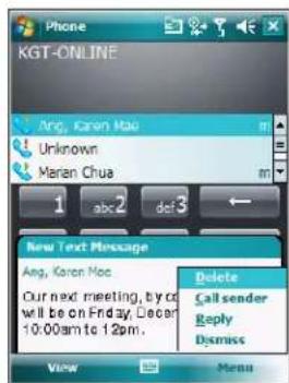
Figure 5-39 New Text Message Options
When the phone function is off, you can still view received text message in Messaging:
- Tap Start > Messaging > Text Messages, or on the Today screen, tap Text Messages.
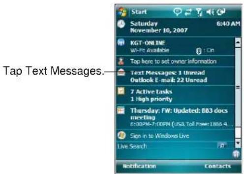
Figure 5-40 Text Messaging on Today Screen
The Messaging window appears.
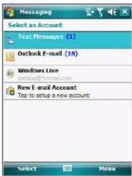
Figure 5-41 Messaging Window
- In the message list, tap a Text Messages.
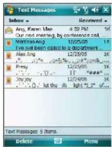
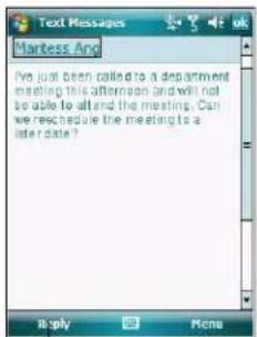
Tap to reply the message.
Figure 5-42 Text Messages List

NOTE If the phone is turned off and you tried to call the sender, send a reply, or forward the message, you are prompted to turn the phone function on.
Sending a Text Message
To create a text message:
- On the Phone screen, select a contact name that you want to send a message to.
2. Tap Menu > Send Text Message.
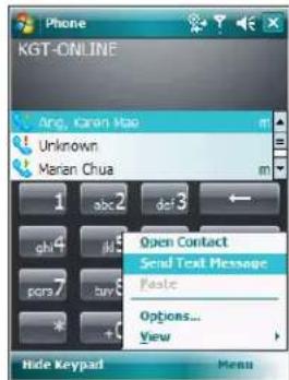
Figure 5-43 Phone Screen Contact List
3. Compose your message.
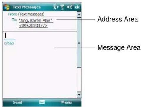
Figure 5-44 Create Text Message
- The auto-correct feature automatically fixes common spelling errors as you type so your messages are more accurate.
• The character counter lets you see and control the size of the message as you compose. - If you want to know if your text message was received, tap Menu > Message Options, then select the Request SMS text message delivery notification check box.
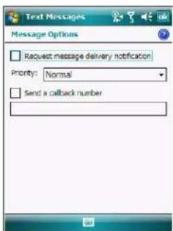
Figure 5-45 Message Options Window
4. Tap Send when you've finished the message.
If the phone is turned on, your text message is sent. If it's off, you are prompted to turn on the phone. If you do so, the message is sent; otherwise when you tap ok, the message is saved in the Drafts folder and sent when the phone is turned on.
If you are out of coverage area, the message is saved in the Drafts folder and sent when you return to a coverage area.

NOTE On MC7506 and MC7596 devices, the message remains in the Drafts folder and has to be manually re-sent when you return to a coverage area.
Using a Dual Line SIM

NOTE Dual Line SIM support is only available on MC7506 and MC7596 configurations.
Check with your service provider for availability.
Dual line SIM cards allow for two phone lines on a single card. For example, one line can be a business phone line and the other a personal phone line.
To switch between phone lines:
- Tap Start > Programs > SIM Toolkit.
Figure 5-46 SIM UI Window
- Select Dual and then tap Select.
Figure 5-47 Change Phone Line
- Select Change and then tap Select.
- If applicable, sign in with the PIN number for the other line.
5 - 28 MC75 User Guide
Chapter 6 Accessories
Introduction
MC75 accessories, listed below, provide a variety of product support capabilities.
- Four Slot Ethernet Cradle - Charges the MC75 main battery and connects the MC75 with an Ethernet network.
- Four Slot Charge Only Cradle - Charges up to four MC75 devices.
- Single Slot USB/Serial Cradle - Charges the MC75 main battery and a spare battery. Synchronizes the MC75 with a host computer through a USB connection.
- Vehicle Cradle - Provides secure mounting of the MC75 in a vehicle. Charges the MC75 and a spare battery. Provides a serial port for data communication between an MC75 and an external device.
- Four Slot Battery Charger - Charges spare standard and high capacity batteries.
- Auto Charge Cable - Plugs into a vehicle cigarette lighter to charge the MC75 while on the road.
- Charge Only Cable - Provides power to the MC75.
- DEX Cable - Enables the transmission of data between the MC75 and a customer's inventory system at the time of delivery.
- Modem Inverter Cable - Connects the MC75 to the modem dongle.
- Modem Dongle - provide modem connectivity.
- Printer Cables - Connects the MC75 to a printer.
- Serial Cable - Provides serial communication from cradle with a host computer.
- Serial Charging Cable - Provides power to the MC75 and serial communication with a host computer.
- USB Cable - Provides USB communication from cradle with a host computer.
- USB Charging Cable - Provides power to the MC75 and USB communication with a host computer.
- Belt Mounted Rigid Holster - Holds the MC75 when not in use.
- Belt Mounted Fabric Holster - Provides additional protection for the MC75.
- Headset - Used in noisy environments.
- MSR - Snaps on to the MC75 and adds magstripe read capabilities.
Single Slot USB/Serial Cradle
This section describes how to use a Single Slot USB/Serial cradle with the MC75. For USB communication setup procedures refer to the MC75 Integrator Guide.
The Single Slot USB/Serial Cradle:
- Provides 5.4 VDC power for operating the MC75.
- Synchronizes information between the MC75 and a host computer. Refer to the MC75 Integrator Guide for information on setting up a partnership between the MC75 and a host computer.
• Charges the MC75's battery.
• Charges a spare battery.
Charging the MC75 Battery
Connect the cradle to power. Insert the MC75 into the slot to begin charging.
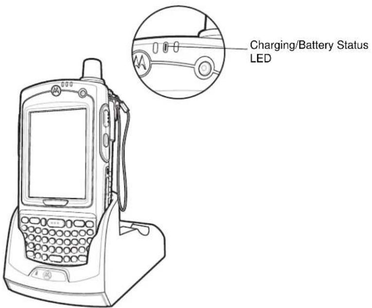
Figure 6-1 MC75 Battery Charging
Charging the Spare Battery
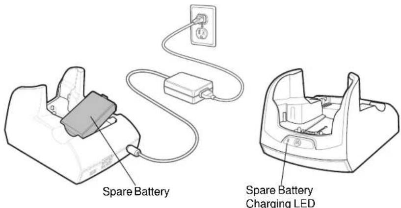
Figure 6-2 Spare Battery Charging
Battery Charging Indicators
The Single Slot USB/Serial Cradle charges the MC75's main battery and a spare battery simultaneously.
The MC75's charge LED indicates the status of the battery charging in the MC75. See Table 1-2 on page 1-7 for charging status indications.
The spare battery charging LED on the cradle indicates the status of the spare battery charging in the cradle. See Table 6-1 for charging status indications.
The 3600 mAh battery fully charges in less than five hours and the 4800 mAh battery fully charges in less than seven hours.
Charging Temperature
Charge batteries in temperatures from 0^ C to 40^ C ( 32^ F to 104^ F). Charging is intelligently controlled by the MC75.
To accomplish this, for small periods of time, the MC75 or accessory alternately enables and disables battery charging to keep the battery at acceptable temperatures. The MC75 or accessory indicates when charging is disabled due to abnormal temperatures via its LED. See Table 1-2 on page 1-7 and Table 6-1.
Table 6-1 Spare Battery LED Charging Indicators
| Spare Battery LED (on cradle) | Indication |
| Off Battery is not charging; battery is not inserted correctly in the cradle; cradle is not powered | |
| Slow Blinking Amber Spare battery is charging. | |
| Solid Amber Charging complete. | |
| Fast Blinking Amber Charging error. |
Four Slot Ethernet Cradle
This section describes how to set up and use a Four Slot Ethernet cradle with the MC75. For cradle communication setup procedures refer to the MC75 Integrator Guide.
The Four Slot Ethernet cradle:
- Provides 5.4 VDC power for operating the MC75.
- Connects the MC75 (up to four) to an Ethernet network.
• Simultaneously charges up to four MC75 devices.
Charging
Insert the MC75 into a slot to begin charging.
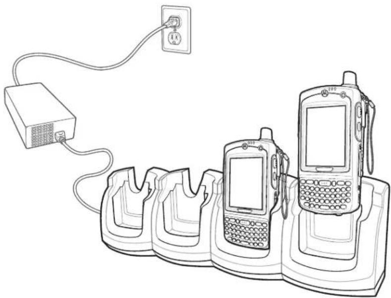
natural_image
Line drawing of a mobile phone setup with three generations connected to a power outlet (no text or symbols)Figure 6-3 MC75 Battery Charging
Battery Charging Indicators
The MC75's charge LED shows the status of the battery charging in the MC75. See Table 1-2 on page 1-7 for charging status indications.
The 3600 mAh battery fully charges in less than five hours and the 4800 mAh battery fully charges in less than seven hours.
Charging Temperature
Charge batteries in temperatures from 0°C to 40°C (32°F to 104°F). Charging is intelligently controlled by the MC75.
To accomplish this, for small periods of time, the MC75 or accessory alternately enables and disables battery charging to keep the battery at acceptable temperatures. The MC75 or accessory indicates when charging is disabled due to abnormal temperatures via its LED. See Table 1-2 on page 1-7.
Four Slot Charge Only Cradle
This section describes how to set up and use a Four Slot Charge Only cradle with the MC75.
The Four Slot Charge Only cradle:
- Provides 5.4 VDC power for operating the MC75.
• Simultaneously charges up to four MC75 devices.
Charging
Insert the MC75 into a slot to begin charging.
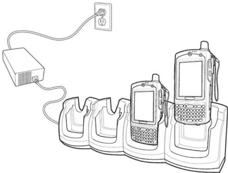
natural_image
Line drawing of a mobile phone setup with three generations connected to a power outlet (no text or symbols)Figure 6-4 MC75 Battery Charging
Battery Charging Indicators
The MC75's charge LED shows the status of the battery charging in the MC75. See Table 1-2 on page 1-7 for charging status indications.
The 3600 mAh battery fully charges in less than five hours and the 4800 mAh battery fully charges in less than seven hours.
Charging Temperature
Charge batteries in temperatures from 0°C to 40°C (32°F to 104°F). Charging is intelligently controlled by the MC75.
To accomplish this, for small periods of time, the MC75 or accessory alternately enables and disables battery charging to keep the battery at acceptable temperatures. The MC75 or accessory indicates when charging is disabled due to abnormal temperatures via its LED. See Table 1-2 on page 1-7.
VCD7X00 Vehicle Cradle
This section describes how to use a VCD7X00 vehicle cradle with the MC75. For cradle installation and communication setup procedures refer to the MC75 Integrator Guide.
Once installed in a vehicle, the cradle:
• holds the MC75 securely in place
• provides power for operating the MC75
- provides a serial port for data communication between an MC75 and an external device (e.g., a printer)
• re-charges the battery in the MC75
• re-charges a 3600 mAh or 4800 mAh spare battery.
Charging the MC75 Battery
Insert the MC75 into the vehicle cradle to begin charging. A click indicates that the MC75 button release locking mechanism is enabled and the MC75 is locked in place.
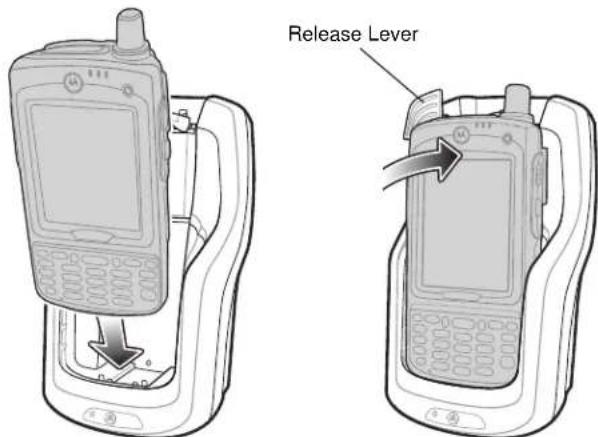
Figure 6-5 MC75 Battery Charging

CAUTION Ensure the MC75 is fully inserted in the cradle. Lack of proper insertion may result in property damage or personal injury. Motorola is not responsible for any loss resulting from the use of the products while driving.
Removing the MC75
To remove the MC75, hold back the release lever on the cradle and pull the MC75 up and out of the cradle.
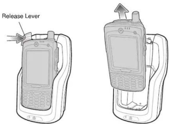
Figure 6-6 Removing the MC75
Charging the Spare Battery
Insert a spare battery to begin charging:
- Lift the battery release lever.
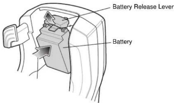
Figure 6-7 Inserting the Spare Battery
- Insert the spare battery in the spare battery charging slot in the cradle with the charging contacts facing up and to the rear of the cradle.
- Release the battery release lever. The battery release lever locks the spare battery into place.
To remove a spare battery, hold back the battery release lever and lift the battery from the spare battery slot.
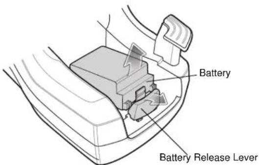
Figure 6-8 Removing the Spare Battery
Battery Charging Indicators
The Vehicle Cradle charges the MC75's main battery and a spare battery simultaneously.
The MC75's charge LED indicates the status of the battery charging in the MC75. See Table 1-2 on page 1-7 for charging status indications.
The spare battery charging LED on the cradle indicates the status of the spare battery charging in the cradle. See Table 6-2 for charging status indications.
The 3600 mAh battery fully charges in less than five hours and the 4800 mAh battery fully charges in less than seven hours.
Charging Temperature
Charge batteries in temperatures from 0^ C to 40^ C ( 32^ F to 104^ F). Charging is intelligently controlled by the MC75.
To accomplish this, for small periods of time, the MC75 or accessory alternately enables and disables battery charging to keep the battery at acceptable temperatures. The MC75 or accessory indicates when charging is disabled due to abnormal temperatures via its LED. See Table 1-2 on page 1-7 and Table 6-2.
Table 6-2 Vehicle Cradle Spare Battery LED Charging Indicators
| Spare Battery LED(on cradle) | Indication |
| Off Battery is not charging; battery is not inserted correctly in the cradle; cradle is not powered | |
| Slow Blinking Amber Spare battery is charging. | |
| Solid Amber Charging complete. | |
| Fast Blinking Amber Charging error. | |
Four Slot Battery Charger
This section describes how to use the Four Slot Battery Charger to charge up to four MC75 batteries.
MC75 Battery Shim Installation
Before charging a spare battery, snap the MC75 shim into the battery slot as shown in Figure 6-9.
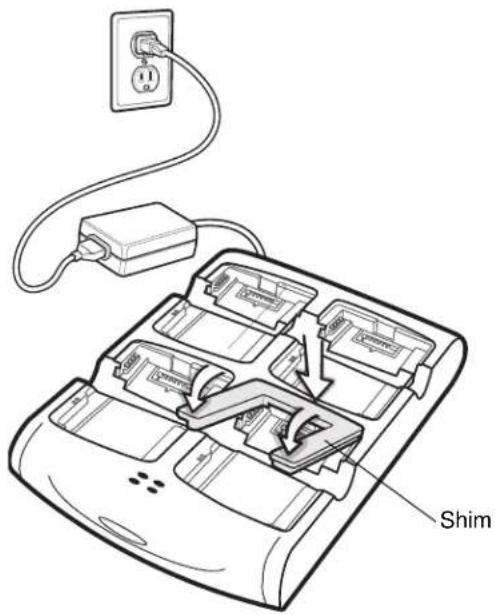
Figure 6-9 MC75 Battery Shim Installation

NOTE To purchase additional shims, contact your local account manager or Motorola, Inc. Part number: KT-76490-01R.
Spare Battery Charging
- Connect the charger to a power source.
- Insert the spare battery into a spare battery charging well and gently press down on the battery to ensure proper contact.
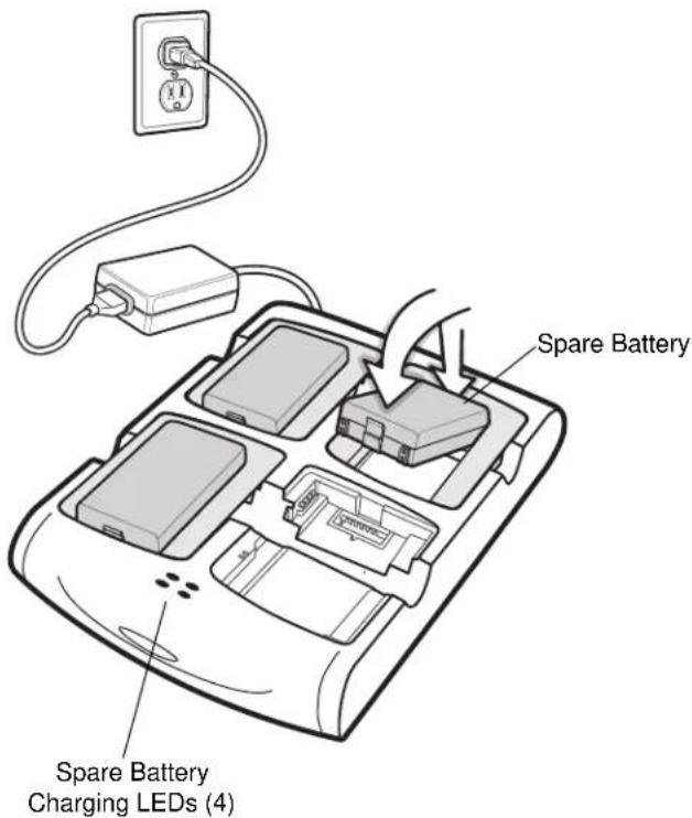
Figure 6-10 Four Slot Battery Charger
Battery Charging Indicators
The charger has an amber LED for each battery charging well. See Table 6-3 for charging status indications. The 3600 mAh battery fully charges in less than five hours and the 4800 mAh battery fully charges in less than seven hours.
Charging Temperature
Charge batteries in temperatures from 0°C to 40°C (32°F to 104°F). Charging is intelligently controlled by the MC75.
To accomplish this, for small periods of time, the charger alternately enables and disables battery charging to keep the battery at acceptable temperatures. The charger indicates when charging is disabled due to abnormal temperatures via its LED. See Table 6-3.
Table 6-3 Spare Battery LED Charging Indicators
| LED Indication | |
| Off No spare battery in slot; battery is not charging; battery is not inserted correctly in the charger; charger is not powered. | |
| Slow Blinking Amber Spare battery is charging. | |
| Solid Amber Charging complete. | |
| Fast Blinking Amber Charging error. | |
Magnetic Stripe Reader (MSR)
This section describes how to set up and use the snap-on MSR with the MC75. The MSR snaps on to the bottom of the MC75 and removes easily when not in use.
When attached to the MC75, the MSR allows the MC75 to capture data from magnetic stripe cards. To download MSR data capture software, visit the Motorola web site at http://www.symbol.com/support.
With the MSR attach, the MC75 can still be charged by placing the MC75 with MSR into a cradle or connecting to a charging cable.
Attaching and Removing the MSR
To attach, slide the MSR onto the bottom of the MC75 and secure by snapping the arms into the MC75 housing.
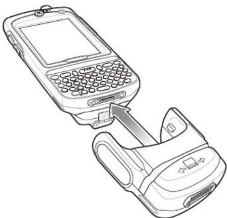
natural_image
Line drawing of a mobile phone connected to a device (no text or symbols present)Figure 6-11 MSR Installation
To remove the MSR open the arms and pull the MSR from the MC75.

NOTE When attaching a cable with a cup connector through the MSR to charge the device, you cannot swipe cards.
Using the MSR
Install an MSR enabled application onto the MC75.
To use the MSR:
-
Attach the MSR to the MC75.
-
Power on the MC75.
-
Launch the MSR application.
-
Swipe the magnetic stripe card through the MSR, with the magnetic stripe on the card facing down. Swipe the card in either direction, from left to right or from right to left. For best results, gently press down on the card while swiping to ensure contact with the bottom of the reader.
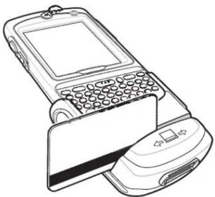
natural_image
Line drawing of a vintage mobile phone with a card slot and keypad (no text or symbols)Figure 6-12 Magnetic Stripe Card Swiping
- The application indicates if the data has been read correctly.
Debit Card Reader
The DCR7X00-100R Debit Card Reader (DCR) snaps onto the bottom of the MC70/MC75 mobile computer to allow easy data capture with the swipe of a magnetic stripe card and personal identification number (PIN) entry using a numeric keypad. This guide describes how to install and use the DCR.
Getting Started
When using the DCR for the first time, charge the DCR in a cradle for a minimum of three hours.
Installation
- Align the DCR with the bottom of the MC75 and push up until the locking tabs snap into place.
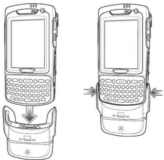
Figure 6-13 DCR Installation
- Pull on the DCR to ensure it is securely connected to the MC75.
Removal
To remove the DCR from the MC75, push in the bottom of the two locking tabs and pull the DCR from the MC75.
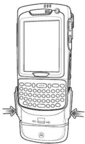
natural_image
Line drawing of a vintage mobile phone with front panel, keypad, and buttons (no text or symbols)Figure 6-14 DCR Removal
Credit Card Transactions
Launch a transaction application on the MC75. In the application, select Credit Card transaction.
Swipe the credit card through the magnetic stripe reader (MSR) slot, orienting the magnetic stripe as shown. Data encoded on the credit card is captured and, depending on the application, may display in an application data field.
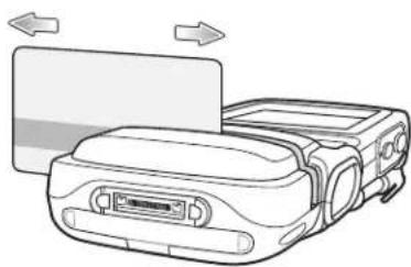
natural_image
Line drawing of a device with arrows indicating motion or movement, no text or symbols presentFigure 6-15 Swipe Card

NOTE Swipe the card in either direction, from left to right, or right to left. For best results, gently press down on the card while swiping to ensure contact with the bottom of the slot.
Debit Card Transactions
Launch a transaction application on the MC75. In the application, select Debit Card transaction.
Swipe the debit card through the MSR slot, orienting the magnetic stripe as shown. Data encoded on the debit card is captured and, depending on the application, may display in an application data field.
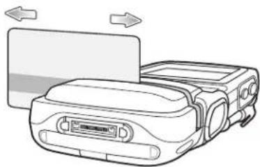
natural_image
Line drawing of a device with arrows indicating motion or transformation (no text or symbols)Figure 6-16 Swipe Card

NOTE Swipe the card in either direction, from left to right, or right to left. For best results, gently press down on the card while swiping to ensure contact with the bottom of the slot.
Turn the MC75 over and present the DCR keypad to the customer. The customer enters their PIN following the instructions on the DCR display.
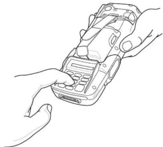
natural_image
Line drawing of two hands inserting a mobile phone into a device (no text or symbols)Figure 6-17 Enter PIN on DCR
Keypad
The back of the DCR contains a display and a numeric keypad for entering data.
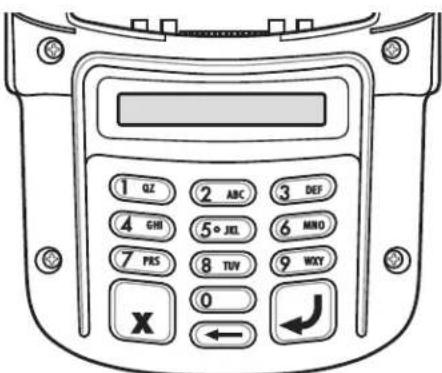
Figure 6-18 DCR Keypad
Table 6-4 Keypad Key Descriptions
| Key Description | |
| Numeric Used to enter PIN. | |
 | |
| Cancel Cancels the current transaction. | |
 | |
| Clear Clears the entered data. | |
 | |
| Enter Submits the entered data. | |
 | |
Display Messages
The follow messages may appear on the DCR display:
ENTER PIN - A PIN is required to complete the transaction.
PIN ERR - The entered PIN is not between 4 and 12 characters.
CANCELED - The transaction was cancelled by the user.
COMPLETE - The transaction was completed.
KEYCLEAR - The DCR was tampered with or the battery completely discharged. The DCR must have the key re-injected. See your system administrator.
BATT OK - Battery is significantly charged.
BATT LOW - Battery charge is low. Re-charge as soon as possible.
STAND BY - DCR is performing a firmware check. This occurs if it has been powered off for more than 24 hours.
Check the DCR Battery Level
When the DCR is not used for extended periods of time or in storage it must be charged periodically to maintain the battery charge. Motorola recommends charging the DCR once every three months.
If the DCR battery fully discharges the debit function will be inoperable but the MSR will still function for credit card transactions. Return the DCR for service.

NOTE While the DCR is being used in normal operation (application is accessing the DCR port), the DCR charges from the MC75.
To check the battery level:
-
Remove the DCR from the MC75.
-
Press and hold the 5 key until the battery status displays on the DCR display.
• BATT OK - Battery is significantly charged
• BATT LOW - Battery charge is low.
If BATT LOW displays, charge the DCR for approximately three hours.
To charge the DCR, place it in a cradle or connect it to a charging cable. The DCR also charges when connected to the MC75 and the transaction application is running.
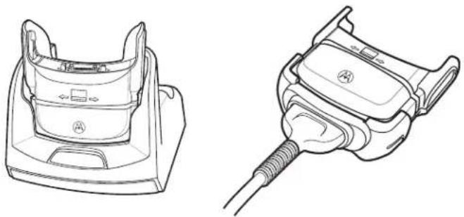
natural_image
Technical line drawings of two different automotive components: a front-mounted device and a connected electrical plug (no text or symbols present)Figure 6-19 Charging the DCR
Headset
Use the headset to communicate via Voice-Over-IP (VOIP) or for audio playback and telephony applications. To connect the headset, remove the plug from the headset jack at the top of the MC75 and insert the headset connector. Contact a Motorola representative for compatible headsets.
For best performance, Motorola recommends a 2.5mm jack headset, p/n 50-11300-050R.
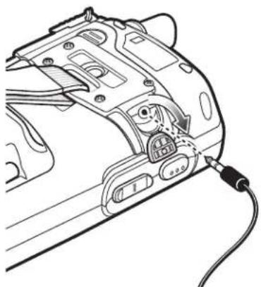
natural_image
Technical line drawing of a camera body panel with attached cable (no text or symbols)Figure 6-20 Headset Connection
Cables
This section describes how to set up and use the cables. The cables are available with a variety of connection capabilities.
The following communication/charge cables are available:
- Serial (RS232) Charge cable (9-pin D female with power input receptacle)
- USB Client Charge cable (standard-A connector and a barrel receptacle for power)
- Auto charge cable
- DEX cable
- Modem inverter cable
- Charge only cable.
The following printer cables are available directly from Motorola:
- O'Neil Printer cable
- Zebra Printer cable.
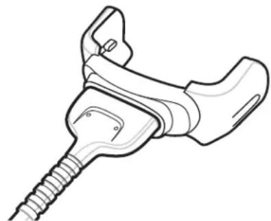
natural_image
Line drawing of a medical or surgical device with a threaded screw and attached clamp (no text or symbols)Figure 6-21 Cables
Communication/charge cables:
- Provide the MC75 with operating and charging power when used with the Motorola approved power supply.
- Synchronize information between the MC75 and a host computer. With customized or third party software, it can also synchronize the MC75 with corporate databases.
- Provide serial connection through the serial pass-through port for communication with a serial device, such as a host computer. For communication setup procedures, refer to the MC75 Integrator Guide.
- Provide USB connection through the USB pass-through port for communication with a USB device, such as a host computer. For communication setup procedures, refer to the MC75 Integrator Guide.
Dedicated printer cables provide communication with a printer.
Battery Charging and Operating Power
The communication/charge cables can charge the MC75 battery and supply operating power.
To charge the MC75 battery:
-
Connect the communication/charge cable power input connector to the Motorola approved power source.
-
Slide the bottom of the MC75 into the connector end of the communication/charge cable and gently press in until it latches into the MC75. The MC75 amber Charge LED indicates the MC75 battery charging status. The 3600 mAh standard battery charges in less than five hours and the 4800 mAh standard battery charges in less than seven hours. See Table 1-2 on page 1-7 for charging status indications.
- When charging is complete, remove the cable by gently pulling the MC75 and the cable apart.
LED Charge Indications
The amber Charge LED on the MC75 indicates battery charging status. See Table 1-2 on page 1-7 for charging status indications.
Charging Temperature
Charge batteries in temperatures from 0^ C to 40^ C ( 32^ F to 104^ F). Charging is intelligently controlled by the MC75.
To accomplish this, for small periods of time, the MC75 or accessory alternately enables and disables battery charging to keep the battery at acceptable temperatures. The MC75 or accessory indicates when charging is disabled due to abnormal temperatures via its LED. See Table 1-2 on page 1-7.4
Chapter 7 Maintenance & Troubleshooting
Introduction
This chapter includes instructions on cleaning and storing the MC75, and provides troubleshooting solutions for potential problems during MC75 operation.
Maintaining the MC75
For trouble-free service, observe the following tips when using the MC75:
- Do not scratch the screen of the MC75. When working with the MC75, use the supplied stylus or plastic-tipped pens intended for use with a touch-sensitive screen. Never use an actual pen or pencil or other sharp object on the surface of the MC75 screen.
Motorola recommends using a screen protector, p/n KT-67525-01R.
- The touch-sensitive screen of the MC75 is glass. Do not to drop the MC75 or subject it to strong impact.
- Protect the MC75 from temperature extremes. Do not leave it on the dashboard of a car on a hot day, and keep it away from heat sources.
- Do not store or use the MC75 in any location that is dusty, damp, or wet.
- Use a soft lens cloth to clean the MC75. If the surface of the MC75 screen becomes soiled, clean it with a soft cloth moistened with a diluted window-cleaning solution.
- Periodically replace the rechargeable battery to ensure maximum battery life and product performance. Battery life depends on individual usage patterns.
- A screen protector is applied to the MC75. Motorola recommends using this to minimize wear and tear. Screen protectors enhance the usability and durability of touch screen displays. Benefits include:
• Protection from scratches and gouges
• Durable writing and touch surface with tactile feel
- Abrasion and chemical resistance
- Glare reduction
- Keeping the device's screen looking new
- Quick and easy installation.
Battery Safety Guidelines
- The area in which the units are charged should be clear of debris and combustible materials or chemicals. Particular care should be taken where the device is charged in a non commercial environment.
- Follow battery usage, storage, and charging guidelines found in the user's guide.
- Improper battery use may result in a fire, explosion, or other hazard.
- To charge the mobile device battery, the battery and charger temperatures must be between +32 °F and +104 °F (0 °C and +40 °C)
- Do not use incompatible batteries and chargers. Use of an incompatible battery or charger may present a risk of fire, explosion, leakage, or other hazard. If you have any questions about the compatibility of a battery or a charger, contact Motorola Enterprise Mobility support.
- For devices that utilize a USB port as a charging source, the device shall only be connected to products that bear the USB-IF logo or have completed the USB-IF compliance program.
- To enable authentication of an approved battery, as required by IEEE1725 clause 10.2.1, all batteries will carry a Motorola hologram. Do not fit any battery without checking it has the Motorola authentication hologram.
- Do not disassemble or open, crush, bend or deform, puncture, or shred.
- Severe impact from dropping any battery-operated device on a hard surface could cause the battery to overheat.
- Do not short circuit a battery or allow metallic or conductive objects to contact the battery terminals.
- Do not modify or remanufacture, attempt to insert foreign objects into the battery, immerse or expose to water or other liquids, or expose to fire, explosion, or other hazard.
- Do not leave or store the equipment in or near areas that might get very hot, such as in a parked vehicle or near a radiator or other heat source. Do not place battery into a microwave oven or dryer.
- Battery usage by children should be supervised.
- Please follow local regulations to promptly dispose of used re-chargeable batteries.
- Do not dispose of batteries in fire.
- Seek medical advice immediately if a battery has been swallowed.
- In the event of a battery leak, do not allow the liquid to come in contact with the skin or eyes. If contact has been made, wash the affected area with large amounts of water and seek medical advice.
- If you suspect damage to your equipment or battery, contact Motorola Enterprise Mobility support to arrange for inspection.
Cleaning

CAUTION Always wear eye protection.
Read warning label on compressed air and alcohol product before using.
If you have to use any other solution for medical reasons please contact Motorola for more information.

WARNING! Avoid exposing this product to contact with hot oil or other flammable liquids. If such exposure occurs, unplug the device and clean the product immediately in accordance with these guidelines.
Materials Required
- Alcohol wipes
- Lens tissue
• Cotton tipped applicators - Isopropyl alcohol
- Can of compressed air with a tube.
Cleaning the MC75
Housing
Using the alcohol wipes, wipe the housing including keys and in-between keys.
Display
The display can be wiped down with the alcohol wipes, but care should be taken not to allow any pooling of liquid around the edges of the display. Immediately dried the display with a soft, non-abrasive cloth to prevent streaking.
Scanner Exit Window
Wipe the scanner exit window periodically with a lens tissue or other material suitable for cleaning optical material such as eyeglasses.
Connector
- Remove the main battery from mobile computer. See Replacing the Main Battery on page 1-11.
- Close battery door.
- Dip the cotton portion of the cotton tipped applicator in isopropyl alcohol.
- Rub the cotton portion of the cotton tipped applicator back-and-forth across the connector on the bottom of the MC75. Do not leave any cotton residue on the connector.
- Repeat at least three times.
- Use the cotton tipped applicator dipped in alcohol to remove any grease and dirt near the connector area.
-
Use a dry cotton tipped applicator and repeat steps 4 through 6.
-
Spray compressed air on the connector area by pointing the tube/nozzle about 12 inch away from the surface. CAUTION: Do not point nozzle at yourself and others, ensure the nozzle or tube is away from your face.
- Inspect the area for any grease or dirt, repeat if required.
Cleaning Cradle Connectors
To clean the connectors on a cradle:
- Remove the DC power cable from the cradle.
- Dip the cotton portion of the cotton tipped applicator in isopropyl alcohol.
- Rub the cotton portion of the cotton tipped applicator along the pins of the connector. Slowly move the applicator back-and-forth from one side of the connector to the other. Do not let any cotton residue on the connector.
- All sides of the connector should also be rubbed with the cotton tipped applicator.
- Spray compressed air in the connector area by pointing the tube/nozzle about 12 inch away from the surface. CAUTION: do not point nozzle at yourself and others, ensure the nozzle or tube is pointed away from your face.
- Ensure that there is no lint left by the cotton tipped applicator, remove lint if found.
- If grease and other dirt can be found on other areas of the cradle, use lint free cloth and alcohol to remove.
- Allow at least 10 to 30 minutes (depending on ambient temperature and humidity) for the alcohol to air dry before applying power to cradle.
If the temperature is low and humidity is high, longer drying time is required. Warm temperature and dry humidity requires less drying time.
Cleaning Frequency
The cleaning frequency is up to the customer's discretion due to the varied environments in which the mobile devices are used. They may be cleaned as frequently as required. However when used in dirty environments it may be advisable to periodically clean the scanner exit window to ensure optimum scanning performance.
Troubleshooting
MC75
Table 7-1 Troubleshooting the MC75
| Problem Cause | Solution | |
| MC75 does not turn on. | Lithium-ion battery not charged. | Charge or replace the lithium-ion battery in the MC75. |
| Lithium-ion battery not installed properly. | Install the battery properly. SeeInstalling the Main Battery on page 1-6. | |
| System crash. | Perform a warm boot. If the MC75 still does not turn on, perform a cold boot. SeeResetting the MC75 on page 2-14. | |
| Rechargeable lithium-ion battery did not charge. | Battery failed. | Replace battery. If the MC75 still does not operate, perform a warm boot, then a cold boot. SeeResetting the MC75 on page 2-14. |
| MC75 removed from cradle while battery was charging. | Insert MC75 in cradle. The 3600 mAh battery fully charges in less than six hours. | |
| Extreme battery temperature. | Battery does not charge if ambient temperature is below 0°C (32°F) or above 40°C (104°F). | |
| Cannot see characters on display. | MC75 not powered on. | Press thePowerbutton. |
| During data communication, no data transmitted, or transmitted data was incomplete. | MC75 removed from cradle or disconnected from host computer during communication. | Replace the MC75 in the cradle, or reattach the communication cable and re-transmit. |
| Incorrect cable configuration. | See the system administrator. | |
| Communication software was incorrectly installed or configured. | Perform setup. Refer to the MC75 Integrator Guide for details. | |
| No sound. Volume setting is low or turned off. | Adjust the volume. SeeAdjusting Volume on page 2-10. | |
| MC75 shuts off. MC75 is inactive. The MC75 turns off after a period of inactivity. If the MC75 is running on battery power, set this period from 1 to 5 minutes, in one-minute intervals. If the MC75 is running on external power, set this period to 1, 2, 5, 10, 15, or 30 minutes.Check the Power window by selecting Start > Settings > System tab and tapping the Power icon. Select the Advanced tab and change the setting for a longer delay before the automatic shutoff feature activates. | ||
| Tapping the window buttons or icons does not activate the corresponding feature. | Battery is depleted. Replace the battery. | |
| Battery is not inserted properly. | Insert the battery properly. See Installing the Main Battery on page 1-6. | |
| Screen is not calibrated correctly. | Re-calibrate the screen. See Calibrating the Screen on page 1-8. | |
| The system is not responding. | Warm boot the system. See Resetting the MC75 on page 2-14. | |
| A message appears stating that the MC75 memory is full. | Too many files stored on the MC75. | Delete unused memos and records. If necessary, save these records on the host computer (or use an SD card for additional memory). |
| Too many applications installed on the MC75. | Remove user-installed applications on the MC75 to recover memory. Select Start > Settings > System tab and tap the Remove Programs icon. Select the unused program and tap Remove. | |
| MC75 keeps powering down to protect memory contents. | The MC75's battery is low. | Recharge the battery. |
| The internal Bluetooth radio is powered on for a long time. | Because this mode requires battery power, power it off when not needed. | |
| The MC75 does not accept scan input. | Scanning application is not loaded. | Load a scanning application on the MC75. See the system administrator. |
| Unreadable bar code. | Ensure the symbol is not defaced. | |
| Distance between exit window and bar code is incorrect. | Place the MC75 within proper scanning range. | |
| MC75 is not programmed for the bar code. | Program the MC75 to accept the type of bar code being scanned. | |
| MC75 is not programmed to generate a beep. | If the MC75 does not beep on a good decode, set the application to generate a beep on good decode. | |
| Battery is low. If the scanner stops emitting a laser beam upon a trigger press, check the battery level. When the battery is low, the scanner shuts off before the MC75 low battery condition notification. Note: If the scanner is still not reading symbols, contact the distributor or Motorola. | ||
Bluetooth Connection
Table 7-2 Troubleshooting Bluetooth Connection
| Problem Cause | Solution | |
| MC75 cannot find any Bluetooth devices nearby. | Too far from other Bluetooth devices. | Move closer to the other Bluetooth device(s), within a range of 10 meters. |
| The Bluetooth device(s) nearby are not turned on. | Turn on the Bluetooth device(s). | |
| The Bluetooth device(s) are not in discoverable mode. | Set the Bluetooth device(s) to discoverable mode. If needed, refer to the device's user documentation for help. | |
| When trying to connect a Bluetooth phone and MC75, the phone thinks a previously paired MC75 is used. | The phone remembers the name and address of the MC75 it last paired with via the Bluetooth radio. | Manually delete the pairing device and name from the phone. Refer to the phone's user documentation for instructions. |
| Can't make my Ericsson R520 phone discoverable. | You attempted to bond with the phone, and when the phone presented a “pairing query,” you entered No. This prevents the phone from being discoverable until it is reset. | Reset the phone by removing its battery. |
| There is a delay in the Bluetooth stack re-initializing during a resume from suspend. | This is normal behavior. | No solution required. |
| The Bluetooth connection drops. | The MC75 suspends and the Bluetooth radio power turns off. | When the MC75 suspends the Bluetooth connection is dropped. Re-connect the Bluetooth connection when the MC75 returns from suspend mode. |
Single Slot USB/Serial Cradle
Table 7-3 Troubleshooting the Single Slot USB/Serial Cradle
| Symptom Possible Cause Action | ||
| LEDs do not light when MC75 or spare battery is inserted. | Cradle is not receiving power. | Ensure the power cable is connected securely to both the cradle and to AC power. |
| MC75 is not seated firmly in the cradle. | Remove and re-insert the MC75 into the cradle, ensuring it is firmly seated. | |
| Spare battery is not seated firmly in the cradle. | Remove and re-insert the spare battery into the charging slot, ensuring it is firmly seated. | |
| MC75 battery is not charging. | MC75 was removed from cradle or cradle was unplugged from AC power too soon. | Ensure cradle is receiving power. Ensure MC75 is seated correctly. Confirm main battery is charging under Start > Settings > System > Power. The 3600 mAh battery fully charges in less than six hours. |
| Battery is faulty. Verify that other batteries charge properly. If so, replace the faulty battery. | ||
| The MC75 is not fully seated in the cradle. | Remove and re-insert the MC75 into the cradle, ensuring it is firmly seated. | |
| Ambient temperature of the cradle is too warm. | Move the cradle to an area where the ambient temperature is between 0°C (32°F) and 35°C (95°F). | |
| Extreme battery temperature. | Battery does not charge if ambient temperature is below 0°C (32°F) or above 40°C (104°F). | |
| Spare battery is not charging. | Battery not fully seated in charging slot. | Remove and re-insert the spare battery in the cradle, ensuring it is firmly seated. |
| Battery inserted incorrectly. | Re-insert the battery so the charging contacts on the battery align with the contacts on the cradle. | |
| Battery is faulty. Verify that other batteries charge properly. If so, replace the faulty battery. | ||
| Ambient temperature of the cradle is too warm. | Move the cradle to an area where the ambient temperature is between 0°C (32°F) and 35°C (95°F). | |
| During data communication, no data transmits, or transmitted data was incomplete. | MC75 removed from cradle during communications. | Replace MC75 in cradle and retransmit. |
| Incorrect cable configuration. | See the system administrator. | |
| Communication software is not installed or configured properly. | Perform setup as described in the MC75 Integrator Guide. | |
Four Slot Ethernet Cradle
Table 7-4 Troubleshooting the Four Slot Ethernet Cradle
| Symptom Cause | Solution | |
| Attempt by the MC75 to ActiveSync failed. | MC75 removed from the cradle while the LED was blinking green. | Wait one minute and reinsert the MC75 in the cradle. This allows the cradle to attempt another synchronization. |
| Using an outdated version of ActiveSync. | Visit http://www.microsoft.com for the latest ActiveSync software. | |
| ActiveSync on the host computer has not yet closed the previous ActiveSync session. | Wait one minute and reinsert the MC75 in the cradle. This allows the cradle to attempt another synchronization. | |
| Incorrect cable configuration. | Ensure the correct cable (Ethernet) is used with the cradle. | |
| Communication software improperly configured. | Perform setup as described in the MC75 Integrator Guide. | |
| MC75 ActiveSync disabled or not configured to accept network connection. | On the MC75, tap Start > ActiveSync > Tools > Options > Options button. Then, uncheck the Enable PC sync using this connection: check box. | |
| Host ActiveSync disabled or not configured to accept network connection. | On the host computer, check File > Connection Settings > Allow network (Ethernet) Server Connection with this desktop computer. | |
| During communication, no data transmits, or transmitted data was incomplete. | MC75 removed from cradle during communications. | Replace MC75 in cradle and retransmit. |
| MC75 has no active connection. | An icon is visible in the status bar if a connection is currently active. | |
| Battery is not charging. | MC75 removed from the cradle too soon. | Replace the MC75 in the cradle. The 3600 mAh battery fully charges in less than six hours. Tap Start > Settings > System > Power to view battery status. |
| Battery is faulty. Verify that other batteries charge properly. If so, replace the faulty battery. | ||
| MC75 is not inserted correctly in the cradle. | Remove the MC75 and reinsert it correctly. Verify charging is active. Tap Start > Settings > System > Power to view battery status. | |
| Ambient temperature of the cradle is too warm. | Move the cradle to an area where the ambient temperature is between 0°C (32°F) and 35°C (95°F). | |
Vehicle Cradle
Table 7-5 Troubleshooting the Vehicle Cradle
| Symptom Possible Cause Action | ||
| MC75 battery charging LED does not light up. | Cradle is not receiving power. | Ensure the power input cable is securely connected to the cradle's power port. |
| MC75 battery is not recharging. | MC75 was removed from the cradle too soon. | Replace the MC75 in the cradle. The 3600 mAh battery fully charges in less than six hours. |
| Battery is faulty. Replace the battery. | ||
| MC75 is not placed correctly in the cradle. | Remove the MC75 from the cradle, and re-insert correctly. If the battery still does not charge, contact customer support.The MC75 battery charging LED slowly blinks amber when the MC75 is correctly inserted and charging. | |
| Ambient temperature of the cradle is too warm. | Move to an area where the ambient temperature is between 0°C and 35°C. | |
| No data transmitted, or transmitted data was incomplete. | MC75 removed from cradle during communication. | Replace MC75 in cradle and retransmit. |
| No null modem cable was used. | Some external devices require a null modem cable. Retransmit using a null modem cable. | |
| Incorrect cable configuration. | See the system administrator. | |
| Cable missing or disconnected. | Re-connect cable. | |
Four Slot Battery Charger
Table 7-6 Troubleshooting The Four Slot Battery Charger
| Symptom Possible Cause Action | |
| Battery not charging. Battery was removed from the charger or charger was unplugged from AC power too soon. | Re-insert the battery in the charger or re-connect the charger's power supply. The 3600 mAh battery fully charges in less than six hours. |
| Battery is faulty. Verify that other batteries charge properly. If so, replace the faulty battery. | |
| Battery contacts not connected to charger. | Verify that the battery is seated in the battery well correctly with the contacts facing down. |
| Ambient temperature of the cradle is too warm. | Move the cradle to an area where the ambient temperature is between 0°C and 35°C. |
Cables
Table 7-7 Troubleshooting the Cables
| Symptom Possible Cause Action | ||
| MC75 battery is not charging. | MC75 was disconnected from AC power too soon. | Connect the power cable correctly. Confirm main battery is charging under Start > Settings > System > Power. The 3600 mAh battery fully charges in less than six hours. |
| Battery is faulty. Verify that other batteries charge properly. If so, replace the faulty battery. | ||
| The MC75 is not fully attached to power. | Detach and re-attach the power cable to the MC75, ensuring it is firmly connected. | |
| During data communication, no data transmits, or transmitted data was incomplete. | Cable was disconnected from MC75 during communications. | Re-attach the cable and retransmit. |
| Incorrect cable configuration. | See the system administrator. | |
| Communication software is not installed or configured properly. | Perform setup as described in the MC75 Integrator Guide. | |
Magnetic Stripe Reader
Table 7-8 Troubleshooting the Magnetic Stripe Reader
| Symptom Possible Cause Action | ||
| MSR cannot read card. | MSR removed from MC75 during card swipe. | Reattach MSR to MC75 and reswipe the card. |
| Faulty magnetic stripe on card. | See the system administrator. | |
| MSR application is not installed or configured properly. | Ensure the MSR application is installed on the MC75.Ensure the MSR application is configured correctly. | |
| MC75 battery is not charging. | MC75 was removed from MSR or MSR was unplugged from AC power too soon. | Ensure MSR is receiving power. Ensure MC75 is attached correctly. Confirm main battery is charging under Start > Settings > System > Power. The 3600 mAh battery fully charges in less than six hours. |
| Battery is faulty. Verify that other batteries charge properly. If so, replace the faulty battery. | ||
| The MC75 is not fully attached to the MSR. | Detach and re-attach the MSR to the MC75, ensuring it is firmly connected. | |
| During data communication, no data transmits, or transmitted data was incomplete. | MC75 detached from MSR during communications. | Reattach MC75 to MSR and retransmit. |
| Incorrect cable configuration. | See the system administrator. | |
| Communication software is not installed or configured properly. | Perform setup as described in the MC75 Integrator Guide. | |
7 - 14 MC75 User Guide
Appendix A Technical Specifications
MC75 Technical Specifications
The following tables summarize the MC75's intended operating environment and technical hardware specifications.
MC75
Table A-1 MC75 Technical Specifications
| Item Description | |
| Physical Characteristics | |
| Dimensions Length: 17.9 cm (7.05 in.)Width: 8.4 cm (3.30 in.)Depth: 4.4 cm (1.70 in.) | |
| Weight 422 grams (14.90 oz) - with 3600 mAh battery446g (15.70 oz) - with 4800 mAh battery | |
| Display Transflective color 3.5” VGA with backlight, TFT-LCD, 65K colors,480 W x 640 L (VGA size) | |
| Touch Panel Glass analog resistive touch | |
| Backlight LED backlight | |
| Main Battery Rechargeable Lithium Ion 3.7V, 3600 mAh Smart Battery | |
| Backup Battery NiMH battery (rechargeable) 15 mAh 2.4V (not user-accessible) | |
| Expansion Slot User accessible microSD slot (with secure cover). | |
| Network Connections Ethernet (via cradle)Full-speed USB, host or client, Bluetooth | |
| Note 1: Total output power can be either USB or serial or a combination of both that cannot exceed 200 mA. | |
| Item | Description |
| Notification Vibrator and LED | |
| Keypad Options 26 key numeric | 44 key QWERTY, 44 key AZERTY, 44 key QWERTZ |
| Audio Speaker, receiver, microphone | headset jack, software support for full duplex record and playback (stereo) |
| Performance Characteristics | |
| CPU XScaleTM Bulverde PXA270 | processor at 624 MHz |
| Operating System | Microsoft® Windows MobileTM 6 |
| Memory 128MB RAM/256MB FLASH | |
| Interface/Communications RS-232 | USB 1.1, IrDA |
| Output Power (Note 1) USB: 5 VDC @ 200 mA max.Serial: 5 VDC @ 200 mA max. | |
| User Environment | |
| Operating Temperature -10°C to 50°C (14°F to 122°F) | |
| Storage Temperature -40°C to 60°C (-40°F to 140°F) - without battery | |
| Charging Temperature 32°F to 104°F / 0°C to 40°C | |
| Humidity 95% non-condensing | |
| Drop Specification | 5 ft. drop to concrete, 2 drops per 6 sides at ambient temperature 23°C (73°F).4 ft. drop to concrete, 6 drops per 6 sides over operating temperature range. |
| Electrostatic Discharge (ESD) | +/-15kVdc air discharge, +/-8kVdc direct discharge, +/-8kVdc indirect discharge |
| Sealing | IP54 |
| Wireless WAN Data and Voice Communications | |
| Wireless Wide Area Network (WWAN) radios | MC7506 and MC7596: GSM: 3G HSDPA (850, 900, 1800, 1900 and 2100 MHz)MC7508 and MC7598: CDMA: EVDO Rev A (800 and 1900 MHz) |
| GPS Integrated Assisted-GPS (A-GPS) | |
| Wireless LAN Data and Voice Communications | |
| Wireless Local Area Network (WLAN) radio | Tri-mode IEEE® 802.11a/b/g |
| Data Rates Supported | 1, 2, 5.5, 6, 9, 11, 12, 18, 24, 36, 48, and 54 Mbps |
| Operating Channels Chan 8-169 (5040 – 5845 MHz)Chan 1-13 (2412-2472 MHz) Chan 14 (2484 MHz) Japan onlyActual operating frequencies depend on regulatory rules and certification agency | |
| Security WPA2, WPA, WEP (40 or 128 bit), TKIP, TLS, TTLS (MS-CHAP), TTLS(MS-CHAP v2), TTLS (CHAP), TTLS-MD5, TTLS-PAP, PEAP-TLS, PEAP(MS-CHAP v2), AES, LEAP | |
| Spreading Technique Direct Sequence Spread Spectrum (DSSS) and Orthogonal Frequency Division Multiplexing (OFDM) | |
| Antenna Internal for WLAN, Bluetooth and GPS, external for WWAN | |
| Voice Communication Integrated Voice-over-IP ready (P2P, PBX, PTT), Wi-FiTM-certified, IEEE802.11a/b/g direct sequence wireless LAN | |
| Wireless PAN Data and Voice Communications | |
| Bluetooth Class II, v 2.0 EDR; on-board chip antenna. | |
| Data Capture Specifications | |
| Options 2D imager, 1D linear, color camera | |
| Linear 1D Scanner (SE950) Specifications | |
| Optical Resolution 0.005 in. minimum element width | |
| Roll +/- 30° from vertical | |
| Pitch Angle +/- 65° from normal | |
| Skew Tolerance +/- 60° from normal | |
| Ambient Light | Sunlight: 8,000 ft. candles (86,112 Lux)Artificial Light: 450 ft. candles (4,844 Lux) |
| Shock | 2,000 +/- 5% G |
| Scan Rate | 50 (+/- 6) scans/sec (bidirectional) |
| Scan Angle | 46.5° (typical) |
| Laser Power | 1.0 mW nominal |
| 2D Imager Engine (SE4400) Specifications | |
| Field of View | Horizontal - 32.2°Vertical - 24.5° |
| Optical Resolution 640 H x 480 V pixels (gray scale) | |
| Roll 360° | |
| Pitch Angle +/- 60° from normal | |
| Skew Tolerance +/- 50° from normal | |
| Ambient Light Total darkness to 9,000 ft. candles (96,900 Lux) | |
| Shock 2,000 +/- 5% G | |
| Focal Distance from Front of Engine | Near: 5 inchesFar: 9 inches |
| Aiming Element (VLD) 650 nm +/- 5 nm | |
| Illumination Element (LED) 635 nm +/- 20 nm | |
| Camera Specifications | |
| Resolution 2 Mega pixel with auto | focus and flash |
| Note 1: Total output power can be either USB or serial or a combination of both that cannot exceed 200 mA. | |
Table A-2 Data Capture Options
| Item Description | |||
| Laser Decode Capability Code | 39 Code 128 Code 93Codabar Code 11 Discrete 2 of 5 | ||
| Interleaved 2 of 5 | EAN-8 | EAN-13 | |
| MSI | UPCA | UPCE | |
| UPC/EAN supplementals | Coupon Code | Trioptic 39 | |
| Webcode | Chinese 2 of 5 | GS1 DataBar | |
| GS1 DataBar Truncated | GS1 DataBar Limited | GS1 DataBar Stacked | |
| GS1 DataBar Expanded | GS1 DataBar Expanded Stacked | ||
| GS1 DataBar Stacked Omni | |||
| Item | Description | ||
| Imaging Decode Capability Code 39 Code 128 Code 93Codabar Code 11 Interleaved 2 of 5Discrete 2 of 5 MSI EAN-8EAN-13 UPCA UPCEUPC/EAN supplementals Coupon Code Trioptic 39Webcode TLC39 Composite ABComposite C Micro PDF-417 PDF-417Macro PDF-417 (Macro) Micro PDF-417 QR CodeData Matrix Maxi Code US Postnet*US Planet UK 4-state Australian 4-stateCanadian 4-state Japanese 4-state Dutch KixChinese 2 of 5 USPS 4-state (US4CB) AztecmicroQR GS1 DataBar GS1 DataBar TruncatedGS1 DataBar Limited GS1 DataBar Stacked GS1 DataBar Expanded Stacked GS1 DataBar Stacked Omni | |||
| Camera Decode Capability Code 39Code 128 Code 93Codabar Code 11 Interleaved 2 of 5Discrete 2 of 5 MSI EAN-8EAN-13 UPCA UPCEUPC/EAN supplementals Coupon Code Trioptic 39Webcode TLC39 Composite ABComposite C Micro PDF-417 PDF-417Macro PDF-417 (Macro) Micro PDF-417 QR CodeData Matrix Maxi Code US POSTnet*US Planet UK 4-state Australian 4-stateCanadian 4-state Japanese 4-state Dutch KixGS1 DataBar GS1 DataBar Truncated GS1 DataBar LimitedGS1 DataBar Stacked GS1 DataBar Expanded GS1 DataBar Stacked Omni | |||
MC75 Accessory Specifications
Single Slot USB/Serial Cradle
Table A-3 Single Slot USB/Serial Cradle Technical Specifications
| Feature Description | |
| Dimensions Length: 14.54 cm (5.72 in.) | Width: 11.05 cm (4.35 in.)Height: 9.10 cm (3.58 in.) |
| Weight 196 g (6.9 oz) | |
| Input Power 12 VDC | |
| Power Consumption 30 watts | |
| Interface USB, Serial | |
| Operating Temperature 0°C to 50°C (32°F to 122°F) | |
| Storage Temperature -40°C to 70°C (-40°F to 158°F) | |
| Charging Temperature 0°C to 40°C (32°F to 104°F) | |
| Humidity 5% to 95% non-condensing | |
| Drop 76.2 cm (30.0 in.) drops to vinyl tiled concrete at room temperature | |
| Electrostatic Discharge (ESD) +/- 15 kV air+/- 8 kV contact |
Four Slot Ethernet Cradle
Table A-4 Four Slot Ethernet Cradle Technical Specifications
| Feature Description | |
| Dimensions Length: 46.80 cm (18.42 in.) | Width: 10.90 cm (4.29 in.)Height: 13.70 cm (5.39 in.) |
| Weight 1079 g (2.38 lb) | |
| Input Power 12 VDC | |
| Power Consumption 100 watts | |
| Interface Ethernet | |
| Operating Temperature 0°C to 50°C (32°F to 122°F) | |
| Storage Temperature -40°C to 70°C (-40°F to 158°F) | |
| Charging Temperature 0°C to 40°C (32°F to 104°F) | |
| Humidity 5% to 95% non-condensing | |
| Drop 76.2 cm (30.0 in.) drops to vinyl tiled concrete at room temperature | |
| Electrostatic Discharge (ESD) +/- 15 kV air+/- 8 kV contact | |
Four Slot Charge Only Cradle
Table A-5 Four Slot Charge Only Cradle Technical Specifications
| Feature Description | |
| Dimensions Length: 46.80 cm (18.42 in.) | Width: 10.90 cm (4.29 in.)Height: 13.70 cm (5.39 in.) |
| Weight 1079 g (2.38 lb) | |
| Input Power 12 VDC | |
| Power Consumption 100 watts | |
| Operating Temperature 0°C to 50°C (32°F to 122°F) | |
| Storage Temperature -40°C to 70°C (-40°F to 158°F) | |
| Charging Temperature 0°C to 40°C (32°F to 104°F) | |
| Humidity 5% to 95% non-condensing | |
| Drop 76.2 cm (30.0 in.) drops to vinyl tiled concrete at room temperature | |
| Electrostatic Discharge (ESD) +/- 15 kV air+/- 8 kV contact |
Four Slot Battery Charger
Table A-6 Four Slot Battery Charger Technical Specifications
| Feature Description | |
| Dimensions | Length: 21.0 cm (8.27 in.)Width: 15.50 cm (6.10 in.)Height: 3.47 cm (1.37 in.) |
| Weight | 386 g (13.6 oz) |
| Input Power | 12 VDC |
| Power Consumption 30 watts | |
| Operating Temperature 0°C to 50°C | (32°F to 122°F) |
| Storage Temperature -40°C to 70°C | (-40°F to 158°F) |
| Charging Temperature 0°C to 40°C | (32°F to 104°F) |
| Humidity 5% to 95% non-condensing | |
| Drop 76.2 cm (30.0 in.) drops to vinyl tiled concrete at room temperature | |
| Electrostatic Discharge (ESD) +/- 15 | kV air+/- 8 kV contact |
Magnetic Stripe Reader
Table A-7 Magnetic Stripe Reader (MSR) Technical Specifications
| Feature Description | |
| Dimensions Length: 7.87 cm (3.1 in.) | Width: 8.38 cm (3.3 in.)Height: 3.56 cm (1.4 in.) |
| Weight 48 g (1.7 oz) | |
| Interface Serial with baud rate up to 19,200 | |
| Format | ANSI, ISO, AAMVA, CA DMV, user-configurable generic format |
| Swipe Speed | 5 to 50 in. (127 to 1270 mm) /sec, bi-directional |
| Decoders | Generic, Raw Data |
| Mode | Buffered, unbuffered |
| Track Reading Capabilities | Tracks 1 and 3: 210 bpiTrack 2: 75 and 210 bpi, autodetect |
| Operating Temperature | 0°C to 50°C (32°F to 122°F) |
| Storage Temperature | -40°C to 70°C (-40°F to 158°F) |
| Humidity 5% to 95% non-condensing | |
| Drop | 1.22 m (4 ft.) drops to concrete |
| Electrostatic Discharge (ESD) | +/- 15 kV air+/- 8 kV contact |
Appendix B Voice Quality Manager
Introduction
The Voice Quality Manager (VQM) is a software package that resides on the MC75. VQM enables a set of features for Voice over WiFi (VoWiFi) calls, and a sub-set of those features for cellular line (GSM or CDMA) calls. The VQM user interface is designed to be intuitive and easy to use, so complex tasks such as enabling the Acoustic Echo Canceller (AEC) while a call is in progress are done with very little or no user intervention.
Features
The VQM software:
- Improves the voice transmission quality without using additional battery power.
- Turns on the AEC for VoWiFi calls automatically, without user intervention.
• Prioritizes the outgoing audio IP packets. - Provides user-selectable audio modes (speakerphone and handset) with a single tap of the VQM icon. A VQM icon in the title bar of the device indicates the audio mode currently in use.
- NDIS 5.1 compliant.
Enabling VQM
To enable VQM:
- Tap Start > Programs > File Explorer.
- Navigate to the Windows folder.
- Locate the file VQMAudioNotify.
- Tap the filename to enable VQM.
Audio Modes
The MC75 can be in any one of the seven different audio modes. The mode is visually indicated by the VQM icon on the title bar.

Figure B-1 VQM Icon in Title Bar
The VQM icon indicates that the device is in speakerphone mode without Acoustic Echo Cancellation (indicated by the gray VQM icon). The audio modes and their corresponding VQM title bar icons are:
Table B-1 VQM Icons
| Icon Description | |
 | Speakerphone with Acoustic Echo Cancellation. |
 | Speakerphone without Acoustic Echo Cancellation. |
 | Handset with Acoustic Echo Cancellation (device is in handset mode only while on a call). |
 | Headset while on a call (Acoustic Echo Cancellation is not enabled for wired or Bluetooth headsets). |
 | Headset while not on a call. |
 | Bluetooth headset while on a call (Acoustic Echo Cancellation is not enabled for wired or Bluetooth headsets). White icon. |
 | Bluetooth headset while not on a call. Gray icon. |
Changing Audio Modes
Depending upon the audio mode being used, the mode can be changed by tapping the VQM icon in the title bar. The audio mode can only be changed while the user is on a call.
The table below lists the current audio mode and the subsequent audio mode after tapping the VQM icon.
Table B-2 Changing Audio Modes
| Audio Mode before Tapping VQM Icon | Audio Mode after Tapping VQM Icon |
| Speakerphone Handset | |
| Handset Speakerphone | |
| Wired headset Wired headset | |
| Bluetooth headset Speakerphone |
If the audio mode is set to speakerphone and the user taps the VQM icon, the audio mode changes to handset.
If the user is using a Bluetooth headset, tapping the VQM icon un-pairs the Bluetooth headset from the device causing the audio to be routed to the default mode. In VQM 2.5, there is no way to go back to the Bluetooth headset using the VQM icon if it is un-paired. The only way to reconnect the Bluetooth headset to the device is by using the BTExplorer application.
If the user taps the VQM icon when a wired headset is connected to the mobile device, the audio mode does not change. The audio continues to get routed to the wired headset.
If the user taps the VQM icon while not on a call there is not change to the audio mode.
Tap and hold the VQM icon in the title bar to display a notification dialog box that contains:
• AEC: The Acoustic Echo Canceller status
- DSCP Marked Packets: The number of outbound voice packets that have been recognized and marked as high priority by VQM.
• VQM Version: The VQM version number.
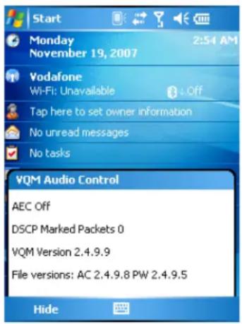
Figure B-2 VQM Audio Control Dialog Box
Voice Packet Prioritization
IP soft phones transmit voice packets in the same manner as any other application that sends data over the network. On a network with different types of traffic, voice packets are given the same priority as any other traffic, and therefore may be subject to delays.
WiFi Multi-media (WMM) is a solution to this problem. WMM is a specification that supports prioritizing traffic, and “higher-priority” packets can be given preferential treatment.
To make use of WMM, the devices that generate traffic must mark their packets as high or normal priority in a field in the IP packet called Differentiated Services Code-Point (DSCP). The wireless infrastructure, which must be configured to support WMM, gives a higher priority to packets that have been marked as high priority through DSCP marking by the devices that generate traffic.
VQM detects if there is an ongoing Voice over WiFi (VoWiFi) call, and if so, marks outgoing voice packets (Only outgoing voice packets can be marked. The incoming voice packets have already been through the network, so it makes no sense to mark them.) as high-priority using DSCP. This enables WMM-compatible wireless infrastructure to treat the voice packets preferentially. This results in fewer delays for voice packets, which in turn improves the call quality.
Acoustic Echo Cancellation
Acoustic Echo occurs during a voice call when the audio from the earpiece enters the microphone of the same device. This results in the person at the other end hearing back a delayed version of his/her own voice ("Echo"). Needless to say, "Echo" is not desirable, and needs to be suppressed. This is the functionality performed by the Acoustic Echo Canceller (AEC). There are two approaches to suppressing the Echo:
- Turn the Acoustic Echo Canceller (AEC) on permanently. This approach is not very efficient because the device consumes more power when the AEC is on.
- Turn the Acoustic Echo Canceller (AEC) on only when there is an ongoing call.
VQM follows the second of the two approaches mentioned above.
VQM automatically turns on the Acoustic Echo Canceller (AEC) when the mobile device is in a VoWiFi call. When the call is terminated, VQM turns the AEC off. Note that the AEC is turned on for speakerphone and handset modes and does not get turned on for wired headset and Bluetooth headset modes. The AEC is not required for wired headset because the audio volume is quite low (because of the proximity of the earpiece to the ear), and therefore it is very unlikely for the audio from the earpiece to go in to the mouthpiece. Bluetooth headsets typically have an Echo Canceller built in. Turning the AEC on only while on a call saves battery power, compared to leaving the AEC turned on permanently.
The AEC is not turned on for Cellular calls because the WWAN phone application has a built-in echo canceller.
Limitations
• There is no VPN support in VQM.
• Only the Avaya softphone is supported.
Disabling VQM
To disable VQM perform a warm boot.
Glossary
A
API. An interface by means of which one software component communicates with or controls another. Usually used to refer to services provided by one software component to another, usually via software interrupts or function calls
Aperture. The opening in an optical system defined by a lens or baffle that establishes the field of view.
Application Programming Interface. See API.
ANSI Terminal. A display terminal that follows commands in the ANSI standard terminal language. For example, it uses escape sequences to control the cursor, clear the screen and set colors. Communications programs support the ANSI terminal mode and often default to this terminal emulation for dial-up connections to online services.
ASCII. American Standard Code for Information Interchange. A 7 bit-plus-parity code representing 128 letters, numerals, punctuation marks and control characters. It is a standard data transmission code in the U.S.
Autodiscrimination. The ability of an interface controller to determine the code type of a scanned bar code. After this determination is made, the information content is decoded.
B
Bar. The dark element in a printed bar code symbol.
Bar Code. A pattern of variable-width bars and spaces which represents numeric or alphanumeric data in machine-readable form. The general format of a bar code symbol consists of a leading margin, start character, data or message character, check character (if any), stop character, and trailing margin. Within this framework, each recognizable symbology uses its own unique format. See Symbology.
Bar Code Density. The number of characters represented per unit of measurement (e.g., characters per inch).
Bar Height. The dimension of a bar measured perpendicular to the bar width.
Bar Width. Thickness of a bar measured from the edge closest to the symbol start character to the trailing edge of the same bar.
BIOS. Basic Input Output System. A collection of ROM-based code with a standard API used to interface with standard PC hardware.
Bit. Binary digit. One bit is the basic unit of binary information. Generally, eight consecutive bits compose one byte of data. The pattern of 0 and 1 values within the byte determines its meaning.
Bits per Second (bps). Bits transmitted or received.
BOOTP. A protocol for remote booting of diskless devices. Assigns an IP address to a machine and may specify a boot file. The client sends a bootp request as a broadcast to the bootp server port (67) and the bootp server responds using the bootp client port (68). The bootp server must have a table of all devices, associated MAC addresses and IP addresses.
boot or boot-up
The process a computer goes through when it starts. During boot-up, the computer can run self-diagnostic tests and configure hardware and software.
bps. See Bits Per Second.
Byte. On an addressable boundary, eight adjacent binary digits (0 and 1) combined in a pattern to represent a specific character or numeric value. Bits are numbered from the right, 0 through 7, with bit 0 the low-order bit. One byte in memory is used to store one ASCII character.
C
CDMA. Code Division Multiple Access (CDMA) is a form of multiplexing and a method of multiple access that does not divide up the channel by time (as in TDMA), or frequency (as in FDMA), but instead encodes data with a special code associated with each channel and uses the constructive interference properties of the special codes to perform the multiplexing.
CDRH. Center for Devices and Radiological Health. A federal agency responsible for regulating laser product safety. This agency specifies various laser operation classes based on power output during operation.
CDRH Class 1. This is the lowest power CDRH laser classification. This class is considered intrinsically safe, even if all laser output were directed into the eye's pupil. There are no special operating procedures for this class.
CDRH Class 2. No additional software mechanisms are needed to conform to this limit. Laser operation in this class poses no danger for unintentional direct human exposure.
Character. A pattern of bars and spaces which either directly represents data or indicates a control function, such as a number, letter, punctuation mark, or communications control contained in a message.
Character Set. Those characters available for encoding in a particular bar code symbology.
Check Digit. A digit used to verify a correct symbol decode. The scanner inserts the decoded data into an arithmetic formula and checks that the resulting number matches the encoded check digit. Check digits are required for UPC but are optional for other symbologies. Using check digits decreases the chance of substitution errors when a symbol is decoded.
Codabar. A discrete self-checking code with a character set consisting of digits 0 to 9 and six additional characters: (“-”, “\$”, “:”, “/”, “,” and “+”).
Code 128. A high density symbology which allows the controller to encode all 128 ASCII characters without adding extra symbol elements.
Code 3 of 9 (Code 39). A versatile and widely used alphanumeric bar code symbology with a set of 43 character types, including all uppercase letters, numerals from 0 to 9 and 7 special characters (“-”, “.”, “/”, “+”, “%”, “\$” and space). The code name is derived from the fact that 3 of 9 elements representing a character are wide, while the remaining 6 are narrow.
Code 93. An industrial symbology compatible with Code 39 but offering a full character ASCII set and a higher coding density than Code 39.
Code Length. Number of data characters in a bar code between the start and stop characters, not including those characters.
Cold Boot. A cold boot restarts the mobile computer and erases all user stored records and entries.
COM port. Communication port; ports are identified by number, e.g., COM1, COM2.
Continuous Code. A bar code or symbol in which all spaces within the symbol are parts of characters. There are no intercharacter gaps in a continuous code. The absence of gaps allows for greater information density.
Cradle. A cradle is used for charging the terminal battery and for communicating with a host computer, and provides a storage place for the terminal when not in use.
D
Data Communications Equipment (DCE). A device (such as a modem) which is designed to attach directly to a DTE (Data Terminal Equipment) device.
DCE. See Data Communications Equipment.
DCP. See Device Configuration Package.
Dead Zone. An area within a scanner's field of view, in which specular reflection may prevent a successful decode.
Decode. To recognize a bar code symbology (e.g., UPC/EAN) and then analyze the content of the specific bar code scanned.
Decode Algorithm. A decoding scheme that converts pulse widths into data representation of the letters or numbers encoded within a bar code symbol.
Decryption. Decryption is the decoding and unscrambling of received encrypted data. Also see, Encryption and Key.
Depth of Field. The range between minimum and maximum distances at which a scanner can read a symbol with a certain minimum element width.
Device Configuration Package. The Symbol Device Configuration Package provides the Product Reference Guide (PRG), flash partitions, Terminal Configuration Manager (TCM) and the associated TCM scripts. With this package hex images that represent flash partitions can be created and downloaded to the mobile computer.
Discrete Code. A bar code or symbol in which the spaces between characters (intercharacter gaps) are not part of the code.
Discrete 2 of 5. A binary bar code symbology representing each character by a group of five bars, two of which are wide. The location of wide bars in the group determines which character is encoded; spaces are insignificant. Only numeric characters (0 to 9) and START/STOP characters may be encoded.
DRAM. Dynamic random access memory.
DTE. See Data Terminal Equipment.
E
EAN. European Article Number. This European/International version of the UPC provides its own coding format and symbology standards. Element dimensions are specified metrically. EAN is used primarily in retail.
Element. Generic term for a bar or space.
Encoded Area. Total linear dimension occupied by all characters of a code pattern, including start/stop characters and data.
ENQ (RS-232). ENQ software handshaking is also supported for the data sent to the host.
ESD. Electro-Static Discharge
EvDO, 1xEV-DO. A wireless radio broadband data standard adopted by many CDMA mobile phone service providers. It is standardized by 3GPP2, as part of the CDMA2000 family of standards.
F
File Transfer Protocol (FTP). A TCP/IP application protocol governing file transfer via network or telephone lines. See TCP/IP.
Flash Disk. An additional megabyte of non-volatile memory for storing application and configuration files.
Flash Memory
Flash memory is nonvolatile, semi-permanent storage that can be electronically erased in the circuit and reprogrammed. Series 9000 mobile computers use Flash memory to store the operating system (ROM-DOS), the terminal emulators, and the Citrix ICA Client for DOS.
FTP
See File Transfer Protocol.
H
Hard Reset. See Cold Boot.
Hz. Hertz; A unit of frequency equal to one cycle per second.
Host Computer. A computer that serves other terminals in a network, providing such services as computation, database access, supervisory programs and network control.
High-Speed Downlink Packet Access (HSDPA). A 3G (third generation) mobile telephony communications protocol in the High-Speed Packet Access (HSPA) family, which allows networks based on Universal Mobile Telecommunications System (UMTS) to have higher data transfer speeds and capacity.
|
IDE. Intelligent drive electronics. Refers to the solid-state hard drive type.
IEC. International Electrotechnical Commission. This international agency regulates laser safety by specifying various laser operation classes based on power output during operation.
IEC (825) Class 1. This is the lowest power IEC laser classification. Conformity is ensured through a software restriction of 120 seconds of laser operation within any 1000 second window and an automatic laser shutdown if the scanner's oscillating mirror fails.
IEEE Address
See MAC Address.
Input/Output Ports. I/O ports are primarily dedicated to passing information into or out of the terminal's memory. Series 9000 mobile computers include Serial and USB ports.
Interleaved 2 of 5. A binary bar code symbology representing character pairs in groups of five bars and five interleaved spaces. Interleaving provides for greater information density. The location of wide elements (bar/spaces) within each group determines which characters are encoded. This continuous code type uses no intercharacter spaces. Only numeric (0 to 9) and START/STOP characters may be encoded.
Intercharacter Gap. The space between two adjacent bar code characters in a discrete code.
Interleaved Bar Code. A bar code in which characters are paired together, using bars to represent the first character and the intervening spaces to represent the second.
Internet Protocol Address. See IP.
IOCTL. Input/Output Control.
I/O Ports. interface The connection between two devices, defined by common physical characteristics, signal characteristics, and signal meanings. Types of interfaces include RS-232 and PCMCIA.
IP. Internet Protocol. The IP part of the TCP/IP communications protocol. IP implements the network layer (layer 3) of the protocol, which contains a network address and is used to route a message to a different network or subnetwork. IP
accepts "packets" from the layer 4 transport protocol (TCP or UDP), adds its own header to it and delivers a "datagram" to the layer 2 data link protocol. It may also break the packet into fragments to support the maximum transmission unit (MTU) of the network.
IP Address. (Internet Protocol address) The address of a computer attached to an IP network. Every client and server station must have a unique IP address. A 32-bit address used by a computer on a IP network. Client workstations have either a permanent address or one that is dynamically assigned to them each session. IP addresses are written as four sets of numbers separated by periods; for example, 204.171.64.2.
IPX/SPX. Internet Package Exchange/Sequential Packet Exchange. A communications protocol for Novell. IPX is Novell's Layer 3 protocol, similar to XNS and IP, and used in NetWare networks. SPX is Novell's version of the Xerox SPP protocol.
IS-95. Interim Standard 95. The EIA/TIA standard that governs the operation of CDMA cellular service. Versions include IS-95A and IS-95B. See CDMA.
K
Key. A key is the specific code used by the algorithm to encrypt or decrypt the data. Also see, Encryption and Decrypting.
L
LASER. Light Amplification by Stimulated Emission of Radiation. The laser is an intense light source. Light from a laser is all the same frequency, unlike the output of an incandescent bulb. Laser light is typically coherent and has a high energy density.
Laser Diode. A gallium-arsenide semiconductor type of laser connected to a power source to generate a laser beam. This laser type is a compact source of coherent light.
laser scanner. A type of bar code reader that uses a beam of laser light.
LCD. See Liquid Crystal Display.
LED Indicator. A semiconductor diode (LED - Light Emitting Diode) used as an indicator, often in digital displays. The semiconductor uses applied voltage to produce light of a certain frequency determined by the semiconductor's particular chemical composition.
Light Emitting Diode. See LED.
Liquid Crystal Display (LCD). A display that uses liquid crystal sealed between two glass plates. The crystals are excited by precise electrical charges, causing them to reflect light outside according to their bias. They use little electricity and react relatively quickly. They require external light to reflect their information to the user.
M
MC. Mobile Computer.
MDN. Mobile Directory Number. The directory listing telephone number that is dialed (generally using POTS) to reach a mobile unit. The MDN is usually associated with a MIN in a cellular telephone -- in the US and Canada, the MDN and MIN are the same value for voice cellular users. International roaming considerations often result in the MDN being different from the MIN.
MIL. 1 mil = 1 thousandth of an inch.
MIN. Mobile Identification Number. The unique account number associated with a cellular device. It is broadcast by the cellular device when accessing the cellular system.
Misread (Misdecode). A condition which occurs when the data output of a reader or interface controller does not agree with the data encoded within a bar code symbol.
Mobile Computer. In this text, mobile computer refers to the MC75. It can be set up to run as a stand-alone device, or it can be set up to communicate with a network, using wireless radio technology.
N
Nominal. The exact (or ideal) intended value for a specified parameter. Tolerances are specified as positive and negative deviations from this value.
Nominal Size. Standard size for a bar code symbol. Most UPC/EAN codes are used over a range of magnifications (e.g., from 0.80 to 2.00 of nominal).
NVM. Non-Volatile Memory.
O
ODI. See Open Data-Link Interface.
Open Data-Link Interface (ODI). Novell's driver specification for an interface between network hardware and higher-level protocols. It supports multiple protocols on a single NIC (Network Interface Controller). It is capable of understanding and translating any network information or request sent by any other ODI-compatible protocol into something a NetWare client can understand and process.
Open System Authentication. Open System authentication is a null authentication algorithm.
P
PAN. Personal area network. Using Bluetooth wireless technology, PANs enable devices to communicate wirelessly. Generally, a wireless PAN consists of a dynamic group of less than 255 devices that communicate within about a 33-foot range. Only devices within this limited area typically participate in the network.
Parameter
A variable that can have different values assigned to it.
PC Card. A plug-in expansion card for laptop computers and other devices, also called a PCMCIA card. PC Cards are 85.6mm long x 54 mm wide, and have a 68 pin connector. There are several different kinds:
Type I; 3.3 mm high; use - RAM or Flash RAM
Type II; 5 mm high; use - modems, LAN adaptors
Type III; 10.5 high; use - Hard Disks
PCMCIA. Personal Computer Memory Card Interface Association. See PC Card.
Percent Decode. The average probability that a single scan of a bar code would result in a successful decode. In a well-designed bar code scanning system, that probability should approach near 100%.
PING. (Packet Internet Groper) An Internet utility used to determine whether a particular IP address is online. It is used to test and debug a network by sending out a packet and waiting for a response.
Print Contrast Signal (PCS). Measurement of the contrast (brightness difference) between the bars and spaces of a symbol. A minimum PCS value is needed for a bar code symbol to be scannable. PCS = (RL - RD) / RL, where RL is the reflectance factor of the background and RD the reflectance factor of the dark bars.
Programming Mode. The state in which a scanner is configured for parameter values. See Scanning Mode.
Q
Quiet Zone. A clear space, containing no dark marks, which precedes the start character of a bar code symbol and follows the stop character.
QWERTY. A standard keyboard commonly used on North American and some European PC keyboards. "QWERTY" refers to the arrangement of keys on the left side of the third row of keys.
R
RAM. Random Access Memory. Data in RAM can be accessed in random order, and quickly written and read.
Reflectance. Amount of light returned from an illuminated surface.
Resolution. The narrowest element dimension which is distinguished by a particular reading device or printed with a particular device or method.
RF. Radio Frequency.
ROM. Read-Only Memory. Data stored in ROM cannot be changed or removed.
Router. A device that connects networks and supports the required protocols for packet filtering. Routers are typically used to extend the range of cabling and to organize the topology of a network into subnets. See Subnet.
RS-232. An Electronic Industries Association (EIA) standard that defines the connector, connector pins, and signals used to transfer data serially from one device to another.
s
Scan Area. Area intended to contain a symbol.
Scanner. An electronic device used to scan bar code symbols and produce a digitized pattern that corresponds to the bars and spaces of the symbol. Its three main components are: 1) Light source (laser or photoelectric cell) - illuminates a bar code,; 2) Photodetector - registers the difference in reflected light (more light reflected from spaces); 3) Signal conditioning circuit - transforms optical detector output into a digitized bar pattern.
Scanning Mode. The scanner is energized, programmed and ready to read a bar code.
Scanning Sequence. A method of programming or configuring parameters for a bar code reading system by scanning bar code menus.
SDK. Software Development Kit
Self-Checking Code. A symbology that uses a checking algorithm to detect encoding errors within the characters of a bar code symbol.
Shared Key. Shared Key authentication is an algorithm where both the AP and the MU share an authentication key.
SHIP. Symbol Host Interface Program.
SID. System Identification code. An identifier issued by the FCC for each market. It is also broadcast by the cellular carriers to allow cellular devices to distinguish between the home and roaming service.
SMDK. Symbol Mobility Developer's Kit.
Soft Reset. See Warm Boot.
Space. The lighter element of a bar code formed by the background between bars.
Specular Reflection. The mirror-like direct reflection of light from a surface, which can cause difficulty decoding a bar code.
Start/Stop Character. A pattern of bars and spaces that provides the scanner with start and stop reading instructions and scanning direction. The start and stop characters are normally to the left and right margins of a horizontal code.
STEP. Symbol Terminal Enabler Program.
Subnet. A subset of nodes on a network that are serviced by the same router. See Router.
Subnet Mask. A 32-bit number used to separate the network and host sections of an IP address. A custom subnet mask subdivides an IP network into smaller subsections. The mask is a binary pattern that is matched up with the IP address to turn part of the host ID address field into a field for subnets. Default is often 255.255.255.0.
Substrate. A foundation material on which a substance or image is placed.
SVTP. Symbol Virtual Terminal Program.
Symbol. A scannable unit that encodes data within the conventions of a certain symbology, usually including start/stop characters, quiet zones, data characters and check characters.
Symbol Aspect Ratio. The ratio of symbol height to symbol width.
Symbol Height. The distance between the outside edges of the quiet zones of the first row and the last row.
Symbol Length. Length of symbol measured from the beginning of the quiet zone (margin) adjacent to the start character to the end of the quiet zone (margin) adjacent to a stop character.
Symbology. The structural rules and conventions for representing data within a particular bar code type (e.g. UPC/EAN, Code 39, PDF417, etc.).
T
TCP/IP. (Transmission Control Protocol/Internet Protocol) A communications protocol used to internetwork dissimilar systems. This standard is the protocol of the Internet and has become the global standard for communications. TCP provides transport functions, which ensures that the total amount of bytes sent is received correctly at the other end. UDP is an alternate transport that does not guarantee delivery. It is widely used for real-time voice and video transmissions where erroneous packets are not retransmitted. IP provides the routing mechanism. TCP/IP is a routable protocol, which means that all messages contain not only the address of the destination station, but the address of a destination network. This allows TCP/IP messages to be sent to multiple networks within an organization or around the world, hence its use in the worldwide Internet. Every client and server in a TCP/IP network requires an IP address, which is either permanently assigned or dynamically assigned at startup.
Telnet. A terminal emulation protocol commonly used on the Internet and TCP/IP-based networks. It allows a user at a terminal or computer to log onto a remote device and run a program.
Terminal. See Mobile Computer.
Terminal Emulation. A “terminal emulation” emulates a character-based mainframe session on a remote non-mainframe terminal, including all display features, commands and function keys. The VC5000 Series supports Terminal Emulations in 3270, 5250 and VT220.
Terminate and Stay Resident (TSR). A program under DOS that ends its foreground execution to remain resident in memory to service hardware/software interrupts, providing background operation. It remains in memory and may provide services on behalf of other DOS programs.
TFTP. (Trivial File Transfer Protocol) A version of the TCP/IP FTP (File Transfer Protocol) protocol that has no directory or password capability. It is the protocol used for upgrading firmware, downloading software and remote booting of diskless devices.
Tolerance. Allowable deviation from the nominal bar or space width.
Transmission Control Protocol/Internet Protocol. See TCP/IP.
Trivial File Transfer Protocol. See TFTP.
TSR. See Terminate and Stay Resident.
U
UDP. User Datagram Protocol. A protocol within the IP protocol suite that is used in place of TCP when a reliable delivery is not required. For example, UDP is used for real-time audio and video traffic where lost packets are simply ignored, because there is no time to retransmit. If UDP is used and a reliable delivery is required, packet sequence checking and error notification must be written into the applications.
UPC. Universal Product Code. A relatively complex numeric symbology. Each character consists of two bars and two spaces, each of which is any of four widths. The standard symbology for retail food packages in the United States.
V
Visible Laser Diode (VLD). A solid state device which produces visible laser light.
W
Warm Boot. A warm boot restarts the mobile computer by closing all running programs. All data that is not saved to flash memory is lost.
Glossary - 12 MC75 User Guide
Index
Numerics
1-D bar codes 2-29
2-D bar codes 2-29
A
accessories 1-3
auto charge cable 1-3
cables 1-3,6-19
charge cable 1-3
communication/charge cables battery charging 6-19
LED indicators 6-20
DEX cable 1-3
EMDK 1-4
four slot battery charger 1-3, 6-1, 6-9
four slot charge only cradle 6-5
four slot Ethernet cradle 1-3, 6-1, 6-4
headset 1-4,6-1,6-18
holster 1-4
magnetic stripe reader 1-3, 6-11, 6-18
microSD card 1-9
modem cable 1-3
modem dongle 1-3
modem inverter cable 1-3
MSR 1-3,6-11
installation 6-11
magnetic stripe reading 6-11
O'Neil printer cable 1-3
rigid holster 6-1
serial charge cable 1-3
SIM card 1-4
single slot USB cradle 1-3
single slot USB serial cradle .....6-1, 6-2
spare battery 1-3
specifications A-6
stylus 1-4
USB charge cable 1-3
USB charger cable 1-3
vehicle cradle 1-3, 6-1, 6-6
wall mounting kit, cradle 1-4
Zebra printer cable 1-3
zebra printer cable 1-3
Acoustic Echo Cancellation B-2
action button 2-27
ActiveSync 2-5 icon 2-4
adaptive frequency hopping 4-1
adjusting handstrap 1-10
adjusting volume 2-10
AFH 4-1
AirBEAM 2-5
alpha-numeric keypad 2-19 key descriptions 2-20
answering a call 5-7
assisted GPS 3-2
auto charge cable 1-3, 6-19
AZERTY 2-19
B
backup battery charging 1-7
bar codes one dimensional 2-29 two dimensional 2-29
battery charging 1-7, 6-2, 6-4, 6-5, 6-6, 6-9
check status 1-8
installing 1-6
removing 1-11
battery charger charging 6-9
charging indicators 6-10
battery chargers
communication/charge cables 6-19
LED indicators 6-20
four slot 6-9
battery charging
communication/charge cables 6-19
using four slot battery charger 6-9
using four slot Ethernet cradle .....6-4, 6-5
using single slot USB serial cradle 6-2
using vehicle cradle 6-6
battery icon
battery reserve options
blue key .....2-16, 2-20
Bluetooth
adaptive frequency hopping 4-1
bonding 4-20
deleting bonded device 4-22
icon 2-4
security 4-2
turning off 4-3
turning on 4-3
bluetooth
discovering devices 4-6
icon 2-4
turning on and off 4-3
Bluetooth headset
bonding
Bluetooth 4-20
boot
cold 2-14,4-4
warm 2-14, 4-4
BTExplorer
bullets
buttons
action 2-27
function 2-27
power 1-8,2-14,2-27,2-28
scan 2-27
up and down 2-27
C
cables 1-3,6-19
auto charge cable 1-3
charge only 1-3
connecting 6-19
DEX cable 1-3
modem 1-3
modem dongle 1-3
modem inverter 1-3
serial charge 1-3
USB charge 1-3
USB charger 1-3
calculator 2-5
calendar 2-4
calibrating the screen 1-8
call history 5-10, 5-15
camera....xii
charge only cable 1-3
charging 2-13
spare batteries 1-8, 6-3, 6-7, 6-9
using four slot battery charger 6-9
using four slot Ethernet cradle 6-4, 6-5
using single slot USB serial cradle 6-2
using vehicle cradle 6-6
charging indicators 6-20
four slot battery charger 6-10
four slot Ethernet cradle 6-4, 6-5
single slot USB serial cradle 6-3
vehicle cradle 6-8
charging temperature 1-8,6-3
cleaning 7-1
clock & alarms 2-7
cold boot 2-14, 4-4
command bar 2-4
icons 2-4
communication 6-19
communication/charge cables 6-19
battery charging 6-19
LED indicators 6-20
conference call 5-20, 5-22
configuration xii, 1-4
connectivity icon 2-2
Contacts 2-4
contacts 2-4
contacts application 5-5
conventions
notational....xv
cradles
four slot battery charger 6-1, 6-9
four slot charge only cradle 6-5
four slot Ethernet 1-3, 6-1, 6-4, 6-5
single slot USB serial 6-1, 6-2
vehicle 1-3,6-1,6-6
D
data capture ..... xii
imager operational modes
decode mode 2-29
image capture mode 2-29
pick list mode 2-29
imaging 2-29
linear scanning 2-29
one dimensional bar codes 2-29
scan angle 2-30
scan button 2-27
scan range 2-30
scanning 2-30, 2-31, 2-32
two dimensional bar codes 2-29
deleting Bluetooth bond 4-22
DEX cable 1-3, 6-19
digital camera 2-30
display xii
dual line SIM 5-26
E
emergency calls....2-15, 5-7
end key 2-17, 2-20
entering data 2-28
enterprise mobility developer kit 1-4
ESD 1-9
Ethernet cradle 1-3, 6-1, 6-4
EVDO ..... xii
Evolution Data-Optimized 5-1
F
fabric holster 1-4
file explorer 2-5
flash card 6-18
four slot battery charger 1-3, 6-1, 6-9
charging 6-9
charging indicators 6-10
four slot charge only cradle 6-5
four slot Ethernet cradle 6-4
charging 6-4, 6-5
charging indicators 6-4, 6-5
four slot spare battery charger
setup 6-9
shim installation 6-9
function buttons 2-27
G
Get Good 2-5
global positioning system 3-1
Good Mobile Messaging 2-5
GPS....xii, 3-1
H
handset B-2
handset mode 5-3
handstrap adjusting 1-10
hard reset 2-14, 4-4
headset 1-4,5-3,5-4,6-1,6-18
headset mode 5-3
High-Speed Downlink Packet Access 5-1
holster 1-4
HSDPA ..... xii
|
icons
ActiveSync 2-4
battery 2-3, 2-10
Bluetooth 2-4
bluetooth 2-4
connectivity 2-2
phone 2-3
speaker 2-3, 2-10
status 2-2
task tray 2-4
time and appointment 2-3
wireless status 2-4
imager. See data capture, imaging, imagersample
imaging 2-29, 2-30
indicators 2-13
radio status 2-13
information, service ..... xvi
installing battery 1-6
Internet Explorer Mobile 2-4
internet sharing 2-5
IrDA 2-9
K
key descriptions
alpha-numeric keypad 2-20
numeric keypad 2-16
keypads ..... xii
input modes ..... 2-18, 2-22, 2-23, 2-24
key descriptions 2-16, 2-20
numeric 2-16
phone 5-1
QWERTY 2-19
special character key 2-26
types 2-16
L
laser scanning
See data capture 2-29
LEDs
battery status 2-13
charging ..... 2-13, 6-3, 6-4, 6-5, 6-8, 6-10, 6-20
indicators 2-13
radio status 2-13
scan and decode ..... 2-13, 2-31, 2-32, 2-33
lithium-ion battery 1-2
locking MC75 2-15
M
magnetic stripe reader ..... 1-3, 6-11, 6-18
installation 6-11
magnetic stripe reading 6-11
main battery
charging 1-4, 1-7
installing 1-4
maintenance 7-1
Media Player 2-6
memory .....xii
memory card 1-9
messaging 2-5
mircoSD 1-9
MMC 6-18
modem cable 1-3, 6-19
modem inverter cable 1-3
MSP Agent 2-5
MSR 1-3,6-11,6-18
installation 6-11
magnetic stripe reading 6-11
muting a call 5-9
N
navigation bar icons 2-2
notational conventions....xv
notes 2-6
notes application 5-10
notification icons 2-2
numeric keypad 2-16
input modes 2-18
key descriptions 2-16
0
O'Neil printer cable 6-19
operating environment....A-1
operating system ....xii
orange key .....2-16, 2-20
P
phone 2-5
answering a call 5-7
call history 5-15
call swapping .....5-19, 5-20
conference call 5-20, 5-22
contacts 5-5
keypad 5-1
muting a call 5-9
speed dial adding entry 5-11
calling 5-6
deleting entry 5-14
editing entry 5-13
taking notes 5-10
text messaging 5-23
three-way call 5-20, 5-22
turning on and off 5-2
using keypad 5-5
phone icon 2-3
pictures 2-6
power button 1-8, 2-14, 2-27, 2-28
Q
QWERTY keypad input modes ..... 2-22, 2-23, 2-24
QWERTZ 2-19
R
radios....xii
rapid deployment 2-6
removing main battery 1-11
reset 2-14
hard 2-14,4-4
soft 2-14,4-4
resume 4-4
rigid holster 1-4, 6-1
RS232 charge cable 6-19
S
scan button 2-27
scan key 2-17
scan/decode 2-13
scanning button 2-27
imaging 2-29
See data capture 2-29
screen calibration 1-8
screen protector 1-10
SDK See EMDK 1-4
search 2-6
security Bluetooth 4-2
serial charge cable 1-3, 6-19
service information ..... xvi
settings 2-7 about 2-7
backlight 2-7
beam 2-9
buttons 2-7
certificates 2-7
connections 2-9
customer feedback 2-8
encryption 2-8
error reporting 2-8
external GPS 2-8
GPS Setup 2-8
input 2-7
keylight 2-8
lock 2-7
memory 2-8
menus 2-7
owner information 2-7
phone 2-7
power 2-8
regional settings 2-8
remove programs 2-8
screen 2-8
sounds & notifications 2-7
system info 2-8
today 2-7
USB to PC 2-9
Wi-Fi 2-9
wireless manager 2-9
shim installation 6-9
SIM card
accessories 1-4
install 1-4
SIM Toolkit 2-6
single slot USB cradle 1-3
single slot USB serial cradle 6-2
charging 6-2
charging indicators 6-3
SiRF III....xii, 3-1
smart dialing 5-8
soft reset 2-14, 4-4
spare battery 1-3
charging 1-8,6-3,6-7,6-9
spare battery charger
setup 6-9
speaker icon 2-3, 2-10
speaker mode 5-3
special character key 2-26
speed dial 5-6, 5-11
starting the EDA 1-4, 1-8
status icon 2-2
battery 2-3, 2-10
connectivity 2-2
phone 2-3
speaker 2-3, 2-10
time and appointment 2-3
strap 1-2
stylus 1-2, 1-4, 2-28
subscriber identification module 1-4
suspend 1-11, 2-27, 4-4
T
talk key 2-17, 2-20
task tray icons 2-4
tasks 2-6
technical specifications A-1
accessories A-6
temperature A-2
charging 1-8,6-3
temperature notification 2-12
three-way call 5-20, 5-22
time and appointment icon 2-3
Time To First Fix 3-3
Today screen 2-1
troubleshooting 7-5
U
unlock 2-15
unpacking 1-2
up and down button 2-27
USB charge cable 1-3
USB charger 1-3
USB client charge cable 6-19
using Bluetooth headset 5-4
using stylus 2-28
using wired headset 5-3
V
vehicle cradle 1-3, 6-1, 6-6
charging indicators 6-8
videos 2-6
Voice Quality Manager B-1
VQM B-1
disabling B-4
enabling B-1
W
wakeup conditions 2-14
waking EDA 2-14
wall mounting kit, cradle 1-4
warm boot 2-14, 4-4
Windows Live 2-6
Windows Live Messenger 2-5
wired headset 5-3
Wireless 1-13,5-2
Wireless Manager 1-13, 5-2
wireless manager 2-9
wireless status 2-4
WLAN 802.11a/b/g ..... xii
Index - 6 MC75 User Guide
WPAN Bluetooth ..... xii
Z
Zebra printer cable 6-19

MOTOROLA
Motorola, Inc.
One Motorola Plaza
Holtsville, New York 11742, USA
1-800-927-9626
http://www.motorola.com/enterprisemobility
MOTOROLA and the Stylized M Logo and Symbol and the Symbol logo are registered in the U.S. Patent and Trademark Office.
All other product or service names are the property of their registered owners.
© Motorola, Inc. 2008

- MC75 Enterprise Digital Assistant
- User Guide
- MC75 Enterprise Digital Assistant User Guide
- Patents
- Revision History
- Table of Contents
- About This Guide
- Chapter 1: Getting Started
- Chapter 2: Using the MC75
- Chapter 3: Using GPS Navigation
- Chapter 4: Using Bluetooth
- Chapter 5: Using the Phone
- Chapter 6: Accessories
- Chapter 7: Maintenance & Troubleshooting
- Appendix A: Technical Specifications
- Appendix B: Voice Quality Manager
- Glossary
- Index
- Introduction
- Documentation Set
- Configurations
- Software Versions
- AKU Version
- OEM Version
- BTExplorer Software
- Fusion Software
- Phone Software
- Chapter Descriptions
- Notational Conventions
- Related Documents
- Service Information
- Chapter 1 Getting Started
- Unpacking
- Accessories
- Getting Started
- Installing the SIM Card
- Installing the Main Battery
- Charging the Battery
- Charging the Main Battery and Memory Backup Battery
- Charging Spare Batteries
- Charging Temperature
- Powering On the MC75
- Calibrating the Screen
- Checking Battery Status
- Micro Secure Digital (microSD) Card
- Adjusting the Handstrap
- Removing the Screen Protector
- Replacing the Main Battery
- Battery Management
- Changing the Power Settings
- Changing the Backlight Settings
- Changing the Keypad Backlight Settings
- Turning Off the Radios
- Chapter 2 Using the MC75
- Today Screen
- Status Icons
- Programs
- Settings
- Adjusting Volume
- Battery Status Indications
- Battery Reserve Options
- Main Battery Temperature Notifications
- LED Indicators
- Resetting the MC75
- Performing a Warm Boot
- Performing a Cold Boot
- Waking the MC75
- Locking the MC75
- Keypads
- Numeric Keypad Configuration
- Alpha-numeric Keypad Configurations
- Special Character Key
- Function Buttons
- Stylus
- Entering Data
- Data Capture
- Linear Scanning
- Imaging
- Operational Modes
- Digital Camera
- Scanning Considerations
- Imager Scanning
- Digital Camera Scanning
- Taking Photos
- Recording Video
- Viewing Photos and Videos
- Using IrDA
- Infrared Connection
- Exchanging Files using IR Connection
- Chapter 3 Using GPS Navigation
- WARNING!
- Software Installation
- MC75 GPS Setup
- Operation
- GPS Maps on microSD Cards
- Answering a Phone Call While Using GPS
- Losing the GPS Signal While in a Vehicle
- Assisted GPS
- Chapter 4 Using Bluetooth
- Adaptive Frequency Hopping
- Security
- Recommendations are:
- Turning the Bluetooth Radio Mode On and Off
- Disabling Bluetooth
- Enabling Bluetooth
- Bluetooth Power States
- Cold Boot
- Warm Boot
- Suspend
- Resume
- Modes
- Wizard Mode
- Explorer Mode
- Discovering Bluetooth Device(s)
- Available Services
- File Transfer Services
- Creating a New File or Folder
- Deleting a File
- Getting a File
- Copying a File
- Connecting to the Internet Using an Access Point
- Dial-Up Networking Services
- Object Exchange Push Services
- Sending a Contact
- Swapping Contacts
- Fetching a Contact
- Sending a Picture
- Headset Services
- Hands-free Services
- Serial Port Services
- ActiveSync Using Serial Port Services
- Personal Area Network Services
- IrMC Synchronization Services
- Bonding with Discovered Device(s)
- Deleting a Bonded Device
- Accepting a Bond
- Bluetooth Settings
- Device Info Tab
- Services Tab
- Dial-Up Networking Service
- File Transfer Service
- Hands-Free Audio Gateway Service
- Headset Audio Gateway Service
- IrMC Synchronization Service
- OBEX Object Push Service
- Personal Area Networking Service
- Serial Port Service
- Security Tab
- Discovery Tab
- Virtual COM Port Tab
- HID Tab
- Profiles Tab
- Chapter 5 Using the Phone
- Accessing the Phone Keypad
- Turning the Phone On and Off
- Audio Modes
- Using a Wired Headset
- Using a Bluetooth Headset
- Adjusting Audio Volume
- Making a Call
- Using the Phone
- Using Contacts
- Using Call History
- Making a Speed Dial Call
- Making an Emergency Call
- Answering a Call
- Incoming Call Features
- Smart Dialing
- Muting a Call
- Taking Notes
- Using Speed Dial
- Adding a Speed Dial Entry
- Editing a Speed Dial Entry
- Deleting a Speed Dial Entry
- Managing Call History
- Changing the Call History View
- Resetting the Recent Calls Counter
- Tap Menu.
- Select Call Timers...
- Deleting Call History Items by Call Date
- Deleting All Call History Items
- Viewing Call Status
- Using the Call History Menu
- Swapping Calls on an MC7506/96
- Swapping Calls on an MC7508/98
- Conference Calling on an MC7506/96
- Three-way Calling on an MC7508/98
- Text Messaging
- Viewing Text Messages
- Sending a Text Message
- Tap Menu > Send Text Message.
- Compose your message.
- Tap Send when you've finished the message.
- Using a Dual Line SIM
- Chapter 6 Accessories
- Single Slot USB/Serial Cradle
- Charging the MC75 Battery
- Charging the Spare Battery
- Battery Charging Indicators
- Four Slot Ethernet Cradle
- Charging
- Four Slot Charge Only Cradle
- VCD7X00 Vehicle Cradle
- Removing the MC75
- Four Slot Battery Charger
- MC75 Battery Shim Installation
- Spare Battery Charging
- Magnetic Stripe Reader (MSR)
- Attaching and Removing the MSR
- Using the MSR
- Debit Card Reader
- Installation
- Removal
- Credit Card Transactions
- Debit Card Transactions
- Keypad
- Display Messages
- Check the DCR Battery Level
- Headset
- Cables
- Battery Charging and Operating Power
- LED Charge Indications
- Chapter 7 Maintenance & Troubleshooting
- Maintaining the MC75
- Battery Safety Guidelines
- Cleaning
- Materials Required
- Cleaning the MC75
- Housing
- Display
- Scanner Exit Window
- Connector
- Cleaning Cradle Connectors
- Cleaning Frequency
- Troubleshooting
- Bluetooth Connection
- Vehicle Cradle
- Magnetic Stripe Reader
- Appendix A Technical Specifications
- MC75 Technical Specifications
- MC75
- MC75 Accessory Specifications
- Appendix B Voice Quality Manager
- Features
- Enabling VQM
- Changing Audio Modes
- Voice Packet Prioritization
- Acoustic Echo Cancellation
- Limitations
- Disabling VQM
- A
- Application Programming Interface. See API.
- B
- C
- D
- E
- F
- H
- |
- K
- L
- M
- N
- O
- P
- Q
- R
- s
- T
- Terminal. See Mobile Computer.
- U
- V
- W
- Numerics
- G
- 0
- Index - 6 MC75 User Guide
- Z
- MOTOROLA
Brand : ZEBRA
Model : MC75
Category : Barcode scanners