
PowerScan M8300 - Barcode scanners ZEBRA - Free user manual and instructions
Find the device manual for free PowerScan M8300 ZEBRA in PDF.


| Product Type | Industrial Cordless Laser Scanner with Display and Keypad |
| Brand | Zebra (formerly Psion Teklogix) |
| Model | PowerScan M8300 |
| Scanner Technology | Laser, Class 2 (CDRH 21 CFR 1040 and EN60825-1 compliant) |
| Radio Frequency | 433 MHz (EU) / 910 MHz (US) |
| Max Resolution | 0.13 mm (5 mils) |
| Typical Reading Range | Up to 55 cm (21.7 in) for 15 mil codes |
| Interface Options | RS-232, USB (Keyboard, COM, IBM), Wedge, Pen Emulation, RS-485 (Network) |
| Network Support | STAR-System multidrop network up to 512 readers and 16 base stations with auto-roaming |
| Battery Type | Rechargeable, replaceable battery pack (NiMH or Li-ion) |
| Battery Charging | Via BC-80X0 or C-8000 cradle (red LED = charging, green = full) |
| Display | Yes, with 3-button keypad (some models) |
| Indicators | Green/red LEDs, adjustable audible beeper (tone, intensity, length) |
| Special Features | Puzzle Solver technology, aim mode, co-moulded rubber, shock-absorbed optics |
| Decode Capability | All standard 1D codes including GS1 DataBar family |
| Configuration Methods | Bar code menus, Datalogic Aladdin software, serial commands from host |
| Compliance | FCC Part 15 Class B, CE (R&TTE 1999/5/EC), RoHS 2002/95/EC, WEEE 2002/96/EC, Laser Class 2 |
| Warranty | 12 months return-to-factory from date of shipment |
| Operating Temperature | Not specified; typical for industrial scanners 0°C to 40°C |
| Dimensions | Not specified; approximate 180 x 70 x 100 mm (estimated) |
| Weight | Not specified; approximately 250 g (estimated) |
| Included Accessories | Quick Reference Guide, BC-80X0/C-8000 cradle, antenna, mounting bases and hardware, bind-address label |
| Maintenance | Replace battery pack; clean with dry cloth; do not expose to high temperature |
| Safety | Laser class 2: avoid direct eye exposure; use only specified charger; do not incinerate batteries |
| Repairability | Only qualified personnel; return to factory for warranty repairs |
Frequently Asked Questions - PowerScan M8300 ZEBRA
User questions about PowerScan M8300 ZEBRA
0 question about this device. Answer the ones you know or ask your own.
Ask a new question about this device
Download the instructions for your Barcode scanners in PDF format for free! Find your manual PowerScan M8300 - ZEBRA and take your electronic device back in hand. On this page are published all the documents necessary for the use of your device. PowerScan M8300 by ZEBRA.
USER MANUAL PowerScan M8300 ZEBRA
April 22, 2008 Part No. 8100166.A
natural_image
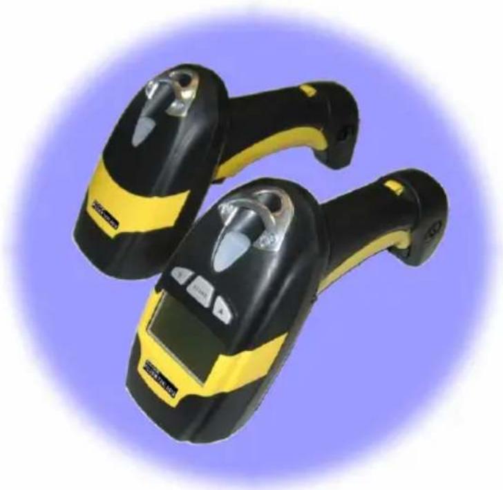
Two black and yellow barcode barcodes against a purple circular background (no text or symbols visible)Copyright © 2008 Psion Teklogix Inc. Mississauga, Ontario
All rights reserved. This document is an unpublished work and the information it contains is the property of Psion Teklogix, or its licensors, is issued in strict confidence, and may not be reproduced or copied, in whole or in part, except with written consent from Psion Teklogix. Furthermore, this document is not to be used as a basis for design, manufacture, or subcontract, or in any manner detrimental to the interests of Psion or its licensors. Psion ^® , Teklogix ^® , and all Psion Teklogix products and brand names are trademarks of Psion Teklogix and its affiliates.
Windows® and the Windows Logo are trademarks or registered trademarks of Microsoft Corporation in the United States and/or other countries.
All trademarks are the property of their respective holders.
Return-To-Factory Warranty
Psion Teklogix Inc. provides a return to factory warranty on this product for a period of twelve (12) months in accordance with the statement of Warranty and Product Support provided at:
www.psionteklogix.com/warranty
The warranty on Psion Teklogix manufactured equipment does not extend to any product that has been tampered with, altered, or repaired by any person other than an employee of an authorized Psion Teklogix service organization. See Psion Teklogix terms and conditions of sale for full details.

Important: Psion Teklogix warranties take effect on the date of shipment.
Support Services And Worldwide Offices
Psion Teklogix provides a complete range of product support services to its customers worldwide. These services include technical support and product repairs.
Technical Support
For technical support in North America:
Call Toll free: +1 800 387 8898 Option 3, or
Direct Dial: +1 905 813 9900 Ext. 1999 Option 3
For technical support in EMEA (Europe, Middle East and Africa), please contact the local office listed in the website below:
http://www.psionteklogix.com/EMEASupport
For technical support in Asia, please contact the local office listed in the website below:
http://www.psionteklogix.com
Technical Support for Mobile Computing Products is provided via email through the Psion Teklogix customer and partner extranets. To reach the website, go to www.psionteklogix.com, and click on the appropriate Teknet link on the home page. Then click on the “Login” button or the “Register” button, depending on whether you have previously registered for Teknet. Once you have logged in, search for the “Support Request Form”.
Product Repairs
For repair service in North America:
Call Toll free: +1 800 387 8898 Option 2, or
Direct Dial: +1 905 813 9900 Ext. 1999 Option 2
For repair service in EMEA (Europe, Middle East and Africa), please contact the local office listed in the website below:
http://www.psionteklogix.com/EMEASupport
For repair service in Asia, please contact the local office listed in the website below:
http://www.psionteklogix.com
Worldwide Offices
COMPANY HEADQUARTERS CANADIAN SERVICE CENTRE
Psion Teklogix Inc. Psion Teklogix Inc.
2100 Meadowvale Blvd. 7170 West Credit Ave., Unit #1
Mississauga, Ontario Mississauga, Ontario
Canada L5N 7J9 Canada L5N 7J9
Tel: +1 905 813 9900 Tel: +1 800 387 8898 Option 2 - or -
Direct: +1 905 813 9900 Ext. 1999, Option 2
INTERNATIONAL SUBSIDIARIES (see also www.psionteklogix.com/Subsidiaries)
Psion Teklogix S.A.
La Duranne, 135 Rue Rene Descartes
BP 421000
13591 Aix-En-Provence
Cedex 3; France
Tel: +33 4 42 90 88 09
Fax: +33 4 42 90 88 88
E-mail: tekeuro@psion.com
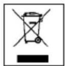
Waste Electrical and Electronic Equipment (WEEE) Directive 2002/96/EC
This Product, and its accessories, comply with the requirements of the Waste Electrical and Electronic Equipment (WEEE) Directive 2002/96/EC. If your end-of-life Psion Teklogix product or accessory carries a label as shown here, please contact your local country representative for details on how to arrange recycling. For a list of international subsidiaries, please go to:
www.psionteklogix.com/EnvironmentalCompliance
Restriction On Hazardous Substances (RoHS) Directive 2002/95/EC
What is RoHS?
The European Union has mandated that high environmental standards be met in the design and manufacture of electronic and electrical products sold in Europe, to reduce hazardous substances from entering the environment. The “Restriction on Hazardous Substances Directive (RoHS)” prescribes the maximum trace levels of lead, cadmium, mercury, hexavalent chromium, and flame retardants PBB and PBDE that may be contained in a product. Only products meeting these high environmental standards may be “placed on the market” in EU member states after July 1, 2006.

RoHS Logo
Although there is no legal requirement to mark RoHS-compliant products, Psion Teklogix Inc. indicates its compliance with the directive as follows:
The RoHS logo located either on the back of the product or underneath the battery in the battery compartment (or on a related accessory such as the charger or docking station) signifies that the product is RoHS-compliant as per the EU directive. Other than as noted below, a Psion Teklogix product that does not have an accompanying RoHS logo signifies that it was placed on the EU market prior to July 1, 2006, and is thereby exempt from the directive.

Note: Not all accessories or peripherals will have a RoHS logo due to physical space limitations or as a result of their exempt status.
Disclaimer
Every effort has been made to make this material complete, accurate, and up-to-date. In addition, changes are periodically added to the information herein; these changes will be incorporated into new editions of the publication.
Psion Teklogix Inc. reserves the right to make improvements and/or changes in the product(s) and/or the program(s) described in this document without notice, and shall not be responsible for any damages, including but not limited to consequential damages, caused by reliance on the material presented, including but not limited to typographical errors.
This device must be opened by qualified personnel only. The batteries must be removed before opening the device.
FCC COMPLIANCE
Modifications or changes to this equipment without the express written approval of Psion Teklogix could void the authority to use the equipment.
This device complies with PART 15 of the FCC Rules. Operation is subject to the following two conditions: (1) This device may not cause harmful interference, and (2) this device must accept any interference received, including interference which may cause undesired operation.
FCC ID U4F0015.
This equipment has been tested and found to comply with the limits for a Class B digital device, pursuant to Part 15 of the FCC Rules. These limits are designed to provide reasonable protection against harmful interference in a residential installation. This equipment generates, uses and can radiate radio frequency energy and, if not installed and used in accordance with the instructions, may cause harmful interference to radio communications. However, there is no guarantee that interference will not occur in a particular installation.
If this equipment does cause harmful interference to radio or television reception, which can be determined by turning the equipment off and on, the user is encouraged to try to correct the interference by one of the following measures:
- Reorient or relocate the receiving antenna.
- Increase the separation between the equipment and receiver.
- Connect the equipment into an outlet on a circuit different from that to which the receiver is connected.
- Consult the dealer or an experienced radio/TV technician for help.
Emissions Information For Canada
Contact the competent authority responsible for the management of radio frequency devices of your country to verify any possible restrictions or licenses required.
Refer to the web site http://europa.eu.int/comm/enterprise/rtte/spectr.htm for further information.

When used in a residential, commercial or light industrial environment the product and its approved UK and European peripherals fulfil all requirements for CE marking.
This equipment complies with the essential requirements of EU Directive 1999/5/EC (Declaration available: www.psionteklogix.com).
Cet équipement est conforme aux principales caractéristiques définies dans la Directive européenne RTTE 1999/5/CE. (Déclaration disponible sur le site: www.psionteklogix.com).
Die Geräte erfüllen die grundlegenden Anforderungen der RTTE-Richtlinie (1999/5/EG). (Den Wortlaut der Richtlinie finden Sie unter: www.psionteklogix.com).
Questa apparecchiatura è conforme ai requisiti essenziali della Direttiva Europea R&TTE 1999/5/CE. (Dichiarazione disponibile sul sito: www.psionteklogix.com).
Este equipo cumple los requisitos principales de la Directiva 1995/5/CE de la UE, “Equipos de Terminales de Radio y Telecomunicaciones”. (Declaración disponible en: www.psionteklogix.com).
Este equipamento cumpre os requisitos essenciais da Directiva 1999/5/CE do Parlamento Europeu e do Conselho (Directiva RTT). (Declaração disponível no endereço: www.psionteklogix.com).
Ο εξοπλισμός αυτός πληροί τις βασικές απαιτήσεις της κοινοτικής οδηγίας EU R&TTE 1999/5/EK. (Η δήλωση συμμόρφωσης διατίθεται στη διεύθυνση: www.psionteklogix.com)
Deze apparatuur voldoet aan de noodzakelijke vereisten van EU-richtlijn betreffende radioapparatuur en telecommunicatie-eindappa-ratuur 199/5/EG. (verklaring beschikbaar: www.psionteklogix.com).
Dette udstyr opfylder de Væsentlige krav i EU's direktiv 1999/5/EC om Radio- og teleterminaludstyr. (Erklæring findes på: www.psionteklogix.com).
Dette utstyret er i overensstemmelse med hovedkravene i R&TTE-direktivet (1999/5/EC) fra EU. (Erklæring finnes på: www.psionteklogix.com).
Utrustningen uppfyller kraven för EU-direktivet 1999/5/EC om ansluten teleutrustning och ömsesidigt erkännande av utrustningens överensstämmelse (R&TTE). (Förklaringen finns att läsa på: www.psionteklogix.com).
Tämä laite vastaa EU:n radio- ja telepäätelaitedirektiivin (EU R&TTE Directive 1999/5/EC) vaatimuksia. (Julkilausuma nähtävillä osoitteessa: www.psionteklogix.com).
The laser scanner conforms to the applicable requirements of both CDRH 21 CFR 1040 and EN60825-1 at the date of manufacture.
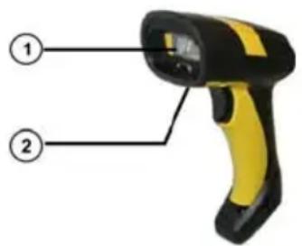
The laser light is visible to the human eye and is emitted from the output window ①.
Laser warning and classification label ②.

CAUTION
Use of controls or adjustments or performance of procedures other than those specified herein may result in exposure to hazardous visible laser light.
The laser scanner utilizes a low-power laser diode. Although staring directly at the laser beam momentarily causes no known biological damage, avoid staring at the beam as one would with any very strong light source, such as the sun. Avoid that the laser beam hits the eye of an observer, even through reflective surfaces such as mirrors, etc.
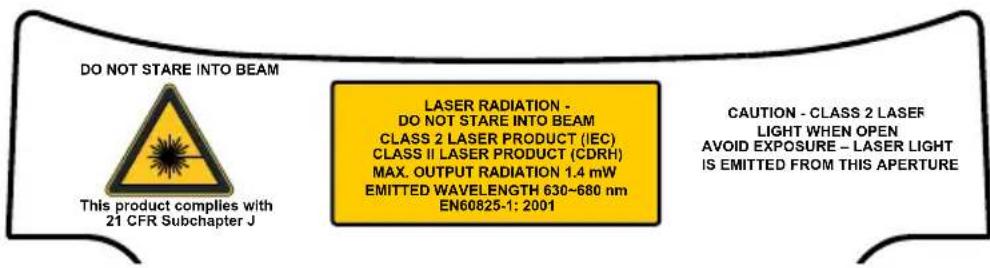
The following information is shown on the laser scanner device class label:
ITALIANO
Classe 2: LUCE LASER
NON FISSARE IL RAGGIO
APPARECCHIO LASER DI CLASSE 2
FRANÇAIS
Classe 2: RAYON LASER
EVITER DE REGARDER LE RAYON
APPAREIL LASER DE CLASSE 2
DEUTSCH
Class 1 LED product.
This product conforms to EN60825-1:2001.
IC (INDUSTRY CANADA)
Operation is subject to the following two conditions: (1) this device may not cause interference, and (2) this device must accept any interference, including interference that may cause undesired operation of the device.
Psion Teklogix Inc.
2100 Meadowvale Boulevard,
Mississauga, Ontario, Canada L5N 7J9
http://www.psionteklogix.com

08
dichiara che
declares that the
déclare que le
are in conformity with the requirements of the European Council Directives listed below:
This declaration is based upon compliance of the products to the following standards:
INFORMATION TECHNOLOGY EQUIPMENT - SAFETY -
PART 1: GENERAL REQUIREMENTS
April 16, 2008
NOTES
1 INTRODUCTION .... 1
2 INSTALLATION....2
2.1 PowerScan ^® D8330 Interface Cable Connections 2
2.2 BC-80X0 Interface Cable Connections 4
2.3 RS-232 Connection....5
2.4 USB 5
2.5 IBM USB POS....6
2.6 WEDGE Connection 7
2.7 PEN Emulation Connection....7
2.8 Network Connections....8
2.8.1 BC-8060 Network Connectors 8
2.8.2 Network Cabling....9
2.8.3 Network Termination....10
2.9 PowerScan ^® M8300 Battery Maintenance 11
2.9.1 Battery Charging.... 11
2.9.2 Replacing PowerScan ^® M8300 Batteries 11
2.10 Mounting The BC-80X0 / C-8000 Cradle 12
2.10.1 Desktop Mounting 13
2.10.2 Wall Mounting 16
3 POWERSCAN ® M8300 SYSTEM AND NETWORK LAYOUTS...... 18
3.1 Stand-alone Layouts 18
3.1.1 Point-to-Point Reader Layout.... 18
3.1.2 Stand-Alone Layout with Multiple Readers 18
3.1.3 Multiple Stand-Alone Layouts 19
3.1.4 C-BOX Layout....20
3.2 Multidrop STAR-System™ Network Layouts 21
3.2.1 Host Master Layout.... 21
3.2.2 BC-8060 Master Layout 22
3.2.3 Master BC-8060 Network Troubleshooting 23
4 CONFIGURATION....24
4.1 Configuration Methods....24
4.1.1 Reading Configuration Bar Codes 24
4.1.2 Using the Original Manufacturer's Datalogic Aladdin™ 24
4.1.3 Copy Command 25
4.1.4 Sending Configuration Strings from Host 25
4.2 Setup Procedures 25
4.3 PowerScan ^® D8330 Setup 27
4.4 PowerScan ^® M8300/BC-80X0 Point-to-Point Setup 27
4.5 PowerScan ^® M8300/BC-80X0 Stand-Alone Setup 28
4.5.1 Using Multiple M-Series Readers with Same Cradle 30
4.5.2 PowerScan ^® M8300/STAR-Modem ^TM in Stand-Alone Mode 31
4.6 PowerScan ^® M8300/STAR-System ^TM Setup 32
4.7 BC-8060 STAR-System™ Network Setup 34
4.8 Interface Selection 36
4.9 USB Reader Configuration....39
4.10 Changing Default Settings 41
5 REFERENCES 140
5.1 RS-232 Parameters 140
5.1.1 Handshaking....140
5.1.2 ACK/NACK Protocol 141
5.1.3 FIFO....142
5.1.4 RX Timeout.... 143
5.2 Pen Parameters....143
5.2.1 Minimum Output Pulse.... 143
5.2.2 Conversion to Code 39 and Code 128....143
5.2.3 Overflow....144
5.2.4 Output and Idle Levels 144
5.2.5 Inter-Block Delay.... 145
5.3 Network Parameters 145
5.3.1 Slave Address Range First/Last.... 145
5.3.2 Network Warning Message 145
5.3.3 Reception Warning Message.... 146
5.3.4 Master Header/Terminator Selection 146
5.4 Data Format....146
5.4.1 Header/Terminator Selection 146
5.4.2 Define Special Key Sequence.... 148
5.4.3 Address Stamping....155
5.4.4 Address Delimiter.... 155
5.4.5 Time Stamping Format 156
5.4.6 Time Stamping Delimiter....156
5.5 Power Save....156
5.5.1 Sleep State 156
5.5.2 Enter Sleep Timeout 157
5.6 Reading Parameters 157
5.6.1 Trigger Signal.... 157
5.6.2 Trigger Click....157
5.6.3 Trigger-Off Timeout.... 157
5.6.4 Reads per Cycle 157
5.6.5 Safety Time....158
5.7 Decoding Parameters 158
5.8 Advanced Formatting....159
5.8.1 Match Conditions 159
5.9 Radio Parameters (M8300 Series Only) 159
5.9.1 Radio Protocol Timeout 159
5.9.2 Radio RX Timeout.... 160
5.9.3 Power-Off Timeout.... 160
5.9.4 Transmission Mode....161
5.9.5 Beeper Control for Radio Response 161
5.9.6 Single Store 162
5.9.7 Batch Mode....162
5.9.8 Find Me (PowerScan ^ M8300 only).... 163
5.10 Display Parameters (Some M8300 Models only) 164
5.10.1 Display Mode 164
5.11 Configuration Editing Commands 165
5.12 Custom Default Configuration.... 166
5.13 Code Type Recognition 166
5.14 Configuration Copying Commands 167
5.14.1 Copy PowerScan ^® D8330 Series 167
5.14.2 Copy PowerScan ^® M8300 Series 168
5.14.3 Copy BC-80X0 169
5.15 Default Parameters for POS Terminals....170
5.16 Firmware Upgrade 171
6 MESSAGE FORMATTING 172
6.1 Messages from Host to Reader 172
6.1.1 Cursor Control.... 173
6.1.2 Font Selection 174
6.1.3 Clearing Display.... 174
6.1.4 LED and Beeper Control 174
6.1.5 Setting RTC 175
6.2 Messages from SCANNER Command Keys....175
7 TECHNICAL FEATURES....177
7.1 PowerScan ^® D8330 177
7.2 PowerScan ^® M8300 178
7.3 BC-80X0 / C-8000 179
7.4 System and Radio Features....180
7.5 Status Indicators 180
7.6 Reading Diagrams 183
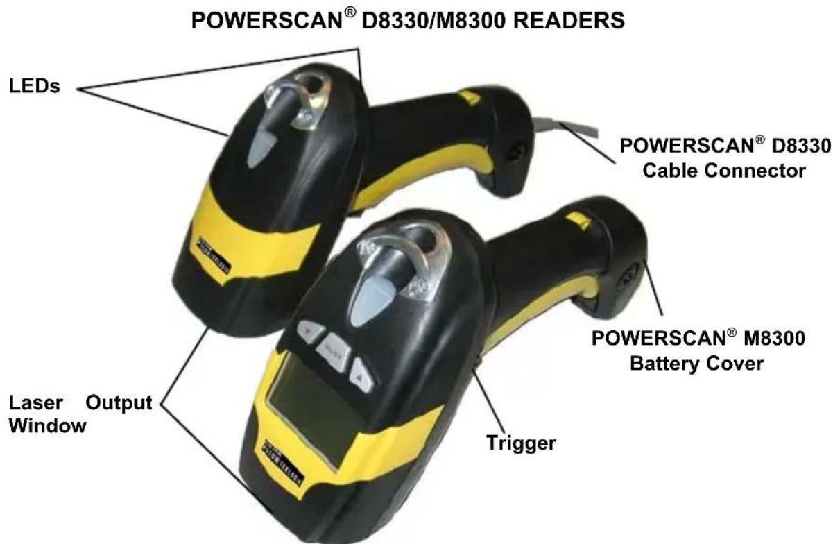
Figure A – PowerScan® D8330/M8300 Series Readers
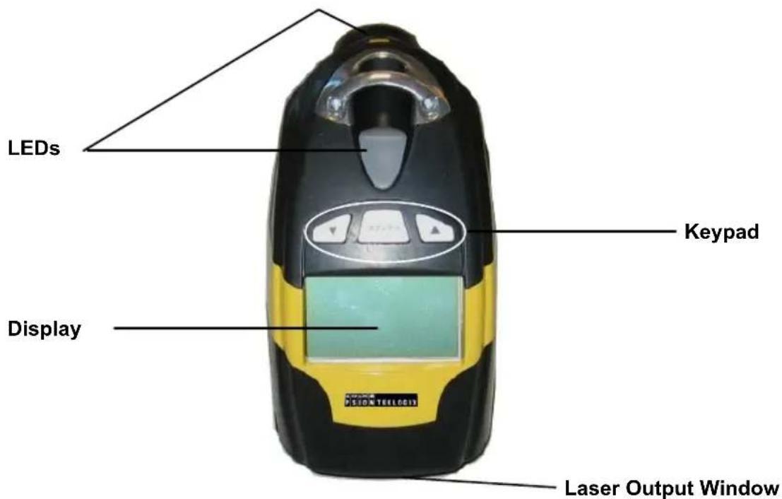
Figure B – PowerScan® M8300 Series Readers with Display
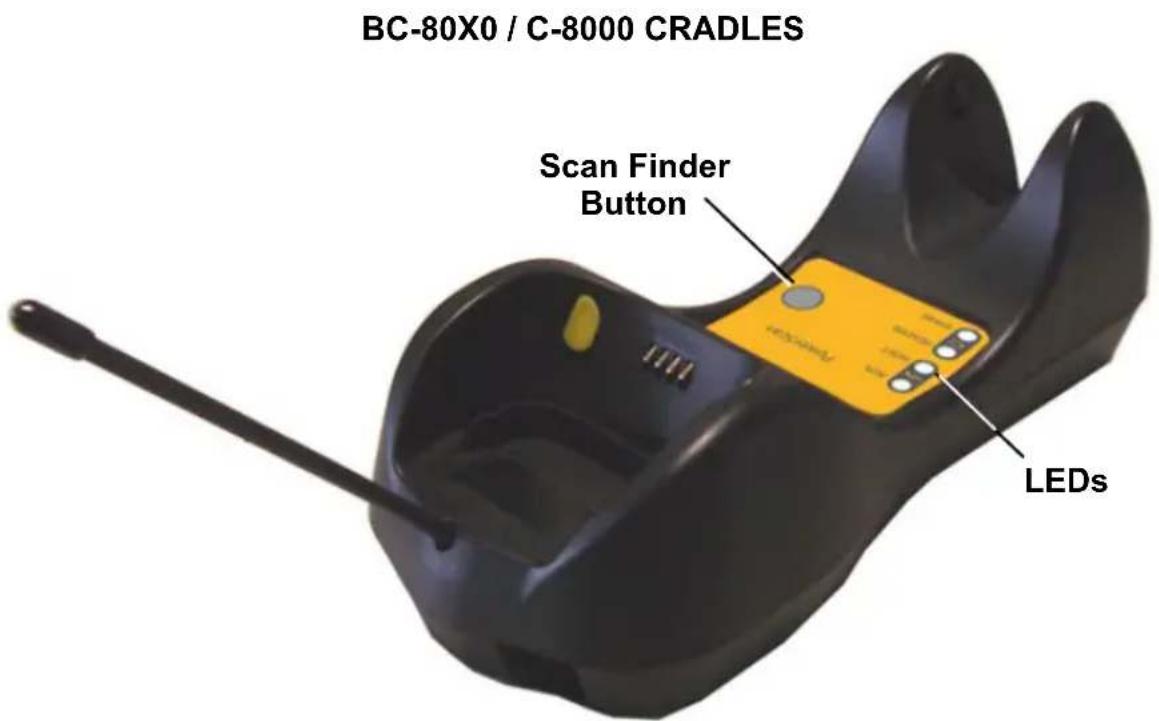
Figure C - BC-8000
The label on the cradle contains LED indicators and a scan finder button. When the button is pressed, the cradle transmits a “broadcast” message. All properly configured scanners (Radio RX Timeout set to keep the radio “awake”) linked to that base (through a bind or a join sequence) and within radio range coverage will emit a beep sequence once every 2 seconds for 30 seconds. A scanner is considered to be linked when the last transmission ends properly.
The scan finder works only in stand-alone layout (point to point or multiple readers).
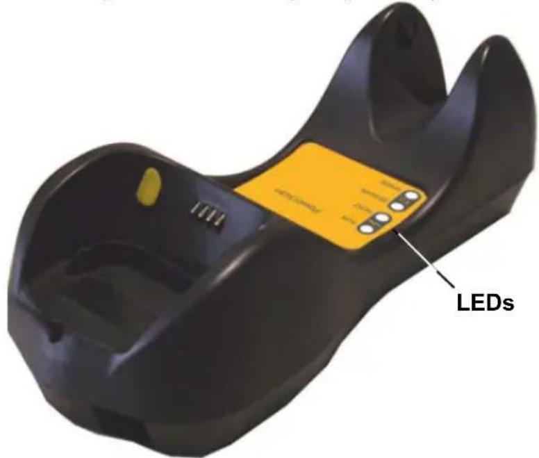
Figure D - C-8000
1 INTRODUCTION
Psion Teklogix renews its range of industrial laser scanners introducing the PowerScan® family: PowerScan® D8330 and PowerScan® M8300. Robustness and ergonomics remain unsurpassed: clearly audible beeper and bright "good read" LEDs for areas where noise levels are normally high; the aim mode, which helps point to the right code, has now been extended to the whole PowerScan® family. Optical parts are completely suspended on shock absorbers and a careful choice of the body materials, such as the co-moulded rubber, protect the PowerScan® from damage due to "falls".
New enhanced architecture, based on an M16 high-speed microprocessor, enables exceptional performance for promptness and reading speed of standard codes as well as the ability to read poorly printed and damaged codes. Patented Puzzle Solver Technology™ adds further strength to the PowerScan® powerful engine.
In all applications where mobility is a value, the new PowerScan ^® M8300 represents the key to increase productivity and flexibility in the working area. PowerScan ^® M8300 communicates through a low power, license-free radio in the 433 MHz band (910 MHz for USA version) and allows bi-directional communication between the base station and the host. PowerScan ^® M8300 also includes a display and a 3 push-button keypad. Thanks to these features, the operator can receive information from the host, interact with the central system and visualize the code read. The cordless system offers scalable solutions to solve simple applications and complex projects:
- Point to point: each reader is associated with its own base station;
- Multipoint: up to 32 readers transmit data to one base station;
- Network: to cover a wide area, connecting up to 16 bases and 512 readers simultaneously working in automatic roaming.
PowerScan ^® M8300 is 100% compatible with STAR-System ^™ , the new Psion Teklogix RF narrow band solution for mobile applications that provides the widest family of narrow band devices on the market.
Your PowerScan ^® reader is supplied with its own Quick Reference Guide, which provides connection, diagrams, reading diagrams, basic application parameter settings, default values, and specific technical features. You can use either the Quick Reference Guide or this Manual for initial configuration in order to set the default values and select the interface for your application. This manual provides all the necessary information for complete mechanical installation and system software configuration.
2 INSTALLATION

CAUTION
Connections should always be made with power OFF!
2.1 POWERSCAN ^® D8330 INTERFACE CABLE CONNECTIONS
The PowerScan® D8330 reader incorporates a multi-standard interface, which can be connected to a Host by plugging the correct interface cable into the connector and closing the cable cover.
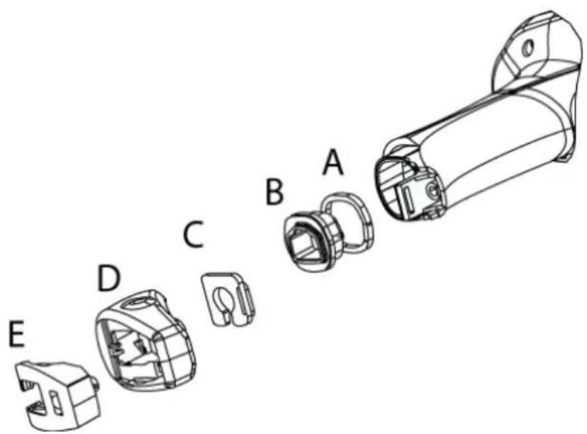
A. Rubber gasket
B. Plastic boot
C. Cable spacer
D. Cover
E. Strain relief
Follow the given procedure for correct cable insertion:
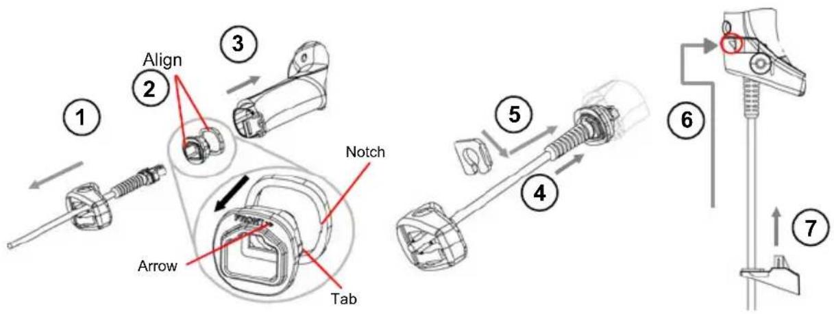
① Slip the cover over the cable.
② Push the plastic boot into the rubber gasket. Take care that the tab on the plastic boot is aligned with the notch in the rubber gasket.
③ Push the plastic boot and gasket into the handle. Ensure that the "Front" marking on the plastic boot is facing out, with the arrow pointing towards the front of the scanner.
④ Insert the cable into the socket of the plastic boot.
⑤ Insert the cable spacer into the cable wire and slide it towards the handle.
⑥ Push the cover along the cable towards the reader, and hook it over the yellow "tooth".
⑦ Insert the strain relief into the cover and tighten the screw to fix the whole assembly to the reader handle.

CAUTION
Connections should always be made with power OFF!
2.2 BC-80X0 INTERFACE CABLE CONNECTIONS
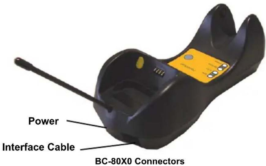
The BC-80X0 incorporates a multi-standard interface, which can be connected to a Host by simply plugging the correct interface cable into the Host connector, placed on the base of the cradle. In addition the cradle must be connected to an external power supply.
natural_image
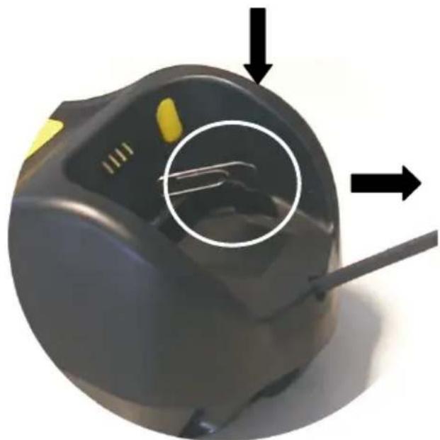
Close-up of a black electronic device with a circular annotation highlighting internal components, marked by arrows (no text or symbols present)Disconnecting the BC-80X0 Cable
To disconnect the cable, insert a paper clip or other similar object into the hole corresponding to the Host connector on the body of the cradle.
Push down on the clip while unplugging the cable.
2.3 RS-232 CONNECTION
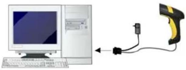
natural_image
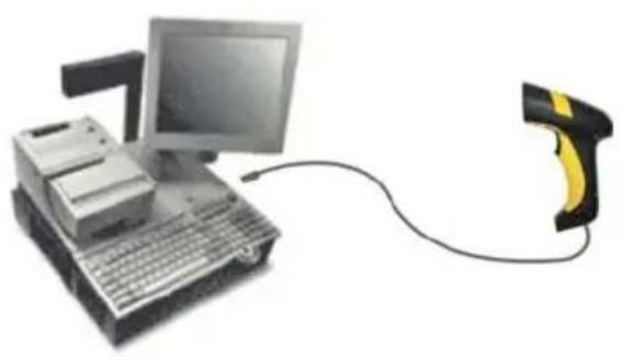
Illustration of a desktop computer connected to a handheld device via cable (no text or symbols visible)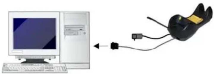
natural_image
Illustration of a desktop computer connected to a black mouse (no text or symbols present)2.4 USB
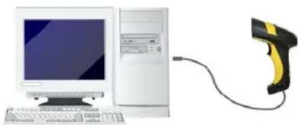
natural_image
Illustration of a desktop computer connected to a handheld device via cable (no text or symbols visible)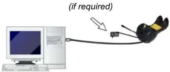
2.5 IBM USB POS
natural_image
Illustration of a vintage desktop computer with monitor and keyboard, connected to a handheld device (no text or symbols visible)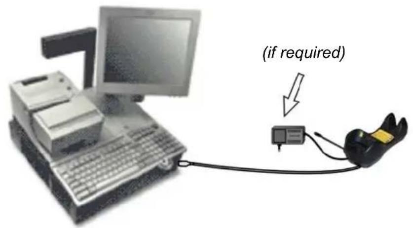
natural_image
Illustration of a desktop computer connected to a handheld device via cable (no text or symbols visible)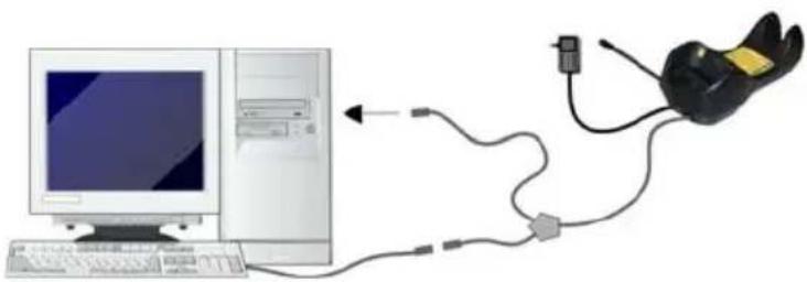
natural_image
Illustration of a desktop computer connected to a black headset via cable (no text or symbols)2.7 PEN EMULATION CONNECTION
natural_image
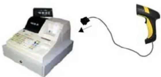
Illustration of a white handheld cash register with a black label and cable, connected to a yellow handheld device (no text or symbols visible)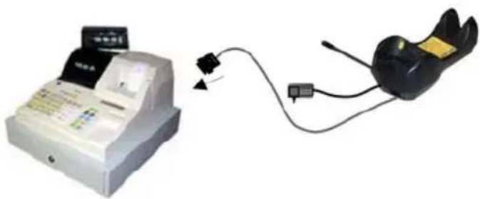
natural_image
Two electronic devices connected by a cable, one with a card and the other a black device (no visible text or symbols)2.8 NETWORK CONNECTIONS
2.8.1 BC-8060 Network Connectors
The multidrop network is a bus system which is propagated from one BC-8060 cradle to another using individual cables. This is possible thanks to the RS-485 connector on the front panel of the cradle.
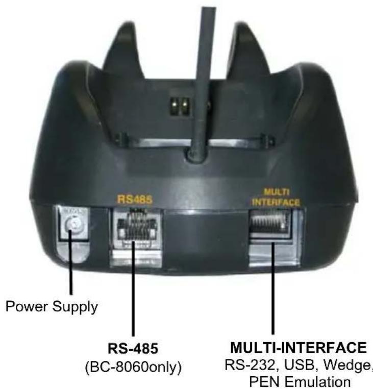
All cradles are connected together within the bus system through the Psion Teklogix RS-485 splitter cable (CAB-428, part number 90A051950), which must be inserted in the RS-485 cradle connector.
Obviously cable length is to be kept to a minimum as with all bus systems.
2.8.2 Network Cabling
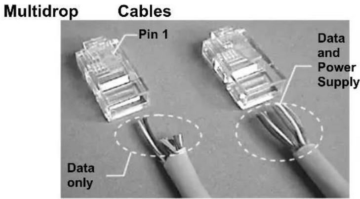
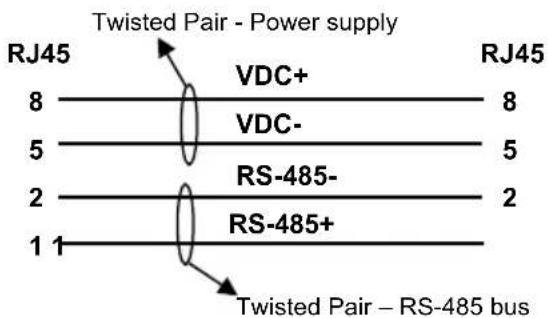
The Multidrop line is made using RJ45 connectors and a cable having the following specifications:
• twisted pair AWG 24 wires
• 120 Ω impedance
• maximum network cable length 1200 meters
| Pin | Function | |
| 1 | RS-485 | + |
| 2 | RS-485 | - |
| 3 | N.C. | |
| 4 | VDC | - |
| 5 | VDC | - |
| 6 | N.C. | |
| 7 | VDC | + |
| 8 | VDC | + |
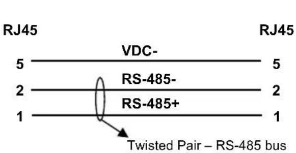
flowchart
graph TD
    A["8"] --> B["VDC+"]
    C["5"] --> D["VDC-"]
    E["2"] --> F["RS-485-"]
    G["1"] --> H["RS-485+"]
    I["RJ45"] --> J["Twisted Pair - Power supply"]
    K["RJ45"] --> L["Twisted Pair – RS-485 bus"]
When wiring the multidrop cables, note the following:
Pin 8 (or 7) can be connected only if the power has to be propagated from a cradle to a STARGATE™ base station or STAR-Box™ converter via the cable.
Pins 5 (or 4) should always be connected as reference ground.
To avoid excessive voltage drop, it is recommended not to propagate power between BC-8060 cradles when used as battery chargers but to supply each cradle individually. The total number of devices, which can be connected to a single power supply, depends on the power supply voltage, the wire length and resistance and therefore the voltage drop. Do NOT connect VDC+ between network devices that are individually powered.
2.8.3 Network Termination
The first and last cradles of the chain (the two ends of the bus) must be properly terminated. The cradle has an internal terminator that can be selected via jumper. For this selection you must open the device.
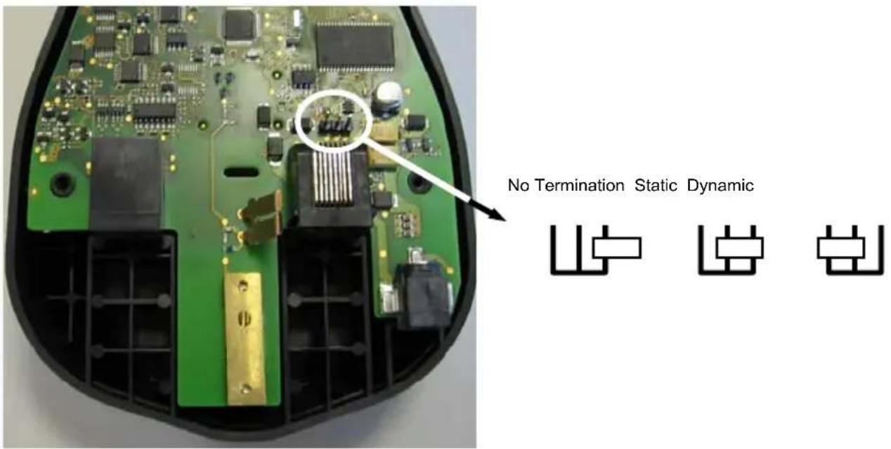
Terminator for Multidrop Network
Static termination works for all network configurations. However, the network is always under load even when no data transmission takes place.
Dynamic termination can be used for baud rates at or above 38400 and provides less load on the network when idle.
2.9 POWERSCAN ^® M8300 BATTERY MAINTENANCE
2.9.1 Battery Charging
Once the system is connected and powered, you can place the PowerScan® M8300 into the cradle to charge the battery.
When the reader is correctly inserted in the cradle, the "Reader" red LED on the cradle goes on to indicate that the battery is charging. The "Reader" green LED on the cradle goes on when the battery is completely charged.
2.9.2 Replacing PowerScan ^® M8300 Batteries
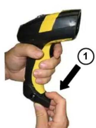
To change the batteries in your PowerScan® M8300 scanner, press the black button or unscrew the fixing screw on the handle cover and extract the battery pack from the reader handle.
natural_image
Close-up of hands holding a handheld device with yellow and black buttons, labeled with number 1 (no text or symbols on the device itself)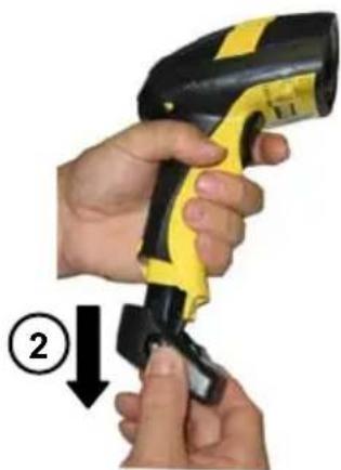
natural_image
Close-up of hands using a handheld device to adjust a black cable or cable (no text or symbols visible)
NOTE
When the batteries are extracted from the scanner, the timer maintains the current hour and date for about 1 minute.
Replace the old battery pack with a new one by inserting it within the reader handle and pushing it until it clicks.

WARNING
Do not incinerate, disassemble, short terminals or expose to high temperature. Risk of fire, explosion. Use specified charger only. Risk of explosion if the battery is replaced by an incorrect type. Dispose of the batteries as required by the relevant laws in force.
2.10 MOUNTING THE BC-80X0 / C-8000 CRADLE
The cradle package contains the following items:
BC-80X0 / C-8000 Cradle
BC-80X0 Cradle Quick Reference Guide / C-8000 Cradle Quick Reference Guide
BC-8000 Antenna 2 wall-mounting lock hinges
2 adhesive strips 4 rubber feet
1 horizontal base 1 inclined base
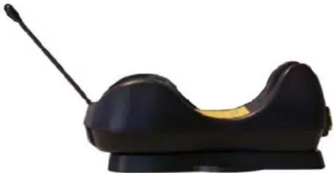
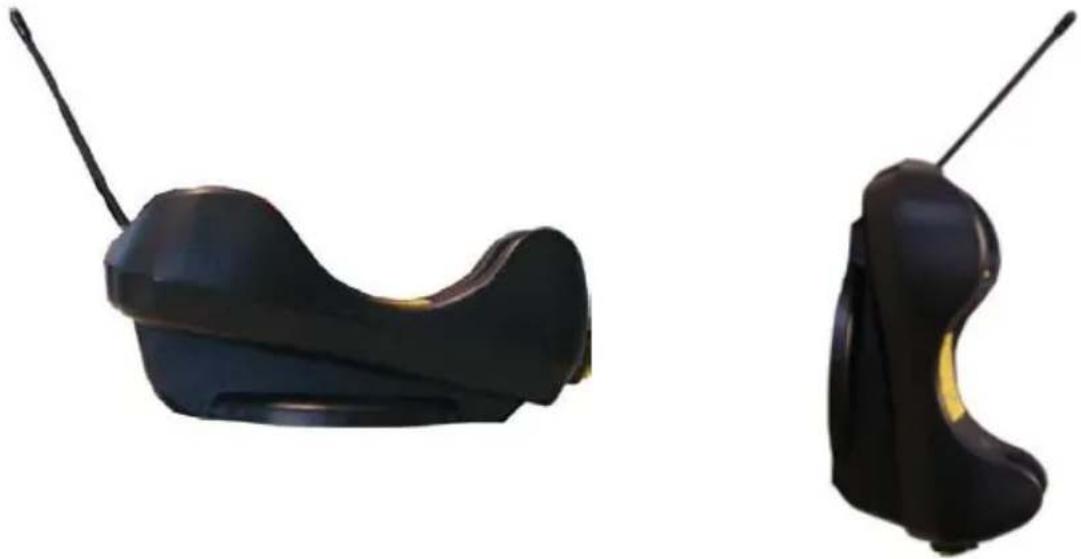
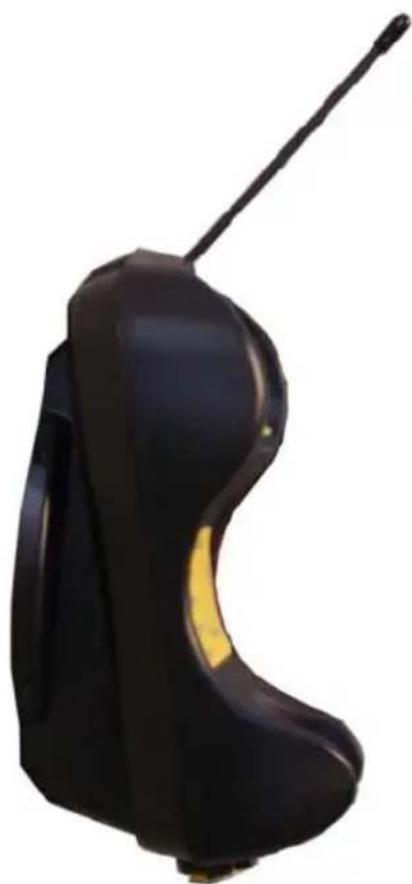
The cradle (either BC-80X0 or C-8000) can be mounted for portable or fixed desktop usage, or it can be fixed to a wall. The horizontal base allows portable and fixed desktop usage, while the inclined base provides desktop and wall mounting guaranteeing a comfortable handling of the PowerScan ^® M8300 reader.
natural_image
Black and yellow object resembling a stylized bow or button device (no text or symbols visible)BC-80X0/C-8000 Cradle mounted on the Horizontal Base
natural_image
Two black athletic shoe covers with antenna, shown from different angles (no text or symbols visible)BC-80X0/C-8000 Cradle mounted on the Inclined Base
2.10.1 Desktop Mounting
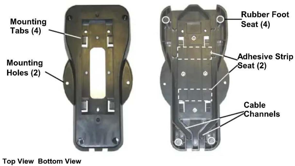
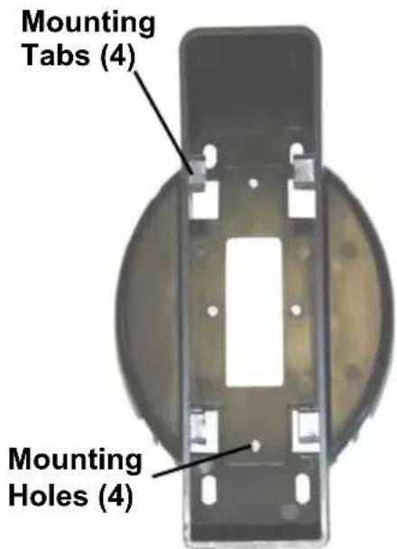
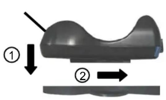
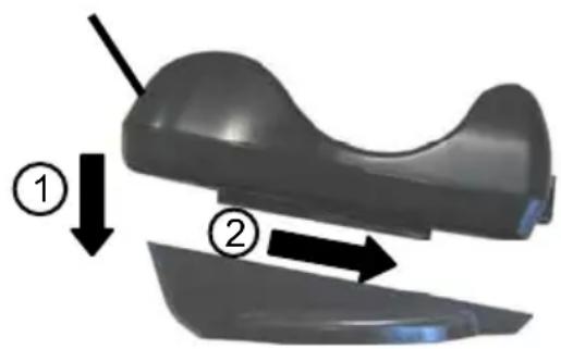
For desktop usage, you can mount the cradle either on the horizontal base, for reduced overall dimensions, or on the inclined base for a more ergonomic taking out and insertion of the reader onto the cradle.
Horizontal base
Inclined base
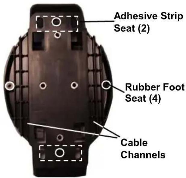
Top View Bottom View
Portable Desktop Use
- Correctly position the BC-80X0/C-8000 onto the base by sliding it along the mounting tabs until aligned.
natural_image
3D model of a car seat with two directional arrows indicating movement or change (no text or symbols present)- Carefully clean the rubber foot seats of the base to remove any impurities that could reduce adhesion.
- Remove the protective plastic from the rubber feet and stick them onto the bottom surface of the base.
- If mounting the BC-80X0 cradle, insert the antenna in the appropriate hole on the body of the cradle and screw it clockwise until tight.
Fixed Desktop Use
For fixed desktop installation, use the adhesive strips or fixing screws (not provided) according to your needs.
For mounting with adhesive strips:
- Position the cradle onto the base by sliding it along the mounting tabs until aligned.
- Carefully clean the adhesive strip seats of the base to remove any impurities that could reduce adhesion.
-
Remove the protective plastic from one side of the adhesive strips and stick them onto the base surface.
-
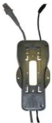
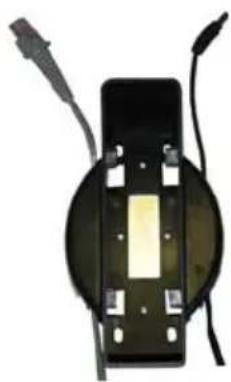
Position the cables to be connected to the BC-80X0/C-8000 cradle along the dedicated channels, as shown in the figures below:
natural_image
Electronic device with two leads and a central rectangular component (no visible text or symbols)Horizontal Base Inclined Base
natural_image
Close-up of a black electronic component with wires and connectors (no visible text or symbols)-
Remove the plastic from the other side of the strips and affix the base to the table.
-
If mounting the BC-80X0 cradle, insert the antenna in the appropriate hole on the body of the cradle and screw it clockwise until tight.
For mounting with screws:
-
Position the cables to be connected to the BC-80X0/C-8000 cradle along the dedicated channels, as shown in the figures above.
-
Position the base on the table and affix it by means of the screws (not provided).
-
Position the cradle on the base by sliding it along the mounting tabs until aligned.
-
If mounting the BC-80X0 cradle, insert the antenna in the appropriate hole on the body of the cradle and screw it clockwise until tight.
2.10.2 Wall Mounting
natural_image
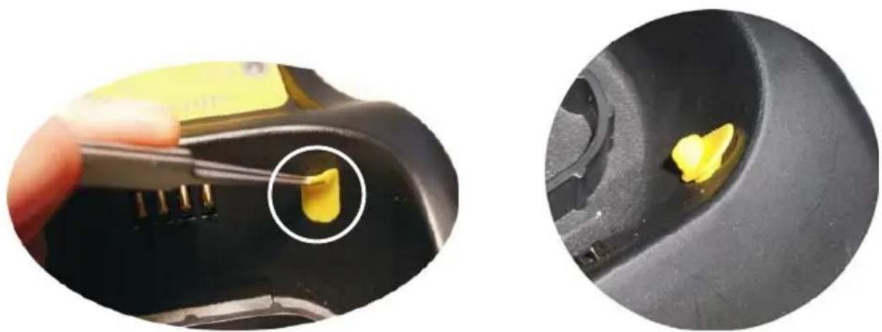
Black and yellow object resembling a stylized musical instrument or device, with no visible text or symbols.- Remove the yellow caps and insert the two wall mounting lock hinges provided with your cradle.
natural_image
Close-up of a device with a yellow plastic clip being inserted, alongside its close-up view showing the interior component (no text or symbols visible)- Position the cables to be connected to the BC-80X0/C-8000 cradle along the dedicated channels (see figures on page 15).
If using the adhesive strips:
a. Carefully clean the adhesive strip seats of the base to remove any impurities that could reduce adhesion.
b. Remove the protective plastic from one side of the adhesive strips and stick them onto the base surface.
c. Remove the plastic from the other side of the strips and affix the base to the wall as indicated in the figure below.
If using the mounting screws:
- Using the mounting holes on the base as a pattern, mark the wall where you desire to mount the BC-80X0/C-8000.
- Drill the appropriate size holes and insert the threaded dowels (not provided) into the holes.
- Position the base on the wall as indicated in the figure below and affix it by means of the screws (not provided).

natural_image
Black elongated object with a small white mark on the side, resembling a stylized blade or abstract form (no text or symbols visible)Inclined Base Wall-mounting
- Attach the cradle on the base by sliding it along the mounting tabs until aligned.
- If mounting the BC-80X0 cradle, insert the antenna in the appropriate hole on the body of the cradle and screw it clockwise until tight.
3 POWERSCAN ^® M8300 SYSTEM AND NETWORK LAYOUTS
There are two basic system layouts that can be employed: Stand-alone systems (including Point-to-Point layouts) and Multidrop STAR-System™ Networks.
3.1.2 Stand-Alone Layout with Multiple Readers
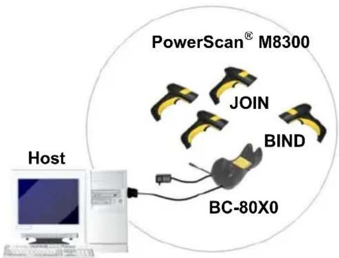
In stand-alone systems, each cradle is connected to a single Host.
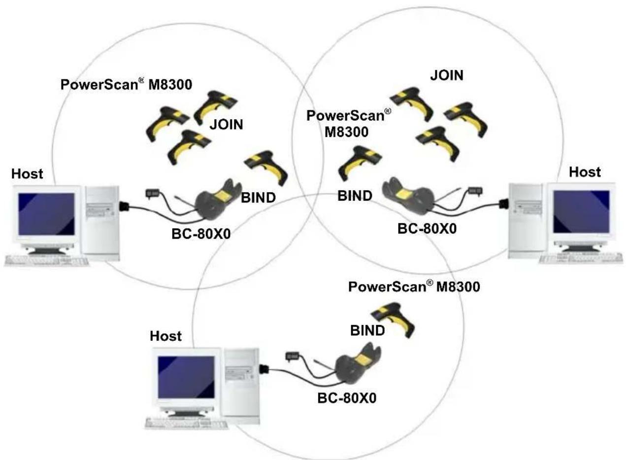
3.1.3 Multiple Stand-Alone Layouts
Many stand-alone connections can operate in the same physical area without interference, provided all readers and cradles in the system have different addresses.
flowchart
graph TD
    subgraph Host
        A["Computer"] --> B["PowerScan® M8300"]
        B --> C["BC-80X0"]
        D["Computer"] --> E["PowerScan® M8300"]
        E --> F["BC-80X0"]
        G["Computer"] --> H["PowerScan® M8300"]
        H --> I["BC-80X0"]
    end

    subgraph PowerScan® M8300
        J["Computer"] --> K["PowerScan® M8300"]
        L["PowerScan® M8300"]
        M["PowerScan® M8300"]
        N["PowerScan® M8300"]
        O["PowerScan® M8300"]
        P["PowerScan® M8300"]
        Q["PowerScan® M8300"]
        R["PowerScan® M8300"]
        S["PowerScan® M8300"]
        T["PowerScan® M8300"]
        U["PowerScan® M8300"]
        V["PowerScan® M8300"]
        W["PowerScan® M8300"]
        X["PowerScan® M8300"]
        Y["PowerScan® M8300"]
        Z["PowerScan® M8300"]
    end

    subgraph PowerScan® M8300
        AA["Computer"] --> AB["PowerScan® M8300"]
        AC["PowerScan® M8300"]
        AD["PowerScan® M8300"]
        AE["PowerScan® M8300"]
        AF["PowerScan® M8300"]
        AG["PowerScan® M8300"]
        AH["PowerScan® M8300"]
        AI["PowerScan® M8300"]
        AJ["PowerScan® M8300"]
        AK["PowerScan® M8300"]
        AL["PowerScan® M8300"]
        AM["PowerScan® M8300"]
        AN["PowerScan® M8300"]
        AO["PowerScan® M8300"]
        AP["PowerScan® M8300"]
        AQ["PowerScan® M8300"]
        AR["PowerScan® M8300"]
        AS["PowerScan® M8300"]
    end

    subgraph PowerScan® M8300
        AT["Computer"] --> AU["PowerScan® M8300"]
        AV["PowerScan® M8300"]
        AW["PowerScan® M8300"]
        AX["PowerScan® M8300"]
        AY["PowerScan® M8300"]
        AZ["PowerScan® M8300"]
        BA["PowerScan® M8300"]
        BB["PowerScan® M8300"]
        BC["PowerScan® M8300"]
        BD["PowerScan® M8300"]
        BE["PowerScan® M8300"]
        BF["PowerScan® M8300"]
        BG["PowerScan® M8300"]
        BH["PowerScan® M8300"]
        BI["PowerScan® M8300"]
        BJ["PowerScan® M8300"]
        BK["PowerScan® M8300"]
        BL["PowerScan® M8300"]
        BM["PowerScan® M8300"]
        BN["PowerScan® M8300"]
    end

    subgraph PowerScan® M8301
        BO["Computer"] --> BP["PowerScan® M8301"]
        BQ["PowerScan® M8301"]
        BR["PowerScan® M8301"]
        BS["BIN"] --> BT["BIN"]
    end

    subgraph PowerScan® M8302
        BU["Computer"] --> BV["BIN"] --> BW["BIN"]
    end

    subgraph PowerScan® M8303
        BX["BIN"] --> BY["BIN"]
    end

    subgraph PowerScan® M8304
        BZ["BIN"] --> CA["BIN"]
    end

    subgraph PowerScan® M8305
        DB["BIN"] --> DC["BIN"]

    subgraph PowerScan® M8311
        DD["BIN"] --> DJ["BIN"]

    subgraph PowerScan® M8312
        DBB["BIN"] --> DCB["BIN"]

    subgraph PowerScan® M8313
        DBC["BIN"] --> DCC["BIN"]

    subgraph PowerScan® M8314
        DBD["BIN"] --> DCD["BIN"]

    subgraph PowerScan® M8315
        DBE["BIN"] --> DCE["BIN"]

    subgraph PowerScan® M8316
        DBF["BIN"] --> DCF["BIN"]

    subgraph PowerScan® M8317
        DBG["BIN"] --> DCG["BIN"]

    subgraph PowerScan® M8318
        DBH["BIN"] --> DCH["BIN"]

    subgraph PowerScan® M8319
        DBI["BIN"] --> DCJ["BIN"]

    subgraph PowerScan® M8321
        DBJ["BIN"] --> DCK["BIN"]

    subgraph PowerScan® M8322
        DBK["BIN"] --> DCL["BIN"]

    subgraph PowerScan® M8323
        DBL["BIN"] --> DCM["BIN"]

    subgraph PowerScan® M8324
        DBM["BIN"] --> DCN["BIN"]

    subgraph PowerScan® M8325
        DBN["BIN"] --> DCO["BIN"]

    subgraph PowerScan® M8326
        DBO["BIN"] --> DCP["BIN"]

    subgraph PowerScan® M8327
        DBP["BIN"] --> DCQ["BIN"]

    subgraph PowerScan® M8328
        DBQ["BIN"] --> DCR["BIN"]

    subgraph PowerScan® M8329
        DBR["BIN"] --> DCS["BIN"]

    subgraph PowerScan® M8331
        DBS["BIN"] --> DCT["BIN"]

    subgraph PowerScan® M8332
        DBT["BIN"] --> DCU["BIN"]

    subgraph PowerScan® M8333
        DBU["BIN"] --> DCV["BIN"]

    subgraph PowerScan® M8334
        DBV["BIN"] --> DCW["BIN"]

    subgraph PowerScan® M8335
        DBW["BIN"] --> DCX["BIN"]

    subgraph PowerScan® M8336
        DBX["BIN"] --> DCY["BIN"]

    subgraph PowerScan® M8337
        DBY["BIN"] --> DCZ["BIN"]

    subgraph PowerScan® M8338
        DBZ["BIN"] --> DCXB["BIN"]

    subgraph PowerScan® M8339
        DBWb["BIN"] --> DCYb["BIN"]

    subgraph PowerScan® M8341
        DBXb["BIN"] --> DCYbB["BIN"]

    subgraph PowerScan® M8342
        DBYb["BIN"] --> DCYbB["BIN"]

    subgraph PowerScan® M8343
        DBXbB["BIN"] --> DCYbBb["BIN"]

    subgraph PowerScan® M8344
        DBYbB["bin"] --> DCYbB["bin"]

    subgraph PowerScan® M8345
        DBXbB["bin"] --> DCYbB["bin"]

    subgraph PowerScan® M8346
        DBYbB["bin"] --> DCYbB["bin"]

    subgraph PowerScan® M8347
        DBXbB["bin"] --> DCYbB["bin"]

    subgraph PowerScan® M8348
        DBYbB["bin"] --> DCYbB["bin"]

    subgraph PowerScan® M8349
        DBYbB["bin"] --> DCYbB["bin"]

    subgraph PowerScan® M8351
        DBXbB["bin"] --> DCYbB["bin"]

    subgraph PowerScan® M8352
        DBYbB["bin"] --> DCYbB["bin"]

    subgraph PowerScan® M8353
        DBXbB["bin"] --> DCYbB["bin"]

    subgraph PowerScan® M8354
        DBYbB["bin"] --> DCYbB["bin"]
Multiple Stand-alone Systems in the Same Area
Since the cradles can communicate to multiple PowerScan® M8300 readers, you might find it useful to employ one or more C-8000 battery chargers in addition to the BC-80X0 cradle, so that the battery re-charging operation can be performed for several scanners at the same time.
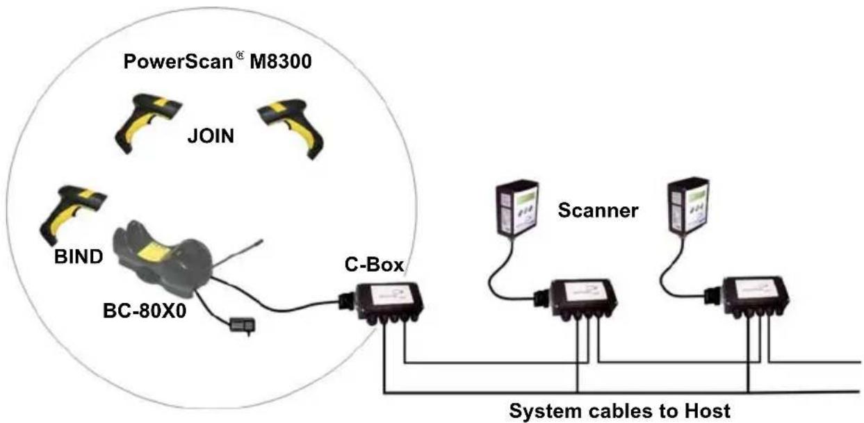
3.1.4 C-BOX Layout
flowchart
graph TD
    A["PowerScan® M8300"] --> B["JOIN"]
    A --> C["BIND"]
    A --> D["BC-80X0"]
    C --> E["C-Box"]
    D --> E
    E --> F["Scanner"]
    E --> G["System cables to Host"]
In this layout the BC-80X0 cradle is connected by a dedicated cable using the RS-232 interface to a C-BOX connection box as part of a fixed scanner network. This allows the flexibility of a hand-held reading station integrated into a variety of fixed scanning applications so that all readers (both fixed and hand-held), in the system provide communications to the Host.
The various C-BOX models provide many interface types for the Host system such as RS-232, RS-485, Profibus.
3.2 MULTIDROP STAR-SYSTEM™ NETWORK LAYOUTS
Even though many stand-alone systems can operate in the same physical area without interfering with each other, it may be desirable to bridge data from multiple base stations in a network to a single Host. PowerScan® M8300 readers are compatible with STAR-System™ networks. These networks provide seamless active roaming for any RF reading device in the system.
3.2.1 Host Master Layout
flowchart
graph TD
    subgraph_Port_A["Internal Termination"]
        A1["Port A"] -->|RS-232| B1["Port B"]
        B1 -->|RS-485 + VDC| RS4["Port C"]
        RS4 -->|RS-485 Only| D1["Port D"]
        D1 -->|RS-485 + VDC| CAB["Port C"]
        CAB -->|CAB-428 Splitter| CAB2["Port B"]
    end
    subgraph_Port_B["Internal Termination"]
        B2["Port B"] -->|RS-485 + VDC| RS4
        RS4 -->|RS-485 Only| D2["Port D"]
        D2 -->|RS-485 Only| CAB2
    end
    Port_C["Port C"] -->|RS-485 + VDC| D3["Port D"]
    D3 -->|RS-485 Only| CAB2
    style Port_A fill:#f9f,stroke:#333
    style Port_B fill:#ccf,stroke:#333
    style Port_C fill:#cfc,stroke:#333
    style Port_D fill:#fcc,stroke:#333
    style Port_E fill:#ffc,stroke:#333
    style Port_F fill:#fcc,stroke:#333
    style Port_G fill:#ffc,stroke:#333
    style Port_H fill:#fcc,stroke:#333
    style Port_I fill:#fcc,stroke:#333
    style Port_J fill:#fcc,stroke:#333
    style Port_K fill:#fcc,stroke:#333
    style Port_L fill:#fcc,stroke:#333
    style Port_M fill:#fcc,stroke:#333
    style Port_N fill:#fcc,stroke:#333
    style Port_O fill:#fcc,stroke:#333
    style Port_P fill:#fcc,stroke:#333
    style Port_Q fill:#fcc,stroke:#333
    style Port_R fill:#fcc,stroke:#333
    style Port_S fill:#fcc,stroke:#333
    style Port_T fill:#fcc,stroke:#333
    style Port_U fill:#fcc,stroke:#333
    style Port_V fill:#fcc,stroke:#333
    style Port_W fill:#fcc,stroke:#333
    style Port_Z fill:#fcc,stroke:#333
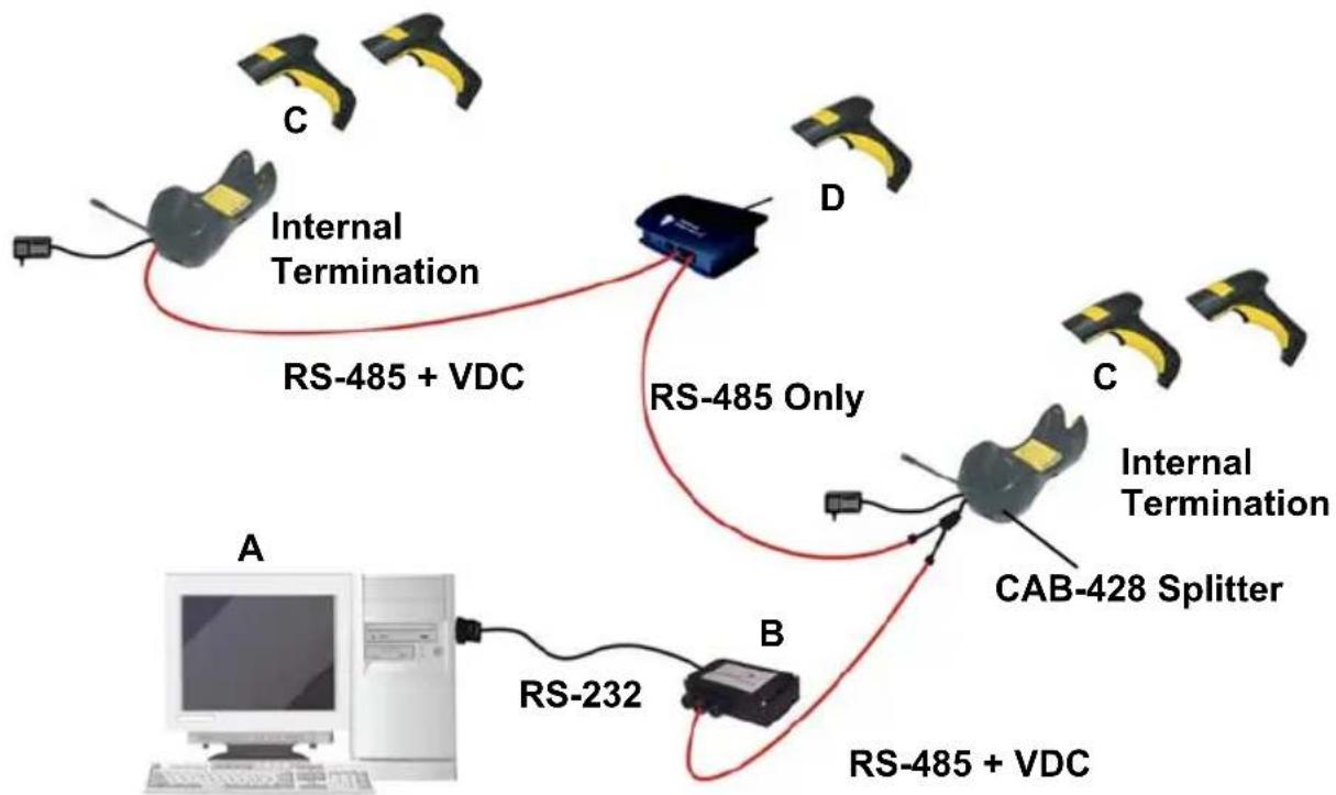
A. Host Master with STAR-Link™
B. STAR-Box ^TM converter
C. BC-8060 slave cradles
D. STARGATE™ base stations
Example Multidrop STAR-System™ Network with Host as Master
In this layout the Host acts as the Master using STAR-Link™ software. The Host is connected in RS-232 to a STAR-Box™ converter, which is connected to the first slave in the RS-485 network. In this way the base stations provide communications between a single Host and all readers in the system. STARGATE™ base stations are used as slaves in this network. The Slaves at the ends of the network must be terminated (see the STARGATE™ and STAR-Box™ Installation Manuals and section 2.8.3).
See sections 4.6 and 4.7 or the original manufacturer's Datalogic Aladdin™ Help On-Line for system configuration specifications.
3.2.2 BC-8060 Master Layout
flowchart
graph TD
    subgraph_A["Internal Termination"]
        A1["Device A"] -->|RS-485 + VDC| A2["Device B"]
        A2 -->|RS-485 Only| A3["Device C"]
        A3 -->|RS-485 Only| A4["Device D"]
        A4 -->|RS-485 Only| A5["Device E"]
    end
    subgraph_B["Internal Termination"]
        B1["Device B"] -->|RS-485 Only| B2["Device C"]
        B2 -->|RS-485 Only| B3["Device D"]
        B3 -->|RS-485 Only| B4["Device E"]
    end
    subgraph_C["Internal Termination"]
        C1["Device C"] -->|RS-485 + VDC| C2["Device D"]
        C2 -->|RS-485 Only| C3["Device E"]
        C3 -->|RS-485 Only| C4["Device F"]
    end
    style A fill:#f9f,stroke:#333
    style B fill:#f9f,stroke:#333
    style C fill:#f9f,stroke:#333
    style D fill:#ccf,stroke:#333
    style E fill:#ccf,stroke:#333
USB, or RS-232, or Wedge, or Pen Emulation
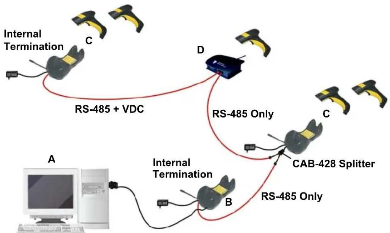
A. Host
B. BC-8060 Master cradle
C. BC-8060 Slave cradles
D. STARGATE™ base station
Example Multidrop STAR-System™ Network with BC-8060 as Master
In this layout a BC-8060 cradle acts as the Master. The Host is connected to the BC-8060 Master using any one of the multi-standard interfaces (RS-232, USB, WEDGE, or PEN Emulation). The Master is then connected to the slaves in the RS-485 network. In this way the slave cradles provide communications between a single Host and all readers in the system. STARGATE™ base stations can also be used as slaves in this network. The devices at the ends of the network must be terminated (see section 2.8.3).
See sections 4.6 and 4.7 or the original manufacturer's Datalogic Aladdin™ Help On-Line for system configuration specifications.
3.2.3 Master BC-8060 Network Troubleshooting
Two diagnostic strings can be sent via RS-232 from the Host to the Master cradle in order to have feedback about the network itself.
#+LSlave
Returns a list of all the Slaves recognized at boot up.
Example:
In a network where the Master cradle has address 0188 and one Slave cradle with address 0001, the response is:
188
1
#+Alive
Executes a continuous Alive request to the slave xxxx in order to monitor the performance of the connection. A diagnostic message is displayed on the Host.
Example:
If this command is sent for slave cradle with address 0032, the response is:
/*32: BC-80X0 SOFTWARE RELEASE 1.00 20/10/2006*/
if there are no communication errors
/*32: FAIL*/
if there are communication errors.
To exit from this command, reset the system by cycling power to the Master cradle.
4 CONFIGURATION
4.1 CONFIGURATION METHODS
4.1.1 Reading Configuration Bar Codes
This manual can be used for complete setup and configuration of your reader by following the setup procedures in this chapter (see section 4.2 for an overview).
If you wish to change the default settings, this manual provides complete configuration of your reader in an easy way.
To configure your reader:
1) Open the folded page in Appendix C with the hex-numeric table and keep it open during the device configuration.
2) Read the Enter Configuration code ONCE, available at the top of each page of configuration.
3) Modify the desired parameters in one or more sections following the procedures given for each group.
4) Read the Exit and Save Configuration code ONCE, available at the top of each page of configuration.
Reference notes describing the operation of the more complex parameters are given in chapter 5.
4.1.2 Using the Original Manufacturer's Datalogic Aladdin™
The original manufacturer's Datalogic Aladdin™ is a multi-platform utility program providing a quick and user-friendly configuration method via the RS-232/USB-COM interface.
It also allows upgrading the software of the connected device (see the original manufacturer's Datalogic Aladdin™ Help On-Line for more details).
4.1.3 Copy Command
A previously configured device (Master), can be used to send its configuration directly to other devices of the same type (Slaves). The particular procedure for each device is given in section 5.14.
4.1.4 Sending Configuration Strings from Host
An alternative configuration method is provided in Appendix A using the RS-232 interface. This method is particularly useful when many devices need to be configured with the same settings. Batch files containing the desired parameter settings can be prepared to configure devices quickly and easily.
4.2 SETUP PROCEDURES
For PowerScan ^® D8330 Series readers, follow the setup procedures in sections 4.3, and 4.8.
For PowerScan ^® M8300 Series readers, the setup procedures depend on two basic applications, Stand-alone or STAR-System ^™ .
Stand-alone applications allow communication with the Host by either the BC-80X0 cradle (section 4.5), or by the STAR-Modem™ radio modem (section 4.5.2).
STAR-System™ applications allow communication with the Host through an RS-485 network by the STARGATE™ RF base station or by the BC-8000 cradle (sections 4.6 and 4.7).
Proceed as shown in the following diagram:
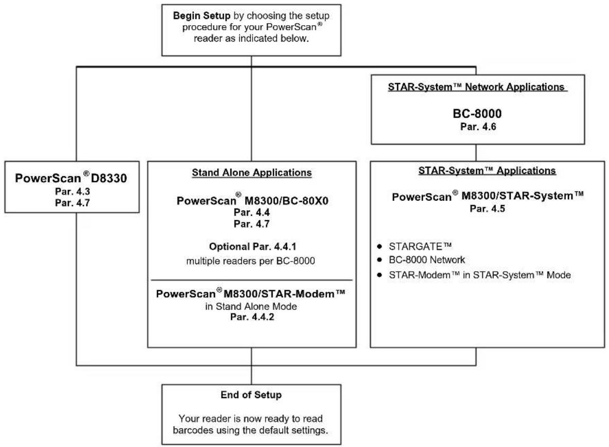
flowchart
graph TD
    A["Begin Setup by choosing the setup procedure for your PowerScan® reader as indicated below."] --> B["PowerScan® D8330<br>Par. 4.3<br>Par. 4.7"]
    A --> C["Stand Alone Applications<br>PowerScan® M8300/BC-80X0<br>Par. 4.4<br>Par. 4.7<br>Optional Par. 4.4.1<br>multiple readers per BC-8000"]
    A --> D["STAR-System™ Network Applications<br>BC-8000<br>Par. 4.6"]
    D --> E["STAR-System™ Applications<br>PowerScan® M8300/STAR-System™<br>Par. 4.5<br>• STARGATE™<br>• BC-8000 Network<br>• STAR-Modem™ in STAR-System™ Mode"]
    B --> F["End of Setup<br>Your reader is now ready to read barcodes using the default settings."]
    C --> F
    D --> F
4.3 POWERSCAN ^® D8330 SETUP
- Read the restore default parameters code below.
Restore PowerScan ^® D8330 Default
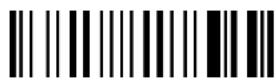
After reading the above code, go to section 4.8 Interface Selection.
4.4 POWERSCAN ^® M8300/BC-80X0 POINT-TO-POINT SETUP
A rapid configuration procedure has been devised for point-to-point applications where a single reader is associated exclusively with its own BC-80X0 base station and where it is not necessary to set the Date and Time parameters.
A special pre-printed bind-address label provided in the BC-80X0 base station package can be used to bind the PowerScan® M8300 reader to the base station with the address coded on the label. The address is also written numerically on the label to be easily recognized. Valid addresses are in the range from 0000 to 1999. Make sure that all cradles used in the same area have different addresses.
To rapidly configure your point-to-point application:
- Apply the bind-address label onto the BC-80X0 base station as indicated in the BC-80X0 Quick Reference Guide.
- When the BC-80X0 cradle is connected and powered, read the Bind-Address label to pair the PowerScan ^® M8300 to the BC-80X0 cradle.
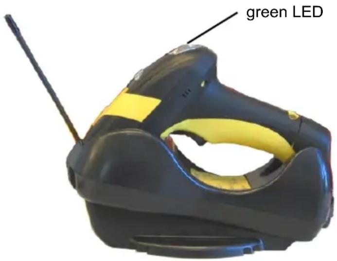
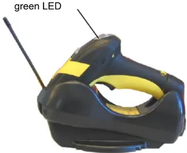
The green LED on the PowerScan ^® M8300 will blink: the reader is ready to be positioned onto the cradle.
- Firmly position the reader onto the cradle within 10 seconds, a beep will be emitted, signaling that the BC-80X0 cradle has been paired to the PowerScan ^® M8300, and the green LED on the reader will go off.
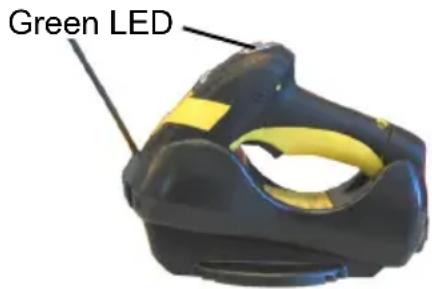
If it ever becomes necessary to change the reader, just read the bind-address label applied to the cradle and position the new reader onto the cradle.
Do not use multiple readers with this configuration method.
- Configure the BC-80X0 Cradle, refer to the "BC-80X0 Cradle Quick Reference Guide".
END of procedure. YOUR READER IS NOW READY TO READ CODES.
4.5 POWERSCAN ^® M8300/BC-80X0 STAND-ALONE SETUP
Read the restore default parameters code below.
- Restore PowerScan ^® M8300 Default

Follow the procedure below to set the radio address and bind PowerScan® M8300 to the BC-80X0 cradle.
- Enter Configuration

3 Set Date

six digits for Day, Month and Year (DDMMYY)
- Set Time
four digits for Hour and Minutes (HHMM)
5.
Set Radio Address

four digits for the PowerScan ^® M8300 Address (from 0000 to 1999).
All readers used in the same area must have different addresses.
6.
Exit and Save Configuration

- Read the Bind code to pair the PowerScan ^® M8300 to the BC-80X0 cradle. The reader is dedicated to the cradle. Any previously bound reader will be excluded.
To connect several readers to the same cradle see section 4.5.1, 'Using Multiple M8300 Series Readers with Same Cradle'.
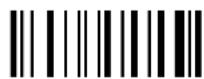
Bind

The green LED on the PowerScan ^® M8300 will blink; the reader is ready to be inserted into the cradle.
- Firmly insert the reader into the BC-80X0 cradle within 10 seconds, a beep will be emitted, signaling that the BC-80X0 cradle has been paired to the PowerScan ^® M8300, and the green LED on the reader will go off.
9. Read the BC-80X0 restore default code:
Restore BC-80X0 Default

Go to section 4.8 Interface Selection.
4.5.1 Using Multiple M-Series Readers with Same Cradle
If you want to use several M-Series readers with the same BC-80X0 cradle, you must first Bind the cradle with one of the readers (see previously described configuration procedure).
Successive readers can be associated with the same cradle by following the configuration procedure substituting the Bind command with Join (step 7).
7.
Join
The green LED on the PowerScan ^® M8300 will blink: the reader is ready to be positioned onto the cradle. Complete step 8.
END of procedure.

CAUTION
All readers associated with the same cradle must have different addresses.
YOUR READER IS NOW READY TO READ BAR CODES.
To change the defaults see section 4.10.
4.5.2 PowerScan ^ M8300/STAR-Modem ^TM in Stand-Alone Mode
To configure a PowerScan ^® M8300 reader to communicate with STAR-Modem ^™ in Stand-alone Mode, follow the procedure in section 4.5 substituting steps 6 and 7 with those below:
6.
STAR-Modem™ Address
Read the code above and the four-digit address of the STAR-Modem™.
7.
Exit and Save configuration

END of procedure.
YOUR READER IS NOW READY TO READ BAR CODES.
To change the defaults see section 4.10.
4.6 POWERSCAN ^® M8300/STAR-SYSTEM ^TM SETUP
The following procedure allows configuring a PowerScan ^® M8300 reader to communicate with various STAR-System ^™ devices such as STARGATE ^™ RF base stations.
1 Restore PowerScan ^® M8300 Default
- Enter Configuration
- Set Date

+ six digits for Day, Month and Year (DDMMYY)
- Set Time
+ four digits for Hour and Minutes (HHMM)
- Set the connection according to the length of the codes to be read:
Code Length ≤240 Characters

Code Length >240 Characters (not for systems with BC-8000 as Master)

6.
Set Radio Address

four digits from the Numeric Table in the range 0000-1999.
All readers must have different addresses.
7.
First STAR-System™ Address
Read the code above and the four-digit address of the First STAR-System™ device in the system.
8.
Set Last STAR-System™ Address
Read the code above and the four-digit address of the Last STAR-System™ device in the system.

NOTE
Whenever the system is composed of a single base station, the first and last base station addresses (steps 7 and 8) must have the same value.
9.
Exit and Save Configuration

END of procedure.
YOUR READER IS NOW READY TO READ BAR CODES.
To change the defaults see section 4.10.
4.7 BC-8060 STAR-SYSTEM™ NETWORK SETUP
When the BC-8060 cradle model is used in an RS-485 network, it must be initially configured. To do this using configuration bar codes, follow the procedure below using any PowerScan ^® M8300 reader.
1.
Set BC-8060 Address
+
four digits for the BC-8060 Address (from 0000 to 1999).
All cradles used in the network must have different addresses.
2.
Exit and Save configuration

- Read the Bind code to pair the PowerScan ^® M8300 to the BC-8060 cradle for configuration.
The green LED on the PowerScan ^® M8300 will blink; the reader is ready to be inserted into the cradle.
- Firmly insert the reader into the BC-8060 cradle within 10 seconds, a beep will be emitted, signaling that the BC-8060 cradle has been paired to the PowerScan® M8300, and the green LED on the reader will go off.
- Read the BC-8060 restore default code:
- Read the desired Enable Network code.
Enable RS-485 Master

Enable RS-485 Slave

END of procedure.
For Host Master Network Layouts (see section 3.2), The network configuration parameters can be changed through STAR-Link™ software running on the PC. Star-Link™ software can be downloaded for free from the original Manufacturer's web site: www.scanning.datalogic.com.
For BC-8060 Master Network Layouts (see section 3.2), The network configuration parameters can be changed either through the original manufacturer's Datalogic Aladdin™ configuration software running on the PC or by reading the bar code selections in the Network section of this manual starting on page 65. If using configuration bar codes, it is advised to completely configure the cradles before reconfiguring the PowerScan® M8300 reader (see below).

NOTE
After completing the BC-8060 cradle configuration and connections in the network, you must reconfigure the PowerScan ^® M8300 reader using the STAR-System ^™ procedure in section 4.6.
4.8 INTERFACE SELECTION
Read the interface selection code for your application.
RS-232
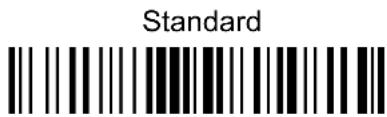
POS TERMINALS
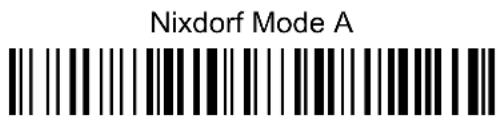
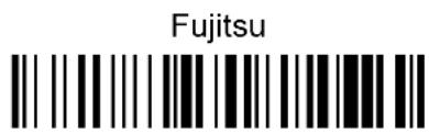
For POS terminal default settings refer to section 5.15.
WEDGE
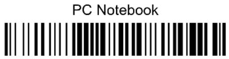
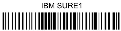
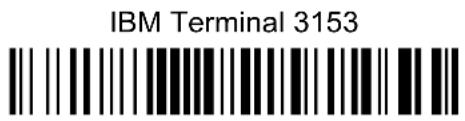
IBM Terminals 31xx, 32xx, 34xx, 37xx:
To select the interface for these IBM Terminals, read the correct KEY TRANSMISSION code. Select the KEYBOARD TYPE if necessary (default = advanced keyboard).
KEY TRANSMISSION MODE
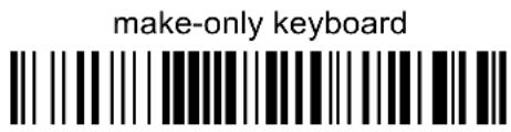
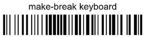
KEYBOARD TYPE
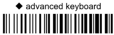
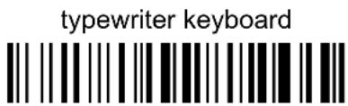
WEDGE (CONTINUED)
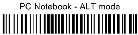
ALT MODE
The ALT-mode selection allows bar codes sent to the PC to be interpreted correctly independently from the Keyboard Nationality used. You do not need to make a Keyboard Nationality selection.
(default = Num Lock Unchanged). Make sure the Num Lock key on your keyboard is ON.
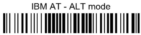
WYSE TERMINALS
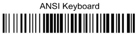
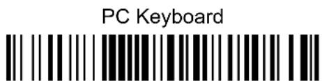
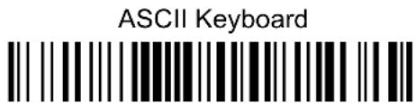
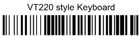
DIGITAL TERMINALS
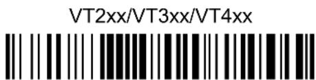
4.9 USB READER CONFIGURATION
The USB interface is available for PowerScan® D8330, BC-80X0 and C-8000 devices and is compatible with the following Operating Systems:
Windows ^® 98 (and later) IBM
® POS for Windows
Mac ^® OS 8.0 (and later) 4690 Operating System
USB Start-up
As with all USB devices, upon connection, the Host performs several checks by communicating with the device. During this phase normal operations are suspended (the LED on the PowerScan® D8330 reader blinks). Two basic conditions must be met before the device is ready, the correct USB driver must be loaded and sufficient power must be supplied to the reader.
① For all systems, the correct USB driver for the default USB-KBD interface is included in the Host Operating System and will either be loaded automatically or will be suggested by the O.S. and should therefore be selected from the dialog box (the first time only).
Normally the Host supplies sufficient power to the device and the start-up phase ends correctly. (The reader's LED stops blinking and the reader emits the beep OK signal).
In rare cases, if the Host does not supply sufficient power to the device, a dialog box will appear on the Host and the device will be blocked (the reader's LED continues blinking). In this case, disconnect the USB device cable at the Host (the reader's LED stops blinking), and then try a different USB port as indicated by the Operating System message. (The device emits the beep OK signal. You can now read codes).
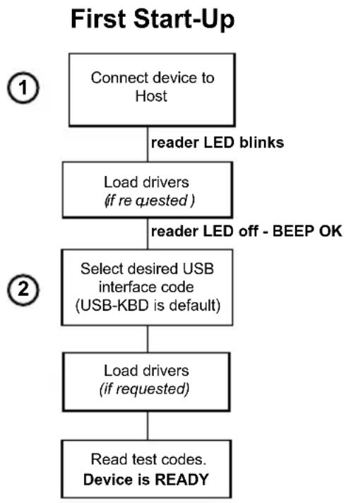
flowchart
graph TD
    A["Connect device to Host"] -->|reader LED blinks| B["Load drivers (if re quested)"]
    B -->|reader LED off - BEEP OK| C["Select desired USB interface code (USB-KBD is default)"]
    C --> D["Load drivers (if requested)"]
    D --> E["Read test codes. Device is READY"]
② At this point you can read the USB interface configuration code according to your application. Load drivers from the O.S. (if requested). When configuring the USB-COM interface, the relevant files and drivers must be installed from the USB Device Installation software, which can be downloaded from the original Manufacturer's web page at http://www.scanning.datalogic.com.
The device is ready. Successive start-ups will automatically recognize the previously loaded drivers.
USB
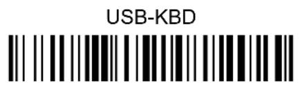
USB-KBD-ALT-MODE

USB-KBD-APPLE

USB-COM*

USB-IBM-Table Top

USB-IBM-Hand Held

* When configuring USB-COM, the relevant files and drivers must be installed from the USB Device Installation software, which can be downloaded from the original Manufacturer's web site at http://www.scanning.datalogic.com.
4.10 CHANGING DEFAULT SETTINGS
Once your reader is setup, you can change the default parameters to meet your application needs. Refer to the preceding paragraphs for initial configuration in order to set the default values and select the interface for your application.
In this manual, the configuration parameters are divided into logical groups making it easy to find the desired function based on its reference group.
The first four groups are for Standard Interface parameter configuration for all PowerScan ^® D8330 series readers and PowerScan ^® M8300/BC-80X0 Stand-alone configurations only:
RS-232
USB
WEDGE
PEN EMULATION
NETWORK PARAMETERS are available only for BC-8060 Network configurations.
The following parameter groups are common to all interface applications:
DATA FORMAT parameters regard the messages sent to the Host system for all interfaces except Pen Emulation.
POWER SAVE manages overall current consumption in the reading device.
READING PARAMETERS control various operating modes and indicator status functioning.
DECODING PARAMETERS maintain correct bar code decoding in certain special reading conditions.
CODE SELECTION parameters allow configuration of a personalized mix of codes, code families and their options.
ADVANCED FORMATTING PARAMETERS allow code concatenation and advanced formatting of messages towards the Host. It cannot be used with Pen Emulation connections.
RADIO PARAMETERS (M8300 series only) allow configuration of radio control parameters.
DISPLAY PARAMETERS (some M8300 series models only) allow configuration of reader display parameters.
RS-232 PARAMETERS
All PowerScan ^® D8330 Series readers + PowerScan ^® M8300/BC-80X0 configurations only
BAUD RATE
PARITY
DATA BITS
STOP BITS
HANDSHAKING
ACK/NACK PROTOCOL
FIFO
INTER-CHARACTER DELAY
RX TIMEOUT
- SERIAL TRIGGER LOCK
-
-
Read the Enter Configuration code ONCE, available at the top of each page.
-
Read configuration codes from the desired groups.
= Read the code and follow the procedure given
◆ = Default value
- Read the Exit and Save Configuration code ONCE, available at the top of each page.
BAUD RATE
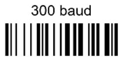
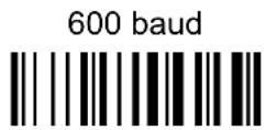
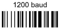
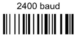
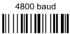
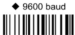
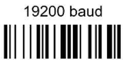
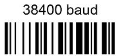
PARITY
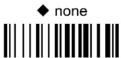
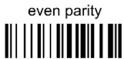
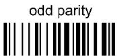
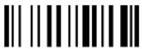
Enter Configuration Exit and Save Configuration
RS-232
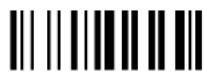
DATA BITS
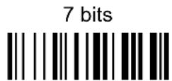
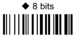
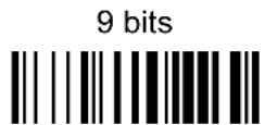
STOP BITS
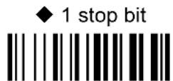
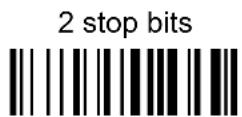
HANDSHAKING
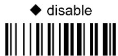
hardware (RTS/CTS)
software (XON/XOFF)
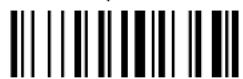

RTS always ON

See section 5.1.1 for details.
ACK/NACK PROTOCOL
◆ disable

enable

See section 5.1.2 for details, particularly on implementing this parameter with PowerScan ^® M8300.
FIFO
disable
◆ enable

See section 5.1.3 for details.
INTER-CHARACTER DELAY
delay between characters transmitted to Host
Read 2 numbers from the table where:
00 = DELAY disabled
01-99 = DELAY from 1 to 99 milliseconds
◆ delay disabled
Rx TIMEOUT
timeout control in reception from Host
Read 2 numbers from the table where:
00 = TIMEOUT disabled
01-99 = TIMEOUT from .1 to 9.9 seconds
◆ rx timeout 5 seconds
See section 5.1.4 for details.
SERIAL TRIGGER LOCK
◆ disabled
enable and select characters
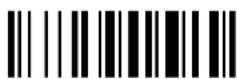
Read 2 characters from the Hex/Numeric table in the range 00-FE where:
- First Character enables device trigger
– Second Character inhibits device trigger until the first character is received again.
USB PARAMETERS
©
USB-COM
©
Handshaking, Ack/Nack protocol, FIFO, Inter-character delay, Rx timeout, Serial trigger lock
©
USB-KBD
©
Keyboard nationality, FIFO, Inter-character delay, Inter-code delay, USB keyboard speed
©
USB-IBM
©
No parameter selection required.
- Read the Enter Configuration code ONCE, available at the top of each page.
- Read configuration codes from the desired groups.
= Read the code and follow the procedure given
◆
= Default value
- Read the Exit and Save Configuration code ONCE, available at the top of each page.
HANDSHAKING
◆ disable

hardware (RTS/CTS)
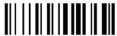
software (XON/XOFF)
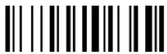
RTS always ON
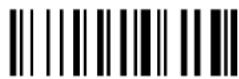
See section 5.1.1 for details.
ACK/NACK PROTOCOL
◆ disable

enable

See section 5.1.2 for details, particularly on implementing this parameter with PowerScan® M8300.
FIFO
disable
◆ enable

See section 5.1.3 for details.
INTER-CHARACTER DELAY
delay between characters transmitted to Host
Read 2 numbers from the table where:
00 = DELAY disabled
01-99 = DELAY from 1 to 99 milliseconds
◆ delay disabled
Rx TIMEOUT
timeout control in reception from Host
Read 2 numbers from the table where:
00 = TIMEOUT disabled
01-99 = TIMEOUT from .1 to 9.9 seconds
◆ rx timeout 5 seconds
See section 5.1.4 for details.
SERIAL TRIGGER LOCK
◆ disabled

enable and select characters
Read 2 characters from the Hex/Numeric table in the range 00-FE where:
- First Character enables device trigger
– Second Character inhibits device trigger until the first character is received again.
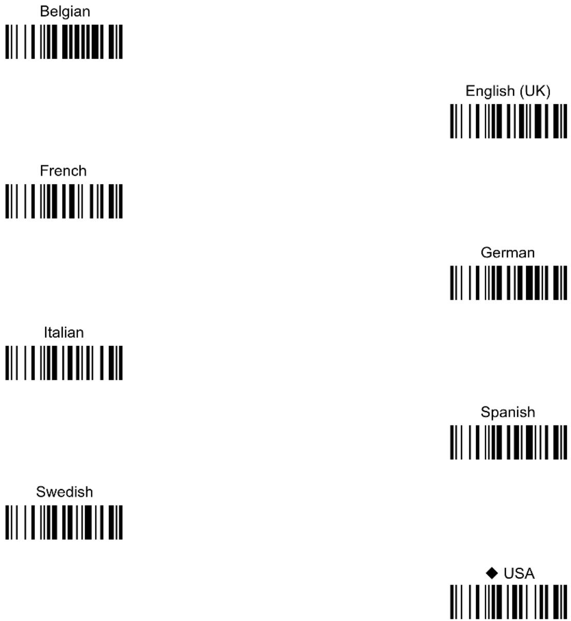
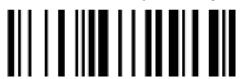
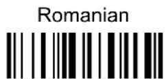
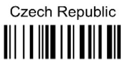
KEYBOARD NATIONALITY
Not Available for USB-KBD-ALT-MODE Interface
This parameter default value is restored through the Interface Selection code and not Restore Default.
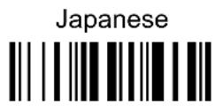
The Japanese and Eastern Block Keyboard Nationality selections are valid only for IBM AT compatible PCs.
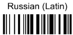
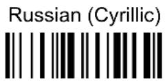
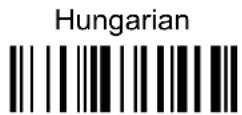
Slovenian, Croatian, Serbian (Latin)
FIFO
disable
◆ enable

See section 5.1.3 for details.
INTER-CHARACTER DELAY
delay between characters transmitted to Host
Read 2 numbers from the table where:
00 = DELAY disabled
01-99 = DELAY from 1 to 99 milliseconds
◆ delay disabled
INTER-CODE DELAY
delay between codes transmitted to Host

Read 2 numbers from the table where:
00 = DELAY disabled
01-99 = DELAY from 1 to 99 seconds
◆ delay disabled
USB KEYBOARD SPEED
Normal

Fast

WEDGE PARAMETERS
All PowerScan ^® D8330 Series readers + PowerScan ^® M8300/BC-80X0 configurations only
KEYBOARD NATIONALITY
CAPS LOCK
CAPS LOCK
AUTO-RECOGNITION
- Num Lock
-
INTER-CHARACTER DELAY
INTER-CODE DELAY
KEYBOARD SETTING
WEDGE CONTROL CHARACTER EMULATION
-
Read the Enter Configuration code ONCE, available at the top of each page.
-
Read configuration codes from the desired groups.
= Read the code and follow the procedure given
◆ = Default value
- Read the Exit and Save Configuration code ONCE, available at the top of each page.
KEYBOARD NATIONALITY
Belgian

English (UK)
French
German
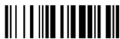
Italian
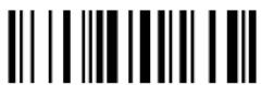
Spanish
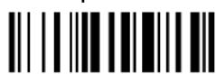
Swedish

◆ USA
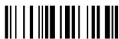
The Japanese and Eastern Block Keyboard Nationality selections are valid only for IBM AT compatible PCs.

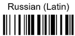
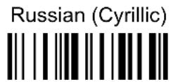
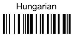

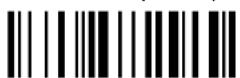

CAPS LOCK
Select the appropriate code to match your keyboard caps lock status.
Note: Caps lock manual configuration is ignored when Caps Lock Auto-Recognition is enabled.
For PC Notebook interface selections, the caps lock status is automatically recognized; therefore this command is not necessary.
CAPS LOCK AUTO-RECOGNITION (IBM AT COMPATIBLE ONLY)
disable
◆ enable

Num Lock
toggle num lock
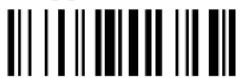
◆ num lock unchanged

This selection is used together with the Alt Mode interface selection for AT or Notebook PCs.
It changes the way the Alt Mode procedure is executed; therefore it should be set as follows:
- if your keyboard Num Lock is normally on use num lock unchanged
- if your keyboard Num Lock is normally off use toggle num lock
In this way the device will execute the Alt Mode procedure correctly for your application.
INTER-CHARACTER DELAY
delay between characters transmitted to Host
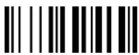
Read 2 numbers from the table where:
00 = DELAY disabled
01-99 = DELAY from 1 to 99 milliseconds
◆ delay disabled
INTER-CODE DELAY
delay between codes transmitted to Host
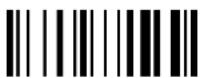
Read 2 numbers from the table where:
00 = DELAY disabled
01-99 = DELAY from 1 to 99 seconds
◆ delay disabled
KEYBOARD SETTING
ALPHANUMERIC KEYBOARD SETTING
The device (reader or cradle) can be used with terminals or PCs with various keyboard types and nationalities through a simple keyboard setting procedure.
The type of computer or terminal must be selected before activating the keyboard setting command.
Keyboard setting consists of communicating to the device how to send data corresponding to the keyboard used in the application. The keys must be set in a specific order.
Press and release a key to set it.
Some characters may require more than one key pressed simultaneously during normal use (refer to the manual of your PC or terminal for keyboard use). The exact sequence must be indicated to the reader in this case pressing and releasing the different keys.
Example:
If one has to press the "Shift" and "4" keys simultaneously on the keyboard to transmit the character "\" to the video, to set the "\", press and release "Shift" then press and release "4".
Each pressed and released key must generate an acoustic signal on the device; otherwise repress the key. Never press more than one key at the same time, even if this corresponds to the normal use of your keyboard.
Press "Backspace" to correct a wrong key entry. In this case the device emits 2 beeps.
Note: "CAPS LOCK" and "NUM LOCK" must be off before starting the keyboard setting procedure. "SHIFT" must be repressed for each character and cannot be substituted by "CAPS LOCK".
setting the alphanumeric keyboard

Read the code above.
Press the keys shown in the following table according to their numerical order.
WEDGE
Some ASCII characters may be missing as this depends on the type of keyboard: these are generally particular characters relative to the various national symbologies. In this case:
- The first 4 characters (Shift, Alt, Ctrl, and Backspace) can only be substituted with keys not used, or substituted with each other.
- characters can be substituted with other single symbols (e.g. "SPACE") even if not included in the bar code set used.
- characters can be substituted with others corresponding to your keyboard.
The device signals the end of the procedure with 2 beeps indicating the keys have been registered.
Do not place the reader onto the BC-80X0 cradle during this procedure. Otherwise, the battery charging will occur modifying the LEDs functioning.
CONTROL CHARACTER EMULATION
◆ Ctrl + Shift + Key
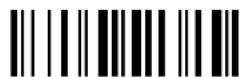
Ctrl + Key

PEN EMULATION
All PowerScan ^® D8330 Series readers + PowerScan ^® M8300/BC-80X0 configurations only
OPERATING MODE
MINIMUM OUTPUT PULSE
CONVERSION TO CODE 39
OVERFLOW
OUTPUT LEVEL
IDLE LEVEL
- INTER-BLOCK DELAY
-
- Read the Enter Configuration code ONCE, available at the top of each page.
- Read configuration codes from the desired groups.
◆ = Default value
- Read the Exit and Save Configuration code ONCE, available at the top of each page.
The operating mode parameters are complete commands and do not require reading the Enter and Exit configuration codes.
OPERATING MODE
◆ interpret mode

Interprets commands without sending them to the decoder.
transparent mode
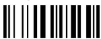
Sends commands to the decoder without interpreting them.
MINIMUM OUTPUT PULSE
high resolution code emulation
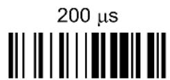
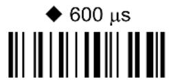
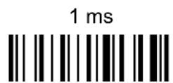
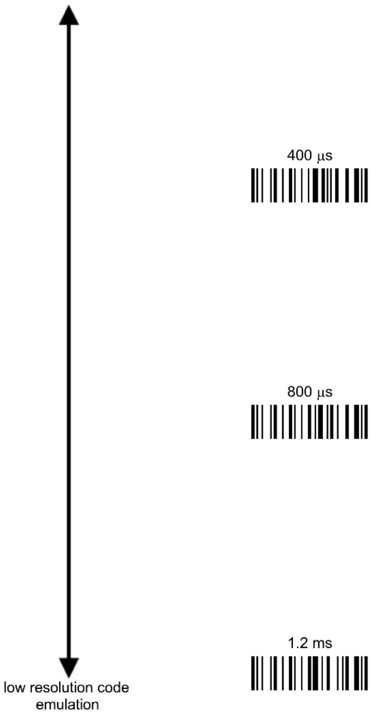
bar
| Resolution Level | Time (ms) | | ---------------- | --------- | | Low Resolution Code Emulation | 1.2 | | High Resolution Level | 400 | | Medium Resolution Level | 800 |See section 5.2.1 for details.
CONVERSION TO CODE 39 (D8330 SERIES ONLY)
◆ disable conversion to Code 39

Transmits codes in their original format.
enable conversion to Code 39

Converts codes read into Code 39 format.
See section 5.2.2 for details.
CONVERSION TO CODE 39 AND CODE 128 (M8300 SERIES ONLY)
◆ enable conversion to Code 39

Converts codes read into Code 39 format.
enable conversion to Code 128

Converts codes read into Code 128 format.
See section 5.2.2 for details.
OVERFLOW
narrow

◆ medium
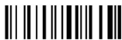
wide
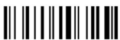
See section 5.2.3 for details.
OUTPUT LEVEL
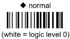
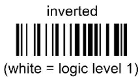
See section 5.2.4 for details.
IDLE LEVEL
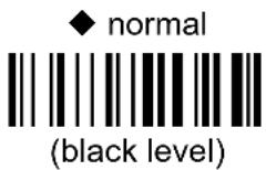
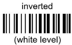
See section 5.2.4 for details.
INTER-BLOCK DELAY
delay between character blocks transmitted to Host
Read 2 numbers from the table where:
00 = DELAY disabled 01-99 = DELAY from .1 to 9.9 seconds
◆ delay disabled
See section 5.2.5 for details.
NETWORK PARAMETERS
BC-8060 model configurations only
RS-485 NETWORK
NETWORK BAUD RATE
◦ SLAVE ADDRESS RANGE ◎
NETWORK WARNING MESSAGE
RECEPTION WARNING MESSAGE
MASTER CRADLE HEADER
- MASTER CRADLE TERMINATOR
-
Read the Enter Configuration code ONCE, available at the top of each page.
-
Read configuration codes from the desired groups.
-
Read the Exit and Save Configuration code ONCE, available at the top of each page.
RS-485 NETWORK
◆ disable RS-485 network

enable RS-485 slave

enable RS-485 master

See section 3.2 for details.

NOTE
If a BC-8060 cradle is errantly configured as a Slave but not connected to a network, it may not be able to receive further commands from the reader. In this case it can be reconfigured by executing the bind procedure, which returns the cradle to Stand-alone configuration.
NETWORK BAUD RATE
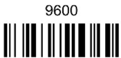
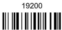
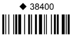
SLAVE ADDRESS RANGE
First Address

Read the code above and the four-digit address of the First Slave device in the system.
Last Address

Read the code above and the four-digit address of the Last Slave device in the system.
See section 5.3.1 for details.
NETWORK WARNING MESSAGE
◆ network warning
message not transmitted

network warning message transmitted

See section 5.3.2 for details.
RECEPTION WARNING MESSAGE
reception warning message not transmitted
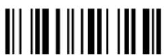
◆ reception warning message transmitted

See section 5.3.3 for details.
MASTER CRADLE HEADER
◆ no header

one character header
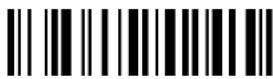
two character header

three character header

four character header

five character header

six character header
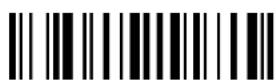
seven character header

eight character header

After selecting one of the desired Header codes, read the character(s) from the HEX table.
Valid characters are in the range: 00-FE
Example:

For more details about default and WEDGE Interface Extended Keyboard values, see sections 5.3.4, 5.4.1 and 5.4.2.
MASTER CRADLE TERMINATOR
◆ no terminator

one character terminator

two character terminator

three character terminator

four character terminator

five character terminator

six character terminator
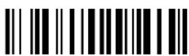
seven character terminator

eight character terminator

After selecting one of the desired Terminator codes, read the character(s) from the HEX table.
Valid characters are in the range: 00-FE
Example:

For more details about default and WEDGE Interface Extended Keyboard values, see sections 5.3.4, 5.4.1 and 5.4.2.
DATA FORMAT
NOT FOR PEN INTERFACES
CODE IDENTIFIER
CUSTOM CODE IDENTIFIER
HEADER
TERMINATOR
SPECIAL KEYS
FIELD ADJUSTMENT
FIELD ADJ. CHARACTER
CODE LENGTH TX
CHARACTER REPLACEMENT
ADDRESS STAMPING
ADDRESS DELIMITER
TIME STAMPING
TIME DELIMITER
- Read the Enter Configuration code ONCE, available at the top of each page.
- Read configuration codes from the desired groups.
= Read the code and follow the procedure given
◆ = Default value
- Read the Exit and Save Configuration code ONCE, available at the top of each page.
DATA FORMAT
| CODE IDENTIFIER TABLE | |||
| CODE | AIM STANDARD | MANUFACTURER STANDARD | Custom |
| 2/5 interleaved ]I y N | |||
| 2/5 industrial ]X y P | |||
| 2/5 normal 5 bars ]S y O | |||
| 2/5 matrix 3 bars ]X y Q | |||
| EAN 8 ]E 4 A | |||
| EAN 13 ]E 0 B | |||
| UPC A ]X y C | |||
| UPC E ]X y D | |||
| EAN 8 with 2 ADD ON ]E 5 J | |||
| EAN 8 with 5 ADD ON ]E 6 K | |||
| EAN 13 with 2 ADD ON | ]E 1 L | ||
| EAN 13 with 5 ADD ON | ]E 2 | M | |
| UPC A with 2 ADD ON | ]X y F | ||
| UPC A with 5 ADD ON | ]X y G | ||
| UPC E with 2 ADD ON | ]X y H | ||
| UPC E with 5 ADD ON | ]X y | I | |
| Code 39 | ]A y V | ||
| Code 39 Full ASCII | ]A y | W | |
| CODABAR | ]F y | R | |
| ABC CODABAR | ]X y S | ||
| Code 128 | ]C y T | ||
| EAN 128 | ]C y k | ||
| ISBT 128 | ]C4 | f | |
| Code 93 | ]G y U | ||
| CIP/39 | ]X y | Y | |
| CIP/HR | ]X y | e | |
| Code 32 | ]X y X | ||
| MSI | ]M y | Z | |
| Code 11 | ]H y b | ||
| Code 16K | ]K 0 p | ||
| Code 49 | ]T y q | ||
| GS1 DataBarTM Expanded Linear and Stacked | ]e 0 | t | |
| GS1 DataBar Limited | ]e 0 | v | |
| GS1 DataBar 14 Linear and Stacked | ]e 0 u | ||
- AIM standard identifiers are not defined for all codes: the X identifier is assigned to the code for which the standard is not defined. The y value depends on the selected options (check digit tested or not, check digit tx or not, etc.).
- When customizing the Manufacturer Standard code identifiers, 1 or 2 identifier characters can be defined for each code type. If only 1 identifier character is required, the second character must be selected as FF (disabled).
- The code identifier can be singly disabled for any code by simply selecting FF as the first identifier character.
• Write in the Custom character identifiers in the table above for your records.
CODE IDENTIFIER
◆ disable

Manufacturer Standard

AIM standard
custom

CUSTOM CODE IDENTIFIER
define custom code identifier(s)

① Read the above code.
(Code Identifiers default to Manufacturer Standard, see table on previous page).
② Select the code type from the code table in Appendix B for the identifier you want to change.
③ You can define 1 or 2 identifier characters for each code type. If only 1 identifier character is required, the second character must be selected as FF (disabled). Read the hexadecimal value corresponding to the character(s) you want to define as identifiers for the code selected in step ②: valid characters are in the range 00-FD.
Example: To define Code 39 Code Identifier = @
Read
define custom code identifier(s)
+
Code 39

+ 40 + FF
HEADER
no header

one character header

two character header

three character header
four character header

five character header

six character header

seven character header
eight character header

After selecting one of the desired Header codes, read the character(s) from the HEX table. Valid characters are in the range 00-FE. For Wedge and USB-KBD interfaces, it is also possible to read the Special Key(s) on page 75.
Example:
four character header

+ 41 + 42 + 43 + 44 = Header ABCD
For more details see sections 5.4.1 and 5.4.2.
TERMINATOR
no terminator

one character terminator

two character terminator
three character terminator
four character terminator

five character terminator

six character terminator

seven character terminator
eight character terminator

After selecting one of the desired Header codes, read the character(s) from the HEX table. Valid characters are in the range 00-FE. For Wedge and USB-KBD interfaces, it is also possible to read the Special Key(s) on page 75.
Example:
two character terminator

For more details see sections 5.4.1 and 5.4.2.
SPECIAL KEYS
Available only for Wedge IBM AT-PS/2 and USB-KBD Interfaces

NOTE
It is necessary to define each Special Key by following the procedure given in section 5.4.2.
Select one or more of the following Special Keys according to your needs.
Special Key 1

Special Key 2
Special Key 3

Special Key 4

Special Key 5

FIELD ADJUSTMENT
◆ disable field adjustment

Field adjustment allows a number of characters n, to be added to or subtracted from the bar code read. The adjustment can be different for each enabled code type. To define the field adjustment:
① Read the enable field adjustment code:
enable field adjustment

② Select the code type from the Code Identifier Table in Appendix B.
③ Select the type of adjustment to perform:
right addition

left addition
right deletion

left deletion

④ Read a number in the range 01 - 32 from the Hex/Numeric Table to define how many characters to add or delete:
Conditions:
- Adjustment is only performed on the bar code data, the Code Identifier and Code Length Transmission fields are not modified by the field adjustment parameter.
- If the field setting would subtract more characters than exist in the bar code, the subtraction will take place only to code length 0.
- You can set up to a maximum of 10 different field adjustments on the same bar code family or on different bar code families.
Example: To add 4 characters to the right of Standard Code 39 Codes:

FIELD ADJUSTMENT CHARACTER
① Read the field adjustment character code:
field adjustment character

② Read the hexadecimal value corresponding to the character you want to use for field adjustment. Valid characters are in the range 00-FE. For Wedge and USB-KBD interfaces, it is also possible to read the Special Key(s) on page 75.
Example:
To define the field adjustment character = A:
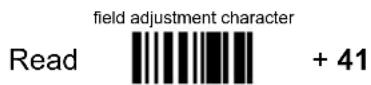
CODE LENGTH TX
◆ code length not transmitted

code length transmitted in variable-digit format

code length transmitted in fixed 4-digit format

The code length is transmitted in the message after the Headers and Code Identifier characters. The code length is calculated after performing any field adjustment operations.
CHARACTER REPLACEMENT
◆ disable character replacement
This parameter allows up to three characters to be replaced from the bar code read. These substitutions are stored in memory. To define each character replacement:
① Read one of the following character replacement codes:
first
character replacement
second character replacement

third
character

② From the Code Identifier Table in Appendix B, read the Code Identifier for the desired code family.
0 = character replacement will be effective for all code families.
③ From the Hex/Numeric Table read two characters corresponding to the Hex value (00-FE), which identifies the character to be replaced. For Wedge and USB-KBD interfaces, it is also possible to read the Special Key(s) on page 75.
④ From the Hex/Numeric Table read two characters corresponding to the Hex value (00-FE), which identifies the new character to replace. For Wedge and USB-KBD interfaces, it is also possible to read the Special Key(s) on page 75.
FF = the character to be replaced will be substituted with no character, that is, it will be removed from the code.
Example:
The following strings define:
- First Character Replacement: substitution in Code 39 bar codes of all occurrences of the 0 character with the 1 character.
- Second Character Replacement: substitution in Code 39 bar codes of all occurrences of the A character with the B character.
first character replacement
Code 39
ASCII characters corresponding to the HEX value for character 0
ASCII characters corresponding to the HEX value for character 1
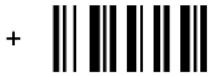
+ 30 + 31
For Code 39 codes containing the string "0123", the contents transmitted will be "1123".
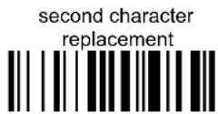
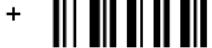
+ 41 + 42
ASCII characters corresponding to the HEX value for character A
ASCII characters corresponding to the HEX value for character B
For Code 39 codes containing the string "ABCD", the contents transmitted will be "BBCD".
ADDRESS STAMPING (M8300 SERIES ONLY)
◆ disable reader address stamping

enable reader address stamping

◆ disable cradle address stamping

enable cradle address stamping

See section 5.4.3 for details.
ADDRESS DELIMITER (M8300 SERIES ONLY)
◆ disable reader address delimiter

enable reader address delimiter and select characters

◆ disable cradle address delimiter

enable cradle address delimiter and select characters

Read 2 HEX characters in the range 00-FE.
Read 2 HEX characters in the range 00-FE.
See section 5.4.4 for details.
TIME STAMPING (M8300 SERIES ONLY)
◆ disable
hour/minutes/seconds
month/day/year

hour/minutes/seconds
day/month/year
hour/minutes/seconds

month/day/year

day/month/year

See section 5.4.5 for details.
TIME STAMPING DELIMITER (M8300 SERIES ONLY)
◆ disable
select delimiter

Read 2 HEX characters in the range 00-FE.
See section 5.4.6 for details.
POWER SAVE
SLEEP STATE
ENTER SLEEP TIMEOUT
- Read the Enter Configuration code ONCE, available at the top of each page.
- Read configuration codes from the desired groups.
= Read the code and follow the procedure given
◆ = Default value
- Read the Exit and Save Configuration code ONCE, available at the top of each page.
SLEEP STATE
◆ disable

enable

See section 5.5.1 for details.
For M8300 series readers, sleep state is entered immediately after reading a code and is not configurable.
ENTER SLEEP TIMEOUT
enter sleep timeout

Read 2 numbers in the range 00-99:
00 = Enter Sleep state immediately
01-99 = corresponds to a max. 9.9 sec. delay before entering the Sleep state.
◆ enter sleep timeout = 0.6 sec.
See section 5.5.2 for details.
READING PARAMETERS
- TRIGGER TYPE
- TRIGGER SIGNAL
TRIGGER CLICK
- TRIGGER-OFF TIMEOUT
-
FLASH MODE
- READS PER CYCLE
-
◎ SAFETY TIME ◎
BEEPER INTENSITY
BEEPER TONE
BEEPER TYPE
BEEPERLENGTH
Good Read Spot Duration
AIMING SYSTEM
CRADLE BEEPER INTENSITY
- Read the Enter Configuration code ONCE, available at the top of each page.
- Read configuration codes from the desired groups.
= Read the code and follow the procedure given
◆ = Default value
- Read the Exit and Save Configuration code ONCE, available at the top of each page.
TRIGGER TYPE
◆ hardware trigger

Restores TRIGGER MODE
software trigger

Enables FLASH MODE
always on

TRIGGER SIGNAL
◆ trigger active level

trigger active pulse
See section 5.6.1 for details.
TRIGGER CLICK
◆ disable
enable

See section 5.6.2 for details.
TRIGGER-OFF TIMEOUT
trigger-off timeout

Read 2 numbers in the range 00-99:
00 = disables the trigger-off timeout
01-99 = corresponds to a max. 99-sec. delay after the trigger
press to allow the reader to turn off automatically.
◆ trigger-off timeout disabled
See section 5.6.3 for details.
FLASH MODE
"FLASH" ON duration

"FLASH" OFF duration

Read 2 numbers in the range 01-99:
01 to 99 = from .1 to 9.9 seconds.
◆ Flash-ON = 1 sec. Flash-OFF = 0.6 sec
READS PER CYCLE
◆ one read per cycle

multiple reads per cycle

See section 5.6.4 for details.
SAFETY TIME
safety time

Limits same code consecutive reading.
Read 2 numbers in the range 00-99:
00 = no same code consecutive reading until reader is removed (no decoding) for at least 400 ms.
01-99 = timeout from .1 to 9.9 seconds before a consecutive read on same code.
◆ safety time = 0.5 sec
See section 5.6.5 for details.
BEEPER INTENSITY
* very low intensity

low intensity
medium intensity

◆ high intensity

* This sets the beeper OFF for data entry, while for all other beeper signals it has the meaning “very low intensity”. The Beeper Intensity parameter is effective for all operating conditions described in section 7.5.
BEEPER TONE
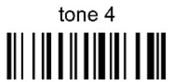
BEEPER TYPE
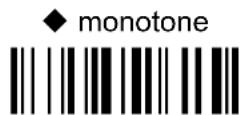
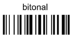
BEEPER LENGTH
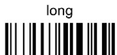
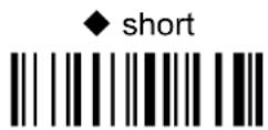
- Read the Enter Configuration code ONCE, available at the top of each page.
- Read configuration codes from the desired groups.
◆ = Default value
- Read the Exit and Save Configuration code ONCE, available at the top of each page.
INK SPREAD
disable

◆ enable

See section 5.7.1 for details.
OVERFLOW CONTROL
disable
◆ enable

See section 5.7.2 for details.
INTERDIGIT CONTROL
disable

◆ enable

See section 5.7.3 for details.
DECODING SAFETY
◆ one read
(decoding safety disabled)
two reads
three reads
four reads
Required number of good reads before accepting code.
enable

In the case of damaged or poorly printed codes, this parameter allows reading multiple parts of the single code to reconstruct it.
To read codes using this technology, simply move the illuminated bar over the code so that each line of the code is scanned. During this process a series of brief “ticks” indicates that reading is proceeding correctly.
Conditions:
- This parameter is only valid for the following codes:
| EAN 8 without Add-on | EAN 13 without Add-on | UPC A without Add-on |
| Code 128 Code 39 | ||
- For Code 39, Check digit control is forced.
- PuzzleSolver™ is not valid for ISBT 128 code.
CODE SELECTION
AUTO-CONFIGURATION
EAN/UPC FAMILY
2/5 FAMILY
CODE 39 FAMILY
CODE 128 FAMILY
⊙ CODABAR FAMILY ⊙
CODE 93
MSI
CODE 11
CODE 16K
CODE 49
GS1 DATABAR CODES
- Read the Enter Configuration code ONCE, available at the top of each page.
- Read configuration codes from the desired groups.
= Read the code and follow the procedure given
◆ = Default value
- Read the Exit and Save Configuration code ONCE, available at the top of each page.
Code selections may be performed according to two different procedures:
- Auto-configuration, allowing an automatic recognition and selection of the code families to be read;
- Manual configuration, requiring configuration and selection of each code family to be read.
AUTO-CONFIGURATION
The following codes do not require reading the Enter and Exit configuration codes.
In auto-configuration mode the reader enters a particular state, during which it reads, recognizes and saves all information received from the decoding of an existing code (with the exception of MSI, Code 49 and Code 16k code types). In this way, the code families will be automatically configured.
It is possible to configure up to 10 code types, whose length is variable and check digit ignored. If reading different codes belonging to the same family, information about the last code will overwrite the information about the previous one.
Follow the given procedure to auto-configure the desired code families:

CAUTION
If no code is read during the auto-configuration procedure (step ②), the configuration will be empty and therefore the reader will be unable to read codes.
① Read the following code to enter the auto-configuration mode:
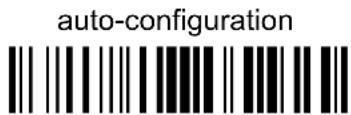
② Read an existing code belonging to the code families that you need to configure.
③ Read the following code to save the configuration automatically and return to the reader's normal functioning:
save auto-configuration
If you need to change the configuration, repeat the auto-configuration procedure, follow the manual configuration by setting the parameters for each single code family or read the "Restore Default" code on page 165. Be careful that in the latter case all reader parameters will be restored.
DISABLE ALL CODE FAMILIES


NOTE
The reader allows up to 10 code selections. This does not limit the number of CODES enabled to 10, as it depends on the code family.
SINGLE SELECTIONS =
• ONE combination code from the EAN family
- ONE code from the 2/5 family
Example
5 code selections: 1. 2/5 Interleaved
- 2/5 Industrial
- Code 128 + EAN 128
- Code 39 Full ASCII + Code 32
- UPC A/UPC E ____
- etc.
In this section all SINGLE code selections are underlined and in bold.
EAN/UPC FAMILY
disable the family

① Read the desired family code
Note:
Since the EAN/UPC without ADD ON code selection is enabled by default, to correctly enable another selection, first disable the family.
EAN 8/EAN 13/UPC A/UPC E with and without ADD ON

WITHOUT ADD ON
◆ EAN 8/EAN 13/UPC A/UPC E

EAN 8/EAN 13
UPC A/UPC E

WITH ADD ON 2 AND 5
EAN 8/EAN 13/UPC A/UPC E
EAN 8/EAN 13
UPC A/UPC E

WITH ADD ON 2 ONLY
EAN 8/EAN 13

UPC A/UPC E

WITH ADD ON 5 ONLY
EAN 8/EAN 13

UPC A/UPC E
WITH AND WITHOUT ADD ON
◆ EAN/UPC with and without ADD ON no
Autodiscrimination

EAN/UPC Autodiscrimination ADD ON by
Prefix

By setting the EAN/UPC Autodiscrimination ADD ON by Prefix, the desired prefixes must be selected by reading the corresponding codes given in the following section, since no prefix is configured by default.
SELECT EAN/UPC PREFIXES

NOTE
When scanning the following codes, bar codes starting with the selected prefixes will be read and transmitted only if the ADD ON is present. If no ADD ON is found, the bar code will not be read. Bar codes starting with different characters are read regardless of ADD ON presence and transmitted always without ADD ON.
◆ Cancel All Selections
OR
select one or more of the following prefixes:
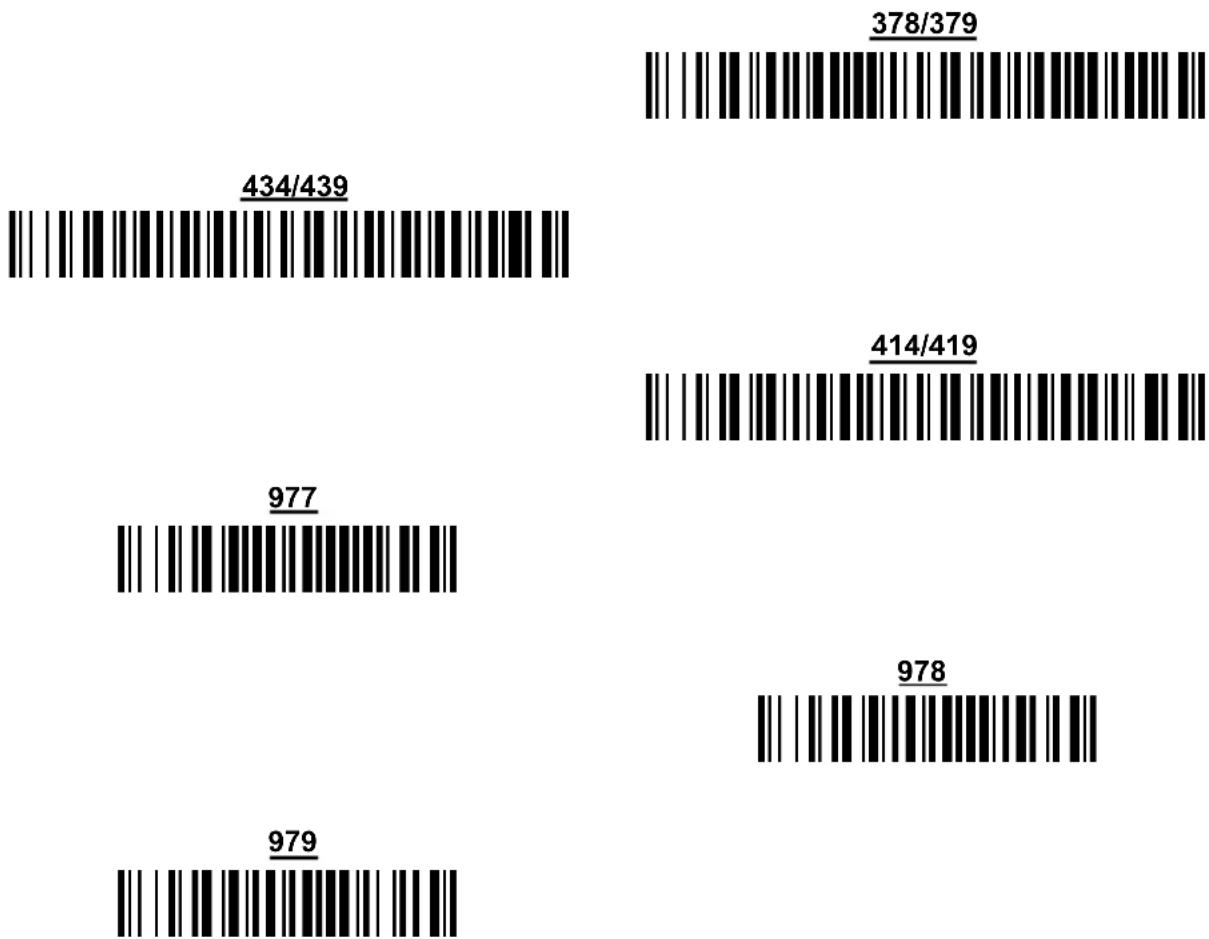
bar
| Label | Value | | --------- | ------- | | 434/439 | | | 977 | | | 979 | | | 378/379 | | | 414/419 | | | 978 | |The commands above are not mutually exclusive. They can be used to configure more than one set of prefixes simultaneously.
Example:
The following string allows reading and transmitting with ADD ON all EAN/UPC starting with the 434/439, 977 and 978 prefixes:
- EAN/UPC Autodiscrimination ADD ON by Prefix.
- 434/439: enables reading and transmission with ADD ON of all EAN/UPC bar codes starting with 434/439 prefixes.
- 977: enables reading and transmission with ADD ON of all EAN/UPC bar codes starting with 977 prefix.
- 978: enables reading and transmission with ADD ON of all EAN/UPC bar codes starting with 978 prefix.
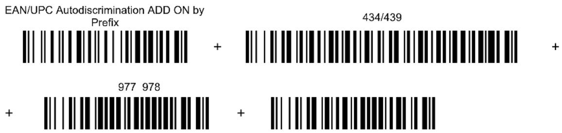
bar
| Prefix | Value | |--------|-----------| | | 434/439 | | | + | | | 977 978 | | | + |To clear the current prefix selections:
- Cancel all Selections
EAN/UPC CHECK DIGIT TX SELECTIONS
For each code type in this family you can choose to transmit the check digit or not
CHECK DIGIT TRANSMISSION
NO CHECK DIGIT
TRANSMISSION
CONVERSION OPTIONS
UPC E to UPC A conversion

UPC E to EAN 13 conversion

UPC A to EAN 13 conversion

EAN 8 to EAN 13 conversion

Enable only ISBN conversion

Enable only ISSN conversion

Enable both ISBN and ISSN conversion

Disable both ISBN and ISSN conversion
2/5 FAMILY
disable the family

① Read the desired family code
◆ Interleaved 2/5
Normal 2/5 (5 Bars)
Industrial 2/5 (IATA)
Matrix 2/5 (3 Bars)
The pharmaceutical code below is part of the 2/5 family but has no check digit or code length selections.
Code CIP/HR

French pharmaceutical code
② Read a check digit selection
CHECK DIGIT TABLE
no check digit control
◆ check digit control and transmission

check digit control without transmission
③ Read 4 numbers for the code length where:
- First 2 digits = minimum code length.
- Second 2 digits = maximum code length.
The maximum code length is 99 characters.
The minimum code length must always be less than or equal to the maximum.
Examples:
0199 = variable from 1 to 99 digits in the code.
1010 = 10 digit code length only.
CODE 39 FAMILY
disables the family

① Read the desired family code
② Read a check digit selection
CHECK DIGIT TABLE
◆ Standard Code 39

◆ no check digit control

Full ASCII Code 39

check digit control
and transmission
check digit control
without transmission

The pharmaceutical codes below are part of the Code 39 family but have no check digit selections.
Code CIP39

French pharmaceutical code
Code 32

Italian pharmaceutical code
CODE LENGTH (optional)
The code length selection is valid for the entire Code 39 family
Read the code + 4 numbers for the code length where:
First 2 digits = minimum code length.
Second 2 digits = maximum code length.
set code length

The maximum code length is 99 characters.
The minimum code length must always be less than or equal to the maximum.
Examples: 0199 = variable from 1 to 99 digits in the code. 1010 = 10 digit code length only.
CODE 128 FAMILY
disable the family
① Read the desired family code
◆ Code 128
control without transmission of check digit
EAN 128

control without transmission of check digit
ISBT 128
enabling ISBT 128 automatically disables Puzzle Solver™.
Transmit GS Before Code
Code EAN 128 uses the ASCII
◆ disable
enable
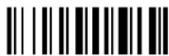
If the
CODE LENGTH (optional)
The code length selection is valid for the entire Code 128 family and is calculated on the output string.
Read the code + 4 numbers for the code length where:
set code length
First 2 digits = minimum code length.
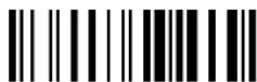
Second 2 digits = maximum code length.
The maximum code length is 99 characters.
The minimum code length must always be less than or equal to the maximum.
Examples: 0199 = variable from 1 to 99 digits in the code. 1010 = 10 digit code length only.
CODE 93
◆ disable the code

Code 93

control without transmission of check digit
CODABAR FAMILY
◆ disable the family

① Read the desired equality control code
② Read a start/stop transmission selection
Standard Codabar

no start/stop character equality control
Standard Codabar

start/stop character equality control
START/STOP CHARACTER
TRANSMISSION
no transmission

transmission
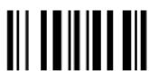
The Codabar ABC code below uses a fixed start/stop character transmission selection.
Codabar ABC
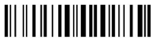
no start/stop character equality control but transmission.
Codabar ABC Forced Concatenation
enable Codabar ABC with forced concatenation

non start/stop character equality control but transmission
CODE LENGTH (optional)
The code length selection is valid for the entire Codabar family
Read the code + 4 numbers for the code length where:
set code length
First 2 digits = minimum code length.
Second 2 digits = maximum code length.

The maximum code length is 99 characters.
The minimum code length must always be less than or equal to the maximum.
Examples: 0199 = variable from 1 to 99 digits in the code. 1010 = 10 digit code length only.
START/STOP CHARACTER CASE IN TRANSMISSION
The start/stop character case selections below are valid for the entire Codabar family:
transmit start/stop characters in lower case
transmit start/stop characters in upper case

MSI
◆ disable the family

Enable the code by selecting one of the check digit selections.
no check digit control

MOD10 check digit control no check digit transmission

MOD10 check digit control check digit transmission

MOD11 - MOD10 check digit control no check digit transmission

MOD11 - MOD10 check digit control check digit transmission

MOD10 - MOD10 check digit control no check digit transmission

MOD10 - MOD10 check digit control check digit transmission

CODE 11
◆ disable the family

Enable the code by selecting one of the check digit selections.
no check digit control

Type C check digit control check digit transmitted
Type C check digit control check digit not transmitted

Type K check digit control check digit transmitted

Type K check digit control check digit not transmitted

Type C and Type K check digit control check digits transmitted

Type C and Type K check digit control check digits not transmitted

CODE 16K
◆ disable the code

Code 16K

To read stacked codes, simply move the reader over the code so that each line of the code is scanned. During this process a series of brief “ticks” indicates that reading is proceeding correctly.
CODE 49
◆ disable the code

Code 49

To read stacked codes, simply move the reader over the code so that each line of the code is scanned. During this process a series of brief “ticks” indicates that reading is proceeding correctly.
GS1 DATABAR ^TM CODES
◆ disable the family

DISABLE CODE
disable GS1 DataBar Expanded Linear and Stacked
disable GS1 DataBar Limited

disable GS1 DataBar 14 Linear and Stacked

ENABLE CODE
enable GS1 DataBar Expanded Linear and Stacked

enable GS1 DataBar Limited
enable GS1 DataBar 14 Linear and Stacked

To read stacked codes, simply move the reader over the code so that each line of the code is scanned. During this process a series of brief “ticks” indicates that reading is proceeding correctly.
ADVANCED FORMATTING
NOT FOR PEN INTERFACES
CONCATENATION
ADVANCED FORMATTING

NOTE
Please follow the setup procedure carefully for these parameters.

NOTE
The Advanced Formatting parameters may not be compatible with the IBM USB POS interface selection.
- Read the Enter Configuration code ONCE, available at the top of page.
- Read configuration codes precisely following the numbered procedure given.
= Read the code and follow the procedure given
◆ = Default value
- Read the Exit and Save Configuration code ONCE, available at the top of page.
CONCATENATION
Permits the concatenation of two codes defined by code type and length. It is possible to set a timeout for the second code reading and to define code transmission if the timeout expires.
The order of transmission is CODE 1-CODE 2.
Define Concatenation
1
Code 1
Read the code type from the Code Identifier Table beginning in Appendix B.
Read a number in the range 01-99 from the Hex/Numeric Table.
2
Code 2
code ID

Read the code type from the Code Identifier Table beginning in Appendix B.
code length

Read a number in the range 01-99 from the Hex/Numeric Table.
3
Concatenation Result Code ID
use code 1 ID

use code 2 ID
Since you can concatenate codes from different families, you must select the Code ID character of the resulting code. The Code ID character will be sent in the output message only if it is enabled according to the Code Identifier selection (Manufacturer, AIM, or Custom).
4
Concatenation Timeout
timeout

Read two numbers in the range 00 to 99
00= no timeout
01-99 = timeout from 1 to 99 seconds
Define the timeout, which determines the valid waiting period between the two codes, in order to accept concatenation. If the timeout expires, the resulting action will be based on the following selection. (HHDII)
5
Transmission after Timeout
no code transmitted after timeout
only code 1 transmitted (if read) after timeout

only code 2 transmitted (if read) after timeout

either code 1 or code 2 transmitted after timeout

ADVANCED FORMATTING
Advanced formatting has been designed to offer you complete flexibility in changing the format of bar code data before transmitting it to the host system. This formatting will be performed when the bar code data meets certain criteria, which you will define in the following procedure.
Up to 4 advanced code management formats can be defined and saved in memory. For each format you must complete the entire configuration procedure:
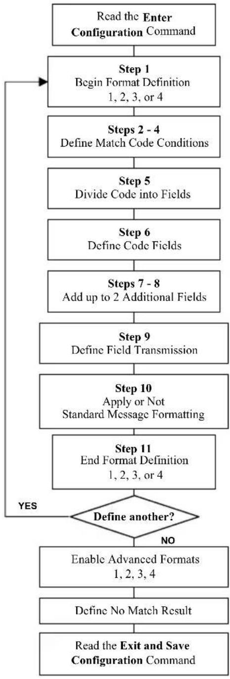
flowchart
graph TD
    A["Read the Enter Configuration Command"] --> B["Step 1 Begin Format Definition 1, 2, 3, or 4"]
    B --> C["Steps 2 - 4 Define Match Code Conditions"]
    C --> D["Step 5 Divide Code into Fields"]
    D --> E["Step 6 Define Code Fields"]
    E --> F["Steps 7 - 8 Add up to 2 Additional Fields"]
    F --> G["Step 9 Define Field Transmission"]
    G --> H["Step 10 Apply or Not Standard Message Formatting"]
    H --> I["Step 11 End Format Definition 1, 2, 3, or 4"]
    I --> J{Define another?}
    J -->|YES| B
    J -->|NO| K["Enable Advanced Formats 1, 2, 3, 4"]
    K --> L["Define No Match Result"]
    L --> M["Read the Exit and Save Configuration Command"]
1 Begin Format Definition
begin Format 1 definition

begin Format 2 definition

begin Format 3 definition

begin Format 4 definition
2
Match
Code
match code type

Read the above code + the code type to match from the Code Identifier Table in Appendix B.
OR
any code type

3
Match
Code
match code length

Read the above code + two numbers in the range 01 to 99 for the exact code length.
OR
any code length

4
Match with Predefined Characters
match with 1 character
match with a 2-character string
match with a 3-character string

match with a 4-character string

After selecting the predefined match code, read the character(s) from the HEX table. Range of characters = 00-FE.
Example:
Match code with the 2-character predefined string = "@@".
Read
Match with a 2-character string

+ 40 + 40
AND position of first character in predefined string

Read the above code + two numbers in the range 01 to 99 representing the character position in the code where the first character of the predefined string must be found.
Read 00 if the match string can be found in any character position.
See section 5.8.1 for details.
5
Divide Code into Fields
divide code into fields

Read one number in the range 1 to 5 to divide the code into fields.
6 Define Code Fields
define code fields
Each code field length can be set by either:
a) defining a field separator character to be found in the code itself. In this case you can choose to discard the code separator character or include it as the last character of the field.
OR BY
b) defining a match character to be found consecutively repeated in the code itself. In this case the field ends with the first character that does not match.
OR BY
c) specifying a specific character length up to the maximum of 99 characters.
OR BY
d) selecting the last field as variable length (if any).
You must define the same number of fields as selected in step 5, including fields that will not be transmitted.
DEFINE FIELD 1 BY: EITHER
a)
field separator

Read the field separator character from the HEX table. Range of characters = 00-FE. discard separator include separator


OR
b)
match character

Read the match character from the HEX table. Range of characters = 00-FE.
OR
c)
field length
Read two numbers in the range 01 to 99 to define the field length.
OR
d)
this is the last field (variable length)

AND
Field 1 Terminators
no field terminators

1 field terminator 2 field terminators
Read the field terminator character(s) from the HEX table. Valid range of characters for all readers = 00-FE. For Wedge and USB-KBD interface, it is also possible to read the Special Key(s) on page 75.
DEFINE FIELD 2 BY: EITHER
a)
field separator

Read the field separator character from the HEX table. Range of characters = 00-FE. discard separator include separator


OR
b)
match character

Read the match character from the HEX table. Range of characters = 00-FE.
OR
c)
field length

Read two numbers in the range 01 to 99 to define the field length.
OR
d)
this is the last field (variable length)

AND
Field 2 Terminators
no field terminators

1 field terminator 2 field terminators
Read the field terminator character(s) from the HEX table. Valid range of characters for all readers = 00-FE. For Wedge and USB-KBD interface, it is also possible to read the Special Key(s) on page 75.
DEFINE FIELD 3 BY: EITHER
a)
field separator

Read the field separator character from the HEX table. Range of characters = 00-FE. discard separator include separator


OR
b)
match character

Read the match character from the HEX table. Range of characters = 00-FE.
OR
c)
field length

Read two numbers in the range 01 to 99 to define the field length.
OR
d)
this is the last field (variable length)

AND
Field 3 Terminators
no field terminators

1 field terminator 2 field terminators


Read the field terminator character(s) from the HEX table. Valid range of characters for all readers = 00-FE. For Wedge and USB-KBD interface, it is also possible to read the Special Key(s) on page 75.
DEFINE FIELD 4 BY: EITHER

Read the field separator character from the HEX table. Range of characters = 00-FE. discard separator include separator

OR

Read the match character from the HEX table. Range of characters = 00-FE.
OR

Read two numbers in the range 01 to 99 to define the field length.
OR

AND
Field 4 Terminators
1 field terminator 2 field terminators
Read the field terminator character(s) from the HEX table. Valid range of characters for all readers = 00-FE. For Wedge and USB-KBD interface, it is also possible to read the Special Key(s) on page 75.
DEFINE FIELD 5 BY: EITHER
a)
field separator

Read the field separator character from the HEX table. Range of characters = 00-FE. discard separator include separator


OR
b)
match character

Read the match character from the HEX table. Range of characters = 00-FE.
OR
c)
field length
Read two numbers in the range 01 to 99 to define the field length.
OR
d)
this is the last field (variable length)

AND
Field 5 Terminators
no field terminators

1 field terminator 2 field terminators
Read the field terminator character(s) from the HEX table. Valid range of characters for all readers = 00-FE. For Wedge and USB-KBD interface, it is also possible to read the Special Key(s) on page 75.
7
First Additional Fixed Field
no fixed field
1 character fixed field
2 character fixed field

3 character fixed field

4 character fixed field

5 character fixed field

6 character fixed field
After selecting one of the Additional Fixed Field codes, read the corresponding character(s) from the HEX table. Range of characters = 00-FE. For Wedge and USB-KBD interface, it is also possible to read the Special Key(s) on page 75.
Example:
4 Character Fixed Field

+ 4D + 41 + 49 + 4E = MAIN
8
Second Additional Fixed Field
no fixed field

1 character fixed field

2 character fixed field
3 character fixed field

4 character fixed field

5 character fixed field

6 character fixed field

After selecting one of the Additional Fixed Field codes, read the corresponding character(s) from the HEX table. Range of characters = 00-FE. For Wedge and USB-KBD interface, it is also possible to read the Special Key(s) on page 75.
Example:
3 Character Fixed Field

+ 53 + 45 + 54 = SET
9
Field Transmission
number of fields to transmit

Read one number in the range 1 to 7 for the number of fields to transmit. Include only fields to be transmitted.
Field Order Transmission
Read the codes corresponding to the fields to transmit in the order in which they are to be transmitted. A field can be transmitted more than once. See example.
field 1
field 2
field 3
field 4

field 5

additional field 1
additional field 2

Example:
The bar code is divided into 3 defined fields plus 1 additional fixed field.
Transmit in the order: Field 2, Additional Field 1, Field 1, Field 2.
Number of Fields

10
Standard Formatting
do not apply standard formatting

apply standard formatting

POWERSCAN ^® D8330: After performing Advanced Formatting on the bar code read, Standard Formatting (Headers, Code Length, Code ID, Terminators) can be applied to the message to be transmitted.
POWERSCAN ^® M8300: After performing Advanced Formatting on the bar code read, Standard Formatting (Code Length, Code ID) can be applied to the message to be transmitted.
11
End Format Definition
end Format 1 definition
end Format 2 definition

end Format 3 definition

end Format 4 definition

Enable Advanced Format
◆ no Advanced Formats enabled

enable | Advanced Format 1 | disable |
enable | Advanced Format 2 | disable |
enable | Advanced Format 3 | disable |
enable | Advanced Format 4 | disable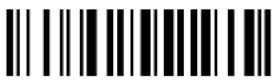 |
No Match Result
clear data - no transmission

transmit data using standard format

This selection determines the action to be taken when codes read do not conform to the advanced format requisites (no match).
- Codes not matching can be ignored, cleared from memory and not transmitted.
- Codes not matching can be transmitted using the Standard formatting (Headers, Code Length, Code ID, Terminators).
RADIO PARAMETERS
PowerScan ^® M8300 Series readers only
- RADIO PROTOCOL TIMEOUT
- RADIO RX TIMEOUT
POWER-OFF TIMEOUT
TRANSMISSION MODE
BEEPER CONTROL FOR RADIO RESPONSE
◦ SINGLE STORE ◎
◦ BATCH MODE ◦
FINDME
- Read the Enter Configuration code ONCE, available at the top of each page.
- Read configuration codes from the desired groups.
= Read the code and follow the procedure given - Read the Exit and Save Configuration code ONCE, available at the top of each page.
RADIO PROTOCOL TIMEOUT
radio protocol timeout
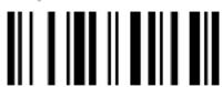
Read a number from the table where:
02-19 = timeout from 2 to 19 seconds
◆ 2 seconds
See section 5.9.1 for details.
RADIO RX TIMEOUT
radio RX timeout
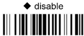
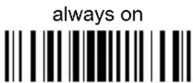
Read 2 numbers in the range 05-99:
05-99 = Radio RX timeout range from 05 to 99 seconds.

NOTE
This functionality is available only for stand-alone layout.
See section 5.9.2 for details.
POWER-OFF TIMEOUT
power-off timeout

Read 2 numbers in the range 00-99:
00 = Power-off disabled; reader always ready
01-99 = corresponds to a max. 99 hour delay before power-off.
◆ power-off after 4 hours.
See section 5.9.4 for details.
BEEPER CONTROL FOR RADIO RESPONSE
only good decode

only good reception

See section 5.9.5 for details.
SINGLE STORE
◆ disable

one attempt
two attempts
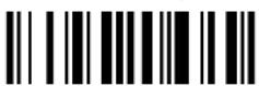
three attempts

four attempts

five attempts
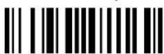
six attempts

seven attempts
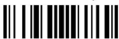
eight attempts

nine attempts
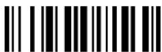
See section 5.9.6 for details
BATCH MODE
◆ disable batch

enable normal batch
enable automatic batch


See section 5.9.7 for details.
The following batch management parameters are complete commands and do not require reading the Enter and Exit configuration codes.
start normal batch transmission

+BFlush
delete batch data

+BReset
FIND ME
disable

◆ enable

See section 5.9.8 for details.
DISPLAY PARAMETERS
PowerScan ^® M8300 Series readers only
DATE AND TIME
CONTRAST
◎ FONT SIZE ◎
- BACKLIGHT
-
◎ DISPLAY OFF TIMEOUT ◎
◎ DISPLAY MODE ◎
KEYPAD
- Read the Enter Configuration code ONCE, available at the top of each page.
- Read configuration codes from the desired groups.
= Read the code and follow the procedure given - Read the Exit and Save Configuration code ONCE, available at the top of each page.
DATE AND TIME
set

date
Read 6 numbers for DDMMYY
set time
Read 4 numbers for HHMM
CONTRAST
lighter
darker
Read the code until the desired contrast is reached.
FONT SIZE
◆ small
medium

large
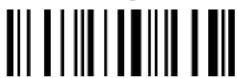
BACKLIGHT
◆ backlight off
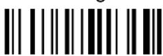
backlight on

DISPLAY-OFF TIMEOUT
timeout

Read 2 numbers in the range 00-99:
00 = disables display timeout (always on)
01 to 99 = timeout from 1 to 99 seconds.
◆ display-off after 8 seconds.
◆ delay disabled
DISPLAY MODE
normal
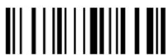
◆ local echo
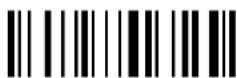
clear display after decode
See section 5.10.1 for details.
KEYPAD
disable reader keypad

◆ enable reader keypad and select characters
Read 3 HEX characters in the range 00-FE, corresponding to the left, center and right keys respectively.
$$ \mathbf {F F} = \text { KeyID disabled } $$
$$ \begin{array}{r l} \blacklozenge & \text { left } = ^ {\prime < } \ & \text { center } = ^ {\prime} = ^ {\prime} \ & \text { right } = ^ {\prime} > ^ {\prime} \end{array} $$
See section 6.2 for details.
5 REFERENCES
5.1 RS-232 PARAMETERS
5.1.1 Handshaking
Hardware handshaking: (RTS/CTS)
The RTS line is activated by the decoder before transmitting a character. Transmission is possible only if the CTS line (controlled by the Host) is active.
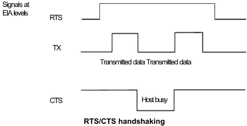
Software handshaking: (XON/XOFF)
During transmission, if the Host sends the XOFF character (13 Hex), the decoder interrupts the transmission with a maximum delay of one character and only resumes when the XON character (11 Hex) is received.
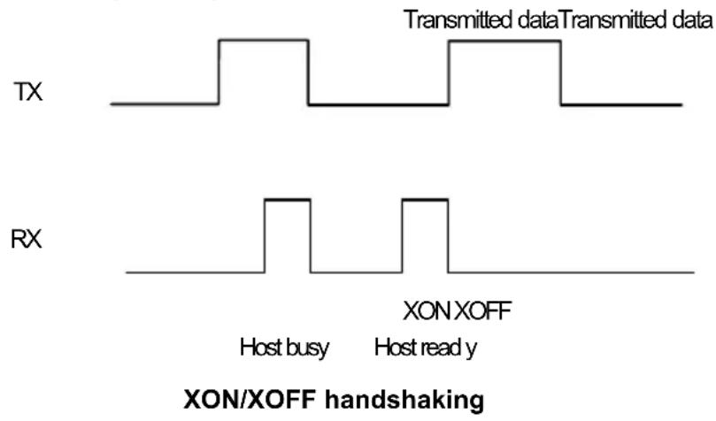
5.1.2 ACK/NACK Protocol
PowerScan® D8330 Readers
This parameter sets a transmission protocol in which the Host responds to the reader after every code transmitted. The Host sends an ACK character (06 HEX) in the case of good reception or the NACK character (15 HEX) requesting re-transmission, in the case of bad reception.

flowchart
graph LR
    A["PowerScan® D8330"] -->|data| B(( ))
    B -->|cable| A
    A -->|Host| C["ACK or NACK"]
    C --> A
ACK/NACK enabled
If the reader does not receive an ACK or NACK, transmission is ended after the RX Timeout (see section 5.1.4).
When ACK/NACK protocol is enabled, FIFO must be disabled manually, see section 5.1.3.
PowerScan® M8300 Readers
The transmission protocol takes place between reader, cradle and Host. The reader passes its data (code read) to the cradle, which sends it to the Host. The management of responses (from Host or cradle) depends on the Transmission Mode parameter, see section 5.9.4.
In the following descriptions the completed transmission is indicated by the Beeper Control for Radio Response parameter with its default setting to Normal, see section 5.9.5.
When ACK/NACK is disabled (in One-Way tx mode), there is no control from cradle to Host transmission, the reader responds with the good reception tone.
Transmission Mode = One-Way

flowchart
graph LR
    A["PowerScan® M8300"] -->|data| B["BC-80X0"]
    B -->|data| C["Host"]
    B -->|cable| C
    D["good RX beep"] --> B
    style A fill:#f9f,stroke:#333
    style B fill:#ccf,stroke:#333
    style C fill:#cff,stroke:#333
Transmission Mode = Two-Ways
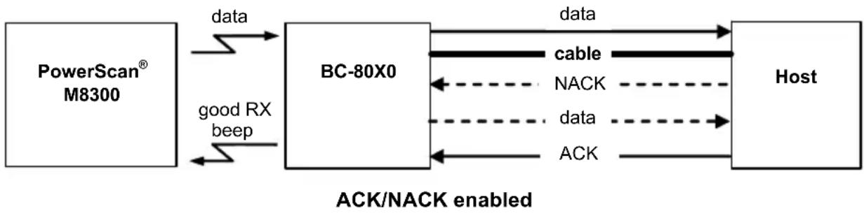
flowchart
graph LR
    A["PowerScan® M8300"] -->|data| B["BC-80X0"]
    B -->|data| C["Host"]
    B -->|good RX beep| A
    B -->|NACK| B
    B -->|data| C
    B -->|ACK| C
    style B fill:#f9f,stroke:#333
    style C fill:#ccf,stroke:#333
When ACK/NACK is enabled (in Two-Way tx mode), the Host sends an ACK character (06 HEX) in the case of good reception or the NACK character (15 HEX) requesting re-transmission, in the case of bad reception. Only after the ACK character is received by the BC-80X0 does the reader respond with the good reception tone.
If the BC-80X0 does not receive an ACK or NACK, transmission is ended after the RX Timeout, see section 5.1.4. See also Radio Protocol Timeout, section 5.9.1.
When ACK/NACK protocol is enabled, FIFO must be disabled manually, see section 5.1.3.
5.1.3 FIFO
PowerScan® D8330 Readers
This parameter determines whether data (bar codes) are buffered on a First In First Out basis allowing faster data collection in certain cases for example when using slow baud rates and/or hardware handshaking.
If the FIFO buffering is enabled, codes are collected and sent out on the serial line in the order of acquisition. About 800 characters can be collected (buffer full), after which the reader signals an error and discards any further codes until the transmission is restored.
If the FIFO buffering is disabled, each code must be transmitted before another one can be read.
PowerScan ^® M8300 Readers
If enabled, the BC-80X0 collects all messages sent by PowerScan ^® M8300 and sends them in order of acquisition to the connected Host.
If disabled, PowerScan ^® M8300 blocks message transmission until the BC-80X0 has completed transmission towards the Host.
5.1.4 RX Timeout
When the RS-232 interface is selected, the Host can be used to configure the device by sending it command strings (see Appendix A).
This parameter can be used to automatically end data reception from the Host after the specified period of time.
If no character is received from the Host, after the timeout expires, any incomplete string (any string not terminated by
5.2 PEN PARAMETERS
5.2.1 Minimum Output Pulse
This parameter sets the duration of the output pulse corresponding to the narrowest element in the bar code. In this way the code resolution is controlled by the signal sent to the decoder, independently of the physical resolution of the code read.
The shortest pulse (200 s) corresponds to a high-resolution code emulation and therefore a shorter transfer speed to the decoder (for decoders able to work on high resolution codes). Likewise, longer pulses correspond to low-resolution code emulation and therefore a longer transfer time to the decoder.
5.2.2 Conversion to Code 39 and Code 128
PowerScan® D8330 Series Readers
When using these readers it is possible to convert all codes to Code 39. By disabling this option the decoded codes will be transmitted in their original format, except for the following codes, which are ALWAYS converted into Code 39 format:
MSI, Code 11, Code 16K, Code 49, GS1 DataBar™.
PowerScan® M8300 Series Readers
When using these readers it is possible to choose between converting the decoded codes into either Code 39 format or Code 128 format. It is not possible to disable conversion.
5.2.3 Overflow
This parameter generates a white space before the first bar and after the last bar of the code. The selections are as follows:
narrow = space 10 times the minimum output pulse.
medium = space 20 times the minimum output pulse.
wide = space 30 times the minimum output pulse.
5.2.4 Output and Idle Levels
The following state diagrams describe the different output and idle level combinations for Pen emulation:
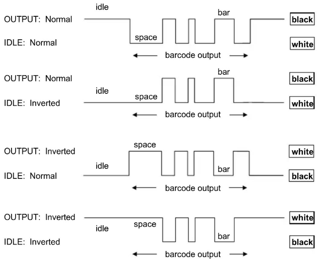
Output and Idle Levels
5.2.5 Inter-Block Delay
For the PEN Emulation interface, data are sent to the Host in fixed size blocks of 20 characters each. The inter-block delay parameter allows setting a delay between each block sent to the Host.
5.3 NETWORK PARAMETERS
5.3.1 Slave Address Range First/Last
These parameters define the valid addresses for the Slave cradles on the network. Valid values are in the range 0 to 1999. However, the maximum number of cradles in a single network is 16, (including the Master if present). All cradles in the system must have different addresses.
To reduce system boot time, it is recommended to number the Slaves consecutively, while it is not necessary that the Master cradle address is contained in the range. The network addresses correspond to the radio addresses, see section 4.7.
At system power-up, the Master searches for and initializes all the Slaves found in the valid address range. During this phase the yellow LED on the Master cradle blinks. The time to complete the start up procedure varies depending on the complexity of the network but is typically between a few seconds to a few minutes. Start up cannot be interrupted. At the end of this procedure the system will be operative and can collect data from all devices.

CAUTION
All Slaves must be powered up either before or together with the Master. Slaves successively powered will not be recognized by the system even if their address is in the specified range.
5.3.2 Network Warning Message
The Master cradle can transmit warning messages to the Host regarding some network errors.
/*Slave xxxx not responding*/: when the Master can no longer communicate with the specified Slave previously identified at start up.
/*Frame out of sequence for terminal xxxx*/: if a reader is sending data packets out of sequence. This can happen if there are transmission problems on the network (either connection or communication), or if the reader has correctly transmitted data to a device not on the network (reader configuration error).
The message is sent in the following format:
"Message" CR LF
5.3.3 Reception Warning Message
The Master cradle can transmit warning messages to the Host regarding wrong reception of data. Example:
/\*Two-Ways Out of Sequence!(.....)\*/
This message is transmitted to the Host by the Master cradle when the Master cradle receives a closing string from the Host for a Two-way tx communication, but this was either not open or already closed, therefore the data will be lost. See section 5.9.4.
5.3.4 Master Header/Terminator Selection
In addition to the standard header/terminator selection, the Master cradle can add its own header/terminator to the entire message sent to the Host.
In the STAR-System ^™ network headers and terminators for all RF Devices are disabled by default.
The Master header and terminator default values are as follows depending on the interface selection towards the Host:
RS-232: no header, terminator CR-LF
WEDGE: no header, terminator ENTER
See sections 5.4.1 and 5.4.2.
5.4 DATA FORMAT
For an overview of Message Formatting see Chapter 6.
5.4.1 Header/Terminator Selection
The header/terminator selection is not effected by the reading of the restore default code. In fact, header and terminator default values depend on the interface selection:
RS-232: no header, terminator CR-LF
WEDGE: no header, terminator ENTER
These default values are always restored through the reading of RS-232 or WEDGE interface selection code, see chapter 2.
For the WEDGE interface, the following extended keyboard values can also be configured:
| EXTENDED KEYBOARD TO HEX CONVERSION TABLE | ||||
| IBM AT IBM 3153APPLE ADB | IBM XT IBM | 31xx, 32xx, 34xx, 37xx | Wyse Digital | |
| HEX | KEY | KEY | KEY | KEY |
| 83 ENTER | ENTER | FIELD | EXIT | RETURN |
| 84 TAB | TAB | TAB | TAB | |
| 85 F1 | F1 | F1 | F1 | |
| 86 F2 | F2 | F2 | F2 | |
| 87 F3 | F3 | F3 | F3 | |
| 88 F4 | F4 | F4 | F4 | |
| 89 F5 | F5 | F5 | F5 | |
| 8A F6 | F6 | F6 | F6 | |
| 8B F7 | F7 | F7 | F7 | |
| 8C F8 | F8 | F8 | F8 | |
| 8D F9 | F9 | F9 | F9 | |
| 8E F10 | F10 | F10 | F10 | |
| 8F F11 | ESC | F11 | F11 | |
| 90 F12 | BACKSPACE | F12 | F12 | |
| 91 HOME | HOME | ENTER | F13 | |
| 92 | END | END | RESET | F14 |
| 93 | PG UP | PG UP | INSERT | F15 |
| 94 | PG DOWN | PG DOWN | DELETE | F16 |
| 95 | ↑ | ↑ | FIELD - | UP |
| 96 | ↓ | ↓ | FIELD + | DOWN |
| 97 | ← | ← | ENTER (Paddle) | LEFT |
| 98 | → | → | RIGHT | |
| 99 | ESC | ESC | ESC | |
| 9A | CTRL (Right) | CTRL (Right) | CTRL (Right) | |
| 9B | Euro | Space | Space | Space |
For all devices using IBM AT (compatible) Wedge or USB-KBD interfaces, all values from 9C to FE send the relative simulated keypress when available or else the relative ALT-Mode sequence. See the Hex to Character Conversion Table in Appendix C.
For all devices using other Wedge interfaces, all values from 9C to FE send the Space character.
5.4.2 Define Special Key Sequence
The Special Key(s) for Wedge IBM AT-PS/2 and USB-KBD interface users can be associated with a sequence of keyboard keys that otherwise could not be selected, i.e. ALT + F6, SHIFT + F1. These Special Keys can be used for:
- Headers/Terminators
- Character Replacement
- Field Adjustment
- Custom Code ID
- Advanced Formatting – Define Field
- Advanced Formatting – Additional Fixed Field
Follow the procedure to define the desired Special Key sequence:
- Read the Enter Configuration code above and select the Special Key to define (one at a time):
Define Special Key 1

Define Special Key 2

Define Special Key 3
Define Special Key 4
Define Special Key 5

- Read only one code to be associated with the special key sequence:

OR
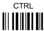
OR
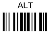
OR
CTRL + SHIFT

OR
ALT + SHIFT

OR
CTRL + ALT

- Select the character to be associated with the Special Key sequence by reading the codes corresponding to the 3 character values from Appendix C. Then, read the Exit and Save Configuration code above to complete the Special Key sequence.
The character values having the ^S and ^A symbols require SHIFT or ALT keys or key combinations in step 2, in particular:
^s = the character is obtained in combination with SHIFT
^A = the character is obtained in combination with ALT
The following character values change according to the keyboard nationality.
| KEYBCHAR | ITA | USA | FR | BE | DE | UK | ES | ||
| ! | 016^S | 016^S | 04A | 03E | 016^S | 016^S | 016^S | 016^S | 016^S |
| " | 01E^S | 052^S | 026 | 026 | 01E^S | 01E^S | 01E^S | 01E^S | 01E^S |
| # | 052^A | 026^S | 026^A | 026^A | 05D | 05D | 026^A | 026^S | 026^S |
| 025^S | 025^S | 05B | 05B | 025^S | 025^S | 025^S | 025^A | 025^S | |
| % | 02E^S | 02E^S | 052^S | 052^S | 02E^S | 02E^S | 02E^S | 02E^S | 02E^S |
| & | 036^S | 03D^S | 016 | 016 | 036^S | 03D^S | 036^S | 036^S | 036^S |
| ' | 04E | 052 | 025 | 025 | 05D^S | 052 | 04E | 05D | 03D^S |
| ( | 03E^S | 046^S | 02E | 02E | 03E^S | 046^S | 03E^S | 03E^S | 03E^S |
| ) | 046^S | 045^S | 04E | 04E | 046^S | 045^S | 046^S | 046^S | 046^S |
| * | 05B^S | 03E^S | 05D | 05B^S | 05B | 03E^S | 05B^S | 05D^S | 052^S |
| + | 05B | 055^S | 055^S | 04A^S | 05B | 055^S | 05B | 04E | 04C^S |
| , | 041 | 041 | 03A | 03A | 041 | 041 | 041 | 041 | 041 |
| - | 04A | 04E | 036 | 055 | 04A | 04E | 04A | 04A | 04E |
| . | 049 | 049 | 041^S | 041^S | 049 | 049 | 049 | 049 | 049 |
| / | 03D^S | 04A | 049^S | 049^S | 03D^S | 04A | 03D^S | 03D^S | 04A |
| 0 | 045 | 045 | 045^S | 045^S | 045 | 045 | 045 | 045 | 045 |
| 1 | 016 | 016 | 016^S | 016^S | 016 | 016 | 016 | 016 | 016 |
| 2 | 01E | 01E | 01E^S | 01E^S | 01E | 01E | 01E | 01E | 01E |
| 3 | 026 | 026 | 026^S | 026^S | 026 | 026 | 026 | 026 | 026 |
| 4 | 025 | 025 | 025^S | 025^S | 025 | 025 | 025 | 025 | 025 |
| 5 | 02E | 02E | 02E^S | 02E^S | 02E | 02E | 02E | 02E | 02E |
| 6 | 036 | 036 | 036^S | 036^S | 036 | 036 | 036 | 036 | 036 |
| 7 | 03D | 03D | 03D^S | 03D^S | 03D | 03D | 03D | 03D | 03D |
| 8 | 03E | 03E | 03E^S | 03E^S | 03E | 03E | 03E | 03E | 03E |
| 9 | 046 | 046 | 046^S | 046^S | 046 | 046 | 046 | 046 | 046 |
| : | 049^S | 04C^S | 049 | 049 | 049^S | 04C^S | 049^S | 049^S | 052 |
| ; | 041^S | 04C | 041 | 041 | 041^S | 04C | 041^S | 041^S | 04C |
| < | 061 | 041^S | 061 | 061 | 061 | 041^S | 061 | 061 | 041^S |
| = | 045^S | 055 | 055 | 04A | 045^S | 055 | 045^S | 045^S | 04E^S |
| > | 061^S | 049^S | 061^S | 061^S | 061^S | 049^S | 061^S | 061^S | 049^S |
| ? | 04E | 04A^S | 03A^S | 03A^S | 04E^S | 04A^S | 04E^S | 04E^S | 04A^S |
| @ | 04C^A | 01E^S | 045^A | 01E^A | 015^A | 052^S | 01E^A | 01E^A | 054 |
| [ | 054^A | 054 | 02E^A | 054^A | 052^S | 054 | 054^A | 03E^A | 05B |
| \ | 00E | 05D | 03E^A | 061^A | 04C^S | 061 | 00E^A | 04E^A | 051 |
| ] | 05B^A | 05B | 04E^A | 05B^A | 054^S | 05B | 05B^A | 046^A | 05D |
| ^ | 055^S | 036^S | 046^A | 054 | 00E | 036^S | 054^S | 05B^S | 055 |
| _ | 04A^S | 04E^S | 03E | 055 | 04A^S | 04E^S | 04A^S | 04A^S | 051^S |
| '(accent) | - | 00E | 03D^A | 05D^A | 055^S | 00E | 054 | 055^S | 054^S |
| a | 01C | 01C | 015 | 015 | 01C | 01C | 01C | 01C | |
| b | 032 | 032 | 032 | 032 | 032 | 032 | 032 | 032 | 032 |
| c | 021 | 021 | 021 | 021 | 021 | 021 | 021 | 021 | 021 |
| d | 023 | 023 | 023 | 023 | 023 | 023 | 023 | 023 | 023 |
| e | 024 | 024 | 024 | 024 | 024 | 024 | 024 | 024 | 024 |
| f | 02B | 02B | 02B | 02B | 02B | 02B | 02B | 02B | 02B |
| g | 034 | 034 | 034 | 034 | 034 | 034 | 034 | 034 | 034 |
| h | 033 | 033 | 033 | 033 | 033 | 033 | 033 | 033 | 033 |
| i | 043 | 043 | 043 | 043 | 043 | 043 | 043 | 043 | 043 |
| j | 03B | 03B | 03B | 03B | 03B | 03B | 03B | 03B | 03B |
| k | 042 | 042 | 042 | 042 | 042 | 042 | 042 | 042 | 042 |
| l | 04B | 04B | 04B | 04B | 04B | 04B | 04B | 04B | 04B |
| m | 03A | 03A | 04C | 04C | 03A | 03A | 03A | 03A | 03A |
| n | 031 | 031 | 031 | 031 | 031 | 031 | 031 | 031 | 031 |
| o | 044 | 044 | 044 | 044 | 044 | 044 | 044 | 044 | 044 |
| p | 04D | 04D | 04D | 04D | 04D | 04D | 04D | 04D | 04D |
| q | 015 | 015 | 01C | 01C | 015 | 015 | 015 | 015 | 015 |
| r | 02D | 02D | 02D | 02D | 02D | 02D | 02D | 02D | 02D |
| s | 01B | 01B | 01B | 01B | 01B | 01B | 01B | 01B | 01B |
| t | 02C | 02C | 02C | 02C | 02C | 02C | 02C | 02C | 02C |
| u | 03C | 03C | 03C | 03C | 03C | 03C | 03C | 03C | 03C |
| v | 02A | 02A | 02A | 02A | 02A | 02A | 02A | 02A | 02A |
| CHAR | ITA | USA | FR | BE | DE | UK | ES | ||
| w | 01D | 01D | 01A | 01A | 01D | 01D | 01D | 01D | 01D |
| x | 022 | 022 | 022 | 022 | 022 | 022 | 022 | 022 | 022 |
| y | 035 | 035 | 035 | 035 | 01A | 035 | 035 | 035 | 035 |
| z | 01A | 01A | 01D | 01D | 035 | 01A | 01A | 01A | 01A |
| - | 054^S | 025^A | 046^A | 052 | 054^S | 052^A | 03D^A | 05B^S | |
| | | 00E^S | 05D^S | 036^A | 016^A | 04C | 061^S | 016^A | 061^A | 06A^S |
| - | 05B^S | 055^A | 045^A | 054 | 05B^S | 05D^A | 045^A | 05D^S | |
| ~ | - | 00E^S | 01E^A | 04A^A | 04E | 05D^S | - | 05B^A | 055^S$ |

NOTE
To use upper case letters, it is necessary to read one of the SHIFT commands from step 2 before the value corresponding to the lower case letters.
The following key values are common to all the keyboard nationalities.
| KEYB KEY | ITA | USA | FR | BE | DE | UK | ES | SW | JP |
| ENTER | 05A | 05A | 05A | 05A | 05A | 05A | 05A | 05A | 05A |
| TAB | 00D | 00D | 00D | 00D | 00D | 00D | 00D | 00D | 00D |
| F1 | 005 | 005 | 005 | 005 | 005 | 005 | 005 | 005 | 005 |
| F2 | 006 | 006 | 006 | 006 | 006 | 006 | 006 | 006 | 006 |
| F3 | 004 | 004 | 004 | 004 | 004 | 004 | 004 | 004 | 004 |
| F4 | 00C | 00C | 00C | 00C | 00C | 00C | 00C | 00C | 00C |
| F5 | 003 | 003 | 003 | 003 | 003 | 003 | 003 | 003 | 003 |
| F6 | 00B | 00B | 00B | 00B | 00B | 00B | 00B | 00B | 00B |
| F7 | 083 | 083 | 083 | 083 | 083 | 083 | 083 | 083 | 083 |
| F8 | 00A | 00A | 00A | 00A | 00A | 00A | 00A | 00A | 00A |
| F9 | 001 | 001 | 001 | 001 | 001 | 001 | 001 | 001 | 001 |
| F10 | 009 | 009 | 009 | 009 | 009 | 009 | 009 | 009 | 009 |
| F11 | 078 | 078 | 078 | 078 | 078 | 078 | 078 | 078 | 078 |
| F12 | 007 | 007 | 007 | 007 | 007 | 007 | 007 | 007 | 007 |
| Home | 26C | 26C | 26C | 26C | 26C | 26C | 26C | 26C | 26C |
| End | 269 | 269 | 269 | 269 | 269 | 269 | 269 | 269 | 269 |
| PG UP | 27D | 27D | 27D | 27D | 27D | 27D | 27D | 27D | 27D |
| PG down | 27A | 27A | 27A | 27A | 27A | 27A | 27A | 27A | 27A |
| CHAR\KEYB | ITA | USA | FR | BE | DE | UK | ES | SW | JP |
| Up arrow | 275 | 275 | 275 | 275 | 275 | 275 | 275 | 275 | 275 |
| Downarrow | 272 | 272 | 272 | 272 | 272 | 272 | 272 | 272 | 272 |
| Leftarrow | 26B | 26B | 26B | 26B | 26B | 26B | 26B | 26B | 26B |
| Rightarrow | 274 | 274 | 274 | 274 | 274 | 274 | 274 | 274 | 274 |
| Esc | 076 | 076 | 076 | 076 | 076 | 076 | 076 | 076 | 076 |
| Ctrlright | 214 | 214 | 214 | 214 | 214 | 214 | 214 | 214 | 214 |
| € | 02E^A | 02E^A | 024^A | 024^A | 024^A | 025^A | 02E^A | 02E^A | - |
| SPACE | 029 | 029 | 029 | 029 | 029 | 029 |

NOTE
If Caps Lock Auto-Recognition is disabled, it is necessary to verify that the keyboard caps lock status matches the reader one.
EXAMPLES
- Defining Special Key Sequences -
- the following example allows defining Special Key 1 as SHIFT + F5:
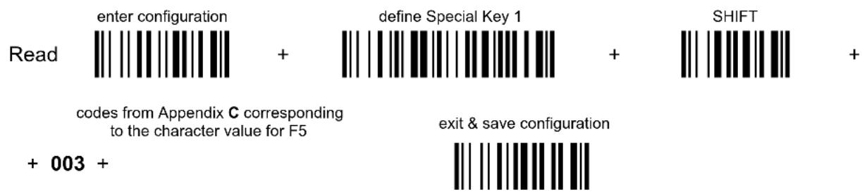
- the following example allows defining Special Key 2 as CTRL + S (upper case):
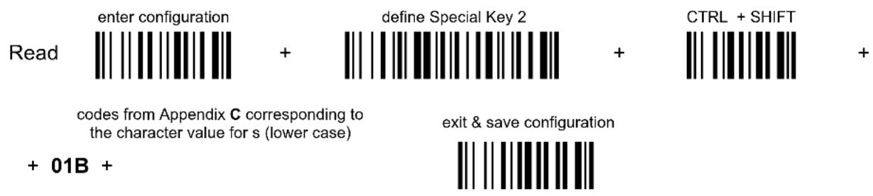
- the following example allows defining Special Key 3 as Alt + F6:
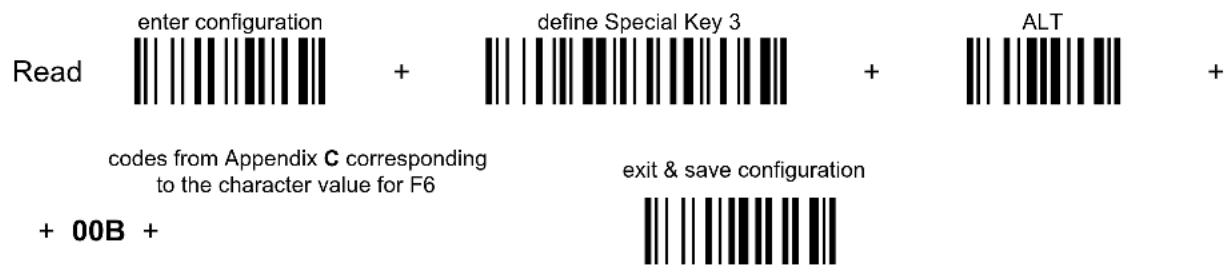
- the following example allows defining Special Key 4 as Alt + Shift + F1:
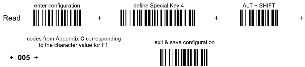
- Integrating Special Keys in Headers/Terminators -
- the following example allows setting Special Key 1 (defined in example 1 above) as terminator:

- the following example allows setting Special Key 2 (defined in example 2 above) as header:

- the following example allows setting Special Key 3 (defined in example 3 above) as header:

- the following example allows setting Special Key 4 (defined in example 4 above) and ENTER character as terminators:
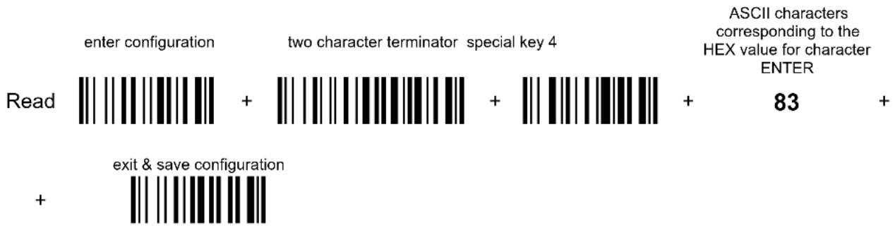
bar
| Category | Value | | ---------------------------- | ----- | | Enter configuration | + | | Two character terminator special key 4 | + | | ASCII characters corresponding to the HEX value for character ENTER | 83 | | Exit & save configuration | |5.4.3 Address Stamping
It is possible to include the reader address in the message sent to the host. The Reader Address Stamping and the Cradle Address Stamping parameters consist of a 4-digit number in the range 0000 to 1999.
For message output format, refer to chapter 6.
5.4.4 Address Delimiter
The Address Delimiter allows a character to be included to separate the reader Address stamping field from the next field in the message. Any character can be included in the hexadecimal range from 00 to FE.
For message output format, refer to chapter 6.
5.4.5 Time Stamping Format
The Time Stamping parameter sets the format for hour and date information. It consists of 1 or 2 groups of numbers, each one made up of 6 decimal digits.
For example, setting the Hour/Minutes/Seconds/Month/Day/Year format, the information 17:03:16 on June 12, 2002 will be formatted as 170316061202.
5.4.6 Time Stamping Delimiter
The Time Stamping Delimiter allows a character to be included to separate the Time Stamping field from the next field in the message. Any character can be included in the hexadecimal range from 00 to FE.
5.5 POWER SAVE
5.5.1 Sleep State
When using interfaces other than USB, this mode allows the P in the reader to enter a “Sleep” state for minimum power consumption. For D-series readers, this command is only valid when hardware trigger type is selected.
Before entering Sleep mode, the following are verified:
- no commands coming from Host
- no data being transmitted to Host
- Enter Sleep Timeout ended (see section 5.5.2)
To exit Sleep mode press the trigger.
For M8300 series readers, sleep state is entered immediately after reading a code and is not configurable. To exit Sleep mode press the trigger.
When using the USB interface, this mode allows the device to manage Selective Suspend conditions generated by the Host Operating System in which optimizing low power consumption (ex. Windows Stand-by). It is possible to exit the Suspend mode either from the Host (ex. moving the mouse during Stand-by) or through the bar code reader. The latter, called Remote Wakeup, makes the device wake up the Host restoring the communication. Remote Wakeup is possible by pressing the trigger.
5.5.2 Enter Sleep Timeout
For readers that have the Sleep state enabled, this timeout determines when the reader will enter this state.
5.6 READING PARAMETERS
5.6.1 Trigger Signal
This mode determines how the reading phase is controlled when the hardware trigger operating mode is selected:
- trigger active level: the reader goes ON when the trigger is pressed and goes OFF when it is released
- trigger active pulse: the reader goes ON at the first trigger press and goes OFF only at a second press
5.6.2 Trigger Click
When enabled, it activates a "click" sound upon each trigger pressure.
5.6.3 Trigger-Off Timeout
When this timeout is selected, the reader turns OFF automatically after the desired period of time.
5.6.4 Reads per Cycle
In general, a reading cycle corresponds to the ON + OFF times of a device.
The resulting effects of this parameter on code reading depend on other related configuration conditions. Here are the definitions of ON and OFF times.
- For readers using the software trigger parameter (FLASH MODE), a reading cycle corresponds to the flash on + flash off times. Code reading takes place during the flash on time.
- For readers using the hardware trigger parameter, a reading cycle corresponds to a trigger press (ON) + one of the following OFF events:
trigger release (for trigger active level)
a second trigger press (for trigger active pulse)
trigger-off timeout (see section 5.6.3).
When one read per cycle is selected, the device decodes only one code during the ON period and immediately turns the reader OFF. It is only possible to read another code when the next ON time occurs.
In multiple reads per cycle, the ON period is extended so that the device can continue decoding codes until an OFF event occurs. For software trigger mode, the flash on period is immediately reset after each read and therefore extended. If another code is decoded before the reset flash on period expires, it is again reset and the effect is that the device remains ON, decoding codes until the flash on or timeout period expires.
The Safety Time parameter should be used in this case to avoid unwanted multiple reading of the same code, see section 5.6.5.
5.6.5 Safety Time
Safety time prevents the device from immediately decoding the same code more than once. Same code consecutive reading can be disabled requiring the reader to be removed from the code (no decoding) for at least 400 ms, or a timeout can be set up to 9.9 seconds before the decoder will accept the same code. Reading is immediate if the code changes.
The safety time parameter is not applicable when reading stacked codes or when setting one read per cycle in hardware trigger operating mode, since these settings require voluntary action by the user.
5.7 DECODING PARAMETERS

CAUTION
These parameters are intended to enhance the decoding capability of the reader for particular applications. Used incorrectly, they can degrade the reading performance or increase the possibility of a decoding error.
5.7.1 Ink-Spread
The ink-spread parameter allows the decoding of codes, which are not perfectly printed because the page texture tends to absorb the ink.
5.7.2 Overflow Control
The overflow control parameter can be disabled when decoding codes printed on small surfaces, which do not allow the use of an overflow space.
This command does not affect code families 2/5, Code 128 and Code 93.
5.7.3 Interdigit Control
The interdigit control parameter verifies the interdigit spacing for code families Code 39 and Codabar.
5.8 ADVANCED FORMATTING
5.8.1 Match Conditions
Selecting an Advanced Formatting and specifying a Match restriction (Code Type, Code Length, Predefined Characters) the code will be transmitted according to the order of the defined formats.
For example, defining 2 formats where:
- Format 1: Match Code type = Code128
- Format 2: Match Code length = 15 and Match with Predefined Characters "DATA"
a Code128 "DATA:12345ABCDE" with code length 15 will be formatted following the Format 1.
To send the same code with the Format 2 it is necessary to invert the format order as follows:
- Format 1: Match Code length = 15 and Match with Predefined Characters "DATA"
- Format 2: Match Code type = Code128
5.9 RADIO PARAMETERS (M8300 SERIES ONLY)
5.9.1 Radio Protocol Timeout
This parameter sets the valid time to wait before transmission between the M8300 series reader and BC-80X0 cradle is considered failed.
This parameter should be set taking into consideration the radio traffic (number of readers in the same area).
If the RS-232 interface is used with ACK/NACK enabled, this parameter should be at least equal to the RX Timeout parameter for low traffic environments. It should be increased if there are many readers in the same area.
It can be set between 2 and 19 seconds.
5.9.2 Radio RX Timeout
When the scanner is used in a standalone layout (point-to-point or with multiple readers) it can be configured to receive “asynchronous” messages from the host at any time.
There are two modes which can enable the scanner to receive messages from the host:
1) Enable “2 way” Communication Protocol – After the transmission of each bar code, the scanner waits for an acknowledgement from the host ^1 . A message can be sent by the host accompanying this acknowledgement, or in place of it, to display something on the screen or execute a command (such as sound a beep sequence, turn an LED on or off, etc.). If no acknowledgement or message is received from the host within a programmable timeout duration, the radio will be switched off and an “error transmission” beep will be sounded.
2) Independent of the Selected Protocol – The scanner can be configured to keep the radio receiver “awake” for a defined period of time following each transmission. Any message coming from the host1 before expiration of the timeout is accepted. The parameter “Radio RX Timeout” is used for specifying how long the scanner have to wait for a message after receiving each code transmission.
In this mode, the radio can also be “awakened” by pressing the trigger. The scanner can receive a message only if it is linked to the Base (i.e. the scanner has been joined to the Base and has had at last one “valid” transmission after the last power-on). Setting the “Radio RX timeout” value to “00” specifies that the radio never goes into sleep mode (always awake → the scanner can receive a message at any time). Choosing this setting will, of course, consume battery life more quickly.
^1 See Section 6.1 for Host to Scanner message formatting.
5.9.3 Power-Off Timeout
If this command is enabled, after the desired timeout in hours, the PowerScan ^® batteries are disconnected and all power consumption ceases. To restore power, press the trigger once. The reader will now be ready to read codes.
Power-off does not affect configuration parameters.
5.9.4 Transmission Mode
This parameter determines whether the reader receives responses or messages from the Host or not. In One-Way tx mode, neither Host nor cradle responds to the reader.
In Two-Way tx mode, the reader must receive a response from either the cradle or the Host.
The cradle responds (empty message) to the reader, only after good transmission to the Host, for the following conditions: ACK/NACK enabled, see section 5.1.2; WEDGE or PEN interface. For these conditions, it is suggested to prolong the Radio Protocol Timeout, see section 5.9.1.
Enabling Two-Way tx mode temporarily disables FIFO buffering see section 5.1.3.
With ACK/NACK disabled, the Host responds to the reader (through the cradle) with an answer message (message to reader display or command to reader), see section 6.1 and the following figure.
Transmission Mode = Two-Ways

flowchart
graph LR
    A["PowerScan® M8300"] -->|message| B["BC-80X0"]
    B -->|data| C["Host"]
    B -->|cable| C
    C -->|Host answer message Host answer| B
    B -->|data| C
5.9.5 Beeper Control for Radio Response
For M8300 series readers, the data entry good read tone normally results in two beeps; the first indicates that the reader has decoded the code; the second indicates whether BC-80X0 has received the data.
This can be changed according to the following selections:
♦ Normal: both good decode and good receptions are signaled (two beeps).
♦ Only Good Decode: only the first beep indicating a good read is signaled.
- Only Good Reception: only the second beep indicating a good reception is signaled.
- Off: Neither good read nor good reception beeps are signaled.
For all configurations, any transmission errors will always be signaled.
5.9.6 Single Store
When single store mode is enabled, if the PowerScan ^® M8300 fails to transmit a code to the cradle, it enters a special operating mode that prevents the user from reading bar codes. When such operating mode is entered, the trigger no longer enables bar code reading but is used to retry transmission itself for the number of attempts selected in configuration. Once the transmission is successful the reader returns to the standard mode. If transmission is not successful after the number of configured attempts, the code is discarded.
Single store may be useful if you often read codes at the limit of the coverage area and there is a chance that code transmission can fail. In such case single store allows you to move to a more favorable position or location (i.e. closer to the cradle) and retry transmission without the necessity of re-reading the code since it is already stored in the reader.
Conversely, if single store is disabled, and the user wants to retry transmission, the code must be read again, and therefore the attempt must be made from basically the same location. If the user gives up, he does not know if the transaction was successful. (Actually the transmission could have been successful but the cradle may have been unable to acknowledge the message). There are applications in which there is no risk of transmission failure. In such cases it may be better to disable single store so that the user perceives a more consistent behavior of the trigger in that it always corresponds to code reading.
5.9.7 Batch Mode
This Operating Mode allows storing read codes in the internal reader RAM memory. The stored codes are transmitted to the base station at a later time according to the type of batch mode selected.
Batch mode can be enabled either manually (normal batch mode) or automatically.
Normal batch mode temporarily suspends radio communication between reader and base station allowing codes to be stored in the reader on a FIFO basis. This can be useful for example, if codes must be read from a location where there is no radio network. Upon returning to the system working area, this mode requires reading the Start Normal Batch Transmission bar code to successively transmit the list of stored codes to the base station. The FIFO management assures that the first code read will be the first code to be transmitted to the base station.
The Delete Batch Data bar code allows canceling all bar code data stored in the reader.
Automatic batch mode allows codes to be stored in the reader on a FIFO basis whenever the reader is out of radio range. In this case radio communication is not suspended and transmission is attempted after each code read. If transmission
cannot be successfully completed, then the code is added to the list. When the reader returns in range, transmission of the codes to the base station resumes automatically, according to the selected communication protocol, upon simply pressing and releasing the trigger or by successfully reading a new code.
Each code is listed on the reader display together with its identifying position number and its total number of characters. The three keys under the display have the following function in batch mode:
| Key Function | ||
| ▲ | (left) Key | Scroll up in list |
| ENTER | (center) Key Delete highlighted code | |
| ▼ | (right) Key Scroll down in list | |
In batch mode, the selected Transmission Mode determines the behavior of the reader at the time the list of codes is transmitted. If One-way mode is enabled, the codes are transmitted one after the other without interruption. In Two-way mode, after transmitting each code, the reader waits for the Host answer message to be shown on the display. Therefore, in Two-way transmission mode and normal batch mode, the Start Normal Batch Transmission bar code must be read after each code to continue, whereas with automatic batch mode just pull and release the trigger after each code.
The code, which has a transmission pending, is shown on the display in reverse video indicating that it cannot be deleted.
5.9.8 Find Me (PowerScan ^® M8300 only)
If enabled, after a timeout of a few minutes in which PowerScan ^® M8300 is not used, it enters stand-by mode and its green LED starts blinking in order to signal its location.
5.10 DISPLAY PARAMETERS (SOME M8300 MODELS ONLY)
5.10.1 Display Mode
The user can control the reader display behavior according to the following selections:
Normal mode: When a bar code is read with the reader:
- The code is sent to the Host.
- The reader display is not cleared. Therefore if any previous data was displayed on the reader screen it remains.
- There is no Local Echo to the reader display.
Clear Display After Decode mode: When a bar code is read with the reader:
- The code is sent to the Host.
- The reader display is cleared. Therefore if any previous data was displayed on the reader screen it is cancelled and the screen remains blank.
- There is no Local Echo of the code to the reader display.
Local Echo mode: When a bar code is read with the reader:
- The code is sent to the Host.
- The reader display is cleared.
- The code is also sent to the reader display (Local Echo).
- The cursor is positioned after the last printed character on the reader display.
Host messages sent to the reader are always written to the reader display.
5.11 CONFIGURATION EDITING COMMANDS
The following commands carry out their specific function and then exit the configuration environment.
| Command | Description |
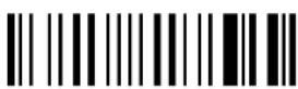 | Restore PowerScan® reader default configuration (see the relative Quick Reference Guide for default settings) |
 | Transmit the PowerScan® D8330 or PowerScan® M8300 software release |
 | Transmit PowerScan® reader configuration in ASCII format.This command is not effective with Pen emulation interface. |
 | Restore BC-80X0 default configuration (see the relative Quick Reference Guide for default settings) |
 | Transmit the BC-80X0 Software release. |
 | Transmit BC-80X0 configuration in ASCII format.This command is not effective with Pen emulation interface. |
5.12 CUSTOM DEFAULT CONFIGURATION
Read the following code to set the reader user-defined configuration as custom default configuration:
Save User-defined Configuration as Custom Default

Read the following code whenever you need to restore the custom default configuration:
Restore Custom Default Configuration

5.13 CODE TYPE RECOGNITION
This procedure allows the reader to enter a particular state during which it reads and transmits to the Host information about the family type of codes unknown to the user (with the exception of MSI, Code 49 and Code 16k code types). It is also possible to read and transmit configuration strings without interpreting them.
All codes are read ignoring the check digit.
Follow the given procedure:
① Read the following code to enter the code type recognition mode:
code type recognition

② Read existing codes whose family type you need to check.
③ Read the following code to return to the reader's normal functioning:
exit code type recognition mode

5.14 CONFIGURATION COPYING COMMANDS
5.14.1 Copy PowerScan ^® D8330 Series
Procedure:
① Connect the master (correctly configured reader) and the slave (reader to be configured) together through two RS-232 serial interface cables and external power supply. Accessory cables and power supply are available from your Psion Teklogix distributor to provide this connection.
RS-232 Cables: CAB471 & CAB472
Power Supply: PG5
② Using the slave reader, read the Restore Default bar code and then the RS-232 interface bar code from chapter 4 of this manual or from the Quick Reference Guide.
③ With the master reader, read the Configuration Copy bar code below.
Copy Configuration

The configuration will be copied from the master to the slave reader. The slave reader signals the end of the procedure with a series of beeps.
Note: The master reader can be configured for any interface.
5.14.2 Copy PowerScan ^® M8300 Series
Procedure:
① Using the slave reader and its BC-80X0 cradle, follow the initialization procedure in chapter 4 of this manual or from the Quick Reference Guide.
② With the master PowerScan ^® M8300 (correctly configured reader), read the Copy Configuration bar code below. Then place it onto an BC-80X0 cradle within 10 seconds. The reader will beep indicating the configuration has been copied.
The configuration will be simultaneously sent over the RS-232 interface of the BC-80X0. If this causes undesired effects disconnect the RS-232 cable between the PC and BC-80X0 during this process.
Copy Configuration

③ With the slave PowerScan ^® M8300, read the Get Configuration bar code below. Then place it onto the same BC-80X0 cradle used in the step above. The slave reader's address will not be changed.
Get Configuration

The configuration will be copied from the master to the slave PowerScan ^® M8300. The slave PowerScan ^® M8300 signals the end of the procedure with a series of beeps. It is now ready to be used with its own BC-80X0 cradle.
④ Repeat the procedure above to configure other slave readers. The BC-80X0 can continue to configure slave readers until it receives another command or data.
5.14.3 Copy BC-80X0
Procedure:
① Using the slave reader and its BC-80X0 cradle, read the Restore Default bar code, set the radio address, and then read the RS-232 interface bar code from chapter 4 of this manual or from the Quick Reference Guide.
② Connect the master BC-80X0 and the slave BC-80X0 (cradle to be configured) together through two RS-232 serial interface cables and external power supply. Accessory cables and power supply are available from your Psion Teklogix distributor to provide this connection.
RS-232 Cables: CAB471 & CAB472
Power Supply: PG12
③ Read the Configuration Copy bar code below with a reader. Then place it onto the master BC-80X0 cradle.
Copy Configuration

The configuration will be copied from the master BC-80X0 to the slave BC-80X0. The reader signals the end of the procedure with a series of beeps.
④ Repeat the procedure above to configure other slave cradles.
Note: The master BC-80X0 can be configured for any interface.
5.15 DEFAULT PARAMETERS FOR POS TERMINALS
The default values of the RS-232 and Data Format parameters for POS terminals are listed in the following table:
| NIXDORF | Mode | A | FUJITSU | |
| RS-232 Group | ||||
| Baud Rate 9600 9600 9600 | ||||
| Parity | Odd | None | ||
| Data Bits 8 8 8 | ||||
| Stop Bits | 1 1 1 | |||
| Handshaking | Hardware (RTS/CTS) | None | RTS always ON | |
| ACK/NACK Protocol | Disabled | Disabled | Disabled | |
| FIFO | Disabled | Enabled | Enabled | |
| Inter-Character Delay Disabled | Disabled | Disabled | ||
| RX Timeout | 9.9 sec | 2 sec | 9.9 sec | |
| Serial Trigger Lock | Disabled | Disabled | Disabled | |
| Data Format Group | ||||
| Code Identifier | Custom | Custom | Custom | |
| Header | No Header | No Header | No Header | |
| Terminator | CR | CR | CR | |
| Field Adjustment | Disabled | Disabled | Disabled | |
| Code Length TX | Not Transmitted | Not Transmitted | Not Transmitted | |
| Character Replacement | Disabled | Disabled | Disabled | |
| Address Stamping | Disabled | Disabled | Disabled | |
| Address Delimiter | Disabled | Disabled | Disabled | |
| Time Stamping | Disabled | Disabled | Disabled | |
| Time Delimiter Disabled | Disabled | Disabled | ||
The table below lists all the Code Identifiers available for the POS terminals:
| CODE | NIXDORF Mode A | FUJITSU | ICL Mode |
| UPC-A | A0 | A | A |
| UPC-E | C0 | E | E |
| EAN-8 | B | FF | FF |
| EAN-13 | A | F | F |
| Code 39 | M | None | C [code length] |
| Codabar | N | None | N [code length] |
| Code 128 | K | None | L [code length] |
| Interleaved 2 of 5 | I | None | I [code length] |
| Code 93 | L | None | None |
| Industrial 2 of 5 | H | None | H [code length] |
| UCC/EAN 128 P | None | L [code length] | |
| MSI | O | None | None |
| GS1 DATABARTM E | None | None | |
| Other | None | None | None |
5.16 FIRMWARE UPGRADE
Device firmware upgrades can be performed using the Downloader utility tool (downloadable from the original manufacturer's web site: http://www.scanning.datalogic.com) from your PC through the USB communication.
Procedure:
① Launch the Downloader tool on your PC.
② Connect the device to the PC via USB interface.
③ Read the code given below and position the reader onto the cradle:
prepare device for firmware upgrade
OR
Press the cradle button if present (to only update the cradle).
The device will automatically be reset.
④ Proceed with the firmware upgrade (see the Downloader utility help on-line for details).

CAUTION
Do not interrupt firmware upgrade downloading for any reason.
6 MESSAGE FORMATTING
The system always provides scanner to host data communication using the following message formatting:
Output Message from PowerScan® D8330 or PowerScan® M8300 Stand-alone Towards Host
[Header] [Scanner_Addr] [Scanner_Addr_delimiter] ] [Cradle_Addr] [Cradle_Addr_delimiter] [Time stamp] [Ts_delimiter] [Code ID] [Code Length] CODE [Terminator]
[Items in square brackets are optional.]
Output Message from PowerScan® M8300 STAR-System™ Towards Host [Time stamp] [Ts_delimiter] [Header] [Code ID] [Code Length] CODE [Terminator]
[Items in square brackets are optional.]
For PowerScan ^® M8300 models with display, if the RS-232 interface is selected for communication between the Host and the BC-80X0 cradle, then the following additional communications between Host and Scanner can occur:
- The Host can send messages to any scanner associated with that cradle to control the Scanner's display, LEDs and beeper.
- The Scanner can send up to 3 user-defined characters to the Host using the 3 command keys on the Scanner.
These communications and their relative message formatting are detailed in the following paragraphs.
6.1 MESSAGES FROM HOST TO READER
The general format to enable the Scanner for a 2 way communication is:
[Scanner_Addr] [Scanner_Addr_delimiter] MESSAGE [CR]
NOTE:
- If you have enabled the Scanner Address Stamping or the Scanner Address Delimiter, you must specify them in every message.
The general format for other asynchronous messages is:
[Scanner\_Addr] [Scanner\_Addr\_delimiter] [DC2] MESSAGE [CR]
where DC2 is ASCII 0x12 (^R) character.
- If you have not enabled the Scanner Address Stamping or the Scanner Address Delimiter, you must not specify them. In this case all messages will be implicitly addressed to the 'binded' Scanner of the cradle directly connected to the serial line.
- The Scanner can only receive messages if two-way mode is enabled. (See section 5.9.4, "Transmission Mode", command is on page 160).
- Messages cannot start with '\$+' because they would be interpreted as a configuration command.
- You can send a message to the Scanner only while it is on. This happens when it has sent a message to the host and the radio timeout has not yet expired. (See section 5.9.1, "Radio Protocol Timeout"; command is on page 131).
- If you want to control the Scanner's beeper from the host, you will also probably want to disable the good transmission beep that is emitted when the code is received from the cradle. (See command on page 87).
The message field can store plain text and escape sequences.
- Escape sequences are interpreted as commands.
- Plain text is directly printed on the display. If writing beyond the end of line, the display does not wrap automatically. Extra characters are ignored. Control characters are not interpreted (i.e. LF, FF, etc.).
6.1.1 Cursor Control
ESC [nA Up n rows, no scroll
ESC [nB Down n rows, no scroll
ESC [nC Right n columns
ESC [nD Left n columns
ESC [G CR
ESC [r; cH Move to row r, column c
(ESC[1;1H is the upper left character position of the display)
ESC D Down 1 row, with scroll
ESC E CR and cursor down 1 row with scroll
ESC M Up 1 row and scroll
NOTES:
- Since CR is used as the message terminator, you must use ESC [ G or ESC E to print a CR.
- The cursor row position is not affected by the currently selected font. The display always has 4 rows, so when writing with the large font, actually two rows are written to: the current one and the one below it. You will need two ESC E commands to step from one row to the next when using the large font.
- The cursor column position is affected by the currently selected font. Therefore, column 6 is 36 pixels from the left border only if you last selected the 6x8 font; otherwise it could be 48 or 72 pixels from the left border.
6.1.2 Font Selection
| ESC [0 m | Normal mode |
| ESC [7 m | Reverse mode |
| ESC # 4 | Large font: subsequent characters are written on the current row and the row below it using the 12x16 font which allows for two rows of eight characters on the display. |
| ESC # 5 | Normal font: subsequent characters are written using the 6x8 font, which allows for four rows of sixteen characters on the display. |
| ESC # 7 | Medium font: subsequent characters are written using the 8x8 font, which allows for four rows of twelve characters on the display. |
6.1.3 Clearing Display
| ESC [0 K | From cursor position to end of line inclusive |
| ESC [1 K | From beginning of line to cursor position (not inclusive) |
| ESC [2 K | Entire line |
| ESC [0 J | From cursor position to end of display inclusive |
| ESC [1 J | From beginning of display to cursor position (not inclusive) |
| ESC [2 J | Entire display; moves cursor to upper left corner on display |
6.1.4 LED and Beeper Control
| ESC [0 q | Emit short High tone + short delay |
| ESC [1 q | Emit short Low tone + short delay |
| ESC [2 q | Emit long Low tone + short delay |
| ESC [3 q | Emit good read tone |
| ESC [4 q | Emit bad tx tone |
| ESC [5 q | Wait 100 ms |
| ESC [6 q | Turn on the green LED |
| ESC [7 q | Turn off the green LED |
| ESC [8 q | Turn on the red LED |
| ESC [9 q | Turn off the red LED |
The LED control escape sequences are intended to activate the LEDs for short periods of time and can be used in combination with the Beeper. The LED and Beeper will be controlled by the system after the entire command sequence is interpreted.
Example:
ESC [6 q ESC [3 q ESC [7 q
Turns on the green LED, emits a good read tone, and turns off the green LED.
ESC [6 q ESC [5 q ESC [7 q
Turns on the green LED for 100 ms and then turns off the green LED.
6.1.5 Setting RTC
ESC [0 p d d m m y y
Set date to day, month, year
ESC [1 p h h m m
Set time to hours, minutes; seconds are automatically set to 00.
6.2 MESSAGES FROM SCANNER COMMAND KEYS
The PowerScan ^® M8300 series scanners with display have 3 command keys that can each be associated with a character to send to the host.
By pressing the keys on the scanner, the associated character with its relative message formatting is sent to the Host. For example, keys can be used to select items from a menu sent to the scanner display by the application program.
The general format is:
[Header] [Scanner_Addr] [Scanner_Addr_delimiter] ] [Cradle_Addr] [Cradle_Addr_delimiter] [Time stamp] [Ts_delimiter] [Code ID] [Code Length] KeyID [Terminator]
[Items in square brackets are optional.]
The messages are handled by the system as if they were bar codes, that's why KeyID can have so many fields appended to it. If in your application there is some chance of reading a 1-char bar code identical to KeyID, the way you can distinguish between the two is to enable the Code ID: The KeyID is the only 1-character long EAN 8 code.
Refer to section 5.3 for a compete description of the optional message fields in square brackets.
The default characters associated with each key (KeyID) are shown in the following table:
| Default Key Identifiers | |||
| Key KeyID | |||
| ▲ (left) Key '<' | |||
| ENTER | (center) Key '=' | ||
| ▼ | (right) | Key | '>' |
7 TECHNICAL FEATURES
7.1 POWERSCAN ^® D8330
| Electrical Features | PowerScan® D8330 PowerScan® D8330 AR | |
| Power Supply 4 to 30 VDC | ||
| Max. Consumption | ||
| @ 4V | 420 mA | 500 mA |
| @ 5V | 310 mA | 370 mA |
| @ 30 V | 62 mA | 70 mA |
| Sleep Mode | 4 mA | 4 mA |
| Reading Indicators | Good Read LED (green)Good Read Spot (green), Beeper | |
| Host Interfaces | ||
| RS-232 300 to 38400 baud | ||
| WEDGE | IBM AT or PS/2, XT, PC Notebook, IBM SURE1, IBM 3153, 31xx, 32xx, 34xx, 37xx terminals, Wyse terminals, Digital VT terminals, Apple ADB Bus supported | |
| PEN Emulation | Selectable minimum pulse from 200 μS to 1.2 mS | |
| USB | USB-KBD, USB-KBD-ALT-MODE, USB-KBD APPLE, USB-COM, USB-IBM-Table Top, USB-IBM-Hand Held | |
| Laser Features | D8330 | D8330 |
| Light Source VLD between 630~680 nm | ||
| Scan Rate 35 ± 5 scans/sec | ||
| Power (max) in mW 0.9 mW 1.3 mW | ||
| Scan Angle 42° | 13.5° ± 0.7 | |
| PCS minimum(Manufacturer's Test Chart) | 15% | 25% |
| Maximum Resolution 0.076 mm (3 mils) | 0.19 mm (7.5 mils) | |
| Reading Field Width | see reading diagrams (section 7.6) | |
| Laser Safety Class | Class 2 EN 60825-1/CDRH | |
| Environmental Features | ||
| Working Temperature | -30° to +50 °C / -22° to +122 °F | |
| Storage Temperature | -30° to +70 °C / -22° to +158 °F | |
| Humidity | 90% non condensing | |
| Drop resistance (on concrete) | IEC 68-2-32 Test ED 2 m | |
| Protection class | IP65 | |
| Mechanical Features | ||
| Weight (without cable) | about 295 g (10.4 oz) | |
| Dimensions | 205 x 114 x 69 mm (8.07 x 4.49 x 2.72 in) | |
| Cable length | 2 m (6 ft 6 in) | |
| Material | Polycarbonate molded with rubber | |
7.2 POWERSCAN ^® M8300
| Electrical and General Features | ||
| Battery Type 2150 Li-Ion battery pack | ||
| Recharge Time | max. 4 hours with external power supply max 10 hours with Host power | |
| Operating autonomy (continuous reading) | 60,000 reads (typical) | |
| Display (Only available with some models) | LCD 4 lines x 16 chars Programmable font and backlight | |
| Indicators Good Read LED (green) | Good Read Spot (green), Beeper | |
| Laser Features | M8300 | M8300 |
| Light Source VLD between 630~680 nm | ||
| Scan Rate 35 ± 5 scans/sec | ||
| Power (max) in mW 0.9 mW 1.3 mW | ||
| Scan Angle 42° | 13.5° ± 0.7 | |
| PCS minimum (Manufacturer's Test Chart) | 15% | 25% |
| Maximum Resolution 0.076 mm (3 mils) | 0.19 mm (7.5 mils) | |
| Reading Field Width see reading diagrams (section 7.6) | ||
| Laser Safety Class CLASS 2 EN 608 | 25-1 / CDRH | |
| Environmental Features | ||
| Working Temperature | -20° to +50 °C / -4° to +122 °F | |
| Storage Temperature | -20° to +70 °C / -4° to +158 °F | |
| Humidity | 90% non condensing | |
| Drop resistance (on concrete) IEC 68-2-32 Test ED | 2 m | |
| Protection Class | IP65 (IP64 for models with display) | |
| Mechanical Features | ||
| Weight (with batteries) | about 400 g (14.10 oz) | |
| Dimensions | 212 x 109 x 71 mm (8.34 x 4.49 x 2.79 in) | |
| Material | Polycarbonate molded with rubber | |
7.3 BC-80X0 / C-8000
| BC-80X0 | C-8000 | ||
| Electrical and General Features | |||
| Supply Voltage | |||
| External Power 10 to 30 VDC | |||
| Host Power 5 VDC ±10% | |||
| Power Consumption | |||
| External Power max. 10 W (charging)* | |||
| Host Power max. 500 mA (charging) | |||
| Indicators Ext. Power /Data yellow LED Host Power/Data yellow LED Reader batt. state green/red LED Aux. batt. state green/red LED (BC-8000/C-8000 only) beeper | |||
| Recharge Time | |||
| External Power max. 4 hours with 2150 mAh Li-Ion battery | |||
| Host Power max. 10 hours with 2150 mAh Li-Ion battery | |||
| Host Interfaces | |||
| RS-232 300 to 38400 baud 9600 baud | |||
| WEDGE | IBM AT or PS/2, XT, PC Notebook, IBM SURE1, IBM 3153, 31xx, 32xx, 34xx, 37xx terminals, Wyse terminals, Digital VT terminals, Apple ADB Bus supported | Not supported | |
| PEN Emulation | Selectable minimum pulse from 200 μS to 1.2 mS | Not supported | |
| USB | USB-KBD, USB-KBD-ALT-MODE, USB-KBD APPLE, USB-COM, USB-IBM-Table Top, USB-IBM-Hand Held | USB-COM | |
| Environmental Features | |||
| Working Temperature -20° to +50 °C / -4° to +122 °F** | |||
| Storage Temperature | -20° to +70 C / -4° to +158° F | ||
| Humidity | 90% non condensing | ||
| Protection | IP40 | ||
| Mechanical Features | |||
| Weight without cable | about 380 g / 13.4 oz | ||
| Dimensions (without antenna) | 204 x 108 x 95 mm / 9.44 x 4.25 x 3.74 in | ||
| Material | ABS | ||
* Having a switching regulator inside, the BC-80X0 and C-8000 draw the same power, regardless of the supply voltage. i.e. as the input voltage increases the current drawn decreases.
** Batteries must be charged at a temperature ranging from 0° to +40 °C / +32° to +104 °F.
7.4 SYSTEM AND RADIO FEATURES
| Radio Features | European Models USA Models | |
| Radio Frequency 433.92 MHz 910 MHz | ||
| Bit Rate 19200 36800 | ||
| Range (in open air) 50 m 30 m | ||
| System Configurations | BC-8000 model only ST | ARGATE ^TM |
| Maximum number of devices per base station | 32 | 255 |
| Maximum number of devices in the same reading area | 2000 | |
| Maximum number of base stations in network | 16 (including cradle Master) | |
7.5 STATUS INDICATORS
The scanner has two indicator LEDs and a Beeper. The BC-8000 and C-8000 cradles have four LED indicators (three for BC-8010 model) and a Beeper. They signal several operating conditions, which are described in the tables below.
$$ \mathbf {H} = \text { high tone } \quad \mathbf {L} = \text { low tone } $$
POWERSCAN® D8330/M8300 READER START-UP
| Beeper1 | Meaning |
| LLLL Parameters loaded correctly | |
| HHH long tones | Parameter loading error, reading or writing error in the non volatile memory |
| HLHL Hardware error in EEPROM | |
POWERSCAN® D8330/M8300 READER CONFIGURATION
| Beeper1 | Meaning |
| H H H H Correct entry or exit from Configuration mode | |
| L Good read of a command | |
| L L L | Command read error |
POWERSCAN® D8330/M8300 READER DATA ENTRY
| Beeper ^1 | LED | Good Read | Spot Meaning |
| one beep ^2 | ON ON | Correct read of | a code in normal mode |
| H L long | TX buffer full (when FIFO is enabled) or TX error between PowerScan ^ M8300 and BC-8000 | ||
| H long ON | ON Successful advanced format concatenation | ||
| H H H | Timeout expired – operation not completed | ||
| H H long | Error in advanced data formatting | ||
| OFF | OFF Ready to read a code | ||
^1 Only the Beeper Intensity command can modify these signals.
^2 The data entry good read tone is user-configurable with all the Beeper commands in the Reading Parameters section.
For M-series readers, normally this results in two beeps; the first indicates that the reader has decoded the code, the second indicates whether BC-80X0 has received the data. See also section 5.9.5.
POWERSCAN ^® M8300 POWER
| Beeper | LED | Meaning |
| 10 short H | 10 short blinks | Low Battery |
| H M L | Power off |
H = high tone
M = medium tone
L = low tone
POWERSCAN ^® M8300 BIND, JOIN, COPY COMMANDS
| Beeper ^1 | LED | Meaning |
| Blinking | Command accepted; reader ready to be inserted into the cradle | |
| L | Success | |
| H L long tones | Failure |
BC-80X0/C-8000 POWER/COMMUNICATION
| Aux LED Host LED | Meaning | |
| Yellow | Yellow | |
| OFF | OFF | Device off |
| ON Power applied through an external power supply | ||
| ON Power applied through the Host | ||
| Flashing Flashing Transmission over the Host port | ||
BC-80X0/C-8000 CHARGE STATUS
| Reader LED | Meaning | ||
| Red | Green | Beeper | |
| OFF OFF No reader battery inserted | |||
| ON Reader battery in charge | |||
| ON single beep Reader battery completely charged | |||
| Flashing orange | Reader battery fault | ||
| Alternating red/green | repetitive beep | Charging out of temperature range, over-current or over-voltage conditions | |
| Alternating red/green every 30 seconds | beep every 30 seconds | Reader not correctly inserted onto cradle, no charging takes place | |
| Spare LED (not for BC-8010) | Meaning | ||
| Red | Green | Beeper | |
| OFF OFF No Spare battery inserted in the SBS-3000 slot | |||
| ON Spare battery in charge | |||
| ON | Spare battery completely charged | ||
| Flashing orange | Spare battery fault | ||
| Alternating red/green | repetitive beep | Charging out of temperature range, over-current or over-voltage conditions | |
| Alternating red/green every 30 seconds | beep every 30 seconds | Spare battery not correctly inserted into SBS-3000, no charging takes place | |
7.6 READING DIAGRAMS
POWERSCAN® D8330/M8300
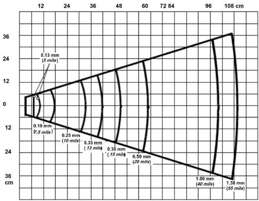
line
| Depth (mm) | Value | | ---------- | --------- | | 0.13 | 5 | | 0.19 | 7.5 | | 0.25 | 10 | | 0.33 | 13 | | 0.38 | 15 | | 0.50 | 20 | | 1.00 | 40 | | 1.38 | 55 |POWERSCAN® D8330/M8300 AR models
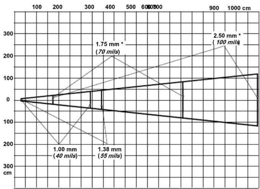
line
| Depth (mm) | Value | | ---------- | --------- | | 1.00 | 40 mils | | 1.38 | 55 mils | | 1.75 | 70 mils | | 2.50 | 100 mils |*on reflective labels.
NOTE: Typical performance at 20^ C / 68^ F on high quality bar codes
A HOST CONFIGURATION STRINGS
In this section we provide a description of how to modify the device configuration using serial strings sent from the Host.
This method requires the RS-232 interface.
The device configuration can be changed by receiving commands from the Host through the serial interface. When this method is used, the programming sequence format is the following:
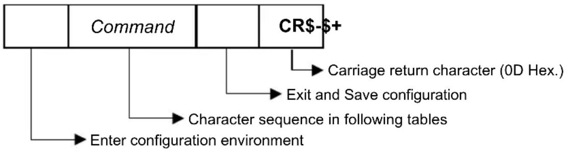
flowchart
graph TD
    A["Command"] --> B["CR-+"]
    B --> C["Carriage return character (0D Hex.)"]
    B --> D["Exit and Save configuration"]
    B --> E["Character sequence in following tables"]
    E --> F["Enter configuration environment"]
Example:
Multiple command programming sequence:
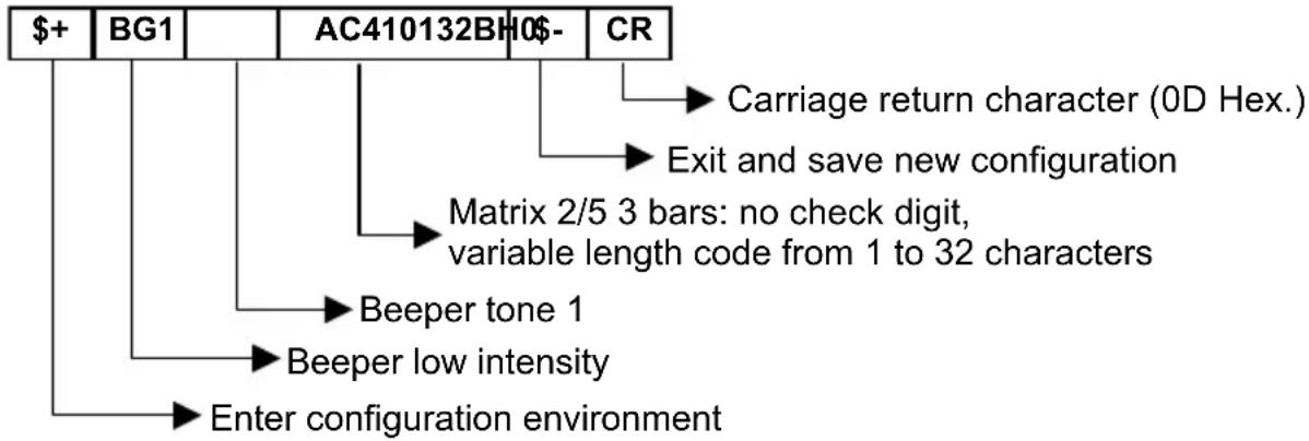
flowchart
graph TD
    A["$+"] --> B["BG1"]
    B --> C["AC410132BH"]
    C --> D["CR"]
    D --> E["Carriage return character (0D Hex.)"]
    D --> F["Exit and save new configuration"]
    C --> G["Matrix 2/5 3 bars: no check digit, variable length code from 1 to 32 characters"]
    C --> H["Beeper tone 1"]
    C --> I["Beeper low intensity"]
    C --> J["Enter configuration environment"]
Each configuration parameter setting removes the condition previously active for that parameter.

NOTE
The device buffer can contain about 400 characters. If your programming string goes over this value, you must split it into separate groups and send each group after a delay of at least 3 seconds to give the reader time to empty the buffer and interpret the commands.
SERIAL CONFIGURATION STRINGS
| SPECIAL CONFIGURATION COMMANDS | |
| DESCRIPTION | STRING |
| Enter Configuration + | |
| Exit and Save Configuration- | |
| Restore Default +* | |
| Transmit Software Release (not for PEN emulation) +! | |
| Transmit Device Configuration in ASCII (not for PEN emulation) +& | |
| Set Custom Default +0 | |
| Restore Custom Default +1 | |
These commands do not require \$-.
| INTERFACE SELECTION | |||
| DESCRIPTION | STRING | ||
| RS-232 Standard CP0 | |||
| WEDGE | for IBM AT | CP500 | |
| for IBM Terminals: 31xx, 32xx, 34xx, 37xx; make-break keyboard | CP501 | ||
| for IBM Terminals: 31xx, 32xx, 34xx, 37xx; make-only keyboard | CP502 | ||
| Keyboard Type for IBM Terminals 31xx, 32xx, 34xx, 37xx | typewriter | FK0 | |
| advanced | FK1 | ||
| for IBM XT | |||
| for IBM Terminal 3153 | CP504 | ||
| for IBM PC Notebook | CP505 | ||
| for IBM SURE1 | |||
| for IBM AT - ALT mode | CP507 | ||
| for IBM PC Notebook - ALT mode | CP508 | ||
| for Wyse Terminal - ANSI Keyboard | CP509 | ||
| for Wyse Terminal - PC Keyboard | CP510 | ||
| for Wyse Terminal - ASCII Keyboard | CP511 | ||
| for Wyse Terminal - VT220 style Keyboard | CP514 | ||
| for Digital Terminals VT2xx/3xx/4xx | CP512 | ||
| PEN EMULATION | CP6 | ||
| USB | USB-KBD | UA03 | |
| USB-KBD-ALT-MODE | UA04 | ||
| USB-KBD-APPLE | UA05 | ||
| USB-COM | UA02 | ||
| USB-IBM-Table Top | UA00 | ||
| USB-IBM-Hand Held | UA01 | ||
| RS-232 | |||
| DESCRIPTION | STRING | ||
| Baud Rate 300 CD1 | |||
| 600 | CD2 | ||
| 1200 | CD3 | ||
| 2400 | CD4 | ||
| 4800 | CD5 | ||
| 9600 | CD6 | ||
| 19200 | CD7 | ||
| 38400 | CD8 | ||
| Parity | none CC0 | ||
| even | CC1 | ||
| odd | CC2 | ||
| Data Bits 7 CA0 | |||
| 8 CA1 | |||
| 9 CA2 | |||
| Stop Bits 1 CB0 | |||
| 2 CB1 | |||
| Handshaking | disable CE0 | ||
| RTS/CTS | CE1 | ||
| XON/XOFF | CE2 | ||
| RTS always On | CE3 | ||
| ACK/NACK Protocol | disable | ER0 | |
| enable | ER1 | ||
| FIFO | disable | EC0 | |
| enable | EC1 | ||
| Inter-character Delay (ms) | CK00 - CK99 | ||
| RX Timeout (100 ms) | CL00 - CL99 | ||
| Serial Trigger Lock | disable | CR0 | |
| enable and select characters | CR1ab | ||
a= Hex values representing an ASCII character from 00 to FE enabling the device trigger.
b = HEX values representing an ASCII character from 00 to FE inhibiting the device trigger.
| USB | ||
| DESCRIPTION | STRING | |
| USB-COM | ||
| Handshaking | disable | CE0 |
| RTS/CTS | ||
| XON/XOFF | ||
| RTS always | ||
| ACK/NACK Protocol disable ER0 | ||
| FIFO | enable | |
| Inter-character Delay (ms) CK00 - CK99 | ||
| RX Timeout (100 ms) | CL00 - CL99 | |
| Serial Trigger Lock disable CR0 | ||
| ab | ||
| USB-KBD | ||
| Keyboard Nationality(not for USB-KBD-ALT-MODE) | Belgian FJ7 | |
| English (UK) | FJ4 | |
| French | ||
| German | FJ3 | |
| Italian | FJ1 | |
| Spanish | FJ6 | |
| Swedish | ||
| USA | FJ0 | |
| Keyboard Nationality(IBM AT compatible only) | Japanese | FJ8 |
| Russian (Latin) | FJ9 | |
| Russian (Cyrillic) | ||
| Hungarian | FJB | |
| Slovenian, Croatian, Serbian (Latin) | FJC | |
| Romanian | FJD | |
| Czech Republic | ||
| FIFO | disable | EC0 |
| enable | ||
| Delays | Inter-Character (ms) | CK00 - CK99 |
| Inter-Code (s) | FG00 - FG99 | |
| USB Keyboard Speed | normal | UT10 |
| fast | UT01 | |
a= Hex values representing an ASCII character from 00 to FE enabling the device trigger.
b = HEX values representing an ASCII character from 00 to FE inhibiting the device trigger.
| WEDGE | ||
| DESCRIPTION | STRING | |
| Keyboard Nationality Belgian FJ7 | ||
| English | (UK) | |
| French | ||
| German | FJ3 | |
| Italian | ||
| Spanish | FJ6 | |
| Swedish | FJ5 | |
| USA | ||
| Keyboard Nationality Japanese FJ8 (IBM AT compatible only) | ||
| Russian (Latin) FJ9 | ||
| Russian | (Cyrillic) | |
| Hungarian | FJB | |
| FJC | ||
| Romanian | FJD | |
| Czech | Republic | |
| Caps Lock | caps Lock ON | FE1 |
| caps | Lock | |
| Caps Lock Auto-Recognition (IBM AT compatible only) | disable | FP0 |
| enable | FP1 | |
| Num Lock num lock unchanged | toggle num lock | FL1 |
| FL0 | ||
| Delays | Inter-Character (ms) | CK00 - CK99 |
| Inter-Code (s) | FG00 - FG99 | |
| Control Character Emulation Ctrl + Key | Ctrl + Shift + Key | FO0 |
| FO1 | ||
| PEN | ||
| DESCRIPTION | STRING | |
| Operating Mode | interpret (does not require + or-) | ] |
| transparent (does not require+ or -) | [ | |
| Minimum Output Pulse | 200μs | DG0 |
| 400μs | DG1 | |
| 600μs | DG2 | |
| 800μs | DG3 | |
| 1 ms | DG4 | |
| 1.2 ms | DG5 | |
| Conversion to Code 39 and Code 128 | disable conversion to Code 39(D series only) | DA0 |
| enable conversion to Code 39 | DA1 | |
| enable conversion to Code 128(M series only) | DA2 | |
| Output Level | normal | DD0 |
| inverted | DD1 | |
| PEN (continued) | ||
| DESCRIPTION | STRING | |
| Idle Level normal DE0 | ||
| inverted | ||
| Overflow | narrow overflow | |
| medium | overflow | |
| wide overflow | ||
| Inter-block Delay (100 ms) | CK00-CK99 | |
| NETWORK | ||
| DESCRIPTION | STRING | |
| RS-485 Network Disable Net | work RZ0 | |
| Enable RS-485 | ||
| Enable RS-485 | ||
| Slave Address Range | Minimum Address | JB0000-1999 |
| Maximum Address | ||
| Network Baud Rate | 9600 | JE0 |
| 19200 | JE1 | |
| 38400 | JE2 | |
| Network Warning Message | not transmitted | JG0 |
| transmitted | JG1 | |
| Transmission Warning Message | not transmitted | JH0 |
| transmitted | JH1 | |
| Master Header | no header | JA00 |
| one character | x | |
| two characters | xx | |
| three characters | xxx | |
| four characters | xxxx | |
| five characters | xxxxx | |
| six characters | xxxxxx | |
| seven characters | xxxxxxxx | |
| eight characters | xxxxxxxxx | |
| Master Terminator | no terminator | JA10 |
| one character | x | |
| two characters | xx | |
| three characters | xxx | |
| four characters | xxxx | |
| Five characters | JA15xxxxx | |
| six characters | JA16xxxxxx | |
| seven characters | JA17xxxxxxxx | |
| eight characters | xxxxxxxxx | |
x= Hex value from 00 to FE representing an ASCII character
| DATA FORMAT | ||
| NOT FOR PEN EMULATION INTERFACES | ||
| DESCRIPTION | STRING | |
| Code Identifier disable EBO | ||
| Manufacturer | Standard | |
| AIM | standard | |
| custom | ||
| Custom Code Identifier EH | abc | |
| Headers | no header | |
| one character | x | |
| two characters | xx | |
| three characters | xxx | |
| four characters | xxxx | |
| five characters | EA05 xxxxx | |
| six characters | EA06 xxxxxx | |
| seven characters | xxxxxxxx | |
| eight characters | EA08xxxxxxxx | |
| Terminators | no terminator | EA10 |
| one character | x | |
| two characters | xx | |
| three characters | xxx | |
| four characters | xxxx | |
| five characters | EA15 xxxxx | |
| six characters | EA16 xxxxxx | |
| seven characters | xxxxxxxx | |
| eight characters | EA18xxxxxxxx | |
EB3
E/A
a = ASCII character.
b, c, x = HEX values representing an ASCII character.
a = ASCII character of the MANUFACTURER STANDARD Code Identifier from the table on page 71.
b = Hex value of the first Custom Code Identifier character from 00 to FD; FF = disable Code Identifier
c= Hex value of the second Custom Code Identifier character from 00 to FD; FF = disable second character of Custom Code Identifier
x= Hex value from 00 to FE
| DATA FORMAT (continued) | ||
| NOT FOR PEN EMULATION INTERFACES | ||
| DESCRIPTION | STRING | |
| Code Length Tx not transmitted transmitted in variable-digit transmitted in fixed 4-digit format | EE0 | |
| format EE1 | ||
| format EE2 | ||
| Field Adjustment disable EF0 | ||
| a0 d | ||
| a1 d | ||
| a2 d | ||
| a3 d | ||
| Field Adjustment Character EG | e | |
| Character Replacement disable character replacement EO0 | ||
| afg | ||
| EO2afg | ||
| afg | ||
| Address Stamping | disable reader address stamping | RU0 |
| enable reader address stamping | RU1 | |
| disable cradle address stamping | RW0 | |
| enable cradle address stamping RW1 | ||
| Address Delimiter | disable reader address delimiter | RV0 |
| enable reader address delimiter and select character | RV1 h | |
| disable cradle address delimiter | RY0 | |
| enable cradle address delimiter and select character | RY1 h | |
| Time Stamping | disable IL0 | |
| hour/minutes/seconds/month/day/year | IL1 | |
| hour/minutes/seconds/day/month/year | IL2 | |
| hour/minutes/seconds | IL3 | |
| month/day/year | IL4 | |
| day/month/year | IL5 | |
| Time Stamping Delimiter | disable time stamping delimiter | IM0 |
| enable time stamping delimiter and select character | IM1h | |
a= ASCII character.
d= a number from the Hex/Numeric Table
e, f, g, h= HEX values representing an ASCII character
a= ASCII character of the MANUFACTURER STANDARD Code Identifier from the table on page 71.
d = a number in the range 01-32 from the Hex/Numeric Table
e= Hex value from 00 to FE
f= Hex value of the character to be replaced from 00 to FE
g= Hex value of the new character to insert from 00 to FE
FF = replace with no new character (remove character)
h = a HEX value in the range from 00 - FE representing the ASCII character.
| POWER SAVE | ||
| DESCRIPTION | STRING | |
| Sleep State disable BQ0(only for D8330 series) | ||
| enable BQ1 | ||
| Enter Sleep Timeout (100 ms) | BR00-BR99 | |
| READING PARAMETERS | ||
| DESCRIPTION | STRING | |
| Trigger Type software trigger BK0 | ||
| hardware trigger | ||
| always on | ||
| Trigger Signal trigger active level | BA0 | |
| trigger | active | |
| Trigger Click disable Bc0 | ||
| enable | Bc1 | |
| Trigger-off Timeout (s) | BD00 - BD99 | |
| FLASH ON (100 ms) | BB001 - BB099 | |
| FLASH OFF (100 ms) | BB101 - BB199 | |
| Reads per Cycle | one read | BC0 |
| multiple | reads | |
| Safety Time (100 ms) | BE00 - BE99 | |
| Beeper Intensity | very low intensity | BG0 |
| low intensity | ||
| medium intensity | ||
| high intensity | ||
| Beeper Tone | tone 1 | BH0 |
| tone 2 | ||
| tone 3 | ||
| tone 4 | ||
| Beeper Type | monotone | BJ0 |
| bitonal | BJ1 | |
| Beeper Length | long | BI0 |
| short | BI1 | |
| Good Read Spot Duration | disable | BV0 |
| short | BV1 | |
| medium | BV2 | |
| long | BV3 | |
| Aiming System | disabled | Bj0 |
| enabled | Bj1 | |
| Cradle Beeper Intensity | disable | JI0 |
| low intensity | ||
| medium intensity | ||
| high intensity | ||
| DECODING PARAMETERS | ||
| DESCRIPTION | STRING | |
| Ink-spread | disable AX0 | |
| enable | AX1 | |
| Overflow Control disable | AW1 | |
| enable | AW0 | |
| Interdigit Control disable | AV0 | |
| enable | AV1 | |
| Puzzle SolverTM | disable AU0 | |
| enable | AU1 | |
| Decoding Safety one read | ED0 | |
| two reads | ||
| three reads | ||
| four reads | ||
| CODE SELECTION | |||
| DESCRIPTION | STRING | ||
| DISABLE ALL FAMILY CODES | AZ0 | ||
| EAN/UPC | disable EAN/UPC family | AA0 | |
| EAN 8/EAN 13/UPC A/UPC E | without ADD ON | AA1 | |
| with ADD ON | AA5 | ||
| with and without ADD ON | AA8 | ||
| EAN 8/EAN 13 | without ADD ON | AA3 | |
| with ADD ON 2 ONLY | AAK | ||
| with ADD ON 5 ONLY | AAL | ||
| with ADD ON 2 AND 5 | AA6 | ||
| UPC A/UPC E | without ADD ON | AA4 | |
| with ADD ON 2 ONLY | AAM | ||
| with ADD ON 5 ONLY | AAN | ||
| with ADD ON 2 AND 5 | AA7 | ||
| EAN/UPC with and without Add On no Autodiscrimination | AA8Ad0 | ||
| EAN/UPC Autodiscrimination Add On by Prefix | AA8Ad1 | ||
| Select Prefixes | cancel all selections | ET0 | |
| 378/379 | ET1378ET2379 | ||
| 434/439 | ET3434ET4439 | ||
| 414/419 | ET5414ET6419 | ||
| 977 | ET7977 | ||
| 978 | ET8978 | ||
| 979 | ET9979 | ||
| EAN 8 check digit transmission | disable | AAG0 | |
| enable | AAG1 | ||
| EAN 13 check digit transmission | disable | AAH0 | |
| enable | AAH1 | ||
CODE SELECTION (continued)
| DESCRIPTION | STRING | ||
| UPC A check digit transmission disable AA10 enable | |||
| AA1 | |||
| UPC E check digit transmission disable AAJ0 enable | |||
| AAJ1 | |||
| conversions UPC E to UPC A AAA | |||
| UPC E to EAN 13 AAB | |||
| UPC A to EAN 13 AAC | |||
| EAN 8 to EAN 13 AAD | |||
| ISBN Conversion codes | enable ISBN AP1 | ||
| enable ISSN AP2 | |||
| enable ISBN and ISSN AP3 | |||
| disable ISBN and ISSN | AP0 | ||
| Code 39 disable Code 39 family | AB0 | ||
| Standard | no check digit control | AB11 | |
| check digit control and transmission | AB12 | ||
| check digit control without transmission | AB13 | ||
| Full ASCII | no check digit control | AB21 | |
| check digit control and transmission | AB22 | ||
| check digit control without transmission | AB23 | ||
| CIP 39 | AB3 | ||
| Code 32 | AB4 | ||
| code length | AB*xxxx | ||
| 2/5 disable Code 2/5 family | AC0 | ||
| Interleaved 2/5 no check d | git control AC11 | xxxx | |
| check digit control and transmission | AC12xxxx | ||
| check digit control without transmission | AC13xxxx | ||
| Normal 2/5 5 bars no check d | git control AC21 | xxxx | |
| check digit control and transmission | AC22xxxx | ||
| check digit control without transmission | AC23xxxx | ||
| Industrial 2/5 (IATA) no check d | git control AC31 | xxxx | |
| check digit control and transmission | AC32xxxx | ||
| check digit control without transmission | AC33xxxx | ||
| Matrix 2/5 3 bars no check d | git control AC41 | xxxx | |
| check digit control and transmission | AC42xxxx | ||
| check digit control without transmission | AC43xxxx | ||
| CIP/HR | AC5 | ||
xxxx = ASCII numbers that define the code length where:
- First 2 digits = minimum acceptable code length.
• Second 2 digits = maximum acceptable code length.
The minimum code length must always be less than or equal to the maximum.
The maximum code length for all codes is 99 characters:
Examples:
0132 = variable length from 1 to 32 digits in the code.
1010 = 10 digit code length only.
| CODE SELECTION (continued) | |||
| DESCRIPTION | STRING | ||
| Codabar Standard no start/stop character equality control | disable Codabar family AD0 | ||
| no start/stop character equality control | or transmission | AD111 | |
| character equality control | but transmission | AD112 | |
| character equality control | but no transmission | AD121 | |
| character equality control | and transmission | AD122 | |
| ABC Codabar no start/stop character equality control | char no start/stop character equality control | but transmission | AD212 |
| Codabar AB C forced concatenation AD232 | |||
| start/stop char code length | AD*xxxx | ||
| operator case in transmission lower case ADA0 | |||
| upper | case | ||
| Code 128 disable Code 128 family | AI0 | ||
| enable Code 128 - control without transmission of check digit | AI11 | ||
| enable EAN 128 - control without transmission of check digit | AI21 | ||
| Transmit GS before Code | disable | EQ0 | |
| enable | EQ1 | ||
| ISBT 128 | enable ISBT 128 | AI31 | |
| code length | AILxxxx | ||
| Code 93 disable Code 93 family | AK0 | ||
| enable Code 93 - control without transmission of check digit | AK1 | ||
| MSI disable the family | AE0 | ||
| no check | AE1 | ||
| MOD10 no tx | AE2 | ||
| MOD10 with tx | AE3 | ||
| MOD11-MOD10 no tx | AE4 | ||
| MOD11-MOD10 with tx AE5 | |||
| MOD10-MOD10 no tx | AE6 | ||
| MOD10-MOD10 with tx AE7 | |||
ADA1
xxxx = ASCII numbers that define the code length where:
- First 2 digits = minimum acceptable code length.
• Second 2 digits = maximum acceptable code length.
The minimum code length must always be less than or equal to the maximum.
The maximum code length for all codes is 99 characters:
EXAMPLES:
0132 = variable length from 1 to 32 digits in the code.
1010 = 10 digit code length only.
| CODE SELECTION (continued) | ||
| DESCRIPTION | STRING | |
| Code 11 disable the Type C with tx AG21Type C no tx AG22Type C and K with tx AG41Type C and K no tx AG42 | family AG0 | |
| no check | AG1 | |
| 21 | ||
| Type K with | ||
| Type K no | tx | |
| AG41 | ||
| AG42 | ||
| Code 16K disable | AJ0 | |
| enable | AJ1 | |
| Code 49 disable | AM0 | |
| enable | ||
| GS1 DataBarTM Codes | disable the family | AQ0 |
| disable GS1 DataBar Expanded Linear and Stacked | AQ10 | |
| enable GS1 DataBar Expanded Linear and Stacked | AQ11 | |
| disable GS1 DataBar Limited | AQ20 | |
| enable GS1 DataBar Limited | AQ21 | |
| disable GS1 DataBar Linear and Stacked | AQ30 | |
| enable GS1 DataBar Linear and Stacked | AQ31 | |
| RADIO PARAMETERS | ||
| DESCRIPTION | STRING | |
| Radio Protocol Timeout | enable (seconds) | RH02-RH19 |
| Radio RX Timeout | RR00-RR99 | |
| Power-Off Timeout | RP00-RP99 | |
| Transmission Mode | one-way | RI0 |
| two-way | RI1 | |
| Beeper Control For Radio Response | normal | BF0 |
| only good decode | BF1 | |
| only good reception | BF2 | |
| off | BF3 | |
| Single Store | disable | RO0 |
| one attempt | RO1 | |
| two attempts RO2 | ||
| three attempts | RO3 | |
| four attempts | RO4 | |
| five attempts RO5 | ||
| six attempts | RO6 | |
| seven attempts | RO7 | |
| eight attempts | RO8 | |
| nine attempts | RO9 | |
| Find Me | disable | Bk0 |
| enable | Bk1 | |
| DISPLAY PARAMETERS | ||
| DESCRIPTION | STRING | |
| Date IA | ddmmyy | |
| Time IB | hhmm | |
| lighter IC0 Contrast | ||
| darker IC1 | ||
| Font Size | small ID0 | |
| medium ID1 | ||
| large ID2 | ||
| off IE0 Backlight | ||
| on IE1 | ||
| Display-Off Timeout IF | a | |
| Display Mode | normal IG0 | |
| local echo IG1 | ||
| clear display after decode IG2 | ||
| disabled keys IK0 Keypad | ||
| enable and select KeyID characters IK1 | bbb | |
ddmmyy = numbers from the Hex/Numeric Table representing day, month, year
hhmm= numbers from the Hex/Numeric Table representing hour, minutes
a = a number from the Hex/Numeric Table
b= HEX values representing an ASCII character
a = a number in the range 00-99 (sec.) from the Hex/Numeric Table
00 = Timeout disabled (always on).
b=3 Hex values from 00 to FE representing the left, center and right keys.
FF = KeyID disabled.
EAN 13 with 2 ADD ON

EAN 13 with 5 ADD ON

UPC A with 2 ADD ON

UPC A with 5 ADD ON

UPC E with 5 ADD ON
Code 39 Full ASCII
ABC CODABAR

EAN 128

CIP/39

Code 32
UPC E with 2 ADD ON

Code 39

CODABAR

Code 128
Code 93

CIP/HR

ISBT 128

GS1 DATABAR Expanded Linear and Stacked
GS1 DATABAR Limited

GS1 DATABAR 14 Linear and Stacked
| CHARACTER TO HEX CONVERSION TABLE | |||||
| char | hex | char | hex | char | |
| NUL | 00 | * | 2A | U | 55 |
| SOH | 01 | + | 2B | V | 56 |
| STX | 02 | , | 2C | W | 57 |
| ETX | 03 | - | 2D | X | 58 |
| EOT | 04 | . | 2E | Y | 59 |
| ENQ | 05 | / | 2F | Z | 5A |
| ACK | 06 | 0 | 30 | [ | 5B |
| BEL | 07 | 1 | 31 | \ | 5C |
| BS | 08 | 2 | 32 | ] | 5D |
| HT | 09 | 3 | 33 | ^ | 5E |
| LF | 0A | 4 | 34 | 5F | |
| VT | 0B | 5 | 35 | 60 | |
| FF | 0C | 6 | 36 | a | 61 |
| CR | 0D | 7 | 37 | b | 62 |
| SO | 0E | 8 | 38 | c | 63 |
| SI | 0F | 9 | 39 | d | 64 |
| DLE | 10 | : | 3A | e | 65 |
| DC1 | 11 | ; | 3B | f | 66 |
| DC2 | 12 | < | 3C | g | 67 |
| DC3 | 13 | = | 3D | h | 68 |
| DC4 | 14 | > | 3E | i | 69 |
| NAK | 15 | ? | 3F | j | 6A |
| SYN | 16 | @ | 40 | k | 6B |
| ETB | 17 | A | 41 | l | 6C |
| CAN | 18 | B | 42 | m | 6D |
| EM | 19 | C | 43 | n | 6E |
| SUB | 1A | D | 44 | o | 6F |
| ESC | 1B | E | 45 | p | 70 |
| FS | 1C | F | 46 | q | 71 |
| GS | 1D | G | 47 | r | 72 |
| RS | 1E | H | 48 | s | 73 |
| US | 1F | I | 49 | t | 74 |
| SPACE | 20 | J | 4A | u | 75 |
| ! | 21 | K | 4B | v | 76 |
| " | 22 | L | 4C | w | 77 |
| # | 23 | M | 4D | x | 78 |
| $ | 24 | N | 4E | y | 79 |
| % | 25 | O | 4F | z | 7A |
| & | 26 | P | 50 | { | 7B |
| ' | 27 | Q | 51 | | | 7C |
| ( | 28 | R | 52 | } | 7D |
| ) | 29 | S | 53 | ~ | 7E |
| T | 54 | DEL | 7F | ||
hex
| CHARACTER TO HEX CONVERSION TABLE | |||||
| char | hex | char | hex | char | |
| € | 80 | a | AA | Õ | D5 |
| ☐ | 81 | « | AB | Õ | D6 |
| , | 82 | ¬ | AC | × | D7 |
| ENTER | 83 | - | AD | ∅ | D8 |
| TAB | 84 | ® | AE | Ù | D9 |
| F1 | 85 | - | AF | Ú | DA |
| F2 | 86 | ° | B0 | Û | DB |
| F3 | 87 | ± | B1 | Ü | DC |
| F4 | 88 | 2 | B2 | Ý | DD |
| F5 | 89 | 3 | B3 | Þ | DE |
| F6 | 8A | , | B4 | ß | DF |
| F7 | 8B | μ | B5 | à | E0 |
| F8 | 8C | ¶ | B6 | á | E1 |
| F9 | 8D | . | B7 | â | E2 |
| F10 | 8E | , | B8 | ä | E3 |
| F11 | 8F | 1 | B9 | ä | E4 |
| F12 | 90 | ° | BA | å | E5 |
| HOME | 91 | » | BB | æ | E6 |
| END | 92 | 1⁄4 | BC | ç | E7 |
| Pg UP | 93 | 1⁄2 | BD | è | E8 |
| Pg Down | 94 | 3⁄4 | BE | é | E9 |
| ↑ | 95 | ¿ | BF | ê | EA |
| ↓ | 96 | Â | C0 | ë | EB |
| ← | 97 | Á | C1 | ì | EC |
| → | 98 | Â | C2 | í | ED |
| ESC | 99 | Ã | C3 | î | EE |
| CTRL(Right) | 9A | Ä | C4 | ï | EF |
| € | 9B | Â | C5 | õ | F0 |
| œ | 9C | Æ | C6 | ñ | F1 |
| || | 9D | Ç | C7 | ò | F2 |
| ž | 9E | É | C8 | ó | F3 |
| Ÿ | 9F | É | C9 | ô | F4 |
| NBSP | A0 | Ê | CA | õ | F5 |
| i | A1 | Ë | CB | ö | F6 |
| ∅ | A2 | Ì | CC | ÷ | F7 |
| £ | A3 | Í | CD | ø | F8 |
| ¤ | A4 | Î | CE | ù | F9 |
| ¥ | A5 | Ï | CF | ú | FA |
| | | A6 | Đ | D0 | û | FB |
| § | A7 | Ñ | D1 | ü | FC |
| .. | A8 | Ò | D2 | ý | FD |
| © | A9 | Ó | D3 | Reserved | FE |
| Ô | D4 | Reserved | FF | ||
hex
HEX / NUMERIC TABLE
0
2
4

6
8
A

C

E
1

3

5

7

9
B
D
F
Backspace

Cancels an incomplete configuration sequence

- Copyright © 2008 Psion Teklogix Inc. Mississauga, Ontario
- Return-To-Factory Warranty
- Support Services And Worldwide Offices
- Product Repairs
- Worldwide Offices
- COMPANY HEADQUARTERS CANADIAN SERVICE CENTRE
- Psion Teklogix Inc. Psion Teklogix Inc.
- Psion Teklogix S.A.
- Waste Electrical and Electronic Equipment (WEEE) Directive 2002/96/EC
- Restriction On Hazardous Substances (RoHS) Directive 2002/95/EC
- RoHS Logo
- Disclaimer
- FCC COMPLIANCE
- Emissions Information For Canada
- ITALIANO
- FRANÇAIS
- DEUTSCH
- IC (INDUSTRY CANADA)
- INTRODUCTION .... 1
- INSTALLATION....2
- POWERSCAN ® M8300 SYSTEM AND NETWORK LAYOUTS...... 18
- CONFIGURATION....24
- INTRODUCTION
- INSTALLATION
- POWERSCAN ® D8330 INTERFACE CABLE CONNECTIONS
- BC-80X0 INTERFACE CABLE CONNECTIONS
- RS-232 CONNECTION
- USB
- IBM USB POS
- PEN EMULATION CONNECTION
- NETWORK CONNECTIONS
- BC-8060 Network Connectors
- Network Cabling
- Network Termination
- POWERSCAN ® M8300 BATTERY MAINTENANCE
- Battery Charging
- Replacing PowerScan ® M8300 Batteries
- NOTE
- WARNING
- MOUNTING THE BC-80X0 / C-8000 CRADLE
- Desktop Mounting
- Portable Desktop Use
- Fixed Desktop Use
- For mounting with adhesive strips:
- For mounting with screws:
- Wall Mounting
- If using the adhesive strips:
- If using the mounting screws:
- POWERSCAN ® M8300 SYSTEM AND NETWORK LAYOUTS
- Stand-Alone Layout with Multiple Readers
- Multiple Stand-Alone Layouts
- C-BOX Layout
- MULTIDROP STAR-SYSTEM™ NETWORK LAYOUTS
- Host Master Layout
- Example Multidrop STAR-System™ Network with Host as Master
- BC-8060 Master Layout
- Example Multidrop STAR-System™ Network with BC-8060 as Master
- Master BC-8060 Network Troubleshooting
- #+LSlave
- Example:
- #+Alive
- CONFIGURATION
- CONFIGURATION METHODS
- Reading Configuration Bar Codes
- To configure your reader:
- Using the Original Manufacturer's Datalogic Aladdin™
- Copy Command
- Sending Configuration Strings from Host
- SETUP PROCEDURES
- POWERSCAN ® D8330 SETUP
- POWERSCAN ® M8300/BC-80X0 POINT-TO-POINT SETUP
- POWERSCAN ® M8300/BC-80X0 STAND-ALONE SETUP
- 5.
- 6.
- Read the BC-80X0 restore default code:
- Using Multiple M-Series Readers with Same Cradle
- 7.
- END of procedure.
- YOUR READER IS NOW READY TO READ BAR CODES.
- PowerScan °ledR M8300/STAR-Modem TM in Stand-Alone Mode
- POWERSCAN ® M8300/STAR-SYSTEM TM SETUP
- 8.
- 9.
- BC-8060 STAR-SYSTEM™ NETWORK SETUP
- 1.
- 2.
- INTERFACE SELECTION
- WEDGE (CONTINUED)
- ALT MODE
- USB READER CONFIGURATION
- USB Start-up
- CHANGING DEFAULT SETTINGS
- RS-232 PARAMETERS
- ACK/NACK PROTOCOL
- FIFO
- INTER-CHARACTER DELAY
- Rx TIMEOUT
- SERIAL TRIGGER LOCK
- Read 2 characters from the Hex/Numeric table in the range 00-FE where:
- USB PARAMETERS
- USB-COM
- USB-KBD
- USB-IBM
- HANDSHAKING
- KEYBOARD NATIONALITY
- Not Available for USB-KBD-ALT-MODE Interface
- INTER-CODE DELAY
- USB KEYBOARD SPEED
- WEDGE PARAMETERS
- CAPS LOCK
- CAPS LOCK AUTO-RECOGNITION (IBM AT COMPATIBLE ONLY)
- Num Lock
- KEYBOARD SETTING
- ALPHANUMERIC KEYBOARD SETTING
- WEDGE
- CONTROL CHARACTER EMULATION
- PEN EMULATION
- OPERATING MODE
- MINIMUM OUTPUT PULSE
- CONVERSION TO CODE 39 (D8330 SERIES ONLY)
- CONVERSION TO CODE 39 AND CODE 128 (M8300 SERIES ONLY)
- OVERFLOW
- OUTPUT LEVEL
- IDLE LEVEL
- INTER-BLOCK DELAY
- NETWORK PARAMETERS
- RS-485 NETWORK
- NETWORK BAUD RATE
- SLAVE ADDRESS RANGE
- NETWORK WARNING MESSAGE
- RECEPTION WARNING MESSAGE
- MASTER CRADLE HEADER
- MASTER CRADLE TERMINATOR
- DATA FORMAT
- NOT FOR PEN INTERFACES
- CODE IDENTIFIER
- CUSTOM CODE IDENTIFIER
- HEADER
- TERMINATOR
- SPECIAL KEYS
- Available only for Wedge IBM AT-PS/2 and USB-KBD Interfaces
- FIELD ADJUSTMENT
- Conditions:
- FIELD ADJUSTMENT CHARACTER
- CODE LENGTH TX
- CHARACTER REPLACEMENT
- ADDRESS STAMPING (M8300 SERIES ONLY)
- ADDRESS DELIMITER (M8300 SERIES ONLY)
- TIME STAMPING (M8300 SERIES ONLY)
- TIME STAMPING DELIMITER (M8300 SERIES ONLY)
- POWER SAVE
- SLEEP STATE
- ENTER SLEEP TIMEOUT
- Read 2 numbers in the range 00-99:
- READING PARAMETERS
- - TRIGGER TYPE
- - TRIGGER SIGNAL
- TRIGGER TYPE
- TRIGGER SIGNAL
- TRIGGER CLICK
- TRIGGER-OFF TIMEOUT
- FLASH MODE
- READS PER CYCLE
- SAFETY TIME
- BEEPER INTENSITY
- INK SPREAD
- OVERFLOW CONTROL
- INTERDIGIT CONTROL
- DECODING SAFETY
- CODE SELECTION
- AUTO-CONFIGURATION
- The following codes do not require reading the Enter and Exit configuration codes.
- DISABLE ALL CODE FAMILIES
- SINGLE SELECTIONS =
- Example
- EAN/UPC FAMILY
- Note:
- WITH ADD ON 2 ONLY
- WITH ADD ON 5 ONLY
- WITH AND WITHOUT ADD ON
- SELECT EAN/UPC PREFIXES
- EAN/UPC CHECK DIGIT TX SELECTIONS
- CONVERSION OPTIONS
- 2/5 FAMILY
- CHECK DIGIT TABLE
- CODE 39 FAMILY
- CODE LENGTH (optional)
- CODE 128 FAMILY
- Transmit GS Before Code
- CODE 93
- CODABAR FAMILY
- Codabar ABC Forced Concatenation
- START/STOP CHARACTER CASE IN TRANSMISSION
- MSI
- CODE 11
- CODE 16K
- CODE 49
- GS1 DATABAR TM CODES
- ADVANCED FORMATTING
- CONCATENATION
- Define Concatenation
- Transmission after Timeout
- Begin Format Definition
- Match with Predefined Characters
- Divide Code into Fields
- Define Code Fields
- OR BY
- DEFINE FIELD 1 BY: EITHER
- DEFINE FIELD 2 BY: EITHER
- DEFINE FIELD 3 BY: EITHER
- DEFINE FIELD 5 BY: EITHER
- First Additional Fixed Field
- Second Additional Fixed Field
- Field Transmission
- Field Order Transmission
- Standard Formatting
- End Format Definition
- Enable Advanced Format
- No Match Result
- RADIO PARAMETERS
- - RADIO PROTOCOL TIMEOUT
- - RADIO RX TIMEOUT
- RADIO PROTOCOL TIMEOUT
- RADIO RX TIMEOUT
- POWER-OFF TIMEOUT
- SINGLE STORE
- BATCH MODE
- +BFlush
- +BReset
- FIND ME
- DISPLAY PARAMETERS
- DATE AND TIME
- CONTRAST
- FONT SIZE
- BACKLIGHT
- DISPLAY-OFF TIMEOUT
- DISPLAY MODE
- KEYPAD
- REFERENCES
- RS-232 PARAMETERS
- Handshaking
- ACK/NACK Protocol
- PowerScan® D8330 Readers
- PowerScan® M8300 Readers
- FIFO
- PowerScan ® M8300 Readers
- RX Timeout
- PEN PARAMETERS
- Minimum Output Pulse
- Conversion to Code 39 and Code 128
- PowerScan® D8330 Series Readers
- PowerScan® M8300 Series Readers
- Overflow
- Output and Idle Levels
- Inter-Block Delay
- NETWORK PARAMETERS
- Slave Address Range First/Last
- Network Warning Message
- "Message" CR LF
- Reception Warning Message
- /\*Two-Ways Out of Sequence!(.....)\*/
- Master Header/Terminator Selection
- DATA FORMAT
- Header/Terminator Selection
- Define Special Key Sequence
- EXAMPLES
- Address Stamping
- Address Delimiter
- Time Stamping Format
- Time Stamping Delimiter
- POWER SAVE
- Sleep State
- Enter Sleep Timeout
- READING PARAMETERS
- Trigger Signal
- Trigger Click
- Trigger-Off Timeout
- Reads per Cycle
- Safety Time
- DECODING PARAMETERS
- Ink-Spread
- Overflow Control
- Interdigit Control
- ADVANCED FORMATTING
- Match Conditions
- RADIO PARAMETERS (M8300 SERIES ONLY)
- Radio Protocol Timeout
- Radio RX Timeout
- Power-Off Timeout
- Transmission Mode
- Beeper Control for Radio Response
- Single Store
- Batch Mode
- Find Me (PowerScan ® M8300 only)
- DISPLAY PARAMETERS (SOME M8300 MODELS ONLY)
- Display Mode
- CONFIGURATION EDITING COMMANDS
- CUSTOM DEFAULT CONFIGURATION
- CODE TYPE RECOGNITION
- CONFIGURATION COPYING COMMANDS
- Copy PowerScan ® D8330 Series
- Procedure:
- Copy PowerScan ® M8300 Series
- Copy BC-80X0
- DEFAULT PARAMETERS FOR POS TERMINALS
- FIRMWARE UPGRADE
- MESSAGE FORMATTING
- MESSAGES FROM HOST TO READER
- [Scanner\_Addr] [Scanner\_Addr\_delimiter] [DC2] MESSAGE [CR]
- Cursor Control
- NOTES:
- Font Selection
- Clearing Display
- LED and Beeper Control
- Setting RTC
- MESSAGES FROM SCANNER COMMAND KEYS
- TECHNICAL FEATURES
- POWERSCAN ® M8300
- SYSTEM AND RADIO FEATURES
- STATUS INDICATORS
- READING DIAGRAMS
- A HOST CONFIGURATION STRINGS
- This method requires the RS-232 interface.
- Examples:
- HEX / NUMERIC TABLE
Brand : ZEBRA
Model : PowerScan M8300
Category : Barcode scanners