
410VDSLEXT2 - Wi-Fi repeater StarTech.com - Free user manual and instructions
Find the device manual for free 410VDSLEXT2 StarTech.com in PDF.


| Product Type | Wi-Fi Repeater / Extender |
| Model | 410VDSLEXT2 |
| Brand | StarTech.com |
| Dimensions (W x D x H) | 90 x 60 x 25 mm |
| Weight | 120 g |
| Power Supply | DC 5V, 1A via micro USB |
| Wireless Standards | IEEE 802.11 b/g/n |
| Frequency Band | 2.4 GHz |
| Maximum Wireless Speed | 300 Mbps |
| Ethernet Ports | 1 x RJ-45 10/100 Fast Ethernet |
| LED Indicators | Power, WPS, Signal Strength |
| Key Features | Extends Wi-Fi range, WPS button, wall-mountable design |
| Security | WEP, WPA/WPA2-PSK encryption |
| Setup | Quick setup via WPS or web interface |
| Maintenance | Keep clean and dry; no user-serviceable parts inside |
| Operating Temperature | 0°C to 40°C |
| Storage Temperature | -10°C to 70°C |
| Humidity | 10% to 90% non-condensing |
| Certifications | CE, FCC |
Frequently Asked Questions - 410VDSLEXT2 StarTech.com
User questions about 410VDSLEXT2 StarTech.com
0 question about this device. Answer the ones you know or ask your own.
Ask a new question about this device
Download the instructions for your Wi-Fi repeater in PDF format for free! Find your manual 410VDSLEXT2 - StarTech.com and take your electronic device back in hand. On this page are published all the documents necessary for the use of your device. 410VDSLEXT2 by StarTech.com.
USER MANUAL 410VDSLEXT2 StarTech.com
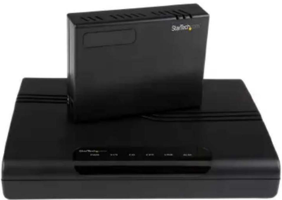
1 Port to 4 Port 10/100Mbps VDSL2 Ethernet Extender Kit over Single Pair Wire – 1 km
410VDSLEXT2
natural_image
Black StarTech device with a rectangular box and control panel (no visible text or symbols on the device body)*actual product may vary from photos
For the most up-to-date information, please visit: www.startech.com
FCC Compliance Statement
This equipment has been tested and found to comply with the limits for a Class B digital device, pursuant to part 15 of the FCC Rules. These limits are designed to provide reasonable protection against harmful interference in a residential installation. This equipment generates, uses and can radiate radio frequency energy and, if not installed and used in accordance with the instructions, may cause harmful interference to radio communications. However, there is no guarantee that interference will not occur in a particular installation. If this equipment does cause harmful interference to radio or television reception, which can be determined by turning the equipment off and on, the user is encouraged to try to correct the interference by one or more of the following measures:
- Reorient or relocate the receiving antenna.
- Increase the separation between the equipment and receiver.
- Connect the equipment into an outlet on a circuit different from that to which the receiver is connected.
- Consult the dealer or an experienced radio/TV technician for help
This device complies with part 15 of the FCC Rules. Operation is subject to the following two conditions: (1) This device may not cause harmful interference, and (2) this device must accept any interference received, including interference that may cause undesired operation.
Changes or modifications not expressly approved by StarTech.com could void the user's authority to operate the equipment.
Industry Canada Statement
This Class B digital apparatus complies with Canadian ICES-003.
Use of Trademarks, Registered Trademarks, and other Protected Names and Symbols
This manual may make reference to trademarks, registered trademarks, and other protected names and/or symbols of third-party companies not related in any way to StarTech.com. Where they occur these references are for illustrative purposes only and do not represent an endorsement of a product or service by StarTech.com, or an endorsement of the product(s) to which this manual applies by the third-party company in question. Regardless of any direct acknowledgement elsewhere in the body of this document, StarTech.com hereby acknowledges that all trademarks, registered trademarks, service marks, and other protected names and/or symbols contained in this manual and related documents are the property of their respective holders.
Table of Contents
Introduction....1
Packaging Contents .... 1
System Requirements....1
Product Overview ...... 2
Installation 4
Hardware Installation ....4
DIP Switch Settings - Transmitter ....5
Configuration....7
Web Interface 7
Welcome Screen....7
System......8
Port Management....11
VLAN 14
QoS Setting 16
Security Filter....19
VDSL Setting 20
Connector Architecture 22
Resetting Your Device....23
Appendix....23
Technical Support 25
Warranty Information....25
Introduction
Packaging Contents
• 1x 1 Port VDSL2 Ethernet Transmitter
• 1x 4 Port VDSL2 Ethernet Receiver
• 2x Universal Power Adapters (NA/UK/EU)
• 1x RJ45 to VDSL2 Cable
- 1x RJ11 Cable
- 1x Instruction CD
• 1x Instruction Manual
System Requirements
• 10/100 Mbps Ethernet Network
• Available AC electrical outlets
• RJ11 Cable or RJ11 lines in building infrastructure
Product Overview
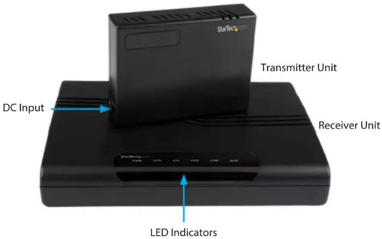
Front / Side View
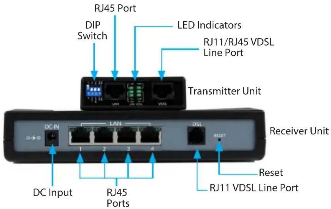
Rear View
LED Displays
Transmitter Unit
LAN LED Display
LED Blinking ON OFF
1 Activity Link up Link down
2 100 Mbps 10 Mbps
3 Full duplex Half duplex
VDSL LED Display
| LED Blinking ON OFF | |||
| 1 Activity | Device Power On | Device Power Off | |
| 2 | - | CPE Mode CO Mode | |
| 3 | Slowly: Idle Quickly: Training | Linked Offline | |
Receiver Unit
| LED Blinking | ON | OFF | |
| PWR | Device Power On | Device Power Off | |
| SYS | System Activated | System Running | |
| CO | CO Mode On | ||
| CPE | CPE Mode On | ||
| LINK | Activity | ||
| Slowly: Start Connection Quickly: Data Transmit | Linked | ||
| ALM | Connection Error | ||
Installation
Hardware Installation
Transmitter Unit
- Connect the provided power adapter from an AC electrical outlet to the DC Input on the Transmitter Unit. The "PWR" LED should light up solid.
- Set all four of the DIP switches to the upward (OFF) position. This places the unit in CO mode.
- Connect an RJ45 Ethernet cable to the RJ45 LAN Port on the Transmitter Unit.
- Connect the other end of the Ethernet cable into your Ethernet network device (eg: switch, Ethernet modem).
- Connect an RJ11 phone cable into the VDSL Port on the Transmitter Unit.
- Connect the opposite end of the RJ11 cable to the DSL Port on the Receiver Unit (or to your buildings RJ11 phone line infrastructure, depending on your setup).
Optional: Configure DIP switches 2 through 4 as necessary (see "DIP Switch Settings" section below).
Receiver Unit
- Place the Receiver Unit at the end-point location.
- Connect the provided power adapter from an AC electrical outlet to the DC Input on the Receiver Unit. The "PWR" and "SYS" LED should light up solid.
- If not previously completed, connect the RJ11 cable that was inserted into the RJ11 VDSL Port on the Transmitter Unit directly to the DSL Port on the Receiver Unit (or from your buildings existing RJ11 analog telephone wiring, depending on the setup from step 6 above.
- If the Transmitter and Receiver Units are able to successfully communicate with each other, the "LINK" LED should light up solid.
- Connect each computer or Ethernet networking device to an available RJ45 Port on the Receiver Unit. The respective "LAN" LED on each individual RJ45 Port should light up to indicate a successful physical connection.
DIP Switch Settings - Transmitter
The Transmitter Unit has a 4-position DIP switch for configuration of Side, Channel, Rate Limit, and SNR.
For initial setup, DIP switch 1 is usually set to the upward (OFF) position, ensuring the unit is set to CO mode (Receiver Unit set to CPE mode by default).
When using the 410VDSLEXT2, one end (Transmitter or Receiver) must always be set to "CO" mode, while the opposite end must always be set to "CPE" mode.
Setting each unit to CO or CPE mode is usually based on which direction you want the most bandwidth delivered. "Download" bandwidth, data sent from CO to CPE, is generally higher than "Upload" bandwidth from CPE to CO.
- If you need higher bandwidth from the Transmitter Unit to the Receiver Unit, set DIP switch 1 to the upward (OFF) position.
- If you need higher bandwidth from the Receiver Unit to the Transmitter Unit, set DIP switch 1 to the downward (ON) position.
See the "Configuration → Mode Select" section below to set the Receiver Unit to the appropriate CO or CPE mode based on the mode that was set on the Transmitter Units DIP Switch setting.
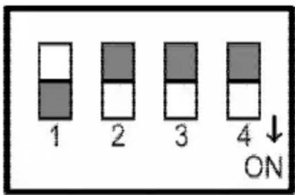
Pin 1 - CO, CPE Switch
OFF: If Pin 1 is in the OFF position, the Transmitter Unit will operate in Central Office (CO) mode.
ON: If Pin 1 is in the ON position, the Transmitter Unit will operate in Customer Premise Equipment (CPE) mode.
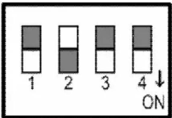
Pin 2 - Interleave Noise Protection
StarTech.com
OFF: If Pin 2 is in the OFF position, the Transmitter Unit will operate in Interleave mode, with communication protection for up to 250ms of impulse noise with latency less than 6 ms
ON: If Pin 2 is in the ON position, the Transmitter Unit will operate in Fast mode, with direct data transmissions having less than 1ms of latency.
Pin 3 - Band Plan
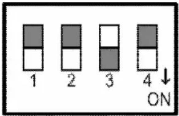
OFF: If Pin 3 is in the OFF position, the Transmitter Unit will operate in Symmetric mode, with both downstream and upstream transmissions operating on the G.997 band plan.
ON: If Pin 3 is in the ON position, the Transmitter Unit will operate in Asymmetric mode, with asymmetric short range transmissions operating at the highest available line rate.
Pin 4 - General Protection
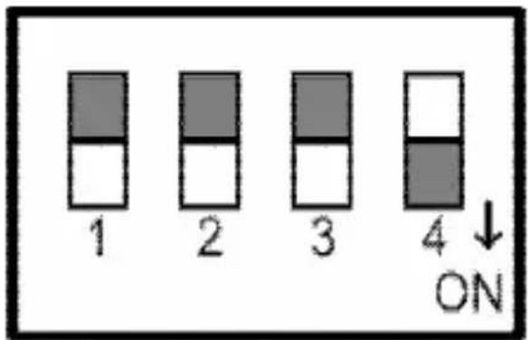
OFF: If Pin 4 is in the OFF position, the Transmitter Unit will operate with a SNR ratio up to 9 dB.
ON: If Pin 4 is in the ON position, the Transmitter Unit will operate with a SNR ratio of 6 dB.
Configuration
Web Interface
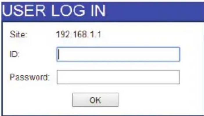
The Receiver Unit has a built-in web interface for configuring the settings. There is no software installation required. To access the Web Interface, open a web browser (Internet Explorer, Chrome, Firefox, etc.), and navigate to "http://192.168.1.1"
Note: If you had previously changed the IP address, login to the modified IP address.
You will then see a login page. Login to the system with your user name and password.
The default login information is:
ID: admin
Password: admin
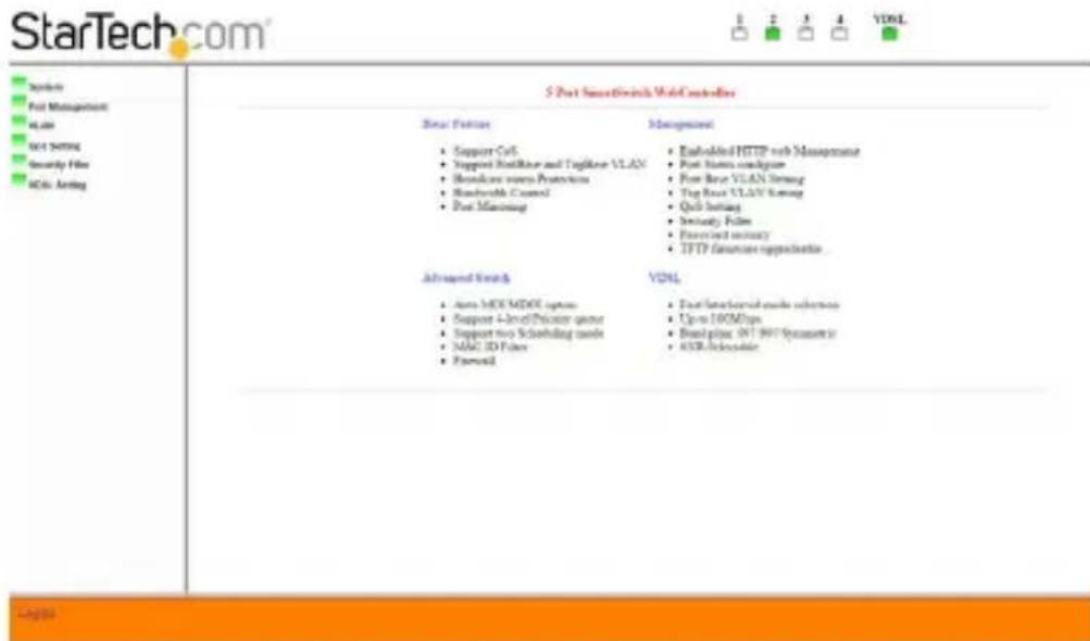
Welcome Screen
After you complete the login process, a main page will be shown. There are five square icons at the top-right of the web interface that show the current port status.
Management options are shown on the left side of the web interface. Click on each heading to customize your 410VDSLEXT2.
System
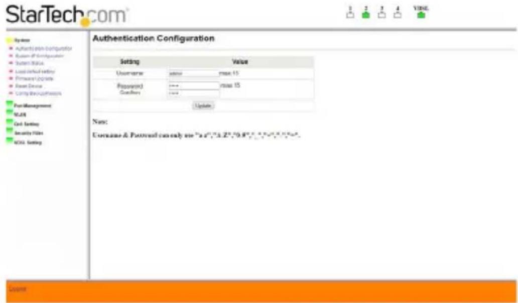
Authentication Configuration
Change your login name and password in this area. Press the "Update" button to save your changes.
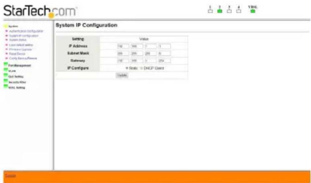
System IP Configuration
Set your IP configuration settings, including IP address, subnet mask and gateway.
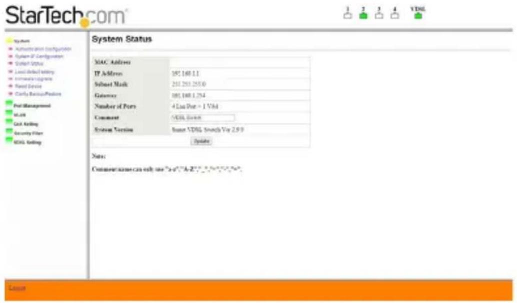
System Status
Review hardware and software information and update device description in the "Comment" field if desired.
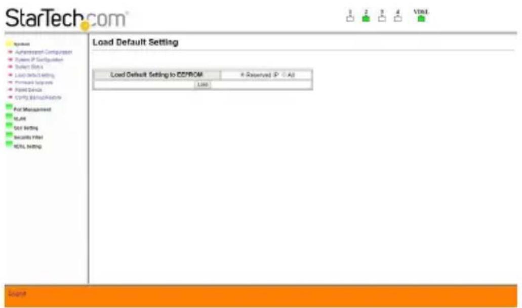
Load Default Setting
Provides two methods to restore the 410VDSLEXT2 to default settings.
- Reserved IP: Allows you to reload the default factory settings without changing your IP address.
- All: All settings will be restored to the original default settings, including IP address. Once you choose a method, press the "Load" button to activate.
Update the Firmware
Warning! When you start this process, you will erase the firmware currently loaded on your device. If the process fails to complete, your device may not function.
- Navigate to www.StarTech.com and download the latest firmware.
Reset Device
Restarts the 410VDSLEXT2. Click on "Confirm" to restart.
![StarTech.com System • Authentication Configurations • System IP Configurations • System IP User • Local/Regional Setting • Software Updates • Rapid Device • Comb Control/Reversal Port Management SLAR Test Setting Security Info! MOS Setting Reset Device Click "Confirm" to Reset the Device [Cancel]](/content/2026/05/960570/images/7f9cd55526219af872bd24f8209f1af8a3fa09e71b4e64b7e9a2bcf3357ac191.jpg)
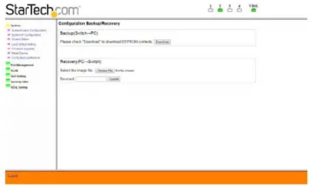
Configuration Backup/ Restore
To create a backup of your settings, click the "Download" button and a pop-up will display, letting you choose a location to save a backup file.
To recovery a backup, click the "Choose File" button and choose which file to restore from. Enter your password and click on the "Update" button to start the restore process.
Port Management
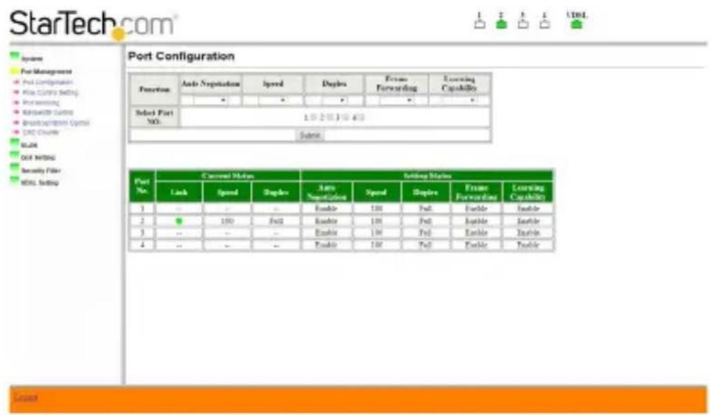
Port Configuration
Set port configurations and select which ports to apply these settings to. Select all four ports to apply each port with the same settings. Press the "Submit" button to apply the new settings. All information will be updated in the displayed status table.
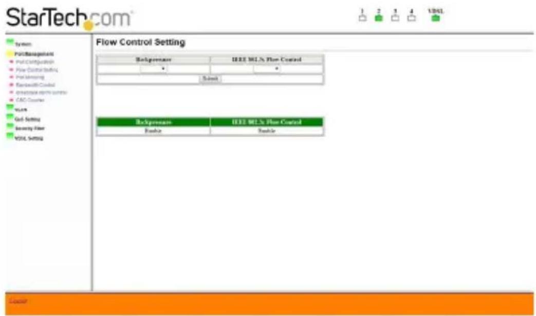
Flow Control Setting
Choose to Enable or Disable "Backpressure" and/or "IEEE 802.3x Flow Control". Click the "Submit" button to save your settings.
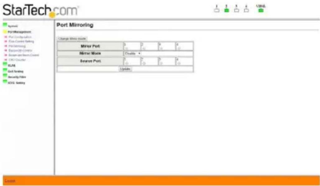
Port Mirroring
Choose to mirror configurations using two settings, click on "Change Mirror Mode" button to change your mirror setup style.
In order to use the port mirroring function, you will need the following information:
- Mirror Port: Select a mirror port to monitor the traffic source.
- Mirror Mode: Modes 1 and 2
• Disable: Port mirroring function is disabled.
- Rx: Copy the incoming packets of the selected source port to the selected mirror port.
- Tx: Copy the outgoing packets of the selected source port to the selected mirror port.
- Tx&Rx: Copy both incoming and outgoing packets from the selected source port to the selected mirror port.
- Mirror source-destination pair: Tx port and Rx port must be different ports.
-
Source Port: The source port traffic which will be copied to the mirror port.
-
Destination Port: Only available in Mode 2.
Mode 1
Has four "Mirror Mode" options: Disable, Rx, Tx, and Tx&Rx. In this mode, select your "Mirror Port Number," "Source Port Number," and "Mirror Mode." Click the "Update" button to save your settings.
Mode 2
Has two "Mirror Mode" options: Disable or Mirror source-destination pair. In addition, you need to choose your "Destination Port" and "Source Port." Click the "Update" button to save your settings.
Bandwidth Control
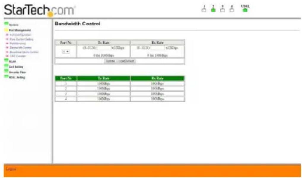
Set bandwidth control on individual ports. Select the port that you wish to control, and then enter the Tx and Rx rates. Click on the "Update" button to save the settings you've entered, or click on the "Load Default" button to restore settings to the default value for the selected port. Once settings are saved, the table will show the current values set up for each port.
Broadcast Storm Control
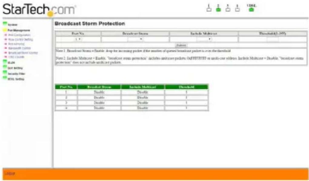
This section lets you block excessive broadcast packets. Choose which port you wish to enable protection. Select Enable for the “Broadcast Storm” option to enable this function, and enter a value for “Threshold”. Broadcast packets will be dropped when the number is more than entered threshold value.
CRC Counter
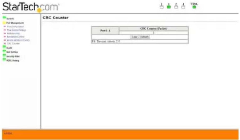
Displays the number of CRC errors while the 410VDSLEXT2 is active. Click the "Clear" button to reset the counter and the "Refresh" button to update the latest counter information.
VLAN
The 410VDSLEXT2 provides two options for VLAN setup. By "Port Base" or by "Tag Base." If you choose to set up VLAN based on Port, the settings in Tag Base will not be activated.
Port Base VLAN
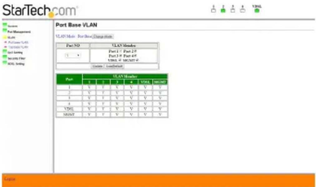
Ensure your "VLAN Mode" is correct. If incorrect, click the "Change Mode" button to switch VLAN mode.
Choose "Port NO" first, and then select which port should be in the VLAN member. Click on the "Update" button to save your changes, and click on the "LoadDefault" button to restore the default value. All current/updated information will be shown in the table.
Tag Base VLAN
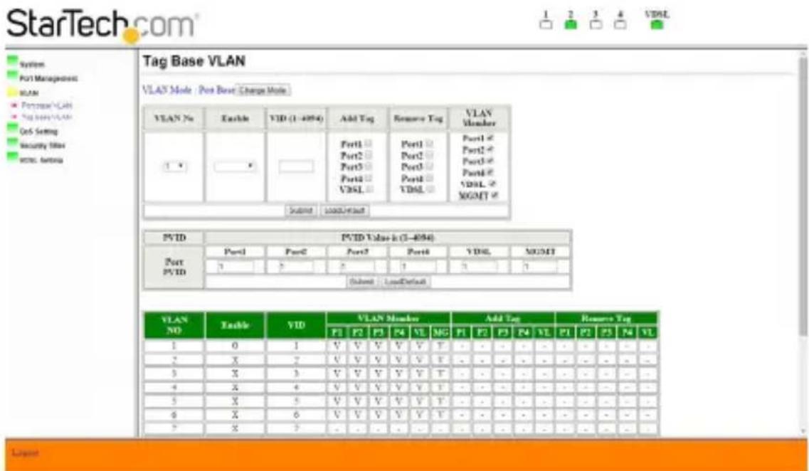
Select "Tag Base" from the "VLAN Mode" using the "Change Mode" button as need.
In Setup Area 1, you can choose the VLAN number, and which port you want to add or remove a tag. In addition, you can check all the VLAN members you wish to have in this VLAN number.
Click on the "Submit" button to save your changes.
A message box saying "Control port will not be able to connect devices" may be displayed due to some receivers not recognizing VLAN tagging, so you may be not able to connect to a tagged port.
In Setup Area 2, you can set the PVID of each port. If your PVID is invalid, a warning message "Invalid VLAN status" will be shown.
QoS Setting
Priority Classification
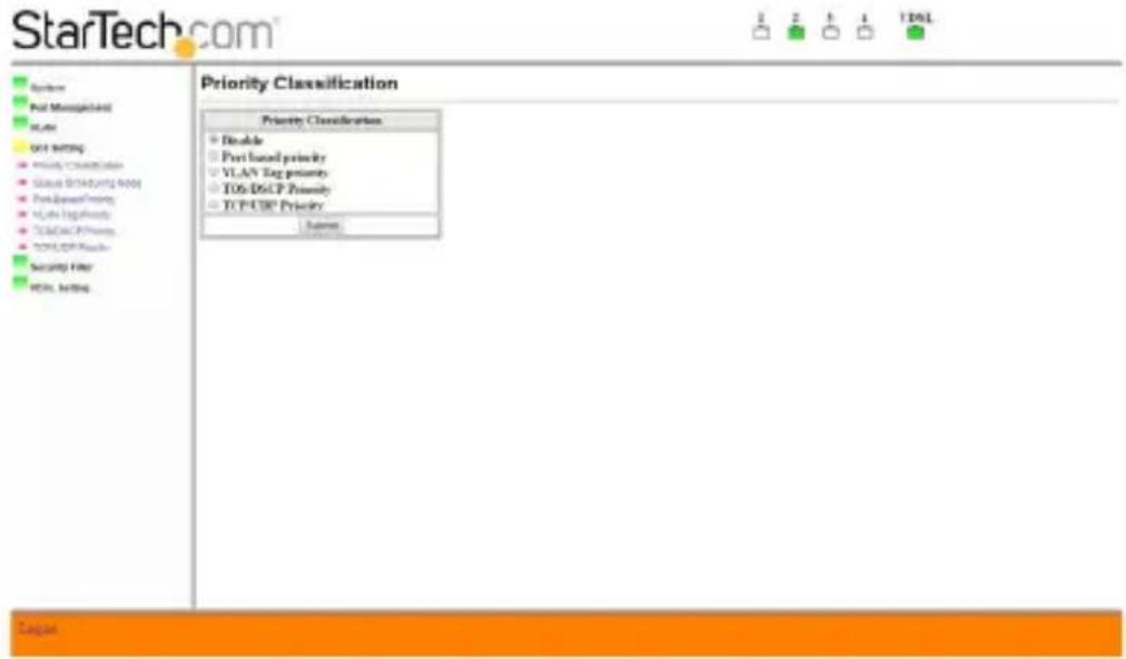
Enable QoS function based on the selected priority mode. If you need to start QoS function, please make sure you visit this page first and enable the priority mode you wish to apply; otherwise, the QoS function will not be activated.
Queue Scheduling Mode
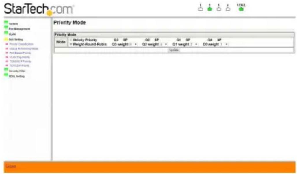
There are two modes in "Queue Scheduling Mode":
-
Strictly Priority: Services the queues based on priority only. As traffic comes into the modem, traffic on the highest priority queue, Q3 is transmitted first. When that queue empties, traffic on the next highest-priority queue, Q2 are transmitted until Q2 empties, and then traffic is transmitted on Q1 and so on. If a higher priority queue is never empty, then traffic on the lower priority will not be sent. The SP class is typically for video applications that require a fixed amount of bandwidth to be considered for good quality.
-
Weight-Round-Robin: Services on a rotating basis and is activated only when a port has more traffic than it can handle. A queue is given an amount of bandwidth irrespective of the incoming traffic on that port. The queue then moves to the back of the list. The next queue is given an equal amount of bandwidth, and then moves to the end of the list, and so on, depending on the number of queues being used. This works in a looping fashion until a queue is empty.
Choose what kind of algorithm you wish to apply and press the "Update" button to save the settings.
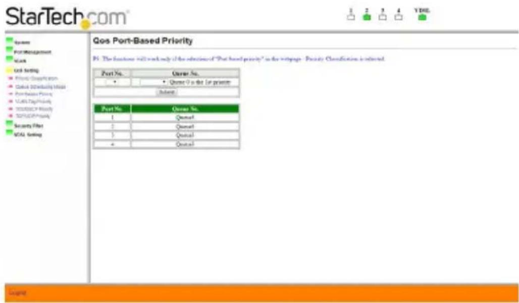
Port-Based Priority
Two items should be selected in order to set this priority up.
- Port number: Choose the port number you wish to apply this policy.
- Queue number: Choose which queue you wish the selected port to belong to.
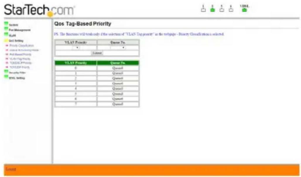
VLAN Tag Priority
You can assign VLAN priority and its corresponding queue number in this section.
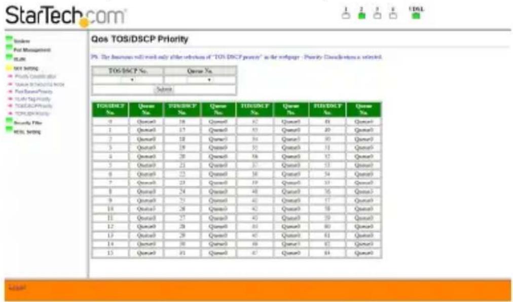
TOS/DSCP Priority
You can assign a queue with a DSCP priority. Click on the "Submit" button and the information will be saved and updated to the table below.
Note: In order to allow QoS running TOS/DSCP priority, make sure you change the "Priority Classification" option to "TOS/DSCP Priority" first.
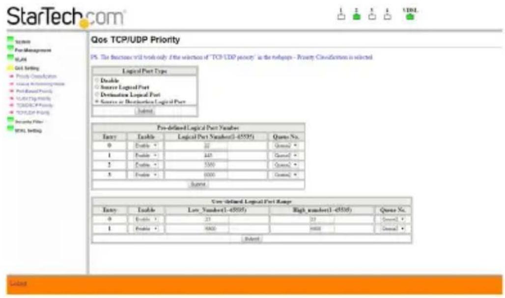
TCP/UDP Priority
First, choose the "Logical Port Type" and press the "Submit" button to start this function. Then, if you want to run this priority based on pre-defined logical port, assign the "Pre-defined Logical Port Number" entry and click on the "Submit" button to save the changes.
If you want to activate this priority by user-defined logical port, you need to assign the "User-defined Logical Port Range" section and press the "Submit" button to save your modifications.
Note: In order to allow QoS running TCP/UDP priority, make sure you change the "Priority Classification" option to "TCP/UDP Priority" first.
Security Filter
MAC ID Filter
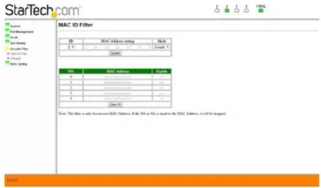
Five MAC addresses can be stored in the "MAC ID Filter". Choose which entry number you wish to save the MAC and enter the MAC address in the "MAC Address setting" field, as well as its mode.
The below table is then updated to display the MAC address you just saved. If you wish to remove all the MAC addresses in the table, click on the "Clear All" button to remove every address.
Firewall
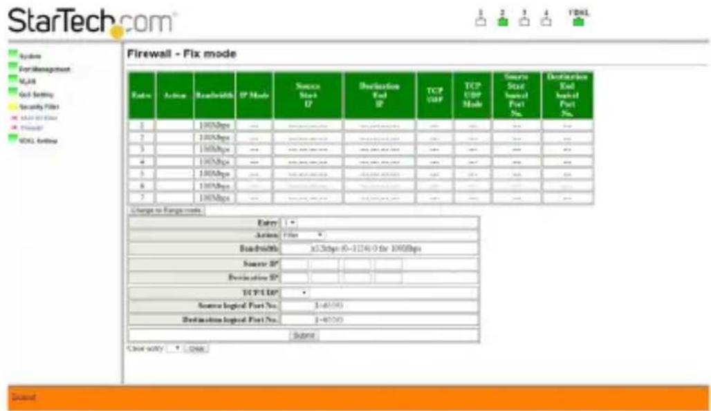
In this section, you can modify data traffic to provide greater bandwidth control to specified IP addresses. You can assign settings to either a specific IP address or to a range of IP addresses, letting you control, forward, and filter data packets to the IP addresses specified.
Specific IP Address: Choose which entry you wish to add this set of data. In this mode, you need to provide specific IP addresses. Click "Submit" once you finish your modification.
IP Address Range: Click on the "Change to Range Mode" button to switch edit sections. Then set a range of IP addresses by entering the "start" IP address and the "end" IP address.
VDSL Setting
Port Setting
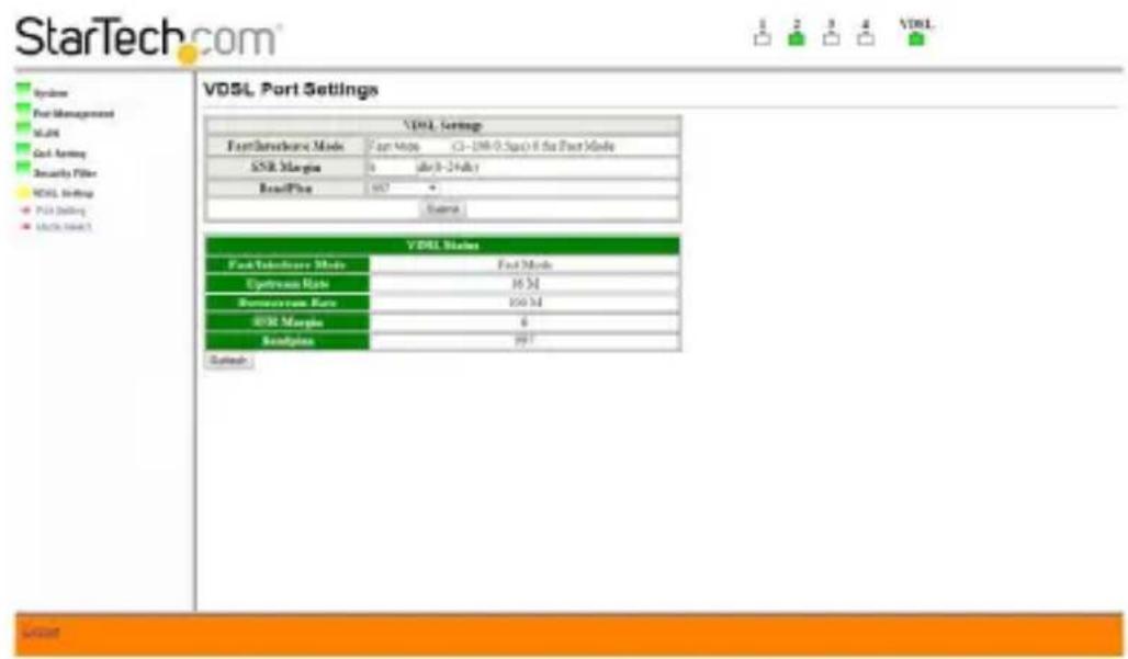
In this section, you can change VDSL port settings. After you change the settings, click the "Submit" button to update the 410VDSLEXT2. Click the "Refresh" button to get the latest status information.
Mode Select
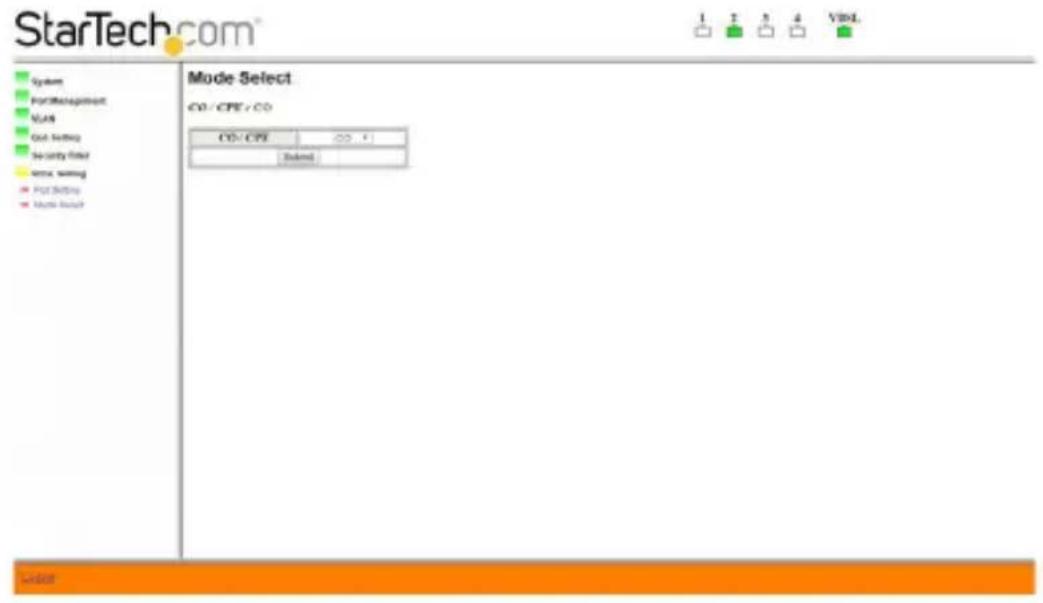
In this section, you must set the Receiver to CO (Central Office), or CPE (Customer Premises Equipment) operating modes. Select the Receiver mode, and once selected, click the "Submit" button to save the changes.
When using the 410VDSLEXT2, one end (Transmitter or Receiver) must always be set to "CO" mode, while the opposite end must always be set to "CPE" mode.
Setting each unit to CO or CPE mode is usually based on which direction you want the most bandwidth delivered. "Download" bandwidth, data sent from CO to CPE, is generally higher than "Upload" bandwidth from CPE to CO.
- If you need higher bandwidth from the Transmitter Unit to the Receiver Unit, set the mode to CPE.
- If you need higher bandwidth from the Receiver Unit to the Transmitter Unit, set the mode to CO.
Note: This setting will restart the 410VDSLEXT2
See the "DIP Switch Settings" section above to set the Transmitter Unit to the appropriate CO or CPE mode based on the mode set for the Receiver Unit.
Connector Architecture
Ethernet Ports
The RJ45 Ethernet Port interface is an 8-pin modular jack. The table below displays the pinout assignments.
Pin Number Assignment (MDI-X)
| 1 RX+; Receive data + |
| 2 RX-; Receive data - |
| 3 TX+; Transmit data + |
| 4 Not used |
| 5 Not used |
| 6 TX-; Transmit Data - |
| 7 Not used |
| 8 Not used |
VDSL Ports
The VDSL Port is standard 8-pin modular jack. The table below displays the pinout assignments.
Pin Number Assignment (MDI-X)
| 1 Not used |
| 2 Not used |
| 3 Not used |
| 4 ANALOG Input/Output |
| 5 |
| 6 Not used |
| 7 Not used |
| 8 Not used |
ANALOG Input/Output
Resetting Your Device
There is a reset button on the rear of the 410VDSLESXT2 Receiver Unit. Please use a narrow item such as a pencil or paper clip, and gently press the Reset Button for several seconds. This will reset all the configurations and you can login to the web interface using the default IP address, ID, and Password.
Note:
-
Press the button for 2 seconds: Reboots the 410VDSLEXT2 without resetting any configuration settings.
-
Press the button for 8 seconds: Loads the default factory settings and reboots the 410VDSLEXT2.
Appendix
Default IP Address: http://192.168.1.1
Default Login Information: Default login name is "admin" and the password is "admin"
| Term Definition | |
| QoS | Quality of Service |
| Refers to resource reservation control mechanisms rather than the achieved service quality. QoS is the ability to provide different priority to different applications, users, or data flows, or to guarantee a certain level of performance to a data flow. | |
| SNR | Signal-to-noise RatioIs measure used in science and engineering to quantify how much a signal has been corrupted by noise. It is defined as the ratio of signal power to the noise power corrupting the signal. A ratio higher than 1:1 indicates more signal than noise |
| TOS/DSCP | Type of Service/ Diffserv CodepointThis uses the upper six bits in the ToS (Type of Service) byte to mark priority traffic. Hence, there are 64 possible codepoints. |
| VLAN Tagging | VLAN tagging (IEEE 802.1Q) is a networking standard written by the IEEE 802.1 work group allowing multiple bridged networks to transparently share the same physical network link without leakage of information between networks. VLAN tagging defines the meaning of a Virtual LAN (VLAN) with respect to the specific conceptual model underpinning bridging at the MAC layer and to the IEEE 802.1D spanning tree protocol. This protocol allows for individual VLANs to communicate with one another with the use of a switch with Layer-3 capabilities, or a router. |
Technical Support
StarTech.com's lifetime technical support is an integral part of our commitment to provide industry-leading solutions. If you ever need help with your product, visit www.startech.com/support and access our comprehensive selection of online tools, documentation, and downloads.
For the latest drivers/software, please visit www.startech.com/downloads
Warranty Information
This product is backed by a two year warranty.
In addition, StarTech.com warrants its products against defects in materials and workmanship for the periods noted, following the initial date of purchase. During this period, the products may be returned for repair, or replacement with equivalent products at our discretion. The warranty covers parts and labor costs only. StarTech.com does not warrant its products from defects or damages arising from misuse, abuse, alteration, or normal wear and tear.
Limitation of Liability
In no event shall the liability of StarTech.com Ltd. and StarTech.com USA LLP (or their officers, directors, employees or agents) for any damages (whether direct or indirect, special, punitive, incidental, consequential, or otherwise), loss of profits, loss of business, or any pecuniary loss, arising out of or related to the use of the product exceed the actual price paid for the product. Some states do not allow the exclusion or limitation of incidental or consequential damages. If such laws apply, the limitations or exclusions contained in this statement may not apply to you.
Hard-to-find made easy. At StarTech.com, that isn't a slogan. It's a promise.
StarTech.com is your one-stop source for every connectivity part you need. From the latest technology to legacy products — and all the parts that bridge the old and new — we can help you find the parts that connect your solutions.
We make it easy to locate the parts, and we quickly deliver them wherever they need to go. Just talk to one of our tech advisors or visit our website. You'll be connected to the products you need in no time.
Visit www.startech.com for complete information on all StarTech.com products and to access exclusive resources and time-saving tools.
StarTech.com is an ISO 9001 Registered manufacturer of connectivity and technology parts. StarTech.com was founded in 1985 and has operations in the United States, Canada, the United Kingdom and Taiwan servicing a worldwide market.
- Port to 4 Port 10/100Mbps VDSL2 Ethernet Extender Kit over Single Pair Wire – 1 km
- FCC Compliance Statement
- Industry Canada Statement
- Use of Trademarks, Registered Trademarks, and other Protected Names and Symbols
- Table of Contents
- Introduction....1
- Product Overview ...... 2
- Installation 4
- DIP Switch Settings - Transmitter ....5
- Configuration....7
- Technical Support 25
- Warranty Information....25
- Introduction
- Packaging Contents
- System Requirements
- Product Overview
- LED Displays
- Transmitter Unit
- LED Blinking ON OFF
- Installation
- Hardware Installation
- Receiver Unit
- DIP Switch Settings - Transmitter
- Pin 1 - CO, CPE Switch
- Pin 2 - Interleave Noise Protection
- Configuration
- Web Interface
- The default login information is:
- Welcome Screen
- System
- Authentication Configuration
- System IP Configuration
- System Status
- Load Default Setting
- Update the Firmware
- Reset Device
- Configuration Backup/ Restore
- Port Management
- Port Configuration
- Flow Control Setting
- Port Mirroring
- Mode 1
- Mode 2
- Bandwidth Control
- Broadcast Storm Control
- CRC Counter
- VLAN
- Port Base VLAN
- Tag Base VLAN
- QoS Setting
- Priority Classification
- Queue Scheduling Mode
- Port-Based Priority
- VLAN Tag Priority
- TOS/DSCP Priority
- TCP/UDP Priority
- Security Filter
- MAC ID Filter
- Firewall
- VDSL Setting
- Port Setting
- Mode Select
- Note: This setting will restart the 410VDSLEXT2
- Connector Architecture
- Ethernet Ports
- VDSL Ports
- Resetting Your Device
- Note:
- Appendix
- Technical Support
- Warranty Information
- Limitation of Liability
Brand : StarTech.com
Model : 410VDSLEXT2
Category : Wi-Fi repeater