
KHGG700 - Cooker KELVINATOR - Free user manual and instructions
Find the device manual for free KHGG700 KELVINATOR in PDF.


| Product Type | Gas Built-in Hob |
| Model | KHGG700 (also compatible with KHG750SS, KHGG600, KHGG900, KHG640SS, KHG940SS, KHG750SS) |
| Number of Burners | 4 (including Triple Flame burner) |
| Burner Types | Small Auxiliary (1.00 kW max), Medium Semi-rapid (1.75 kW max), Large Rapid (3.0 kW max), Triple Flame (3.80 kW max) |
| Gas Supply | Natural Gas G20 20 mbar or LPG G30/G31 20-30/37 mbar, G30 50 mbar |
| Gas Connection | G1/2" male thread |
| Electrical Supply | AC 220-240V 50/60Hz (for ignition and safety valves) or DC 1.5V battery (for ignition) |
| Ignition | Automatic integrated ignition with thermocouple safety device |
| Safety Features | Thermocouple flame failure device, automatic gas cut-off if flame goes out |
| Installation Type | Built-in in kitchen units up to 600mm depth |
| Installation Clearances | Side panels taller than hob must be at least 150 mm from opening; wall cabinets or extractor hoods at least 650 mm above hob |
| Burner Diameter Range | Small: 80-160 mm, Medium: 120-200 mm, Large: 180-220 mm, Triple Flame: 220-260 mm |
| Material | Enameled parts (burner caps, flame caps, pan stands) |
| Cleaning | Wash with lukewarm water and mild detergent; avoid abrasives, steel wool, bleach; pan stands dishwasher safe |
| Maintenance | Periodic check of gas pipe and pressure regulator; tap lubrication by qualified staff |
| Spare Parts | Original spare parts available through authorized service centers |
| Warranty | Full warranty conditions provided in leaflet; keep purchase receipt |
| Environmental Compliance | Materials recyclable; dispose via separate waste collection |
| Directives | Complies with EEC 73/23, 89/336, 90/396, 93/68 and amendments |
Frequently Asked Questions - KHGG700 KELVINATOR
User questions about KHGG700 KELVINATOR
0 question about this device. Answer the ones you know or ask your own.
Ask a new question about this device
Download the instructions for your Cooker in PDF format for free! Find your manual KHGG700 - KELVINATOR and take your electronic device back in hand. On this page are published all the documents necessary for the use of your device. KHGG700 by KELVINATOR.
USER MANUAL KHGG700 KELVINATOR
Gas Built in Hob
KHG750SS / KHGG600 / KHGG700 / KHGG900
KHG640SS / KHG940SS / KHG750SS
User and Installation Instruction

For Your Safety
These instructions have been drawn up for your safety and that of others. You are therefore requested to read them carefully before installing and using the appliance. Keep this instruction manual for future reference as necessary. If the appliance is sold of moved, make sure that the manual is handed over to the new user.
Installation
- Installation of the appliance and its connection to the electrical mains must only be carried out by QUALIFIED STAFF. Before any procedure, it is important to check that the appliance is DISCONNECTED from the electrical mails.
- It is risky to modify or attempt to modify the characteristics of this product.
• After removing the appliance from the packaging, make sure that it is undamaged and that the electrical lead is in perfect condition. Otherwise, contact your dealer before putting the appliance into operation.
• The Manufacturer declines all responsibility in case of failure to comply with the accident prevention regulations.
* Make sure that air is able to circulate freely around the appliance. Poor ventilation produced a shortage of oxygen
• Make sure that the appliance is supplied with the type of gas indicated on the relative sticker next to the mains gas connection pipe. - Use of a gas cooking appliance produces heat and moisture in the room in which it is installed. Ensure that the room is well ventilated by keeping the air intakes open and in good working order or by installing an extractor hood with discharge pipe.
- If the appliance is used intensively for a long time the effectiveness of the ventilation will have to be increased, for example by opening a window or increasing the power of any electric extractor fan.
During use
This product is designed to cook foods inside ordinary homes and for non-professional purposes. It should not be used for any other purpose.
- After using the appliance, make sure that all controls are in "CLOSED" or "OFF" position.
- If you use an electrical socket close to this appliance, take care that the cables of the appliances you are using do not touch it and are far enough away from the hot parts of this appliance.
Children's safety
- This appliance must only be used by adults. Make sure that children do not touch the controls or play with the appliance.
• The exposed parts of this appliance heat up during cooking and remain hot for some time even after it is switched off. Keep children well away until the appliance has cooled down.
Cleaning and maintenance
- Keep the appliance thoroughly cleaned. Food residues may cause fire risks.
Service and parts
- In the instance of malfunctions. Never attempt to repair the appliance yourself. Repairs by unskilled persons may cause damage and accidents. First refer to the contents of this manual. If you do not find the necessary information, contact your nearest Service Centre, Servicing work on this appliance must be carried out by an authorized Technical Service Centre. Always request the use of original spare parts.
Environmental protection advice
- All the materials used are environmentally compatible and recyclable. Please make your contribution to conserving the environment by using the separate waste collection channels available.
Decommissioned appliances
- Appliances which are no longer used or usable are not worthless waste. Through environment-friendly disposal, a number of materials used in the production of your appliance can be recovered.
- Find out about the current disposal options from your specialist dealer, or your local authority.
- Before scrapping the appliances, cut the power supply lead and make it unusable.
Contents
For the User
For your safety....
Description of the hob....
Instructions for use
Cleaning and maintenance.... 6
For The Installation Technician
Technical data
Instructions for the installation technician....8
Electrical connection 9
Adapting to the different types of gas
Building into fitted kitchen units.... 13
Guide to reading the instructions
The following symbols will help you
When reading the instructions:

Safety information

"Step by step" instructions

Suggestions and Advice

Information concerning environmental protection

This appliance complies with the following EEC Directives:
73/23 and 90/683 (relating to Low Voltage);
- 89/336 (relating to Electromagnetic Compatibility);
- 90/396 (relating to Gas Appliances);
- 93/68 (relating to the General Standards)
And subsequent amendments.
Description of the hob

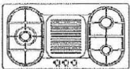
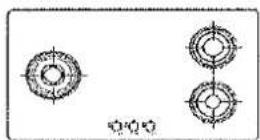
1
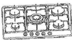
1.Hob
2. Small auxiliary burner
3. Medium semi-rapid burner
4. Large rapid burner
5.Triple flame burner
6.Burner control knobs
7.Hot plate
6. Indicator tight
Instructions for use
The hob control knobs
The symbols on the control knobs mean the following:
no gas flow
maximum gas flow
Minimum gas flow
All operating positions must be set between the maximum and minimum flow settings, and never between the maximum setting and the closed position.
(Symbol present on version with lighting integrated in the Control knob)
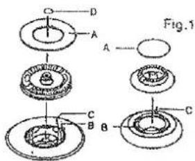
A-Burner cap
B-Lighting plug
C-Thermocouple
D-Triple flame cap
Dual triple flame version
no gas flow
maximum gas flow from central burner
minimum gas flow from central burner
maximum gas flow from outer and central burners simultaneously
minimum gas flow from outer and central burners simultaneously
Lighting the burners

To obtain a flame more easily, light the burner before placing a cooking utensil on the pan stand

To light a burner, proceed as follow: for Version with lighting integrated in the
control knob push the knob of the burner fully down and turn it anticlockwise
to the "maximum flow" setting symbol, or press the button if the appliance has individual lighting.

After lighting the flame, keep the knob pressed for about 10 seconds: this time is necessary to heat up the "thermocouple"(Fig.1-C) and activate the safety valve, which would otherwise cut off the gas flow.

Then check that the flame is even and turn the control knob to adjust the flame as required
In the instance of a power cut, place a flame near the burner and proceed as already described.
If the flame does not light after a few attempts, check that the "burner cap" and "flame cap" are correctly positioned.
To turn off the flame, turn the control knob clockwise to the Ⓞ symbol.
Before removing pans from the burners, always lower or turn off the flame.
For correct use of the hob
For lower gas consumption and better efficiency. Use only flat-bottomed pans of dimensions suitable for the burners, as shown in the table on the right. Also, as soon as a liquid comes to the boil take care to turn the flame down to a level that will just keep it boiling.
| Burner | minimum diameter | maximum diameter |
| Large(rapid) | 180mm | 220mm |
| Medium(semi-rapid) | 120mm | 200mm |
| Small(Auxiliary) | 80mm | 160mm |
| Triple Flame | 220mm | 260mm |

During cooking processes involving fats or oils, watch your foods carefully
because these substances may catch fire if brought to high temperatures.
Cleaning and maintenance
Before each operation, disconnect the appliance from the electrical mains and allow it to cool down.
General cleaning
Wash enameled parts with lukewarm water and detergent: do not use abrasive products which might damage them.
Wash the flame caps and burner caps often with boiling water and detergent, taking care to remove all deposits
The hob pan stands can also be washed in a dishwasher
For stubborn dirt, use ordinary non-abrasive detergents or specific commercial products. We strongly advise you not to use scouring pads. Steel wool or acids for cleaning.
Hob
Clean the hob regularly with a soft cloth wet with lukewarm water and a little liquid detergent. Do not use the following products:
- household detergents or bleaches;
- soaped scouring pads not suitable for non-stick utensils;
- steel wool scouring pads;
- stain removers for baths or sinks.
If the hob gets very dirty, use specific commercial products.
Ignition plug
Automatic burner ignition is provided (when installed) by a ceramic "plug" and a metal electrode (B in fig.1). Periodically clean these parts of the hob thoroughly. In addition, to avoid ignition difficulties, check that the cavities in the burner are not
obstructed.
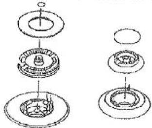
To remove deposits from the burner cavities, remove the cap and separate the two parts (see diagram on the right). After cleaning, put the two parts back together and return them correctly to their position. After washing, replace the hob pan stands, checking that they are correctly positioned.
natural_image
Technical line drawing of a mechanical assembly with multiple circular components and internal features (no text or symbols)Routine maintenance
Have the condition and efficiency of the gas pipe and the pressure regulator(if installed) checked periodically. If anomalies are found, do not repairs but have the faulty part replaced.
To ensure good performance and safety, the gas regulator taps must be greased periodically.

Periodic lubrication of the taps must only be carried out by qualified staff, who must also be contacted if the appliance malfunctions.
Service and parts
Before leaving the factory, this appliance was tested and adjusted by specialist skilled staff to give the best operating results. Any subsequent necessary repairs or adjustments must be carried out with the greatest care and attention.
For this reason, we strongly advise you always to contact the Dealer who sold you the appliance or our nearest Service Centre, specifying the nature of the problem, the model of the equipment(Mod.), the product number(Prod. No.) and the serial number(Ser. No.). These data are provided in the plate on the cover of this manual. Always request the use of original spare parts.
Warranty conditions
You new appliance is covered by a warranty. The warranty conditions are provided in full in the "Warranty conditions-Service centers" leaflet which you will find inside the appliance
Keep the fiscal receipt or delivery note, either of which documents your purchase of the appliance and provides proof of date of purchase, in a safe place together with the leaflet.
If the After-Sales Service is call in, show these documents to the staff. If this procedure is not followed, the Service-Centre will have no option but to charge for any repairs.
If necessary, you may find your nearest Centre by consulting the" Warranty conditions --Service centers".
Technical Data
| BURNER TYPE | MAX OUTPUT | MIN OUTPUT | G20 20mbar | G30/31 20-30/37mbar | G30 50mbar | |||
| Kw | Kw | Nozzle Making mm | Cons M^3/h | Nozzle Making mm | Cons g/h | Nozzle Making mm | Cons M^3/h | |
| Small Auxiliary burner | 1.00 | 0.30 | 0.70 | 0.095 | 0.50 | 73 | 0.43 | 73 |
| Medium Semi-rapid Burner | 1.75 | 0.65 | 0.97 | 0.157 | 0.65 | 120 | 0.58 | 120 |
| Large rapid burner | 3.0 | 1.0 | 1.15 | 0.286 | 0.85 | 219 | 0.75 | 219 |
| Triple flame burner | 3.80 | 1.30 | 1.35 | 0.35 | 0.97 | 280 | 0.77 | 280 |
| Gas intake connection | G1/2" |
| Electricity supply | AC 220-240v 50/60Hz |
| Battery supply | DC 1.5v |
Instructions for the installation technician

CAUTION: This appliance must only be installed and used in rooms with permanent ventilation to local standards.
Installation of the appliance and its connection to the electrical mains must only be carried out by QUALIFIED STAFF.
Before any procedure, it is important to check that the appliance is DISCONNECTED from the electrical mains. The Manufacturer declines all responsibility for any damage deriving from installation in breach of the regulations in force or from failure to comply with the accident prevention regulations.
Installation premises
For proper operation of a gas appliance, the air necessary for the combustion of the gas must be able to flow into the room naturally. The air must flow into the room directly through openings in the outside walls. These openings must have an unobstructed cross-section must be no less than 2m^3/h for each kw of power(see total)
power in kw on the appliance nameplate).
This opening must be constructed so that it will not be obstructed from indoors or out and placed close to the floor, preferably on the side opposite to that on which the flue gases are discharged. If it is not feasible to provide these openings in the room where the appliance is installed. The necessary air may be taken from an adjacent room, provided that:
• this room is not a bedroom or a hazardous environment;
- this room is not in a vacuum;
- the ventilation between the room where the appliance is installed and the adjacent room is guaranteed by permanent openings.
Discharge of flue gases
Gas cooking appliances must discharge their flue gases through hoods connected directly to flues or the outdoors. If it is not possible to install the hood (fig. B) an electric fan must be installed on the outside wall or the window of the room, provided it is possible for the ventilation opening to be increased in proportion to the delivery rate of the fan (fig. C). For a kitchen, the delivery rate of this electric fan must guarantee an hourly air exchange of 3-5 times its volume. In both instances, the use of flues already used by other appliances to discharge the flue gases is forbidden.

natural_image
Simple line drawing of a kitchen appliance with a gridded base and tiled floor (no text or symbols)

Connection to the gas supply
The gas Connection must be made in accordance with the local standards. When installing fit a safety tap at the end of the pipeline. The appliance leaves the factory tested and set for the type of gas indicated on the plate inside the bottom guard, close to the gas connection pipe. Make sure that the type of gas to be supplied to the appliance is the same as that shown on the plate. Otherwise, follow the instructions provided in the "Adapting to different types of gas" section.
For maximum efficiency and minimum consumption, make sure that the gas supply pressure complies with the values shown in the gas used is different from that specified( or variable ).a suitable pressure regulator must be installed on the supply pipeline.

The union must be fitted on the end of the gas train. Complete with GJ1/2 "threaded nut, fitting the gasket between the components as shown in the illustration. The gaskets must comply with the local standards. Screw the parts together without forcing, fit the union so that it points in the direction required then tighten all parts.
Connection
Make the connection to the gas system using a rigid metal pipe and regulation unions, or with a stainless steel hose complying with the local standard. If metal hoses are used, take care that they do not come into contact with mobile parts and are not crushed. This must also be checked if the hob is to be combined with an oven.
The gas intake connection of the appliance has a "male thread."
When making the connection, take care not to apply stresses of any kind to the appliance.

When the installation is complete, always check that all the unions are absolutely tight using a soapy solution. Never use a flame to make this check.
Electrical connection
The appliance is profited to operate with a power supply voltage of 230V single-phase. The connection must be made in accordance with the regulations and laws in force.
Before making the connection, make sure that:
1) the safety circuit-breaker and the electrical system are able to withstand the load of the appliance(see nameplate).
2) The power supply system has an earth connection in good working order in accordance with the regulations in force;
3) The socket or omni polar switch use are easily accessible with the appliance installed.
Fit a plug suitable for the load on the power lead and connect it to a suitable safety socket.
If you wish to make a direct connection to the mains.
an omni polar switch with a gap between the contacts of at least 3 mm, of suitable rating for the load and complying with the regulations in force, must be installed between the appliance and the mains. The switch must not break a contact in the yellow/green earth wire.
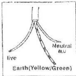
The brown live wire (connected to the "L" terminal of the terminal board) must always be connected to the live wire of the power supply mains.
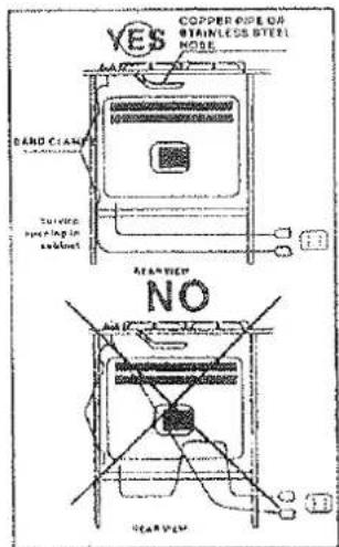
In all cases, the power supply lead must be positioned so that it does not reach a temperature 50^ C above the room temperature in any point.
One example of an ideal route is shown in the illustration. The cable is guided by means of band clamps fixed to the side of the cabinet, in order to avoid any contact with the appliance underneath the hob.
Replacing the power supply lead
If the lead has to be replaced, only HO5RR-F or HO5RN-F type cables suitable for the load and the operating temperature must be used. In addition, the yellow/green earth wire must be about 2 cm longer than the live and neutral wires.
Adapting to the different types of gas
Changing the nozzles
1) Remove the pan standee.
2) Remove the burner caps and flame caps from the burners.
3) Use a size 7 socket wrench to unscrew and remove the nozzles, replacing them with those corresponding to the type of gas to be used (see the table).
4) Reassemble the parts, reversing the operations described above.
5) Then replace the setting data (close to the mains gas connection) with the one for the new type of gas. If the pressure of the gas used is different from that specified (or variable), a suitable piped gas pressure regulator complying with the standard must be installed on the supply pipeline.

natural_image
Simple line drawing of a hand pressing down on a circular object with a handle (no text or symbols)Setting the minimum level
1) Light the burner as already described.
2) Turn the tap to the minimum flame position.
3) Remove the control knobs.
4) Use a thin straight screwdriver to turn the by-pass pin located next to the tap rod (see fig. B). For LPG, turn the by-pass pin fully clockwise.
The result should be a small, homogeneous flame which is uniform around the entire burner ring. For the dual Triple Flame version see fig. A. by-pass 1 central burner, by-pass 2 both burners.
5) Finally, check that the burner does not go out when the tap is turned quickly from the maximum to the minimum position.

A

natural_image
Simple line drawing of a mechanical setup with a central rod and base, no text or symbols present.B
Building into fitted kitchen units
natural_image
Line drawing of a gas stove with four panes and three side fans (no text or symbols)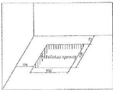
These hobs are designed for installation in fitted kitchen units up to 600mm deep with suitable characteristics.
Any cabinet side panels taller than the height of the hob itself must be at least 150mm away from the opening into which the hob is inserted.
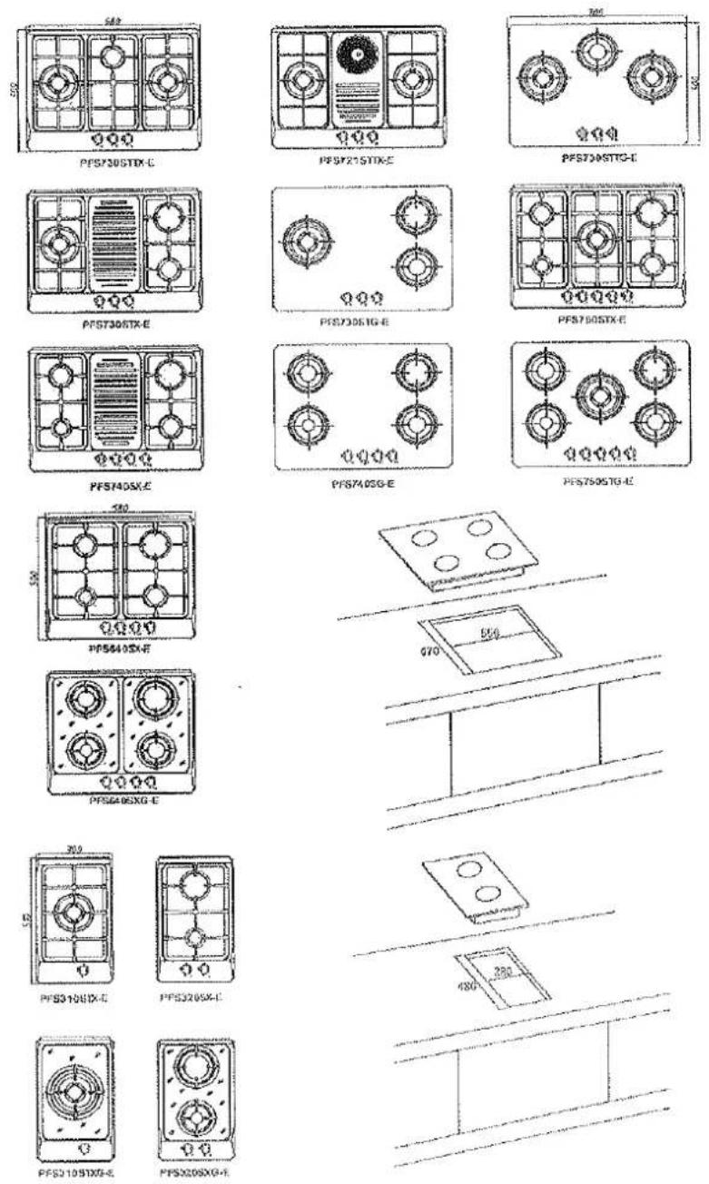
The dimensions of the hob and the installation opening are shown in the illustration.
Insertion and fixing
Before inserting the hob in the installation opening. Place the special gasket around the bottom edge of the hob.
It is important to fix this gasket evenly, without gaps or overlapping, to prevent liquid from seeping under meath the hob.
1) Remove the pan stands and the burner caps and turn the hob upside down, taking care not to damage the ignition plugs and the thermocouples.
2) Place the gasket around the bottom edge of the hob as shown in the illustration on the right.
3) Place the hob in the installation opening and push it down so that the hob is resting firmly on the cabinet, as show in the illustration. The side springs will hold it in place.

natural_image
Line drawing of hands holding a flexible tube or clip, no text or symbols present
Installation options
On base cabinet with door
When constructing the cabinet, suitable precautions must be take to prevent contact with the casing of the hob, which becomes very hot during operation. The recommended method for overcoming this problem is illustrated in fig.1
The panel underneath the hob must be easily removable to allow the hob to be lacked in position and released incase of servicing work
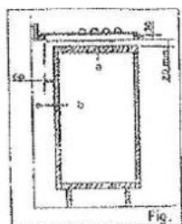
a Removable panel b Space for connections
On base cabinet with oven
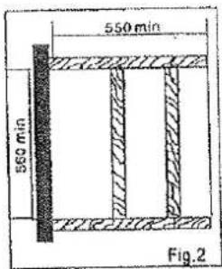
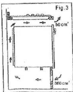
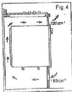
The installation compartment must have the dimensions shown in figures 2 and 3 and must have supports to allow satisfactory ventilation. Two possible methods for avoiding overheating are illustrated in figures 3 and 4. The electrical connections of the hob and oven must be made separately both for electrical reasons and to simplify removal of the oven through the front of the cabinet.
Wall cabinets or extractor hoods must be at least 650 mm above the hob.


PFS910SIX-B
PFS930STG-E
FFS936STXG-E
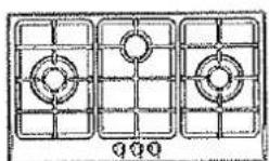
TPS930SITX-E

PFS930STTG-E
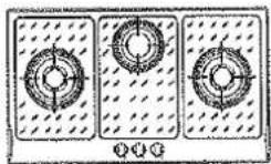
PFS930SYXG-E
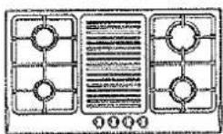
PFS940SX-B
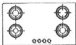
PF5940SC-T

PF59405XX-8
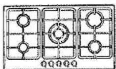
PFS910STX-E

178950STG-F
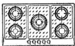
PFS950STXC-E
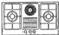
FF\$921STTX-E



natural_image
Pure technical diagram of three symmetrical mechanical components with no text or symbolsPFL050STX-E

PF1.940STX-E
PFL030STX-E

natural_image
Pure technical diagram with circular and diamond-shaped features, no text or symbols presentPFL950STG-E

PFL94057G4E
191830STGE

PFL941STX-E

natural_image
Simple line drawing of a rectangular object above a table with a circular element and a small number 24, no text or symbols present.


- Gas Built in Hob
- For Your Safety
- Installation
- During use
- Children's safety
- Cleaning and maintenance
- Service and parts
- Environmental protection advice
- Decommissioned appliances
- Contents
- For the User
- For The Installation Technician
- Guide to reading the instructions
- Description of the hob
- Instructions for use
- The hob control knobs
- Dual triple flame version
- Lighting the burners
- For correct use of the hob
- General cleaning
- Hob
- Ignition plug
- Routine maintenance
- Warranty conditions
- Instructions for the installation technician
- Installation premises
- Discharge of flue gases
- Connection to the gas supply
- Connection
- Electrical connection
- Replacing the power supply lead
- Adapting to the different types of gas
- Changing the nozzles
- Setting the minimum level
- Building into fitted kitchen units
- Insertion and fixing
- Installation options
- On base cabinet with door
- On base cabinet with oven
Brand : KELVINATOR
Model : KHGG700
Category : Cooker