
TM-2655 - Sphygmomanometer A&D Médical - Free user manual and instructions
Find the device manual for free TM-2655 A&D Médical in PDF.


| Type de produit | Automatic wrist blood pressure monitor |
| Modèle | TM-2655 |
| Marque | A&D Medical |
| Méthode de mesure | Oscillometric |
| Plage de mesure - pression | 0 to 280 mmHg |
| Plage de mesure - pouls | 30 to 180 beats/min |
| Précision - pression | ±3 mmHg |
| Précision - pouls | ±5% |
| Alimentation | 2 AAA batteries (1.5V) |
| Autonomie des piles | Approximately 300 measurements |
| Mémoire | 60 readings per user (2 users) plus date/time |
| Indicateur d'arythmie | IHB (Irregular Heartbeat) indicator |
| Détection de mouvement | Body movement detection |
| Affichage | LCD digital with large digits |
| Classification de la pression | WHO indicator (color-coded) |
| Tour de poignet compatible | 13.5 to 21.5 cm |
| Dimensions du boîtier | 72 × 72 × 28 mm |
| Poids (sans piles) | Approximately 100 g |
| Matériau du brassard | Soft fabric, latex-free |
| Arrêt automatique | After 3 minutes of inactivity |
| Entretien et nettoyage | Wipe with a dry soft cloth; do not immerse in water |
| Sécurité | CE marked, FDA registered, compliant with AAMI/ESH/ISO standards |
| Pièces détachées / réparabilité | Batteries only; no user-serviceable parts. Contact A&D Medical for service. |
| Informations générales | Designed for home use; not for continuous monitoring during medical emergencies. |
Frequently Asked Questions - TM-2655 A&D Médical
User questions about TM-2655 A&D Médical
0 question about this device. Answer the ones you know or ask your own.
Ask a new question about this device
Download the instructions for your Sphygmomanometer in PDF format for free! Find your manual TM-2655 - A&D Médical and take your electronic device back in hand. On this page are published all the documents necessary for the use of your device. TM-2655 by A&D Médical.
USER MANUAL TM-2655 A&D Médical
© 2001 A&D Company Ltd. All rights reserved.
No part of this publication may be reproduced, transmitted, transcribed, or translated into any language in any form by any means without the written permission of A&D Company Ltd.
The contents of this manual and the specifications of the instrument covered by this manual are subject to change for improvement without notice.
WARNING DEFINITIONS
The warnings described in this manual have the following meanings:

WARNING
Important information to alert you to a situation that might cause injury and/or damage to your property if instructions are not followed.

CAUTION
Important information to alert you to a situation that might cause minor injury and/or damage to your property if instructions are not followed.
Note
Important information that helps users operate the device.
COMPLIANCE
Compliance with the European Directive 93/42/EEC for Medical Products
This device conforms to the following requirements: European Directive 93/42/EEC for Medical Products act; Medical Products Act; European Standards for Electrical Equipment EN 60601-1 (General Safety Provisions), EN 60601-1-2 and EN 55011 (Electromagnetic Compatibility); European Standards pertaining to Non Invasive Blood Pressure Instruments EN 1060-1 (General Requirements), EN 1060-3 (Supplementary Requirements for Electromechanical Blood Pressure Measuring Systems).
This is evidenced by the CE mark of conformity accompanied by the reference number of a designated authority.
This device was designed for use by adults only.
Compliance with the Australian EMC Frame Work
This device conforms to the following requirements: EMC Emission Standard for Industrial, Scientific and Medical Equipment AS/NZS 2064-1997, EMC Generic Immunity standard AS/NZS 4252.1-1994. This is evidenced by the C-Tick label.
Environment for use
The device is for use in offices, sports facilities, and hospitals (waiting rooms), etc.
NOTE
This device does not have the function of automatic cycling measurement.
Therefore, a part of this device does not conform to IEC60601-2-30.
SAFETY PRECAUTIONS

WARNING
Grounding
To avoid electrical shock, connect the power cable to a medical electrical outlet having a ground terminal for grounding the device.
Fuse
To avoid a fire hazard, use only a fuse of the proper type, voltage and current rating as specified on the rear panel. Never bypass a fuse by shorting across the fuse holder and connectors.
Service
Internal service or adjustment to this device should be performed by a qualified person only. Do not disassemble or modify the device
Device failure
If a device failure occurs, promptly stop using it. Remove the device from the patient and secure the patient's safety. Turn the power off and disconnect the power cable from the electrical outlet. Affix a notice such as "Out of Order" and "Do Not Use" on the device. Ask the nearest dealer for services
To interpret blood pressure measurements
Only a trained medical professional is qualified to interpret the blood pressure measurements. No device can replace regular medical checkups by a doctor. A doctor should verify the blood pressure measurements before making adjustments to medication.
When the device gets wet because of a liquid spill
If the device gets wet, promptly stop using it. Remove the device from the patient and secure the patient's safety. Turn the power off and disconnect the power cable from the electrical outlet. Affix a notice such as "Out of Order" and "Do Not Use" on the device. Ask the nearest dealer for service.

CAUTION
In case of emergency
Press the EMERGENCY STOP switch located on the front of the device. This will release the air in the arm cuff so that the arm can be removed easily. It also operates if there is a power failure.
To stop the operation at any time
Press the START/STOP switch located on the display panel. The quick exhaust will release the air in the arm cuff and the arm cuff will become loose.
Maintenance/Inspection
Check all functions periodically. Ask the nearest dealer for this inspection.
Do not disassemble or modify the device.
If the device is used for the first time after an extended period of storage, check the device for proper operation.
GENERAL PRECAUTIONS
Obey the following precautions for safe and correct usage.
Precautions unique to the TM-2655/TM-2655P appear on the relevant page in this manual. Read the manual thoroughly before use.
When installing and storing the device
■ Install or store the device away from moisture.
■ Do not install or store the device where the device may be badly affected by extreme temperature, humidity, direct sunlight, draft, dust, salinity or sulfur content in the air.
■ Do not install or store the device where chemicals, and corrosive or explosive gases are stored or present.
■ Install or store the device in a secure, level and stable location.
■ Install or store the device where adequate power is provided. (Where a medical 3P electrical outlet is provided.)
Before use
- Check to make sure the device operates safely and accurately.
■ Check all cables for proper connection.
■ When other medical equipment is used at the same time, a diagnostic error or dangerous situation may occur. Check all connections to make sure they do not interfere with each other.
■ When other telemeters are used, check that mutual interference will not cause a problem.
During use
■ Check the patient and the device during use.
■ If medical or operational problems are found in the device or the patient, stop using the device immediately, check the status of the patient and take proper action.
■ Do not use the device during MRI scanning.
■ Do not use the device on a patient using a heart-lung machine.
■ High frequency interference by electrosurgery or energy discharged by a defibrillator may damage the device. Follow the precautions described in the manual for each device.
- Do not use a cellular telephone near the device. It could affect the device's operation.
■ The personal computer and medical equipment connected to the device are not allowed to be in the patient area.
■ The personal computer used must conform to IEC60950
After use
■ Follow the predetermined procedure to return the operation switches to their original positions, and then turn off the power.
■ Do not forcibly pull out the cables. Hold the connector with your hand when disconnecting the cable.
- Keep the device clean and in proper operating condition so that it can be used without problem during the next operation.
■ Clean the accessories and arrange them before storage.
Environmental protection
■ Remove the built-in lithium battery from the device when the device is to be disposed of.
This device, any part of, and the built-in lithium battery are not treated as ordinary household waste, and must be disposed of according to the applicable regulations.
CONTENTS
WARNING DEFINITIONS...... I
COMPLIANCE......II
SAFETY PRECAUTIONS......III
GENERAL PRECAUTIONS IV
1. INTRODUCTION .... 3
1-1 Features....3
1-2 Unpacking and Inspection ....4
1-3 Specifications....5
2. PART NAMES 6
2-1 Main Unit....6
2-2 Rear Panel....7
2-3 Symbols....7
3. INSTALLATION 8
4. OPERATION....9
5. SETTING THE CLOCK 11
5-1 Clock Adjustment Mode....11
5-2 A Setting Example....11
6. INSTALLING THE PRINTER PAPER.... 13
7. SETTING THE FUNCTIONS ...... 14
7-1 Function Setting Mode....14
7-2 Description of the Functions....15
7-3 Printing Samples....16
8. COMMUNICATION SPECIFICATIONS....17
8-1 Channel 1 : Miniature DIN 8-pin ....17
8-2 Channel 2: D-sub 9-pin....18
9. MAINTENANCE....19
9-1 Replacing the Arm Cuff Cover 19
9-2 Replacing the Fuses 20
9-3 Checking the Counter 20
Displaying the counter.... 20
Resetting the counter 20
9-4 Error Codes 20
9-5 Maintenance 21
9-6 Cleaning....21
9-7 Options and Consumables 22
10. TROUBLESHOOTING....23
11. EXTERNAL DIMENSIONS....24
1. INTRODUCTION
1-1 Features
The TM-2655/TM-2655P is a blood pressure monitor that measures systolic and diastolic blood pressure and pulse. The TM-2655 is a standard model; the TM-2655P is equipped with a printer unit. The features of the devices are as follows:
COMPACT DESIGN
Due to its compactness, the TM-2655/TM-2655P can be installed in an area where space is limited. You can measure your blood pressure on either arm.
AUTOMATIC-CUFF SYSTEM / AUTOMATIC-EXHAUST-ADJUSTMENT SYSTEM
The arm cuff is wrapped around the arm by pressing the START/STOP switch and deflation speed is automatically controlled. No special adjustment is required. All you have to do is insert your arm into the arm insertion section to the shoulder and press the START/STOP switch. The rest is done automatically. You can easily and quickly measure your blood pressure. The TM-2655/TM-2655P is suitable for mass medical check-ups at firms and sports facilities and in hospital waiting rooms when used for a pre-check of the patient's health status.
BUILT-IN PRINTER (TM-2655P only)
The TM-2655P is equipped with a printer unit, which allows measurement results to be printed out for record keeping. The print format can be selected from results only, results with pulse pressure graph or a list of the results.
BUILT-IN CLOCK
The date and time of measurement can be printed along with the measurement results.
COUNTER (UP TO 999999 COUNTS)
The counter indicates how often the device is used. It can be a helpful guideline for maintaining the device.
SAFETY SYSTEM
The TM-2655/TM-2655P adopts an emergency stop system. In case of emergency, pressing the EMERGENCY STOP switch will release the air in the arm cuff so that the arm can be removed easily. This system also functions if there is a power failure.
REPLACEABLE ARM CUFF COVER
The arm cuff cover can be easily replaced.
1-2 Unpacking and Inspection

CAUTION
Handle this device carefully at all times. Strong shock to the device may cause trouble during operation.
Note
Save the packing material for later use.
Unpack the TM-2655/TM-2655P carefully and verify that the following items are contained.

TM-2655/TM-2655P

Arm cuff cover (2 pcs)
With one factory-installed

Fig.1 Items contained
Printer paper (2 rolls)

Instruction manual
Table 1 Specifications
Performance specifications
| General | |
| Power supply 120VAC 60 Hz (For USA area) | 230VAC 50 Hz (For Europe area)(factory-preset) |
| Power consumption Approx. 40VA | |
| Protection against electrical shock | Class I, Type B |
| Display | LED |
| EMC | EN 60601-1-2 |
| Blood pressure measurement | |
| Blood pressure measuring method Oscillometric method | |
| Pressure detection method Capacitance type pressure transducer | |
| Pressure range 0 – 300 mmHg | |
| Accuracy | Pressure: ±3 mmHgPulse rate: ±5% |
| Measurement range Blood pressure: 10 – 280 mmHgPulse rate: 30 – 200 bpm | |
| Pressurizing method Micro pump | |
| Air pressure control method Rubber valve, ceramic valve | |
| Rapid air exhaust system Electromagnetic valve | |
| Safety mechanism | The electromagnetic valve is released when approx. 320 mmHg or greater is detected. |
| Communications functions | Serial output: RS232C level |
Environment specifications
| Operating temperature and humidity | 10 to 40°C, 85%RH or less, non condensing |
| Storage temperature and humidity | -20 to 60°C, 95%RH or less, non condensing |
Physical specifications
| Overall dimensions | 245(W) X 320(H) X 390(D) mm |
| Weight | Approx. 9 kg |
2. PART NAMES
2-1 Main Unit

Fig.2 TM-2655/TM-2655P whole view
Note
● The printer unit is available only for the TM-2655P.
- The human sensor area appears the same for both models, but it functions only for the TM-2655P.
● The illustration above is not to scale.
2-2 Rear Panel

2-3 Symbols
The symbols used with the TM-2655/TM-2655P have the following functions or meanings.
Table 2 Symbol descriptions
| Symbols | Function/Meaning | |
 | Starts and stops a measurement. | |
 | Turns the device on. | |
 | Turns the device off. | |
 | Alternating current | |
 | Serial number | |
 | Fuse | |
 | RS-232C | |
| [2HK6] | Date of manufacturer | |
 | Type B: Device, cuff and tubing are designed to provide special protection against electrical shocks. | |
 | The medical device label by the EC directive | |
 | The certification trade mark registered to the Australian Communications Authority by the Trademarks office. | |
 | Systolic blood pressure in mmHg | |
 | ||
| [2ZWG] | Diastolic blood pressure in mmHg | |
 | ||
| [X3TG] | Pulse beats per minute | |
 | ||
 | See the instruction manual. | |
3. INSTALLATION
Follow the procedure below to install the TM-2655/TM-2655P.
- To ensure that the TM-2655/TM-2655P works properly, install the device in an environment where:
■ The temperature range is from 10° C to 40° C ( 50° F to 104° F).
■ The humidity is less than 85% (non condensing).
■ It is away from water, dust, chemicals, and corrosive or explosive gases.
■ It is not exposed to direct sunlight.
-
Place the TM-2655/TM-2655P on a table solid enough to support its weight.
-
Adjust the height of the chair and table so that the arm insertion section is at the user's heart level.

Fig.4 Proper installation
- Use the power cable provided with the device to connect between the AC INPUT connector and an electrical outlet.
Using the anti-theft opening, secure the device to the table with a solid chain.

Fig.5 Power cable connection
Note
Be sure to use the correct voltage for the power source.
4. OPERATION
- Turn on the POWER switch located on the rear panel.
When the POWER switch is turned on, all of the display symbols will appear for several seconds. Then;
■ (TM-2655) "0" (zero) appears in the SYSTOLIC pressure display, indicating that the device is ready for measurement.
■ (TM-2655P) The human sensor functions for three minutes. When it does not detect a person, “.” (dot) appears in the SYSTOLIC pressure display, indicating that the device is ready for measurement.
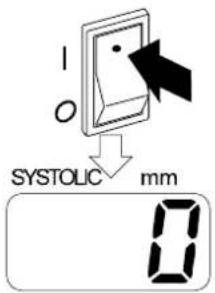
Fig.6 POWER switch and SYSTOLIC display (TM-2566)
- Take off your jacket.
If you wear a thick jacket, take it off for a better measurement.
Note
Wearing a thick jacket may cause a faint pulse, and result in a measurement error.
- Adjust the height of the chair and table.
Adjust the height of the chair and table so that the arm insertion section is at your heart level.
- Insert your arm into the arm insertion section.
Note
Be sure to insert your arm to the shoulder.
-
Press the START/STOP switch to start measurement.
-
The cuff will be pressurized automatically up to the predetermined pressure. Refer to "7-2 Description of the Functions" for details.
-
When pressurization is complete, the automatic exhaust mechanism will gradually reduce the pressure in the cuff. Just relax and remain still.

Fig.7 Proper posture


Fig.8 Measuring procedure
- When the measurement is complete, the air is automatically released from the cuff and the cuff will become loose.
- The measurement results appear in the display.
- (TM-2655P) The measurement results are output to the printer.

Fig.9 Measurement results
Note
- To stop the measurement at any time, press the START/STOP switch. The quick exhaust will reduce the pressure in the cuff and the cuff will become loose.
- If the air is not exhausted even when the START/STOP switch is pressed, press the EMERGENCY STOP switch.
- If your arm can not be removed from the cuff due to the power failure, press the safety lever located on the front lower part of the device. It disconnects the clutch to loosen the cuff.
- Please wait for about 10 minutes before repeating the measurement.
5. SETTING THE CLOCK
5-1 Clock Adjustment Mode
The clock is set in the clock adjustment mode. The clock adjustment mode display and switches used are as shown below:
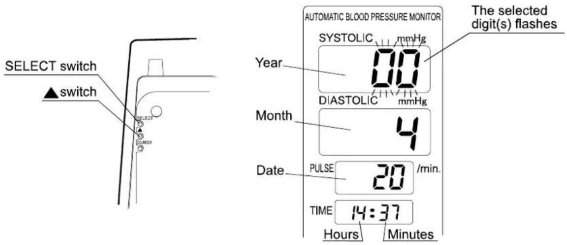
Fig.10 Switches for setting the clock and the clock adjustment mode display
Table 3 Switches for setting the clock
| SELECT switch (1) | Press to enter the clock adjustment mode.(2) (In the clock adjustment mode) Press to select the unit to be adjusted. The selected unit flashes. Each time the switch is pressed, the flashing unit changes: from “Year” to “Month”, “Date”, “Hours”, and “Minutes”. (3) Press to quit the clock adjustment mode. |
| ▲ switch Press | to change the flashing digit(s). |
5-2 A Setting Example
The following is the procedure to adjust the clock to 14:07, April 20, 2001.
- Press the SELECT switch to make the SYSTOLIC display flash.
- Press the ▲ switch to display "01" for 2001.
- Press the SELECT switch to make the DIASTOLIC display flash.
- Press the ▲ switch to display "4" for April.
- Press the SELECT switch to make the PULSE display flash.
- Press the ▲ switch to display "20".
-
Press the SELECT switch to make the hours section of the TIME display flash.
-
Press the ▲ switch to display "14".
-
Press the SELECT switch to make the minutes section of the TIME display flash.
-
Press the ▲ switch to display "07".
-
Press the SELECT switch to return to the measurement mode.
Note
- If no operation is performed for one minute, while setting the minutes section and for five seconds while setting the others, the settings performed so far will be confirmed and the device will return to the measurement mode.
● The clock can be set up to December 31, 2091.
6. INSTALLING THE PRINTER PAPER
(This chapter is applicable only to the TM-2655P.)
With the power turned on, install the printer paper as follows:
- Cut the top end of the printer paper with scissors. If the end is not smooth, it may cause a paper jam or damage the printer head.
- Press lightly on the center of the printer cover to open the cover.
- Raise the lever located on the right side of the printer. Insert the printer paper into the paper feed slot as shown. The paper is fed automatically.
- Press the PAPER FEED switch to feed the paper by 10 cm. Confirm that the paper is fed straight. If not, re-install the paper because it may cause a paper jam.
- Lower the lever and feed the paper. The paper will be cut automatically.
- Close the cover. Press lightly on the center of the printer cover to secure it in position.
Note
- With high-speed printing, about 700 printings can be performed. With three-line printing, about 600 printings.
- Replace the printer paper when the red end is reached.
- Use the specified thermal paper, which is sold separately.
![graph TD A["Printer cover"] --> B["Printer head"] B --> C["Paper feed slot"] C --> D["Lever"] D --> E["PAPER FEED switch"] E --> F["138 82 75 456"]](/content/2026/05/959383/images/cf2f1ee15a0363213528247ed39ebb4553e39bfdd7ab1592af608cb94dcb458b.jpg)
Fig.11 Paper installation procedure
7. SETTING THE FUNCTIONS
7-1 Function Setting Mode
The TM-2655/TM-2655P is provided with various functions, which allow the user to set the device to suit the user's requirements. The functions are set in the function setting mode. The function setting mode display and switches used are as shown below:

Fig.12 Switches for setting the function and the function setting mode display
Table 4 Switches for setting the functions
| ▲ switch and SELECT switch | Hold down th▲ switch and press the SELECT switch to enter the function setting mode. |
| COUNTER switch Press to select | the function to set. |
| ▲ switch Press to select the function parameter. | |
- Hold down the ▲ switch and press the SELECT switch. "f01" appears in the SYSTOLIC pressure display. This indicates that the monitor is now in the function setting mode.
- Press the COUNTER switch to select the function number to set. Each time the switch is pressed, the function number changes: from "f01" to "f02" to "f03".
3 Press the ▲ switch to select the function parameter. - When the settings are complete, turn the power off and turn it on again. The settings are saved.
7-2 Description of the Functions
Table 5 Functions
| No. | Function | SYSTOLIC display | DIASTOLIC display | Description |
| F01 | —— | f01 | off | Not available. |
| F02 | Printer setting(See “7-3 Printing Samples” for what each method printing looks like.)TM-2655P only | f02 | off No printing | |
| 1 High-speed printing | ||||
| 2 3-line printing | ||||
| 3 3-line printing | ||||
| 4 Graph printing | ||||
| 5 Table printing | ||||
| F03 | f03 | off No bit pattern printing | ||
| on Bit pattern printing | ||||
| F04 | Displaying time | f04 | 999 The results remain in the display unless another operation is performed. | |
| 5 Displays the results for 5 seconds. | ||||
| 10 Displays the results for 10 seconds. | ||||
| 20 Displays the results for 20 seconds. | ||||
| F05 | External connection | Ff05 | 1 Terminals 1 and 2 to a PC | |
| 2 Terminal 1 to a PC Terminal 2 to a card reader | ||||
| 3 Terminal 1 to a scale Terminal 2 to a PC | ||||
| F06 | Pressurization | Ff06 | au Automatic pressurization | |
| 160 Pressurizes the cuff up to 160 mmHg. | ||||
| 180 Pressurizes the cuff up to 180 mmHg. | ||||
| 200 Pressurizes the cuff up to 200 mmHg. | ||||
| F07 | Channel 1 rate | baud Ff07 | 120 1200 bps | |
| 240 2400 bps | ||||
| 480 4800 bps | ||||
| 960 9600 bps | ||||
| F08 | Channel 2 rate | baud Ff08 | 120 1200 bps | |
| 240 2400 bps | ||||
| 480 4800 bps | ||||
| 960 9600 bps | ||||
| F09 | —— | Ff09 | H9 | Not available. |
| F10 | Human sensor | Ff10 | off Does not detect a human presence. | |
| on Detects a human presence. | ||||
| F11 | Automatic external output | Ff11 | off Does not output the results automatically. | |
| on Outputs the results automatically. | ||||
High-speed printing
![May 26 2000 11:41 SYS DIA PUL 110 75 60 [mmHg] [bpm]](/content/2026/05/959383/images/8c83d5ba1c4e6613bfaea005cbbef468c84683c43765b462fe12bc00511743ee.jpg)
Graph printing

3-line printing


Table printing
![May 26 2000 11:46 [mmHg] [bpm] No. TIME SYS DIA PUL 00001 13:25 109 74 60 00002 13:26 111 75 60 00003 13:27 113 75 59 00004 13:28 113 76 59 00005 13:29 110 76 60 00006 13:30 110 76 59](/content/2026/05/959383/images/2c0e6b088b29b2daadc77fae8f326fe50329674a5bfae386b9710b2cdbe23ce5.jpg)
Bit pattern printing
![May 26 2000 11:41 SYS DIA PUL 110 75 60 [mmHg] [bpm] AND A&D Company Limited](/content/2026/05/959383/images/52c0034d4f0cfaf7a133f6216fe004ab7dcda97b164164a059838233d0e63a9d.jpg)
Fig.13 Printing samples
Note
Bit pattern printing is available only for the TM-2655P. With this format, some items such as the company name can be printed. For details, contact your nearest dealer.
8. COMMUNICATION SPECIFICATIONS
The TM-2655/TM-2655P is equipped with two RS-232C channels. Various settings for each channel are available in the function setting mode. Refer to "7-2 Description of the Functions" for details.
8-1 Channel 1 : Miniature DIN 8-pin

CAUTION
- The personal computer and medical equipment connected to the device are not allowed to be in the patient area.
● The personal computer used must conform to IEC60950
Specifications
Table 6 Channel 1 specifications
| Standard Conforms to EIA RS-232C | |
| Transmission | Asynchronous, half-duplex |
| Baud rate 1200 | 2400, 4800, 9600 bps (Can be changed in the function setting mode “F07”.) |
| Data bits 8 bits | |
| Parity bit None | |
| Stop bits 1 bit | |
| Code | ASCII |
Equipment available for connection
Channel 1: Scales, and automatic weight and height scales manufactured by A&D
Channel 2: Personal computer
Pin assignment

| Pin No. | Signal name | Description |
| 1 | TXD | Send |
| 2 | RXD | Receive data |
| 3 | RTS Ready to send | |
| 4 | - | Not connected |
| 5 | CTS Clear to send | |
| 6 | GND | Signal ground |
| 7 | - | Not connected |
| 8 | - | Not connected |
data
Note
Do not use pins 4, 7, and 8.
They are used by the device.
Fig.14 Pin assignment
Cable connection between the device and a personal computer
TM-2655/TM-2655P
Personal computer
Mini DIN connector
D-sub connector

Fig.15 Cable connection diagram
8-2 Channel 2: D-sub 9-pin

CAUTION
- The personal computer and medical equipment connected to the device are not allowed to be in the patient area.
● The personal computer used must conform to IEC60950
Specifications
Table 7 Channel 2 specifications
| Standard Conforms to EIA RS-232C | |
| Transmission | Asynchronous, half-duplex |
| Baud rate 1200 | 0, 2400, 4800, 9600 bps (Can be changed in the function setting mode “F08”.) |
| Data bits 8 bits | |
| Parity bit None | |
| Stop bits 1 bit | |
| Code | ASCII |
Equipment available for connection
Channel 1: Personal computer
Channel 2: Card reader
Pin assignment

| Pin No. | Signal name D | rection Description | |
| 1 | - | - - | |
| 2 | RXD | In Receive data | |
| 3 | TXD | Out | Send data |
| 4 | DTR | Out | Data terminal ready |
| 5 | GND | - Signal ground | |
| 6 | DSR | In | Data set ready |
| 7 | RTS | Out | Ready to send |
| 8 | CTS | In | Clear to send |
| 9 | - | - - | |
Note
The protocol depends on the equipment connected.
Fig.16 Pin assignment
Cable connection between the device and a personal computer
TM-2655/TM-2655P
Personal computer
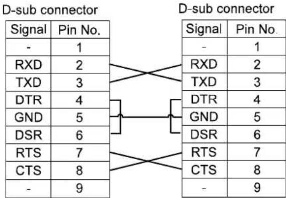
Fig.17 Cable connection diagram
9. MAINTENANCE
9-1 Replacing the Arm Cuff Cover
Replace the arm cuff cover as follows:
- Locate the cover at the bottom of the arm insertion section. Slide the cover downward to open it. The screw is exposed.
Using the screwdriver, loosen the screw and remove the front frame.
-
Remove the four screws on the rear panel to remove the armrest and the rear panel.
-
Remove the front vinyl ring of the arm cuff cover from the groove. Remove the rear vinyl ring of the arm cuff cover from the groove. Pull out the arm cuff cover.
-
Place a new arm cuff cover in the arm cuff. Secure the front and rear vinyl rings of the arm cuff cover in the groove. Smooth the cover cloth near the grooves.
-
Replace the rear panel, the armrest, and the front frame in the reversed order of removal. Slide the cover upward to secure it in position.
Note
The arm cuff cover is a consumable. Purchase it separately.


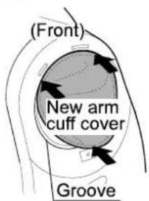
Fig.18 Arm cuff replacing procedu
9-2 Replacing the Fuses
Replace the fuses as follows:
- Remove the caps of both fuse holders located on the rear panel.
- Replace both fuses with new ones.
- Re-install the fuse holder caps.

Fig.19 Fuse holders
Note
Use only fuses of the proper type, voltage and current rating as specified on the rear panel, and that conform to IEC60127.
9-3 Checking the Counter
The TM-2655/TM-2655P is equipped with a counter function, which indicates how many times the device has measured blood pressure. The counter data remains in memory even after the power is turned off. Use the counter function to check the frequency of the device use or as the guideline for a periodic cleaning
Displaying the counter
Press the COUNTER switch. The counter data appears in the SYSTOLIC and DIASTOLIC displays for about 4 seconds.
Note
Do not keep the COUNTER switch pressed. It will reset the counter data to zero.
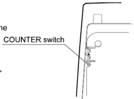
Fig.20 COUNTER switch
Resetting the counter
Hold down the COUNTER switch for 4 seconds or more. The counter data will be reset to zero.
9-4 Error Codes
Table 9 Error codes
| Error code | Description |
| pe | The printer paper has run out. Install a new roll of printer paper. |
| HU | The printer head is up. Lower the lever and lock the printer paper in position. |
| err | A measurement error has occurred. Refer to “10. Troubleshooting”. |
9-5 Maintenance
Do not open the device. It uses delicate electronic components and an intricate air unit that could be damaged. If you can not fix the problem using the troubleshooting instructions, request service from your supplier or from the A&D service group. The A&D service group will provide technical information, spare parts and units to authorized suppliers.
The technical testing procedures, which should be done at least every two years, can be performed either by the manufacturer or by an authorized repair service in accordance with the regulations governing manufacturing of medical products.
9-6 Cleaning

CAUTION
- Never immerse the TM-2655/TM-2655P in water for cleaning, that may damage the electronic parts inside.
- Never use thinner or a strong detergent for cleaning, that may discolor or deform the plastic case and display panel.
Housing case
Clean the case gently using a soft cloth moistened with water and mild detergent or alcohol.
Display panel
Clean the display gently so as not to scratch the panel surface. Use a soft cloth moistened with water.
Arm cuff cover
When the arm cuff cover becomes dirty or it is worn out, replace with a new one. Refer to "9-1 Replacing the Arm Cuff Cover".
Note
If the cover is not installed properly, it may cause problems in operation.
9-7 Options and Consumables
Options and consumables available for the TM-2655/TM-2655P are shown below. Order them from the nearest dealer. Use the part numbers when ordering.
- Table TM-9325
- Standard stool · TM-9312 · · · · · · · · · · · · ·
● Chair (Gas shock suspension) TM-9315A
● Printer paper (5 rolls) AX-PP147-S
● Arm cuff cover AX-133003442-S
● Power cable (cord set) KO:243 (for 230VAC)
● Power cable (cord set) KO:242 (for 240VAC)
10. TROUBLESHOOTING
If the TM-2655/TM-2655P does not function properly or an error code appears, try the following corrective actions.
Table 10 Troubleshooting
| Problem Check | this Corrective action | |
| Nothing appears in the display, even when the power is turned on. | Is the power cable connected properly? | Connect the power cable properly. |
| Has a fuse burned out? | Replace both fuses with new ones. (Size 5x20mm. Rated voltage and current are specified on the rear panel). | |
| The cuff will not inflate. | Is the arm cuff cover installed with high tension (too tight)? | Refer to “9-1 Replacing the Arm Cuff Cover” to re-install the cover. |
| The device will not measure. (Eerr appears.) | Is your posture proper? | Place your arm at your heart level, relax and remain still during the measurement. |
| Do you remain still? | Do not move your arm during the measurement. Relax and remain still. | |
| —— | Wearing a thick jacket may cause a faint pulse, and result in a measurement error. Take off the jacket. | |
| —— | This device bases its measurements on the heartbeat. If you have a very weak or irregular heartbeat, the device may have difficulty determining your blood pressure. | |
| The printer does not print. | Is the printer paper installed? (pe appears.) | Refer to “6. INSTALLING THE PRINTER PAPER” to install the printer paper. |
| Is the printer head up? (HU appears.) | Lower the lever and lock the printer paper in position | |
| Is the printer paper inserted straight or is the printer paper jammed? | Refer to “6. INSTALLING THE PRINTER PAPER” to re-install the printer paper. | |
| Is the printer setting correct? | Refer to “7-2 Description of the Functions” to select the correct printer setting. |
Note
If the actions described above do not solve the problem, contact the dealer. Do not attempt to repair the device yourself.
11. EXTERNAL DIMENSIONS


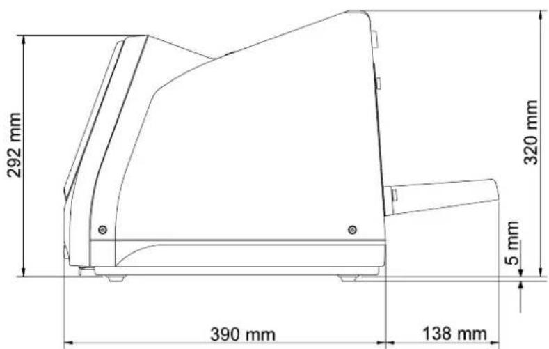
Fig.20 External dimensions
Note
The illustration above indicates the TM-2655P with the printer unit. The dimensions are the same for the TM-2655 and TM-2655P.

- © 2001 A&D COMPANY LTD. ALL RIGHTS RESERVED
- WARNING DEFINITIONS
- WARNING
- CAUTION
- NOTE
- COMPLIANCE
- COMPLIANCE WITH THE EUROPEAN DIRECTIVE 93/42/EEC FOR MEDICAL PRODUCTS
- COMPLIANCE WITH THE AUSTRALIAN EMC FRAME WORK
- ENVIRONMENT FOR USE
- SAFETY PRECAUTIONS
- GROUNDING
- FUSE
- SERVICE
- DEVICE FAILURE
- TO INTERPRET BLOOD PRESSURE MEASUREMENTS
- WHEN THE DEVICE GETS WET BECAUSE OF A LIQUID SPILL
- IN CASE OF EMERGENCY
- TO STOP THE OPERATION AT ANY TIME
- MAINTENANCE/INSPECTION
- GENERAL PRECAUTIONS
- WHEN INSTALLING AND STORING THE DEVICE
- BEFORE USE
- DURING USE
- AFTER USE
- ENVIRONMENTAL PROTECTION
- CONTENTS
- WARNING DEFINITIONS...... I
- COMPLIANCE......II
- SAFETY PRECAUTIONS......III
- GENERAL PRECAUTIONS IV
- INTRODUCTION .... 3
- PART NAMES 6
- INSTALLATION 8
- OPERATION....9
- SETTING THE CLOCK 11
- INSTALLING THE PRINTER PAPER.... 13
- SETTING THE FUNCTIONS ...... 14
- COMMUNICATION SPECIFICATIONS....17
- MAINTENANCE....19
- TROUBLESHOOTING....23
- EXTERNAL DIMENSIONS....24
- INTRODUCTION
- FEATURES
- COMPACT DESIGN
- AUTOMATIC-CUFF SYSTEM / AUTOMATIC-EXHAUST-ADJUSTMENT SYSTEM
- BUILT-IN PRINTER (TM-2655P ONLY)
- BUILT-IN CLOCK
- COUNTER (UP TO 999999 COUNTS)
- SAFETY SYSTEM
- REPLACEABLE ARM CUFF COVER
- UNPACKING AND INSPECTION
- PART NAMES
- MAIN UNIT
- REAR PANEL
- SYMBOLS
- INSTALLATION
- OPERATION
- SETTING THE CLOCK
- CLOCK ADJUSTMENT MODE
- 5-2 A SETTING EXAMPLE
- INSTALLING THE PRINTER PAPER
- SETTING THE FUNCTIONS
- FUNCTION SETTING MODE
- DESCRIPTION OF THE FUNCTIONS
- COMMUNICATION SPECIFICATIONS
- CHANNEL 1 : MINIATURE DIN 8-PIN
- SPECIFICATIONS
- EQUIPMENT AVAILABLE FOR CONNECTION
- PIN ASSIGNMENT
- CABLE CONNECTION BETWEEN THE DEVICE AND A PERSONAL COMPUTER
- CHANNEL 2: D-SUB 9-PIN
- MAINTENANCE
- REPLACING THE ARM CUFF COVER
- REPLACING THE FUSES
- REPLACE THE FUSES AS FOLLOWS
- CHECKING THE COUNTER
- DISPLAYING THE COUNTER
- RESETTING THE COUNTER
- ERROR CODES
- CLEANING
- HOUSING CASE
- DISPLAY PANEL
- ARM CUFF COVER
- OPTIONS AND CONSUMABLES
- TROUBLESHOOTING
- EXTERNAL DIMENSIONS
Brand : A&D Médical
Model : TM-2655
Category : Sphygmomanometer