
FM1STUZ-24U - Timer INTERMATIC - Free user manual and instructions
Find the device manual for free FM1STUZ-24U INTERMATIC in PDF.


| Product Type | Time Switch (24-hour or 7-day programmable) |
| Brand | Intermatic |
| Model | FM1STUZ-24U |
| Supply Voltage (Synchronous) | 24 VAC, 120 VAC, 240 VAC, 60 Hz |
| Supply Voltage (Quartz) | 24 VAC/DC, 120 VAC, 240 VAC, 50/60 Hz |
| Switch Type | SPDT |
| Switch Rating | 21 A @ 250 VAC resistive; 1350 W tungsten; 1 HP @ 125 VAC; 2 HP @ 240 VAC |
| Ambient Temperature Range (Synchronous) | -40°F to 180°F (-40°C to 82°C) |
| Ambient Temperature Range (Quartz) | -20°F to 140°F (-29°C to 60°C) |
| Terminals | 1/4" spade terminals |
| Reserve Carryover (Quartz) | 72 hours |
| Agency Approvals | UL Recognized |
| Weight | Approximately 3 oz (85 g) |
| Dimensions (Approximate) | 2.5" x 2.5" x 1.5" (64 x 64 x 38 mm) |
| Mounting Options | Flush mount, surface mount in panel, DIN rail mount (with optional housing), indoor/outdoor enclosure available |
| Programming Type | 7-day (SW, QRW models) or 24-hour (ST, QRT models) dial with captive trippers |
| Manual Override Switch | 3-way: Auto (center), Permanent ON (I), Permanent OFF (O) |
| Applications | HVAC, lighting, refrigeration, security, pumps, spas, and other loads requiring 24-hour or 7-day scheduling |
| Color | Black (typical) |
| Operating Voltage Range (24V Quartz) | 6 VDC to 24 VDC or 24 VAC |
Frequently Asked Questions - FM1STUZ-24U INTERMATIC
User questions about FM1STUZ-24U INTERMATIC
0 question about this device. Answer the ones you know or ask your own.
Ask a new question about this device
Download the instructions for your Timer in PDF format for free! Find your manual FM1STUZ-24U - INTERMATIC and take your electronic device back in hand. On this page are published all the documents necessary for the use of your device. FM1STUZ-24U by INTERMATIC.
USER MANUAL FM1STUZ-24U INTERMATIC
Operating Instructions
FM/1 Series Time Switches

natural_image
Close-up of a black industrial rotary dial with teeth and scale markings (no readable text or symbols)TECHNICAL DATA
Supply Voltage: Synchronous: 24, 120 and 240VAC, 60Hz Quartz: 24V AC/DC, 120 and 240VAC 50/60 Hz
Switch Type: SPDT
Switch Rating: 21A @ 250VAC resistive 1350 watt tungsten 1HP @ 125VAC 2HP @ 240VAC
Ambient
Temp. Range: -40^ to 180^ , synchronous units -20^ to 140^ , quartz units
Terminals: 1/4" spade terminals
Reserve Carryover: 72 hours for quartz units
Weight: Approximately 3 oz.
Agency Approvals: UL Recognized
NOTE: 24V quartz unit will operate on 6VDC, 12VDC, or 24VDC
APPLICATIONS
The FM/1 series of time switches are designed for control of heating, ventilating, air conditioning, refrigeration, lighting, security, circulating pumps, spas or any electrical load requiring 24-hour or 7-day scheduling.
WIRING
Verify input voltage stated on back of unit. Use 1/4" quick connects and make connections in accordance with the wiring diagram shown and applicable code requirements. When using 24V units, it is important to use transformers that will supply the required 24 volts AC to terminals 1 & 2.
Terminal Connections
Contacts shown in "Off" position (trippers pushed inward) "On" position (trippers pushed outward) will close contacts 3 & 4

flowchart
graph TD
    A["5 NC"] --> B["4 NO"]
    B --> C["3 COM"]
    D["M"] --> E["2 INPUT"]
    D --> F["1 INPUT"]
MOUNTING
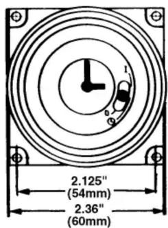
The standard FM/1 units can be flush mounted (mounting kit with screws available) or surface mounted inside a panel. A printed circuit board mounting base is also available. An indoor or outdoor enclosure is available for stand-alone mounting. In addition, unit is also available in DIN housing for flush or surface mounting (see MIL72, Digi 20 or Digi 42 data sheets). Optional clear plastic dust cover is available.
Dimensions
FM/1 synchronous/quartz

TIME SETTING
TO SET THE CURRENT TIME (AND DAY OF WEEK ON 7 DAY UNITS), TURN THE MINUTE HAND CLOCKWISE. DO NOT SET THE TIME BY ROTATING "OUTER" DIAL.
Turn the minute hand clockwise until the day of the week (7-day timer) and the time of day on the outer dial is aligned with the triangle marker on the inner dial (two o'clock position).
Example for 7-day program dial Monday 10:30 AM. Turn the minute hand clockwise until Monday 10:30 AM is aligned with the triangle on the inner dial. The hour and minute hand will show exactly 10:30.
Example for 24-hour program dial 10:30 AM. Turn the minute hand clockwise until 10:30 AM is aligned with the triangle on the inner dial. The hour and the minute dial will show exactly 10:30.
PROGRAMMING
7-Day (SW, QRW Models)
The weekly program dial reflects the seven days of the week and AM/PM imprints for each day.
The time switch is programmed by pushing the captive trippers to the outer ring position for the entire period that the load is to be turned “ON”, i.e., two hours for each tripper on the 7-Day dial. When the tripper is pushed to the inside, the switch is in the “OFF” position.
24-Hour (ST, QRT Models)
The 24-Hour dial has quarter-hour divisions and AM/PM indications.
The time switch is programmed by pushing the captive trippers to the outer ring position for the entire period that the load is to be turned “ON”, i.e., fifteen minutes for each tripper on the 24-Hour dial. When the tripper is pushed to the inside, the switch is in the “OFF” position.
PROGRAMMING WITH MANUAL OVERRIDE SWITCH
AUTOMATIC MODE
In order to operate the time switch module in the automatic mode, the manual switch must be in the center position (automatic) - see diagram.
MANUAL MODE
With the manual switch selector lever the selected programs can be overridden. In the lower position, marked "O", terminals 3 and 5 are permanently closed. In the upper position, marked "I", terminals 3 and 4 are permanently closed (see diagram).
Override Mode
3-way manual override switch
I = permanent ON 自动 0 = permanent OFF


I

L

0




- Operating Instructions
- FM/1 Series Time Switches
- TECHNICAL DATA
- APPLICATIONS
- WIRING
- Terminal Connections
- MOUNTING
- Dimensions
- TIME SETTING
- TO SET THE CURRENT TIME (AND DAY OF WEEK ON 7 DAY UNITS), TURN THE MINUTE HAND CLOCKWISE. DO NOT SET THE TIME BY ROTATING "OUTER" DIAL.
- PROGRAMMING
- 7-Day (SW, QRW Models)
- 24-Hour (ST, QRT Models)
- PROGRAMMING WITH MANUAL OVERRIDE SWITCH
- AUTOMATIC MODE
- MANUAL MODE
- Override Mode
Brand : INTERMATIC
Model : FM1STUZ-24U
Category : Timer