MI-384L - Flat Screen Mount Mount-It! - Free user manual and instructions
Find the device manual for free MI-384L Mount-It! in PDF.


| Product Type | Flat Screen Wall Mount |
| Brand | Mount-It! |
| Model | MI-384L |
| Compatible Screen Sizes | 32 to 65 inches |
| VESA Compatibility | 100x100mm to 400x400mm |
| Weight Capacity | 110 lbs (50 kg) |
| Material | Cold rolled steel |
| Color | Black |
| Movement | Tilt, Swivel, Level, Extension |
| Tilt Range | -5° to +15° |
| Swivel Range | ±45° |
| Level Adjustment | ±3° |
| Extension from Wall | 2.5 to 16 inches (6.4 to 40.6 cm) |
| Installation Type | Wall mount (wood stud or concrete) |
| Included Hardware | Mounting brackets, screws, anchors, cable management |
| Dimensions (W x H x D) | 25 x 10 x 2 inches (63.5 x 25.4 x 5 cm) |
| Product Weight | 8.5 lbs (3.9 kg) |
| Maintenance | Wipe with dry cloth; check tightness periodically |
| Safety | UL certified; use with proper wall anchors |
| Warranty | Limited lifetime warranty |
Frequently Asked Questions - MI-384L Mount-It!
User questions about MI-384L Mount-It!
0 question about this device. Answer the ones you know or ask your own.
Ask a new question about this device
Download the instructions for your Flat Screen Mount in PDF format for free! Find your manual MI-384L - Mount-It! and take your electronic device back in hand. On this page are published all the documents necessary for the use of your device. MI-384L by Mount-It!.
USER MANUAL MI-384L Mount-It!
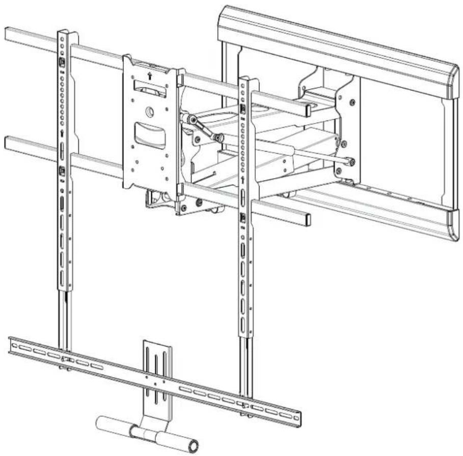
Height Adjustable Fireplace TV Mount
natural_image
Technical line drawing of a mechanical lifting device with mounting brackets and structural components (no text or symbols)MI-384L
MOUNT-IT!
INSTALLATION INSTRUCTIONS
For installation assistance or questions, please contact us at support@mount-it.com or (855) 925 5668.
WARNING
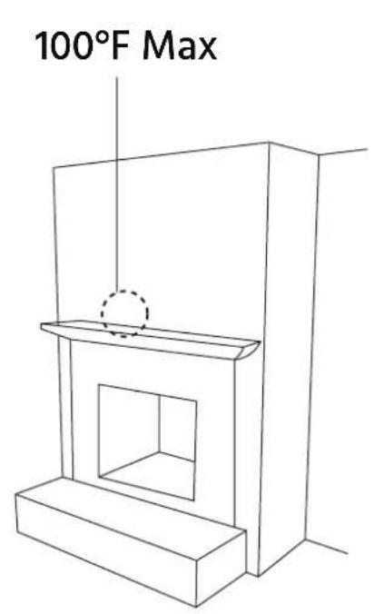
- The maximum temperature at the front of the fireplace mantle should never be more than 100^ (37.8°C).
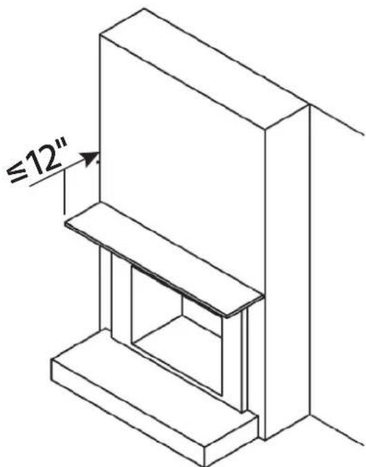
- The fireplace mantle should not extend more than 12"(304mm) from the mounting surface.
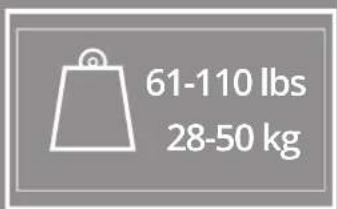
● This mount can support displays weighing between 61\~110lbs(28\~50kg). - The mounting surface should be a wood stud frame wall with studs spaced no more than 24"(609mm) apart; The wall must not exceed 5/8"(16mm) thick.
- Ensure that the mounting surface is capable of supporting the combined weight of the mount and any mounted display.
- This mount should only be installed by persons with a basic knowledge of building construction and installations.
- This bracket should only be installed by two people. Do not attempt to install it by yourself.
- If mounting to a wall of wood stud construction, ensure that mounting bolts are anchored in the center of the studs. When installing the TV mount on a concrete wall, the wall must be at least 8.0" (203mm) thick with a minimum compressive strength from 2500 to 3000 psi (17.2 to 20.7 Mpa) and must meet the ASTM C39 specification. When installing the TV mount on a cinder block wall, the cinder blocks must meet the ASTM C216 specifications and have a minimum nominal width of 8.0" (203mm). Be sure to mount it in a solid part of the block, generally 1" (25mm) minimum from the side of the block. Do not drill into mortar joints! If plaster/dry wall is thicker than 5/8" (16mm), custom fasteners must be supplied by the installer. Note that hardware and instructions are provided for installation to wood stud walls only.
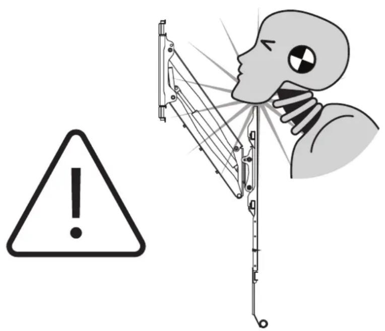

INTRODUCTION
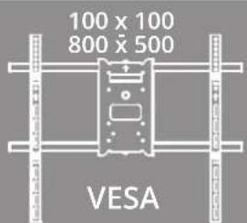
Mount your television conveniently above your fireplace using this Above Fireplace Mount. It is capable of supporting televisions with VESA patterns from 100x100 and 800x500 and weighing between 61\~110 lbs (28\~50kg). The mount allows you to keep the TV safely up and out of the way when not in use, then you can pull it down to eye level for comfortable viewing.
FEATURES
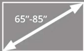
- Designed for flat screen televisions from 65" \~85"
● Supports televisions weighing between 61\~110 lbs (28\~50kg)
● Supports VESA mounting patterns between 100x100 and 800x500
● Designed to mount to wood stud frame wall above the fireplace mantle - Television can be pulled down to eye level for comfortable viewing
Full motion mount allows for ± 30^ swivel, ± 5^ rotation, and +10^ / -5^ tilt
PACKAGE CONTENTS
AA.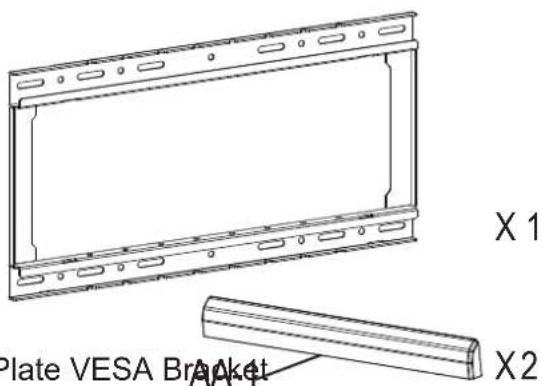 Wall F Wall F | BB.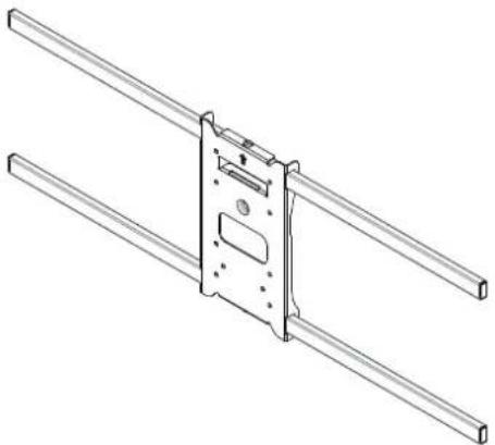 X1 X1 | |
CC.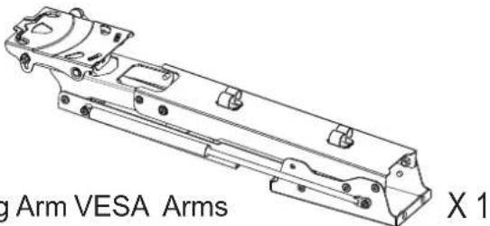 Spring Spring | DD.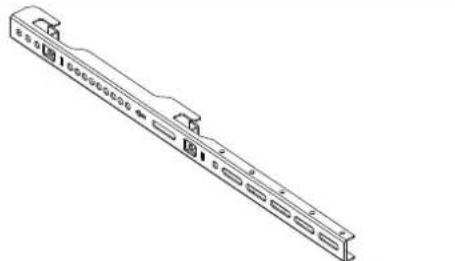 X2 X2 | |
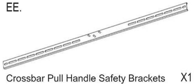 | FF.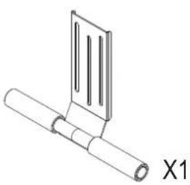 | HH.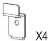 |
GG. II.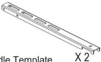 Pull Handle Complete Pull Handle Complete | 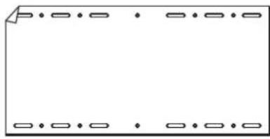 X1 X1 | |
REQUIRED TOOLS (Not Included)
You will need the following tools for installation
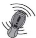
Stud Finder
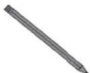
Pencil
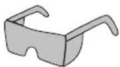
Protective Eyewear
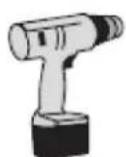
Drill
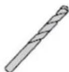
3/8"or 3/16" Drill Bit
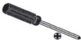
Phillips Screwdriver
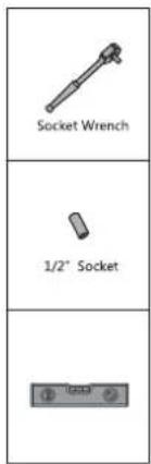
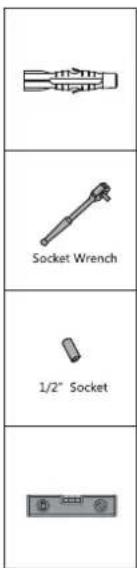
1/2" Socket
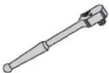
Socket Wrench
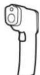
Thermometer
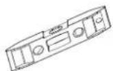
Bubble Level
INSTALLATION CONSIDERATIONS
WARNING: Please read and follow these installation considerations before beginning the installation to ensure the wall mount is compatible with your mounting location and display.
- The temperature at the front of the fireplace mantle must never exceed 100^ F ( 38^ C).
-
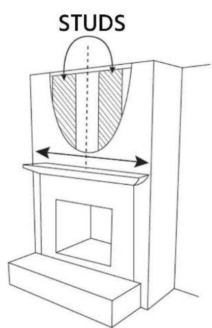
If mounting to studs, the studs must be spaced no more than 24" (609mm) apart. These studs should be symmetrically positioned, or the installation will not be even. The drywall must be no more than 5/8" thick.
-
The distance from the mesa of the fireplace to the wall must be less than 12"(30.4cm).
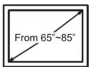
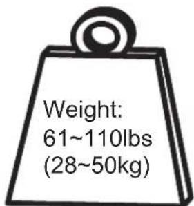
- This fireplace TV mount is designed for larger and heavier TVs. If your TV weighs less than 61 lbs, the arm may not fully lower under the weight of the TV.
[Non-Text]
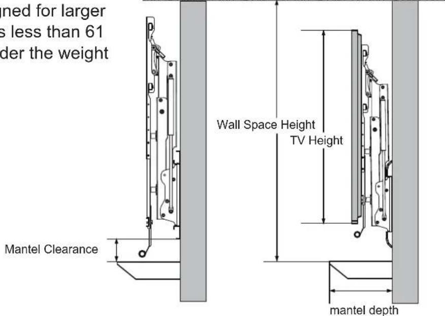
- The minimum vertical space between the bottom of the wall plate (#AA) and the top of the mantel (Mantel Clearance) will change depending on the depth of the mantel. Deeper mantels will require higher vertical clearance to ensure that the TV and the mount arm have enough clearance when raised and lowered. Refer to the table below to determine the required minimum vertical space.
| If Mantel Depth is: | Mantel Clearance Wall Space Height | |
| Less than 8” | +5” | TV height +12” |
| 8”~11” | +6.5” | TV height +13.5” |
| 11”~13” | +8” | TV height +15” |
| 13”~16” | +11” | TV height +18” |
INSTALLATION
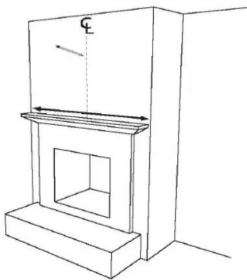
Use a tape measure to determine the center point of the mantle. Mark the centerline with a pencil or tape.
natural_image
Line drawing of a simple electrical cabinet with a vent and side-mounted base (no text or symbols)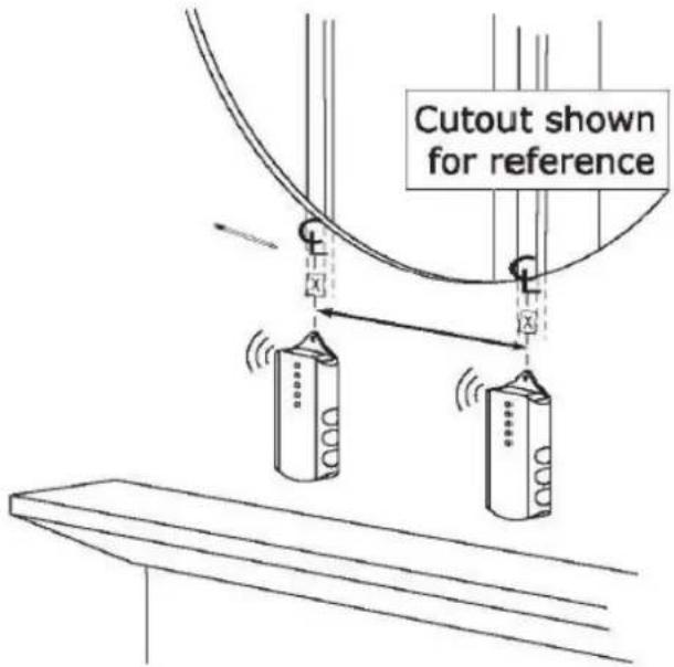
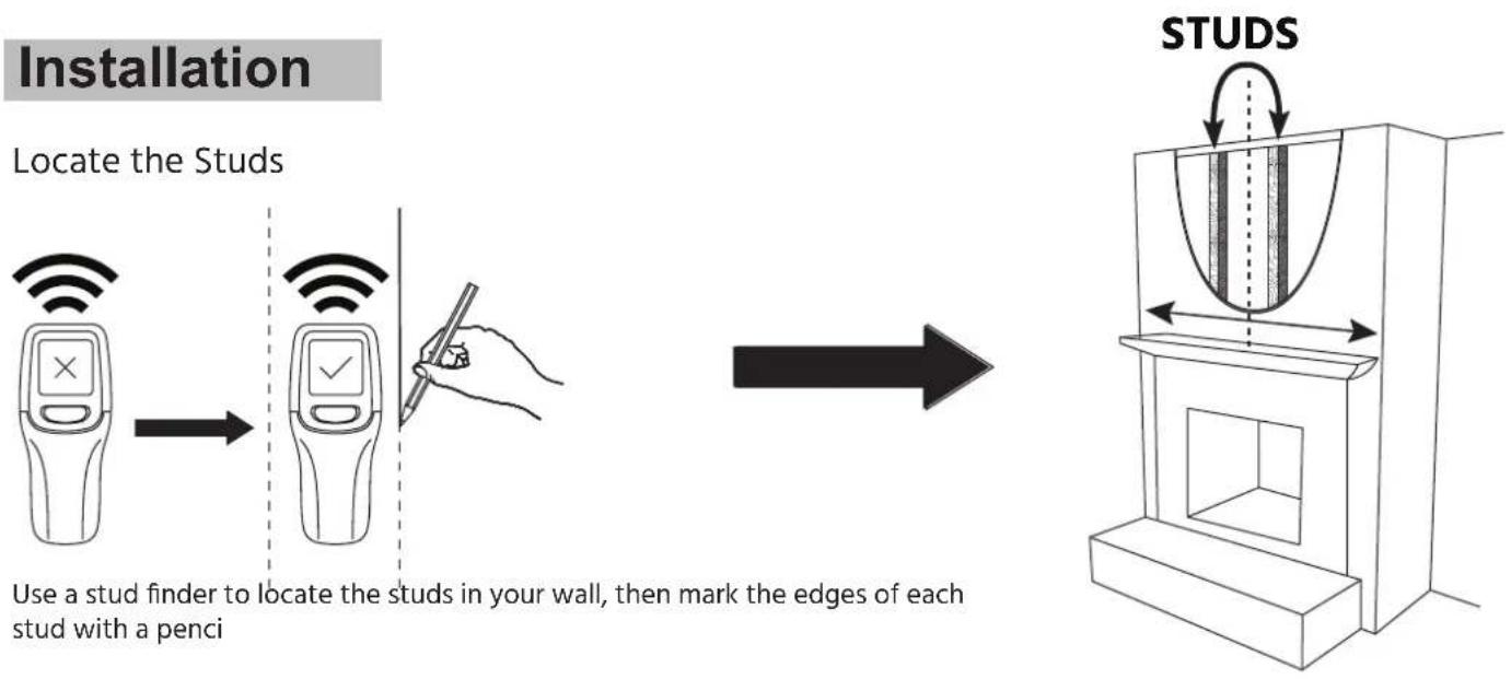
flowchart
graph LR
    A["Start: Use a stud finder to locate the studs in your wall, then mark edges of each stud with a pencil"] --> B["Place: Use a student monitor to locate the studs"]
    B --> C["End: Mark the edge of each stud with a pencil"]
    C --> D["Stud: Studs on screen with curved arrow indicating motion or movement"]
1 Wood Stud Installation Option
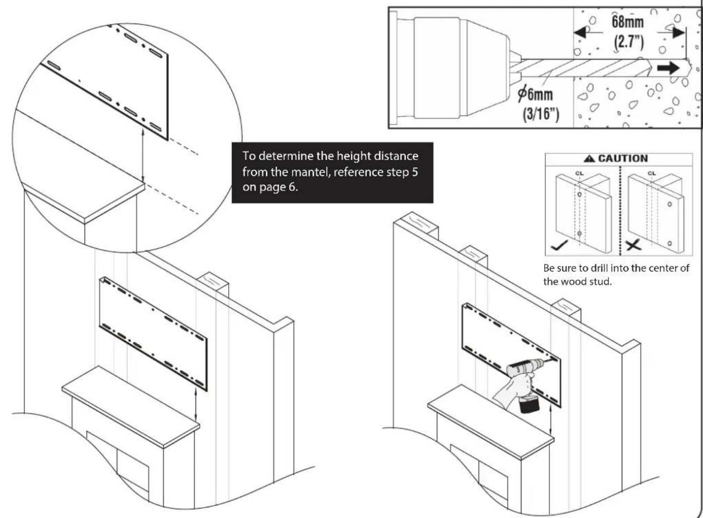
Determine the placement of the template by referencing the guide on page 6, step 5.
Use a bubble level to ensure straightness, then tape or hold the Template (#II) in the final mounting location and drill 4 pilot holes in the locations that line up with the center of the studs. Drill the pilot holes using a 3/16in drill bit to a depth of 2.7".
2 Concrete/Brick Installation Option
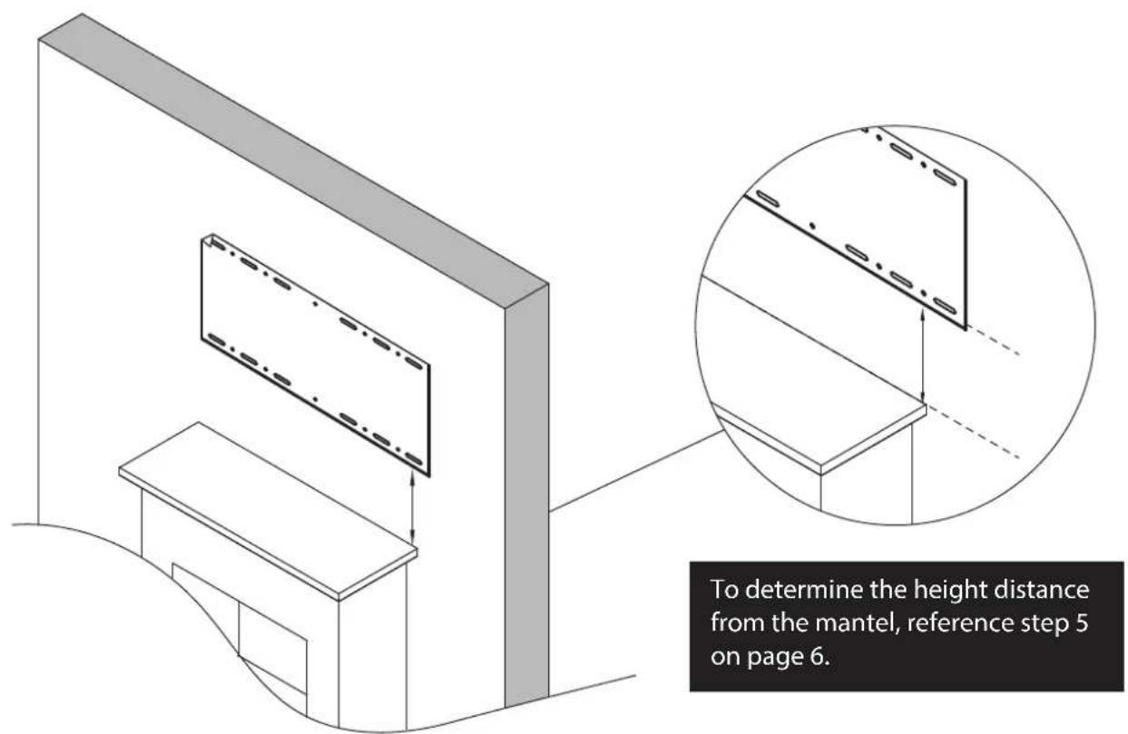
Determine the placement of the template by referencing the guide on page 6, step 5. Use a bubble level to ensure straightness, then ape or hold the Template (#II) in the final mounting location and drill 6 pilot holes, all 4 corners and 2 in the middle. Drill the pilot holes using a 3/8in drill bit to a depth of 2.7".
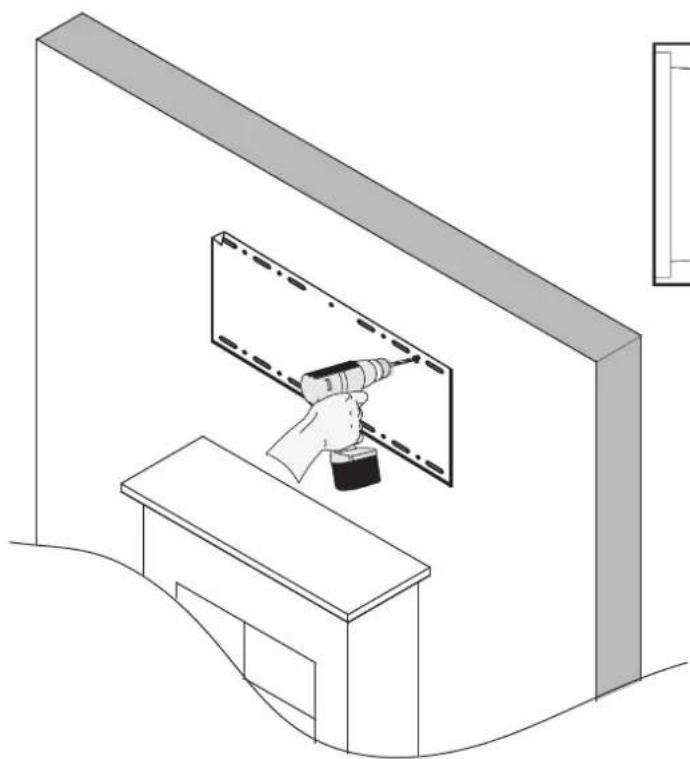
natural_image
Isometric line drawing of a hand using a power tool to clean or install a wall-mounted panel, with no text or symbols present.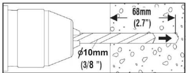
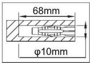
Insert Concrete Anchor (I)
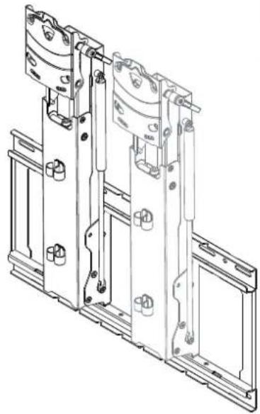
3 -a Connect the Spring Arm (#CC) to the Wall Plate (#AA) using the Bolts (#C3)as shown here.
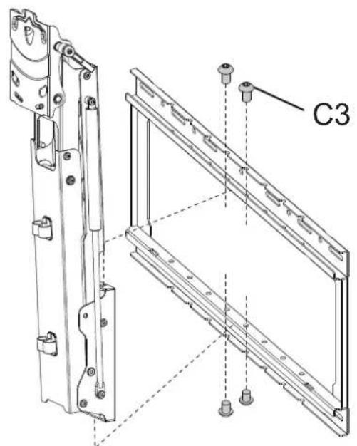
natural_image
Technical line drawing of a mechanical assembly with mounting holes and structural brackets (no text or symbols)3-b Optional: Adjust the Horizontal Position of the Spring Arm
natural_image
Technical line drawing of a mechanical assembly with mounting brackets and housing (no text or symbols)
Position the Spring Arm left or right on the Wall Plate as needed by attaching the spring arm in the required location.
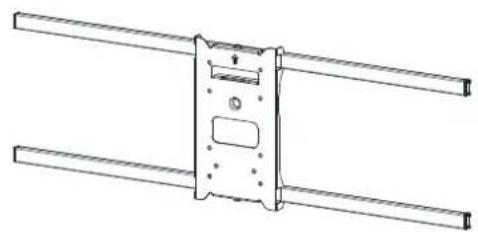
4 Hang the VESA Plate
natural_image
Technical line drawing of a mechanical assembly with two parallel rods and a central bracket (no text or symbols)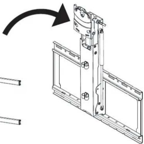
natural_image
Technical line drawing of a mechanical assembly with a rotating component and mounting brackets (no text or symbols)Hang the VESA Plate (#BB) on to the end of the Spring Arm.
5 Secure the VESA Plate
natural_image
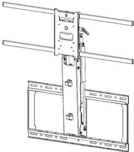
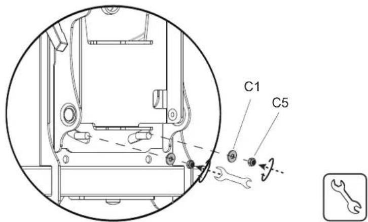
Technical line drawing of a mechanical assembly with two parallel rods and a vertical lock mechanism (no text or symbols)Secure the VESA Plate to the end of the Spring Arm using the Washers (#C1) and Nuts (#C5) on the two lower bolts protruding through the end of the Spring Arm.

-a Wood Stud Mounting
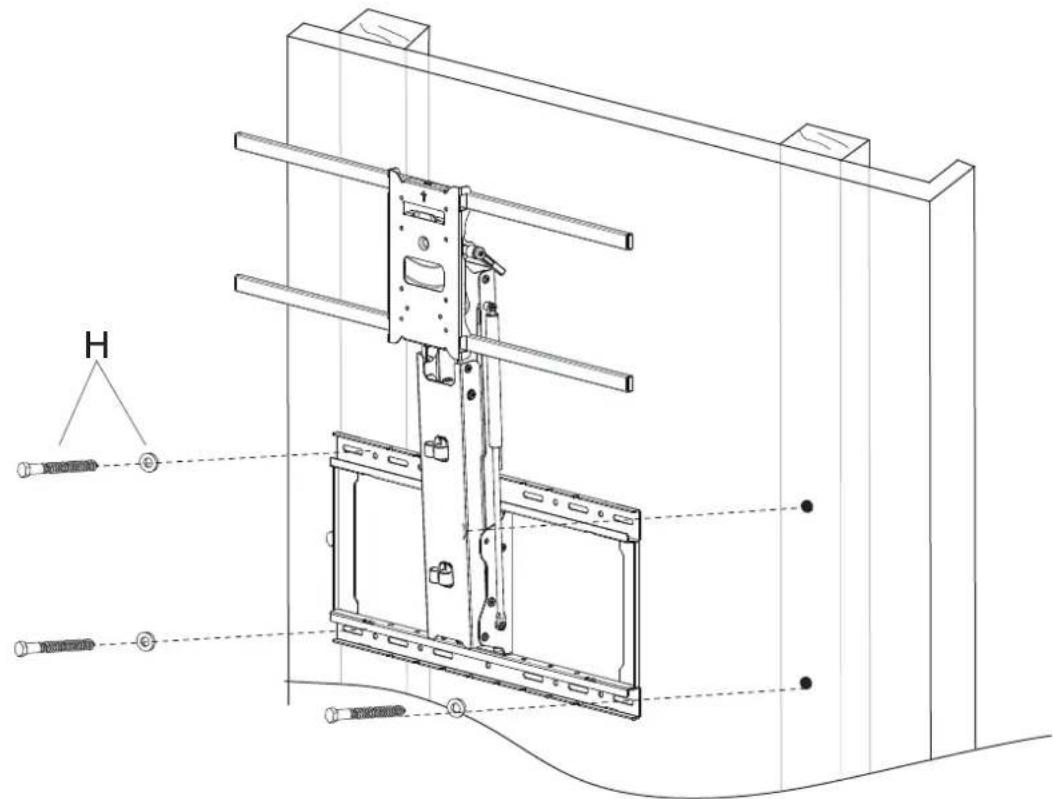
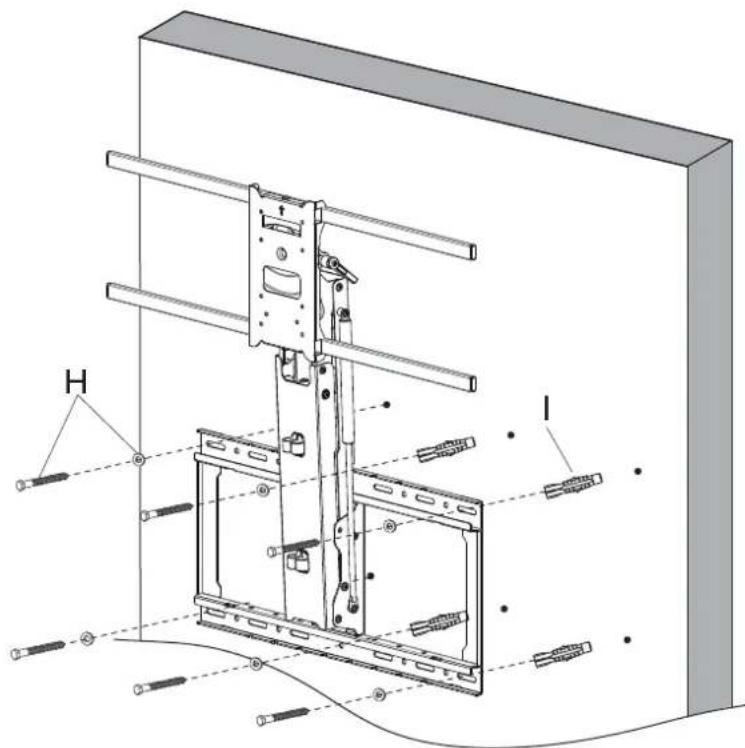
Install the assembled arm to the wall using the Lag Screws (#H) and Washers (#H) as shown.

-b Concrete/Brick Mounting
Insert the Concrete Anchors (#I) into the drilled holes, then install the assembled arm to the wall using the Lag Screws (#H) and Washers (#H) as shown.
7
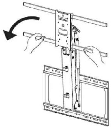
Lower the Arm
Pull the spring arm down until it is perpendicular to the wall.
natural_image
Diagram of hands operating a mechanical device with a rotating arrow indicating rotation (no text or symbols present)8
Lock the Arm
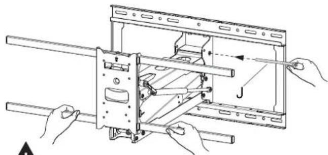
Insert the Arm Lock Pin (#K) through the holes shown here to lock the arm in the lowered position for easier access to hang the TV.
natural_image
Technical line drawing of a mechanical assembly with hands operating a bracket (no text or symbols)
Lock the arm
9
Attach the VESA Arms to the TV
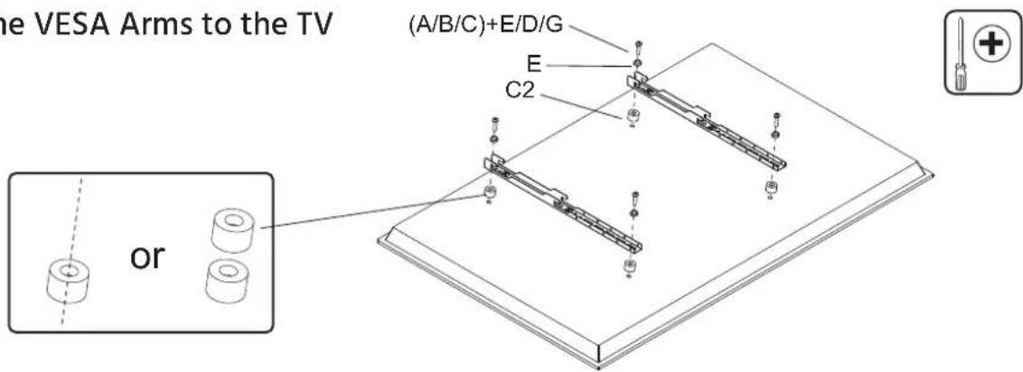
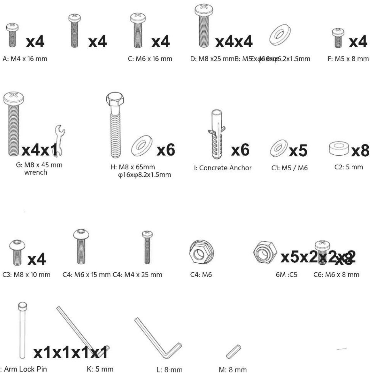
Select the appropriate size mounting bolt (Select one size #A, B or C) and washer (#E, D, or G) for your display's mounting holes and verify the length of the VESA bolt is not too long. If you are unsure of the correct bolt size for your display refer to your display's user manual or contact the display's manufacturer for sizing information. If necessary, use the included spacers (#C2) between the mount and the screen as shown to adjust the length of the mounting bolt. Multiple spacers can be used in combination to achieve the desired bolt depth. Attach the VESA Arms (#DD) using the selected bolts and tighten until secure. Do not overtighten.
10
Assemble the Crossbar
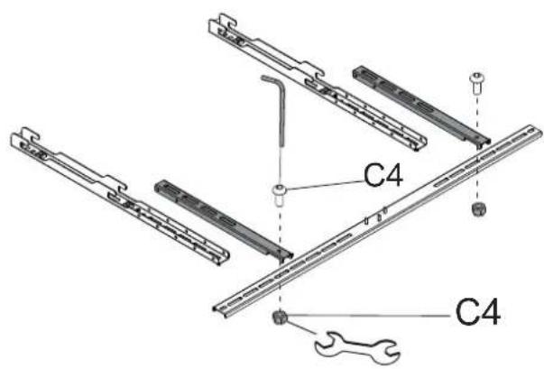
Assemble the Crossbar (#EE) by attaching the Crossbar Latches (#GG) over the bar as shown, then secure them together using the Bolts (#C4) through both pieces into the Nuts (#C4).
11
Attach the Crossbar (No Soundbar)
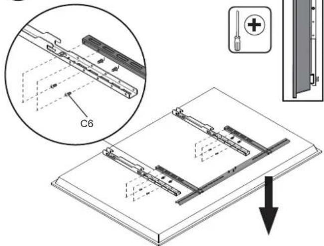
If a soundbar will not be connected to the mount attach the crossbar at a height that it is close to the bottom of the TV without being visible. Secure it to the VESA Arms using the bolts (C6) and tighten them until secure.
12 Attach the Crossbar (With Soundbar)
natural_image
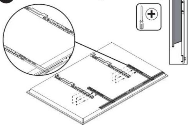
Technical diagram of a mechanical assembly with exploded view and component details (no text or symbols)To connect a soundbar to the mount, attach the crossbar so that it is below the bottom of the screen. Secure it to the VESA Arms using the bolts (C6) and tighten them until secure.
13 Attach the Soundbar
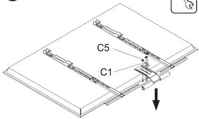
Attach the Soundbar to the bolts protruding from the back of the crossbar using the Washers (#C1) and the Nuts (#C5). Adjust the height of the handle as needed to accommodate soundbar or the screen.
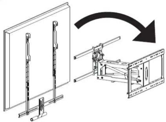
14 Hang the TV on the Mount Arm
natural_image
Technical illustration of a mechanical assembly with an arrow indicating rotation or assembly (no text or symbols present)Hang the TV onto the horizontal supports of the mount arm, ensuring that the 4 points of contact are all fully seated in their hooks.
15 Install the Safety Brackets
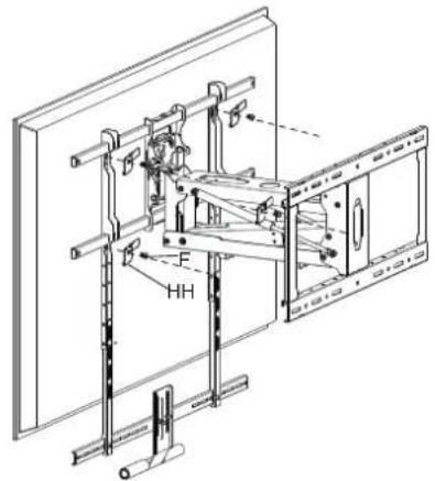
Install the Safety Brackets (#HH) using the Bolts (#F) in all 4 locations as shown here.
16 Optional Soundbar Installation
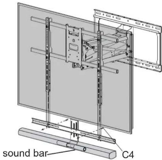
Attach the soundbar to the crossbar using the bolts (#C4) or other bolts as identified by the user manual of your device.
17
Remove the Crossbar Latch
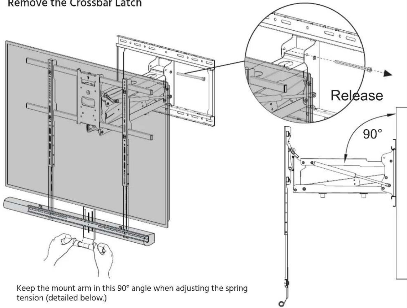
Adjusting the Spring Arm Tension
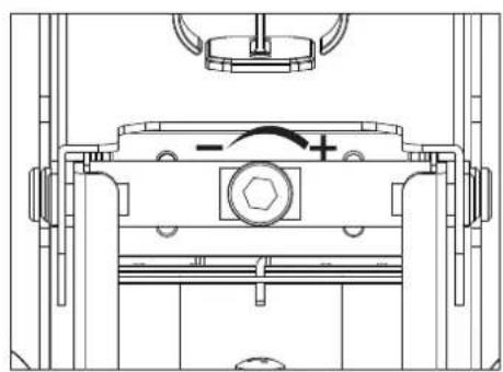
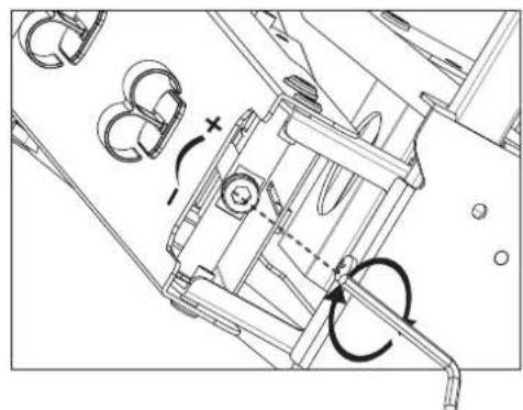
“+”: Increase Tension
natural_image
Technical line drawing of a mechanical assembly with no visible text or symbols“-” : Reduce Tension
natural_image
Technical line drawing of a mechanical assembly with no visible text or symbolsAttention:
Adjust the tension of the spring arm until it stops freely at all lowered positions.
If the arm raises on its own then turn the adjustment bolt toward the “-” symbol to decrease tension until the arm stops at the desired position.
If the arm lowers on its own then turn the adjustment bolt toward the “+” symbol to increase tension until the arm stops at the desired position.
17-2
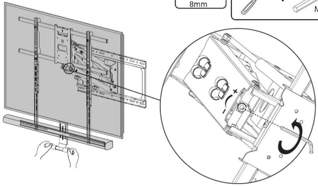
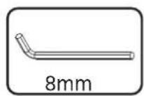
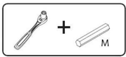
Reducing the Tension
natural_image
Simple line drawing of a wrench and a cylindrical object with plus sign, no text or symbols presentIf the arm raises on its own then turn the adjustment bolt toward the “-” symbol to decrease tension until the arm stops at the desired position.
17-3
Increasing the Tension
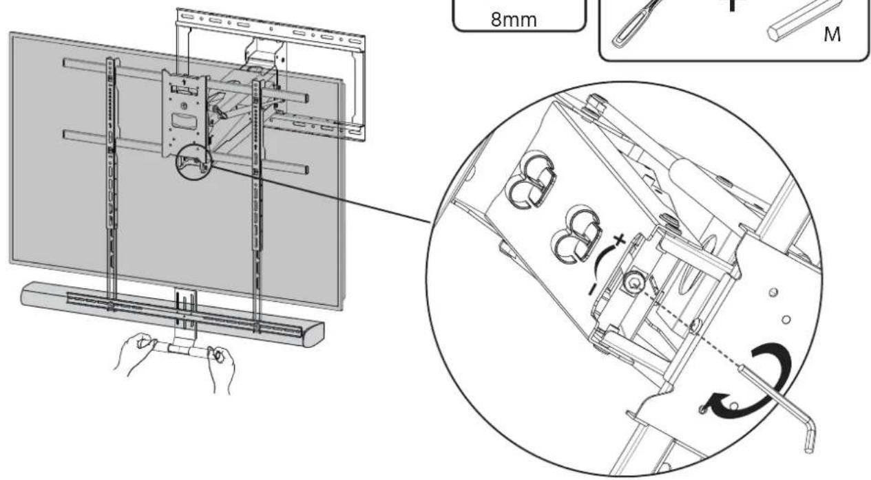
If the arm lowers on its own then turn the adjustment bolt toward the “+” symbol to increase tension until the arm stops at the desired position.
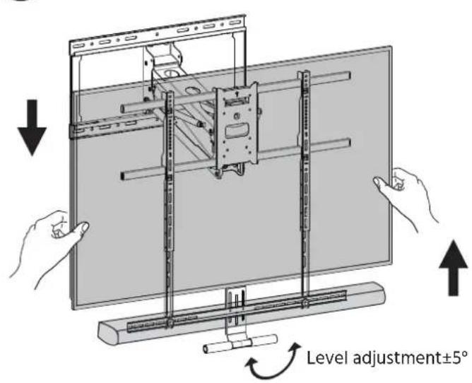
18 Level Adjustment
natural_image
Technical line drawing of a mechanical assembly with no visible text or symbols
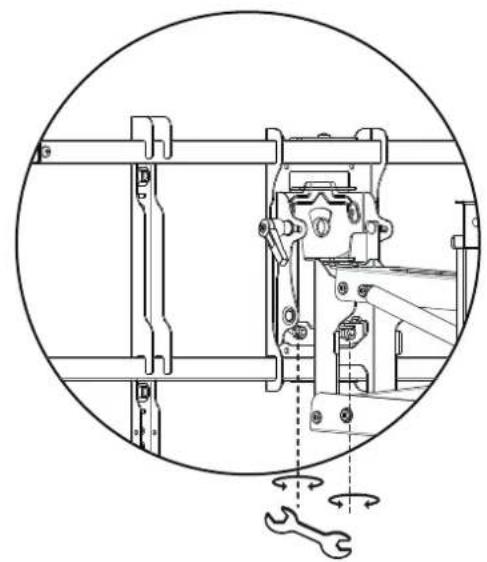
The Level of the screen can be adjusted ±5^ by loosening the nuts on the lower back of the VESA plate shown in the magnification bubble here, then adjust to the desired level and tighten the nuts back down.
19 Tilt and Swivel Adjustments
natural_image
Mechanical assembly diagram showing a lever mechanism with an arrow indicating rotational motion (no text or symbols present)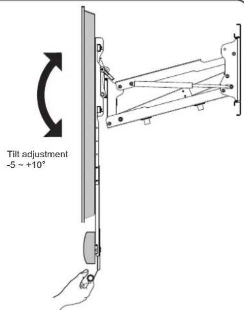
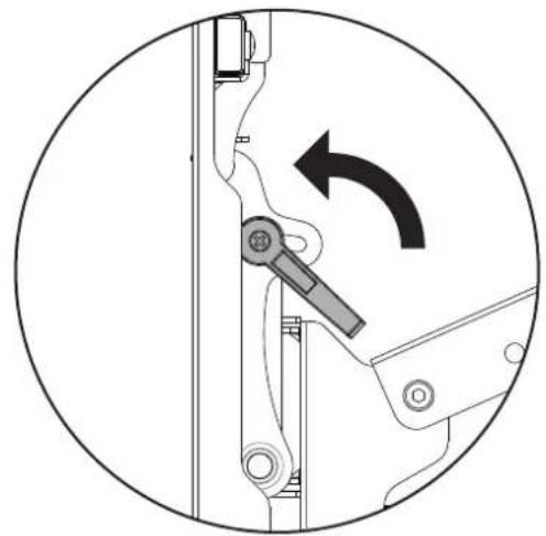
The screen can be tilted -5^ to +10^ by loosening the adjustment handle on the upper back sides of the VESA plate shown in the magnification bubble, then adjust to the desired tilt and tighten the handle back down.
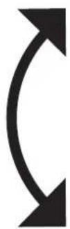
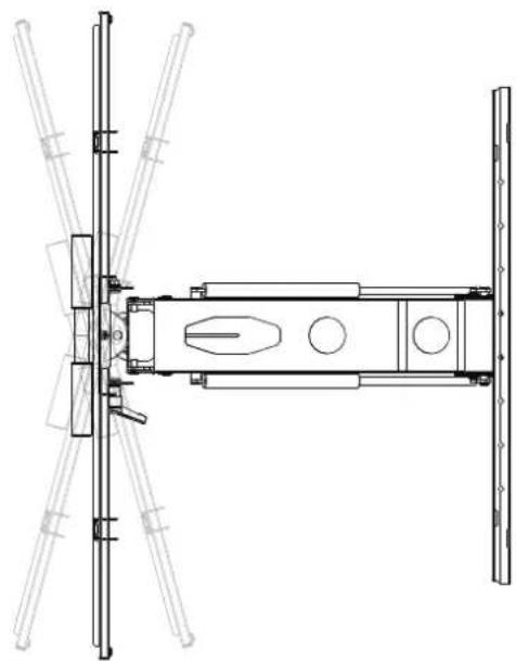
The mount arm can swivel ±30^ to adjust to the desired viewing angle.
Swivel ±30°
natural_image
Technical line drawing of a mechanical assembly with vertical supports and mounting brackets (no text or symbols)20
Cable Management
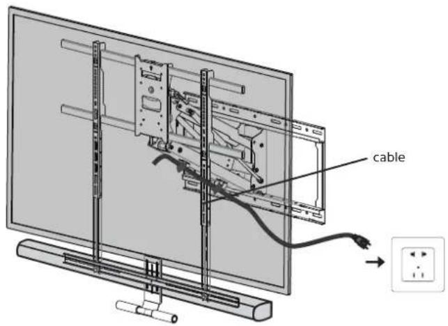
Cables can be run through the cable management clips on the underside of the mount arm to prevent the cables from hanging freely.
Note: Leave enough slack in the cables to accommodate or the range of motion of the mount.
21
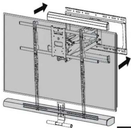
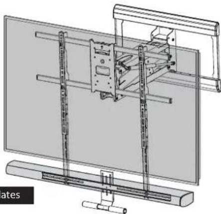
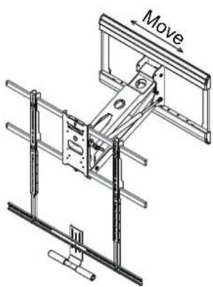
Install the Cover Plates
natural_image
Technical diagram of a mechanical assembly with no visible text or symbolsPull in the cover plates
natural_image
Technical line drawing of a mechanical assembly with no visible text or symbolsInstall the decorative Cover Plates (#AA-1) onto the top and bottom of the Wall Plate.
22
![22 886mm [34.9"] 680mm [26.8"] 609.6mm [24.0"] 406.4mm [16.0"] 203.2mm [8.0"] 100mm [3.9"] Ø8.3mm [Ø0.3"] Ø6.5mm [Ø 3"] 100mm [3.9"] 200mm [7.9"] 527mm [20.7"] 344mm [13.5"] 298mm [11.7"] 830mm [32.7"]Max 850mm [33.5"]](/content/2026/05/959155/images/234f4e63ceef06e514d4369db8d0261d9bcbb7241f101bea1bbdf6bf6321c71d.jpg)
![145mm [5.7"] 655.5mm [25.8"] 570mm [22.4"] 878mm [34.6"] +10°/-5° 735mm [28.9]~985mm [38.8] 876mm [34.57]Min-1120mm[44.3]Max UP 250mm[9.8"] Down](/content/2026/05/959155/images/c65342e47a2a01dc3662bef8ee3d4a5db5bd80c4fa7c4b50980ddfa8de2ad81b.jpg)
- Height Adjustable Fireplace TV Mount
- MOUNT-IT!
- INSTALLATION INSTRUCTIONS
- WARNING
- INTRODUCTION
- FEATURES
- PACKAGE CONTENTS
- REQUIRED TOOLS (Not Included)
- INSTALLATION CONSIDERATIONS
- INSTALLATION
- Wood Stud Installation Option
- Concrete/Brick Installation Option
- -a Wood Stud Mounting
- -b Concrete/Brick Mounting
- Lower the Arm
- Lock the Arm
- Attach the VESA Arms to the TV
- Assemble the Crossbar
- Attach the Crossbar (No Soundbar)
- Adjusting the Spring Arm Tension
- Attention:
- Adjust the tension of the spring arm until it stops freely at all lowered positions.
- 20
- Cable Management
- 21
- Install the Cover Plates
- 22
Brand : Mount-It!
Model : MI-384L
Category : Flat Screen Mount