MI-766 - Support pour écran plat Mount-It! - Free user manual and instructions
Find the device manual for free MI-766 Mount-It! in PDF.


| Product Type | Counterbalance Monitor Wall Mount |
| Brand | Mount-It! |
| Model | MI-766 |
| Mounting Options | Wood Stud and Concrete/Brick |
| Tilt Range | -45° to +90° |
| Rotation | 360° |
| Swivel | Yes per joint |
| VESA Compatibility | 75x75mm and 100x100mm |
| Weight Capacity (per arm) | Up to 33 lbs (15 kg) typical |
| Gas Spring Adjustment | Yes, by hex wrench |
| Cable Management | Yes, with removable covers |
| Hardware Included | Lag screws, concrete anchors, washers, M4 and M5 mounting bolts, washers, hex wrench |
| Installation Tools Required | Stud finder, bubble level, drill, 3/8" drill bit |
| Safety | Indoor use only; professional installation recommended; do not exceed rated weight |
| Maintenance | Check bracket security every 3 months |
| Customer Support | Phone: (855) 925-5668, Email: support@mount-it.com, Mon-Fri 8am-4pm PST |
| Parts Replacement | Free replacement for missing or faulty parts |
Frequently Asked Questions - MI-766 Mount-It!
User questions about MI-766 Mount-It!
0 question about this device. Answer the ones you know or ask your own.
Ask a new question about this device
Download the instructions for your Support pour écran plat in PDF format for free! Find your manual MI-766 - Mount-It! and take your electronic device back in hand. On this page are published all the documents necessary for the use of your device. MI-766 by Mount-It!.
USER MANUAL MI-766 Mount-It!
natural_image
Technical line drawing of a mechanical linkage assembly (no text or symbols)
Please scan this QR code to visit the product page.
COUNTERBALANCE MONITOR WALL MOUNT

HAVE QUESTIONS?
Monday - Friday from 8:00am - 4:00pm PST

support@mount-it.com

(855) 925-5668

www.mount-it.com
Thank you for choosing Mount-It!
EN Read the entire instruction manual before you start installation and assembly. If you have any questions regarding any of the instructions or warnings, please contact R'mout II for assistance.
CAUTION: Use with products heavier than the rated weights indicated may result in instability causing possible injury. - Mounts must be attached as specified in assembly instructions. Internet installation may result in damage or serious personal injury.
- Safety gear and proper lacle must be used. This product should only be installed by professorials.
- Make sure that the supporting surface will safely support the combined weight of the equipment and all attached hardware and components.
- Use the floating screws provided and DO NOT OVER THURION LOADING SCREEN.
- This product contains small items that could be a rocking instant if employed. Even
- This product contains several items that make a bonding or hazard of the product, plus a loss normal injury. Your children?
- This product is interested for indoor use only. Using this product outliers could lead to product failure and personal injury
IMPORTANT: Ensure that you have received all parts according to the component checklist prior to installation. If any parts are missing or faulty, telephone
Mount If for a replacement.
MAINTENANCE: Check that the bracket is secure and safe to use at regular intervals (at least every three months).
* We provide our pre- and post- and post- and post- and post- and post- and post- and post- and post- and post- and post- and post- and post- and post- and post- and post- and post- and post- and post- and post- and post- and post- and post- and post- and post- and post- and post- and post- and post- and post- and post- and post- and post- and post- and post
MONITOR MOUNTING HARDWARE

M-A (x8BB M4x12

M-B (x)
M5×12

M-C (x)
D5
WALL MOUNTING HARDWARE
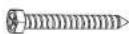
W-A (x3) ST6 7×55
516.3x55
Lag Screw Concrete Anchor

W-B (x3)
010845

W-C (x3)
Washer
Missing Parts? Call us at (855) 925-5668 and we will ship replacement parts free of charge.

Step 1a
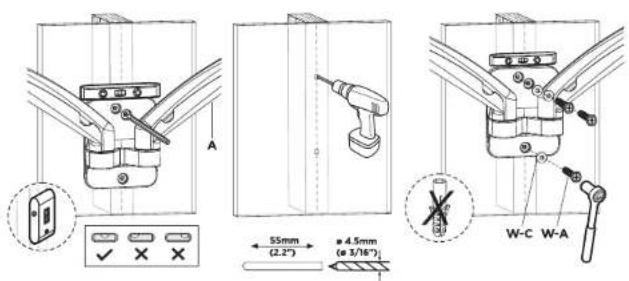
Wood Stud Mounting Option
- With a stud finder locate the stud and center the mount on the stud at the desired height. Using a bubble level to ensure straightness mark the center of the mounting holes with a pencil. - Use a 3/18" drill bit and drill on the marked locations to a depth of 2.2". Secure the Spring Arm (#A) to the wall using Lag Screw (#W-A) and Washer (#W-C). Tighten the screws until secure.
Step 1b
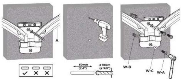
Concrete/Brick Mounting Option
- Using a bubble level to ensure straightness hold the Spring Arm (#A) to the desired location on the wall and mark the center of the mounting holes with a pencil. - Use a 3/8" drill bit and drill on the marked locations to a depth of 2.4". Clear any dust and debris from the holes and insert the Concrete Anchors (#W-B). Secure the Spring Arm (#A) to the wall using Lag Screw (#W-A) and Washer (#W-C). Tighten the screws until secure.
Step 2
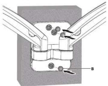
Insert Decorative Covers
- Insert the Decorative Covers (#B) into each of the bolt holes.
Step 3
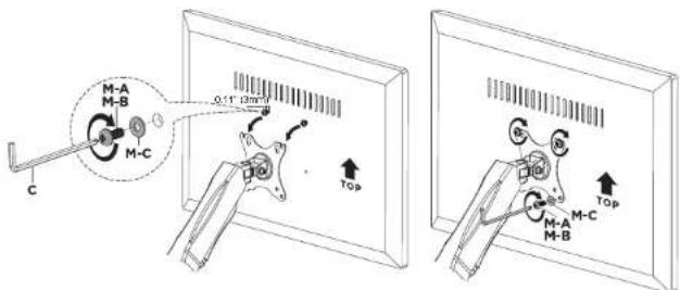
Attaching the Monitor
- Select the appropriate size mounting bolt (#M-A, M-B) for your display's mounting holes and verify the length of the VESA bolt is not too long. If you are unsure of the correct bolt size for your display refer to your TV user manual or contact the TV manufacturer for sizing information. - After selecting the appropriate bolt install the top two bolts and washers (#M-C) to the monitor leaving a gap of approximately 0.11" (3mm). Hang the monitor onto the top of the VESA plate as shown. - Install the lower two bolts and washers (#M-C) through the lower holes. Tighten all 4 bolts until secure, do not overtighten. Repeat these steps for the second monitor.

Step 4
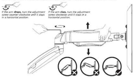
Weight Balancing the Gas Spring Arm
- Gas Spring tension may need to be adjusted to suit the weight of the monitors. To weight balance the gas spring arm, begin by pushing the arm down to the lowered position. Then use Hex Wrench C to adjust the nut as pictured above, turning counterclockwise toward the + (plus) sign for heavier monitors, increasing the tension and clockwise toward the - (minus) sign for lighter monitors, lowering the tension. Adjust until the arm does not raise back to the highest position or likewise sink to the lowest position when released. This might require multiple rotations to reach the desired tension.
Step 5
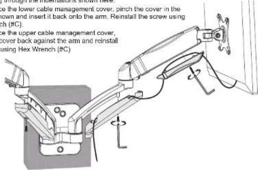
Removing Cable Management Covers
- To remove the lower cable management cover, remove the bolt using Hex Wrench (#C) and pull the cover away from the arm.
• To remove the upper cable management cover, remove the bolt using Hex Wrench (#C) and pinch the cover in the location shown and pull the cover away from the arm. - Once the cable management covers are removed, run the monitor cable beneath the covers, entering and exiting through the indentations shown here.
• To replace the lower cable management cover, pinch the cover in the location shown and insert it back onto the arm. Reinstall the screw using Hex Wrench (#C).
• To replace the upper cable management cover, press the cover back against the arm and reinstall the screw using Hex Wrench (#C)
Step 6
Final Adjustments
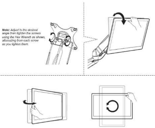
- The viewing angle can be adjusted in the range of -45° to +90°, and the screen can be rotated 360°. Each joint can swivel left or right for alternate viewing angles.
Visit us at www.mount-it.com for product registration and warranty information.
Our US based customer service team is standing by to answer any questions you have about your Mount-It! product.
Available by phone Monday - Friday from 8:00am to 4:00pm PST.
Chat live with an agent on our website!

support@mount-it.com

(855) 925-5668

www.mount-it.com
- COUNTERBALANCE MONITOR WALL MOUNT
- Thank you for choosing Mount-It!
- Step 1a
- Wood Stud Mounting Option
- Step 1b
- Concrete/Brick Mounting Option
- Step 2
- Insert Decorative Covers
- Step 3
- Attaching the Monitor
- Step 4
- Weight Balancing the Gas Spring Arm
- Step 5
- Removing Cable Management Covers
- Step 6
- Final Adjustments
Brand : Mount-It!
Model : MI-766
Category : Support pour écran plat