
TE1BQ42RS - Barbecue Twin Eagles - Free user manual and instructions
Find the device manual for free TE1BQ42RS Twin Eagles in PDF.


| Product Type | Gas Barbecue Grill |
| Brand | Twin Eagles |
| Model | TE1BQ42RS |
| Width | 42 inches (approx. 107 cm) |
| Fuel Type | Liquid Propane (LP) or Natural Gas (NG) convertible |
| Number of Burners | 4 main burners + 1 rotisserie burner (estimated) |
| Cooking Area | Approx. 840 sq. in. main + 200 sq. in. warming rack (total ~1040 sq. in.) |
| BTU Output | Main burners: approx. 60,000 BTU total |
| Ignition Type | Electronic ignition with battery |
| Construction | Stainless steel body and burners |
| Weight | Approx. 150 lbs (68 kg) |
| Dimensions (L x W x H) | 42 x 22 x 47 inches (approx. 107 x 56 x 119 cm) |
| Warming Rack | Included, stainless steel |
| Rotisserie Kit | Included (motor and rod) |
| Side Burner | Not included (optional) |
| Grates | Stainless steel cooking grates |
| Temperature Gauge | Built-in lid thermometer |
| Installation | Freestanding or built-in compatible |
| Warranty | Lifetime on burners, 10 years on other parts (typical Twin Eagles) |
| Cleaning | Stainless steel cleaner recommended; burners removable for cleaning |
| Safety Features | Gas shut-off valve, flame failure protection on all burners |
| Spare Parts Availability | Available through Twin Eagles dealers or online |
| Manual | Free download from notice-facile.com |
Frequently Asked Questions - TE1BQ42RS Twin Eagles
User questions about TE1BQ42RS Twin Eagles
0 question about this device. Answer the ones you know or ask your own.
Ask a new question about this device
Download the instructions for your Barbecue in PDF format for free! Find your manual TE1BQ42RS - Twin Eagles and take your electronic device back in hand. On this page are published all the documents necessary for the use of your device. TE1BQ42RS by Twin Eagles.
USER MANUAL TE1BQ42RS Twin Eagles
natural_image
Silhouette of two birds in flight within a red triangular frame (no text or symbols)TWIN EAGLES
INNOVATION AND INSPIRATION ON FIRE™
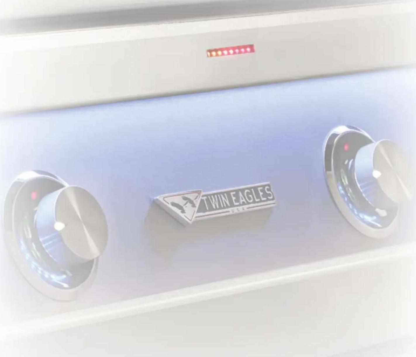
INSTALLATION, USE AND CARE MANUAL
MODELS:
TE1BQ36RS
TE1BQ42RS
TE1BQ54RS
A SPECIAL MESSAGE TO OUR CUSTOMERS...
Congratulations on the purchase of your Twin Eagles grill! Our products are engineered for precision and designed for style. Each Twin Eagles grill is manufactured in the USA at our own state of the art facility in California.
This manual will give you easy to follow instructions for installing, operating and maintaining your grill. We recommend reading this manual before your first use to ensure safety, proper care and operation.
At Twin Eagles, we want you to enjoy grilling and spending time together as much as we do – making memories that linger long after the grill cools down.
Thank you and welcome!
Dante Cantal
OWNER AND FOUNDER
TABLE OF CONTENTS CUSTOMER CARE
GETTING STARTED 1
ASSEMBLY INSTRUCTIONS 2
BURNER INSTALLATION 3
AIR SHUTTER ADJUSTMENT 4
FEATURES
GAS SAFETY REQUIREMENTS 7
LP GAS HOOK-UP 8
PORTABLE LP CONNECTION 9
NATURAL GAS INSTALLATION 10
CHECKING / CONVERTING THE REGULATOR 10
LEAK TEST 11
ELECTRICAL REQUIREMENTS 12
GRILL CUT-OUT DIMENSIONS 16
OPERATING INSTRUCTIONS 17-19
CLEANING & MAINTENANCE 20-22
EAGLE ONE EXPLODED VIEW 23
REPLACEMENT PARTS LIST 24-27
WIRING DIAGRAM 28
TROUBLESHOOTING GUIDE 29
WARRANTY 30
HOW TO OBTAIN SERVICE 31
Please record the product information below and refer to it when contacting Twin Eagles.
This information is found on the data nameplate, located on the bottom right hand side of the firebox near the regulator. A second label with model number and serial number is located under the right side of the control panel. Remove the drip tray to visually access the nameplate from the front of the grill.
SERVICE INFORMATION
Model Number
Serial Number
Date of Purchase
Place of Purchase
Type of Gas

NG LP


Intertek

To the Installer:
Please read these instructions completely before installation and give this manual to the owner.
To the Owner:
Keep this manual in a safe place for future reference.
IMPORTANT SAFETY INSTRUCTIONS
WARNING! Read this manual carefully and completely before using your grill to ensure proper operation, proper installation, proper servicing and to reduce the risk of fire, burn hazard and/or other injury.
- Shut off gas to the appliance.
- Extinguish any open flames.
- Open lid.
- If odor continues, keep away from the appliance and immediately call your gas supplier or fire department.
AVERTISSEMENT
- Do not store or use gasoline or other flammable vapors and liquids in the vicinity of this or any other appliance.
- An LP cylinder not connected for use shall not be stored in the vicinity of this or any other appliance.
AVERTISSEMENT
- Read instructions before lighting.
- Open lid during lighting.
- If ignition does not occur in 5 seconds, turn the burner control(s) off, wait 5 minutes, and repeat the lighting procedure.
AVANT D'ALLUMER L'APPAREIL
Electrical Grounding Instructions: This outdoor gas cooking appliance is equipped with a three prong (grounding) plug for your protection against shock hazard and should be plugged directly into a properly grounded three prong outlet. Do not cut or remove the third prong from this plug.
AVERTISSEMENT
- The installation of this appliance must conform with local codes or, in the absence of local codes, either the National Fuel Gas Code, ANSI Z223.1/NFPA 54, Natural Gas and Propane Installation Code, CSA B149.1 or Propane Storage and Handling Code, B149.2
- The utilization of an external electrical source requires that when installed, this outdoor cooking gas appliance must be electrically grounded in accordance with the local codes or, in the absence of local codes, with the National Electrical Code, ANSI/NFPA 70, or the Canadian Electrical Code, CSA C22.1. Keep any electrical supply cord and the fuel supply hose away from any heated surfaces.
- This outdoor cooking gas appliance shall be used only outdoors and shall not be used in a building, garage or any other enclosed area.
- This outdoor cooking gas appliance is not intended to be installed in or on recreational vehicles and /or boats.
- Minimum clearance of 12 inches from the back and sides of the grill to adjacent combustible construction must be maintained. This outdoor cooking gas appliance shall not be located under overhead-unprotected combustible constructions. (Note: To minimize the possibility of discoloration on adjacent construction extending above the counter-top surface due to grease and hot vapors, it is highly recommend-
ed that a clearance of 18 inches be maintained from sides and back of the grill.)
- Keep your grill in an area clear and free from combustible materials, gasoline and other flammable vapors and liquids.
- DO NOT obstruct the flow of combustion and ventilation air to this appliance. Keep the ventilation openings of the cylinder enclosure free and clear from debris.
- Check flexible hoses for cuts and wear that may affect the safety before each use.
- Check all gas connections for leaks with soapy water solution and brush. Never use an open flame. (Reference page 9 for leak test procedure).
- Never use charcoal in the grill unless using with a Twin Eagles Charcoal Tray (TECT).
- Always use caution when operating the grill in a windy area (For reference, see Page 12 – Windy Condition)
- Never use the grill without the drip pan installed and push all the way to the back of the grill. Without the drip pan, hot grease and debris could leak downward and produce a fire hazard.
- The pressure regulator and hose assembly supplied with the Twin Eagles Gas Grill must be used. Replacement pressure regulators and hose assemblies must be those specified by Twin Eagles.
WARNING: CALIFORNIA PROPOSITION 65
This product can expose you to chemicals including carbon monoxide which is known to the State of California to cause cancer and reproductive harm. To minimize exposure to the by-products of the burning fuel or from combustion, always operate this unit according to the use and care manual and provide good ventilation. California law requires businesses to warn customers of potential exposure to such substances. For more information go to www.P65Warnings.ca.gov.
⚠ AVERTISSEMENT: PROPOSITION 65 DE L'ETAT DE LA CALIFORNIE
In Massachusetts: All gas products must be installed using a “Massachusetts” licensed plumber or gas fitter. A “T” handle type manual gas valve must be installed in the gas supply line to this appliance. This applies to permanently installed natural gas and propane installations. This does not apply to propane portable installations using a 20-pound tank.
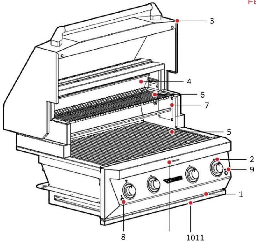
FEATURES:
- PRODUCT RATING PLATE
- KNOB AND BEZEL
- HOOD
- INFRARED GLASS ASSEMBLY
- BURNER GRATES
- WARMING RACK
- ROTISSERIE ROD
- INTERIOR LIGHT AND AMBI-ENT ILLUMINATION SWITCH
- ROTISSERIE SWITCH
- DRIP TRAY
- TEMP TRACK

natural_image
Close-up of a coiled industrial machine with blue glass panels and metallic tubing (no visible text or symbols)GRILL U-BURNER (STANDARD) LOCATED UNDERNEATH THE BRI- QUETTE TRAYS

natural_image
Close-up of illuminated industrial heat sinks with grid patterns (no text or symbols visible)natural_image
Close-up of a kitchen appliance with red LED display and metal rack (no visible text or symbols)INFRARED ROTISSERIE BURNER
BEHIND GLASS
LOCATED IN THE REAR PANEL ABOVE THE HEX GRATES
- Remove all packaging materials, labels and protective plastic film. DO NOT LEAVE UNIT IN THE SUN WITH PROTECTIVE PLASTIC FILM ON FOR AN EXTENDED PERIOD OF TIME AS IT WILL BECOME DIFFICULT TO REMOVE.
- Check to ensure all grill accessories listed below are included.
| GRILL ACCESSORIES TE1 | BQ36RSN TE1B | Q36RSL TE1BQ42 | RSN TE1BQ42RSL | TE1BQ54RSN TE1 | BQ54RSL | |
| BASTING PAN | 1 1 1 1 | 2 2 | ||||
| HEX GRATE | 3 3 3 3 | 4 4 | ||||
| LARGE BRIQUETTE ASSEMBLY | 1 1 1 1 | 2 2 | ||||
| SMALL BRIQUETTE ASSEMBLY | 2 2 2 2 | 2 2 | ||||
| REGULATOR, NG (NG GRILL ONLY) | PRE-INSTALLED | |||||
| REGULATOR, LP (LP GRILL ONLY) | - 1 - 1 - | 1 | ||||
| WARMING RACK | 1 1 1 1 | 1 1 | ||||
| ROTISSERIE ROD | 1 1 1 1 | 1 1 | ||||
| MEAT HOLDER (PAIR) | 1 1 1 1 | 2 2 | ||||
| SMOKER BOX ASSEMBLY | 1 1 1 1 | 1 1 | ||||
- Assemble parts as per assembly instructions on page 2-3.
- Fill out Warranty Registration Card and mail it to the indicated address, or register online. See page 31.
ASSEMBLY INSTRUCTIONS
Your Eagle One grill is fully assembled and tested in the factory and requires no major assembly in the field. For the purpose of safe shipping and transit, some parts such as the briquette trays and rotisserie components are wrapped inside the grill and require minor assembly.
TO INSTALL BRIQUETTE TRAYS
- Put briquette trays into the grill above the burner, as shown by placing the flash-tube-hole on the front.
- Place the hexagonal grates directly above the briquette trays and make sure the square openings on the grates are at the front.
TO INSTALL / USE THE SMOKER BOX
- Lift open smoker box lid and add soaked wood chips with water.
- Remove a hex grate. Remove a 12 sized briquette tray where there is no flash tube.
- Place the smoker box in place of the briquette tray and the smoker box will always line-up on top of the burner flame. Place hex grate back over the smoker box. Turn on grill to HIGH heat. Once smoking starts, turn the heat down to prevent wood flare-up. The Smoker box is standard on all grills.
- WARNING: Do not use smoker box over the sear burner.
WARMING RACK POSITIONS
- The warming rack may be used at a HI and LOW level position. The HI level is further away from the heat source while the lower level position is closer to the heat source.

natural_image
Three-panel image showing a stainless steel appliance with open lid, a side view of a gridded metal grille, and a close-up of its interior panel with visible wood shavings (no text or symbols)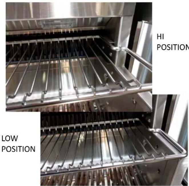
BURNER INSTALLATION
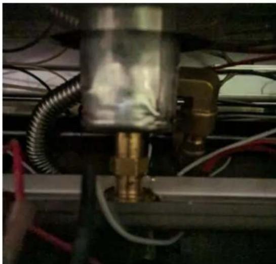
CORRECT BURNER INSTALLATION
natural_image
Close-up of a mechanical assembly with brass fittings and wiring (no visible text or symbols)The orifice is completely inserted into the venturi.
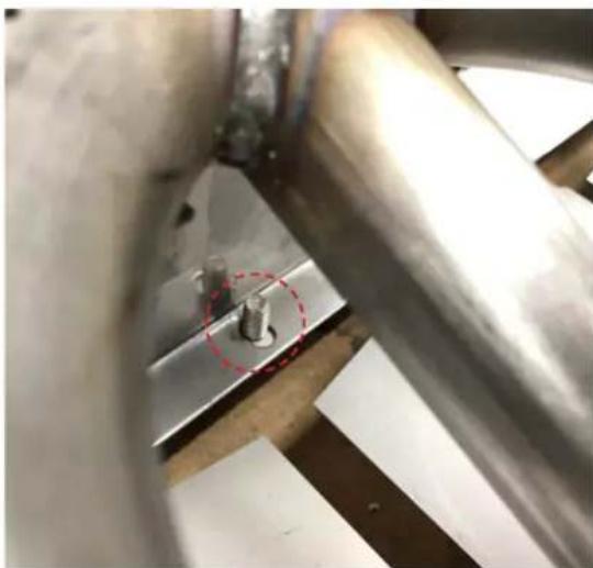
natural_image
Close-up of a metallic mechanical component with two bolts and a red dashed circle highlighting a detail (no text or symbols visible)U-burner bracket in proper position on the threaded stud.
INCORRECT BURNER INSTALLATION
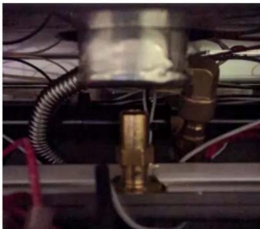
natural_image
Close-up of a mechanical assembly with brass fittings and wiring (no visible text or symbols)The venturi is out of position and the orifice is not inserted into the venturi.

natural_image
Close-up of a metallic mechanical component with a red dashed circle highlighting a bolt detail (no text or symbols visible)Burner is out of position. The threaded stud must be inserted into the bracket of the burner and secured with a 1/4-20 keps nut.
AIR SHUTTER ADJUSTMENT
Each grill burner is tested and adjusted at the factory prior to shipment; however, variations in the local gas supply may make it necessary to adjust the burners. The flames of the U-burners should be visually checked. Flames should be blue and stable with little to no yellow tips, no excessive noise or lifting. If any of these conditions exist, remove the burner and check to see if any air shutter or burner ports are blocked by dirt, debris, spider webs, etc. if it is clear, the air shutter may need to be adjusted.
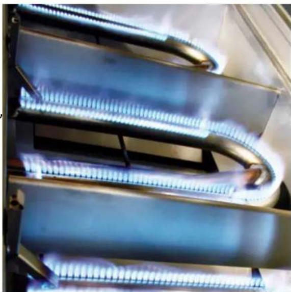
natural_image
Close-up of coiled glass tubes with blue liquid, emitting vapor or heat (no text or symbols visible)The amount of air is controlled by a sheet metal cup at the inlet of the burner called an air shutter. It is locked in place by a set screw which must be loosened prior to lighting the burner for adjustment. The air shutter adjustment screws are accessible with a phillips screwdriver. Loosen the lock screw of the air shutter. Adjust according to the following directions. Be careful as the burner may be very hot.
- If the flame is yellow, indicating insufficient air, turn the air shutter counter-clockwise to allow more air to the burner.
- If the flame is noisy and tends to lift away from the burner, indicating too much air, turn the air shutter clockwise.
Remember to tighten the set screw prior to re-installing the burner.
ENSURE THAT THE BURNERS ARE SITTING PROPERLY ON THE ORIFICES BEFORE LIGHTING THE BURNERS.

natural_image
Close-up of a metallic cylindrical object with a pointed tip and a small hole, mounted on a metal bracket (no visible text or symbols)SET TO LP SET TO NG

natural_image
Close-up of a metallic cylindrical object with a star-shaped indentation and a small hole, against a plain background (no text or symbols visible)FEATURES
Your Twin Eagles Eagle One Grill is equipped with many new and advanced features that put it at the forefront of at home grilling technology. Understanding these features and how they function is critical to maintaining the functionality of these features. Below are descriptions of these new grill features and how they integrate into your grilling experience.
TEMP TRACK
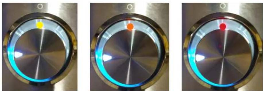
The Temp Track provides a visual representation of the average temperature inside the grill when the hood is in the closed position. The temperatures represented by the lights are to be used as reference. The yellow LED's indicate low range grilling temperatures. The orange LED's indicate mid range and average grilling temperatures, and lastly the red LED's indicate high heat or searing temperatures.

130irc 300irc 450irc 600irc
*The last LED illuminates at 600°. The grill surface can reach 900° or more.
The Ambient Illumination sits in the landing ledge of the front panel. To turn the light ON/OFF use the light switch for the halogen lights located to the left most side of the front panel. The Ambient Illumination provides soft ambient light for evening and night time grilling.
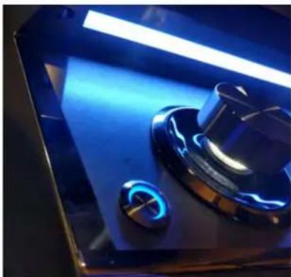
natural_image
Close-up of a kitchen sink with blue lighting and a circular button, no visible text or symbols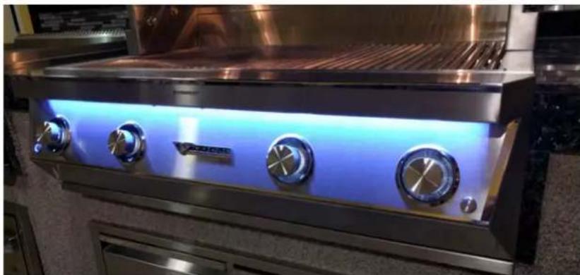
natural_image
Exterior view of a stainless steel electric stove burner with four rotary controls and a blue-lit interior (no visible text or symbols)EXACT CONTROL ILLUMINATION
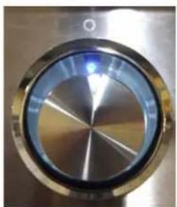
The bezels of the Eagle One Grill have LEDs in them to give a visual representation of the heat setting of the burner. The grill is in stand-by when not in use; to wake the system, simply press in a knob. A blue light will appear above the knob and the back lights will come on. The back lights have a fade out feature, after remaining lit for 20 seconds they fade to black over five seconds.
System Awake
natural_image
Close-up of a metallic circular dial with radial markings (no visible text or symbols)
natural_image
Close-up of a metallic circular dial or knob with radial markings (no visible text or symbols)System awake, lights stay lit for 20 seconds

natural_image
Close-up of a metallic circular component with concentric rings and central reflective surface (no text or symbols visible)Lights fade to black, System goes into Stand-by
The bezels of the Eagle One Grill have a light up flame intensity lights along the left side of the knob. When all six LEDs are lit, the burner is at the high heat setting. When only a single LED is lit and the knob is turned fully to the left the burner is in the low heat setting.

The blue LED that comes on when the knob is pressed means the grill is awake and ready for use. These blue LEDs will change color from blue to yellow, to orange, and then to red. These colored LEDs indicate the relative temperature for that bezel's burner zone. Yellow is low, orange is medium, and red is high temperatures.
natural_image
Three circular industrial gauges with glowing blue and red components, showing different states of heat or vibration (no text or symbols visible)YELLOW ORANGE RED 130°F - 300°F 300°F - 450°F 450°F - 600°F+
Each appliance is set and tested at the factory for the type of gas supply to be used. Identify the type of gas, either natural gas (NG) or Liquid Propane (LP) gas and make sure that the marking on the data plate (rating plate) matches the gas being supplied to the grill. This information is found on the data nameplate, located on the bottom right hand side of the firebox near the regulator. A second label with model number and serial number is located under the right side of the control panel on the fire box. Remove the drip pan to visually access the nameplate from the front of the grill.
All gas connections should be made by a qualified technician and in accordance with local codes and ordinances. The installation must conform with local codes or, in the absence of local codes, with either the National Fuel Gas Code, ANSI Z223.1/NFPA 54, Natural Gas and Propane Installation Code, CSA B149.1 or Propane Storage and Handling Code, B149.2.
WARNING:
ENSURE THAT THE GAS SUPPLY HOSE DOES NOT COME IN CONTACT WITH ANY HOT SURFACE OF THE GRILL.
NEVER CONNECT THE GRILL TO AN UNREGULATED GAS SUPPLY.
L.P. GAS SAFETY REQUIREMENT
The LP-gas supply cylinder must be constructed and marked in accordance with the Specifications for LP-gas Cylinders of the U.S. Department of Transportation (D.O.T.) or the National Standards of Canada CAN/CSA-B339, Cylinders, Spheres and Tubes for the Transportation of Dangerous Goods, and Commission, as applicable; and
- Provided with a listed overfilling prevention device.
-
Provided with a cylinder connection device compatible with the connection for outdoor cooking appliances.
-
It must be provided with a shut-off valve terminating in gas tank valve outlet. It must include a collar to protect the cylinder valve. The cylinder supply system must be arranged for vapor withdrawal.
- Do not operate the gas grill indoors or in any enclosed area. If the gas grill is not in use, the gas must be turned off at the supply cylinder. If the grill is to be stored indoors, disconnect the gas supply cylinder and leave the cylinder outdoors out of reach of children and must not be stored in a building, garage or any other enclosed area.
natural_image
Coiled black gas hose with attached metallic valve and blue control knob (no text or symbols visible)IMPORTANT NOTE:
Permanent plumbed LP connections, such as those with a bulk cylinder, require a regulator that is convertible from LP to NG. (Part Number: S15303)
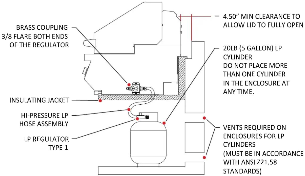
CAUTION:
PROVIDE ADEQUATE VENTILATION HOLES IN THE ENCLOSURE FOR SAFETY PURPOSES IN THE EVENT OF A GAS LEAK.
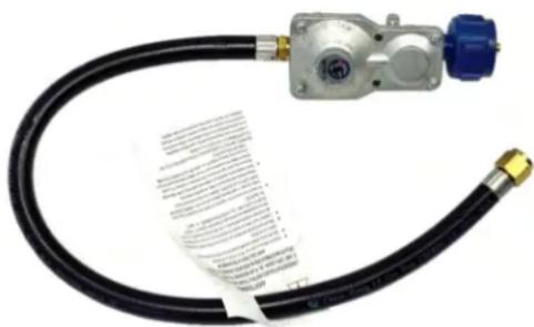
Install the factory-supplied hose and regulator assembly as shown. Connect the 3/8" flare end of the hose to the grill coupling using a 34 " open wrench. Do not apply pipe sealant to the 3/8" flare connection. Connect the regulator to the LP cylinder hand tighten it, do not use a wrench. Check for leaks using a soapy water solution. (Reference page 11 for leak test procedure).
Important Note:
An enclosure for LP gas cylinder must be vented on the level of the cylinder valve and at floor level. The effectiveness of the opening(s) for purposes of ventilation shall be determined with the LP gas supply cylinder in place. This shall be accomplished by one of the following:
• One side of the enclosure shall be fully open; or
- For a cylinder enclosure having four sides, a top and a bottom, and intended for installation in a built-in enclosure:
- At least one ventilation opening shall be provided on the exposed exterior side of the enclosure located within 5 in (1.27mm) of the top of the enclosure and unobstructed. The opening(s) shall have a total free area of not less than 1 in 2 /lb (14.2 cm 2 /kg) of stored fuel capacity.
- At least one ventilation opening shall be provided on the exposed, exterior side of the enclosure 1 in. (25.4 mm) or less from the floor level and shall have a total free area of not less than 12 in 2 /lb (7.1 cm 2 /kg) of stored fuel capacity. The upper edge shall be no more than 5 in (127 mm) above the floor level.
- Every opening shall have a minimum dimension so as to permit the entrance of 1/8 in (3.2 mm) rod.
PORTABLE LP CONNECTION
One of the many features of the Twin Eagles grill base is the pullout slide pan for easy access to the LP gas tank.
- To install the gas cylinder, pull out the slide pan and place the cylinder onto the pan.
- Tighten the tank holding screw to secure the gas cylinder in place.
- Check to ensure that the tank's gas valve on top of the cylinder is closed.
- Connect the LP regulator (included) to the cylinder and hand-tighten only. Open the tank valve and make sure all connections are leak tight using a soapy water solution. (Reference page 11 for leak test procedure).

natural_image
Close-up of a metallic mechanical component with a large white spherical object above it, marked by a red circle (no visible text or symbols)- NOTE: use only a 20-lbs (5 gallon capacity) gas cylinder,
• WARNING: DO NOT USE A DENTED OR RUSTED LP CYLINDER - NEVER USE A CYLINDER WITH A DAMAGED VALVE.
• ALWAYS CHECK FOR LEAKS AFTER CHANGING THE LP CYLINDER. - THE LP PRESSURE REGULATOR AND HOSE SUPPLIED WITH THIS UNIT MUST BE USED WITHOUT ALTERATION.

natural_image
White gas cylinder inside a metal enclosure, no visible text or symbolsWARNING
- DO NOT STORE SPARE LP GAS CYLINDER UNDER OR NEAR THIS APPLIANCE.
- NEVER FILL THE CYLINDER BEYOND 80 PERCENT FULL.
- FAILURE TO DO SO A FIRE CAUSING DEATH OR SERIOUS INJURY MAY OCCUR.

natural_image
Close-up of a large spherical object resting on a metal frame, with a red dashed oval highlighting a small rectangular feature (no text or symbols visible)CAUTION: USE EASY PULL. Use the slot at the front of the pan to push in or pull out the gas cylinder. Do not place hand on top of the gas cylinder when pushing in or pulling out the slide pan.
A typical natural gas installation is shown below. Make sure that the factory-supplied regulator is used and installed with the arrow mark on the regulator pointing towards the gas grill. Use only pipe sealants that are approved for use with natural and LP gases. An installer-supplied gas shutoff valve must be installed in an accessible location.
Please note, when pressure testing, the following statements must be adhered to:
- This gas appliance and its individual shutoff valve must be disconnected from the gas supply piping system during any pressure testing of that system at the test pressures in excess of 1/2 psi (3.5 kPa).
- This appliance must be isolated from the gas supply piping system by closing its individual manual shutoff valve during any pressure testing of the gas supply piping system at test pressures equal to or less than 1/2 psi (3.5 kPa).

CAUTION:
PROVIDE ADEQUATE VENTILATION HOLES IN THE ENCLOSURE FOR SAFETY PURPOSES IN THE EVENT OF A GAS LEAK.
CHECKING / CONVERTING THE REGULATOR
If the gas grill is factory built for natural gas, the regulator supplied is set for 4" water column. The regulator is convertible to 10 in wc (2.48 kPa) for system LP application. Do not use with a 20-lb LP cylinder. Make sure that the regulator is set for the correct gas type. To check, remove the brass hex cap. You will find the conversion plastic pin attached to the cap to the underside of the cap. If the disc (1/2 in. diameter) of the pin is close to the cap, then the regulator is set for natural gas. If the disc is at the tip of the pin, away from the brass cap, the regulator is set for system LP application. To convert to natural gas, remove the plastic conversion pin and invert and replace it back in a manner such that the disc is close to the brass cap. For both natural and LP, the maximum inlet pressure is 14 in wc (3.5 kPa).

natural_image
Close-up of a metallic mechanical component with a red dashed circle highlighting a small cylindrical feature (no text or symbols visible)
natural_image
Metal mechanical component with a red dashed circle highlighting a small knob, labeled 'SET TO LPSET TO NG' below (no other text or symbols)CAUTION
BEFORE TESTING:
- NEVER USE THE GRILL WITHOUT FIRST LEAK TESTING THE GAS CONNECTIONS.
- WARNING: DO NOT USE OPEN FLAME TO CHECK FOR LEAKS. USE OF AN OPEN FLAME COULD RESULT IN A FIRE, EXPLOSION AND BODILY HARM.
• DO NOT SMOKE WHILE PERFORMING THE LEAK TEST! - To prevent fire or explosion hazard, DO NOT use or permit sources of ignition in the area while performing a leak test. Perform leak test outdoors only.
- Check to ensure that flexible hoses do not have any cuts and wear that may affect the safety before each use. Only the factory supplied hose and regulator must be used. Use only replacement regulator and hose assemblies specified by Twin Eagles.

TYPICAL NATURAL GAS HOOK-UP TYPICAL BOTTLE LP GAS HOOK-UP
LEAK TEST PROCEDURE
- Prepare a leak testing solution of sudsy water by mixing in a spray bottle with half liquid soap and half water.
- Confirm that all control knobs are in the OFF position.
- Turn the main gas valve supply ON.
- Apply leak testing solution by spraying on the pipe joints, fittings, and hose.
• A gas leak is detected if;
-There is a faint gas smell and/or...
-...growing bubbles appear on any of the connection points and/or hose, DO NOT attempt to ignite the grill and IMMEDIATELY turn off the gas supply valve.
- When there is a gas leak, call a qualified service technician. DO NOT use the grill until the leak is corrected.
The appliance should only be taken apart by a qualified technician, or electrical shock may occur. It is rated at 120V, 4.4 Amps, 60Hz.
REMINDER:
Keep any electrical supply cord and the fuel supply hose away from any heated features.
WARNING
Electrical Grounding Instructions:
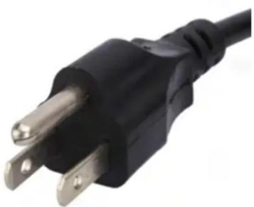
This outdoor gas cooking appliance is equipped with a three prong (grounding) plug for your protection against shock hazard and should be plugged directly into properly grounded three prong outlets. Do not cut or remove the third prong from this plug.
natural_image
Close-up of a black and silver electrical outlet plug (no text or symbols visible)Electrical equipment provided with the outdoor cooking appliance shall follow these guidelines:
- To protect against electrical shock, do not immerse cord or plugs in water or other liquid;
- Unplug from the outlet when not in use and before cleaning. Allow to cool before putting on or taking off parts;
- Do not operate any outdoor cooking gas appliance with a damaged cord, plug, or after the appliance malfunctions or has been damaged in any manner. Contact the manufacturer for repair;
- Do not let cord hang over the edge or touch hot surfaces;
- Do not use an outdoor cooking gas appliance for purposes other than intended;
- When connecting, first connect plug to the outdoor cooking gas appliance then plug appliance into outlet;
- Use only Ground Fault Interrupter (GFI) protected circuit with this outdoor cooking gas appliance;
- Never remove the grounding plug or use with an adapter of two prongs; and
- Use only extension cords with three prong grounding plugs, rated for the power of the equipment, and approved for outdoor use with a W-A marking.
This gas appliance is designed and certified for outdoor use only. Do not locate this grill under overhead combustible surfaces. When installed under overhead combustible surfaces, we recommend a ventilating hood wider than the appliance be installed with a minimum distance of 36 inches above the cooking surface.
CAUTION should be taken when grills are used near glass, vinyl siding or other temperature sensitive construction materials. In some cases, it may be necessary to increase the clearance around the grill to avoid damage to vinyl siding. Check with the manufacturer of the siding material for details.
Do not operate the grill inside a building, garage, recreation vehicle or any enclosed area. When choosing an area, consider exposure to wind, proximity to traffic paths and length of gas supply line. Keep gas supply lines as short as possible to reduce pressure drop. Keep the grill away from windy area but keep the grill in a well-ventilated area. Do not obstruct the flow of combustion and ventilation air around the grill. The supporting edges of the grill must be located level and flat. The counter should also be leveled.
CCLEARANCE TO COMBUSTIBLE CONSTRUCTION A minimum clearance of 12" from the sides and 12" from the back of the grill to adjacent vertical combustible construction must be maintained. To minimize the possibility of discoloration on adjacent construction extending above the counter-top surface due to grease and hot vapors, it is highly recommended that a clearance of 18 inches be maintained from sides and back of the grill.
CLEARANCE TO NONCOMBUSTIBLE CONSTRUCTION
A minimum clearance of 4 12 " from the back of the grill above cooking surface to non-combustible construction is required to allow the grill hood to open completely.
A minimum of 6" clearance to the sides of the grill above cooking surface to non-combustible construction is recommended. The grill can be installed directly next to non-combustible construction below the cooking surface.
Your Eagle One grill has been designed and engineered to produce intense heat that sears food quickly, locking in the foods natural moisture and flavor.
The grills burners require air for efficient burner combustion. This fresh air is pulled through a vent in the front of your grill and the intense hot air produced by the burners is expelled through a vent in the rear.
If you are using your grill in windy conditions, the wind can disrupt this important airflow.
If the grill burners are on high and the hood is closed, wind can prevent the hot air from being expelled through the rear vent – forcing heat to the control panel. This heat can make the hood handle and control knobs extremely hot. In some cases, this heat can damage important components.
To prevent overheating:
- Do not leave the hood closed with the burners on high for more than 15 minutes.
- Install your grill in a location where a prevailing wind is less likely to hit the rear of the grill. If this is not possible, install a windbreak behind your grill.
Damaged components such as wiring, control knobs, gas valves, etc. and the discoloration of the stainless steel by using the grill in windy conditions is not covered under the product warranty.

INSULATION JACKET CUT-OUT DIMENSIONS
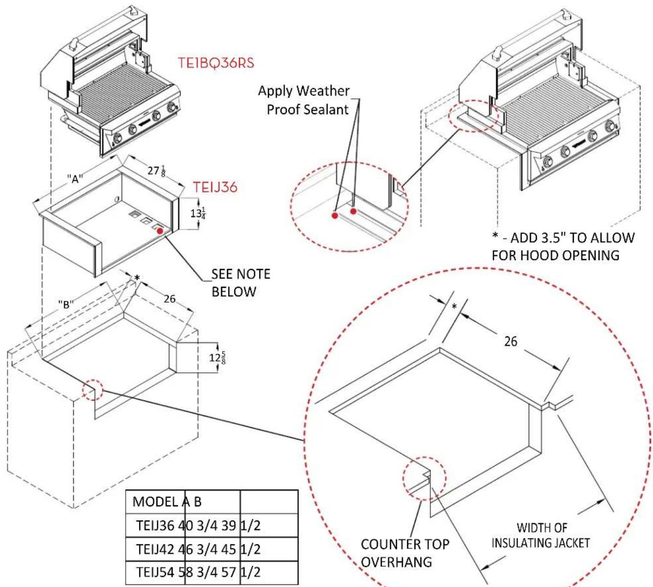
INSULATING JACKET
WARNING:
Do not build the grill under overhead combustible construction. If the grill is to be placed into combustible enclosure, an approved insulating jacket is necessary to prevent fire, property damage and bodily injury. Use only Twin Eagles insulating jacket.
NOTE:
When installing, use front right knockout to keep power cord cool. If using LP gas cylinder and insulation jacket (TEIJ), use stainless flexible hose to connect LP gas cylinder to grill Regulator.
GRILL CUT-OUT DIMENSIONS
This is for non-combustible construction. For combustible construction refer back to previous page.

OPERATING INSTRUCTIONS
- WARNING: IT IS CRITICAL THAT THE GAS BURNERS ARE PROPERLY INSTALLED WITH THEIR ORIFICES INSIDE THE BURNERS AIR SHUTTERS. If not properly installed, gas may leak outside of the burner that could lead to fire, potential damage to your grill and bodily injury. (Please refer to Page 3 for correct burner installation).
- If the unit is LP, thread the regulator on the valve of the cylinder and hand tighten until fully seated. Leak check the hose and regulator connections with a soap and water solution before operating the grill. (Reference Page 11 for leak test procedure)
- Inspect the gas supply piping or hose prior to turning the gas ON. If there is evidence of cuts, wear, or abrasion, it must be replaced prior to use. The replacement pressure regulator and hose assembly must be the type specified by the manufacturer. The pressure regulator and hose assembly supplied with the units must be used.
• Always keep your face and body as far away as possible when lighting.
- Open the grill hood completely. Do not attempt to light the grill with the hood closed.
- Open the gas supply shut-off valve.
- Push in the knob and verify that the hot surface igniter glows. The hot surface igniter's are located inside the flashtubes above the U-burners. If the igniter does not glow, verify for proper power supply. (Reference Page 12 for electrical requirements).
- After the glowing is verified, hold the knob pushed-in for 5 seconds then turn the knob counter clockwise so that all the bezel LEDS are lit. Continue to hold the knob pushed in for 5 seconds until you see or hear a flame. Then release the knob.
CAUTION: If ignition does not take place within 5 seconds, turn knob to the OFF position, wait for five minutes and repeat step 4.
- Once ignited close the hood to allow the grill to preheat until the Temp. Track displays the desired grilling temperature range.

natural_image
Close-up of a white stainless steel appliance with two circular control knobs and a brand logo (no readable text or symbols beyond branding)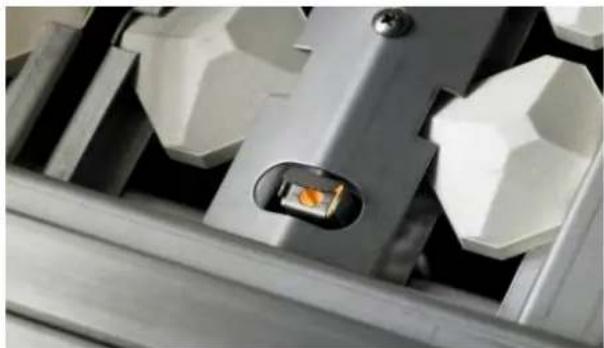
natural_image
Close-up of a mechanical component with a highlighted orange square and metallic base (no visible text or symbols)ATTENTION:
On initial use, light the grill and let it run for approximately 15-20 minutes to burn off any residue from the factory
USING THE GRILL
- Check to be certain that the drip pan is in place and pushed all the way back into the grill.
-
Light the grill burners using the instructions above.
-
Turn the control knobs to HI and allow the grill to preheat for 15 minutes or until desired temperature is displayed on the Temp Track. The hood is to be closed during this preheat period.
- Place the food on the grill and cook to the desired temperature doneness. Adjust heat setting, if necessary. The control knob may be set to any position between HI and LO.
- Allow grill to cool and clean the drip pan after each use.
TO LIGHT THE ROTIS BURNERS
- Open the grill hood completely. Do not attempt to light the grill with the hood closed.
- Open the gas supply shut-off valve.
- Push in the knob and verify that the hot surface igniter glows. The hot surface igniter's are located on the rear panel next to the rotisserie burner. If the igniter does not glow, verify for proper power supply. (Reference Page 10 for electrical requirements).
- After the glowing is verified, hold the knob pushed-in for 5 seconds then turn the knob counter clockwise so that all the bezel LEDS are lit. Continue to hold the knob pushed in for 5 seconds until you see or hear a flame. Then release the knob.
CAUTION: If ignition does not take place within 5 seconds, turn knob to the OFF position, wait for five minutes and repeat step 4.
- Once ignited close the hood to allow the grill to preheat until the Temp. Track displays the desired grilling temperature range.
USING THE ROTISSERIE
- Insert the food on the middle of the spit rod and then secure it with the meat holders on both ends by tightening the thumb screws on the meat forks. If multiple pieces of food will be cooked at the same time, make sure the load is evenly balanced on the spit rod. Proper weight balancing will ensure evenness of cooking and prolong the life of the rotisserie motor.
- Insert the spit rod in the rotisserie at desired cooking position. For large loads use lower position and for smaller loads use the upper position. You may need to remove the cooking grates to create clearance for bigger loads of food.
- Always use the basting pan beneath the food to catch drippings and prevent them from falling on the burners and briquette trays.
- Locate switch marked with the fork symbol (☐)
- Press in switch to start the rotisserie.
- Locate the rotisserie knob(s) with the fork symbol (☐)
- Hold the knob pushed-in for 5 seconds then turn the knob counter clockwise to the biggest flame marking on the bezel. Once you see or hear a flame you can release the knob.
- NOTE: The Rotisserie Igniter will remain lit during use.
- Once lit, close the hood for preheat.

natural_image
Close-up of a stainless steel industrial machine with a cylindrical component inserted, showing internal structure and ventilation slots (no text or symbols visible)CAUTION: If ignition does not take place within 5 seconds, turn knob to the OFF position, wait for five minutes and repeat step 7.
- Once cooking is completed, shut-off the rotisserie burner and main valve.
WARNING:
When using the rotisserie always keep the front hood closed except when basting or checking the meat for cooking completion. It is recommended to use a meat thermometer to check if the food is completely cooked.
CAUTION: In sunny or heavy light environments, the flame from the infrared rotisserie burner may be difficult to see and verify complete ignition.
OPERATING INSTRUCTIONS - cont.
MATCH/BBQ LIGHTER LIGHTING INSTRUCTIONS
If there is no electrical power supply available or if hot surface igniter will not light the U-Burner(s) or I.R. burner(s), the grill may be lit manually using a lighted long match, taper or BBQ lighter.
- For the Rotisserie: insert a BBQ lighter through the match lite hole above the I.R. Glass assembly. For the U-burner: insert BBQ lighter through the match lite opening at the front of the grate, angled towards the burner.
- Push and turn the knob counter-clockwise till the bezel lights are fully lit. Hold the knob pushed in for 5 seconds. Once you see or hear a flame, you can remove the igniter.
Important: If burner fails to light within 5 seconds, turn off gas and wait 5 minutes before repeating the process.

USING THE SEAR BURNER
Searing steaks and other meats with infrared sear burner at the beginning of the grilling cycle helps lock in juices and flavor. Sear the meats quickly with the front hood open (2 min each side), followed by regular grilling over the Main Burner.
CAUTION:
Never allow liquids to come in contact with the Infrared Sear Zone burner since it could cause damage to the ceramic tiles. DO NOT place briquette tray or smoker box over the sear burner. This will block the infrared heat and will damage the tray.
The Eagle One is equipped with two interior Halogen lights on the TE1BQ36/TE1BQ42, and three interior Halogen lights on the TE1BQ54. The interior Halogen lights power off automatically when the hood is closed.
- Push the switch located on the front panel to turn ON/OFF interior Halogen lights, the mood light, and bezel back lights.
The Twin Eagles sealed smoker box can hold dry wood chips or liquids for hickory, mesquite or your favorite wood chips to give meat a smoky flavor.
- Remove a grate.
- Remove a half size briquette tray where there is no flashtube and replace it with the smoker box.
- Add your favorite soaked wood chips.
- Wait for the chips to start smoking and you are ready to start grilling.

IMPORTANT Stainless Steel & General Product Care
To keep your Twin Eagles products free of surface corrosion and in good working order, it is important to take additional precautions under certain conditions.
If your Twin Eagles products are located in corrosive conditions, such as:
- A coastal environment where corrosive salty air is present.
- Near a swimming pool, hot tub or water feature with exposure to corrosive pool chemicals and/or chlorinated water.
- Areas where muriatic acid (hydrochloric acid) or other corrosive cleaning solutions are used to clean concrete and masonry.
- Areas where corrosive masonry dust and debris are created by cutting stone or mixing cements.
These conditions can create a highly corrosive environment that will cause the corrosion resistant type 304 stainless steel to develop surface oxidation, corrosion or rust.
- Twin Eagles products have been tested in saline solutions, highly chlorinated solutions and have been tested against exposure to highly acidic foods. The test results proved the type 304 stainless steel can withstand exposure over prolonged periods of time. However, the conditions outlined above, along with neglect, can lead to surface corrosion or rust.
- It is recommended that your Twin Eagles products be kept dry and covered when not in use. This is even more important when long-term storage is intended.
- Do not allow food particles or grease to be left inside your Twin Eagles products. These can attract rodents, which are unsanitary and are likely to cause physical damage by chewing on the wiring, which can cause permanent damage to the electrical components.
- If you are located along the coast or in the desert, wind driven sand is extremely abrasive and can pit and scratch the stainless steel. Keep your Twin Eagles products covered when not in use.
With routine cleaning, maintenance and awareness of the conditions outlined above, you can enjoy many years of service from your Twin Eagles products.
In the event that surface corrosion has developed on the stainless steel, it is typically not the stainless steel that is corroding but corrosive particles that have been deposited on the surface.
- Twin Eagles grills are made of all welded stainless steel. It is non-rusting and non-magnetic. Never clean the stainless steel when it is hot. After the initial grilling use, certain areas of the grill may discolor. This is a normal discoloration caused by the intense heat given off by the burners.
- Specks of grease can gather on the surface of the stainless steel and get baked-on. These can be removed by using a mild abrasive pad with a stainless-steel cleaner. Use the mildest cleaner and always scrub in the direction of the grain. Do not use steel wool to clean the grill.
Do not use abrasives on the polished highlights. Be extra careful when cleaning around the highlights. Metal polisher or mild chrome cleaner can be used to bring back the luster on highlights. To touch-up minor scratches in the stainless steel, sand the affected surface very lightly, with 100-dry grit emery sandpaper in the direction of the grain.
CLEANING & MAINTENANCE - cont.
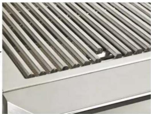
GRATES
The easiest way to clean the grates is to scrub them with a barbecue brush immediately after cooking is completed and the flame is turned off.
Wear a barbecue mitt to protect your hands from the heat and steam. Dip a barbecue brush in tap water and scrub the hot grill. Dip the brush frequently in tap water. Steam, created as water comes in contact with the hot grill, helps loosen food particles stuck in the grill. These food particles will either get burned by the briquettes or fall into the cleaning pan. Cleaning of the grill would be longer and more difficult if the grill racks are allowed to cool before cleaning. When cleaning the grates make sure not to hit the rotis-serie glass.
natural_image
Close-up of a metallic roof with parallel slats and a small hole, no visible text or symbolsCERAMIC BRIQUETTE TRAY
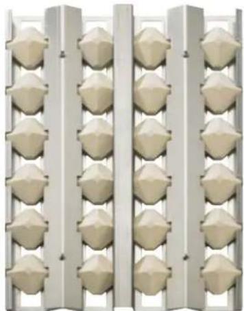
It is not necessary to remove and clean the briquettes from the tray after every grilling. They burn
themselves clean during the next cooking operation. If desired, you can burn them clean by lighting the grill and letting it burn on high for about 30 minutes with the briquette tray upside down. Periodically, the briquette trays need to be cleaned. Remove them from the grill, shake loose the debris and wipe the trays clean. Do not handle a hot briquette tray.
natural_image
Repeating geometric pattern of beige 3D spheres arranged in vertical columns (no text or symbols)WARNING
DO NOT place briquette trays over the infrared sear zone burner. This will block the infrared heat and will cause damage to the tray.
REPLACING THE BRIQUETTES
- Remove the screws that hold the trim.
- Remove the old briquettes and place the new briquettes on the same location as the old ones.
-
Replace screws and tighten.
-
Place the trim with the flash-tube-hole on the trim on the same side as the flash-tube-hole on the tray.
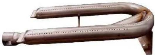
BURNERS
Burners are made of heavy gauge stainless steel and can be soaked in water and cleaned with a wire brush. Check every port hole for clogs. Use a wire pin to clean out clogged ports. Make sure the burner is dry before installing it back into the grill.
natural_image
Metallic curved pipe or duct component with perforated end, no visible text or symbolsCLEANING & MAINTENANCE - cont.
INFRARED SEAR BURNER
The infrared burner has stainless housing and a protective screen. The protective screen helps reflect heat up to the cooking surface and also catches any food particles from landing on the ceramic burner. At the searing temperatures that the burner reaches all food particles will be burned off so the only maintenance required is cleaning the protective screen and checking for any objects that may be trapped.
DRIP PAN
The drip pan collects grease, liquid and fallen food particles. Allow the pan and its contents to cool before cleaning. Slide the pan out and wipe it clean. Make sure the drip pan is fully inserted back into the grill. It is highly recommended to clean the pan after every use to avoid any possibility of a grease fire. DO NOT use the grill without the drip pan pushed all the way to the back of the grill unit.

natural_image
Close-up of a metallic heating element with vertical slats and warm-colored insulation (no text or symbols visible)
natural_image
Close-up of stainless steel kitchen cabinets with gridded metal surfaces (no visible text or symbols)REPLACING THE INTERIOR BULBS
- Disconnect grill from power source.
- Gently pop the lens cover out.
- Remove the old light bulb by pulling it straight out of the socket without twisting the light bulb.
- Wearing plastic gloves, insert the new light bulb into the socket. DO NOT touch bulb with bare hands as the oil and dirt will shorten bulb life. (Bulb is small with two prongs, 12V/10W, do not handle without gloves)
WARNING: Do not touch the interior halogen lights. They may be hot and can cause serious burns.
SMOKER BOX
The smoker box is a component that can be easily removed from the grill for cleaning. The lid easily comes off for easy cleaning.

natural_image
Open metallic box containing dried, sliced dried ingredients (no text or symbols visible)SPIDER AND INSECT WARNING
Spiders and other insects can nest in the burners of this and any other grills, which causes the gas to flow from the front of the burner. This dangerous “condition” can cause a fire behind the valve panel, damaging the grill and making the grill unsafe to operate. Inspect the burners once a year or if the grill has not been used for more than one month or if any of the following conditions occur:
- The smell of gas in conjunction with the burner flames appearing yellow.
- The grill does not reach temperature.
- The grill heats unevenly.
- The burners make popping noises.
EAGLE ONE EXPLODED VIEW

REPLACEMENT PARTS LIST
| ITEM NO. | TE PART NUMBER | DESCRIPTION | TE1BQ 36RSN | TE1BQ 36RSL | TE1BQ 42RSN | TE1BQ 42RSL | TE1BQ 54RSN | TE1BQ 54RSL |
| 1 S27211-36WY 36 FRONT | HOOD WELDED ASSEMBLY 1 1 ---- | |||||||
| 2 S27211-42WY 42 FRONT | HOOD WELDED ASSEMBLY -- 1 1 -- | |||||||
| 3 S27211-54WY 54 FRONT | HOOD WELDED ASSEMBLY ---- 1 1 | |||||||
| 4 S12368-36 HOOD HANDLE (∅1.25" X 27.85") 1 1 ---- | ||||||||
| 5 S12368-42 HOOD HANDLE (∅1.25" X 33.85") -- 1 1 -- | ||||||||
| 6 S12368-54 HOOD HANDLE (∅1.25" X 45.85") ---- 1 1 | ||||||||
| 7 S133284 HANDLE END CAP 2 2 2 2 2 2 | ||||||||
| 8 S14226 HOOD SPRING 2 2 2 2 2 | ||||||||
| 9 S14340 HOOD SLEEVE 2 2 2 2 2 | ||||||||
| 10 | S14303 | .25 x 1.75 SS HEX HEAD HOOD SCREW | 2 | 2 | 2 | 2 | 2 | 2 |
| 11 | S27216-36Y | 36 REAR HOOD ASSEMBLY | 1 | 1 | - | - | - | - |
| 12 | S27216-42Y | 42 REAR HOOD ASSEMBLY | - | - | 1 | 1 | - | - |
| 13 | S27216-54Y | 54 REAR HOOD ASSEMBLY | - | - | - | - | 1 | 1 |
| 14 | S27234-36 | 36 REAR HOOD COVER | 1 | 1 | - | - | - | - |
| 15 | S27234-42 | 42 REAR HOOD COVER | - | - | 1 | 1 | - | - |
| 16 | S27234-54 | 54 REAR HOOD COVER | - | - | - | - | 1 | 1 |
| 17 | S27235-36 | 36 FLUE COVER | 1 | 1 | - | - | - | - |
| 18 | S27235-42 | 42 FLUE COVER | - | - | 1 | 1 | - | - |
| 19 | S27235-54 | 54 FLUE COVER | - | - | - | - | 1 | 1 |
| 20 | S13411 | INFRARED BURNER - SMALL | 1 | 1 | - | - | 2 | 2 |
| 21 | S13412 | INFRARED BURNER - LARGE | - | - | 1 | 1 | - | - |
| 22 | S16322 | ROTIS IGNITER | 1 | 1 | 1 | 1 | 1 | 1 |
| 23 | S16423 | RIGHT HAND ROTIS IGNITER | - | - | - | - | 1 | 1 |
| 24 | S27219-L | I.R. HOOD - LH | 1 | 1 | 1 | 1 | 1 | 1 |
| 25 | S27219-R | I.R. HOOD - RH | - | - | - | - | 1 | 1 |
| 26 | S12696 | COMPRESSION, TUBE FITTING, 3/8 CC X 3/8 CC | 1 | 1 | 1 | 1 | 3 | 3 |
| 27 | S12421 | FLEX TUBE, 3/8 CC X 40" | 1 | 1 | 1 | 1 | 2 | 2 |
| 28 | S12640 | ELBOW | 1 | 1 | 1 | 1 | 2 | 2 |
| 29 | S15108-48 | ORIFICE #48, NG | 1 | - | - | - | 2 | - |
| 30 | S15108-55 | ORIFICE #55, LP | - | 1 | - | - | - | 2 |
| 31 | S15108-41 | ORIFICE #41, NG | - | - | 1 | - | - | - |
| 32 | S15108-53 | ORIFICE #53, LP | - | - | - | 1 | - | - |
| 33 | S14194 | SPRING STANDOFF | 2 | 2 | 2 | 2 | 2 | 2 |
| 34 | S16240 | HALOGEN LIGHT BODY | 2 | 2 | 2 | 2 | 3 | 3 |
| 35 | S16241 | COVER LENS | 2 | 2 | 2 | 2 | 3 | 3 |
| 36 | S16191 | BULB, HALOGEN LIGHT | 2 | 2 | 2 | 2 | 3 | 3 |
| 37 | S26310 | ROTIS PLATE SPACER | 4 | 4 | 4 | 4 | 4 | 4 |
| 38 | S14420 | ROLLER BEARING | 4 | 4 | 4 | 4 | 4 | 4 |
| 39 | S27236 | WARMING RACK BRACKET | 2 | 2 | 2 | 2 | 2 | 2 |
| 40 | S26308Y | SPROCKET ASSEMBLY | 1 | 1 | 1 | 1 | 1 | 1 |
| 41 | S27232 | SPROCKET COVER | 1 | 1 | 1 | 1 | 1 | 1 |
| 42 | S27225-36Y | INFRARED GLASS ASSEMBLY, 36 | 1 | 1 | - | - | - | - |
| 43 | S27225-42Y | INFRARED GLASS ASSEMBLY, 42 | - | - | 1 | 1 | - | - |
| 44 | S27225-54Y | INFRARED GLASS ASSEMBLY, 54 | - | - | - | - | 1 | 1 |
REPLACEMENT PARTS LIST - cont.
| ITEM NO. | TE PART NUMBER | DESCRIPTION | TE1BQ 36RSN | TE1BQ 36RSL | TE1BQ 42RSN | TE1BQ 42RSL | TE1BQ 54RSN | TE1BQ 54RSL |
| 45 S14 | 532-36 INFRARED GLASS, 36 1 1 --- | |||||||
| 46 S14 | 532-42 INFRARED GLASS, 42 -- 1 1 -- | |||||||
| 47 S14 | 532-54 INFRARED GLASS, 54 ---- 1 1 | |||||||
| 48 S27 | 223-36 GLASS GASKET, 36 2 2 ---- | |||||||
| 49 S27 | 223-42 GLASS GASKET, 42 -- 2 2 -- | |||||||
| 50 S27 | 223-54 GLASS GASKET, 54 ---- 2 2 | |||||||
| 51 S27 | 227-36 INFRARED GLASS BOTTOM TRIM ASSEMBLY, 36 1 1 ---- | |||||||
| 52 S27 | 227-42 INFRARED GLASS BOTTOM TRIM ASSEMBLY, 42 -- 1 1 -- | |||||||
| 53 S27 | 227-54 INFRARED GLASS BOTTOM TRIM ASSEMBLY, 54 ---- 1 1 | |||||||
| 54 | S27225-36WY | INFRARED GLASS TOP TRIM WELDED ASSEMBLY, 36 | 1 | 1 | - | - | - | - |
| 55 | S27225-42WY | INFRARED GLASS TOP TRIM WELDED ASSEMBLY, 42 | - | - | 1 | 1 | - | - |
| 56 | S27225-54WY | INFRARED GLASS TOP TRIM WELDED ASSEMBLY, 54 | - | - | - | - | 1 | 1 |
| 57 | S27229 | VERTICAL GLASS CHANNEL | 2 | 2 | 2 | 2 | 3 | 3 |
| 58 S27 | 200-36WY 36 FRONT | PANEL WELDED ASSEMBLY 1 1 ---- | ||||||
| 59 S27 | 200-42WY 42 FRONT | PANEL WELDED ASSEMBLY -- 1 1 ---- | ||||||
| 60 S27 | 200-54WY 54 FRONT | PANEL WELDED ASSEMBLY ---- 1 1 | ||||||
| 61 S27 | 202-36WY 36 FRONT | INNER PANEL WELDED ASSEMBLY 1 1 ---- | ||||||
| 62 S27 | 202-42WY 42 FRONT | INNER PANEL WELDED ASSEMBLY -- 1 1 ---- | ||||||
| 63 S27 | 202-54WY 54 FRONT | INNER PANEL WELDED ASSEMBLY ---- 1 1 | ||||||
| 64 S27 | 205-36 36 ELBOW PANEL | 1 1 ---- | ||||||
| 65 S27 | 205-42 42 ELBOW PANEL | -- 1 1 ---- | ||||||
| 66 S27 | 205-54 54 EBOW PANEL | ---- 1 1 | ||||||
| 67 | S12764-36Y | 36 MANIFOLD ASSEMBLY | 1 | 1 | - | - | - | - |
| 68 | S12764-42Y | 42 MANIFOLD ASSEMBLY | - | - | 1 | 1 | - | - |
| 69 | S12764-54Y | 54 MANIFOLD ASSEMBLY | - | - | - | - | 1 | 1 |
| 70 S13 | 228-36 MOOD LIGHT, 36 | 1 1 ---- | ||||||
| 71 S13 | 228-42 MOOD LIGHT, 42 | -- 1 1 ---- | ||||||
| 72 S13 | 228-54 MOOD LIGHT, 54 | ---- 1 1 | ||||||
| 73 | S27204 | TEMP STRIP BRACKET | 1 | 1 | 1 | 1 | 1 | 1 |
| 74 | S16028 | 36 / 42 TEMP STRIP | 1 | 1 | 1 | 1 | - | - |
| 75 S16 | 034 54 | TEMP STRIP | ---- 1 1 | |||||
| 76 | S16196 | 12V ILLUMINATED SWITCH | 1 | 1 | 1 | 1 | 1 | 1 |
| 77 | S16365 | 110V ILLUMINATED SWITCH | 1 | 1 | 1 | 1 | 1 | 1 |
| 78 | S13273 | LIGHT BEZEL ASSEMBLY | 4 | 4 | 4 | 4 | 6 | 6 |
| 79 | S13279 | BEZEL O-RING | 4 | 4 | 4 | 4 | 6 | 6 |
| 80 | S13224 | BEZEL LENS | 4 | 4 | 4 | 4 | 6 | 6 |
| 81 | S13283 | KNOB ASSEMBLY | 4 | 4 | 4 | 4 | 6 | 6 |
| 82 | S13287 | EAGLE ONE EMBLEM | 1 | 1 | 1 | 1 | 1 | 1 |
| 83 | S16020 | CONTROL MODULE | 1 | 1 | 1 | 1 | 1 | 1 |
| 84 | S16042Y | RESET SWITCH | 1 | 1 | 1 | 1 | 1 | 1 |
| 85 | S16385 | MEANWELL TRANSFORMER (LPVL-150-12) | 1 | 1 | 1 | 1 | 1 | 1 |
| 86 | S16426 | MEANWELL POWER SUPPLY ASSY. (LPV-20-5 15W 5V) | 1 | 1 | 1 | 1 | 1 | 1 |
| 87 | S12603 | ELBOW MIXER | 3 | 3 | 3 | 3 | 4 | 4 |
| 88 | S15110-41 | ORIFICE, #41, 1/8 NPT | 3 | - | 3 | - | 4 | - |
| 89 S15 | 110-53 ORIFICE, #53 | 1/8 NPT - 3 - 3 - 4 | ||||||
| 90 S15 | 152 STRAIGHT VALVE | W/ MICROSWITCH 3 3 3 4 4 | ||||||
| 91 S15 | 153 STRAIGHT VALVE | W/ MICROSWITCH & CONSTANT ON 1 1 1 1 2 2 | ||||||
| 92 S12 | 601 ELBOW 4 4 4 4 6 | 6 | ||||||
| 93 S16 | 386 TERMINAL BLOCK | 1 1 1 1 1 1 | ||||||
| 94 S19 | 195 TERMINAL BLOCK | K LABEL 1 1 1 1 1 1 | ||||||
| 95 S26 | 372 TERMINAL BLOCK | K COVER 1 1 1 1 1 1 | ||||||
| 96 | S27242-36 | 36 FRONT AIR BAFFLE | 1 | 1 | - | - | - | - |
| 97 | S27242-42 | 42 FRONT AIR BAFFLE | - | - | 1 | 1 | - | - |
| 98 | S27242-54 | 54 FRONT AIR BAFFLE | - | - | - | - | 1 | 1 |
| 99 S16 | 031 TEMP PROBE | 3 3 3 3 4 4 | ||||||
| 100 | S26344 IGNITION COVER | 3 3 3 3 4 4 | ||||||
| 101 | S26319-36 | 36 DRIP PAN | 1 | 1 | - | - | - | - |
| 102 | S26319-42 | 42 DRIP PAN | - | - | 1 | 1 | - | - |
| 103 | S26319-54 | 54 DRIP PAN | - | - | - | - | 1 | 1 |
| 104 | S27208-36WY | 36 DRIP PAN HANDLE WELDED ASSEMBLY | 1 | 1 | - | - | - | - |
| 105 | S27208-42WY | 42 DRIP PAN HANDLE WELDED ASSEMBLY | - | - | 1 | 1 | - | - |
| 106 | S27208-54WY | 54 DRIP PAN HANDLE WELDED ASSEMBLY | - | - | - | - | 1 | 1 |
| 107 | S13928-36 | SPIT ROD, 36 | 1 | 1 | - | - | - | - |
| 108 | S13928-42 | SPIT ROD, 42 | - | - | 1 | 1 | - | - |
| 109 | S13928-54 | SPIT ROD, 54 | - | - | - | - | 1 | 1 |
| 110 | S13865 | MEAT HOLDER FORKS (PAIR) | 1 | 1 | 1 | 1 | 1 | 1 |
| 111 | S16321 IGNITER | 3 3 3 3 4 4 | ||||||
| 112 | S27377 IGNITER SHIELD | 3 3 3 3 4 4 | ||||||
| 113 | S27243-36 | 36 BOTTOM VALVE PANEL | 1 | 1 | - | - | - | - |
| 114 | S27243-42 | 42 BOTTOM VALVE PANEL | - | - | 1 | 1 | - | - |
| 115 | S27243-54 | 54 BOTTOM VALVE PANEL | - | - | - | - | 1 | 1 |
| 116 | S16112 STRAIN RELIEF | 1 1 1 1 1 | ||||||
| 117 | S16111 ELECTRICAL CORD | 1 1 1 1 1 | ||||||
| 118 | S16194 HOOD SWITCH | 1 1 1 1 1 | ||||||
| 119 | S12112 | SWITCH ROD | 1 | 1 | 1 | 1 | 1 | 1 |
| 120 | S14232 | RETENTION RING | 1 | 1 | 1 | 1 | 1 | 1 |
| 121 | S21756 | HOOD SWITCH BRACKET | 1 | 1 | 1 | 1 | 1 | 1 |
| 122 | S12618 .5 NIPPLE | 2 2 2 2 2 2 | ||||||
| 123 | S12602 BRASS COUPLING | 1 1 1 1 1 | ||||||
| 124 | S15303 | NG REGULATOR | 1 | 1 | 1 | 1 | 1 | 1 |
| 125 | S26713 REGULATOR BRACKET 1 1 1 1 1 | |||||||
| 126 | S15302-GR150 | LP REGULATOR W/ HOSE | - | 1 | - | 1 | - | 1 |
| 127 | S16366 | ROTIS MOTOR | 1 | 1 | 1 | 1 | 1 | 1 |
| 128 | S26349 ROTIS MOTOR HOUSING 1 1 1 1 1 | |||||||
| 129 | S26351 | ROTIS HOUSING COVER | 1 | 1 | 1 | 1 | 1 | 1 |
| 130 | S13932 CHAIN | 1 1 1 1 1 | ||||||
| 131 | S26352 CHAIN GUARD | 1 1 1 1 1 | ||||||
| 132 | S13301 | U6-BURNER | - | - | 2 | 2 | 3 | 3 |
REPLACEMENT PARTS LIST - cont.
| ITEM NO. | TE PART NUMBER | DESCRIPTION | TE1BQ 36RSN | TE1BQ 36RSL | TE1BQ 42RSN | TE1BQ 42RSL | TE1BQ 54RSN | TE1BQ 54RSL |
| 133 S1 | 350 U5-BURNER 2 2 | ---- | ||||||
| 134 S1 | 345 SEAR BURNER ASSEMBLY 1 1 1 1 1 1 | |||||||
| 135 S1 | 144 SEAR BURNER MESH SCREEN 1 1 1 1 1 1 | |||||||
| 136 S2 | 345 BURNER DOOR 2 2 2 2 3 3 | |||||||
| 137 S2 | 78WY U-BURNER FLASHTUBE 2 2 2 2 3 3 | |||||||
| 138 S2 | 780WY SEAR ZONE FLASH TUBE 1 1 1 1 1 1 | |||||||
| 139 S2 | 743 DIVIDER 2 2 2 2 3 3 | |||||||
| 140 S1 | 954-36 36 WARMING RACK 1 1 ---- | |||||||
| 141 S1 | 954-42 42 WARMING RACK -- 1 1 - | |||||||
| 142 S1 | 954-54 54 WARMING RACK ---- 1 1 | |||||||
| 143 S1 | 951 HEX GRATES, 10.5625 3 3 ---- | |||||||
| 144 S1 | 952 HEX GRATES, 12 -- 1 1 2 2 | |||||||
| 145 S1 | 953 HEX GRATES, 12.8125 -- 2 2 2 2 | |||||||
| 146 | S27387Y | 5" BRIQUETTE TRAY ASSEMBLY | 2 | 2 | - | - | - | - |
| 147 | S27389Y | 6" BRIQUETTE TRAY ASSEMBLY | - | - | 2 | 2 | 2 | 2 |
| 148 | S27386Y | 10" BRIQUETTE TRAY ASSEMBLY | 1 | 1 | - | - | - | - |
| 149 | S27388Y | 12" BRIQUETTE TRAY ASSEMBLY | - | - | 1 | 1 | 2 | 2 |
| 150 | S2737Y | 36 SMOKER BOX ASSEMBLY | 1 | 1 | - | - | - | - |
| 151 | S2735Y | 42 / 54 SMOKER BOX ASSEMBLY | - | - | 1 | 1 | 1 | 1 |
| 152 S1 | 803 BASTING PAN | 1 1 1 1 2 2 | ||||||
| 153 S1 | 420 .375 X 9 FLEX TUBE | 1 1 1 1 1 1 | ||||||
| 154 S1 | 4128 RUBBER BUMPER | 4 4 4 4 4 4 | ||||||
| 155 S1 | 407 .375 X 7.5 FLEX TUBE | 4 4 4 4 6 6 | ||||||
| 156 | S27237-36WY | 36 FIREBOX WELDED ASSEMBLY | 1 | 1 | - | - | - | - |
| 157 | S27237-42WY | 42 FIREBOX WELDED ASSEMBLY | - | - | 1 | 1 | - | - |
| 158 | S27237-54WY | 54 FIREBOX WELDED ASSEMBLY | - | - | - | - | 1 | 1 |
| 159 S2 | 7394 ACCESS COVER | 1 1 1 1 2 2 | ||||||
| PARTS NOT SHOWN | ||||||||
| 159 S1 | 6022 WIRE HARNESS | 13IN. SWITCH TO MASTER CONTROL 2 2 2 2 1 1 | ||||||
| 160 S1 | 6023 WIRE HARNESS | 14IN. KNOB TO MASTER CONTROL 1 1 1 1 -- | ||||||
| 161 S1 | 6024 WIRE HARNESS | 20IN. KNOB TO MASTER CONTROL ---- 2 2 | ||||||
| 162 S1 | 6025 WIRE HARNESS | 26IN. KNOB TO MASTER CONTROL 2 2 2 2 4 4 | ||||||
| 163 S1 | 6026 WIRE HARNESS | 33IN. KNOB TO MASTER CONTROL 1 1 1 1 2 2 | ||||||
| 164 S1 | 6027 WIRE HARNESS | 34IN. SWITCH TO MASTER CONTROL 2 2 2 2 3 3 | ||||||
| 165 S1 | 6037 WIRE HARNESS | ROTISSERIE 1 1 1 1 1 1 | ||||||
| 166 S1 | 6038 WIRE HARNESS | FRONT PANEL (36, 42) 1 1 1 1 -- | ||||||
| 167 S1 | 6039 WIRE HARNESS | FRONT PANEL (54) ---- 1 1 | ||||||

flowchart
graph TD
    subgraph Top_Lower_Circuit
        A["MOOD LIGHT SW CONN RHUHS"] --> B["R"]
        B --> C["C"]
        C --> D["NC"]
        D --> E["K"]
        E --> F["ML"]
        F --> G["SBE"]
        G --> H["12V"]
        H --> I["HOOD SW"]
        I --> J["SLEEVE"]
        J --> K["HOOΩ"]
        K --> L["ML"]
        L --> M["12C"]
        M --> N["ML"]
        N --> O["12VDC"]
        O --> P["OUT"]
        P --> Q["LINE NEUT"]
        Q --> R["K"]
        R --> S["C"]
        S --> T["N"]
        T --> U["FEED"]
        U --> V["NO L"]
        V --> W["N 12VDC IN OUT"]
        W --> X["SEE TABLE"]
        X --> Y["SEE TABLE"]
        Y --> Z["T4 T3 T2 T1 T4"]
        Y --> AA["T4 T3 T2 T1 T4"]
        Y --> AB["T4 T3 T2 T1 T4"]
    end

    subgraph Bottom_Lower_Circuit
        AC["36" GRILL KNOB AND THERMOCOUPLE LAYOUT"] --> AD["T1 T3 T4 R1 3 ○ ○ ○ 4"]
        AE["42" GRILL KNOB AND THERMOCOUPLE LAYOUT"] --> AF["T1 T2 T4 R1 2 ○ ○ ○ 4"]
        AG["54" GRILL KNOB AND THERMOCOUPLE LAYOUT"] --> AH["T1T2 T3 R1 28 ○ ○ ○ 4 R2"]
    end

    style Top_Lower_Circuit fill:#f9f,stroke:#333
    style Bottom_Lower_Circuit fill:#ccf,stroke:#333
    style Bottom_Lower_Circuit fill:#cfc,stroke:#333
    style Bottom_Lower_Circuit fill:#fcc,stroke:#333
    style Bottom_Lower_Circuit fill:#ffc,stroke:#333
    style Bottom_Lower_Circuit fill:#fcf,stroke:#333
    style Bottom_Lower_Circuit fill:#cff,stroke:#333
    style Bottom_Lower_Circuit fill:#ffc,stroke:#333
    style Bottom_Lower_Circuit fill:#cfc,stroke:#333
    style Bottom_Lower_Circuit fill:#fcc,stroke:#333
    style Bottom_Lower_Circuit fill:#ffc,stroke:#333
    style Bottom_Lower_Circuit fill:#cfc,stroke:#333
    style Bottom_Lower_Circuit fill:#fcc,stroke:#333
    style Bottom_Lower_Circuit fill:#ffc,stroke:#333
    style Bottom_Lower_Circuit fill:#cfc,stroke:#333
    style Bottom_Lower_Bus_1(Bus) fill:#fff,stroke:#000
    style Bottom_Lower_Bus_2(Bus) fill:#fff,stroke:#000
    style Bottom_Lower_Bus_3(Bus) fill:#fff,stroke:#000
    style Bottom_Lower_Bus_4(Bus) fill:#fff,stroke:#000
    style Bottom_Lower_Bus_5(Bus) fill:#fff,stroke:#000
    style Bottom_Lower_Bus_6(Bus) fill:#fff,stroke:#000
    style Bottom_Lower_Bus_7(Bus) fill:#fff,stroke:#000
    style Bottom_Lower_Bus_8(Bus) fill:#fff,stroke:#000
    style Bottom_Lower_Bus_9(Bus) fill:#fff,stroke:#000
    style Bottom_Lower_Bus_10(Bus) fill:#fff,stroke:#000
    style Bottom_Lower_Bus_11(Bus) fill:#fff,stroke:#000
    style Bottom_Lower_Bus_12(Bus) fill:#fff,stroke:#000
    style Bottom_Lower_Bus_13(Bus) fill:#fff,stroke:#000
    style Bottom_Lower_Bus_14(Bus) fill:#fff,stroke:#000
    style Bottom_Lower_Bus_15(Bus) fill:#fff,stroke:#000
    style Bottom_Lower_Bus_16(Bus) fill:#fff,stroke:#000
    style Bottom_Lower_Bus_17(Bus) fill:#fff,stroke:#000
    style Bottom_Lower_Bus_18(Bus) fill:#fff,stroke:#000
    style Bottom_Lower_Bus_19(Bus) fill:#fff,stroke:#000
    style Bottom_Lower_Bus_20(Bus) fill:#fff,stroke:#000
    style Bottom_Lower_Bus_21(Bus) fill:#fff,stroke:#000
    style Bottom_Lower_Bus_22(Bus) fill:#fff,stroke:#000
    style Bottom_Lower_Bus_23(Bus) fill:#fff,stroke:#000
    style Bottom_Lower_Bus_24(Bus) fill:#fff,stroke:#000
    style Bottom_Lower_Bus_25(Bus) fill:#fff,stroke:#000
    style Bottom_Lower_Bus_26(Bus) fill:#fff,stroke:#000
    style Bottom_Lower_Bus_27(Bus) fill:#fff,stroke:#000
    style Bottom_Lower_Bus_28(Bus) fill:#fff,stroke:#000
    style Bottom_Lower_Bus_29(Bus) fill:#fff,stroke:#000
    style Bottom_Lower_Bus_30(Bus) fill:#fff,stroke:#000
    style Bottom_Lower_Bus_31(Bus) fill:#fff,stroke:#000
    style Bottom_Lower_Bus_32(Bus) fill:#fff,stroke:#000
    style Bottom_Lower_Bus_33(Bus) fill:#fff,stroke:#000
    style Bottom_Lower_Bus_34(Bus) fill:#fff,stroke:#000
    style Bottom_Lower_Bus_35(Bus) fill:#fff,stroke:#000
    style Bottom_Lower_Bus_36(Bus) fill:#fff,stroke:#000
BEFORE CALLING FOR SERVICE:
If your Eagle One grill does not function properly, use the following troubleshooting guide before contacting your dealer for service. The troubleshooting guide may save the cost of a service call and the inconvenience of being without your grill.
| PROBLEM WHAT TO | DO |
| Grill will not light | 1. Push in the knob and verify that the igniter glows.2. If the igniter does not glow, verify proper power supply: GFCI 120V, 4.4A, 60HzPurge the line of any trapped air.Check if you can match light the burner.Check to see that the other burners operate.NOTE: It is normal to hear a popping sound when the grill burners are first turned ON. |
| Burner flame is yellow and gas odor can be smelled | 1. Check the burner inlet for obstruction... ex. spiders, insects, etc. (Page 22)2. Check the air shutter for proper adjustment. (Page 4)3. Check for any gas leak. (Page 11) |
| Low heat generated with knob in the HI position | 1. Check if the problem is isolated to only one burner. If it appears so, clean the orifice and burner, clearing ports of any obstructions.2. Check for any bent or kinked fuel hose.3. Check the air shutter is properly adjusted. (Page 4)4. Check for the proper gas supply and pressure.5. Preheat grill for 15 minutes.6. If using LP gas, check for empty tank. |
| Too much heat | 1. Check for damaged orifice or no orifice.2. Check for unauthorized regulator adjustment. |
| Excessive flare up | 1. Check if the cooking grates are dirty. Clean if necessary. (Page 21)2. Check for overload from fatty meats or excessive cooking temperature. |
| Burner blows out | 1. Check for any burner defects.2. Check for proper burner installation.3. Check if fuel mixture is too lean.4. Check if gas supply is sufficient.5. Check if LP tank is empty.6. Check if the grill location is subject to high winds. (Page 14) |
| Interior lights will not turn ON | 1. Check if the unit is plugged into proper voltage outlet. (GFCI 120V, 4.4A, 60Hz)2. Replacement of the light bulb may be required. (Page 22) |
| Glow igniter will not turn ON | 1. Check if the unit is plugged into proper voltage outlet. (GFCI 120V, 4.4A, 60Hz)2. Check if the microswitch makes contact. |
| Front panel lights will not turn ON | 1. Check if the unit is plugged into proper voltage outlet. (GFCI 120V, 4.4A, 60Hz)2. Check if the power switch is illuminated when pushed in. |
| Sprocket assembly making noise | 1. Spray a penetrating oil lubricant into the holes of the sprocket assembly. |
- LIMITED LIFETIME WARRANTY: Twin Eagles warrants the stainless steel main burners, hexagonal grates and all fabricated stainless-steel components, to be free from defects in materials and workmanship under normal residential use for the lifetime of the product. This warranty excludes discoloration, surface scratches, weather and atmospheric related staining, and minor surface rust and oxidation which are normal conditions and are to be expected with any outdoor product. The actual part will be repaired or replaced, free of charge, with the owner paying for all other costs including labor, shipping and handling.
- LIMITED FIVE-YEAR WARRANTY: Twin Eagles warrants the stainless-steel briquette trays, sear zone burners, rotis-serie burners and drip pans to be free from defects in materials and workmanship under normal residential use for a period of five years from the original date of purchase. The actual part will be repaired or replaced, free of charge, with the owner paying for all other costs including labor, shipping and handling.
- LIMITED TWO-YEAR WARRANTY: Twin Eagles warrants all other grill components to be free from defects in materials and workmanship under normal residential use for a period of two years from the original date of purchase. The actual part will be repaired or replaced, free of charge, with the owner paying for all other costs including labor, shipping and handling.
- ONE-YEAR FULL WARRANTY: Twin Eagles warrants the outdoor gas grill and all other components to be free from defects in materials and workmanship under normal residential use for a period of one year from the original date of purchase. Twin Eagles will repair or replace parts found to be defective at no cost to the original purchaser. Warranty service must be performed by a Twin Eagles authorized representative during normal business hours.
- NINETY (90) DAY RESIDENTIAL PLUS WARRANTY: This warranty applies to applications where use of the product extends beyond normal residential use such as bed and breakfast inn and private clubs. The actual part will be repaired or replaced, free of charge, with the owner paying for all other costs including labor, shipping and handling. This warranty excludes all commercial locations such as restaurants and food service locations.
WARRANTY LIMITATIONS & EXCLUSIONS
This warranty shall apply only to the products purchased and located in the continental United States and Canada. Service must be provided in the country where the product is purchased. The warranty coverage begins on the original date of purchase and proof of date of purchase is required. To activate the warranty, we require that you send in the attached warranty registration card. This warranty applies only to the original purchaser and may not be transferred.
This warranty does not apply to damages resulting from negligence, alteration, misuse, abuse, accident, natural disaster, loss of electrical power to the product for any reason, improper installation or improper operation, unauthorized adjustments or calibrations, dings, dents, scratches, or damages due to harsh cleaning chemicals. This warranty does not apply to commercial use, or to products with altered or removed serial numbers. Display models are generally sold “as is” and are subject to the following warranty exclusions: missing components, scratches, dents and other exterior or cosmetic damages, electrical, gas and ignition system. All other warranties (five year and lifetime) will remain in effect). Twin Eagles shall not be liable for incidental, consequential, special or contingent damages resulting from its breach of this written warranty or any implied warranty.
WARRANTY SERVICE & REPLACEMENT PARTS: Call your authorized selling dealer or call Twin Eagles directly at (562) 263-3600. Be prepared to furnish the following information: Purchaser's name, model and serial number of the grill, date of purchase and the accurate description of the problem. Twin Eagles will not pay for service calls for correcting an installation problem. Owner shall be responsible for proper installation, providing normal care and maintenance, providing proof of purchase upon request and making the grill accessible for service. In the event of any warranty replacement, all removal, replacement, installation and shipping costs are the responsibility of the grill owner. If the unit is located in a remote area where Twin Eagles factory authorized service is not available, you may be required to bring the unit to a Twin Eagles authorized service location at your own cost and expense.
Some states do not allow limitations on how long an implied warranty lasts, or the exclusions of or limitations on consequential damages. This warranty gives you specific legal rights and you may have other rights, which vary from state to state.
For service, please contact your Twin Eagles dealer or call Twin Eagles direct at (562) 263-3600 or fax (562) 802-3391
Mailing address:
Twin Eagles, Inc.
13259 East 166th Street
Cerritos, CA 90703
Visit us at www.twineaglesgrills.com
Please provide:
- Model number
- Serial Number (located below the right face of the firebox and on bottom right side of the Front Panel)
- Gas Type
- Date of Purchase
• A description of the problem

natural_image
Silhouette of two birds in flight within a red triangular frame (no text or symbols)TWIN EAGLES
INNOVATION AND INSPIRATION ON FIRE™
WARRANTY REGISTRATION
| Customer Name: Model #: | |
| Address: Serial #: | |
| City, State: Date Purchased: | |
| Zip: Dealer's Name: | |
| Phone #: Dealer's Address: | |
| E-mail: |
This warranty registration card must be returned within thirty days of purchase to properly activate your warranty. This information is for our internal use only.
Or you may register online at https://twineaglesgrills.com/about-us/contact-us/
CUT HERE
P/N: 17582G 05/21
Place
Postage
Here

natural_image
Silhouette of two birds in flight within a red triangular frame (no text or symbols)TWIN EAGLES
INNOVATION AND INSPIRATION ON FIRE™
Customer Service
ATTN: Warranty Department
13259 East 166th Street
Cerritos, CA 90703
Fax no. (562) 802-3391


- TWIN EAGLES
- INSTALLATION, USE AND CARE MANUAL
- A SPECIAL MESSAGE TO OUR CUSTOMERS...
- Dante Cantal
- TABLE OF CONTENTS CUSTOMER CARE
- SERVICE INFORMATION
- To the Installer:
- To the Owner:
- IMPORTANT SAFETY INSTRUCTIONS
- AVERTISSEMENT
- AVANT D'ALLUMER L'APPAREIL
- ed that a clearance of 18 inches be maintained from sides and back of the grill.)
- WARNING: CALIFORNIA PROPOSITION 65
- ⚠ AVERTISSEMENT: PROPOSITION 65 DE L'ETAT DE LA CALIFORNIE
- FEATURES:
- ASSEMBLY INSTRUCTIONS
- TO INSTALL BRIQUETTE TRAYS
- TO INSTALL / USE THE SMOKER BOX
- WARMING RACK POSITIONS
- BURNER INSTALLATION
- CORRECT BURNER INSTALLATION
- INCORRECT BURNER INSTALLATION
- AIR SHUTTER ADJUSTMENT
- FEATURES
- TEMP TRACK
- EXACT CONTROL ILLUMINATION
- WARNING:
- L.P. GAS SAFETY REQUIREMENT
- IMPORTANT NOTE:
- PORTABLE LP CONNECTION
- WARNING
- CHECKING / CONVERTING THE REGULATOR
- CAUTION
- BEFORE TESTING:
- LEAK TEST PROCEDURE
- REMINDER:
- Electrical Grounding Instructions:
- CLEARANCE TO NONCOMBUSTIBLE CONSTRUCTION
- To prevent overheating:
- INSULATION JACKET CUT-OUT DIMENSIONS
- INSULATING JACKET
- NOTE:
- GRILL CUT-OUT DIMENSIONS
- OPERATING INSTRUCTIONS
- ATTENTION:
- USING THE GRILL
- TO LIGHT THE ROTIS BURNERS
- USING THE ROTISSERIE
- OPERATING INSTRUCTIONS - cont.
- MATCH/BBQ LIGHTER LIGHTING INSTRUCTIONS
- USING THE SEAR BURNER
- CAUTION:
- IMPORTANT Stainless Steel & General Product Care
- CLEANING & MAINTENANCE - cont.
- GRATES
- CERAMIC BRIQUETTE TRAY
- REPLACING THE BRIQUETTES
- BURNERS
- INFRARED SEAR BURNER
- DRIP PAN
- REPLACING THE INTERIOR BULBS
- SMOKER BOX
- SPIDER AND INSECT WARNING
- EAGLE ONE EXPLODED VIEW
- BEFORE CALLING FOR SERVICE:
- WARRANTY LIMITATIONS & EXCLUSIONS
- INNOVATION AND INSPIRATION ON FIRE™
Brand : Twin Eagles
Model : TE1BQ42RS
Category : Barbecue