
TBW/U.1.1-CG - Motion detector ABB - Free user manual and instructions
Find the device manual for free TBW/U.1.1-CG ABB in PDF.


| Product Type | Motion detector |
| Dimensions (HxWxD) | 84 x 84 x 45 mm |
| Weight | 120 g |
| Power Supply | 24 V DC via KNX bus |
| Detection Technology | Passive infrared (PIR) |
| Detection Angle | 180° |
| Detection Range | Up to 10 m |
| Main Functions | Motion detection, presence detection, automatic lighting control, constant light control |
| Communication | KNX bus |
| Mounting | Flush-mounted |
| Protection Rating | IP20 |
| Operating Temperature | -5°C to +45°C |
| Cleaning | Clean with dry cloth; do not use solvents or abrasive cleaners |
| Safety | Install in accordance with local electrical codes; use insulated tools during installation |
| Spare Parts & Repairability | Spare parts available from ABB; repairs to be carried out by qualified personnel |
| Certification | CE, KNX certified |
| General Information | Designed for indoor use; compatible with ABB i-bus KNX system |
Frequently Asked Questions - TBW/U.1.1-CG ABB
User questions about TBW/U.1.1-CG ABB
0 question about this device. Answer the ones you know or ask your own.
Ask a new question about this device
Download the instructions for your Motion detector in PDF format for free! Find your manual TBW/U.1.1-CG - ABB and take your electronic device back in hand. On this page are published all the documents necessary for the use of your device. TBW/U.1.1-CG by ABB.
USER MANUAL TBW/U.1.1-CG ABB
natural_image
Technical line drawing of a mechanical component with a rectangular cutout and mounting bracket (no text or symbols)1 Notes on the instruction manual....5
2 Safety....6
2.1 Information and symbols used ....6
2.2 Intended use 7
2.3 Improper use....7
2.4 Target group / Qualifications of personnel 8
2.5 Safety instructions....9
3 Information on protection of the environment....10
3.1 Environment....10
4 Setup and function 11
4.1 Configurable devices....11
4.2 Device overview....12
4.2.1 Overview 12
4.2.2 Support rings....12
4.3 Functions 13
4.4 Scope of supply....13
4.5 Overview of types....14
5 Technical data....15
5.1 Technical data....15
5.2 Dimensional drawings....16
5.3 Detection range....16
6 Connection, installation / mounting....17
6.1 Mounting....18
6.2 Electrical connection....21
7 Commissioning....22
7.1 Hardware 22
7.2 Software....23
7.2.1 Preparation 23
7.2.2 Assigning a physical address 23
7.2.3 Assigning the group address(es)....23
7.2.4 Selecting the application program....23
7.2.5 Differentiating the application program 23
8 Updating options 24
9 Operation....25
10 Maintenance....26
10.1 Maintenance-free device....26
10.2 Cleaning....26
11 Description of application and parameters 27
11.1 Application program....27
11.2 Overview of functions....28
11.3 "Detector" application....31
11.3.1 General parameters 32
11.3.1.1 Output type....32
11.3.1.2 Input Slave 32
11.3.1.3 Output is of type 33
11.3.1.4 Output object sends at 33
11.3.1.5 Value for switching on 34
11.3.1.6 Sending value for switch-on cyclic 35
11.3.1.7 Value for switching off 35
11.3.1.8 Send value for switch-off cyclic 36
11.3.1.9 Cyclic repeat time (hh:mm:ss) 36
11.3.1.10 Switch-OFF delay (hh:mm:ss) 36
11.3.1.11 Brightness threshold internal (lux) 37
11.3.1.12 Fade in extended parameters 37
11.3.2 Extended parameter settings....38
11.3.2.1 Operating mode 38
11.3.2.2 Use two-stage switch-off 39
11.3.2.3 Value for reduced brightness (%) 39
11.3.2.4 Brightness reduced according to switch-off delay (hh:mm:ss) 40
11.3.2.5 Use forced switch-off 40
11.3.2.6 Use object for switch-off delay 41
11.3.2.7 Use object for switch-off delay reduced brightness 42
11.3.2.8 Use object for test mode 43
11.3.2.9 Use object actuator status 43
11.3.2.10 Use object status manual on/off 44
11.3.2.11 Pause time 44
11.3.2.12 Extension unit input takes pause time into account 45
11.3.2.13 Overwrite settings at download 45
11.3.2.14 Monitoring time window 46
11.3.2.15 Minimum activity in the monitoring time window 46
11.3.3 Parameter brightness 47
11.3.3.1 Use object for detection independent of brightness 47
11.3.3.2 Brightness-independent detection activation with 47
11.3.3.3 Brightness independent detection after busvoltage return 48
11.3.3.4 Input Slave takes the brightness into consideration 48
11.3.3.5 Used brightness 49
11.3.3.6 Use object for internal brightness-value threshold....49
11.3.3.7 Use object for external brightness-value threshold 50
11.3.3.8 Brightness threshold external (lux) 50
11.3.4 Parameter external pushbutton ....51
11.3.4.1 Use object input external push-button 51
11.3.4.2 External button switches on with 51
11.3.4.3 Use object input manual operation 52
11.3.4.4 Manual mode is activated with 52
11.3.5 Choice of sensor....53
11.3.5.1 Sensor sensitivity 1/2 53
11.3.6 Enable 54
11.3.6.1 Use enable object detector 54
11.3.6.2 Enable delay 54
11.3.6.3 Enable with....55
11.3.6.4 After bus voltage recovery detector is 55
11.3.6.5 Output sends at enable 56
11.3.6.6 Output sends at blockage 57
11.4 "Brightness detection" application....58
11.4.1 General parameters ....58
11.4.1.1 Sending of brightness, all (hh:mm:ss) 58
11.4.1.2 Use object for LED....59
11.4.1.3 Correction of internal brightness 59
11.4.1.4 Fade in extended parameters 60
11.4.2 Extended parameters....60
11.4.2.1 Use internal brightness 60
11.4.2.2 Number of external brightness measurement objects 61
11.4.2.3 Weighting of internal brightness 61
11.4.2.4 Weighting of external brightness 1 62
11.4.2.5 Weighting of external brightness 2 62
11.4.2.6 Brightness output sends 63
11.4.2.7 Brightness difference for immediate transmission (%) 63
11.4.2.8 Cycle time for brightness monitoring 63
11.4.2.9 Alarm object 64
11.4.2.10 Overwrite settings at download 64
12 Notes....65
13 Index 66
1 Notes on the instruction manual
Please read through this manual carefully and observe the information it contains. This will assist you in preventing injuries and damage to property, and ensure both reliable operation and a long service life for the device.
Please keep this manual in a safe place.
If you pass the device on, also pass on this manual along with it.
ABB accepts no liability for any failure to observe the instructions in this manual.
If you require additional information or have questions about the device, please contact ABB or visit our Internet site at:
www.BUSCH-JAEGER.com
2 Safety
The device has been constructed according to the latest valid regulations governing technology and is operationally reliable. It has been tested and left the factory in a technically safe and reliable state.
However, residual hazards remain. Read and adhere to the safety instructions to prevent hazards of this kind.
ABB accepts no liability for any failure to observe the safety instructions.
2.1 Information and symbols used
The following Instructions point to particular hazards involved in the use of the device or provide practical instructions:

Danger
Risk of death / serious damage to health
- The respective warning symbol in connection with the signal word "Danger" indicates an imminently threatening danger which leads to death or serious (irreversible) injuries.

Warning
Serious damage to health
- The respective warning symbol in connection with the signal word "Warning" indicates a threatening danger which can lead to death or serious (irreversible) injuries.

Caution
Damage to health
- The respective warning symbol in connection with the signal word "Caution" indicates a danger which can lead to minor (reversible) injuries.

Attention
Damage to property
- This symbol in connection with the signal word "Attention" indicates a situation which could cause damage to the product itself or to objects in its surroundings.

NOTE
This symbol in connection with the word "Note" indicates useful tips and recommendations for the efficient handling of the product.

This symbol alerts to electric voltage.

This icon warns against glass breakage.
2.2 Intended use
This device is a movement detector for decentralized flush-mounted installation.
Depending on the setting, the movement detector responds to body heat and switches on the lights.
The device is intended for the following:
- Operation according to the listed technical data
- Installation in dry interior rooms and suitable flush-mounted boxes
- Use with the connecting options available on the device
The intended use also includes adherence to all specifications in this manual.
Extensive functions are available for the movement detectors. The range of applications is contained in Chapter 11 "Description of application and parameters" on page 27 (in languages of the countries DE, EN, ES, FR, IT, NL, PL and RU).
The integrated bus coupler makes possible the connection of a KNX bus line.
The devices are available in a standard configuration or they can be individually designed via a web configurator. Only components that are specific to a selected country are displayed via the web configurator. Depending on the device type and configuration, different functions result.
- The standard devices are available in the e-catalogue under ABB-tacteo.
- The devices are configured via the web configuration tool under tacteo-configurator.my.busch-jaeger.de.
- Ordering is possible only from the web configurator in connection with the specified Design-ID or the generated Design-ID.
2.3 Improper use
Each use not listed in Chapter 2.2 "Intended use" on page 7 is deemed improper use and can lead to personal injury and damage to property.
ABB is not liable for damages caused by use deemed contrary to the intended use of the device. The associated risk is borne exclusively by the user/operator.
The device is not intended for the following:
- Unauthorized structural changes
- Repairs
- Outdoor use
- The use in bathroom areas
- Insert with an additional bus coupler
2.4 Target group / Qualifications of personnel
Installation, commissioning and maintenance of the device must only be carried out by trained and properly qualified electrical installers.
The electrical installer must have read and understood the manual and follow the instructions provided.
The electrical installer must adhere to the valid national regulations in his/her country governing the installation, functional test, repair and maintenance of electrical products.
The electrical installer must be familiar with and correctly apply the "five safety rules" (DIN VDE 0105, EN 50110):
- Disconnect
- Secure against being re-connected
- Ensure there is no voltage
- Connect to earth and short-circuit
- Cover or barricade adjacent live parts
No special qualifications are needed to operate the device.
2.5 Safety instructions

Danger - Electric voltage!
Electric voltage! Risk of death and fire due to electric voltage of 100 ... 240 V. Dangerous currents flow through the body when coming into direct or indirect contact with live components. This can result in electric shock, burns or even death.
- Work on the 100 ... 240 V supply system may only be performed by authorised and qualified electricians.
- Disconnect the mains power supply before installation / disassembly.
- Never use the device with damaged connecting cables.
- Do not open covers firmly bolted to the housing of the device.
- Use the device only in a technically faultless state.
- Do not make changes to or perform repairs on the device, on its components or its accessories.
- Keep the device away from water and wet surroundings.

Danger - Electric voltage!
Install the device only if you have the necessary electrical engineering knowledge and experience.
- Incorrect installation endangers your life and that of the user of the electrical system.
- Incorrect installation can cause serious damage to property, e.g. due to fire.
The minimum necessary expert knowledge and requirements for the installation are as follows:
- Apply the "five safety rules" (DIN VDE 0105, EN 50110):
- Disconnect
- Secure against being re-connected
- Ensure there is no voltage
- Connect to earth and short-circuit
-
Cover or barricade adjacent live parts.
-
Use suitable personal protective clothing.
- Use only suitable tools and measuring devices.
- Check the type of supply network (TN system, IT system, TT system) to secure the following power supply conditions (classic connection to ground, protective earthing, necessary additional measures, etc.).

Caution - Glass breakage!
The breakage of a glass plate could lead to the risk of injury.
Thr glass plate consists of high-quality safety glass. Yet breakage cannot be excluded.
- Avoid force being applied to the glass plate.
- Never reach into a broken glass with you bare hands.

Caution! - Risk of damaging the device due to external factors!
Moisture and contamination can damage the device.
- Protect the device against humidity, dirt and damage during transport, storage and operation.
3 Information on protection of the environment
3.1 Environment

Consider the protection of the environment!
Used electric and electronic devices must not be disposed of with domestic waste.
- The device contains valuable raw materials which can be recycled.
Therefore, dispose of the device at the appropriate collecting depot.
All packaging materials and devices bear the markings and test seals for proper disposal. Always dispose of the packaging material and electric devices and their components via the authorized collecting depots and disposal companies.
The products meet the legal requirements, in particular the laws governing electronic and electrical devices and the REACH ordinance.
(EU Directive 2012/19/EU WEEE and 2011/65/EU RoHS)
(EU REACH ordinance and law for the implementation of the ordinance (EC) No.1907/2006).
4 Setup and function
- The device is designed for decentralised flush-mounted installation.
- The device can be linked with an available actuator via KNX group addresses.
- The device (with bus coupler) can be assigned to an available switch actuator.
- The integrated bus coupler makes possible the connection to the KNX bus line.
- The device can, for example, send switching, dimming or blind control commands to KNX actuators. The device can also be used for storing and sending of light scenes.
- The device has an internal temperature sensor for measuring the actual temperature in the room. The measured value is made available to the KNX bus via communication object.
- The device must be parameterized for the use of the functions.
- The sensor is integrated in the flush-mounted insert and already pre-mounted.
Additional product features:
- LEDs as light for orientation / status indication
4.1 Configurable devices
The devices can be configured prior to delivery. The following sectors, for example, can be configured according to requirement.
- Button icons
- Colour of the buttons
■ Additional text for the buttons - Number of buttons (up to the maximum possible for the respective size of glass plate)
- Alignment of buttons (if the glass plates are not square)
- Alignment of the glass plates (if the glass plates are not square)
The function of the respective buttons is parameterised via the ETS4.
Alternative to the configurable models, the preconfigured versions are available.
The configuration is carried out with the tacteo configurator at tacteo-configurator.my.busch-jaeger.de

Note
Due to the options for configuration, your device no doubt differentiates itself from the examples shown here.
The type of operation, however, is carried out in the same way.

Note
Configured devices are excluded from replacement or a reimbursement.
4.2 Device overview
4.2.1 Overview
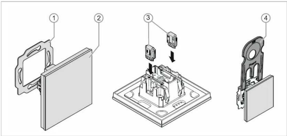
Fig. 1: Product overview
[1] Support ring [1]
[2] Flush-mounted insert with control element [2] (firmly installed unit)
[3] Clamps of removal protection [3] (optional)
[4] Removal tool [4] (optional)
4.2.2 Support rings
The support rings are partly different from country to country. The correct support ring is supplied according to country.
Country-specific support rings are for example:

Fig. 2: Country-specific support rings
[1] VDE Germany
[2] Switzerland / British standard (BS)
(The support ring for Switzerland is supplied without earth terminal)
[3] NEMA
[4] Italy
4.3 Functions
The following table provides an overview of the possible functions and applications of the device:
| Special features Function | |
| 4 channelsOpening angle 180°Freely programmableProtection type IP 205 - 500 lux | SwitchingValue transmitter |
Table 1: Overview of functions
4.4 Scope of supply

Fig. 3: Scope of delivery
Included in the scope of delivery are:
- Support ring [1]
- Flush-mounted insert with control element [2] (firmly installed unit)
- Clamps of removal protection [3] (optional)
- Removal tool [4] (optional)

Note
- Additional information about possible device versions is available in the electronic catalogue (www.busch-jaeger-catalogue.com).
4.5 Overview of types
Models of control elements preconfigured or freely configurable
| Article no. Product name | |
| TBW/U.x.x-xx | Busch-Watchdog 180° incl. BAU• V e r t i c a l• Horizontal |
Table 2: Models of control elements preconfigured or freely configurable
5 Technical data
5.1 Technical data
| Designation Value | |
| Power supply: 24 V DC (via bus line) | |
| KNX connectionBus connecting terminal, screwless:Line type:Wire stripping: | 0.6 - 0.8 mmJ-Y(St)Y, 2 x 2 x 0.8 mm5 - 6 mm |
| Opening angle: 180° | |
| Brightness limit value: 1 - 500 lux | |
| Mounting height: 1.1 m - 1.3 m | |
| Bus subscribers: 1 (≤12 mA) | |
| Temperature range: -5°C to +45°C | |
| Storage temperature: -20°C to +70°C | |
| Protection type: IP 20 |
Table 3: Technical data
5.2 Dimensional drawings
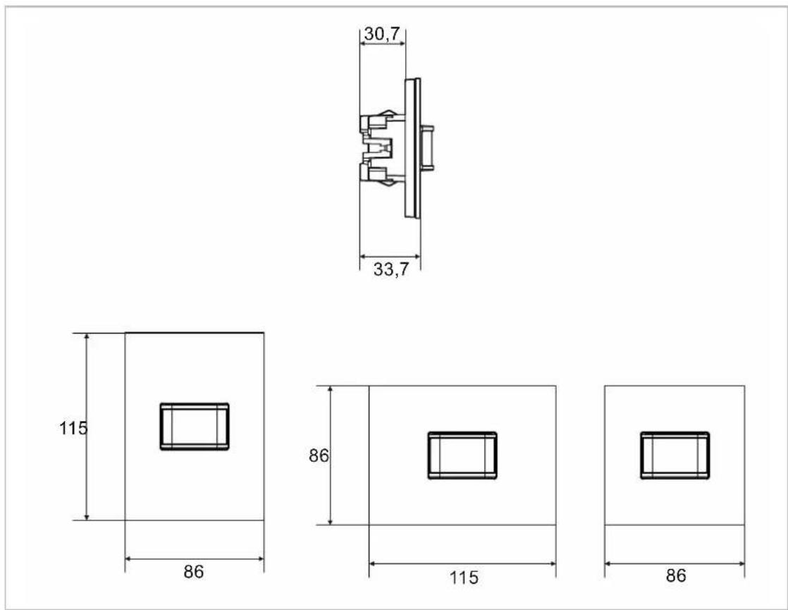
Fig. 4: Dimensions (all dimensions are in mm)
5.3 Detection range

Fig. 5: Detection range
[1] Mounting heights / Detection levels
[2] Detection range ( 0^ C - +36°C);
[3] Horizontal reduction of the detection range by masking
6 Connection, installation / mounting

Danger - Electric voltage!
Install the device only if you have the necessary electrical engineering knowledge and experience.
- Incorrect installation endangers your life and that of the users of the electrical system.
- Incorrect installation can cause serious damage to property, e.g. due to fire.
The minimum necessary expert knowledge and requirements for the installation are as follows:
- Apply the "five safety rules" (DIN VDE 0105, EN 50110):
- Disconnect
- Secure against being re-connected
- Ensure there is no voltage
- Connect to earth and short-circuit
-
Cover or barricade adjacent live parts.
-
Use suitable personal protective clothing.
- Use only suitable tools and measuring devices.
- Check the type of supply network (TN system, IT system, TT system) to secure the following power supply conditions (classic connection to ground, protective earthing, necessary additional measures, etc.).
- Observe the correct polarity.

Caution - Glass breakage!
The breakage of a glass plate could lead to the risk of injury.
Thr glass plate consists of high-quality safety glass. Yet breakage cannot be excluded.
- Avoid force being applied to the glass plate.
- Never reach into a broken glass with you bare hands.
6.1 Mounting

Caution! The device can sustain damage when coming into contact with hard objects!
The plastic parts of the device are sensitive.
– Pull the attachment off only with your hands.
- Do not lever parts off with screwdrivers or similar hard objects.
In Germany the flush-mounted insert must only be installed in flush-mounted boxes according to DIN 49073-1, Part 1, or suitable surface-mounted housings.
Different installation standards apply in other countries. These are to be taken into account when used in connection with a different support ring and flush-mounted box.
To install the device, perform the following steps:
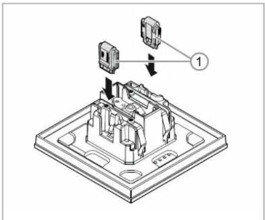
Fig. 6: Installation of the removal protection
Option
- Installing the removal protection.
- Push the removal protection into position by hand.
(The removal protection is not a component part of the device and is to be ordered separately.)

natural_image
Technical diagram of a mechanical assembly with circular component and flange (no text or symbols)Fig. 7: Installation of the support ring
- Installing the support ring.

Fig. 8: Connection of the bus line
- Pull the bus line out of the flush-mounted box and connect the line to the bus connection terminal [1], see chapter 6.2 "Electrical connection" on page 21.
- Check that the polarity is correct!

Fig. 9: Programming button
- To commission the device, see chapter 7 "Commissioning" on page 22.
- Programming is carried out via the programming button [1] on the rear of the device.
- Press the programming button [1].
- All LEDs [2] light up red.

natural_image
Diagram of a door or shelf assembly with a central component and directional arrow (no text or symbols)Fig. 10: Mounting devices
- Installing the device.
- Snap the device into the support ring by hand.
The device is now mounted.
6.2 Electrical connection

Fig. 11: Connection of bus coupler
Carry out the electrical connection according to the circuit diagram.
7 Commissioning
7.1 Hardware
The movement detectors must be mounted to a solid wall, since each movement of the device has the same effect as the movement of a heat source in the detection range.
- The optimum function of the movement detector is assured when it is mounted laterally to the direction of movement (tangential approach).
- Since infrared waves cannot penetrate solid objects, ensure that nothing obstructs the "line of vision" of the movement detector.
- A minimum distance of 2m is to be kept from the direct light of lamps.
Mounting heights / Detection levels
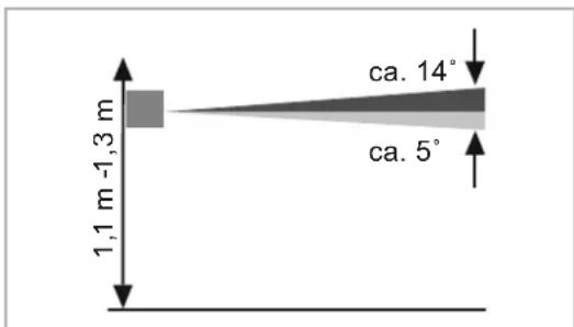
- The movement detector has a selective lens which has a detection level of approximately 3^ upwards and approximately 2^ downwards.
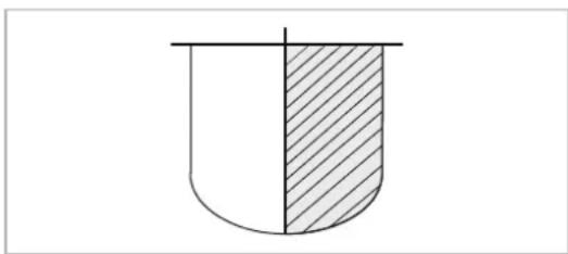
Detection range

- The detection range is 180^ , which is composed of two 90^ segments.
- The transmission range at a tangential / vertical approach amounts to at least 6 m.
Narrowing the detection range
natural_image
Simple diagram of a U-shaped container with a shaded half-section, no text or symbols present.- The detection range can be narrowed via the parameter setting within the Engineering Tool Software (ETS) (Power-Tool).
7.2 Software
To start the device a physical address must be assigned first. The physical address is assigned and the parameters are set with the Engineering Tool Software (ETS).

NOTE
The devices are products of the KNX system and meet KNX guidelines. Detailed expert knowledge by means of KNX training sessions for a better understanding is assumed.
7.2.1 Preparation
- Connect a PC to the KNX bus line via the KNX interface (e.g. via the commissioning interface / commissioning adapter 6149/21-500).
- The Engineering Tool Software must be installed on the PC (native application from ETS 4.0).
- Switch on the bus voltage.
7.2.2 Assigning a physical address

Fig. 12: Programming button
- Press the programming button [1].
- All LEDs [2] light up red.
7.2.3 Assigning the group address(es)
The group addresses are assigned in connection with the ETS.
7.2.4 Selecting the application program
Please contact our Internet support unit (www.BUSCH-JAEGER.com). The application is loaded into the device via the ETS.
7.2.5 Differentiating the application program
Various functions can be implemented via the ETS.
Detailed description of parameters, see chapter 11 "Description of application and parameters" on page 27 (only in languages DE, EN, ES, FR, IT and NL).
8 Updating options
A firmware update is carried out via the KNX bus by means of the ETS app "KNX Bus Update".

NOTE
The description of the update process can be downloaded via the electronic catalogue (www.busch-jaeger-catalogue.com). It is stored on the device page under category "Software".
9 Operation
The device is operated only via the programming button.
Details on operating the programming button is available at: see chapter 7.2.2 "Assigning a physical address" on page 23.
Further manual operations are not necessary.
The function is fixed via the assigned function and its parameter settings.
Extensive functions are available for the movement detectors. The range of applications is contained in Chapter 11 "Description of application and parameters" on page 27 (in languages of the countries DE, EN, ES, FR, IT, NL, PL and RU).

Note
The scope of delivery contains only the electronic insert. It must still be completed with a suitable cover frame.
Additional information about the switch ranges is available in the electronic catalogue (www.busch-jaeger-catalogue.com).
10 Maintenance
10.1 Maintenance-free device
The device is maintenance-free. In case of damage, e.g. during transport or storage), do not perform repairs. Once the device is opened, the warranty is void.
Access to the device must be guaranteed for operation, testing, inspection, maintenance and repairs (according to DIN VDE 0100-520).
10.2 Cleaning

Caution - Glass breakage!
The breakage of a glass plate could lead to the risk of injury.
Thr glass plate consists of high-quality safety glass. Yet breakage cannot be excluded.
- Avoid force being applied to the glass plate.
- Never reach into a broken glass with you bare hands.
Clean dirty devices with a soft dry cloth.
- If this is insufficient, the cloth can be moistened slightly with a soap solution.
11 Description of application and parameters
11.1 Application program
Available device:
- TBW/U.x.x-xx Busch-Watchdog 180° incl. BAU
The following application programs are available:
| Application program |
| Busch-Watchdog/1 |
The application program for the control elements contains the following applications:
| Parameter area KNX application | |
| Detector 1 - 4 Detector | |
| Brightness Brightness detection |
Depending on the application selected, the Engineering Tool Software (ETS) shows different parameters and communication objects.
11.2 Overview of functions
| Application Parameters Options | ||
| Application "Detector" — Detector x — General parameters | Output type Master / Slave | |
| Input slave No / Yes | ||
| Output is of type | 1 bit / 1 byte 0 - 100% / 1 byte 0 - 255 / Light scene number 1 - 64 / RTC operating mode switchover (1 byte) | |
| Output object sends at | On/Off / Switching on / Switching off | |
| Value for switching on | Setting dependent on "Output is of type" | |
| Sending value for switch-on cyclic No / Yes | ||
| Value for switching off | Setting dependent on "Output is of type" | |
| Send value for switch-off cyclic No / Yes | ||
| Cyclic repeat time (hh:mm:ss) | 00:00:10 - 18:12:15 (hh:mm:ss) | |
| Switch-OFF delay (hh:mm:ss) | 00:00:10 - 18:12:15 (hh:mm:ss) | |
| Brightness threshold internal (lux) 1 - 1000 | ||
| Fade in extended parameters No / Yes | ||
| Application "Detector" — Detector x — Extended parameter settings | Operating mode | Automatic / Switch-off automatic / Switch-on automatic / Monitoring |
| Use two-stage switch-off No / Yes | ||
| Value for reduced brightness | Setting dependent on "Output is of type" | |
| Brightness reduced according to switch-off delay (hh:mm:ss) | 00:00:10 - 18:12:15 (hh:mm:ss) | |
| Use forced switch-off No / Yes | ||
| Use object for switch-off delay No / Yes | ||
| Use object for switch-off delay reduced brightness | No / Yes | |
| Use object for test mode No / Yes | ||
| Use object actuator status No / Yes | ||
| Use object status manual on/off | No / Yes | |
| Pause time | 00.100 - 59.999 (ss.fff) | |
| Extension unit input takes pause time into account | No / Yes | |
| Overwrite settings at download No / Yes | ||
| Monitoring time window | 00:00:01 - 00:10:00 (hh:mm:ss) | |
| Minimum activity in the monitoring time window | 10%, 20% - 100% | |
| Application "Detector" — Detector x — Brightness | Use object for detection independent of brightness | No / Yes |
Description of application and parameters
Overview of functions
| parameters | Brightness-independent detection activation with | On telegram / Off telegram |
| Brightness independent detection after bus voltage recovery | No / Yes | |
| Input Slave takes the brightness into consideration | No / Yes | |
| Used brightness | Independent of brightness / only internal / only external / internal or external | |
| Use object for internal brightness-value threshold | No / Yes | |
| Use object for external brightness-value threshold | No / Yes | |
| Brightness threshold external (lux) 1 - 1000 | ||
| Application "Detector" — Detector x — Parameter external push-button | Use object input external push-button No / Yes | |
| External button switches on with | On telegram / Off telegram | |
| Use object input manual operation No / Yes | ||
| Manual mode is activated with | On telegram / Off telegram | |
| Application "Detector" — Detector x — Sensor selection | Sensor sensitivity 1 | Maximum / high / medium / low / off |
| Sensor sensitivity 2 | Maximum / high / medium / low / off | |
| Application "Detector" — Detector x — Enabling | Use enable object detector No / Yes | |
| Enable delay | 00:00:01 - 00:10:00 (hh:mm:ss) | |
| Enable with | On telegram / Off telegram | |
| After bus voltage recovery detector is Disabled / enabled | ||
| Output sends at enable | No telegram / current status / single value for switching on / single value for switching off | |
| Output sends at blockage | No telegram / off after expiry of switch-off delay / single value for switching off / single value for switching on / immediate off | |
| "Brightness detection" application - Brightness - General parameters | Sending of brightness, all (hh:mm:ss) | 00:00:05 - 18:12:15 (hh:mm:ss) |
| Use object for LED No / Yes | ||
| Correction of internal brightness No / with daylight adjustment | ||
| Fade in extended parameters No / Yes | ||
| "Brightness detection" application - Brightness - Extended parameters | Use internal brightness No / Yes | |
| Number of external brightness measurement objects | 1 / 2 | |
| Weighting of internal brightness 1 - 100 | ||
| Weighting of external brightness 1 1 - 100 | ||
| Weighting of external brightness 2 1 - 100 | ||
Description of application and parameters
Overview of functions
| Brightness output sends | Cyclic / cyclic and at a value change | |
| Brightness difference for immediate transmission (%) | 1 - 100 (%) | |
| Cycle time for brightness monitoring | 00:00:30 - 18:12:15 (hh:mm:ss) | |
| Alarm object | Is deactivated / sends cyclic / sends only at a change | |
| Overwrite settings for download No / Yes |
Table 4: Overview of applications and functions
11.3 "Detector" application
| Options: Inactive Detector | |
- Inactive:
– Application is not active. - Detector
– Application is active.
The application is used to specify the monitoring functions, the brightness settings and the sensitivity of the movement detector. When the application is active, a telegram is sent on the KNX bus at a detection of movement.
Depending on the type of the output object and the operating mode, the following output communication objects are available:
- "Mx: Movement (master)"
- "Mx: Movement (slave)"
- "Mx: Monitoring"

Note
The following parameters can only be adjusted when the application is activated. The parameters of detectors 1 to 4 can be called up via:
- General parameters
- Extended parameter settings
- Brightness parameter
- External button parameter
- Sensor selection
- Enable

Note
The numbers (M1 - Mx) of the communication objects depend on the detector selected.
11.3.1 General parameters
11.3.1.1 Output type
| Options: MasterSlave | |
Master:
- In master mode On and Off telegrams are sent (to an actuator) dependent on movement.
- Slave:
- In slave mode On telegrams are sent cyclically (to the "input slave or slave input" of a master detector) when movement is detected.

Note
The parameter is only adjustable if the "Operating mode" parameter is not set on "Monitoring".
11.3.1.2 Input Slave
| Options: NoYes | |
No:
- Communication object is not enabled.
Yes:
- Communication object "Mx: Slave" is enabled.
The 1-bit communication object "Mx: slave" (Input) can be enabled with this parameter. The movement detector configured as master receives telegrams of the connected slave detector or an external push-button via the object.
A telegram received via communication object "Mx: slave" is evaluated as recognized movement.

Note
The parameter is only adjustable if the "Output type" parameter is set on "Master" and the "Operating mode" parameter is not set on "Monitoring".
11.3.1.3 Output is of type
| Options: 1 bit | |
| 1 byte 0 - 100% | |
| 1 byte 0 - 255 | |
| Light scene number 1-64 | |
| RTC operating mode switchover (1 byte) | |
- 1 bit :
- Value is sent as 1-bit switching commands (0 or 1), e.g. On/Off, enabled/blocked, true/untrue.
- 1 byte 0 - 100%:
- Value is sent as 1-byte value without a sign (percentage value) (0 = 0%, 255 = 100%)
- 1 byte 0 - 255:
- Value is sent as 1-byte value without a sign. Any value 0 - 255.
- Light scene number 1 - 64:
- Value is sent as scene number or scene control (1 - 64).
- RTC operating mode switchover (1 byte):
- Value is sent as 1-byte value for the RTC operating mode switchover, e.g. auto, comfort, ECO), when the room temperature controller has been linked.

Note
The parameter is only adjustable if the "Output type" parameter is set on "Master" and the "Operating mode" parameter is not set on "Monitoring".
11.3.1.4 Output object sends at
| Options: Switch-on / switch-off | |
| Switch-on | |
| Switch-off |
- Switch-on / switch-off:
- Output object sends a telegram at the start of movement and at the end of switch-off delay.
- Switching on:
- Output object sends a telegram only at the start of movement.
- Switching off:
- Output object sends a telegram only at the end of the switch-off delay.

Note
The parameter can only be set when parameter "Output type" is set on "Master".
11.3.1.5 Value for switching on
The possible options depend on parameter "Output is of type".
Options for selection "1 bit":
| Options: OffOne | |
Options for selection "1 byte 0-100%":
| Options: Setting option from 0 to 100 (%) |
Options for selection "1 byte 0-255":
| Options: Setting option from 0 to 255 |
Options for selection "Light scene number (1-64)":
| Options: Setting option from 1 to 64 |
Options for selection "RTC operating mode switchover (1 byte)":
| Options: Auto | |
| Comfort | |
| Standby | |
| ECO | |
| Frost/heat protection |
The parameter is used to set the value that is sent when a movement is detected.

Note
The parameter can only be set when parameter "Output type" is set on "Master" and parameter "Output object sends at" is set on "Switch on" or "Switch on/switch off".
11.3.1.6 Sending value for switch-on cyclic
| Options: NoYes | |
No:
- The setpoint is sent only once.
Yes:
- The setpoint is sent cyclic.

Note
The parameter can only be set when parameter "Output type" is set on "Master" and parameter "Ouput object sends at" is set on "Switch on" or "Switch on/switch off".
11.3.1.7 Value for switching off
The possible options depend on parameter "Output is of type".
Options for selection "1 bit":
| Options: OffOne | |
Options for selection "1 byte 0-100%":
| Options: Setting option from 0 to 100 (%) |
Options for selection "1 byte 0-255":
| Options: Setting option from 0 to 255 |
Options for selection "Light scene number (1-64)":
| Options: Setting option from 1 to 64 |
Options for selection "RTC operating mode switchover (1 byte)":
| Options: Auto | |
| Comfort | |
| Standby | |
| ECO | |
| Frost/heat protection |
The parameter is used to set the value that is sent when movement is now no longer detected and the switch-off delay has expired.

Note
The parameter can only be set when parameter "Output type" is set on "Master" and parameter "Output object sends at" is set on "Switch off" or "Switch on/switch off".
11.3.1.8 Send value for switch-off cyclic
| Options: NoYes | |
No:
- The setpoint is sent only once.
Yes:
- The setpoint is sent cyclic.

Note
The parameter can only be set when parameter "Output type" is set on "Master" and parameter "Output object sends at" is set on "Switch off" or "Switch on/switch off".
11.3.1.9 Cyclic repeat time (hh:mm:ss)
| Options: Setting option from 0 | 0:00:10 to 18:12:15 (hh:mm:ss) |
The telegrams of the output object are sent cyclic on the bus.
The parameter specifies the time interval from which a new sending of the telegrams occurs.

Note
The parameter can only be set when parameter "Cyclic sending of value for switch-on" and/or parameter "Cyclic sending of value for switch-off" is set on "Yes".
11.3.1.10 Switch-OFF delay (hh:mm:ss)
| Options: Setting option from 0 | 0:00:10 to 18:12:15 (hh:mm:ss) |
The parameter is used to set the time period between the last detected movement and the sending of a telegram. If further movement is detected within this period, the timer for the switch-off delay is restarted.

Note
The parameter can only be set when parameter "Output type" is set on "Master" and parameter "Operating mode" is set on "Automatic" or "Automatic switch-off".
11.3.1.11 Brightness threshold internal (lux)
| Options: Setting option from 1 to 1000 |
The parameter is used to set the internal brightness-value threshold for the light sensor of the movement detector.
Movement is detected only when the brightness threshold drops below its set value. This means that the "Value for switch-on" is sent via output object "Mx: movement (master/slave)" only when the lux value drops below its set value.

Note
The parameter is only adjustable if the "Operating mode" parameter is set on "Automatic" or "Automatic switch-on".

Note
The adjustable brightness limit value is available in the technical data of the device.
11.3.1.12 Fade in extended parameters
| Options: NoYes | |
No:
- Only the most important parameters for setting the detector are displayed.
■ Yes:
- The extended parameters are displayed, also those that are not required in most cases.
The parameter enables additional functions, e.g. "Extended parameter settings".
11.3.2 Extended parameter settings
11.3.2.1 Operating mode
| Options: Automatic mode | |
| Automatic switch-off | |
| Automatic switch-on | |
| Surveillance |
Automatic:
– Automatic switch-on and switch-off.
The detector switches on automatically when detecting a movement. The switch-off is effected after the set switch-off delay starting from the last detection.
- Automatic switch-off:
- Automatic switch-on and switch-off.
The detector or the light must be switched on manually via an external push-button (communication object "Mx: external push-button"). The switch-off is effected automatically under consideration of the switch-off delay.
- Automatic switch-on:
- Automatic switch-on and switch-off.
The detector switches on automatically at detection of movement. The switch-off is effected by the receipt of an Off telegram via the communication object "Mx: external push-button".

Note
The detector switches off automatically after six hours.
- Surveillance
– Automatic switch-on and switch-off.
The detector switches on independent of the brightness when an adjustable portion of movement is detected within the set period. The switch-off occurs two seconds after the switch-on and the last detection of movement.
During manual switch-off the detection of movement is suppressed for the pause time. The pause time serves to prevent an immediate switch-on.
Example: A user switches the light off manually and leaves the room. The pause time prevents the detected movement to cause a renewed switch-on of the lights during exiting of the room.

Note
The parameter can only be set when parameter "Output type" is set on "Master".

Note
The parameters for the external push-button and manual operation are set under parameter external push-button. The pause time is set under extended parameter settings.
11.3.2.2 Use two-stage switch-off
| Options: NoYes | |
No:
- After the switch-off delay set under general parameters, the detector sends the value that is set under parameter "Value for switching off".
Yes:
- After the switch-off delay set under general parameters, the detector switches to the reduced brightness.
- Then, according to the time set under parameter "Brightness reduced according to switch-off delay", the detector sends the value set under "Value for switching off".
Example:
- Switch-off delay: 5 minutes.
■ Value for switching off: 0%.
■ Value for reduced brightness: 20%. - Brightness reduced according to switch-off delay: 3 minutes.
If movement is no longer detected, the light is dimmed to 20% after 5 minutes and then to 0% after a further 3 minutes (switch-off).

Note
The parameter can only be set when parameter "Output is of type" is set on "1 byte 0-100%" or "1 byte 0-255" and parameter "Operating mode" is set on "Automatic" or "Automatic switch-off".
11.3.2.3 Value for reduced brightness (%)
The possible options depend on parameter "Output is of type".
Options for selection "1 byte 0-100%":
| Options: Setting option from 0 to 100 (%) |
Options for selection "1 byte 0-255":
| Options: Setting option from 0 to 255 |
The parameter is used to set the brightness value to which the device is to dim the light after the switch-off delay has expired.

Note
The parameter can only be set when parameter "Output is of type" is set on "1 byte 0-100%" or "1 byte 0-255" and parameter "Operating mode" is set on "Automatic" or "Automatic switch-off" and parameter "Use of two-stage switch-off" is set on "Yes".
11.3.2.4 Brightness reduced according to switch-off delay (hh:mm:ss)
| Options: Setting option from 0 | 0:00:10 to 18:12:15 (hh:mm:ss) |
The parameter is used to set the value for the switch-off delay of the reduced brightness. The total switch-off delay then consists of the switch-off delay and the "Brightness reduced according to switch-off delay".

Note
The parameter can only be set when parameter "Operating mode" is set on "Automatic" or "Automatic switch-off" and parameter "Use of two-stage switch-off" is set on "Yes".
11.3.2.5 Use forced switch-off
| Options: NoYes | |
No:
- The detector does not switch off after a specified time to carry out a new brightness measurement
Yes:
- The detector switches off once after a triple switch-off delay or after 90 minutes up to a maximum of 24 hours, to carry out a new brightness measurement
If the movement detector is switched on, it operates independent of brightness. This leads to the effect that the light remains on when movement is detected, even when it is already light. This effect can be prevented by activating this parameter.

Note
The parameter is only adjustable if the "Operating mode" parameter is set on "Automatic" or "Automatic switch-off".
11.3.2.6 Use object for switch-off delay
| Options: NoYes | |
No:
- Communication object "Mx: switch-off delay" is not enabled. The switch-off delay is firmly set via the "Switch-off delay" parameter.
- Yes:
- Communication object "Mx: switch-off delay" is enabled.
The 2-byte communication object "Mx: switch-off delay" can be enabled with this parameter. The switch-off delay of the detector can be changed via the object. The time is sent in seconds.

Note
Values from 10 to 65535 seconds can be sent.
Sent values that are outside this range are adjusted automatically to the limit values. This means that values < 10 are set to value "10". Values > 65535 are set to value "65535".

Note
The parameter is only adjustable if the "Operating mode" parameter is set on "Automatic" or "Automatic switch-off".
11.3.2.7 Use object for switch-off delay reduced brightness
| Options: NoYes | |
No:
- Communication object "Mx: switch-off delay reduced brightness" is not enabled. The switch-off delay is firmly set via the "Switch-off delay reduced brightness" parameter.
Yes:
- Communication object "Mx: switch-off delay reduced brightness" is enabled.
The 2-byte communication object "Mx: switch-off delay reduced brightness" can be enabled with this parameter. The switch-off delay for the reduced brightness of the detector can be changed via the object. The time is sent in seconds.

Note
Values from 10 to 65535 seconds can be sent.
Sent values that are outside this range are adjusted automatically to the limit values. This means that values < 10 are set to value "10". Values > 65535 are set to value "65535".

Note
The parameter can only be set when parameter "Output is of type" is set on "1 byte 0-100%" or "1 byte 0-255", parameter "Operating mode" is set on "Automatic" or "Automatic switch-off" and parameter "Use of two-stage switch-off" is set on "Yes".
11.3.2.8 Use object for test mode
| Options: NoYes | |
No:
- Communication object "Mx: activate test mode" is not enabled.
Yes:
- Communication object "Mx: activate test mode" is enabled.
The 1-bit communication object "Mx: activate test mode" can be enabled with this parameter. If an On telegram is received via the object, the test mode is activated. If an Off telegram is received via the object, the test mode is deactivated. If no Off telegram is received, the test mode is automatically deactivated after ten minutes.
During test mode, the programming LED displays on the movement detector that movement detection is active. The device operates independent of brightness with a switch-off delay of 2 to 9 seconds.

Note
The parameter is only adjustable if the "Operating mode" parameter is set on "Automatic" or "Automatic switch-off".
11.3.2.9 Use object actuator status
| Options: NoYes | |
No:
- Communication object "Mx: actuator status" is not enabled.
Yes:
- Communication object "Mx: actuator status" is enabled.
The 1-bit communication object "Mx: actuator status" can be enabled with this parameter. The status of a switch actuator, for example, can be received via the object. When the actuator is switched off via a central command, the movement detector is informed about this via object "Mx: actuator status" and is ready immediately for switch-on after the pause time.

Note
The parameter is only adjustable if the "Operating mode" parameter is not set on "Monitoring".
11.3.2.10 Use object status manual on/off
| Options: NoYes | |
No:
- Communication object "Mx: status manual on/off" is not enabled.
Yes:
- Communication object "Mx: status manual on/off" is enabled.
The 1-bit communication object "Mx: status manual on/off" (output) can be enabled with this parameter. When the movement detector is deactivated and only a manual operation is possible via the external push-button, an On telegram is sent via the object. When the detector is set to automatic mode, an Off telegram is sent via the object.

Note
The parameter is only adjustable if the "Operating mode" parameter is not set on "Monitoring" and parameter "Use object input external push-button" is set on "Yes".
11.3.2.11 Pause time
| Options: Setting option from 0 | 0.100 to 59.999 (ss.fff) |
The parameter is used to set the pause time that is started when the movement detector has been deactivated due to the expiry of the switch-off delay or by an Off telegram via objects "Mx: external push-button" or "Mx: actuator status".
If movement is detected during the pause time, the detector is not activated immediately. The pause time is first extended by seven seconds. If a further movement is detected after the extension period, the detector switches on again.
If no movement is detected during the pause time, the detector is ready for activation again after the pause time. This behaviour can, for example, be important when the lamp cools down drastically and is located within the detection range of the detector. Without a blockage there would be an unintentional switch-on. The pause time serves to prevent an immediate switch-on.
Example: A user switches the light off manually and leaves the room. The pause time prevents the detected movement to cause a renewed switch-on of the lights during exiting of the room.
11.3.2.12 Extension unit input takes pause time into account
| Options: NoYes | |
No:
- The extension unit input immediately executes the command received. The detector responds immediately.
Yes:
- The extension unit input executes the command received only after the set pause time. The response of the detector delays (after the expiry of the pause time).
The parameter is used to specify whether the movement detector switches the light on immediately or after the expiry of the pause time if a switching command is received via the extension unit input.

Note
The parameter can only be set when parameter "Output type" is set on "Master", parameter "Slave input" is set on "Yes" and parameter "Operating mode" is set on "Automatic" or "Automatic switch-on".
11.3.2.13 Overwrite settings at download
| Options: NoYes | |
No:
- Settings are not overwritten during a download of the application.
Yes:
- When reprogramming the detector, the values changed via the bus are overwritten with the preset values in the parameterisation software.
The parameter is used to specify whether the current settings are overwritten during the download of the application or are retained.
The following parameters will be overwritten:
- "Switch-off delay"
- "Brightness reduced according to switch-off delay"
■ "Brightness threshold internal (lux)"
- "Brightness threshold internal (lux)"
11.3.2.14 Monitoring time window
Options: Setting option from 00:00:01 to 00:10:00 (hh:mm:ss)
The movement detector operates independent of brightness in "Monitoring" operating mode. The parameter is used to set the time window during which movement is detected and a switching signal is sent.
The parameter "Minimum activity in the time window" is used to specify how much movement must be detected for a telegram to be sent on the bus via object "Mx: monitoring".
Example: For a time window of 10 seconds and minimum activity of 50% the detector sends a telegram on the bus at a movement of at least 5 seconds.

Note
The parameter is only adjustable if the "Operating mode" parameter is set to "Monitoring".
The minimum activity is set via parameter "Minimum activity in the monitoring time window".
11.3.2.15 Minimum activity in the monitoring time window
| Options: 10% | |
| 20% | |
| 30% | |
| 40% | |
| 50% | |
| 60% | |
| 70% | |
| 80% | |
| 90% | |
| 100% |
10% - 100%:
The parameter is used to specify how much movement is to be detected within the monitoring time window so that the movement detector sends a switching signal via object "Mx: monitoring".

Note
The parameter is only adjustable if the "Operating mode" parameter is set to "Monitoring".
The monitoring time window is set via parameter "Monitoring time window".
11.3.3 Parameter brightness

Note
The following parameters can only be set if the "Operating mode" parameter is set on "Automatic" or "Automatic switch-on" and parameter "Used brightness" is not set on "Brightness independent".
Parameter "Operating mode" can be called up via extended parameter settings.
11.3.3.1 Use object for detection independent of brightness
| Options: No | |
| Yes |
No:
- Communication object "Mx: brightness independent detection" is not enabled.
Yes:
- Communication object "Mx: brightness independent detection" is enabled.
The 1-bit communication object "Mx: brightness independent detection" can be enabled with this parameter. The movement detector can be switched via the object independent of brightness.

Note
The parameter can only be set if the "Used brightness" parameter is not set on "Brightness independent".
11.3.3.2 Brightness-independent detection activation with
| Options: On telegramOff telegram | |
- ON telegram:
- Activation of function via On telegram.
- Off telegram:
- Activation of function via Off telegram.
The parameter is used to specify whether the brightness-independent movement detection is activated with an On telegram or Off telegram. The switching signal is received via the communication object "Mx: brightness independent detection".

Note
The parameter can only be set when the "Use of object for detection independent of brightness" parameter is set on "Yes".
11.3.3.3 Brightness independent detection after busvoltage return
| Options: NoYes | |
No:
- Automatic deactivation of brightness-independent detection after bus voltage recovery.
Yes:
- Automatic activation of brightness-independent detection after bus voltage recovery.
If the start of the brightness-independent movement detection is to be automatic after the bus voltage recovery or a reset, the parameter must be set on "Yes". If "No" is selected, the brightness-independent detection of movement is not started after the bus voltage recovery.

Note
The parameter can only be set when the "Use of object for detection independent of brightness" parameter is set on "Yes".
11.3.3.4 Input Slave takes the brightness into consideration
| Options: NoYes | |
No:
- If an ON telegram is received via object "Mx: Slave", the detector switches or the switch-off delay is reset. The detector also switches when the measured brightness lies above the brightness-value threshold.
Yes:
- If an ON telegram is received via object "Mx: slave", the detector only switches when the measured brightness lies below the brightness-value threshold.
The parameter is used to specify whether the measured brightness is taken into account during ON telegrams via communication object "Mx: slave".
11.3.3.5 Used brightness
| Options: Brightness-independent | |
| Internal only | |
| External only | |
| Internal or external | |
- Brightness-independent
- The detector detects movement independent of brightness and switches at each movement.
- Internal only:
- The detector uses the brightness it measured and switches at movement when the threshold set via parameter "Brightness threshold internal (lux)" drops below the set value.
- External only
- Communication object "Mx: external brightness" is enabled.
- The detector uses the external brightness measured and switches at movement when the threshold set via parameter "Brightness threshold external (lux)" drops below the set value.
- Internal or external
- Communication object "Mx: external brightness" is enabled.
- The detector uses the brightness measured internal and external. The device switches at movement when the threshold set via parameter "Brightness threshold internal (lux)" drops below the set value or when the threshold set via parameter "Brightness threshold external (lux)" drops below the set value.
The parameter is used to specify whether the detector uses the brightness it measured or the externally measured brightness or detects movement independent of the current brightness.
11.3.3.6 Use object for internal brightness-value threshold
| Options: NoYes | |
No:
- Communication object "Mx: brightness threshold internal" is not enabled.
Yes:
- Communication object "Mx: brightness threshold internal" is enabled.
The 2-byte communication object "Mx: brightness threshold internal" can be enabled with this parameter. The internal brightness-value threshold can be adjusted via the object at which the movement detector is activated. The value is sent in lux.

Note
The parameter can only be set if the "Used brightness" parameter is set on "only internal" or on "internal or external".
11.3.3.7 Use object for external brightness-value threshold
| Options: NoYes | |
No:
- Communication object "Mx: brightness threshold external" is not enabled.
Yes:
- Communication object "Mx: brightness threshold iexternal" is enabled.
The 2-byte communication object "Mx: brightness threshold external" can be enabled with this parameter. The external brightness-value threshold can be adjusted via the object at which the movement detector is activated. The value is sent in lux.

Note
The parameter can only be set if the "Used brightness" parameter is set on "only external" or on "internal or external".
11.3.3.8 Brightness threshold external (lux)
| Options: Setting option from 1 to 1000 |
The parameter is used to set the externally measured brightness at which the movement detector switches. Movement is detected only when the brightness threshold drops below its set value. This means that a switching telegram is sent via output object "Mx: movement (master/slave)" only when the lux value drops below its set value.

Note
The parameter can only be set if the "Used brightness" parameter is set on "only external" or on "internal or external".

Note
The adjustable brightness limit value is available in the technical data of the external device.
11.3.4 Parameter external pushbutton

Note
The following parameters are only adjustable if the "Operating mode" parameter is not set on "Monitoring".
Parameter "Operating mode" can be called up via extended parameter settings.
11.3.4.1 Use object input external push-button
| Options: NoYes | |
No:
- Communication object "Mx: external push-button" is not enabled.
Yes:
- Communication object "Mx: external push-button" is enabled.
The 1-bit communication object "Mx: external push-button" can be enabled with this parameter. The movement detector can be switched via the object from an external position. The object is used especially in the "Automatic switch-on" mode for switch-off and in "Automatic switch-off" mode for switch-on.

Note
The parameter is only adjustable if the "Operating mode" parameter is set to "Automatic". For setting "Automatic switch-on" or "Automatic switch-off" the object "Mx: external push-button" is automatically enabled.
11.3.4.2 External button switches on with
| Options: On telegramOff telegram | |
- ON telegram:
- Activation of the detector via On telegram.
- Off telegram:
- Activation of the detector via Off telegram.
The parameter is used to specify whether the movement detector is activated with an On telegram or Off telegram. The switching signal is received via the communication object "Mx: external push-button".

Note
The parameter can only be set when the "Use object input external push-button" parameter is set on "Yes".
11.3.4.3 Use object input manual operation
| Options: NoYes | |
No:
- Communication object "Mx: switchover to manual operation" is not enabled.
Yes:
- Communication object "Mx: switchover to manual operation" is enabled.
The 1-bit communication object "Mx: switchover to manual operation" (input) status" can be enabled with this parameter. If an On telegram is received via the object, movement detection is deactivated and the detector can then only be switched manually via object "Mx: external push-button". An Off telegram resets the detector to automatic mode.

Note
The parameter can only be set when the "Use object input external push-button" parameter is set on "Yes".
11.3.4.4 Manual mode is activated with
| Options: On telegramOff telegram | |
- ON telegram:
- Movement detection of the detector is deactivated via an On telegram.
- Off telegram:
- Movement detection of the detector is deactivated via an Off telegram.
The parameter is used to specify whether the movement detection is deactivated with an On telegram or Off telegram. The switching signal is received via the communication object "Mx: switchover to manual operation".

Note
The parameter can only be set when the "Use object input manual operation" parameter is set on "Yes".
11.3.5 Choice of sensor
11.3.5.1 Sensor sensitivity 1/2
| Options: Maximum | |
| Up | |
| Medium | |
| Low | |
| Off |
- Maximum:
– Highest sensitivity. Setting at coverage increase.
High:
– Standard sensitivity for the internal area.
Medium:
- Recommended sensitivity for smaller heat sources in the visual area of the sensor.
Low:
- Recommended sensitivity for larger heat sources in the visual area of the sensor.
Off:
- The sensor is deactivated and the detector does not detect movement.
The parameter us used to specify the sensitivity of movement detector.

Note
The transmission range can not be changed via the sensitivity.
11.3.6 Enable
11.3.6.1 Use enable object detector
| Options: NoYes | |
No:
- Communication object "Mx: enable movement" is not enabled.
Yes:
- Communication object "Mx: enable movement" is enabled.
The 1-bit communication object "Mx: enable movement" can be enabled with this parameter. The movement detector can be temporarily blocked via this object. No telegrams are sent from the detector during the blockage.
11.3.6.2 Enable delay
Options: Setting option from 00:00:01 to 00:10:00 (hh:mm:ss)
At the receipt of a telegram the device is enable only after the delay time has expired. The parameter is used to set the delay time.

Note
The parameter is only adjustable if the "Operating mode" parameter is set on "Monitoring" and parameter "Use of enable detector object" is set on "Yes". Parameter "Operating mode" can be called up via extended parameter settings.
11.3.6.3 Enable with
| Options: On telegramOff telegram | |
- ON telegram:
- The device is enabled via an On telegram.
- Off telegram:
- The device is enabled via an Off telegram.
The movement detector is normally enabled with the receipt of an ON telegram (value "1") via 1-bit communication object "Mx: enable movement" (input) and blocked with an OFF telegram (value "0"). The parameter can invert this behaviour.

Note
The parameter is only adjustable if the "Use of enable detector object" parameter is set on "Yes".
11.3.6.4 After bus voltage recovery detector is
| Options: BlockedEnabled | |
- Blocked:
- After bus voltage recovery the device is blocked.
- Enabled:
- After bus voltage recovery the device is enabled.
If the movement detector is to switch directly into automatic mode after bus voltage recovery or a reset, the parameter must be set on "enable". If "blocked" is selected, the detector is blocked after bus voltage recovery and must be enabled for automatic operation via object "Mx: enable movement".

Note
The parameter is only adjustable if the "Use of enable detector object" parameter is set on "Yes".
11.3.6.5 Output sends at enable
The possible options depend on parameter "Operating mode".
Options for selection of "Automatic", "Switch-off automatic", "Switch-on automatic" or "Automatic switch-on":
| Options: No telegram | |
| Current status | |
| Single value for switching on | |
| Single value for switching off |
Options for selection "Monitoring":
| Options: No telegram | |
| Single value for switching off |
- No telegram:
- No telegram is sent at enable.
- Current status:
- During enable, the detector checks whether a movement has occurred and the brightness is below the brightness-value threshold. When both conditions have been met, the device sends a switch-on telegram once. When only one or no condition has been met, the device sends a switch-off telegram.
- Single value for switching on:
- At enable, a single value that has been set via parameter "Value for switching on" is sent.
- Single value for switching off:
- At enable, a single value that has been set via parameter "Value for switching off" is sent.
The parameter is used to specify the value that is sent on the bus after the device has been enabled.

Note
The parameter is only adjustable if the "Use of enable detector object" parameter is set on "Yes".
11.3.6.6 Output sends at blockage
The possible options depend on parameter "Operating mode".
Options for selection of "Automatic", "Switch-off automatic", "Switch-on automatic" or "Automatic switch-on":
| Options: No telegram | |
| Off after expiration of the switch-off delay | |
| Single value for switching off | |
| Single value for switching on | |
Options for selection "Monitoring":
| Options: No telegramImmediately OFF | |
- No telegram:
- No telegram is sent at blockage.
- Off after expiration of the switch-off delay:
- The switch-off delay is reset at a blockage. After expiry of the newly started switch-off delay, the detector sends the value that has been set via parameter "Value for switch-off".
- Single value for switching off:
- At a blockage, a single value that has been set via parameter "Value for switching off" is sent.
- Single value for switching on:
- At a blockage, a single value that has been set via parameter "Value for switching on" is sent.
- Immediately off (only adjustable if the "Operating mode" is set on "Monitoring"):
- A switch-off telegram is sent via the output object at blockage.
The parameter is used to specify the value that is sent on the bus after the device has been blocked.

Note
The parameter is only adjustable if the "Use of enable detector object" parameter is set on "Yes".
11.4 "Brightness detection" application
| Options: InactiveBrightness detection | |
- Inactive:
– Application is not active. - Brightness detection:
– Application is active.
The application is used to specify the parameters for brightness detection and brightness monitoring.
The following output communication objects are available:
- "BR: Brightness"
- "BR: Alarm"

Note
The parameters for application "Brightness detection" can be called up via general parameters and extended parameters.
11.4.1 General parameters
11.4.1.1 Sending of brightness, all (hh:mm:ss)
| Options: Setting option from 0 | 0:00:05 to 18:12:15 (hh:mm:ss) |
The parameter is used to set how often the measured brightness values are sent on the bus.
11.4.1.2 Use object for LED
| Options: NoYes | |
No:
- Communication object "BR: LED" is not enabled.
Yes:
- Communication object "BR: LED" is enabled.
The 1-bit communication object "BR: LED" (Input) can be enabled with this parameter. The programming LED of the device can be switched on and off via the object.

Note
Only the LED has been switched via the communication object. This does not place the device into programming mode.
11.4.1.3 Correction of internal brightness
| Options: Nowith daylight adjustment | |
No:
- The internal brightness sensor is not calibrated.
- With daylight adjustment:
- The internal brightness sensor is calibrated.
The parameter is used to specify whether the sensitivity of the brightness sensor is adjusted to the daylight. With the setting "With daylight adjustment" the communication object "BR: brightness adjustment (Daylight)" is enabled.
The brightness correction is mainly used for the "Detector" application.
11.4.1.4 Fade in extended parameters
| Options: NoYes | |
No:
- Only the most important parameters for the brightness detection are displayed.
Yes:
- The extended parameters are displayed, also those that are not required in most cases.
The parameter enables additional functions under Extended parameters.
11.4.2 Extended parameters

Note
The following parameters can only be set when parameter "Fade in extended parameters" is set on "Yes". The parameter ia called up via general parameters.
11.4.2.1 Use internal brightness
| Options: NoYes | |
No:
- The internal brightness sensor is not used. The brightness values must be sent from the external brightness sensors.
Yes:
- The internal brightness sensor is used as encoder for the different detector applications. The parameter is effective only for this application.
The parameter is used to specify whether the brightness value of the internal device sensor is used.
11.4.2.2 Number of external brightness measurement objects
| Options: 12 | |
1:
- Only communication object "BR: external brightness 1" is enabled.
2:
- Also object "BR: external brightness 2" is enabled in addition to communication object "BR: external brightness 1".
Up to two external brightness sensors can be connected. The brightness values of the external sensors are received via communication objects "BR: external brightness 1/2" (Input). The brightness values of the internal brightness sensor are not used.

Note
The parameter is only adjustable if the "Use internal brightness" parameter is set on "No".
11.4.2.3 Weighting of internal brightness
| Options: Setting option from 1 to 100 |
The parameter is used to weight the brightness value of the internal sensor higher, equal to or lower than the values of the external sensors. The averaged value is then used for the brightness detection. Input in percent.

Note
The total of all weighting values must not exceed the value of "100".
For example:
Weighting internal sensor: 50%
Weighting of external sensor 1: 30%
Weighting of external sensor 2: 20%
Total weighting: 100%

Note
This parameter is only adjustable if the "Use of internal brightness" parameter is set on "yes" and the "Number of external brightness measurement objects" parameter is set on "1" or "2".
11.4.2.4 Weighting of external brightness 1
| Options: Setting option from 1 to 100 |
The parameter is used to weight the brightness value of the first external sensor higher, equal to or lower than the values of the internal and/or the second external sensor. The averaged value is then used for the brightness detection. Input in percent.

Note
The total of all weighting values must not exceed the value of "100".
For example:
Weighting internal sensor: 50%
Weighting of external sensor 1: 30%
Weighting of external sensor 2: 20%
Total weighting: 100%

Note
The parameter is only adjustable if the "Number of external brightness measurement objects" parameter is set on "1" or "2".
11.4.2.5 Weighting of external brightness 2
| Options: Setting option from 1 to 100 |
The parameter is used to weight the brightness value of the second external sensor higher, equal to or lower than the values of the internal and/or the first external sensor. The averaged value is then used for the brightness detection. Input in percent.

Note
The parameter is only adjustable if the "Number of external brightness measurement objects" parameter is set on "2".
11.4.2.6 Brightness output sends
| Options: CyclicCyclic and at a value change | |
Cyclic:
- The brightness value is sent at fixed intervals.
- Cyclic and at a value change:
- The brightness value is sent at fixed intervals and at every change of the brightness value.
The parameter is used to specify whether the brightness value is sent at fixed time intervals or also at a change of value. The time interval is set via the "Cycle time for brightness monitoring" parameter.
11.4.2.7 Brightness difference for immediate transmission (%)
| Options: Setting option from 1 to 100 (%) |
The parameter is used to specify how large the change of the brightness must be so that the next brightness value is sent via object "BR: Output". Input in percent.

Note
The parameter is only adjustable if the "Brightness output sends" parameter is set on "Cyclic and at value change".
11.4.2.8 Cycle time for brightness monitoring
| Options: Setting option from 00:00:30 to 18:12:15 (hh:mm:ss) |
The brightness values of brightness monitoring are sent cyclic to the bus.
The parameter specifies the time interval from which a new sending of the telegrams occurs.
11.4.2.9 Alarm object
| Options: Is deactivated | |
| Sends cyclic | |
| Only sends during change |
Is deactivated:
- Communication object "BR: Alarm" is not enabled.
- Sends cyclic:
- Communication object "BR: Alarm" is enabled. Telegrams are sent cyclic on the bus.
- Only sends during change:
- Communication object "BR: Alarm" is enabled. Telegrams are only sent at a change of the brightness value.
The 1-bit communication object "BR: Alarm" (Output) can be enabled with this parameter. If no telegram is received from the external brightness sensors within the cycle time of brightness monitoring, an On telegram is sent via object "BR: Alarm".
As long as telegrams are received cyclic from the external brightness sensors, an Off telegram is sent via object "BR: Alarm".
11.4.2.10 Overwrite settings at download
| Options: NoYes | |
No:
- Settings are not overwritten during a download of the application.
Yes:
- When reprogramming the detector, the values changed via the bus are overwritten with the preset values in the parameterisation software.
The parameter is used to specify whether the current settings are overwritten during the download of the application or are retained.
The "Correction of internal brightness" parameter is overwritten.
12 Notes
13 Index
A
After bus voltage recovery detector is 55
Alarm object 64
Application
"Brightness detection"...... 58
"Detector" 31
Application program 27
Assigning a physical address 23, 25
Assigning the group address(es) 23
B
Brightness difference for immediate transmission (%)63
Brightness independent detection after busvoltage return....48
Brightness output sends 63
Brightness reduced according to switch-off delay (hh:mm:ss)....40
Brightness threshold external (lux) 50
Brightness threshold internal (lux) 37
Brightness-independent detection activation with ... 47
C
Choice of sensor 53
Cleaning 26
Commissioning 20, 22
Configurable devices 11
Connection, installation / mounting 17
Correction of internal brightness 59
Cycle time for brightness monitoring 63
Cyclic repeat time (hh:mm:ss) 36
D
Description of application 7, 23, 25, 27
Description of objects 7, 23, 25, 27
Description of parameters 7, 23, 25, 27
Detection range 16
Device overview 12
Differentiating the application program 23
Dimensional drawings....16
E
Electrical connection 19, 21
Enable 54
Enable delay 54
Enable with.... 55
Environment....10
Extended parameter settings 38
Extended parameters 60
Extension unit input takes pause time into account.. 45
External button switches on with 51
F
Fade in extended parameters 37, 60
Functions 13
H
Hardware 22
|
Improper use....7
Information and symbols used 6
Information on protection of the environment ..... 10
Input Slave 32
Input Slave takes the brightness into consideration .. 48
Intended use 7
M
Maintenance 26
Maintenance-free device 26
Manual mode is activated with 52
Minimum activity in the monitoring time window .... 46
Monitoring time window 46
Mounting....18
N
Notes 65
Notes on the instruction manual 5
Number of external brightness measurement objects 61
0
Operating mode 38
Operation....25
Output is of type 33
Output object sends at 33
Output sends at blockage 57
Output sends at enable 56
Output type 32
Overview 12
Overview of types....14
Overwrite settings at download 45, 64
P
Parameter brightness 47
Parameter external pushbutton 51
Pause time 44
Q
Qualification of personnel 8
S
Safety 6
Safety instructions 9
Scope of supply 13
Selecting the application program 23
Send value for switch-off cyclic 36
Sending of brightness, all (hh:mm \ss)....58
Sending value for switch-on cyclic 35
Sensor sensitivity 1/2 53
Setup and function....11
Software 23
Support rings 12
Switch-OFF delay (hh:mm:ss).... 36
T
Target group 8
Technical data 15
U
Updating options 24
Use enable object detector....54
Use forced switch-off 40
Use internal brightness 60
Use object actuator status 43
Use object for detection independent of brightness . 47
Use object for external brightness-value threshold .. 50
Use object for internal brightness-value threshold ... 49
Use object for LED 59
Use object for switch-off delay 41
Use object for switch-off delay reduced brightness .. 42
Use object for test mode 43
Use object input external push-button ....51
Use object input manual operation 52
Use object status manual on/off 44
Use two-stage switch-off 39
Used brightness 49
V
Value for reduced brightness (%) 39
Value for switching off 35
Value for switching on 34
W
Weighting of external brightness 1 ....62
Weighting of external brightness 2 ...... 62
Weighting of internal brightness 61
A member of the ABB Group
www.BUSCH-JAEGER.com
info.bje@de.abb.com
Central sales service:
Tel.: +49 2351 956-1600
Fax: +49 2351 956-1700
N o t i c e
We reserve the right to make
technical changes at all times as
well as changes to the contents of
this document without prior notice.
The detailed specifications agreed upon apply for orders. ABB accepts no responsibility for possible errors
or incompleteness in this document.
We reserve all rights to this
document and the topics and illustrations contained therein. The document and its contents, or extracts thereof, must not be reproduced, transmitted or reused by third parties without prior written consent by ABB


- "Brightness detection" application....58
- Notes on the instruction manual
- Safety
- Information and symbols used
- Danger
- Warning
- Caution
- Attention
- NOTE
- Intended use
- Improper use
- Target group / Qualifications of personnel
- Safety instructions
- Danger - Electric voltage!
- Caution - Glass breakage!
- Caution! - Risk of damaging the device due to external factors!
- Information on protection of the environment
- Environment
- Consider the protection of the environment!
- Setup and function
- Additional product features:
- Configurable devices
- Device overview
- Overview
- Support rings
- Functions
- Scope of supply
- Overview of types
- Technical data
- Technical data
- Dimensional drawings
- Detection range
- Connection, installation / mounting
- Mounting
- Caution! The device can sustain damage when coming into contact with hard objects!
- Option
- Electrical connection
- Commissioning
- Hardware
- Software
- Preparation
- Assigning a physical address
- Assigning the group address(es)
- Selecting the application program
- Differentiating the application program
- Updating options
- Operation
- Maintenance
- Maintenance-free device
- Cleaning
- Description of application and parameters
- Application program
- Description of application and parameters
- Overview of functions
- "Detector" application
- General parameters
- Output type
- Input Slave
- Output is of type
- Output object sends at
- Value for switching on
- Sending value for switch-on cyclic
- Value for switching off
- Options for selection "1 bit":
- Options for selection "1 byte 0-100%":
- Options for selection "1 byte 0-255":
- Options for selection "Light scene number (1-64)":
- Options for selection "RTC operating mode switchover (1 byte)":
- Send value for switch-off cyclic
- Cyclic repeat time (hh:mm:ss)
- Switch-OFF delay (hh:mm:ss)
- Brightness threshold internal (lux)
- Fade in extended parameters
- Extended parameter settings
- Operating mode
- Use two-stage switch-off
- Example:
- Value for reduced brightness (%)
- Brightness reduced according to switch-off delay (hh:mm:ss)
- Use forced switch-off
- Use object for switch-off delay
- Use object for switch-off delay reduced brightness
- Use object for test mode
- Use object actuator status
- Use object status manual on/off
- Pause time
- Extension unit input takes pause time into account
- Overwrite settings at download
- Monitoring time window
- Minimum activity in the monitoring time window
- Parameter brightness
- Use object for detection independent of brightness
- Brightness-independent detection activation with
- Brightness independent detection after busvoltage return
- Input Slave takes the brightness into consideration
- Used brightness
- Use object for internal brightness-value threshold
- Use object for external brightness-value threshold
- Brightness threshold external (lux)
- Parameter external pushbutton
- Use object input external push-button
- External button switches on with
- Use object input manual operation
- Manual mode is activated with
- Choice of sensor
- Sensor sensitivity 1/2
- Enable
- Use enable object detector
- Enable delay
- Enable with
- After bus voltage recovery detector is
- Output sends at enable
- Options for selection "Monitoring":
- Output sends at blockage
- "Brightness detection" application
- General parameters
- Sending of brightness, all (hh:mm:ss)
- Use object for LED
- Correction of internal brightness
- Fade in extended parameters
- Extended parameters
- Use internal brightness
- Number of external brightness measurement objects
- Weighting of internal brightness
- Weighting of external brightness 1
- Weighting of external brightness 2
- Brightness output sends
- Brightness difference for immediate transmission (%)
- Cycle time for brightness monitoring
- Alarm object
- Overwrite settings at download
- Notes
- Index
- A
- B
- C
- D
- E
- F
- H
- |
- M
- N
- 0
- P
- Q
- S
- T
- U
- V
- W
Brand : ABB
Model : TBW/U.1.1-CG
Category : Motion detector