
TA/U3.2.1-CG - Motion detector ABB - Free user manual and instructions
Find the device manual for free TA/U3.2.1-CG ABB in PDF.


| Product Type | Motion Detector (KNX Room Outdoor Sensor) |
| Model | TA/U3.2.1-CG |
| Brand | ABB |
| Power Supply | 24 V DC via KNX bus line |
| Bus Connection | KNX bus connecting terminal (screwless) |
| Bus Current Consumption | ≤12 mA |
| Operating Temperature | -5°C to +45°C |
| Storage Temperature | -20°C to +70°C |
| Protection Type | IP20 |
| Installation | Flush-mounted in dry interior rooms |
| Number of Gangs | 3 (3gang control elements) |
| Functions | Switching, dimming, blind control, value transmitter, light scene management, step switch, multiple operation, logic functions, staircase lighting, delay, gate, min/max value transducer |
| Proximity Sensor | Integrated (configurable) |
| Acoustic Feedback | Buzzer (click or beep) with alarm function |
| LED Indication | Multicolor LED for status, orientation illumination, function illumination, day/night mode |
| Temperature Sensor | Internal, measures actual room temperature |
| Configuration | Via ETS (KNX software) or web configurator (tacteo-configurator.my.busch-jaeger.de) |
| Maintenance | Maintenance-free; clean with soft dry cloth (slightly damp with soap solution if necessary) |
| Safety | Electric voltage hazard (100-240 V) on supply side; glass breakage caution |
| Scope of Delivery | Support ring, flush-mounted insert with control element, removal protection clamps (optional), removal tool (optional) |
| Warranty | Warranty void if device opened; no repairs by user |
Frequently Asked Questions - TA/U3.2.1-CG ABB
User questions about TA/U3.2.1-CG ABB
0 question about this device. Answer the ones you know or ask your own.
Ask a new question about this device
Download the instructions for your Motion detector in PDF format for free! Find your manual TA/U3.2.1-CG - ABB and take your electronic device back in hand. On this page are published all the documents necessary for the use of your device. TA/U3.2.1-CG by ABB.
USER MANUAL TA/U3.2.1-CG ABB
TA/U3.x.x-xx Room outdoor sensor 3gang incl. BAU
1 Notes on the instruction manual....8
2 Safety....9
2.1 Information and symbols used 9
2.2 Intended use 10
2.3 Improper use....10
2.4 Target group / Qualifications of personnel 11
2.5 Safety instructions....12
3 Information on protection of the environment....14
3.1 Environment....14
4 Setup and function 15
4.1 Configurable devices....15
4.2 Device overview....16
4.2.1 Overview....16
4.2.2 Versions....17
4.2.3 Support rings 18
4.3 Functions 18
4.4 Scope of supply 19
4.5 Overview of types 19
5 Technical data....20
5.1 Technical data....20
5.2 Dimensional drawings....20
6 Connection, installation / mounting....21
6.1 Mounting 22
6.2 Electrical connection....25
7 Commissioning....26
7.1 Software....26
7.1.1 Preparation....26
7.1.2 Assigning a physical address....26
7.1.3 Assigning the group address(es) 27
7.1.4 Selecting the application program....27
7.1.5 Differentiating the application program....27
8 Updating options 28
9 Operation 29
9.1 Colour concept....29
10 Maintenance....30
10.1 Maintenance-free device....30
10.2 Cleaning....30
11 Description of application and parameters ....31
11.1 Application program....31
11.2 Overview of functions....33
11.3 Application "Device settings"....41
11.3.1 Acoustic feedback signal - Application....41
11.3.1.1 Selected feedback signal noise is on 41
11.3.1.2 Acoustic feedback signal via object 42
11.3.1.3 Activation of the acoustic feedback signal with....42
11.3.1.4 Feedback signal after bus voltage recovery 43
11.3.1.5 Acoustic alarm via object....43
11.3.1.6 Activation of the acoustic feedback signal with....44
11.3.1.7 Alarm via the button....44
11.3.1.8 Ending the alarm automatically 45
11.3.1.9 Time for automatic ending of the alarm....45
11.3.1.10 Time for automatic ending via object 46
11.3.1.11 Time for automatic ending at overwrite download 46
11.3.2 Proximity - Application....47
11.3.2.1 External proximity via object....47
11.3.2.2 Automatic switchover time....48
11.3.2.3 Brightness of the LED during blockage....48
11.3.2.4 LED colour in a blocked state....49
11.3.2.5 Internal proximity status via object 49
11.3.3 Device enable - Application....50
11.3.3.1 Enable with....50
11.3.3.2 After bus voltage recovery the device is 51
11.3.3.3 Use of automatic enable/blockage 51
11.3.3.4 Automatic switchover time....51
11.3.3.5 Switchover time via object....52
11.3.3.6 Overwrite switchover time at download....52
11.3.3.7 Brightness of the LED during blockage....53
11.3.3.8 LED colour in a blocked state....53
11.3.4 During operation function - Application 54
11.3.4.1 Cycle time 54
11.3.4.2 Objects sends cyclic....54
11.4 Application "Primary function"....55
11.4.1 Primary function - Application 55
11.4.1.1 Object type....56
11.4.1.2 Reaction on rising edge....57
11.4.1.3 Reaction on falling edge....58
11.4.1.4 Consider device enable....58
11.4.1.5 Value 1/Value 2 ....59
11.4.1.6 Value 2....60
11.5 Application "Function block x"....61
11.5.1 Function block x - Application 61
11.5.2 Application - 1-button switching ....64
11.5.2.1 Reaction on rising edge....64
11.5.2.2 Reaction on falling edge....65
11.5.3 Application - 1-button dimming....66
11.5.3.1 Duration of long operation....66
11.5.3.2 Working mode of the buttons for switching....67
11.5.3.3 Working mode of the buttons for dimming 67
11.5.4 Application - 1-button blind....68
11.5.4.1 Duration of long operation....69
11.5.4.2 Cycle time of the telegram repetition....69
11.5.4.3 Object type....70
11.5.4.4 Function switchover blinds/roller blinds....70
11.5.4.5 Value for position down (%) 71
11.5.4.6 Value for position up (%)....71
11.5.4.7 Value for slats position down (%)....72
11.5.4.8 Value for slats position down (%)....72
11.5.5 Application - 1-button short-long operation....73
11.5.5.1 Object type....74
11.5.5.2 Reaction on short operation 75
11.5.5.3 Reaction on long operation 76
11.5.5.4 Duration of long operation....76
11.5.5.5 Value 1/value 2 for short operation ....77
11.5.5.6 Value 1/value 2 for long operation ....78
11.5.6 Application - 1-button value transmitter ....79
11.5.6.1 Object type....80
11.5.6.2 Reaction on rising edge....81
11.5.6.3 Reaction on falling edge....82
11.5.6.4 Value 1/Value 2 83
11.5.7 Application - 1-button value transmitter, 2 objects....84
11.5.7.1 Object type for rising/falling edge....85
11.5.7.2 Reaction on rising edge....86
11.5.7.3 Reaction on falling edge....87
11.5.7.4 Value 1/value 2 for rising edge....88
11.5.7.5 Value 1/value 2 for falling edge....89
11.5.8 Application - 1-button step switch ....90
11.5.8.1 Number of objects 90
11.5.8.2 Evaluation period....91
11.5.8.3 Duration of long operation....91
11.5.8.4 Sending of objects 91
11.5.8.5 Object values 92
11.5.8.6 Bit pattern of the object values....93
11.5.9 Application - 1-button multiple operation....94
11.5.9.1 Number of objects or operations....94
11.5.9.2 Evaluation period....95
11.5.9.3 Object type for object x 96
11.5.9.4 Function for object type 1-bit for object x....97
11.5.9.5 Value for object x....98
11.5.10 Application - 1-button light scene extension unit with memory function....99
11.5.10.1 Duration of long operation....99
11.5.10.2 Light scene memory function 100
11.5.10.3 Number of light scene.... 100
11.5.11 Application - 1-button operating mode "Adjust RTC".... 101
11.5.11.1 Object type for output 102
11.5.11.2 Operating mode.... 103
11.5.11.3 Enable object 105
11.5.11.4 Object value enable object.... 105
11.5.11.5 Enable object after return of voltage 106
11.5.11.6 Send comfort object.... 106
11.5.11.7 Send Eco object 107
11.5.11.8 Send frost object.... 107
11.5.12 Application - 2-button switching .... 108
11.5.12.1 Working mode of the buttons for switching 108
11.5.13 Application - 2-button dimming.... 109
11.5.13.1 Duration of long operation 109
11.5.13.2 Manner of dimming.... 110
11.5.13.3 Step size for step-wise dimming (%).... 111
11.5.13.4 Dimming function.... 112
11.5.13.5 Working mode of the buttons for switching 113
11.5.13.6 Working mode of the buttons for dimming 113
11.5.13.7 Dimming stop telegram 114
11.5.13.8 Cyclic sending of the dimming telegrams 114
11.5.13.9 Duration of telegram repetition.... 115
11.5.14 Application - 2-button blind.... 116
11.5.14.1 Duration of long operation.... 117
11.5.14.2 Object type.... 117
11.5.14.3 Working mode of the buttons 118
11.5.14.4 Value for position down (%) 118
11.5.14.5 Value for position up (%) 118
11.5.14.6 Value for slats position down (%) 119
11.5.14.7 Value for slats position down (%) 119
11.5.15 Application - 2-button value transmitter .... 120
11.5.15.1 Object type.... 121
11.5.15.2 Working mode of the buttons 122
11.5.15.3 Value 1/Value 2 123
11.5.16 Application - 2-button value dimming sensor.... 124
11.5.16.1 Object type.... 124
11.5.16.2 Step size (%) 125
11.5.16.3 Working mode of the buttons 125
11.5.17 Application - 2-button step switch 126
11.5.17.1 Number of objects 126
11.5.17.2 Evaluation period.... 127
11.5.17.3 Working mode of the buttons 127
11.5.17.4 Sending of objects 127
11.5.17.5 Object values 128
11.5.17.6 Bit pattern of the object values.... 128
11.5.18 Application - LED function.... 129
11.5.18.1 Operating mode.... 129
11.5.18.2 Object type for status object.... 130
11.5.18.3 Brightness of the colours 131
11.5.18.4 Colour for Off 131
11.5.18.5 Colour for On 132
11.5.18.6 Colour for Zone 1 (corresponds to 0%).... 133
11.5.18.7 Colour for Zone 2 (starting at 1%).... 134
11.5.18.8 Threshold between Zone 2 and 3 (%) 134
11.5.18.9 Colour for Zone 3.... 135
11.5.18.10 Threshold between Zone 3 and 4 (%) 135
11.5.18.11 Colour for Zone 4 (up to 99%).... 136
11.5.18.12 Colour for Zone 5 (corresponds to 100%).... 137
11.5.18.13 Colour of function illumination 138
11.5.18.14 Day/Night mode.... 139
11.5.18.15 Light scene memory function 140
11.5.18.16 Alarm function 141
11.6 Application "Temperature" 142
11.6.1.1 Send measured values 142
11.6.1.2 Cycle time for sending of the actual temperature 143
11.6.1.3 Temperature difference for sending within the cycle time *0.1 K 143
11.6.1.4 Offset of the temperature sensor (x 0.1°C).... 143
11.6.1.5 Overwriting internal object.... 144
11.7 Application "General functions"....145
11.7.1 Channel x - Application 145
11.7.2 Application - Cyclic telegrams 147
11.7.2.1 Channel name 147
11.7.2.2 Object type.... 148
11.7.2.3 Cycle time 149
11.7.2.4 Enable object 149
11.7.2.5 Object value enable object.... 149
11.7.2.6 Enable object after return of voltage 150
11.7.2.7 Cyclic sending 150
11.7.2.8 Value for cyclic sending.... 151
11.7.3 Application - Priority 152
11.7.3.1 Channel name 152
11.7.4 Application - Logic gate 153
11.7.4.1 Channel name 153
11.7.4.2 Logical function.... 154
11.7.4.3 Number of input objects 154
11.7.4.4 Object type input x 154
11.7.4.5 Initial value input x 155
11.7.4.6 Logic input x 155
11.7.4.7 Object type output 156
11.7.4.8 Send output object.... 156
11.7.4.9 Value of the output object for logic true.... 157
11.7.4.10 Output default value true 157
11.7.4.11 Output default value true 157
11.7.4.12 Value of the output object for logic untrue 158
11.7.4.13 Output default value untrue 158
11.7.4.14 Output default value untrue 158
11.7.5 Application - Gate 159
11.7.5.1 Channel name 159
11.7.5.2 Object type.... 160
11.7.5.3 Filter function 161
11.7.5.4 Data flow direction 162
11.7.5.5 Enable object 162
11.7.5.6 Object value enable object.... 163
11.7.5.7 Enable object after return of voltage 163
11.7.5.8 Save input signal 164
11.7.6 Application - Staircase lighting 165
11.7.6.1 Channel name 165
11.7.6.2 Object type/number 166
11.7.6.3 Switch-off delay 166
11.7.6.4 Retriggering 167
11.7.6.5 Switch-off pre-warning.... 167
11.7.6.6 Time for switch-off pre-warning (s).... 168
11.7.6.7 Value for switch-off prewarning (%) 168
11.7.6.8 Overwrite switch-off delay and switch-off prewarning time during download 168
11.7.7 Application - Delay.... 169
11.7.7.1 Channel name 169
11.7.7.2 Object type.... 170
11.7.7.3 Delay time.... 171
11.7.7.4 Retriggering 171
11.7.7.5 Filter active 171
11.7.7.6 Filter function 172
11.7.7.7 Filter value 172
11.7.7.8 Overwrite delay time during download 174
11.7.8 Application - Min/max value transducer 175
11.7.8.1 Channel name 175
11.7.8.2 Object type.... 176
11.7.8.3 Number of input objects 176
11.7.8.4 Output sends 177
11.7.8.5 Output object 177
11.7.9 Application - Light scene actuator 178
11.7.9.1 Channel name 178
11.7.9.2 Number of scenes 178
11.7.9.3 Number of actuator groups.... 179
11.7.9.4 Duration of telegram delay 179
11.7.9.5 Overwrite scenes at download 179
11.7.9.6 Object type actuator group x 180
11.7.9.7 Scene number 180
11.7.9.8 Scene can be saved.... 181
11.7.9.9 Actuator group x 181
11.7.9.10 Number of light scene.... 181
11.7.9.11 Value 182
11.7.9.12 Value 182
11.7.9.13 Value (%) 182
11.7.9.14 Temperature 182
12 Notes....183
13 Index 184
1 Notes on the instruction manual
Please read through this manual carefully and observe the information it contains. This will assist you in preventing injuries and damage to property, and ensure both reliable operation and a long service life for the device.
Please keep this manual in a safe place.
If you pass the device on, also pass on this manual along with it.
ABB accepts no liability for any failure to observe the instructions in this manual.
If you require additional information or have questions about the device, please contact ABB or visit our Internet site at:
www.BUSCH-JAEGER.com
2 Safety
The device has been constructed according to the latest valid regulations governing technology and is operationally reliable. It has been tested and left the factory in a technically safe and reliable state.
However, residual hazards remain. Read and adhere to the safety instructions to prevent hazards of this kind.
ABB accepts no liability for any failure to observe the safety instructions.
2.1 Information and symbols used
The following Instructions point to particular hazards involved in the use of the device or provide practical instructions:

Danger
Risk of death / serious damage to health
- The respective warning symbol in connection with the signal word "Danger" indicates an imminently threatening danger which leads to death or serious (irreversible) injuries.

Warning
Serious damage to health
- The respective warning symbol in connection with the signal word "Warning" indicates a threatening danger which can lead to death or serious (irreversible) injuries.

Caution
Damage to health
- The respective warning symbol in connection with the signal word "Caution" indicates a danger which can lead to minor (reversible) injuries.

Attention
Damage to property
- This symbol in connection with the signal word "Attention" indicates a situation which could cause damage to the product itself or to objects in its surroundings.
NOTE
This symbol in connection with the word "Note" indicates useful tips and recommendations for the efficient handling of the product.

This symbol alerts to electric voltage.

This icon warns against glass breakage.
2.2 Intended use
This device is combination control/display unit for decentralized flush-mounted installation.
The device (with bus coupler) can be assigned to an available switch actuator. The device can, for example, send switching, dimming or blind control commands to KNX actuators. It can also be used for storing and sending of light scenes.
The device is intended for the following:
- Operation according to the listed technical data
- Installation in dry interior rooms and suitable flush-mounted boxes
- Use with the connecting options available on the device
The intended use also includes adherence to all specifications in this manual.
Extensive functions are available for the device. The range of applications is contained in (in languages of the countries DE, EN, ES, FR, IT, NL, PL and RU).
The integrated bus coupler makes possible the connection of a KNX bus line.
The devices are available in a standard configuration or they can be individually designed via a web configurator. Only components that are specific to a selected country are displayed via the web configurator. Depending on the device type and configuration, different functions result.
- The standard devices are available in the e-catalogue under ABB-tacteo.
- The devices are configured via the web configuration tool under tacteo-configurator.my.busch-jaeger.de.
- Ordering is possible only from the web configurator in connection with the specified Design-ID or the generated Design-ID.
2.3 Improper use
Each use not listed in Chapter 2.2 “Intended use” on page 10 is deemed improper use and can lead to personal injury and damage to property.
ABB is not liable for damages caused by use deemed contrary to the intended use of the device. The associated risk is borne exclusively by the user/operator.
The device is not intended for the following:
- Unauthorized structural changes
- Repairs
- Outdoor use
- The use in bathroom areas
- Insert with an additional bus coupler
2.4 Target group / Qualifications of personnel
Installation, commissioning and maintenance of the device must only be carried out by trained and properly qualified electrical installers.
The electrical installer must have read and understood the manual and follow the instructions provided.
The electrical installer must adhere to the valid national regulations in his/her country governing the installation, functional test, repair and maintenance of electrical products.
The electrical installer must be familiar with and correctly apply the "five safety rules" (DIN VDE 0105, EN 50110):
- Disconnect
- Secure against being re-connected
- Ensure there is no voltage
- Connect to earth and short-circuit
- Cover or barricade adjacent live parts
No special qualifications are needed to operate the device.
2.5 Safety instructions

Danger - Electric voltage!
Electric voltage! Risk of death and fire due to electric voltage of 100 ... 240 V. Dangerous currents flow through the body when coming into direct or indirect contact with live components. This can result in electric shock, burns or even death.
- Work on the 100 ... 240 V supply system may only be performed by authorised and qualified electricians.
- Disconnect the mains power supply before installation / disassembly.
- Never use the device with damaged connecting cables.
- Do not open covers firmly bolted to the housing of the device.
- Use the device only in a technically faultless state.
- Do not make changes to or perform repairs on the device, on its components or its accessories.
- Keep the device away from water and wet surroundings.

Danger - Electric voltage!
Install the device only if you have the necessary electrical engineering knowledge and experience.
- Incorrect installation endangers your life and that of the user of the electrical system.
- Incorrect installation can cause serious damage to property, e.g. due to fire.
The minimum necessary expert knowledge and requirements for the installation are as follows:
- Apply the "five safety rules" (DIN VDE 0105, EN 50110):
- Disconnect
- Secure against being re-connected
- Ensure there is no voltage
- Connect to earth and short-circuit
-
Cover or barricade adjacent live parts.
-
Use suitable personal protective clothing.
- Use only suitable tools and measuring devices.
- Check the type of supply network (TN system, IT system, TT system) to secure the following power supply conditions (classic connection to ground, protective earthing, necessary additional measures, etc.).

Caution - Glass breakage!
The breakage of a glass plate could lead to the risk of injury.
Thr glass plate consists of high-quality safety glass. Yet breakage cannot be excluded.
- Avoid force being applied to the glass plate.
- Never reach into a broken glass with you bare hands.

Caution! - Risk of damaging the device due to external factors!
Moisture and contamination can damage the device.
- Protect the device against humidity, dirt and damage during transport, storage and operation.
3 Information on protection of the environment
3.1 Environment

Consider the protection of the environment!
Used electric and electronic devices must not be disposed of with domestic waste.
- The device contains valuable raw materials which can be recycled.
Therefore, dispose of the device at the appropriate collecting depot.
All packaging materials and devices bear the markings and test seals for proper disposal. Always dispose of the packaging material and electric devices and their components via the authorized collecting depots and disposal companies.
The products meet the legal requirements, in particular the laws governing electronic and electrical devices and the REACH ordinance.
(EU Directive 2012/19/EU WEEE and 2011/65/EU RoHS)
(EU REACH ordinance and law for the implementation of the ordinance (EC) No.1907/2006).
4 Setup and function
- The device is designed for decentralised flush-mounted installation.
- The device can be linked with an available actuator via KNX group addresses.
- The device (with bus coupler) can be assigned to an available switch actuator.
- The integrated bus coupler makes possible the connection to the KNX bus line.
- The device can, for example, send switching, dimming or blind control commands to KNX actuators. The device can also be used for storing and sending of light scenes.
- The device has an internal temperature sensor for measuring the actual temperature in the room. The measured value is made available to the KNX bus via communication object.
- The device must be parameterized for the use of the functions.
- The sensor is integrated in the flush-mounted insert and already pre-mounted.
Additional product features:
- LEDs as light for orientation / status indication
4.1 Configurable devices
The devices can be configured prior to delivery. The following sectors, for example, can be configured according to requirement.
- Button icons
- Colour of the buttons
- Additional text for the buttons
- Number of buttons (up to the maximum possible for the respective size of glass plate)
- Alignment of buttons (if the glass plates are not square)
- Alignment of the glass plates (if the glass plates are not square)
The function of the respective buttons is parameterised via the ETS4.
Alternative to the configurable models, the preconfigured versions are available.
The configuration is carried out with the tacteo configurator at tacteo-configurator.my.busch-jaeger.de

Note
Due to the options for configuration, your device no doubt differentiates itself from the examples shown here.
The type of operation, however, is carried out in the same way.
Note
Configured devices are excluded from replacement or a reimbursement.
4.2 Device overview
4.2.1 Overview
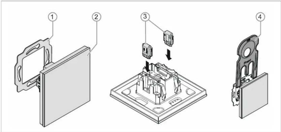
Fig. 1: Product overview
[1] Support ring [1]
[2] Flush-mounted insert with control element [2] (firmly installed unit)
[3] Clamps of removal protection [3] (optional)
[4] Removal tool [4] (optional)
4.2.2 Versions
The control elements are available in the 3 gang versions.
- Available are the preconfigured standard versions.
- Alternative to the standard versions, the control elements can be designed for the required functions via the ABB-tacteo configurator. The buttons can be additionally fitted with text if required.
The functionality, method of operation and installation/dismantling is identical for all models.

Fig. 2: Models of control elements (examples)
[1] Status indication for 3gang control elements
- Configurable: icon and text
[2] Status indication for 3gang control elements
- Configurable: icon and text
[3] Buttons for 3gang control elements
- Configurable: icon, text and function
4.2.3 Support rings
The support rings are partly different from country to country. The correct support ring is supplied according to country.
Country-specific support rings are for example:

Fig. 3: Country-specific support rings
[1] VDE Germany
[2] Switzerland / British standard (BS)
(The support ring for Switzerland is supplied without earth terminal)
[3] NEMA
[4] Italy
4.3 Functions
The following table provides an overview of the possible functions and applications of the device:
| Special features Function | |
| Orientation illumination (primary function)Configurable coversConfigurable icons and/or textFunction illuminationFreely programmableLED colour conceptProximity functionDay/night switchover of the LEDsIntegrated temperature sensorComprehensive application program | SwitchingDimmingBlindValue transmitterLight scene extension unitMultiple operationStep switchShort/long operationLogic functions(separate logic and value objects)Among others |
Table 1: Overview of functions
4.4 Scope of supply

Fig. 4: Scope of delivery
Included in the scope of delivery are:
- Support ring [1]
- Flush-mounted insert with control element [2] (firmly installed unit)
- Clamps of removal protection [3] (optional)
- Removal tool [4] (optional)

Note
- Additional information about possible device versions is available in the electronic catalogue (www.busch-jaeger-catalogue.com).
4.5 Overview of types
Models of control elements preconfigured or freely configurable
Article no. Product name
TA/U3.x.x-xx
Room outdoor sensor 3gang incl. BAU
- Square
- Vertical
- Horizontal
Table 2: Models of control elements preconfigured or freely configurable
5 Technical data
5.1 Technical data
| Designation Value | |
| Power supply: 24 V DC (via bus line) | |
| KNX connectionBus connecting terminal, screwless:Line type:Wire stripping: | 0.6 - 0.8 mmJ-Y(St)Y, 2 x 2 x 0.8 mm5 - 6 mm |
| Bus subscribers: 1 (≤12 mA) | |
| Temperature range: -5°C to +45°C | |
| Storage temperature: -20°C to +70°C | |
| Protection type: IP 20 |
Table 3: Technical data
5.2 Dimensional drawings

Fig. 5: Dimensions (all dimensions are in mm)
6 Connection, installation / mounting

Danger - Electric voltage!
Install the device only if you have the necessary electrical engineering knowledge and experience.
- Incorrect installation endangers your life and that of the users of the electrical system.
- Incorrect installation can cause serious damage to property, e.g. due to fire.
The minimum necessary expert knowledge and requirements for the installation are as follows:
- Apply the "five safety rules" (DIN VDE 0105, EN 50110):
- Disconnect
- Secure against being re-connected
- Ensure there is no voltage
- Connect to earth and short-circuit
-
Cover or barricade adjacent live parts.
-
Use suitable personal protective clothing.
- Use only suitable tools and measuring devices.
- Check the type of supply network (TN system, IT system, TT system) to secure the following power supply conditions (classic connection to ground, protective earthing, necessary additional measures, etc.).
- Observe the correct polarity.

Caution - Glass breakage!
The breakage of a glass plate could lead to the risk of injury.
Thr glass plate consists of high-quality safety glass. Yet breakage cannot be excluded.
- Avoid force being applied to the glass plate.
- Never reach into a broken glass with you bare hands.
6.1 Mounting

Caution! The device can sustain damage when coming into contact with hard objects!
The plastic parts of the device are sensitive.
– Pull the attachment off only with your hands.
- Do not lever parts off with screwdrivers or similar hard objects.
In Germany the flush-mounted insert must only be installed in flush-mounted boxes according to DIN 49073-1, Part 1, or suitable surface-mounted housings.
Different installation standards apply in other countries. These are to be taken into account when used in connection with a different support ring and flush-mounted box.
To install the device, perform the following steps:
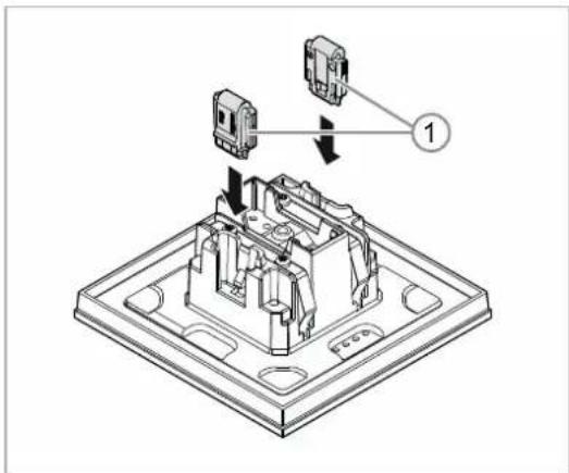
Fig. 6: Installation of the removal protection
Option
- Installing the removal protection.
- Push the removal protection into position by hand.
(The removal protection is not a component part of the device and is to be ordered separately.)

natural_image
Technical diagram of a mechanical assembly with a circular component and mounting bracket (no text or symbols)Fig. 7: Installation of the support ring
- Installing the support ring.

Fig. 8: Connection of the bus line
- Pull the bus line out of the flush-mounted box and connect the line to the bus connection terminal [1], see chapter 6.2 "Electrical connection" on page 25.
- Check that the polarity is correct!
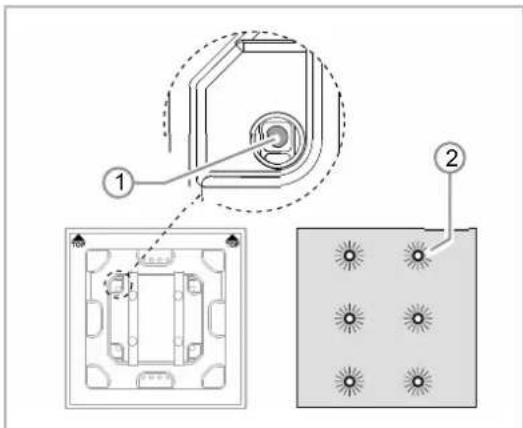
Fig. 9: Programming button
- To commission the device, see chapter 7 "Commissioning" on page 26.
- Programming is carried out via the programming button [1] on the rear of the device.
- Press the programming button [1].
- All LEDs [2] light up red.

natural_image
Diagram of a door or shelf assembly with a central box and directional arrow, no text or symbols presentFig. 10: Mounting devices
- Installing the device.
- Snap the device into the support ring by hand.
The device is now mounted.
6.2 Electrical connection

Fig. 11: Connection of bus coupler
Carry out the electrical connection according to the circuit diagram.
7 Commissioning
7.1 Software
To start the device a physical address must be assigned first. The physical address is assigned and the parameters are set with the Engineering Tool Software (ETS).

NOTE
The devices are products of the KNX system and meet KNX guidelines. Detailed expert knowledge by means of KNX training sessions for a better understanding is assumed.
7.1.1 Preparation
- Connect a PC to the KNX bus line via the KNX interface (e.g. via the commissioning interface / commissioning adapter 6149/21-500).
- The Engineering Tool Software must be installed on the PC (native application from ETS 4.0).
- Switch on the bus voltage.
7.1.2 Assigning a physical address

Fig. 12: Programming button
- Press the programming button [1].
- All LEDs [2] light up red.
7.1.3 Assigning the group address(es)
The group addresses are assigned in connection with the ETS.
7.1.4 Selecting the application program
Please contact our Internet support unit (www.BUSCH-JAEGER.com). The application is loaded into the device via the ETS.
7.1.5 Differentiating the application program
Various functions can be implemented via the ETS.
Detailed description of parameters, see chapter 11 "Description of application and parameters" on page 31 (only in languages DE, EN, ES, FR, IT and NL).
8 Updating options
A firmware update is carried out via the KNX bus by means of the ETS app "KNX Bus Update".

NOTE
The description of the update process can be downloaded via the electronic catalogue (www.busch-jaeger-catalogue.com). It is stored on the device page under category "Software".
9 Operation

Caution - Glass breakage!
The breakage of a glass plate could lead to the risk of injury.
Thr glass plate consists of high-quality safety glass. Yet breakage cannot be excluded.
- Avoid force being applied to the glass plate.
- Never reach into a broken glass with you bare hands.

Note
The buttons of the device can be individually configured prior to delivery according to requirement or wishes. The buttons of your device are probably different from the examples listed here.
The type of operation, however, is carried out in the same way.
Operation is carried out by touching the individual operating fields.
The function is specified via the assigned application / function and their parameter settings. Extensive functions are available for the operating fields.
Range of applications: see chapter 11 "Description of application and parameters" on page 31 (in languages DE, EN, ES, FR, IT, NL, PL and RU).
9.1 Colour concept

Fig. 13: Models of control elements (examples)
- The function icons [2] [4] have grey background.
- The function icons describe the function.
- The control icons [1] [3] (on the buttons) have a coloured background.
- The control icons "check" the function. The desired functions are carried out with the control icons.
- The control icons can also be fitted with additional text.
- The text has a grey background.
10 Maintenance
10.1 Maintenance-free device
The device is maintenance-free. In case of damage, e.g. during transport or storage), do not perform repairs. Once the device is opened, the warranty is void.
Access to the device must be guaranteed for operation, testing, inspection, maintenance and repairs (according to DIN VDE 0100-520).
10.2 Cleaning

Caution - Glass breakage!
The breakage of a glass plate could lead to the risk of injury.
Thr glass plate consists of high-quality safety glass. Yet breakage cannot be excluded.
- Avoid force being applied to the glass plate.
- Never reach into a broken glass with you bare hands.
Clean dirty devices with a soft dry cloth.
- If this is insufficient, the cloth can be moistened slightly with a soap solution.
11 Description of application and parameters
11.1 Application program
Available devices (Control elements):
- TB/U1.x.x-xx Control element 1gang incl. BAU
- TB/U2.x.x-xx Control element 2gang incl. BAU
- TB/U4.x.x-xx Control element 4gang incl. BAU
- TB/U6.x.x-xx Control element 6gang incl. BAU
- TB/U12.x.x-xx Control element 12gang incl. BAU
The following application programs are available:
| Application program |
| Control element xgang/1 |
The application program for the control elements contains the following applications:
| Parameter area KNX application | |
| Device settings: | Buzzer application |
| Proximity application | |
| Enable application | |
| Object during operation | |
| Primary function: 1-button switching | |
| Function block x: | 1-button switching |
| 1-button dimming | |
| 1-button blind | |
| 1-button short-long operation | |
| 1-button value transmitter | |
| 1-button value transmitter, 2 objects | |
| 1-button step switch | |
| 1-button multiple operation | |
| 1-button light scene extension unit with memory function | |
| 1-button operating mode, "Adjust RTC" | |
| 2-button switching | |
| 2-button dimming | |
| 2-button blind | |
| 2-button value transmitter | |
| 2-button value dimming sensor | |
| 2-button step switch |
Description of application and parameters
Application program
| LED function (button 1 / button 2) | |
| Temperature: Temperature sensor | |
| General functions: | Cyclic telegrams |
| Priority | |
| Logic gate | |
| Gate | |
| Staircase lighting | |
| Delay | |
| Min/max value transducer | |
| Light scene actuator |
Depending on the application selected, the Engineering Tool Software (ETS) shows different parameters and communication objects.
11.2 Overview of functions
| Application Parameters Options | ||
| Device settings — Acoustic feedback signal — Buzzer application | Selected feedback signal noise is on Clicking / | beeping |
| Acoustic feedback signal via object Deactivated / activated | ||
| Activation of the acoustic feedback signal with | On/off telegram | |
| Feedback signal after bus voltage recovery Deactivated / activated | ||
| Acoustic alarm via object Deactivated / activated | ||
| Alarm via the button Deactivated / activated | ||
| Ending the alarm automatically Deactivated / activated | ||
| Time for automatic ending of the alarm | 00:00:10 - 18:00:00 (hh:mm:ss) | |
| Time for automatic ending via object Deactivated / activated | ||
| Time for automatic ending at overwrite download | Deactivated / activated | |
| Device settings — Proximity — Proximity application | External proximity via object Deactivated / activated | |
| Automatic switchover time | 00:00:10 - 18:00:00 (hh:mm:ss) | |
| Brightness of the LED during blockage Off / dark / bright | ||
| LED colour in a blocked state Yellow - white | ||
| Internal proximity status via object Deactivated / activated | ||
| Device settings — Device enabling — Enable application | Enable with | On/off telegram |
| After bus voltage recovery the device is | Disabled / enabled | |
| Use of automatic enable/blockage | No / automatic enable / automatic blockage | |
| Automatic switchover time | 00:00:10 - 18:00:00 (hh:mm:ss) | |
| Switchover time via object | Deactivated / activated | |
| Overwrite switchover time at download | Deactivated / activated | |
| Brightness of the LED during blockage Off / dark / bright | ||
| LED colour in a blocked state Yellow - white | ||
| Device settings — In operation function — In operation object | Cycle time | 00:00:55 - 01:30:00 (hh:mm:ss) |
| Objects sends cyclic | On/off telegram | |
| Primary function — 1-button switching | Object type | 1 bit / 1 byte 0 - 100% / 1 byte 0 - 255 / Light scene number 1 - 64 / RTC operating mode switchover (1 byte) |
| Reaction on rising edge | Value 1 / value 2 / alternating value 1/ value 2 / deactivated | |
| Reaction on falling edge | Value 1 / value 2 / alternating value 1/ value 2 / deactivated | |
| Consider device enable | Deactivated / activated | |
| Value 1 | Setting dependent on object type | |
| Value 2 | Setting dependent on object type | |
| Function block x — 1-button switching | Reaction on rising edge | On / off / alternating on/of/ deactivated |
| Reaction on falling edge | On / off / alternating on/of/ deactivated | |
| Function block x — 1-button dimming | Duration of long operation 00.300 - 03.000 (ss.fff) | |
| Working mode of the buttons for switching | On / off / alternating on/of/ deactivated | |
| Working mode of the buttons for dimming Off / dark / bright | ||
| Function block x — 1-button blind | Duration of long operation 00.300 - 03.000 (ss.fff) | |
| Cycle time of the telegram repetition 00.100 - 05.000 (ss.fff) | ||
| Object type 1 bit / 1 byte 0-100% | ||
| Function switchover blinds/roller shutters Blinds / roller blinds | ||
| Value for position down (%) 0 - 100 (%) | ||
| Value for position up (%) 0 - 100 (%) | ||
| Value for slats position down (%) 0 - 100 (%) | ||
| Value for slats position down (%) 0 - 100 (%) | ||
| Function block x — 1-button short-long operation | Object type | 1 bit / 1 byte 0-100% / 1 byte 0-255 / 2 byte float / 2 byte signed / 2 byte unsigned / 4 byte float / 4 byte signed / 4 byte unsigned |
| Reaction on short operation | No reaction / value 1 / value 2 / alternating value 1 / value 2 | |
| Reaction on long operation | No reaction / value 1 / value 2 / alternating value 1 / value 2 | |
| Duration of long operation 00.300 - 03.000 (ss.fff) | ||
| Value 1 for short operation | Setting dependent on object type | |
| Value 2 for short operation | Setting dependent on object type | |
| Value 1 for long operation | Setting dependent on object type | |
| Value 2 for long operation | Setting dependent on object type | |
| Function block x — 1-button value transmitter | Object type | 1 bit / 1 byte 0-100% / 1 byte 0-255 / 2 byte float / 2 byte signed / 2 byte unsigned / 4 byte float / 4 byte signed / 4 byte unsigned |
| Reaction on rising edge | No reaction / value 1 / value 2 / alternating value 1 / value 2 | |
| Reaction on falling edge | No reaction / value 1 / value 2 / alternating value 1 / value 2 | |
| Function block x — 1-button value transmitter, 2 objects | Object type for rising edge | 1 bit / 1 byte 0-100% / 1 byte 0-255 / 2 byte float / 2 byte signed / 2 byte unsigned / 4 byte float / 4 byte signed / 4 byte unsigned |
| Object type for falling edge | 1 bit / 1 byte 0-100% / 1 byte 0-255 / 2 byte float / 2 byte signed / 2 byte unsigned / 4 byte float / 4 byte signed / 4 byte unsigned | |
| Reaction on rising edge | No reaction / value 1 / value 2 / alternating value 1/ value 2 | |
| Reaction on falling edge | No reaction / value 1 / value 2 / alternating value 1/ value 2 | |
| Value 1 for rising edge | Setting dependent on object type | |
| Value 2 for rising edge | Setting dependent on object type | |
| Value 1 for falling edge | Setting dependent on object type | |
| Value 2 for falling edge | Setting dependent on object type | |
| Function block x — 1-button step switch | Number of objects 1 - 5 | |
| Evaluation period 02.000 - 05.000 (ss.fff) | ||
| Duration of long operation 00.300 - 02.500 (ss.fff) | ||
| Sending of objects | At operation / at value change | |
| Object values Normal / inverse | ||
| Bit pattern of the object values x off n / 1 off n | ||
| Function block x — 1-button multiple operation | Number of objects or operations 1 - 5 | |
| Evaluation period 01.000 - 05.000 (ss.fff) | ||
| Object type for object x | 1 bit / 1 byte 0-100% / 1 byte 0-255 / 2 byte float / 2 byte signed / 2 byte unsigned / 4 byte float / 4 byte signed / 4 byte unsigned | |
| Function for object type 1-bit for object x | Send value / alternating on/off | |
| Value for object x | Setting dependent on object type | |
| Function block x — 1-button light scene extension unit with memory function | Duration of long operation 00.300 - 10.000 (ss.fff) | |
| Light scene memory function Deactivated / activated | ||
| Number of light scene 1 - 64 | ||
| Function block x — 1-button operating mode, "Adjust RTC" | Object type for output 1 bit / 1 byte | |
| Working mode | Auto / comfort / standby / ECO / frost/heat protection | |
| Enable object Deactivated / activated | ||
| Object value enable object Normal / inverse | ||
| Enable object after return of voltage Disabled / enabled | ||
| Send comfort object Deactivated / activated | ||
| Send Eco object Deactivated / activated | ||
| Send frost object Deactivated / activated | ||
| Function block x —2-button switching | Working mode of the buttons for switching | 1st button on - 2nd button off/ 1st button off - 2nd buttonon / alternating on/off |
| Function block x —2-button dimming | Duration of long operation 00.300 - 03.000 (ss.fff) | |
| Manner of dimming | Start-stop dimming / step-wise dimming | |
| Step size for step-wise dimming (%) | 1.56 / 3.13 / 6.25 / 12.5 / 25 /50 | |
| Dimming function | Short operation dimming,long operation switching /short operation switching,long operation dimming | |
| Working mode of the buttons for switching | 1st button on - 2nd button off/ 1st button off - 2nd buttonon / alternating on/off | |
| Working mode of the buttons for dimming | 1st button brighter, 2ndbutton darker / 1st buttondarker - 2nd button brighter | |
| Dimming stop telegram | Dimming stop is not sent /dimming stop is sent | |
| Cyclic sending of the dimming telegrams | Deactivated / activated | |
| Duration of telegram repetition 00.100 - 05.000 (ss.fff) | ||
| Function block x —2-button blind | Duration of long operation 00.300 - 03.000 (ss.fff) | |
| Object type 1 bit / 1 byte 0-100% | ||
| Working mode of the buttons | 1st button up / 2nd buttondown /1st button down - 2nd buttonup | |
| Value for position down (%) 0 - 100 (%) | ||
| Value for position up (%) 0 - 100 (%) | ||
| Value for slats position down (%) 0 - 100 (%) | ||
| Value for slats position down (%) 0 - 100 (%) | ||
| Function block x —2-button valuetransmitter | Object type | 1 bit / 1 byte 0-100% / 1 byte0-255 / 2 byte float / 2 bytesigned / 2 byte unsigned / 4byte float / 4 byte signed / 4byte unsigned |
| Working mode of the buttons | 1st button value 1 - 2ndbutton value 2 / 1st buttonvalue 2 - 2nd button value 1 /alternating value1/value 2 | |
| Value 1 | Setting dependent on objecttype | |
| Value 2 | Setting dependent on object type | |
| Function block x — 2-button value dimming sensor | Object type | 1 byte 0-100% / 1 byte 0-255 |
| Step width (%) | Setting dependent on object type | |
| Working mode of the buttons | 1st button brighter, 2nd button darker / 1st button darker - 2nd button brighter | |
| Function block x — 2-button step switch | Number of objects 1 - 5 | |
| Evaluation period 01.000 - 05.000 (ss.fff) | ||
| Working mode of the buttons | 1st button down / 2nd button up / 1st button up - 2nd button down | |
| Sending of objects | At operation / at value change | |
| Object values Normal / inverse | ||
| Bit pattern of the object values x off n / 1 off n | ||
| Function block x — LED function | Operating mode | Status illumination / function illumination |
| Object type for status object 1 bit / 1 byte 0-100% | ||
| Brightness of the colours Dark / bright | ||
| Colour for Off Off / yellow - white | ||
| Colour for On Off / yellow - white | ||
| Colour for Zone 1 (corresponds to 0%) Off / yellow - white | ||
| Colour for Zone 2 (starting at 1%) Off / yellow - white | ||
| Threshold between Zone 2 and 3 (%) 1 - 98 | ||
| Colour for Zone 3 Off / yellow - white | ||
| Threshold between Zone 3 and 4 (%) 2 - 99 | ||
| Colour for Zone 4 (up to 99%) Off / yellow - white | ||
| Colour for Zone 5 (corresponds to 100%) Off / yellow - white | ||
| Colour of function illumination Off / yellow - white | ||
| Day/Night mode Deactivated / activated | ||
| Light scene memory function | Deactivated / activated | |
| Alarm function | Deactivated / activated | |
| Temperature — Temperature sensor | Send measured values | Only cyclic / cyclic and at a value change |
| Cycle time for sending of the actual temperature | 00:00:25 - 01:30:00 (hh:mm:ss) | |
| Temperature difference for sending within the cycle time *0.1 K | 1 - 255 | |
| Offset of the temperature sensor (x 0.1°C) | -127 - 127 | |
| Overwriting internal object | No / yes | |
| General functions — | Channel name | |
| channel x —Cyclic telegram | Object type | 1 bit switching / 1 bit alarm /1 byte 0-100% / 1 byte 0-255/ 2 byte float / 2 byte signed /2 byte unsigned / 4 byte float/ 4 byte signed / 4 byteunsigned |
| Cycle time | 00:00:55 - 01:30:00(hh:mm:ss) | |
| Enable object Deactivated / activated | ||
| Object value enable object Normal / inverse | ||
| Enable object after return of voltage Disabled / enabled | ||
| Cyclic sending | Always activated / activatedat specified value / activatedexcept specified value | |
| Value for cyclic sending | Setting dependent on objecttype | |
| General functions —channel x —Priority | Channel name | |
| General functions —channel x —Logic gate | Channel name | |
| Logical function | AND / OR / XOR / XNOR /NAND / NOR | |
| Number of input objects 1 - 10 | ||
| Object type input x 1 bit / 1 byte | ||
| Initial value input x | Initialised with 0 /Initialised with 1 | |
| Logic input x Normal / inverse | ||
| Object type output 1 bit / 1 byte | ||
| Send output object | At each incoming telegram /at each change of outputobject | |
| Value of the output object for logic true | Output is set on 1 / definedvia output default value true | |
| Output default value true True = 0 / true = 1 | ||
| Output default value true 0 - 255 | ||
| Value of the output object for logic untrue | Output is set on 0 / definedvia output default valueuntrue | |
| Output default value untrue Untrue = 0 / untrue = 1 | ||
| Output default value untrue 0 - 255 | ||
| General functions —channel x —Gate | Channel name | |
| Object type | 1 bit switching / 1 bit moving/ 1 bit stop/adjusting / 2 bitpriority / 4 bit relativedimming 1 byte 0-100% / 1byte 0-255 / 2 byte float / 2byte signed / 2 byteunsigned / 3 byte time / 3byte date / 4 byte float / 4byte signed / 4 byteunsigned / not allocated | |
Description of application and parameters
Overview of functions
| Filter function | Deactivated / on filter out / off filter out | |
| Data flow direction | Input in direction of output / output in direction of input / in both directions | |
| Enable object Deactivated / activated | ||
| Object value enable object Normal / inverse | ||
| Enable object after return of voltage Disabled / enabled | ||
| Save input signal Deactivated / activated | ||
| General functions — channel x — Staircase lighting | Channel name | |
| Object type/number | One 1-bit object for the input and output / two 1-bit objects for the input and output / two 1-byte objects for the input and output | |
| Switch-off delay | 00:00:10 - 01:30:00 (hh:mm:ss) | |
| Retriggering Deactivated / activated | ||
| Switch-off pre-warning Deactivated / activated | ||
| Time for switch-off pre-warning (s) 1 - 5400 | ||
| Value for switch-off prewarning (%) 1 - 100 (%) | ||
| Overwrite at switch-off delay and switch-off prewarning time during download | Deactivated / activated | |
| General functions — channel x — Delay | Channel name | |
| Object type | 1 bit switching / 1 bit moving / 1 bit stop/adjusting / 1 byte 0-100% / 1 byte 0-255 / 2 byte float / 2 byte signed / 2 byte unsigned / 4 byte float / 4 byte signed / 4 byte unsigned | |
| Delay time | 00:00:01.000-01:00:00.000 (hh:mm:ss.fff) | |
| Retriggering Deactivated / activated | ||
| Filter active Deactivated / activated | ||
| Filter function | Filter value is delayed, others are sent direct / filter value is delayed, others are suppressed / filter value is sent direct, others are delayed / filter value is suppressed, others are delayed | |
| Filter value | Setting dependent on object type | |
| Overwrite delay time during download Deactivated / activated | ||
| General functions — | Channel name | |
Description of application and parameters
Overview of functions
| channel x —Min/max value transducer | Object type | 1 byte 0-100% / 1 byte 0-255 / 2 byte float / 2 byte signed / 2 byte unsigned / 4 byte float / 4 byte signed / 4 byte unsigned |
| Number of input objects 1 - 8 | ||
| Output sends | At each input assignment / when the output object is changed | |
| Output object | Assumes the largest input value / assumes the smallest input value / assumes the input average | |
| General functions — channel x —Light scene actuator | Channel name | |
| Number of scenes 1 - 8 | ||
| Number of actuator groups 1 - 8 | ||
| Duration of telegram delay 00.100 - 10.000 (s$.fff) | ||
| Overwrite scenes at download Deactivated / activated | ||
| Object type actuator group x | Light scene number / 1 bit switching / 1 bit blind / 1 byte 0-100% / temperature | |
| Scene number 1 - 64 | ||
| Scene can be saved Deactivated / activated | ||
| Actuator group x Deactivated / activated | ||
| Number of light scene 1 - 64 | ||
| Value Off / on | ||
| Value Up / down | ||
| Value (%) 0 - 100 | ||
| Temperature -33.5 - 93.5 |
Table 4: Overview of applications and functions
11.3 Application "Device settings"
11.3.1 Acoustic feedback signal - Application
| Options: InactiveBuzzer application | |
- Inactive:
– The application is not active. - Buzzer application:
– The application is active.
The application is used to specify whether an acoustic signal sounds when a button is pressed. This signal can be adapted individually after the activation.
The following communication objects are available:
- "BUZ: object activation of acoustic feedback signal"
- "BUZ: triggering an alarm"
- "BUZ: time for automatic deactivation of the alarm"
The communication objects are enabled via the associated parameters.
Note
The following parameters can only be adjusted when the function "Acoustic feedback signal" is set on "Buzzer application".
The parameters for application "Acoustic feedback signal" can be called up via general parameters.
11.3.1.1 Selected feedback signal noise is on
| Options: ClickBeeping | |
- Clicking:
- "Clicking" sounds at the press of the buttons.
- Beeping:
- "Beeping" sounds at the press of the buttons.
The parameter us used to specify the type of acoustic signal for the feedback signal noise.
11.3.1.2 Acoustic feedback signal via object
| Options: Deactivated Activated | |
- Deactivated:
- The communication object is not enabled.
- Activated:
- The communication object is enabled.
A 1-bit communication object "BUZ: object activation of acoustic feedback signal" can be enabled with this parameter. The further differentiation is carried out via the parameter that is available after enabling.
11.3.1.3 Activation of the acoustic feedback signal with
| Options: On telegramOff telegram | |
- ON telegram:
- Activation via On telegram.
- Off telegram:
- Activation via Off telegram.
The parameter is used to specify whether the acoustic feedback signal is activated via the input object at the receipt of an On or an Off telegram.
Note
The parameter can only be set when parameter "Acoustic feedback signal via object" or parameter "Acoustic alarm via object" is activated.
11.3.1.4 Feedback signal after bus voltage recovery
| Options: Deactivated Activated | |
- Deactivated:
- Automatic deactivation after bus voltage recovery.
- Activated:
– Automatic activation after bus voltage recovery.
If the "Acoustic feedback signal via object" is to start automatically after the bus voltage recovery, the parameter "Feedback signal after bus voltage recovery" must be set on "activated". If "deactivated has been selected, the "Acoustic feedback signal via object" does not start after bus voltage recovery.

Note
The parameter can only be set when parameter "Acoustic feedback signal via object" is activated.
11.3.1.5 Acoustic alarm via object
| Options: Deactivated Activated | |
- Deactivated:
– The communication object is not enabled. - Activated:
- The communication object is enabled.
A 1-byte communication object "BUZ: trigger alarm" can be enabled with this parameter. The further differentiation is carried out via the parameter that is available after enabling.
The alarm function can, for example, display a wind alarm or an open door when the user wants to lower a blind or a roller blind.
11.3.1.6 Activation of the acoustic feedback signal with
| Options: On telegramOff telegram | |
- ON telegram:
- Activation via On telegram.
- Off telegram:
- Activation via Off telegram.
The parameter is used to specify whether the acoustic feedback signal is activated via the input object at the receipt of an On or an Off telegram.

Note
The parameter can only be set when parameter "Acoustic feedback signal via object" or parameter "Acoustic alarm via object" is activated.
11.3.1.7 Alarm via the button
| Options: Deactivated Activated | |
- Deactivated:
- The pending alarm can not be deactivated with a press of the button.
- Activated:
- The pending alarm can be deactivated with a press of the button.

Note
The parameter can only be set when parameter "Acoustic alarm via object" is activated.
11.3.1.8 Ending the alarm automatically
| Options: Deactivated Activated | |
- Deactivated:
- The alarm is not switched off automatically.
- Activated:
- The alarm is switched off automatically at an adjustable time.
By activating the parameter the alarm is automatically switched off after a parameterised time. The switch-off time is set via parameter "Time for automatic ending of the alarm".
The further differentiation is carried out via the parameter that is available after enabling.

Note
The parameter can only be set when parameter "Acoustic alarm via object" is activated.
11.3.1.9 Time for automatic ending of the alarm
| Options: Setting option from 00:00:10 to 18:00:00 (hh:mm:ss) |
The set value defines the time for the automatic ending of the pending alarm.
The further differentiation is carried out via the parameter that is available after enabling.
Note
The parameter can only be set when parameters "Acoustic alarm via object" and "Ending the alarm automatically" are activated.
11.3.1.10 Time for automatic ending via object
| Options: Deactivated Activated | |
- Deactivated:
- The communication object is not enabled.
- Activated:
– The communication object is enabled.
A 2-byte communication object "BUZ: time for automatic activation of the alarm" can be enabled with this parameter. The further differentiation is carried out via the parameter that is available after enabling.
Note
The parameter can only be set when parameters "Acoustic alarm via object" and "Ending the alarm automatically" are activated.
11.3.1.11 Time for automatic ending at overwrite download
| Options: Deactivated Activated | |
- Deactivated:
– Time for automatic ending is not overwritten during a download of the application. - Activated:
– Time for automatic ending is overwritten during a download of the application.
The parameter can be used to specify whether the data changed via communication object "BUZ: time for automatic deactivation of the alarm" are to be overwritten during the download or the times should be retained.

Note
The parameter can only be adjusted if the following parameters are activated:
- "Acoustic alarm via object"
- "Ending the alarm automatically"
- "Time for automatic ending via object"
11.3.2 Proximity - Application
| Options: InactiveProximity application | |
- Inactive:
– Application is not active. - Proximity application:
– Application is active.
The Application is used to specify whether it is recognized when the user approaches the device. The application can be used, for example, that the display and LEDs first switch on when the user is located in front of the device.
The following communication objects are available:
- "NARX: proximity"
- "NARX: internal proximity status"
The communication objects are enabled via the associated parameters.
Note
The following parameters can only be adjusted when the function "Proximity" is set on "Proximity application".
The parameters for application "Proximity" can be called up via general parameters.
11.3.2.1 External proximity via object
| Options: Deactivated Activated | |
- Deactivated:
- The communication object is not enabled.
- Activated:
- The communication object is enabled.
A 1-bit communication object "NARX: proximity" can be enabled with this parameter. If an On telegram is received via this object, the proximity function is active. If an Off telegram is received via this object, the proximity function is disabled.
11.3.2.2 Automatic switchover time
| Options: Setting option from 00:00:10 to 18:00:00 (hh:mm:ss) |
The switching on or switchover always occurs immediately the user has approached the device. The switching off or switchover can be delayed via parameter "Automatic switchover time". In this way, for example, the display stays switched on for a while longer although the user has just moved away from the device.

Note
The parameter can only be set when parameter "External proximity via object" is deactivated.
11.3.2.3 Brightness of the LED during blockage
| Options: Off | |
| Dark | |
| Bright |
Off:
- The LED does not light up at blockage.
- Dark :
- The LED lights up dark at blockage.
- Bright:
- The LED lights up bright at blockage.
The parameter is used to specify whether or in which brightness the LED lights up when the device is blocked.
11.3.2.4 LED colour in a blocked state
| Options: Yellow | |
| Orange | |
| Red | |
| Violet | |
| Blue | |
| Green | |
| White |
- Yellow - white:
- The LED lights up in the specified colour during blockage.
The parameter is used to specify the colour the LED lights up in when the device is blocked.

Note
The parameter is only adjustable if the "Brightness of LED during blockage" parameter is set on "dark" or "bright".
11.3.2.5 Internal proximity status via object
| Options: Deactivated Activated | |
- Deactivated:
- The communication object is not enabled.
- Activated:
- The communication object is enabled.
A 1-bit communication object "NARX: internal proximity status" can be enabled with this parameter. A telegram is ent on the bus via the enabled object when the user approaches the device.
11.3.3 Device enable - Application
| Options: InactiveEnable application | |
- Inactive:
– Application is not active. - Enable application:
– Application is active.
If the application is activated the device can be blocked temporarily via the 1-bit communication object "EF: enable". No telegrams are sent on the bus via the communication object of the device during a blockage. It can be enabled via an On or an Off telegram.
The following communication objects are available:
- "EF: enable"
- "EF: automatic switchover time"
The communication objects are enabled via the associated parameters.

Note
The following parameters can only be adjusted when the function "Device enable" is set on "Enable application".
The parameters for application "Device enable" can be called up via general parameters.
11.3.3.1 Enable with
| Options: On telegramOff telegram | |
- ON telegram:
– Devices are enabled via an On telegram. - Off telegram:
– Devices are enabled via an Off telegram.
The device is normally enabled with the receipt of an ON telegram via 1-bit communication object "EF: enabled" and blocked with an OFF telegram. The parameter can invert this behaviour.
11.3.3.2 After bus voltage recovery the device is
| Options: BlockedEnabled | |
- Blocked:
- The enable object has value"1" after bus voltage recovery.
- Enabled:
- The enable object has value "0" after bus voltage recovery.
The parameter serves to ensure that a defined behaviour is present on communication object "EF: enable" after a return of bus voltage.
11.3.3.3 Use of automatic enable/blockage
| Options: No | |
| Automatic enable | |
| Automatic blockage |
No:
- No automatic enable or blockage of the device.
- Automatic enable:
- Function "Automatic enable" is active.
- Automatic blockage:
- Function "Automatic blockage" ia active.
The parameter can be used to automatically enable or automatically block the device.
11.3.3.4 Automatic switchover time
| Options: Setting option from 00:00:10 to 18:00:00 (hh:mm:ss) |
The switching on or switchover always occurs immediately the user has approached the device.
The switching off or switchover can be delayed via the parameter. In this way, for example, the display stays switched on for a while longer although the user has just moved away from the device.

Note
This parameter can only be adjusted when the "Use of automatic enable/blockage" parameter is set on "Automatic enable" or "Automatic blockage".
11.3.3.5 Switchover time via object
| Options: Deactivated Activated | |
- Deactivated:
- The communication object is not enabled.
- Activated:
– The communication object is enabled.
A 2-byte communication object "EF: automatic switchover time" can be enabled with this parameter. The time can then be adjusted via the KNX bus.

Note
This parameter can only be adjusted when the "Use of automatic enable/blockage" parameter is set on "Automatic enable" or "Automatic blockage".
11.3.3.6 Overwrite switchover time at download
| Options: Deactivated Activated | |
- Deactivated:
- The switchover time is not overwritten during a download of the application.
- Activated:
- The switchover time is overwritten during a download of the application.
The parameter can be used to specify whether the data changed via communication object "EF: automatic switchover time" are to be overwritten during the download or the times should be retained.
Note
This parameter can only be adjusted when the "Use of automatic enable/blockage" parameter is set on "Automatic enable" or "Automatic blockage".
11.3.3.7 Brightness of the LED during blockage
| Options: Off | |
| Dark | |
| Bright |
Off:
- The LED does not light up at blockage.
- Dark :
- The LED lights up dark at blockage.
- Bright:
- The LED lights up bright at blockage.
The parameter is used to specify whether or in which brightness the LED lights up when the device is blocked.
11.3.3.8 LED colour in a blocked state
| Options: Yellow | |
| Orange | |
| Red | |
| Violet | |
| Blue | |
| Green | |
| White |
- Yellow - white:
- The LED lights up in the specified colour during blockage.
The parameter is used to specify the colour the LED lights up in when the device is blocked.

Note
The parameter is only adjustable if the "Brightness of LED during blockage" parameter is set on "dark" or "bright".
11.3.4 During operation function - Application
| Options: InactiveObject during operation | |
- Inactive:
– Application is not active. - Object during operation:
– Application is active.
The application makes monitoring of the device possible. A 1-bit telegram for further evaluation is made cyclically available to the KNX bus via communication object "HB: output". This, for example, allows monitoring of the device on a visualization. When the device is removed, it does not send a cyclic telegram and a fault message appears on the visualization.
The following communication object is available:
- "HB: output"

Note
The following parameters can only be adjusted when the function "Function during operation" is set on "Object during operation".
The parameters for application "Function during operation" can be called up via general parameters.
11.3.4.1 Cycle time
| Options: Setting option from 00:00:55 to 01:30:00 (hh:mm:ss) |
The telegrams of the object during operation are sent cyclic on the bus.
The parameter specifies the time interval from which a new sending of the telegrams occurs.
11.3.4.2 Objects sends cyclic
| Options: On telegramOff telegram | |
- ON telegram:
- Object during operation sends an On telegram.
- Off telegram:
- Object during operation sends an Off telegram.
The parameter is used to specify whether an Off or an On telegram is sent cyclic on the KNX bus via communication object "HB: output" during the parameterized time.
11.4 Application "Primary function"
11.4.1 Primary function - Application
| Options: Inactive1-button switching | |
- Inactive:
– Application is not active. - 1-button switching:
– Application is active.
The application is used to fix the primary function of the device. The primary function is the first function of the device that is carried out when the user presses button 1 or 2. The primary function should be a function that the user would use when entering the room for example (e.g. "switching the ceiling light").
When the application is active, a switching telegram is sent when the button is pressed or released.
The following communication object is available:
- "PF: switching"
Note
The following parameters can only be adjusted when the function "Primary function" is set on "1-button switching".
The parameters for "Primary function" can be called up via general parameters.
11.4.1.1 Object type
| Options: 1 bit | |
| 1 byte 0 - 100% | |
| 1 byte 0 - 255 | |
| Light scene number 1-64 | |
| RTC operating mode switchover (1 byte) | |
- 1 bit:
- The value is sent as 1-bit switching commands (0 or 1), e.g. On/Off, enabled/blocked, true/untrue.
- 1 byte 0 - 100%:
- The value is sent as 1-byte value without a sign (percentage value). (0 = 0%, 255 = 100%)
- 1 byte 0 - 255:
- The value is sent as 1-byte value without a sign. Any value 0 - 255.
• Light scene number 1 - 64:
- Value is sent as scene number or scene control (1 - 64).
- RTC operating mode switchover (1 byte):
- Value is sent as 1-byte value for the RTC operating mode switchover, e.g. auto, comfort, ECO), when the room temperature controller has been linked.
The "1-button value switching" application makes communication object "PF: switching" available for both input and output. The bit size of the communication object is fixed via the "Object type" parameter. For the most diverse applications, the size of the communication object can be adapted via "Object type".
11.4.1.2 Reaction on rising edge
| Options: Value 1 | |
| Value 2 | |
| Alternating value1/value2 | |
| Deactivated |
- Value 1:
- Value 1 is sent at the press of the button (at rising edge).
- Value 2: - Value 2 is sent at the press of the button (at rising edge).
- Alternating value 1/value 2: - Value 1 and value 2 are sent alternately at the press of the button.
- Deactivated: - No telegram is sent at the press of the button.
Application "1-button value switching" can differentiate between the press and the releasing of the button. A press is defined as "Rising edge" and the releasing as "Falling edge".
The parameter is used to specify whether a telegram with value 1 or value 2 is sent on the bus at a rising edge via communication object "PF: switching". A further option can be specified as to whether the telegrams are sent alternately. This means that after value 1 has been sent, value 2 is sent at a renewed press of the button. After it is pressed again, value 1 is again sent out.

Note
Parameter "Value 1" and "Value 2" is used to specify the values that are to be sent.
11.4.1.3 Reaction on falling edge
| Options: Value 1 | |
| Value 2 | |
| Alternating value1/value2 | |
| Deactivated |
- Value 1:
- Value 1 is sent when the button is released (at falling edge).
- Value 2:
- Value 2 is sent when the button is released (at falling edge).
- Alternating value 1/value 2:
- Value 1 and value 2 are sent alternately when the button is released.
- Deactivated:
- No telegram is sent when the button is released.
Application "1-button value switching" can differentiate between the press and the releasing of a button. A press is defined as "Rising edge" and the releasing as "Falling edge".
The parameter is used to specify whether a telegram with value 1 or value 2 is sent on the bus at a falling edge via communication object "PF: switching". A further option can be specified as to whether the telegrams are sent alternately. This means that after value 1 has been sent, value 2 is sent at a renewed release of the button. After it is released again, value 1 is again sent out.
Note
Parameter "Value 1" and "Value 2" is used to specify the values that are to be sent.
11.4.1.4 Consider device enable
| Options: Deactivated Activated | |
- Deactivated:
- Device enable is not taken into account for the primary function.
- Activated:
- Device enable is taken into account for the primary function.
The primary function can be included in the device enable via the parameter. The parameter must be activated for this. Operating the device via the primary would then not be possible in a disabled state.
When the parameter is deactivated the device enable or blockage has an effect only on the individual buttons.
11.4.1.5 Value 1/Value 2
The possible options depend on parameter "Object type".
Options for selection "1 bit":
| Options: OffOne | |
Options for selection "1 byte 0-100%":
| Options: Setting option from 0 to 100 (%) |
Options for selection "1 byte 0-255":
| Options: Setting option from 0 | to 255 |
Options for selection "Light scene number (1-64)":
| Options: Setting option from 1 | to 64 |
Options for selection "RTC operating mode switchover (1 byte)":
| Options: Auto | |
| Comfort | |
| Standby | |
| ECO | |
| Frost/heat protection |
The parameter is used to set value 1 that is sent at a press of the button.

Note
Parameter can only be set if the "Reaction at rising/falling edge" parameter is set on "Value 1" or "Alternating Value1/Value2".
11.4.1.6 Value 2
The possible options depend on parameter "Object type".
Options for selection "1 bit":
| Options: OffOne | |
Options for selection "1 byte 0-100%":
| Options: Setting option from 0 to 100 (%) |
Options for selection "1 byte 0-255":
| Options: Setting option from 0 | to 255 |
Options for selection "Light scene number (1-64)":
| Options: Setting option from 1 | to 64 |
Options for selection "RTC operating mode switchover (1 byte)":
| Options: Auto | |
| Comfort | |
| Standby | |
| ECO | |
| Frost/heat protection |
The parameter is used to set value 2 that is sent at a press of the button.

Note
Parameter can only be set if the "Reaction at rising/falling edge" parameter is set on "Value 2" or "Alternating Value1/Value2".
11.5 Application "Function block x"
Depending on the device type, from one to six function blocks with buttons and LED applications for up to 12 buttons are available:
- Function block 1: Settings for buttons 1 and 2. For a 1gang device only one function block with a 1-button application is available.
- Function block 2: Settings for buttons 3 and 4.
- Function block 3: Settings for buttons 5 and 6.
- Function block 4: Settings for buttons 7 and 8.
- Function block 5: Settings for buttons 9 and 10.
- Function block 6: Settings for buttons 11 and 12.
11.5.1 Function block x - Application
Button applications:
| Options: 1-button switching | |
| 1-button dimming | |
| 1-button blind | |
| 1-button short-long operation | |
| 1-button value transmitter | |
| 1-button value transmitter, 2 objects | |
| 1-button step switch | |
| 1-button multiple operation | |
| 1-button light scene extension unit with memory function | |
| 1-button operating mode, "Adjust RTC" | |
| 2-button switching | |
| 2-button dimming | |
| 2-button blind | |
| 2-button value transmitter | |
| 2-button value dimming sensor | |
| 2-button step switch | |
| Inactive | |

Note
The following parameters can only be adjusted when the corresponding application (see above) is selected.
- 1-button switching:
- The application makes it possible to switch a light via a button. Additional information, See "Application - 1-button switching" on page 64.
- 1-button dimming:
- The application makes it possible to dim and switch a light via a button. Additional information, See "Application - 1-button dimming" on page 66.
- 1-button blind:
- The application makes it possible to control blinds and roller blinds via a button. The length of press of the button can be set for different movement commands. Additional information, See "Application - 1-button blind" on page 68.
- 1-button short-long operation:
- The application can be used to set the value for long and short operations. Additional information, See "Application - 1-button short-long operation" on page 73.
- 1-button value transmitter:
- At a press and release of the button the application makes it possible to send different, preset values via a joint communication object. Additional information, See "Application - 1-button value transmitter" on page 79.
- 1-button value transmitter, 2 objects:
- At a press and release of the button the application makes it possible to send different, preset values via separate communication objects. Additional information, See "Application - 1-button value transmitter, 2 objects" on page 84.
- 1-button step switch:
- Up to five switching levels can be activated for a button via the application. The switching levels of the first button can be combined with the switching levels of the second button of a function block. Additional information, See "Application - 1-button step switch" on page 90.
- 1-button multiple operation:
- The application is used to create from one up to five button operations. Different bit values can be sent for each single and multiple press of the button. Additional information, See "Application - 1-button multiple operation" on page 94.
- 1-button light scene extension unit with memory function:
- The application can be used to call up and save one of 64 possible light scenes with a press of the button. Additional information, See "Application - 1-button light scene extension unit with memory function" on page 99.
- 1-button operating mode, "Adjust RTC".
- The operating mode of linked room temperature controllers can be switched over via the application with a press of the button. Additional information, See "Application - 1-button operating mode "Adjust RTC" on page 101.
- 2-button switching:
- The application makes it possible to switch a light via a button pair. Additional information, See "Application - 2-button switching" on page 108.
- 2-button dimming:
- The application makes it possible to dim and switch a light via a button pair. Additional information, See "Application - 2-button dimming" on page 109.
- 2-button blind:
- The application makes it possible to control blinds and roller blinds via a button pair. Additional information, See "Application - 2-button blind" on page 116.
- 2-button value transmitter:
- The application makes it possible to send two preset values with the same bit size with a button pair via a joint communication object. Additional information, See "Application - 2-button value transmitter" on page 120.
- 2-button value dimming sensor:
- The application makes it possible to dim the light brighter and darker via a button pair. The dimming values are sent via a joint communication object. Additional information, See "Application - 2-button value dimming sensor" on page 124.
- 2-button step switch:
- Up to five switching levels can be activated for a button pair via the application. One button is used to switch the steps up and the other button to switch them down. Additional information, See "Application - 2-button step switch" on page 126.
- Inactive:
- No applications are enabled.
11.5.2 Application - 1-button switching
The application makes it possible to switch a light via a button.
The following communication object is available:
- "Sx: switching"
The application can differentiate between the press and the releasing of a button. When actuated and released a switching telegram is sent out each time.
In each case, the application makes a separate set of parameters and communication objects available in function block x for both buttons. The second button of each function block can be occupied with an additional button function.

Note
The parameters for application "1-button switching" can be called up via general parameters.
Note
The number (S1 - Sx) of the object depends on the function block and the button number.
11.5.2.1 Reaction on rising edge
| Options: Deactivated | |
| Off | |
| On | |
| Alternating on/off |
- Deactivated:
- No telegram is sent at the press of the button.
Off:
- The "Off" telegram is sent at the press of the button (at rising edge).
- O n :
- The "On" telegram is sent at the press of the button (at rising edge).
- Alternating on/off:
- "On" and "Off" are sent alternately at the press of the button.
Application "1-button value switching" can differentiate between the press and the releasing of the button. A press is defined as "Rising edge" and the releasing as "Falling edge".
The parameter is used to specify whether an On or Off telegram is sent on the bus at a rising edge via the 1-bit communication object "Sx: switching". A further option can be specified as to whether the switching telegrams are sent alternately. This means that after "On" is sent, "Off" is sent at a renewed press of the button. After it is pressed again, "On" is sent.
11.5.2.2 Reaction on falling edge
| Options: Deactivated | |
| Off | |
| On | |
| Alternating on/off |
- Deactivated:
- No telegram is sent when the button is released.
Off:
- The "Off" telegram is sent when the button is released (at falling edge).
- O n :
- The "On" telegram is sent when the button is released (at falling edge).
- Alternating on/off:
- "On" and "Off" are sent alternately when the button is released.
Application "1-button value switching" can differentiate between the press and the releasing of the button. A press is defined as "Rising edge" and the releasing as "Falling edge".
The parameter is used to specify whether an On or Off telegram is sent on the bus at a falling edge via the 1-bit communication object "Sx: switching". A further option can be specified as to whether the switching telegrams are sent alternately. This means that after value "On" has been sent, "Off" is sent at a renewed release of the button. After it is released again, "On" is again sent out.
11.5.3 Application - 1-button dimming
The application makes it possible to dim and switch a light via a button.
The following communication objects are available:
- "Sx: switching"
- "Sx: relative dimming"
The button has a switching object and a dimming object. A distinction is made between a short press of the button (switching) and a long press (dimming).
In each case, the application makes a separate set of parameters and communication objects available in function block x for both buttons.

Note
The parameters for application "1-button dimming" can be called up via general parameters.

Note
The number (S1 - Sx) of the object depends on the function block and the button number.
11.5.3.1 Duration of long operation
Options: Setting option from 00.300 to 03.000 (ss.fff)
The application can differentiate between a short and a long press of the button. With a short press of the button, the next level forward is switched to. With a long press of the button, the first level is activated. Thus with a long press of the button a jump back from every level to the first level is possible, without having to run through the remaining levels.
The parameter is used to specify the time from which a long press of the button is recognised and the object values are reset. A typical value for a long press of the button is 0.4 seconds.
11.5.3.2 Working mode of the buttons for switching
| Options: Deactivated | |
| Off | |
| On | |
| Alternating on/off |
- Deactivated:
- No command is sent at the press of the button.
Off: - The "Off" command is sent at the press of the button.
- O n :
- The "On" command is sent at the press of the button.
- Alternating on/off:
- "On" and "Off" are sent alternately at the press of the button.
The parameter is used to specify whether an On or an Off command is sent on the bus via 1-bit communication object "Sx: switching" when the button is pressed.
A further option can be specified as to whether the switching commands are sent alternately. This means that after "On" is sent, "Off" is sent at a renewed press of the button. After it is pressed again, "On" is sent.
11.5.3.3 Working mode of the buttons for dimming
| Options: Darker | |
| Brighter | |
| Alternating brighter/darker |
- Darker:
- The "Dim darker" command is sent at a long press of the button.
- Brighter:
- The "Dim brighter" command is sent at a long press of the button.
- Alternating brighter/darker:
- "Dim darker" and "Dim brighter" are sent alternately at a long press of the button.
The parameter is used to specify whether a telegram with the "Dim brighter" or "Dim darker" command is sent on the bus via the 3-bit communication object "Sx: relative dimming" at a long press of the button.
A further option can be specified as to whether the dimming telegrams are sent alternately at each long press of the button. This means that after "Dim brighter" is sent, "Dim darker" is sent at a renewed press of the button. After it is pressed again, "Dim brighter" is sent.
11.5.4 Application - 1-button blind
The application makes it possible to control blinds and roller blinds via a button.
The following communication objects are available:
- "Sx: moving" (for blinds/roller blinds, 1 Bit)
- "Sx: adjusting" (for blinds, 1-bit)
- "Sx: position" (for blinds, 1-byte)
- "Sx: slats" (for blinds, 1-byte)
- "Sx: stop" (for roller blinds, 1 bit)
The application can be used to set the length of the button actuations for the operating functions of blinds and roller blinds.
Blinds: Movement and slat adjustment commands are sent to linked blind actuators with long and short button operations. A long press of the button triggers a move command. A short press of the button triggers a command to adjust the slats.
Roller blinds: Movement and stop commands are sent to linked roller blind actuators with long and short button operations. A long press of the button triggers a move command. A short press of the button triggers a stop command.
Blinds and roller blinds: The sensor stores the last command carried out with the button that is occupied with the application. This means, for example, if a blind was lowered and halted at half height via a short press of the button, then a renewed long press of the button will raise the blind.
In each case, the application makes a separate set of parameters and communication objects available in function block x for both buttons.

Note
The parameters for application "1-button blind" can be called up via general parameters and extended parameters.

Note
The number (S1 - Sx) of the object depends on the function block and the button number.
11.5.4.1 Duration of long operation
| Options: Setting option from 00.300 to 03.000 (ss.fff) |
The application can differentiate between a short and a long press of the button. At a short press of the button a telegram with the command "Move blind/roller blind" is sent on the bus. At a long press of the button a telegram with the command "Adjust slats" or "Stop roller blind" is sent.
The parameter is used to specify the time after which a long button press is recognised. A telegram is sent on the bus via communication object "Sx: adjust" or "Sx: stop" only after this time has expired. A typical value for a long press of the button is 0.4 seconds.

Note
The command "Move blind" is sent immediately after the press of the button. The command is also sent if the button is pressed long and a "Adjust slats" command is sent due to the long operation. This causes a short jerking of the blind since the first slats adjustment command is always interpreted by a blind actuator as a stop command.
11.5.4.2 Cycle time of the telegram repetition
| Options: Setting option from 00.100 to 05.000 (ss.fff) |
Telegrams are sent cyclic to the blind actuator via communication object "Sx: adjust" as long as the button is pressed.
The parameter is used to set time intervals between the telegrams. The default setting is 1 second.
This function serves to more accurately position larger slats that require a longer time for a complete slat rotation. This means that the button can remain pressed and be specifically released when the slats have reached the desired position.

Note
The parameter can only be set if the "Object type" parameter is set on "1 bit" and the "Blind/roller blind function switchover" parameter is set on "Blind".
11.5.4.3 Object type
| Options: 1 bit | |
| 1 byte 0 - 100% |
- 1 bit:
- The value is sent as 1-bit switching commands (up/down or adjustment).
- 1 byte 0 - 100%:
- The value is sent as 1-byte value without a sign (position in percent).
The parameter is used to set the size of communication objects for the control of blinds. For selection "1 bit", objects "Sx: moving" and "Sx: adjusting" are available. For selection "1 byte 0-100%", objects "Sx: position" and "Lx: slat position" are available.
If option "1 byte 0-100%" is selected, communication objects can be connected with 1-byte position objects of the blind actuators. Also desired positions of the blind can be preset under Extended parameters.
Example: Button 1 always moves the blind down to 50%, with the slats closed at 50%. Button 1 always moves the blind down to 80%, with the slats closed at 100%.
Note
The parameter can only be set if the "Blind/roller blind function switchover" parameter is set on "Blind".
11.5.4.4 Function switchover blinds/roller blinds
| Options: BlindRoller blind | |
- Blind:
– The application is fixed on blind control.
- Roller blind:
- The application is fixed on roller blind control.
The parameter is used to specify whether the sensor or the selected button can be used for a blind or a roller blind control.

Note
If the "Blind" function is selected and parameter "Object type" is fixed on "1 byte 0-100%", the following parameters are available.
11.5.4.5 Value for position down (%)
| Options: Setting option from 0 to 100 (%) |
The parameter is used to set the position to which a linked blind is to be lowered. The associated 1-byte communication object "Sx: position" must hereby be connected with a 1-byte position object of the blind actuator.
Percentage values can be set in steps of 1%. Meaning of the percentage values:
- 0% = blind completely raised.
- 100% = blind completely lowered.

Note
The parameter can only be set if the "Blind/roller blind switchover function" parameter is set on "Blind" and the "Object type" parameter is set on "1-byte 0-100%.
11.5.4.6 Value for position up (%)
| Options: Setting option from 0 | to 100 (%) |
The parameter is used to set the position to which a linked blind is to be raised. The associated 1-byte communication object "Sx: position" must hereby be connected with a 1-byte position object of the blind actuator.
Percentage values can be set in steps of 1%. Meaning of the percentage values:
- 0% = blind completely raised.
- 100% = blind completely lowered.
Note
The parameter can only be set if the "Blind/roller blind switchover function" parameter is set on "Blind" and the "Object type" parameter is set on "1-byte 0-100%.
11.5.4.7 Value for slats position down (%)
| Options: Setting option from 0 to 100 (%) |
The parameter is used to set the position to which the slats of the linked blind are to open. The associated 1-byte "Sx: slat position" communication object must hereby be connected with the 1-byte slat position object of the blind actuator.
Percentage values can be set in steps of 1%. Meaning of the percentage values:
- 0 % = slats completely open.
- 100 % = slats completely closed.

Note
The parameter can only be set if the "Blind/roller blind switchover function" parameter is set on "Blind" and the "Object type" parameter is set on "1-byte 0-100%.
11.5.4.8 Value for slats position down (%)
| Options: Setting option from 0 | to 100 (%) |
The parameter is used to set the position to which the slats of the linked blind are to close. The associated 1-byte "Sx: slat position" communication object must hereby be connected with the 1-byte slat position object of the blind actuator.
Percentage values can be set in steps of 1%. Meaning of the percentage values:
- 0 % = slats completely open.
- 100 % = slats completely closed.

Note
The parameter can only be set if the "Blind/roller blind switchover function" parameter is set on "Blind" and the "Object type" parameter is set on "1-byte 0-100%.
11.5.5 Application - 1-button short-long operation
The application can be used to set the value for long and short operations.
The following communication objects are available:
- "Sx: reaction on short operation"
- "Sx: reaction on long operation"
The two objects can take on different sizes (1 bit - 4 byte, depending on the object type selected).
In each case, the application makes a separate set of parameters and communication objects available in function block x for both buttons. The second button of each function block can be occupied with an additional button function.

Note
The parameters for application "1-button short-long operation" can be called up via general parameters and extended parameters.

Note
The number (S1 - Sx) of the object depends on the function block and the button number.
11.5.5.1 Object type
| Options: 1 bit | |
| 1 byte 0 - 100% | |
| 1 byte 0 - 255 | |
| 2-byte float | |
| 2-byte signed | |
| 2-byte unsigned | |
| 4-byte float | |
| 4-byte signed | |
| 4-byte unsigned |
- 1 bit:
- The value is sent as 1-bit switching commands (0 or 1), e.g. On/Off, enabled/blocked, true/untrue.
- 1 byte 0 - 100%:
- The value is sent as 1-byte value without a sign (percentage value). (0 = 0%, 255 = 100%)
- 1 byte 0 - 255:
- The value is sent as 1-byte value without a sign. Any value 0 - 255.
- 2-byte float:
- The value is sent as floating point value (-671088.6 - 670760.9), e.g. temperature or moisture value.
- 2-byte signed:
- The value is sent as 2-byte value with a sign, (-32768 - +32767), e.g. time difference or percentage difference.
- 2-byte unsigned:
- The value is sent as 2-byte value without a sign (0 - 65535), e.g. time or brightness value.
- 4-byte float:
- The value is sent as 4-byte floating point value, physical values, e.g. luminosity, electric power, pressure.
- 4-byte signed:
- The value is sent as 4-byte value with a sign (-2147483648 - 2147483647), e.g. counting impulse, time difference.
- 4-byte unsigned:
- The value is sent as 4-byte value without a sign (0 - 4294967295), e.g. counting impulse.
The set option jointly fixes the bit size of communication objects "Sx: reaction on short operation" and "Sx: reaction on long operation".
11.5.5.2 Reaction on short operation
| Options: No reaction | |
| Value 1 | |
| Value 2 | |
| Alternating value1/value2 |
- No reaction: - No telegram is sent at a short press of the button.
- Value 1: - Value 1 is sent at a short press of the button.
- Value 2: - Value 2 is sent at a short press of the button.
- Alternating value 1/value 2: - Value 1 and value 2 are sent alternately at a short press of the button.
The parameter is used to specify whether value 1 or value 2 is sent on the bus at a short press of the button. A further option can be specified as to whether the telegrams are sent alternately. This means that after value 1 has been sent, value 2 is sent at a renewed press of the button. After it is pressed again, value 1 is again sent out.

Note
Parameter "Value x for short operation" is used to specify the values that are to be sent.
11.5.5.3 Reaction on long operation
| Options: No reaction | |
| Value 1 | |
| Value 2 | |
| Alternating value1/value2 |
- No reaction:
- No telegram is sent at a long press of the button.
- Value 1:
- Value 1 is sent at a long press of the button.
- Value 2:
- Value 2 is sent at a long press of the button.
- Alternating value 1/value 2:
- Value 1 and value 2 are sent alternately at a long press of the button.
The parameter is used to specify whether value 1 or value 2 is sent on the bus at a long press of the button. A further option can be specified as to whether the telegrams are sent alternately. This means that after value 1 has been sent, value 2 is sent at a renewed press of the button. After it is pressed again, value 1 is again sent out.

Note
Parameter "Value x for long operation" is used to specify the values that are to be sent.
11.5.5.4 Duration of long operation
Options: Setting option from 00.300 to 03.000 (ss.fff)
The application can differentiate between a short and a long press of the button. At a short press of the button a value is sent on the bus via communication object "Sx: value switching at short operation". At a long press of the button a value is sent on the bus via communication object "Sx: value switching at long operation".
The parameter is used to specify the time after which a long button press is recognised. A typical value for a long press of the button is 0.4 seconds.
11.5.5.5 Value 1/value 2 for short operation
The possible options and setting limits depend on parameter "Object type".
Options for selection "1 bit":
| Options: OffOne | |
Options for selection "1 byte 0-100%":
Options: Setting option from 0 to 100 (%)
Options for selection "1 byte 0-255":
Options: Setting option from 0 to 255
Options for selection "2-byte float":
Options: Setting option from -671088.64 to 670760.96
Options for selection "2-byte signed":
Options: Setting option from -32768 to +32767
Options for selection "2-byte unsigned":
Options: Setting option from 0 to 65535
Options for selection "4-byte float":
Options: Setting option from -4000000 to 4000000
Options for selection "4-byte signed":
Options: Setting option from -2147483648 to 2147483647
Options for selection "4-byte unsigned":
Options: Setting option from 0 to 4294967295
The parameter is used to set value 1 or value 2 that is sent at a short press of the button.

Note
Parameter "Value 1 for short operation" can only be set when parameter "Reaction at short operation" is set on "Value 1" or on "Alternating Value1/Value2".
Parameter "Value 2 for short operation" can only be set when parameter "Reaction at short operation" is set on "Value 2" or on "Alternating Value1/Value2".
11.5.5.6 Value 1/value 2 for long operation
The possible options and setting limits depend on parameter "Object type".
Options for selection "1 bit":
| Options: OffOne | |
Options for selection "1 byte 0-100%":
| Options: Setting option from 0 to 100 (%) |
Options for selection "1 byte 0-255":
| Options: Setting option from 0 | to 255 |
Options for selection "2-byte float":
| Options: Setting option from -$71088.64 to 670760.96 |
Options for selection "2-byte signed":
| Options: Setting option from -32768 to +32767 |
Options for selection "2-byte unsigned":
| Options: Setting option from 0 | to 65535 |
Options for selection "4-byte float":
| Options: Setting option from -4000000 to 4000000 |
Options for selection "4-byte signed":
| Options: Setting option from -2147483648 to 2147483647 |
Options for selection "4-byte unsigned":
| Options: Setting option from 0 to 4294967295 |
The parameter is used to set value 1 or value 2 that is sent at a long press of the button.

Note
Parameter "Value 1 for long operation" can only be set when parameter "Reaction at long operation" is set on "Value 1" or on "Alternating Value1/Value2".
Parameter "Value 2 for long operation" can only be set when parameter "Reaction at long operation" is set on "Value 2" or on "Alternating Value1/Value2".
11.5.6 Application - 1-button value transmitter
At a press and release of the button the application makes it possible to send different, preset values via a joint communication object.
The following communication object is available:
- "Sx: switching"
The application can differentiate between the press and the releasing of a button (rising/falling edge). All telegrams have the same bit size.
In each case, the application makes a separate set of parameters and communication objects available in function block x for both buttons. The second button of each function block can be occupied with an additional button function.
Note
The parameters for application "1-button value transmitter" can be called up via general parameters and extended parameters.

Note
The number (S1 - Sx) of the object depends on the function block and the button number.
11.5.6.1 Object type
| Options: 1 bit | |
| 1 byte 0 - 100% | |
| 1 byte 0 - 255 | |
| 2-byte float | |
| 2-byte signed | |
| 2-byte unsigned | |
| 4-byte float | |
| 4-byte signed | |
| 4-byte unsigned |
- 1 bit:
- The value is sent as 1-bit switching commands (0 or 1), e.g. On/Off, enabled/blocked, true/untrue.
- 1 byte 0 - 100%:
- The value is sent as 1-byte value without a sign (percentage value). (0 = 0%, 255 = 100%)
- 1 byte 0 - 255:
- Value is sent as 1-byte value without a sign. Any value 0 - 255.
- 2-byte float:
- The value is sent as floating point value (-671088.6 - 670760.9), e.g. temperature or moisture value.
- 2-byte signed:
- The value is sent as 2-byte value with a sign, (-32768 - +32767), e.g. time difference or percentage difference.
- 2-byte unsigned:
- The value is sent as 2-byte value without a sign (0 - 65535), e.g. time or brightness value.
- 4-byte float:
- The value is sent as 4-byte floating point value, physical values, e.g. luminosity, electric power, pressure.
- 4-byte signed:
- The value is sent as 4-byte value with a sign (-2147483648 - +2147483647), e.g. counting impulse, time difference.
- 4-byte unsigned:
- The value is sent as 4-byte value without a sign (0 - 4294967295), e.g. counting impulse.
The set option fixes the bit size of communication object "Sx: switching" (input/output).
11.5.6.2 Reaction on rising edge
| Options: No reaction | |
| Value 1 | |
| Value 2 | |
| Alternating value1/value2 |
- No reaction:
- No telegram is sent at the press of the button.
- Value 1:
- Value 1 is sent at the press of the button (at rising edge).
- Value 2: - Value 2 is sent at the press of the button (at rising edge).
- Alternating value 1/value 2: - Value 1 and value 2 are sent alternately at the press of the button.
Application "1-button value transmitter" can differentiate between the press and the releasing of the button. A press is defined as "Rising edge" and the releasing as "Falling edge". Only one communication object is available for both edges.
The parameter is used to specify whether a telegram with value 1 or value 2 is sent on the bus at a rising edge via communication object "Sx: switching". A further option can be specified as to whether the telegrams are sent alternately. This means that after value 1 has been sent, value 2 is sent at a renewed press of the button. After it is pressed again, value 1 is again sent out.

Note
Parameter "Value 1" and "Value 2" is used to specify the values that are to be sent.
11.5.6.3 Reaction on falling edge
| Options: No reaction | |
| Value 1 | |
| Value 2 | |
| Alternating value1/value2 |
- No reaction:
- No telegram is sent when the button is released.
- Value 1:
- Value 1 is sent when the button is released (at falling edge).
- Value 2:
- Value 2 is sent when the button is released (at falling edge).
- Alternating value 1/value 2:
- Value 1 and value 2 are sent alternately when the button is released.
Application "1-button value transmitter" can differentiate between the press and the releasing of a button. A press is defined as "Rising edge" and the releasing as "Falling edge". Only one communication object is available for both edges.
The parameter is used to specify whether a telegram with value 1 or value 2 is sent on the bus at a falling edge via communication object "Sx: switching". A further option can be specified as to whether the telegrams are sent alternately. This means that after value 1 has been sent, value 2 is sent at a renewed release of the button. After it is released again, value 1 is again sent out.

Note
Parameter "Value 1" and "Value 2" is used to specify the values that are to be sent.
11.5.6.4 Value 1/Value 2
The possible options and setting limits depend on parameter "Object type".
Options for selection "1 bit":
| Options: OffOne | |
Options for selection "1 byte 0-100%":
| Options: Setting option from 0 to 100 (%) |
Options for selection "1 byte 0-255":
| Options: Setting option from 0 to 255 |
Options for selection "2-byte float":
| Options: Setting option from -671088.64 to 670760.96 |
Options for selection "2-byte signed":
| Options: Setting option from -32768 to +32767 |
Options for selection "2-byte unsigned":
| Options: Setting option from 0 to 65535 |
Options for selection "4-byte float":
| Options: Setting option from -4000000 to 4000000 |
Options for selection "4-byte signed":
| Options: Setting option from -2147483648 to 2147483647 |
Options for selection "4-byte unsigned":
| Options: Setting option from 0 to 4294967295 |
The parameter is used to set value 1 or value 2 that is sent at a rising or falling edge.
11.5.7 Application - 1-button value transmitter, 2 objects
At a press and release of the button the application makes it possible to send different, preset values via separate communication objects.
The following communication objects are available:
- "Sx: switching (rising edge)"
- "Sx: switching (falling edge)"
The application can differentiate between the press and the releasing of a button (rising/falling edge). The telegrams for the rising and falling edge can have different bit sizes. This, for example, allows a switching function and a floating point value to be sent.
In each case, the application makes a separate set of parameters and communication objects available in function block x for both buttons. The second button of each function block can be occupied with an additional button function.

Note
The parameters for application "1-button value transmitter, 2 objects" can be called up via general parameters and extended parameters.

Note
The number (S1 - Sx) of the object depends on the function block and the button number.
11.5.7.1 Object type for rising/falling edge
| Options: 1 bit | |
| 1 byte 0 - 100% | |
| 1 byte 0 - 255 | |
| 2-byte float | |
| 2-byte signed | |
| 2-byte unsigned | |
| 4-byte float | |
| 4-byte signed | |
| 4-byte unsigned |
- 1 bit:
- The value is sent as 1-bit switching commands (0 or 1), e.g. On/Off, enabled/blocked, true/untrue.
- 1 byte 0 - 100%:
- The value is sent as 1-byte value without a sign (percentage value). (0 = 0%, 255 = 100%)
- 1 byte 0 - 255:
- Value is sent as 1-byte value without a sign. Any value 0 - 255.
- 2-byte float:
- The value is sent as floating point value (-671088.6 - 670760.9), e.g. temperature or moisture value.
- 2-byte signed:
- The value is sent as 2-byte value with a sign, (-32768 - +32767), e.g. time difference or percentage difference.
- 2-byte unsigned:
- The value is sent as 2-byte value without a sign (0 - 65535), e.g. time or brightness value.
- 4-byte float:
- The value is sent as 4-byte floating point value, physical values, e.g. luminosity, electric power, pressure.
- 4-byte signed:
- The value is sent as 4-byte value with a sign (-2147483648 - +2147483647), e.g. counting impulse, time difference.
- 4-byte unsigned:
- The value is sent as 4-byte value without a sign (0 - 4294967295), e.g. counting impulse.
The set option fixes the bit size of communication objects "Sx: switching (rising edge)" and "Sx: switching (falling edge)" of a button independent from each other.
11.5.7.2 Reaction on rising edge
| Options: No reaction | |
| Value 1 | |
| Value 2 | |
| Alternating value1/value2 |
- No reaction:
- No telegram is sent at the press of the button.
- Value 1:
- Value 1 is sent at the press of the button (at rising edge).
- Value 2: - Value 2 is sent at the press of the button (at rising edge).
- Alternating value 1/value 2: - Value 1 and value 2 are sent alternately at the press of the button.
Application "1-button value transmitter, 2 objects" can differentiate between the press and the releasing of a button. A press is defined as "Rising edge" and the releasing as "Falling edge". The application makes two separate communication objects available for the rising and falling edge of a button.
The parameter is used to specify whether a telegram with value 1 or value 2 is sent on the bus at a rising edge via communication object "Sx: switching (rising edge)". A further option can be specified as to whether the telegrams are sent alternately. This means that after value 1 has been sent, value 2 is sent at a renewed press of the button. After it is pressed again, value 1 is again sent out.

Note
Parameter "Value 1 for rising edge" and "Value 2 for rising edge" is used to specify the values that are to be sent.
11.5.7.3 Reaction on falling edge
| Options: No reaction | |
| Value 1 | |
| Value 2 | |
| Alternating value1/value2 |
- No reaction:
- No telegram is sent when the button is released.
- Value 1:
- Value 1 is sent when the button is released (at falling edge).
- Value 2:
- Value 2 is sent when the button is released (at falling edge).
- Alternating value 1/value 2:
- Value 1 and value 2 are sent alternately when the button is released.
Application "1-button value transmitter, 2 objects" can differentiate between the press and the releasing of a button. A press is defined as "Rising edge" and the releasing as "Falling edge". The application makes two separate communication objects available for the rising and falling edge of a button.
The parameter is used to specify whether a telegram with value 1 or value 2 is sent on the bus at a falling edge via communication object "Sx: switching (falling edge)". A further option can be specified as to whether the telegrams are sent alternately. This means that after value 1 has been sent, value 2 is sent at a renewed release of the button. After it is released again, value 1 is again sent out.
Note
Parameter "Value 1 for falling edge" and "Value 2 for falling edge" is used to specify the values that are to be sent.
11.5.7.4 Value 1/value 2 for rising edge
The possible options and setting limits depend on parameter "Object type".
Options for selection "1 bit":
| Options: OffOne | |
Options for selection "1 byte 0-100%":
Options: Setting option from 0 to 100 (%)
Options for selection "1 byte 0-255":
Options: Setting option from 0 to 255
Options for selection "2-byte float":
Options: Setting option from -671088.64 to 670760.96
Options for selection "2-byte signed":
Options: Setting option from -32768 to +32767
Options for selection "2-byte unsigned":
Options: Setting option from 0 to 65535
Options for selection "4-byte float":
Options: Setting option from -4000000 to 4000000
Options for selection "4-byte signed":
Options: Setting option from -2147483648 to 2147483647
Options for selection "4-byte unsigned":
Options: Setting option from 0 to 4294967295
The parameter is used to set value 1 or value 2 that is sent at a rising edge.

Note
Parameter "Value 1 for rising edge" can only be set if the "Reaction at rising edge" parameter is set on either "Value 1" or "Alternating Value1/Value2".
Parameter "Value 2 for rising edge" can only be set if the "Reaction at rising edge" parameter is set on either "Value 2" or "Alternating Value1/Value2".
11.5.7.5 Value 1/value 2 for falling edge
The possible options and setting limits depend on parameter "Object type".
Options for selection "1 bit":
| Options: OffOne | |
Options for selection "1 byte 0-100%":
Options: Setting option from 0 to 100 (%)
Options for selection "1 byte 0-255":
Options: Setting option from 0 to 255
Options for selection "2-byte float":
Options: Setting option from -671088.64 to 670760.96
Options for selection "2-byte signed":
Options: Setting option from -32768 to +32767
Options for selection "2-byte unsigned":
Options: Setting option from 0 to 65535
Options for selection "4-byte float":
Options: Setting option from -4000000 to 4000000
Options for selection "4-byte signed":
Options: Setting option from -2147483648 to 2147483647
Options for selection "4-byte unsigned":
Options: Setting option from 0 to 4294967295
The parameter is used to set value 1 or value 2 that is sent at a falling edge.

Note
Parameter "Value 1 for falling edge" can only be set if the "Reaction at falling edge" parameter is set on either "Value 1" or "Alternating Value1/Value2".
Parameter "Value 2 for falling edge" can only be set if the "Reaction at falling edge" parameter is set on either "Value 2" or "Alternating Value1/Value2".
11.5.8 Application - 1-button step switch
Up to five switching levels can be activated for a button via the application. The switching levels of the first button can be combined with the switching levels of the second button of a function block.
The following communication object is available:
- "Sx: switching level x"
The application makes step-type switching of the room lighting possible. A different switching process is triggered with each new press of the programmed button.
The application differentiates whether the first or second button of a function block is pressed. Depending on the setting, one lower or one higher level can be switched to.
Example (1st button up, 2nd button down):
[1st button - 1st press - 1st step] = switches lamp 1 on.
[1st button - 2nd press - 2nd step] = switches lamp 1 off and lamp 2 on.
[1st button - 3rd press - 3rd step] = switches lamp 2 off and lamp 3 on.
[2nd button - 1st press - 2nd step] = switches lamp 3 off and lamp 2 on.
[2nd button - 2nd press - 1st step] = switches lamp 2 off and lamp 1 on.
In each case, the application makes a separate set of parameters and communication objects available in function block x for both buttons. The second button of each function block can be occupied with an additional button function.

Note
The parameters for application "1-button step switch" can be called up via general parameters and extended parameters.
Note
The number (S1 - Sx) of the object depends on the function block and the button number.
11.5.8.1 Number of objects
| Options: Setting option from 1 to 5 |
The parameter is used to set the number of communication objects or switching step of a button.
For every level, its own 1-bit communication object "Sx: switching step x" is available.
11.5.8.2 Evaluation period
| Options: Setting option from 02.000 to 05.000 (ss.fff) |
Room lighting can be switched step-wise via a button.
To be able send a switching telegram after each actuation, the device requires a defined time period (evaluation period) to decide whether the telegram is to be sent.
For example:
The button is pressed three times. If no further actuation is made within the set evaluation period, the value for step 3 is sent.
11.5.8.3 Duration of long operation
| Options: Setting option from 00.300 to 02.5000 (ss.fff) |
The application can differentiate between a short and a long press of the button. With a short press of the button, the next level forward is switched to. With a long press of the button, the first level is activated. Thus with a long press of the button a jump back from every level to the first level is possible, without having to run through the remaining levels.
The parameter is used to specify the time from which a long press of the button is recognised and the object values are reset. A typical value for a long press of the button is 0.4 seconds.
11.5.8.4 Sending of objects
| Options: For operation | |
| For change of value |
- For operation:
- Telegram are sent at each press of the button.
- For change of value
- Telegrams are only sent at a change of the object value.
The parameter is used to specify whether the object values for every button operation are sent out on the bus or only if the object values have changed since they were sent last.
11.5.8.5 Object values
| Options: Normal Inverse | |
- N or m a l :
– Values of the individual switching levels are not sent inverted.
- Inverse:
– Values of the individual switching levels are sent inverted.
The parameter is used to specify whether values of the 1-bit communication objects "Sx: switching step x" are sent normal or inverted.
Example (five objects, x of n):
The object value "10000" is sent inverted as object value "01111".
11.5.8.6 Bit pattern of the object values
| Options: x of n1 of n | |
The levels can be switched in two different bit patterns:
Object values for the bit pattern "x off n"
| 1 object 2 objects 3 objects 4 objects 5 objects | |||||||
| Level 0 | 0 | 00 | 000 | 0000 | 00000 | ||
| Level 1 | 1 | 10 | 100 | 1000 | 10000 | ||
| Level 2 | 11 | 110 | 1100 | 11000 | |||
| Level 3 | 111 | 1110 | 11100 | ||||
| Level 4 | 111 | 11110 | |||||
| Level 5 | 11 | 111 | |||||
Object values for the bit pattern "1 off n"
| 1 object 2 objects 3 objects 4 objects 5 objects | |||||||
| Level 0 | 0 | 00 | 000 | 0000 | 00000 | ||
| Level 1 | 1 | 10 | 100 | 1000 | 10000 | ||
| Level 2 | 01 | 010 | 0100 | 01000 | |||
| Level 3 | 001 | 0010 | 00100 | ||||
| Level 4 | 0001 | 00010 | |||||
| Level 5 | 00001 | ||||||
11.5.9 Application - 1-button multiple operation
The application is used to create from one up to five button operations. Different bit values can be sent for each single and multiple press of the button.
For every multiple operation an own communication object is available.
- "Sx: switching 1 actuation"
- "Sx: switching x actuations"
In each case, the application makes a separate set of parameters and communication objects available in function block x for both buttons. The second button of each function block can be occupied with an additional button function.

Note
The parameters for application "1-button multiple actuation" can be called up via general parameters and extended parameters.

Note
The number (S1 - Sx) of the object depends on the function block and the button number.
11.5.9.1 Number of objects or operations
Options: Setting option from 1 to 5
The parameter is used to set the number of communication objects or multiple operations available for one button.
One object: single operation
Two objects: single and double operation
Three objects: single, double and triple operation
Four objects: single, double, triple and quadruple operation
Five objects: single, double, triple, quadruple quintuple operation
11.5.9.2 Evaluation period
| Options: Setting option from 0 | 1.000 to 05.000 (ss.fff) |
The parameter is used to set the period for the multiple actuation of the button. This enables the user to switch several lamps at the same time. After the evaluation period has expired, all telegrams are sent parallel via the activated communication objects.
For the device to recognize a multiple operation, the button operation must be carried out within a defined time period (evaluation period). The time is started after the first actuation and continues for the set evaluation period. A typical value for the evaluation period is 3 seconds.
Example (five objects):
The five objects "Sx: switching x actuation(s)" are connected with five actuator channels. If all five channels are to be switched at the same time, the button must be pressed five times within the evaluation period.
11.5.9.3 Object type for object x
| Options: 1 bit | |
| 1 byte 0 - 100% | |
| 1 byte 0 - 255 | |
| 2-byte float | |
| 2-byte signed | |
| 2-byte unsigned | |
| 4-byte float | |
| 4-byte signed | |
| 4-byte unsigned |
- 1 bit:
- The value is sent as 1-bit switching commands (0 or 1), e.g. On/Off, enabled/blocked, true/untrue.
- 1 byte 0 - 100%:
- The value is sent as 1-byte value without a sign (percentage value). (0 = 0%, 255 = 100%)
- 1 byte 0 - 255:
- The value is sent as 1-byte value without a sign. Any value 0 - 255.
- 2-byte float:
- The value is sent as floating point value (-671088.6 - 670760.9), e.g. temperature or moisture value.
- 2-byte signed:
- The value is sent as 2-byte value with a sign, (-32768 - +32767), e.g. time difference or percentage difference.
- 2-byte unsigned:
- The value is sent as 2-byte value without a sign (0 - 65535), e.g. time or brightness value.
- 4-byte float:
- The value is sent as 4-byte floating point value, physical values, e.g. luminosity, electric power, pressure.
- 4-byte signed:
- The value is sent as 4-byte value with a sign (-2147483648 - +2147483647), e.g. counting impulse, time difference.
- 4-byte unsigned:
- The value is sent as 4-byte value without a sign (0 - 4294967295), e.g. counting impulse.
The set option fixes the bit size of communication objects "Sx: switching 1 operation" and "Sx: switching x operations" of a button or multiple operations independent from each other.
For every application or multiple operation a different bit size and thus a different function can be selected.

Note
The number of the adjustable parameters "Object type for object x" is dependent on the setting of parameter "Number of objects or operations".
11.5.9.4 Function for object type 1-bit for object x
| Options: Send valueAlternating on/off | |
- Send value:
- The value that is fixed via parameter "Value for object x" is sent when the button is pressed. This means that an On or Off telegram is sent.
- Alternating on/off:
- "On" and "Off" are sent alternately at the press of the button.
The parameter is used to specify whether an On or an Off telegram is sent via 1-bit communication object "Sx: switching x actuation(s)" when the button is pressed.
A further option can be specified as to whether the switching telegrams are sent alternately. This means that after "On" is sent, "Off" is sent at a renewed press of the button. After it is pressed again, "On" is sent.

Note
The parameter can only be set if the "Object type for object x" parameter is set on "1 bit".
11.5.9.5 Value for object x
The possible options and setting limits depend on parameter "Object type for object x".
Options for selection "1 bit":
| Options: OffOne | |
Options for selection "1 byte 0-100%":
Options: Setting option from 0 to 100 (%)
Options for selection "1 byte 0-255":
Options: Setting option from 0 to 255
Options for selection "2-byte float":
Options: Setting option from -671088.64 to 670760.96
Options for selection "2-byte signed":
Options: Setting option from -32768 to +32767
Options for selection "2-byte unsigned":
Options: Setting option from 0 to 65535
Options for selection "4-byte float":
Options: Setting option from -4000000 to 4000000
Options for selection "4-byte signed":
Options: Setting option from -2147483648 to 2147483647
Options for selection "4-byte unsigned":
Options: Setting option from 0 to 4294967295
The parameter is used to set the value that is sent at a multiple operation of the button. For the single to five button actuations an own value can be set for each, depending on the number of disabled communication objects.
Note
The parameter can only be set if the "Object type for object x" parameter is set on "1 bit" and parameter "Function for object type 1-bit for object x" is set on "Send value".
11.5.10 Application - 1-button light scene extension unit with memory function
The application can be used to call up and save one of 64 possible light scenes with a press of the button.
The following communication object is available:
- "Sx: light scene number"
The fixed light scene is called up with a press of the button. A save command for the light scene can be sent with a long press of the same button.
In each case, the application makes a separate set of parameters and communication objects available in function block x for both buttons. The second button of each function block can be occupied with an additional button function.

Note
The parameters for application "1-button light scene extension unit with memory function" can be called up via general parameters.
Note
The number (S1 - Sx) of the object depends on the function block and the button number.
11.5.10.1 Duration of long operation
Options: Setting option from 00.300 to 10.000 (ss.fff)
The application can differentiate between a normal and a long press of the button. At a normal press of the button a 1-byte value is sent on the bus via communication object "Sx: light scene number". At a long press of the button a memory bit is sent in addition to the light scene number.
The parameter is used to specify the time after which a long button press is recognised. A typical value for a long press of the button is 5 seconds.
11.5.10.2 Light scene memory function
| Options: Deactivated Activated | |
- Deactivated:
- A save command is not sent with the light scene call-up.
- Activated:
- A save command is sent with the light scene call-up with a long press of the button.
A memory bit can be sent in addition to the light scene number via the parameter.
A memory bit is set within the 1-byte value of the light scene number. If a light scene module (e.g. Busch-ComfortTouch®) receives this 1-byte value, the module can identify the associated light scene and trigger a storage process. Read requests are sent to all connected actuators that answer with their current object values. The answers are saved by the light scene module and are sent out at every new receipt of the light scene number.
11.5.10.3 Number of light scene
| Options: Setting option from 1 to 64 |
The parameter is used to specify the light scene number which is sent via the 1-byte communication object "Sx: light scene number" at the press of the button.
The button serves exclusively as light scene extension unit, i.e. only the light scene number is called up via the button. The individual values for the dimming actuators or blind actuators to be adjusted are either stored in the actuator itself or in connected light scene modules (e.g. Busch-ComfortTouch®). A light scene module receives the light scene number and subsequently sends the stored light scene values consecutively to the connected actuators.
11.5.11 Application - 1-button operating mode "Adjust RTC"
The operating mode of linked room temperature controllers can be switched over via the application with a press of the button.
The following communication objects are available:
- "Sx: enable"
- "Sx: comfort operating mode"
- "Sx: Eco operating mode"
- "Sx: frost operating mode"
Object type "1-bit" serves for activating room temperature controllers that have the 1-bit objects for the switchover of the operating modes.
Object type "1 byte" serves for activating room temperature controllers that have a 1-byte object for the switchover of the KNX operating modes.
The following operating modes and object values can be set via the application:
- Auto (value "0")
- Comfort (value "1")
- Standby (value "2")
- Eco (value "3")
- Frost protection, heat protection (value "4")
The function can be temporarily blocked via 1-bit object "Sx: enable".
In each case, the application makes a separate set of parameters and communication objects available in function block x for both buttons. The second button of each function block can be occupied with an additional button function.

Note
The parameters for application "1-button operating mode "Adjust RTC"" can be called up via general parameters and extended parameters.

Note
The number (S1 - Sx) of the object depends on the function block and the button number.
11.5.11.1 Object type for output
| Options: 1 bit | |
| 1 byte |
- 1 bit:
- Object type for the control of RTC with 1-bit communication objects for operating mode switchover.
- 1 b y t e :
- Object type for the control of RTC with 1-byte communication objects for KNX operating mode switchover.
The parameter us used to fix the size of object "Sx: operating mode...".
For setting "1 byte" the following values are sent dependent on the setting of the "Operating mode" parameter.
0 = auto
1 = comfort
2 = standby
3 = night
4 = frost/heat protection
11.5.11.2 Operating mode
The possible options depend on parameter "Object type for output".
Options for object type "1 bit":
| Options: Comfort | |
| Standby | |
| ECO | |
| Frost/heat protection |
- Comfort:
- Switching signal "On" is sent via the 1-bit object and a linked RTC switches over into comfort mode.
- Standby:
- Switching signal "On" is sent via the 1-bit object and a linked RTC switches over into standby mode.
· E C O :
- Switching signal "On" is sent via the 1-bit object and a linked RTC switches over into ECO mode.
- Frost/heat protection:
- Switching signal "On" is sent via the 1-bit object and a linked RTC switches over into frost/heat protection mode.
The parameter is used to specify the operating mode which is sent via communication object "Sx: operating mode" at the press of the button.
Options for object type "1 byte":
| Options: Auto | |
| Comfort | |
| Standby | |
| ECO | |
| Frost/heat protection |
- Auto:
- Value "0" is sent via the 1-byte object. At each press of the button a linked RTC switches over between operating modes "Comfort", "Standby" and "ECO". When forced guidance is activated, selection "Auto" is used to switch over to the standard operating mode object.
- Comfort:
- Value "1" is sent via the 1-byte object and a linked RTC switches over into comfort mode.
- Standby:
- Value "2" is sent via the 1-byte object and a linked RTC switches over into standby mode.
· E C O :
- Value "3" is sent via the 1-byte object and a linked RTC switches over into ECO mode.
- Frost/heat protection:
- Value "4" is sent via the 1-byte object and a linked RTC switches over into frost/heat protection mode.
The parameter is used to specify the operating mode which is sent via communication object "Sx: operating mode" at the press of the button.
11.5.11.3 Enable object
| Options: Deactivated Activated | |
- Deactivated:
- Communication object "Sx: enable" is not enabled. Local switchover of operating modes via the device button is always possible and cannot be blocked temporarily.
- Activated:
- Communication object "Sx: enable" is enabled. Local switchover of operating modes via the device button can be blocked temporarily.
- If an On telegram (value "1") is received via the enabled object, local switchover of operating modes is possible.
- If an Off telegram (value "0") is received via the enabled object, local switchover of operating modes is blocked. This means that no telegram is sent via output object "Sx: operating mode ...".

Note
If the "Enable object" parameter is activated, the following parameters can be set:
- "Object value enable object"
- "Enable object after return of voltage"
11.5.11.4 Object value enable object
| Options: Normal Inverse | |
- N or m a l :
- If an On telegram (value "1") is received via communication object "Sx: enable", local switchover of operating modes is possible. An Off telegram (value "0") deactivates the function and no telegrams are sent on object "Sx: operating mode...".
- Inverse:
- If an Off telegram (value "0") is received via communication object "Sx: enable", local switchover of operating modes is possible. An On telegram (value "1") deactivates the function and no telegrams are sent on object "Sx: operating modes ..."
The parameter is used to specify whether application "Set 1-button operating mode "RTC"' is blocked temporarily at the receipt of an On or Off telegram.

Note
This parameter can only be set if the "Enable object" parameter is set on "activated".
11.5.11.5 Enable object after return of voltage
| Options: BlockedEnabled | |
- Blocked:
- Object "Sx: enable" is not activated at bus voltage recovery. The blocking function is deactivated.
- Enabled:
- If object "Sx: enable" was activated prior to bus voltage recovery, it will also be activated after bus voltage recovery.
The parameter serves to ensure that a defined value is present on communication object "GF1: enable" after a return of bus voltage.

Note
This parameter can only be set if the "Enable object" parameter is set on "activated".
11.5.11.6 Send comfort object
| Options: Deactivated Activated | |
- Deactivated:
- No telegram is sent via object "Sx: comfort operating mode" at the press of the operating mode switchover button.
- Activated:
- A telegram is sent via object "Sx: comfort operating mode" at the press of the operating mode switchover button.
- The telegram that is sent, always has the inverted value of the value sent last. This means that "0" or "1" is sent (toggle mode) alternately via object "Sx: comfort operating mode" at each press of the button.
The parameter is used to specify whether a telegram is sent on the bus via the 1-bit communication object "Sx: comfort operating mode" when the operating mode switchover button is pressed. This may be necessary for switching the linked room temperature controller (RTC) into a defined operating mode.

Note
The parameter can only be set if the "Object type for output" parameter is set on "1 bit" and the "Operating mode" parameter is set on "Comfort", "Standby" or "ECO".
11.5.11.7 Send Eco object
| Options: Deactivated Activated | |
- Deactivated:
- No telegram is sent via object "Sx: Eco operating mode" at the press of the operating mode switchover button.
- Activated:
- A telegram is sent via object "Sx: Eco operating mode" at the press of the operating mode switchover button.
- The telegram that is sent, always has the inverted value of the value sent last. This means that "0" or "1" is sent (toggle mode) alternately via object "Sx: comfort operating mode" at each press of the button.
The parameter is used to specify whether a telegram is sent on the bus via the 1-bit communication object "Sx: Eco operating mode" when the operating mode switchover button is pressed. This may be necessary for switching the linked room temperature controller (RTC) into a defined operating mode.

Note
The parameter can only be set if the "Object type for output" parameter is set on "1 bit" and the "Operating mode" parameter is set on "Standby" or "ECO".
11.5.11.8 Send frost object
| Options: Deactivated Activated | |
- Deactivated:
- No telegram is sent via object "Sx: frost operating mode" at the press of the operating mode switchover button.
- Activated:
- A telegram is sent via object "Sx: frost operating mode" at the press of the operating mode switchover button.
- The telegram that is sent, always has the inverted value of the value sent last. This means that "0" or "1" is sent (toggle mode) alternately via object "Sx: frost operating mode" at each press of the button.
The parameter is used to specify whether a telegram is sent on the bus via the 1-bit communication object "Sx: frost operating mode" when the operating mode switchover button is pressed. This may be necessary for switching the linked room temperature controller (RTC) into a defined operating mode.

Note
The parameter can only be set if the "Object type for output" parameter is set on "1 bit" and the "Operating mode" parameter is set on "Comfort", "Standby" or "ECO".
11.5.12 Application - 2-button switching
The application makes it possible to switch a light via a button pair.
The following communication object is available:
- "Sx: switching"
At the press of one of the two buttons a switching command is sent via the same communication object. The application distinguishes whether the first or second button is pressed.
The application makes a joint set of parameters and communication objects available in function block x for both buttons.
Note
The parameters for application "2-button switching" can be called up via general parameters.

Note
The number (S1 - Sx) of the object depends on the function block and the button number.
11.5.12.1 Working mode of the buttons for switching
| Options: 1st button on / 2nd button off | |
| 1st button off / 2nd button on | |
| Alternating on/off | |
- 1st Button on / 2nd button off:
- When the first button is pressed the "On" command is sent and the "Off" command when the second button is pressed.
- 1st Button off / 2nd button on:
- When the first button is pressed the "Off" command is sent and the "On" command when the second button is pressed.
- Alternating on/off:
- "On" and "Off" are sent alternately at the press of the first or second button.
The parameter is used to specify, for example, whether a light is switched on or off with the first and second button.
A further option can be specified as to whether the switching commands are sent alternately, independent from the button pressed. This means that after "On" is sent, "Off" is sent at a renewed press of one the two buttons. After one of the two buttons is pressed again, "On" is sent again.
This also applies for values that are received via the associated 1-bit communication object "Sx: switching". This means that when an Off command is received after an On command was sent via object "Sx: switching", an On command is sent after the button is pressed again. It must be ensured here that the S-flag (writing) of the communication object is activated.
11.5.13 Application - 2-button dimming
The application makes it possible to dim and switch a light via a button pair.
The following communication objects are available:
- "Sx: switching"
- "Sx: relative dimming"
The button pair has a joint switching and dimming object. The application is used to specify which of the two buttons triggers a switching telegram or a dimming telegram. The first button, for example, can be used to dim a lamp and the second button to switch it on or off.
It can also be specified whether the light is dimmed with a short or long press of the button.
The application makes a joint set of parameters and communication objects available in function block x for both buttons.

Note
The parameters for application "2-button dimming" can be called up via general parameters and extended parameters.

Note
The number (S1 - Sx) of the object depends on the function block and the button number.
11.5.13.1 Duration of long operation
Options: Setting option from 00.300 to 03.000 (ss.fff)
The application can differentiate between a short and a long press of the button and thus trigger a dimming or switching signal.
The parameter is used to specify the time from which a long press of the button is recognised and the object values are reset. A typical value for a long press of the button is 0.4 seconds.
11.5.13.2 Manner of dimming
| Options: Start-stop dimmingStep-wise dimming | |
- Start-stop dimming:
- At the press of a button the command "dim brighter" or "dim darker" is sent. When the button is released, the command "Stop dimming" is sent.
- Step-wise dimming:
- A defined value, e.g. "Dim brighter by 6.25%" is always sent out for triggering of a dimming command.
The parameter is used to specify the way a light is dimmed with a press of a button.
For "Start-Stop dimming" two 3-bit telegrams for dimming are sent. At a press of the button the first telegram with the command "Dim 100% brighter" or "Dim 100% darker" is sent to the linked dimming actuator. When the button is released, the second telegram with the command "Stop dimming" is sent. Hence, a connected dimming actuator can be halted at any time during the dimming phase.
For step-wise dimming, a defined value, e.g. "Dim brighter by 6.25%", is sent to the linked dimming actuator after triggering a dimming command. This type of dimming is especially suitable for systems in which dimming sensors and dimming actuators are installed in different lines. In this case couplers could cause a delay in telegrams, which could lead to different brightness values.
11.5.13.3 Step size for step-wise dimming (%)
| Options: 1.56 | |
| 3.13 | |
| 6.25 | |
| 12.5 | |
| 25 | |
| 50 |
The parameter is used to specify how many percent per step the light is dimmed. The value sent, always relates to the current brightness value.
Example (setting 12.5%):
The light is dimmed to a brightness value of 70%. With a press of the button the command "Dim brighter by 12.5%" is sent. After receiving the dimming command, the dimming actuator increases the brightness value to 82.5%.

Note
If step-wise dimming is used to evenly dim multiple dimming actuators in different lines, a low step size should be selected, e.g. 3.13%. At the same time the cyclical sending of the dimming telegrams should be activated. This ensures that dimming telegrams are sent continuously as long as the button is pressed.

Note
The parameter is only adjustable if the "Dimming mode" parameter is set on "Step-wise dimming".
11.5.13.4 Dimming function
| Options: Short operation dimming, long operation switching |
| Short operation switching, long operation dimming |
- Short operation dimming, long operation switching:
- The "dimming" telegram is sent at a short press of the button. The "switching" telegram is sent at a long press of the button.
- Short operation switching, long operation dimming:
- The "switching" telegram is sent at a short press of the button. The "dimming" telegram is sent at a long press of the button.
The application can differentiate between a short and a long press of the button.
The parameter is used to specify whether a switching telegram or a dimming telegram is sent on the bus at a short or long press of the button.
The time for a long press of the button is set via parameter "Time for long operation".

Note
The parameter is only adjustable if the "Dimming mode" parameter is set on "Step-wise dimming".
11.5.13.5 Working mode of the buttons for switching
| Options: 1st button on / 2nd button off | |
| 1st button off / 2nd button on | |
| Alternating on/off | |
- 1st Button on / 2nd button off:
- When the first button is pressed the "On" command is sent and the "Off" command when the second button is pressed.
- 1st Button off / 2nd button on:
- When the first button is pressed the "Off" command is sent and the "On" command when the second button is pressed.
- Alternating on/off:
- "On" and "Off" are sent alternately at the press of the first or second button.
The parameter is used to specify, for example, whether a light is switched on or off with the first and second button.
A further option can be specified as to whether the switching commands are sent alternately, independent from the button pressed. This means that after "On" is sent, "Off" is sent at a renewed press of one the two buttons. After one of the two buttons is pressed again, "On" is sent again.
This also applies for values that are received via the associated 1-bit communication object "Sx: switching". This means that when an Off command is received after an On command was sent via object "Sx: switching", an On command is sent after the button is pressed again. It must be ensured here that the S-flag (writing) of the communication object is activated.
11.5.13.6 Working mode of the buttons for dimming
| Options: 1st button brighter / 2nd button darker | |
| 1st button darker / 2nd button | brighter |
- First button brighter / 2nd button darker:
- When the first button is pressed the "dim brighter" command is sent and the "dim darker" command when the second button is pressed.
- First button darker / 2nd button brighter:
- When the first button is pressed the "dim darker" command is sent and the "dim brighter" command when the second button is pressed.
The parameter is used to specify whether the light is dimmed brighter or darker with the first and second button.
At the press of a button a telegram is sent to the dimming actuator via the 3-bit communication object "Sx: relative dimming".
11.5.13.7 Dimming stop telegram
| Options: Dimming stop is not sent | |
| Dimming stop is sent | |
- Dimming stop is not sent:
- When the button is released, no "Stop dimming" command is sent.
- Dimming stop is sent:
- When the button is released, the command "Stop dimming" is sent.
The parameter is used to specify whether the "Stop dimming" command is sent when the button is released after a long press. Hence, a connected dimming actuator can be halted at any time during the dimming phase.

Note
This parameter is only adjustable if parameter "Manner of dimming" is set on "Step-wise dimming" and parameter "Dimming function" is set on "Short operation switching, long operation dimming".
11.5.13.8 Cyclic sending of the dimming telegrams
| Options: Deactivated Activated | |
- Deactivated:
- No dimming telegrams are sent cyclic as long as the button is pressed.
- Activated:
- Telegrams are sent cyclic as long as the button is pressed.
The parameter is used to specify whether dimming telegrams are sent cyclic on the bus via 3-bit communication object "S1: relative dimming" as long as the button is pressed.
After releasing the button, the cyclic sending of the dimming telegrams is stopped. The cycle time is specified via the "Duration of the telegram repetition" parameter.

Note
This parameter is only adjustable if parameter "Manner of dimming" is set on "Step-wise dimming" and parameter "Dimming function" is set on "Short operation switching, long operation dimming".
11.5.13.9 Duration of telegram repetition
Options: Setting option from 00.100 to 05.000 (ss.fff)
Telegrams are sent cyclic to the dimming actuator via communication object "Sx: relative dimming" as long as the button is pressed.
The parameter is used to set time intervals between the telegrams. The default setting is 1 second.

Note
The parameter is available only via the following settings:
- Parameter "Manner of dimming" is set on "Step-wise dimming". and
- Parameter "Dimming function" is set on "Short operation switching, long operation dimming". and
- Parameter "Cyclic sending of dimming telegrams" is set on "activated".
11.5.14 Application - 2-button blind
The application makes it possible to control blinds and roller blinds via a button pair.
The following communication objects are available:
- "Sx: moving" (1-bit object)
- "Sx: adjusting" (1-bit object)
- "Sx: position" (1-byte object)
- "Sx: slats" (1-byte object)
The application is used to specify whether the first or second button triggers the "Up" or "Down" movement command. Also Up and Down positions as well as slat position can be preset.
Movement and slat adjustment commands are sent to linked blind actuators with long and short button operations. A long press of the button triggers a move command. A short press of the button triggers a command to adjust the slats.
The sensor stores the last command carried out with the button that is occupied with the application. This means, for example, if a blind was lowered and halted at half height via a short press of the button, then a renewed long press of the button will raise the blind.
The application makes a joint set of parameters and communication objects available in function block x for both buttons.

Note
The parameters for application "2-button blind" can be called up via general parameters and extended parameters.

Note
The number (S1 - Sx) of the object depends on the function block and the button number.
11.5.14.1 Duration of long operation
| Options: Setting option from 00.300 to 03.000 (ss.fff) |
The application can differentiate between a short and a long press of the button. At a short press of the button a telegram with the command "Move/position blind" is sent on the bus. At a long press of the button a telegram with the command "Adjust/position slats" is sent.
The parameter is used to specify the time after which a long button press is recognised. A telegram is sent on the bus via communication object "Sx: adjust" or "Sx: slat position" only after this time has expired. A typical value for a long press of the button is 0.4 seconds.

Note
The command "Adjust/position blind" is sent immediately after the press of the button. The command is also sent if the button is pressed long and a "Adjust/position slats" command is sent due to the long operation. This causes a short jerking of the blind since the first slats adjustment command is always interpreted by a blind actuator as a stop command.
11.5.14.2 Object type
| Options: 1 bit | |
| 1 byte 0 - 100% |
- 1 bit:
- The value is sent as 1-bit switching commands (up/down or adjustment).
- 1 byte 0 - 100%:
- The value is sent as 1-byte value without a sign (position in percent).
The parameter is used to set the size of communication objects for the control of blinds. For selection "1 bit", objects "Sx: moving" and "Sx: adjusting" are available. For selection "1 byte 0-100%", objects "Sx: position" and "Lx: slat position" are available.
If option "1 byte 0-100%" is selected, communication objects can be connected with 1-byte position objects of the blind actuators. Also desired positions of the blind can be preset under Extended parameters.
Example: Button 1 always moves the blind down to 50%, with the slats closed at 50%. Button 1 always moves the blind down to 80%, with the slats closed at 100%.
11.5.14.3 Working mode of the buttons
| Options: 1st button Up / 2nd button Down | |
| 1st button Down / 2nd button | Up |
- 1st button Up / 2nd button Down:
- When the first button is pressed the "Up" command is sent and the "Down" command when the second button is pressed.
- 1st button Down / 2nd button Up:
- When the first button is pressed the "Down" command is sent and the "Up" command when the second button is pressed.
The parameter is used to specify whether the first or second button triggers the "Up" or "Down" movement command.
11.5.14.4 Value for position down (%)
| Options: Setting option from 0 to 100 (%) |
The parameter is used to set the position to which a linked blind is to be lowered. The associated 1-byte communication object "Sx: position" must hereby be connected with a 1-byte position object of the blind actuator.
Percentage values can be set in steps of 1%. Meaning of the percentage values:
- 0% = blind completely raised.
- 100% = blind completely lowered.
Note
The parameter is only adjustable if the "object type" parameter is set to "1 byte 0 - 100%".
11.5.14.5 Value for position up (%)
| Options: Setting option from 0 to 100 (%) |
The parameter is used to set the position to which a linked blind is to be raised. The associated 1-byte communication object "Sx: position" must hereby be connected with a 1-byte position object of the blind actuator.
Percentage values can be set in steps of 1%. Meaning of the percentage values:
- 0% = blind completely raised.
- 100% = blind completely lowered.
Note
The parameter is only adjustable if the "object type" parameter is set to "1 byte 0 - 100%".
11.5.14.6 Value for slats position down (%)
Options: Setting option from 0 to 100 (%)
The parameter is used to set the position to which the slats of the linked blind are to open. The associated 1-byte "Sx: slat position" communication object must hereby be connected with the 1-byte slat position object of the blind actuator.
Percentage values can be set in steps of 1%. Meaning of the percentage values:
- 0 % = slats completely open.
- 100 % = slats completely closed.

Note
The parameter is only adjustable if the "object type" parameter is set to "1 byte 0 - 100%".
11.5.14.7 Value for slats position down (%)
Options: Setting option from 0 to 100 (%)
The parameter is used to set the position to which the slats of the linked blind are to close. The associated 1-byte "Sx: slat position" communication object must hereby be connected with the 1-byte slat position object of the blind actuator.
Percentage values can be set in steps of 1%. Meaning of the percentage values:
- 0 % = slats completely open.
- 100 % = slats completely closed.

Note
The parameter is only adjustable if the "object type" parameter is set to "1 byte 0 - 100%".
11.5.15 Application - 2-button value transmitter
The application makes it possible to send preset values with a button pair via a joint communication object.
The following communication object is available:
- "Sx: switching value"
A telegram with value 1 is sent with the press of the first button. A telegram with value 2 is sent with the second button. Both values have the same bit size and are sent on the bus via the "Sx: switching value" communication object. The bit size is specified via the "Object type" parameter.
The application makes a joint set of parameters and communication objects available in function block x for both buttons.

Note
The parameters for application "2-button value transmitter" can be called up via general parameters.

Note
The number (S1 - Sx) of the object depends on the function block and the button number.
11.5.15.1 Object type
| Options: 1 bit | |
| 1 byte 0 - 100% | |
| 1 byte 0 - 255 | |
| 2-byte float | |
| 2-byte signed | |
| 2-byte unsigned | |
| 4-byte float | |
| 4-byte signed | |
| 4-byte unsigned |
- 1 bit:
- The value is sent as 1-bit switching commands (0 or 1), e.g. On/Off, enabled/blocked, true/untrue.
- 1 byte 0 - 100%:
- The value is sent as 1-byte value without a sign (percentage value). (0 = 0%, 255 = 100%)
- 1 byte 0 - 255:
- Value is sent as 1-byte value without a sign. Any value 0 - 255.
- 2-byte float:
- The value is sent as floating point value (-671088.6 - 670760.9), e.g. temperature or moisture value.
- 2-byte signed:
- The value is sent as 2-byte value with a sign, (-32768 - +32767), e.g. time difference or percentage difference.
- 2-byte unsigned:
- The value is sent as 2-byte value without a sign (0 - 65535), e.g. time or brightness value.
- 4-byte float:
- The value is sent as 4-byte floating point value, physical values, e.g. luminosity, electric power, pressure.
- 4-byte signed:
- The value is sent as 4-byte value with a sign (-2147483648 - +2147483647), e.g. counting impulse, time difference.
- 4-byte unsigned:
- The value is sent as 4-byte value without a sign (0 - 4294967295), e.g. counting impulse.
The set option fixes the bit size of communication object "Sx: switching value" (input/output) for a button pair.
11.5.15.2 Working mode of the buttons
| Options: 1st button value 1 / 2 | nd button value 2 |
| 1st button value 2 / 2nd button | value 1 |
| Alternating value1/value2 |
- 1st button value 1 / 2nd button value 2:
- When the first button is pressed the value 1 is sent and value 2 when the second button is pressed.
- 1st button value 2 / 2nd button value 1:
- When the first button is pressed the value 2 is sent and value 1 when the second button is pressed.
- Alternating value 1/value 2:
- "Value 1" and "Value 2" are sent alternately at the press of the first or second button.
The parameter is used to specify the value that is sent on the bus via communication object "Sx: switching" at a press of the first or second button.
A further option can be specified as to whether the values are sent alternately, independent from the button pressed. This means that after value 1 is sent, value 2 is sent at a renewed press of one the two buttons. After one of the two buttons is pressed again, value 1 is sent again.
This also applies for values that are received via the associated communication object "Sx: switching value". This means that when value 2 is received via object "Sx: switching value" after value 1 is sent, value 1 is sent again after the button is pressed. It must be ensured here that the S-flag (writing) of the communication object is activated.
11.5.15.3 Value 1/Value 2
The possible options and setting limits depend on parameter "Object type".
Options for selection "1 bit":
| Options: OffOne | |
Options for selection "1 byte 0-100%":
| Options: Setting option from 0 to 100 (%) |
Options for selection "1 byte 0-255":
| Options: Setting option from 0 to 255 |
Options for selection "2-byte float":
| Options: Setting option from -$71088.64 to 670760.96 |
Options for selection "2-byte signed":
| Options: Setting option from -32768 to +32767 |
Options for selection "2-byte unsigned":
| Options: Setting option from 0 to 65535 |
Options for selection "4-byte float":
| Options: Setting option from -4000000 to 4000000 |
Options for selection "4-byte signed":
| Options: Setting option from -2147483648 to 2147483647 |
Options for selection "4-byte unsigned":
| Options: Setting option from 0 | to 4294967295 |
The parameter is used to set value 1 or value 2 that is sent at a press of one of the two buttons of the function block.
11.5.16 Application - 2-button value dimming sensor
The application makes it possible to dim the light brighter and darker via a button pair.
The following communication object is available:
- "Sx: value":
The parameter is used to specify whether the light is dimmed brighter or darker with the first and second button.
At the press of a button a value telegram is sent to the linked dimming actuator via the 1-bit communication object "Sx: value". The bit size is specified jointly for both buttons via the "Object type" parameter.
The application makes a joint set of parameters and communication objects available in function block x for both buttons.

Note
The parameters for application "2-button value dimming sensor" can be called up via general parameters.
Note
The number (S1 - Sx) of the object depends on the function block and the button number.
11.5.16.1 Object type
- The value is sent as 1-byte value without a sign (percentage value). The current dimming value is raised or lowered by a fixed percentage value at each press of the button.
- 1 byte 0 - 255:
- The value is sent as 1-byte value without a sign. The current dimming value is raised or lowered by a fixed absolute value at each press of the button.
The set option fixes the bit size of communication object "Sx: value" (input/output) for a button pair.
The size of the percentage or absolute value is fixed via parameter "Step size".
11.5.16.2 Step size (%)
The possible options and setting limits depend on parameter "Object type".
Options for selection "1 byte 0-100%":
| Options: Setting option from 1 | to 50 (%) |
| Options for selection "1 byte 0-255": | |
| Options: Setting option from 1 | to 128 |
The parameter is used to specify the value the light is dimmed per step. The value sent, always relates to the current brightness value.
Selection of object type "1 byte 0-100%". The current value is raised or lowered by the set percentage value with a press of a button.
Example: The current value of the dimming actuator is 40%.
If the parameter is set on step size "10", the current value is raised from 40% to 50% or lowered to 30% with a press of the button.
Selection of object type "1 byte 0-255": The current value is raised or lowered by the set absolute value with a press of a button.
Example: The current value of the dimming actuator is 100.
If the parameter is set on step size "20", the current value is raised from 100 to 120 or lowered to 80 with a press of the button.
11.5.16.3 Working mode of the buttons
| Options: 1st button brighter / 2nd button darker | |
| 1st button darker / 2nd button | brighter |
- First button brighter / 2nd button darker:
- When the first button is pressed the "dim brighter" command is sent and the "dim darker" command when the second button is pressed.
- First button darker / 2nd button brighter:
- When the first button is pressed the "dim darker" command is sent and the "dim brighter" command when the second button is pressed.
The parameter is used to specify whether the light is dimmed brighter or darker with the first and second button.
At the press of a button the value set via the "Step size" parameter is sent to the dimming actuator via the 1-bit communication object "Sx: value".
11.5.17 Application - 2-button step switch
Up to five switching levels can be activated for a button pair via the application. One button is used to switch the steps up and the other button to switch them down.
The following communication object is available:
- "Sx: switching level x"
The application makes step-type switching of the room lighting possible. A different switching process is triggered with each new press of the programmed button.
The application differentiates whether the first or second button of a function block is pressed. Depending on the setting, one lower or one higher level can be switched to.
Example (1st button up, 2nd button down):
[1st button - 1st press - 1st step] = switches lamp 1 on.
[1st button - 2nd press - 2nd step] = switches lamp 1 off and lamp 2 on.
[1st button - 3rd press - 3rd step] = switches lamp 2 off and lamp 3 on.
[2nd button - 1st press - 2nd step] = switches lamp 3 off and lamp 2 on.
[2nd button - 2nd press - 1st step] = switches lamp 2 off and lamp 1 on.
The application makes a joint set of parameters and communication objects available in function block x for both buttons.

Note
The parameters for application "2-button step switch" can be called up via general parameters and extended parameters.

Note
The number (S1 - Sx) of the object depends on the function block and the button number.
11.5.17.1 Number of objects
| Options: Setting option from 1 to 5 |
The parameter is used to set the number of communication objects or switching step of a button.
For every level, its own 1-bit communication object "Sx: switching step x" is available.
11.5.17.2 Evaluation period
| Options: Setting option from 0 | 1.000 to 05.000 (ss.fff) |
Room lighting can be switched step-wise via a button.
To be able send a switching telegram after each actuation, the device requires a defined time period (evaluation period) to decide whether the telegram is to be sent.
For example:
The button is pressed three times. If no further actuation is made within the set evaluation period, the value for step 3 is sent.
11.5.17.3 Working mode of the buttons
| Options: 1st button down / 2nd button up | |
| 1st button up / 2nd button down |
- 1st button down / 2nd button up:
- When the first button is pressed the "Step down" command is sent and the "Step up" command when the second button is pressed.
- 1st button up / 2nd button down:
- When the first button is pressed the "Step up" command is sent and the "Step down" command when the second button is pressed.
The parameter is used to specify whether the first or second button triggers the switching command "Step up" or "Step down".
11.5.17.4 Sending of objects
| Options: For operation | |
| For change of value |
- For operation:
- Telegram are sent at each press of the button.
- For change of value
- Telegrams are only sent at a change of the object value.
The parameter is used to specify whether the object values for every button operation are sent out on the bus or only if the object values have changed since they were sent last.
11.5.17.5 Object values
| Options: Normal Inverse | |
- Normal :
– Values of the individual switching levels are not sent inverted.
- Inverse:
- Values of the individual switching levels are sent inverted.
The parameter is used to specify whether values of the 1-bit communication objects "Sx: switching step x" are sent normal or inverted.
Example (five objects, x of n):
The object value "10000" is sent inverted as object value "01111".
11.5.17.6 Bit pattern of the object values
| Options: x of n1 of n | |
The levels can be switched in two different bit patterns:
Object values for the bit pattern "x off n"
| 1 object 2 objects 3 objects 4 objects 5 objects | |||||
| Level 0 0 00 000 0000 | 00000 | ||||
| Level 1 1 10 100 1000 | 10000 | ||||
| Level 2 | 11 110 1100 | 11000 | |||
| Level 3 | 111 | 1110 | 11100 | ||
| Level 4 | 1111 | 11110 | |||
| Level 5 | 11111 | ||||
Object values for the bit pattern "1 off n"
| 1 object 2 objects 3 objects 4 objects 5 objects | |||||
| Level 0 0 00 000 0000 | 00000 | ||||
| Level 1 1 10 100 1000 | 10000 | ||||
| Level 2 | 01 010 0100 | 01000 | |||
| Level 3 | 001 | 0010 | 00100 | ||
| Level 4 | 0001 | 00010 | |||
| Level 5 | 00001 | ||||
11.5.18 Application - LED function
The application can be used to configure the button LEDs for the status or function display.
The following communication objects are available:
- "Lx: Status LED"
- "Lx: Day/night mode"
- "Lx: Alarm"
- "Lx: Scene storage"
The LED of button x can light up with two different colours and brightness levels. The LED can also flash for alarm display and/or scene storage display.
In each case, the application makes a separate set of parameters and communication objects available in function block x for both LEDs. The second button of each function block can be occupied with an additional button function.

Note
The parameters for application "LED function" can be called up in each function block via general parameters and extended parameters.

Note
The number (S1 - Sx) of the object depends on the function block and the button number.
11.5.18.1 Operating mode
| Options: Status illuminationFunction illumination | |
- Status illumination:
- The LED displays the device status with different colours.
- Function illumination:
- The LED displays the device functions with different colours.
The parameter is used to specify whether the LED displays the current device status or the selected device function with a colour.
If the operating mode "Status illumination" is selected, the LED has the 1-bit or 1-byte communication object "Lx: status LED". If a telegram is received via the status object, the LED lights up in the colour of the received value.
If operating mode "Function illumination" is selected, the colour for the configured button function (e.g. light, blind or scene) can be firmly set via parameter "Colour of function illumination".
11.5.18.2 Object type for status object
| Options: 1 bit | |
| 1 byte 0 - 100% |
- 1 bit:
- The value is sent as 1-bit switching commands (On/Off) and the LED lights up in the colour for On or Off.
- 1 byte 0 - 100%:
- The value is sent as 1-byte value (percent) and the LED lights up in the colour for the associated zone (1 - 5).
The parameter is used to set the size of communication objects for the colour of the LED.
For selection "1 bit", the 1-bit object "Sx: status LED" is available. If an On telegram is received via the object, the LED lights up in the colour that is stored in the "Colour for On" parameter. If an OFF telegram is received via the object, the LED lights up in the colour that is stored in the "Colour for Off" parameter. The LED can also be switched off.
For selection "1 byte 0-100%", the 1-byte object "Sx: status LED" is available. If a value telegram is received via the object, the LED lights up in the colour that is set in the "Colour for zone" parameter. The LED can also be switched off for each zone.
The five adjustable zones have the following behaviour:
- Zone 1: 0%
- Zone 2: 1% ≤ value < S1
- Zone 3: S1 ≤ value < S2
- Zone 4: S2 ≤ value ≤ 99%
- Zone 5: 100%
The threshold value for S1 is set via the parameter "Threshold between Zone 2 and 3" (%).
The threshold value for S2 is set via the parameter "Threshold between Zone 3 and 4" (%).
Note
The parameter is only adjustable if the "Operating mode" parameter is set on "Status illumination".
11.5.18.3 Brightness of the colours
| Options: DarkBright | |
- Dark :
- The LED lights up with minimal brightness.
- Bright:
- The LED lights up with high brightness.
The parameter is used to specify whether the LED lights up continuously dark or bright. No distinction is made between day or night.
Note
The parameter is only adjustable if the "Day/night mode" parameter is set on "deactivated".
11.5.18.4 Colour for Off
| Options: Off | |
| Yellow | |
| Red-orange | |
| Red | |
| Violet | |
| Blue | |
| Green | |
| White |
Off:
- The button LEDs are switched off.
- Yellow - white:
- The button LEDs light up in the fixed colour at switching signal "Off".
The parameter is used to specify the colour the button LED lights up in when the device receives an Off telegram via the 1-bit communication object "Lx: status LED". The default setting is "green".

Note
The parameter can only be set if the "Operating mode" parameter and is set on "Status illumination" and the "Object type for status object" parameter is set on "1 bit".
11.5.18.5 Colour for On
| Options: Off | |
| Yellow | |
| Red-orange | |
| Red | |
| Violet | |
| Blue | |
| Green | |
| White |
Off:
- The LED is switched off.
- Yellow - white:
- The LED lights up in the fixed colour at switching signal "On".
The parameter is used to specify the colour the button LED lights up in when the device receives an On telegram via the 1-bit communication object "Lx: status LED". The default setting is "red".

Note
The parameter can only be set if the "Operating mode" parameter and is set on "Status illumination" and the "Object type for status object" parameter is set on "1 bit".
11.5.18.6 Colour for Zone 1 (corresponds to 0%)
| Options: Off | |
| Yellow | |
| Red-orange | |
| Red | |
| Violet | |
| Blue | |
| Green | |
| White |
Off:
- The LED is switched off.
- Yellow - white:
- The LED lights up in the fixed colour at value telegrams for zone 1.
The parameter is used to specify the colour the LED lights up in when a telegram with value "0%" is received via the 1-byte communication object "Lx: status LED". The default setting is "green".
Note
The parameter can only be set if the "Operating mode" parameter and is set on "Status illumination" and the "Object type for status object" parameter is set on "1 byte 0-100%".
11.5.18.7 Colour for Zone 2 (starting at 1%)
| Options: Off | |
| Yellow | |
| Red-orange | |
| Red | |
| Violet | |
| Blue | |
| Green | |
| White |
Off:
- The LED is switched off.
- Yellow - white:
- The LED lights up in the fixed colour at value telegrams for zone 2.
The parameter is used to specify the colour the LED lights up in when a telegram with a value is received via the 1-byte communication object "Lx: status LED", which meets the following conditions:
- Value is ≥ 1% and
- Value is < S1.
The default setting is "yellow".
The threshold value S1 is set via the parameter "Threshold between Zone 2 and 3" (%).

Note
The parameter can only be set if the "Operating mode" parameter and is set on "Status illumination" and the "Object type for status object" parameter is set on "1 byte 0-100%".
11.5.18.8 Threshold between Zone 2 and 3 (%)
| Options: Setting option from 1 | to 98 |
The parameter is used to set the threshold value (S1) between Zone 2 and 3.
If the value received is < S1 and ≥ 1%, the LED lights up in the colour for zone 2.
If the value received is ≥ S1 and < S2, the LED lights up in the colour for zone 3.

Note
The parameter can only be set if the "Operating mode" parameter and is set on "Status illumination" and the "Object type for status object" parameter is set on "1 byte 0-100%".
11.5.18.9 Colour for Zone 3
| Options: Off | |
| Yellow | |
| Red-orange | |
| Red | |
| Violet | |
| Blue | |
| Green | |
| White |
Off:
- The LED is switched off.
- Yellow - white:
- The LED lights up in the fixed colour at value telegrams for zone 3.
The parameter is used to specify the colour the LED lights up in when a telegram with a value is received via the 1-byte communication object "Lx: status LED", which meets the following conditions:
- Value is ≥ S1 and
- Value is < S2.
The default setting is "white".
The thresholds S1 and S2 are specified via the parameters "Threshold between zone 2 and 3 (%)" and "Threshold between zone 3 and 4 (%)".

Note
The parameter can only be set if the "Operating mode" parameter and is set on "Status illumination" and the "Object type for status object" parameter is set on "1 byte 0-100%".
11.5.18.10 Threshold between Zone 3 and 4 (%)
| Options: Setting option from 2 | to 99 |
The parameter is used to set the threshold value (S2) between Zone 3 and 4.
If the value received is ≥ S1 and < S2, the LED lights up in the colour for zone 3.
If the value received is ≥ S2 and ≤ 99%, the LED lights up in the colour for zone 4.

Note
The parameter can only be set if the "Operating mode" parameter and is set on "Status illumination" and the "Object type for status object" parameter is set on "1 byte 0-100%".
11.5.18.11 Colour for Zone 4 (up to 99%)
| Options: Off | |
| Yellow | |
| Red-orange | |
| Red | |
| Violet | |
| Blue | |
| Green | |
| White |
Off:
- The LED is switched off.
- Yellow - white:
- The LED lights up in the fixed colour at value telegrams for zone 4.
The parameter is used to specify the colour the LED lights up in when a telegram with a value is received via the 1-byte communication object "Lx: status LED", which meets the following conditions:
- Value is ≥ S2 and
- Value is ≤ 99%.
The default setting is "red-orange".
The threshold value S2 is set via the parameter "Threshold between Zone 3 and 4" (%).

Note
The parameter can only be set if the "Operating mode" parameter and is set on "Status illumination" and the "Object type for status object" parameter is set on "1 byte 0-100%".
11.5.18.12 Colour for Zone 5 (corresponds to 100%)
| Options: Off | |
| Yellow | |
| Red-orange | |
| Red | |
| Violet | |
| Blue | |
| Green | |
| White |
Off:
- The LED is switched off.
- Yellow - white:
- The LED lights up in the fixed colour at value telegrams for zone 5.
The parameter is used to specify the colour the LED lights up in when a telegram with value "100%" is received via the 1-byte communication object "Lx: status LED". The default setting is "red".
Note
The parameter can only be set if the "Operating mode" parameter and is set on "Status illumination" and the "Object type for status object" parameter is set on "1 byte 0-100%".
11.5.18.13 Colour of function illumination
| Options: Off | |
| Yellow (light) | |
| Red/orange (heating) | |
| Red | |
| Violet (scene) | |
| Blue (blind) | |
| Green | |
| White (neutral) |
Off:
- The LED is switched off.
- Yellow - white:
- The LED lights up in the selected colour.
The parameter is used to specify the colour the associated function icon of the device lights up in.
The LED additionally serves for orientation, this means that the buttons can be recognized in the dark. Alternatively, the LED can also be switched off, such as when the device is in a sleeping area.
Note
The parameter is only adjustable if the "Operating mode" parameter is set on "Function illumination".
11.5.18.14 Day/Night mode
| Options: Deactivated Activated | |
- Deactivated:
- Communication object "Lx: day/night mode" is not enabled.
- Activated:
- Communication object "Lx: day/night mode" is enabled.
- If a telegram with value "1" is received via the object, the LED lights up brightly. If a telegram with value "0" is received, the LED lights up dark.
The LED of the button can light up with two different brightness levels. The parameter is used to specify whether the LED can be switched over between bright and dark.
Additional function: If the "Operating mode" parameter is set on "Status illumination", the "Lx: day/night mode" communication object can also be used for the status display.
Example: The button is assigned with the application "1-button switching" and connected with a switching actuator that switches a lamp group. The LED of the button is set on "Status illumination" and a colour. If the "Lx: day/night mode" object is additionally connected with the status response object of the switching actuator via a group address or action and the light is switched on, the LED lights up bright. When the light is switched off, the LED lights up dark.

Note
The parameter is available via the following settings:
- The parameter is set on "Status illumination" and
- Parameter "Object type for status object" is set on "1 bit" and
- Parameter "Colour for Off" is set on a colour and not on "Off" or
- Parameter "Colour for On" is set on a colour and not on "Off".
The parameter is available also via the following settings:
- The parameter is set on "Status illumination" and
- Parameter "Object type for status object" is set on "1 byte 0-100% and
- At least one parameter "Colour for zone x" is set on a colour and not on "Off".
The parameter is available also via the following settings:
- The "Operating mode" parameter is set on "Function illumination" and
- Parameter "Colour for function illumination" is set on a colour and not on "Off".
11.5.18.15 Light scene memory function
| Options: Deactivated Activated | |
- Deactivated:
- Communication object "Lx: scene storage" is not enabled.
- Activated:
- Communication object "Lx: scene storage" is enabled.
The 1-byte communication object "Lx: scene storage" can be enabled with this parameter. And it is specified whether the LED of the button flashes for three seconds and lights continuously when a telegram for scene storage is received via the enabled object.
The LED flashes in the colour that is set for the status or function illumination. If object "Lx: Day/night mode" is enabled, the LED flashes either bright or dark.
Note
The parameter is available via the following settings:
- The parameter is set on "Status illumination" and
- Parameter "Object type for status object" is set on "1 bit" and
- Parameter "Colour for Off" is set on a colour and not on "Off" and
- Parameter "Colour for On" is set on a colour and not on "Off".
The parameter is available also via the following settings:
- The parameter is set on "Status illumination" and
- Parameter "Object type for status object" is set on "1 byte 0-100% and
- All parameters "Colour for zone x" are set on a colour and not on "Off".
The parameter is available also via the following settings:
- The "Operating mode" parameter is set on "Function illumination" and
- Parameter "Colour for function illumination" is set on a colour and not on "Off".
11.5.18.16 Alarm function
| Options: Deactivated Activated | |
- Deactivated:
- Communication object "Lx: alarm" is not enabled.
- Activated:
- Communication object "Lx: alarm" is enabled.
The 1-byte communication object "Lx: alarm" can be enabled with this parameter. If an On telegram is received via the object, the LED of the button flashes. If an Off telegram is received via the object, the LED lights up continuously.
The LED flashes in the colour that is set for the status or function illumination. If object "Lx: Day/night mode" is enabled, the LED flashes either bright or dark.
The alarm function can, for example, display a wind alarm or an open door, when the user wants to lower a blind or a roller blind.

Note
The parameter is available via the following settings:
- The parameter is set on "Status illumination" and
- Parameter "Object type for status object" is set on "1 bit" and
- Parameter "Colour for Off" is set on a colour and not on "Off" and
- Parameter "Colour for On" is set on a colour and not on "Off".
The parameter is available also via the following settings:
- The parameter is set on "Status illumination" and
- Parameter "Object type for status object" is set on "1 byte 0-100% and
- All parameters "Colour for zone x" are set on a colour and not on "Off".
The parameter is available also via the following settings:
- The "Operating mode" parameter is set on "Function illumination" and
- Parameter "Colour for function illumination" is set on a colour and not on "Off".
11.6 Application "Temperature"
Temperature - Application
| Options: InactiveTemperature sensor | |
- Inactive:
– Application is not active. - Temperature sensor:
– Application is active.
The application enables the temperature sensor of the device and fixes the conditions for sending the measured value.
The following communication objects are available:
The temperature sensor can be used for a room temperature controller (RTC). Here the temperature sensor is the slave device and the RTC the master device. Slave devices must be linked with the master device via the appropriately labelled communication objects. The slave device operates the RTC functions of the master device.
Note
The following parameters can only be adjusted when the function "Temperature" is set on "Temperature sensor".
The parameters for "Temperature" can be called up via general parameters.
11.6.1.1 Send measured values
| Options: Only cyclical | |
| Cyclic and during change |
- Only cyclical:
- The actual temperature (room temperature) is sent at fixed time intervals. The interval is set via parameter "Cycle time for sending the actual temperature".
- Cyclic and at a value change:
- The actual temperature is sent at fixed intervals and at each change of the room temperature.
11.6.1.2 Cycle time for sending of the actual temperature
| Options: Setting option from 00:00:25 to 01:30:00 (hh:mm:ss) |
The actual temperature (room temperature) is sent on the bus cyclically.
The parameter is used to fix the time interval with which the measured room temperature is sent to the linked RTC.
11.6.1.3 Temperature difference for sending within the cycle time \*0.1 K
| Options: Setting option from 1 | to 255 |
If the temperature increases rapidly within the set cycle time or falls, an additional sending of the actual temperature can make sense.
The parameter can be used to set the change value from which the actual temperature is sent during the cycle time (setting value x 0.1 Kelvin = T ).

Note
The cycle time for sending the actual temperature starts anew after the actual temperature has been sent due to an exceeding of the set temperature difference.

Note
The parameter is only adjustable if the "Send measured value" parameter is set on "Cyclic and at value change".
11.6.1.4 Offset of the temperature sensor (x 0.1°C)
| Options: Setting option from -127 to 127 |
If the measured temperature is distorted by external influences or the device is mounted at a location where it is always constantly being measured too much or too little, a compensation value for the temperature measurement can be set.
The parameter is used to set the compensation value. The mounting location of the temperature sensor and the suitable selection of the parameter settings are decisive for a good temperature reading.
11.6.1.5 Overwriting internal object
| Options: NoYes | |
No:
- The offset adjusted via parameter "Offset of the temperature sensor (x 0.1°C)" is not overwritten.
Yes:
- The set offset is overwritten with communication object "TS: actual temperature for temperature compensation".
With selection "Yes" an actual temperature value can be sent to the device, without opening the ETS application, which overwrites the parameterised offset.
11.7 Application "General functions"
Up to five channels can be activated for the use of the applications described in this section.
11.7.1 Channel x - Application
| Options: Inactive | |
| Cyclic telegrams | |
| Priority | |
| Logic gate | |
| Gate | |
| Staircase lighting | |
| Delay | |
| Min/max value transducer | |
| Light scene actuator |
- Inactive:
- The application is not active. No parameters are available.
- Cyclic telegrams:
- After the receipt of a telegram on object "GFx: input", a telegram with the same content is sent cyclic via object "GFx: output". Additional information, See "Application - Cyclic telegrams" on page 147.
- Priority:
- The telegrams received via communication object "GFx: switch input" are transferred to object "GFx: output" depending on the state of the "GFx: input priority" object. Additional information, See "Application - Priority" on page 152.
- Logic gate:
- The application is used to specify the logic gate the communication objects "GFx: input 1", "GFx: input 2" and "GFx: output" are to be linked with. Additional information, See "Application - Logic gate" on page 153.
- Gate:
- The application can be used to filter certain signals and to block the flow of signals temporarily. Additional information, See "Application - Gate" on page 159.
- Staircase lighting:
- The application can be used to supply switching telegrams or value telegrams with a switch-off delay. Additional information, See "Application - Staircase lighting" on page 165.
- Delay:
- Telegrams can be received via the "GFx: input" object with the application. Additional information, See "Application - Delay" on page 169.
- Min/max value transducer:
- Up to eight input values can be compared with each other with the application. Additional information, See "Application - Min/max value transducer" on page 175.
- Light scene actuator:
- With the application it is possible to call up scenes that are stored in the device via the receipt of a scene number on the 1-byte communication object "GFx: scene call-up". Additional information, See "Application - Light scene actuator" on page 178.

Note
The following parameters can only be adjusted when the corresponding application (see above) is selected.
11.7.2 Application - Cyclic telegrams
The application can be used to send telegrams cyclic on the bus under fixed conditions.
The following communication objects are available:
- "GFx: input"
- "GFx: output"
- "GFx: enable" (1-bit object)
The objects "GFx: input" and "GFx: output" can take on different sizes (1 bit - 4 byte, depending on the object type selected). The bit sizes of objects "GFx: input" and "GFx: output" can be collectively adjusted for the different applications.
After the receipt of a telegram on object "GFx: input", a telegram with the same content is sent cyclic via the application on the bus via object "GFx: output". The object types for "GFx: input" and "GFx: output" can be collectively parameterised for the different applications. The times for cyclic sending via "GFx: output" object are adjustable.
An additional "GFx: enable" object provides the option of temporarily blocking the function.

Note
The parameters for application "Cyclic telegrams" can be called up via general parameters and extended parameters.

Note
The number of the object (GF1 - GFx) depends on the channel used.
11.7.2.1 Channel name
| Entry: |
The parameter can be used to name the selected channel. The preset name "Channel" can be replaced with any arbitrary name. The length of the name is limited to 30 characters.
11.7.2.2 Object type
| Options: 1-bit switching | |
| 1-bit alarm | |
| 1 byte 0 - 100% | |
| 1 byte 0 - 255 | |
| 2-byte float | |
| 2-byte signed | |
| 2-byte unsigned | |
| 4-byte float | |
| 4-byte signed | |
| 4-byte unsigned |
- 1-bit switching:
- The value is sent as 1-bit switching commands (0 or 1), e.g. On/Off, enabled/blocked, true/untrue.
- 1-bit alarm:
- The value is sent as 1-bit switching commands (0 or 1), alarm functions On/Off.
- 1 byte 0 - 100%:
- The value is sent as 1-byte value without a sign (percentage value). (0 = 0%, 255 = 100%)
- 1 byte 0 - 255:
- The value is sent as 1-byte value without a sign. Any value 0 - 255.
- 2-byte float:
- The value is sent as floating point value (-671088.6 - 670760.9), e.g. temperature or moisture value.
- 2-byte signed:
- The value is sent as 2-byte value with a sign, (-32768 - +32767), e.g. time difference or percentage difference.
- 2-byte unsigned:
- The value is sent as 2-byte value without a sign (0 - 65535), e.g. time or brightness value.
- 4-byte float:
- The value is sent as 4-byte floating point value, physical values, e.g. luminosity, electric power, pressure.
- 4-byte signed:
- The value is sent as 4-byte value with a sign (-2147483648 - 2147483647), e.g. counting impulse, time difference.
- 4-byte unsigned:
- The value is sent as 4-byte value without a sign (0 - 4294967295), e.g. counting impulse.
The set option fixes the bit size of the input and output object.
11.7.2.3 Cycle time
| Options: Setting option from 00:00:55 to 01:30:00 (hh:mm:ss) |
The telegrams of the object during operation are sent cyclic on the bus.
The parameter specifies the time interval from which a new sending of the telegrams occurs.
11.7.2.4 Enable object
| Options: Deactivated Activated | |
- Deactivated:
- Object "GFx: enable" is not enabled.
- Activated:
- Object "GFx: enable" is enabled. The function "Cyclic telegram" can be temporarily blocked via the object.
The 1-bit communication object "GFx: enable" can be enabled with this parameter.

Note
If the "Enable object" parameter is activated, the following parameters can be set:
- "Object value enable object"
- " Enable object after return of voltage"
11.7.2.5 Object value enable object
| Options: Normal Inverse | |
- N or m a l :
- If an Off telegram is received via the object "GFx: enable", the function "Cyclic telegram" is blocked. An On telegram deactivates the blockage.
- Inverse:
- If an On telegram is received via the object "GFx: enable", the function "Cyclic telegram" is blocked. An Off telegram deactivates the blockage.
The parameter is used to specify whether function "Cyclic telegram" is blocked temporarily at the receipt of an On or Off telegram.

Note
This parameter can only be set if the "Enable object" parameter is set on "activated".
11.7.2.6 Enable object after return of voltage
| Options: BlockedEnabled | |
- Blocked:
- Object "GFx: enable" is not activated at bus voltage recovery. The blocking function is deactivated.
- Enabled:
- If object "GFx: enable" was activated prior to bus voltage recovery, it will also be activated after bus voltage recovery.
The parameter serves to ensure that a defined value is present on communication object "GFx: enable" after a return of bus voltage.
Note
This parameter can only be set if the "Enable object" parameter is set on "activated".
11.7.2.7 Cyclic sending
| Options: Always activated | |
| Activated at a specified value | |
| Activated except at a specified value |
- Always activated:
- Telegrams that are received on object "GFx: input" are transferred directly to object "GFx: output" and there sent cyclic.
- Activated at a specified value:
- This value is sent cyclic via object "GFx: output" only at the receipt of a specific, set value. If a different value is received on "GFx: input", no telegram is sent via object "GFx: output".
- Activated except at a specified value:
- This deviating value is sent cyclic via object "GFx: output" only at the receipt of a value that deviates from the set value.
11.7.2.8 Value for cyclic sending
The possible options and setting limits depend on parameter "Object type".
Options for selection "1 bit switching" and "1-bit alarm":
| Options: OffOne | |
Options for selection "1 byte 0-100%":
Options: Setting option from 0 to 100 (%)
Options for selection "1 byte 0-255":
Options: Setting option from 0 to 255
Options for selection "2-byte float":
Options: Setting option from -671088.64 to 670760.96
Options for selection "2-byte signed":
Options: Setting option from -32768 to +32767
Options for selection "2-byte unsigned":
Options: Setting option from 0 to 65535
Options for selection "2-byte temperature":
Options: Setting option from -273 to 500
Options for selection "4-byte float":
Options: Setting option from -4000000 to 4000000
Options for selection "4-byte signed":
Options: Setting option from -2147483648 to 2147483647
Options for selection "4-byte unsigned":
Options: Setting option from 0 to 4294967295
The parameter is used to fix the value that must be received on object "GFx: input" to ensure that the same value is sent cyclic via object "GFx: output". The bit size depends on parameter "Object type".

Note
The parameter can only be set if the "Cyclic sending" parameter is set on "activated at a specified value" or on "activated except at a specified value.
11.7.3 Application - Priority
The application can be used to activate a forced guidance (priority) for switching outputs.
The following communication objects are available:
- "GFx: switch input" (1-bit object)
- "GFx: priority input" (2-bit object)
- "GFx: output" (1-bit object)
The telegrams received on "GFx: switch input" are transferred to object "GFx: output" depending on the state of the "GFx: priority input" object.
The 2-bit object "GFx: priority input" can receive and differentiate between four different values (0, 1, 2 and 3). Here, the "GFx: output" object is positively driven. Three different states are differentiated:
- "GFx: priority input" has the value "3". The value that is present on "GFx: switch input" has no meaning. The "GFx: output" object is switched on positively driven and has the value "1".
- "GFx: priority input" has the value "2". The value that is present on "GFx: switch input" has no meaning. The "GFx: output" object is switched off positively driven and has the value "0".
- "GFx: priority input" has the value "1" or "0". The "GFx: output" object is not positively driven. The "GFx: switch input" is linked to the status bit of the priority object OR and transferred to the "GFx: output" object.
During a positive drive, changes of the "GFx: switch input" object are saved, even if the current state on the "GFx: output" object does not immediately change through this. If the positive drive is terminated, the "GFx: output" object sends a telegram corresponding to the current value of the "GFx: switch input" object.

Note
The parameters for application "Priority" can be called up via general parameters.

Note
The number of the object (GF1 - GFx) depends on the channel used.
11.7.3.1 Channel name
| Entry: |
The parameter can be used to name the selected channel. The preset name "Channel" can be replaced with any arbitrary name. The length of the name is limited to 30 characters.
11.7.4 Application - Logic gate
Up to ten input values can be linked with each other via the application.
The following communication objects are available:
- "GFx: output"
- "GFx: input x"
All input objects and the output object can take on size 1 bit or 1 byte independent from each other.
The application is used to specify the logic gate the enabled input objects are linked with. At the receipt of new telegrams at the inputs, they are switched according to the selected function. The inputs can also be individually inverted.
The result determined from the inputs is sent via the output object. The default value that is to be sent at a positive result can be adjusted.

Note
The parameters for application "Logic gate" can be called via general parameters, parameter input x and output parameters.
Note
The number of the object (GF1 - GFx) depends on the channel used.
11.7.4.1 Channel name
| Entry: |
The parameter can be used to name the selected channel. The preset name "Channel" can be replaced with any arbitrary name. The length of the name is limited to 30 characters.
11.7.4.2 Logical function
| Options: AND | |
| OR | |
| XOR | |
| XNOR | |
| NAND | |
| NOR |
- AND - NOR:
- Logic gates, with which communication objects can be linked.
The parameter is used to specify the logic gate the communication objects are to be linked with.
11.7.4.3 Number of input objects
| Options: Setting option from 1 | to 10 |
The parameter is used to set the number of input objects that are to be linked in the logic function.

Note
If the parameter is set on "1", the "logic function" parameter is specified on "NOT".
11.7.4.4 Object type input x
| Options: 1 bit1 byte | |
- 1 bit:
- The input object can take on value "0" or "1".
· 1
b y t e :
- The input object can take on value 0 to 255.
The parameter is used to specify the bit size for the input object.
11.7.4.5 Initial value input x
| Options: Initialised with 0Initialised with 1 | |
- Initialised with 0:
- After initial commissioning and after the return of voltage the input has the logical value "0".
- Initialised with 1:
- After initial commissioning and after the return of voltage the input has the logical value "1".
The parameter is used to specify the value the input is to have after initial commissioning and after the return of voltage. Thus, no undefined states can arise.
11.7.4.6 Logic input x
| Options: Normal Inverse | |
- N or m a l :
- The input signal of the channel is not inverted.
- Inverse:
- The input signal of the channel is inverted.
The parameter is used to invert the input signal of the channel.

Note
For a 1-byte size input object, the "inverse" setting means that only upon receipt of the value "0" will a logical "1" be present on the input. All other values (1 to 255) cause a logical "0" on the input.
11.7.4.7 Object type output
| Options: 1 bit | |
| 1 byte |
- 1 bit:
- Object "GFx: output" consists of a 1-bit value (0/1).
- 1 b y t e :
- Object "GFx: output" consists of a 1-byte value (0 - 255).
Each logic function has an output object. The result determined from the inputs is sent on the bus via the output object.
The parameter is used to specify the bit size for the output object.
11.7.4.8 Send output object
| Options: With each input telegram | |
| With a change of the output object |
- With each input telegram:
- When a telegram is received via the input object, the communication object always sends the value of the output object on the bus. This also happens if the value of the output object has not changed.
- With a change of the output object:
- The communication object only sends a telegram when the value of the output object has changed.
The parameter is used to specify whether a telegram is sent via communication object "GFx: output" at each receipt of a telegram or only at a change of the output object.
11.7.4.9 Value of the output object for logic true
| Options: Output is set to 1Defined via output default value true | |
| true |
- Output is set on 1:
- As soon as the logic function is fulfilled, a logical "1" is present on the output. This equally applies when the "Object type output" parameter is set on "1byte".
- Defined via output default value true:
- The value that is present on the output when the logic has been met, can be set via parameter "Output default value true".
The parameter is used to specify the value of the output object in the logic status "True".
11.7.4.10 Output default value true
| Options: True = 0True = 1 | |
- True = 0:
- When a logic has been met, value "0" is present at communication object "GFx: output".
- True = 1:
- When a logic has been met, value "1" is present at communication object "GFx: output".
The parameter is used to specify the value that is sent via the 1-bit communication object "GFx: output" when a condition (true) has been met.

Note
The parameter can only be set if the "Object type output" parameter is set on "1 bit" and parameter "Value of the output object for logic true" is set on "Defined via output default value true".
11.7.4.11 Output default value true
| Options: Setting option from 0 to 255 |
The parameter is used to set the value that is sent via the 1-byte communication object "GFx: output" when a condition (true) has been met.

Note
The parameter can only be set if the "Object type output" parameter is set on "1 byte" and parameter "Value of the output object for logic true" is set on "Defined via output default value true".
11.7.4.12 Value of the output object for logic untrue
| Options: Output is set to 0Defined via output default value | untrue |
- Output is set on 0:
- As soon as the logic function is fulfilled, a logical "0" is present on the output. This equally applies when the "Object type output" parameter is set on "1 byte".
- Defined via output default value untrue:
- The value that is present on the output when the logic has been met, can be set via parameter "Output default value untrue".
The parameter is used to specify the value that is sent via object "GFx: output" when a condition (untrue) has not been met.
11.7.4.13 Output default value untrue
| Options: Untrue = 0Untrue = 1 | |
- Untrue = 0
- When a logic has not been met, value "0" is present at communication object "GFx: output".
- Untrue = 1
- When a logic has not been met, value "1" is present at communication object "GFx: output".
The parameter is used to specify the value that is sent via the 1-bit communication object "GFx: output" when a condition (untrue) has been not been met.
Note
The parameter can only be set if the "Object type output" parameter is set on "1 bit" and parameter "Value of the output object for logic untrue" is set on "Defined via output default value untrue".
11.7.4.14 Output default value untrue
| Options: Setting option from 0 to 255 |
The parameter is used to set the value that is sent via the 1-byte communication object "GFx: output" when a condition (untrue) has been not been met.
Note
The parameter can only be set if the "Object type output" parameter is set on "1 byte" and parameter "Value of the output object for logic untrue" is set on "Defined via output default value untrue".
11.7.5 Application - Gate
The application allows specific signals to be filtered and the signal flow to be temporarily blocked.
The following communication objects are available:
- "GFx: input"
- "GFx: output"
- "GFx: control input" (1-bit object)
The objects "GFx: input" and "GFx: output" can take on different sizes (1 bit - 4 byte, depending on the object type selected).
The bit sizes of objects "GFx: input" and "GFx: output" can be collectively adjusted for the different applications.
The bit size can be freely assigned with the "Not assigned" setting of the "Object type" parameter. This means that the first internal or external group address or action that is assigned and already connected to an other communication object will specify the size.
The control can occur from "Input to output" or also from "Output to input," provided the control input allows this. Enabling via the control input can take place via an On telegram or an Off telegram.
If, for example, the "Control input" setting is set on "ON telegram," only telegrams from the input are transmitted to the output. The condition is that the control input has received an On telegram.
It is also possible to block signals via the "Filter function" setting. Either "nothing is filtered out" or the signal "on is filtered out" or the signal "off is filtered out". This function is always necessary, for example, when only the On telegram is needed for a sensor and the device does not offer any filter function in its application program.

Note
The parameters for application "Gate" can be called up via general parameters and extended parameters.

Note
The number of the object (GF1 - GFx) depends on the channel used.
11.7.5.1 Channel name
| Entry: |
The parameter can be used to name the selected channel. The preset name "Channel" can be replaced with any arbitrary name. The length of the name is limited to 30 characters.
11.7.5.2 Object type
| Options: 1-bit switching | |
| 1-bit travel | |
| 1-bit stop/adjust | |
| 2-bit priority | |
| 4-bit relative dimming | |
| 1 byte 0 - 100% | |
| 1 byte 0 - 255 | |
| 2-byte float | |
| 2-byte signed | |
| 2-byte unsigned | |
| 3-byte time of day | |
| 3-byte date | |
| 4-byte float | |
| 4-byte signed | |
| 4-byte unsigned | |
| Not allocated |
- 1-bit switching:
- The value is sent as 1-bit switching commands (0 or 1), e.g. On/Off, enabled/blocked, true/untrue.
- 1-bit travel:
- The value is sent as 1-bit switching commands, e.g. travel up or down.
- 1-bit stop/adjust:
- The value is sent as 1-bit switching commands, e.g. travel stop, adjust slats.
- 2-bit priority:
- The value is sent as 2-bit switching commands with priority.
- 4-bit relative dimming:
- The value is sent as 4-bit brightness step.
- 1 byte 0 - 100%:
- The value is sent as 1-byte value without a sign (percentage value). (0 = 0%, 255 = 100%)
- 1 byte 0 - 255:
- The value is sent as 1-byte value without a sign. Any value 0 - 255.
- 2-byte float:
- The value is sent as floating point value (-671088.6 - 670760.9), e.g. temperature or moisture value.
- 2-byte signed:
- The value is sent as 2-byte value with a sign, (-32768 - +32767), e.g. time difference or percentage difference.
- 2-byte unsigned:
- The value is sent as 2-byte value without a sign (0 - 65535), e.g. time or brightness value.
- 3-byte time of day:
- The value is sent as 3-byte daytime value.
- 3-byte date:
- The value is sent as 3-byte date value.
- 4-byte float:
- The value is sent as 4-byte floating point value, physical values, e.g. luminosity, electric power, pressure.
- 4-byte signed:
- The value is sent as 4-byte value with a sign (-2147483648 - 2147483647), e.g. counting impulse, time difference.
- 4-byte unsigned:
- The value is sent as 4-byte value without a sign (0 - 4294967295), e.g. counting impulse.
- Not allocated:
- The bit size can be freely allocated. This means that the first internal or external group address or action that is assigned and already connected to an other communication object will specify the size.
The set option fixes the bit size of the input and output object.
11.7.5.3 Filter function
| Options: Deactivated | |
| On filter out | |
| Off filter out |
- Deactivated:
- No telegrams are filtered out.
- On filter out:
- On telegrams are filtered out.
- Off filter out:
- Off telegrams are filtered out.
The parameter can be used to filter On or Off telegrams (1 bit) out. The function is used, for example, when only the On telegram is needed and the sensor does not offer any filter function in its application program.
Note
The parameter can only be set if the "Object type" parameter is set on "1-bit switching".
11.7.5.4 Data flow direction
| Options: Input towards the output | |
| Output towards the input | |
| In both directions | |
- Input towards the output:
- Telegrams are transferred from object "GFx: input" to object "GFx: output".
- Output towards the input:
- Telegrams are transferred from object "GFx: output" to object "GFx: input".
- In both directions:
- Telegrams are transferred in both directions.
The parameter is used to specify the direction in which the signal is to be transferred.
11.7.5.5 Enable object
| Options: Deactivated Activated | |
- Deactivated:
- Object "GFx: control input" is not enabled.
- Activated:
- Object "GFx: control input" is enabled. The function can be temporarily blocked via object "Sx: control input".
The 1-bit communication object "GFx: control input" can be enabled with this parameter.

Note
If the "Enable object" parameter is activated, the following parameters can be set:
- "Object value enable object"
- " Enable object after return of voltage"
- " Save input signal"
11.7.5.6 Object value enable object
| Options: Normal Inverse | |
- N or m a l :
- If an Off telegram is received via the object "GFx: control input", the function "Gate" is blocked. An On telegram deactivates the blockage.
- Inverse:
- If an On telegram is received via the object "GFx: control input", the function "Gate" is blocked. An Off telegram deactivates the blockage.
The parameter is used to specify whether function "Gate" is blocked temporarily at the receipt of an On or Off telegram.

Note
This parameter can only be set if the "Enable object" parameter is set on "activated".
11.7.5.7 Enable object after return of voltage
| Options: BlockedEnabled | |
- Blocked:
- The enable object is not activated after bus voltage recovery. The blocking function is deactivated.
- Enabled:
- If the enable object was activated prior to bus voltage recovery, it will also be activated after bus voltage recovery.
The parameter serves to ensure that a defined value is present on communication object "GFx: control input" after a return of bus voltage.

Note
This parameter can only be set if the "Enable object" parameter is set on "activated".
11.7.5.8 Save input signal
| Options: Deactivated Activated | |
- Deactivated:
- Input telegrams are not saved during the blocking phase.
- Activated:
- Input telegrams are saved during the blocking phase.
The parameter is used to specify whether input signals are saved during the blocking phase. The further behaviour depends on the setting of the "Data flow direction" parameter.
For example:
Data flow direction: Input towards the output.
If the setting "activated" has been selected, the output sends its value after the blocking phase if a telegram has been received on the input during the blocking phase.

Note
This parameter can only be set if the "Enable object" parameter is set on "activated".
11.7.6 Application - Staircase lighting
With the application, switching telegrams and value telegrams can be provided with a switch-off delay.
The application has the following communication objects:
- "GFx: input"
- "GFx: input" (1-bit object)
- "GFx: switch-off delay" (2-byte object)
- "GFx: switch-off prewarning time" (2-byte object)
- "GFx: output"
The objects "GFx: input" and "GFx: output" can take on size 1 bit or 1 byte, depending on the object type selected.

Note
The parameters for application "staircase lighting" can be called up via general parameters and extended parameters.

Note
The number of the object (GF1 - GFx) depends on the channel used.
11.7.6.1 Channel name
| Entry: |
The parameter can be used to name the selected channel. The preset name "Channel" can be replaced with any arbitrary name. The length of the name is limited to 30 characters.
11.7.6.2 Object type/number
| Options: A 1-bit object for input and output | |
| Two 1-bit objects for input and output | |
| Two 1-byte objects for input and output |
- A 1-bit object for input and output:
- When an On telegram is received via the "GFx: input_output" object, an adjustable switch-off delay is started. After expiration of the switch-off delay, the "GFx: input_output" object sends an Off telegram (1 bit).
- Two 1-bit objects for input and output:
- When a switching telegram (On or Off) is received via the "GFx: input" object, an adjustable switch-off delay is started. At the same time, a telegram with the same value of the telegram received on the input (On or Off) is sent via object "GFx: output". After expiration of the switch-off delay, the "GFx: output" object sends an Off telegram (1 bit).
- Two 1-byte objects for input and output:
- When a value telegram is received via the "GFx: input" object, an adjustable switch-off delay is started. At the same time, a telegram with the same value of the telegram (1 byte) received on the input is sent via object "GFx: output". After expiration of the switch-off delay, the "GFx: output" object sends a telegram with value "0" (1 byte).
The parameter is used to fix the size and number of the communication objects for the "Staircase lighting" application.
The switch-off delay of the staircase lighting is set via the "Switch-off delay" parameter.
11.7.6.3 Switch-off delay
| Options: Setting option from 00:00:10 to 01:30:00 (hh:mm:ss) |
The parameter is used to set the switch-off delay of the staircase lighting. The switch-off delay can be set in steps of one second.
The start of the switch-off delay is dependent on the setting of the "Object type/number" parameter. The parameter "Object type/number" also specifies whether an Off telegram (1 bit) or a telegram with value "0" (1 byte) is sent after the expiry of the switch-off delay.
11.7.6.4 Retriggering
| Options: Deactivated Activated | |
- Deactivated:
- The set switch-off delay always runs to its end, so that a telegram is always sent via object "GFx: output" after the delay time has expired.
- Activated:
- The switch-off delay is always restarted when a telegram is received via the "GFx: input" object.
The parameter is used to specify whether the switch-off delay is restarted when a further telegram is received via object "GFx: input". This behaviour is called retriggering.
For example, a retriggering makes sense for a switch-off delay for movement detectors. This always resets the switch-off delay as long as movement is detected.
If telegrams with different values are received during the retriggering phase, only the last value received is always sent via the "GFx: output" object after expiration of the delay time.
11.7.6.5 Switch-off pre-warning
| Options: Deactivated Activated | |
- Deactivated:
- The staircase lighting goes out without flickering at the end of the switch-off delay.
- Activated:
- The staircase flickers before the expiry of the switch-off delay.
Before the staircase lighting switches itself off, the end of the illumination period is signalled by means of brief flickering or dimming darker. The user can then keep the light on in time.
The parameter is used to specify whether an additional value is sent via the output object just before the switch-off delay expires.
11.7.6.6 Time for switch-off pre-warning (s)
| Options: Setting option from 1 | to 5400 |
The parameter is used to specify when the staircase lighting by means of flickering or dimming darker is to warn of the end of the switch-off delay. The warning is carried out according to the set time before the expiry of the switch-off delay.

Note
This parameter can only be set if the "switch-off prewarning" parameter is set on "activated".
11.7.6.7 Value for switch-off prewarning (%)
| Options: Setting option from 1 | to 100 (%) |
The parameter is used to set the value that is sent via object "GFx: output". The value is sent at the time set via parameter "Time for switch-off prewarning".
The set percentage value is sent once and then replaced by the original output value after approximately one second.
Note
This parameter can only be set if the "Object type/number" parameter is set on "Two 1-byte objects for input and output" and parameter "Switch-off prewarning" is set on "activated".
11.7.6.8 Overwrite switch-off delay and switch-off prewarning time during download
| Options: Deactivated Activated | |
- Deactivated:
- The switch-off delay and switch-off prewarning time will not be overwritten when the device is reprogrammed.
- Activated:
- The switch-off delay and switch-off prewarning time will be overwritten when the device is reprogrammed.
Telegrams with new times can be received via communication objects "GFx: switch-off delay" and "GFx: switch-off prewarning". The received 2-byte values are written to the memory of the device and are retained even after a power failure.
The parameter is used to specify whether the received storage values are to be retained for a reprogramming of the device or replaced by the values specified in the parameterising software.
11.7.7 Application - Delay
The application can be used to receive telegrams via the "Input" object. The telegrams received are sent out via the "Output" object with a set delay time.
The application has the following communication objects:
- "GFx: input"
- "GFx: output"
- "GFx: delay time" ((2 byte object)
The objects "GFx: input" and "GFx: output" can take on different sizes (1 bit - 4 byte, depending on the object type selected).
The bit sizes of objects "GFx: input" and "GFx: output" can be collectively adjusted for the different applications.

Note
The parameters for application "Delay" can be called up via general parameters and extended parameters.

Note
The number of the object (GF1 - GFx) depends on the channel used.
11.7.7.1 Channel name
| Entry: |
The parameter can be used to name the selected channel. The preset name "Channel" can be replaced with any arbitrary name. The length of the name is limited to 30 characters.
11.7.7.2 Object type
| Options: 1-bit switching | |
| 1-bit travel | |
| 1-bit stop/adjust | |
| 1 byte 0 - 100% | |
| 1 byte 0 - 255 | |
| 2-byte float | |
| 2-byte signed | |
| 2-byte unsigned | |
| 4-byte float | |
| 4-byte signed | |
| 4-byte unsigned |
- 1-bit switching:
- The value is sent as 1-bit switching commands (0 or 1), e.g. On/Off, enabled/blocked, true/untrue.
- 1-bit travel:
- The value is sent as 1-bit switching commands, e.g. travel up or down.
- 1-bit stop/adjust:
- The value is sent as 1-bit switching commands, e.g. travel stop, adjust slats.
- 1 byte 0 - 100%:
- The value is sent as 1-byte value without a sign (percentage value). (0 = 0%, 255 = 100%)
- 1 byte 0 - 255:
- The value is sent as 1-byte value without a sign. Any value 0 - 255.
- 2-byte float:
- The value is sent as floating point value (-671088.6 - 670760.9), e.g. temperature or moisture value.
- 2-byte signed:
- The value is sent as 2-byte value with a sign, (-32768 - +32767), e.g. time difference or percentage difference.
- 2-byte unsigned:
- The value is sent as 2-byte value without a sign (0 - 65535), e.g. time or brightness value.
- 4-byte float:
- The value is sent as 4-byte floating point value (-4000000 to 4000000), physical values, e.g. luminosity, electric power, pressure.
- 4-byte signed:
- The value is sent as 4-byte value with a sign (-2147483648 - 2147483647), e.g. counting impulse, time difference.
- 4-byte unsigned:
- The value is sent as 4-byte value without a sign (0 - 4294967295), e.g. counting impulse.
The set option fixes the bit size of the input and output object.
11.7.7.3 Delay time
| Options: Setting option from 00:00:01.000 to 01:00:00:000 (hh:mm:ss) |
The parameter is used to set the delay with which the telegrams received via object "GFx: input" are sent via object "GFx: output".
The delay time can be set in steps of one millisecond.
11.7.7.4 Retriggering
| Options: Deactivated Activated | |
- Deactivated:
- The set switch-off delay always runs to its end, so that a telegram is always sent via object "GFx: output" after the delay time has expired.
- Activated:
- The switch-off delay is always restarted when a telegram is received via the "GFx: input" object.
The parameter is used to specify whether the switch-off delay is restarted when a further telegram is received via object "GFx: input". This behaviour is called retriggering.
For example, a retriggering makes sense for a switch-off delay for movement detectors. This always resets the switch-off delay as long as movement is detected.
If telegrams with different values are received during the retriggering phase, only the last value received is always sent via the "GFx: output" object after expiration of the delay time.
11.7.7.5 Filter active
| Options: Deactivated Activated | |
- Deactivated:
- Filter is not active.
- Activated:
- Filter is active. Filter function and filter value can be set.
The parameter is used to specify whether a filter is used for the delay of telegrams.
11.7.7.6 Filter function
| Options: Filter value is delayed, other values are sent directly |
| Filter value is delayed, other values are suppressed |
| Filter value is sent directly, other values are delayed |
| Filter value is suppressed, other values are delayed |
- Filter value is delayed, other values are sent directly.
– Only the filter value is sent delayed All other values are sent directly. - Filter value is delayed, other values are suppressed.
- Only the filter value is sent delayed. All other values are blocked.
- Filter value is sent direct, others are sent delayed.
- Only the filter value is sent direct. All other values are sent delayed.
- Filter value is suppressed, other are delayed.
- Only the filter value is blocked. All other values are sent delayed.
The parameter can be used to specify a condition for the sending of filter values compared to all other values.
Note
The parameter is only adjustable if the "Filter active" parameter is set to "Activated".
11.7.7.7 Filter value
The possible options and setting limits depend on parameter "Object type".
Options for selection "1 bit switching":
| Options: OffOne | |
Options for selection "1 bit moving" and "1-bit stop/adjust":
| Options: UpDown | |
Options for selection "1 byte 0-100%":
| Options: Setting option from 0 to 100 (%) |
Options for selection "1 byte 0-255":
| Options: Setting option from 0 | to 255 |
Options for selection "2-byte float":
| Options: Setting option from -671088.64 to 670760.96 |
Options for selection "2-byte signed":
| Options: Setting option from -32768 to +32767 |
Options for selection "2-byte unsigned":
| Options: Setting option from 0 to 65535 |
Options for selection "4-byte float":
| Options: Setting option from -4000000 to 4000000 |
Options for selection "4-byte signed":
| Options: Setting option from -2147483648 to 2147483647 |
Options for selection "4-byte unsigned":
| Options: Setting option from 0 | to 4294967295 |
The value that is to be specifically observed is specified via the parameter. The bit size depends on parameter "Object type".
The connected "Filter function" parameter fixes a condition for the sending of the filter value.

Note
The parameter is only adjustable if the "Filter active" parameter is set to "Activated".
11.7.7.8 Overwrite delay time during download
| Options: Deactivated Activated | |
- Deactivated:
- The delay time will not be overwritten when the device is reprogrammed.
- Activated:
- The delay time will be overwritten when the device is reprogrammed.
A telegram with a new delay time (s) can be received via the 2-byte communication object "GFx: delay time". The received 2-byte value is written to the memory of the device and is retained even after a power failure.
The parameter is used to specify whether the received storage value is to be retained for a reprogramming of the device or replaced by the values specified in the parameterising software.
11.7.8 Application - Min/max value transducer
Up to eight input values can be compared with each other via the application.
The following communication objects are available:
- "GFx: output"
- "GFx: input x"
The objects "GFx: input x" and "GFx: output" can take on different sizes (1 byte - 4 byte, depending on the object type selected).
The bit sizes of objects "GFx: input x" and "GFx: output" can be collectively adjusted for the different applications.
The application can send either the largest input value, the smallest input value or the average of all input values via the output object. The values are sent either at each input assignment or when the output object is changed.

Note
The parameters for application "Min/max value transducer" can be called up via general parameters.

Note
The number of the object (GF1 - GFx) depends on the channel used.
11.7.8.1 Channel name
| Entry: |
The parameter can be used to name the selected channel. The preset name "Channel" can be replaced with any arbitrary name. The length of the name is limited to 30 characters.
11.7.8.2 Object type
| Options: 1 byte 0 - 100% | |
| 1 byte 0 - 255 | |
| 2-byte float | |
| 2-byte signed | |
| 2-byte unsigned | |
| 4-byte float | |
| 4-byte signed | |
| 4-byte unsigned |
- 1 byte 0 - 100%:
- The value is sent as 1-byte value without a sign (percentage value). (0 = 0%, 255 = 100%)
- 1 byte 0 - 255:
- The value is sent as 1-byte value without a sign. Any value 0 - 255.
- 2-byte float:
- The value is sent as floating point value (-671088.6 - 670760.9), e.g. temperature or moisture value.
- 2-byte signed:
- The value is sent as 2-byte value with a sign, (-32768 - +32767), e.g. time difference or percentage difference.
- 2-byte unsigned:
- The value is sent as 2-byte value without a sign (0 - 65535), e.g. time or brightness value.
- 4-byte float:
- The value is sent as 4-byte floating point value, physical values, e.g. luminosity, electric power, pressure.
- 4-byte signed:
- The value is sent as 4-byte value with a sign (-2147483648 - 2147483647), e.g. counting impulse, time difference.
- 4-byte unsigned:
- The value is sent as 4-byte value without a sign (0 - 4294967295), e.g. counting impulse.
The set option fixes the bit size of the input and output object.
11.7.8.3 Number of input objects
| Options: Setting option from 1 | to 8 |
The parameter is used to set the number of input telegrams to be compared with each other.
11.7.8.4 Output sends
| Options: For every assignment of the inputs | |
| With a change of the output object |
- For every assignment of the inputs:
- When a telegram is received on one of the input objects, a telegram is always sent via the output object.
- With a change of the output object:
- An output telegram is only sent when the value of the output object changes.
The parameter is used to specify the conditions under which a telegram is sent.
For the setting "For every assignment of inputs" an output telegram is sent at every receipt of a telegram on one of the inputs. In this case, also an output telegram is sent if the value of the output does not change.
11.7.8.5 Output object
| Options: Adopts the largest value of the inputs |
| Adopts the smallest value of the inputs |
| Adopts the average value of the inputs |
- Adopts the largest value of the inputs:
- The largest value of all input telegrams is sent via the output object.
- Adopts the smallest value of the inputs:
- The smallest value of all input telegrams is sent via the output object.
- Adopts the average value of the inputs:
- The average value of the input telegrams is sent via the output object.
The "Min/max value transducer" application compares the values that are present on the input objects.
The parameter is used to specify whether the largest, smallest or average of all input values is sent. If the average value is sent, the application calculates the arithmetic mean of the inputs. Decimal points are rounded up or down.
For example:
- Object type: "2-byte signed", 2 input objects
- Input 1: value "4"
- Input 2: value "5"
(Input 1 + input 2) / 2 = arithmetic mean; (4 + 5) / 2 = 4.5
Sent average value: 5
11.7.9 Application - Light scene actuator
The application is used to create up to eight scenes and eight actuator groups.
The following communication objects are available:
- "GFx: scene call-up"
- "GFx: actuator group x"
The input object "Scene call-up" has the size 1 byte. The output objects can take on different sizes (1 bit - 4 byte, depending on the object type selected).
The application is used to call up scenes stored in the device. This takes place via the receipt of the scene number on object "Scene call-up".
For triggering different actuators, the size of objects "GFx: actuator group x" can be set via parameter "Object type actuator group".
The user has the option of saving the scenes. A corresponding save telegram must be received for this.

Note
The parameters for the "Light scene actuator" application can be called up via general parameters, configuration of actuator objects and configuration of scene x.
Note
The number of the object (GF1 - GFx) depends on the channel used.
11.7.9.1 Channel name
| Entry: |
The parameter can be used to name the selected channel. The preset name "Channel" can be replaced with any arbitrary name. The length of the name is limited to 30 characters.
11.7.9.2 Number of scenes
| Options: Setting option from 1 to 8 |
The parameter is used to configure up to eight scenes for the light scene actuator.
11.7.9.3 Number of actuator groups
| Options: Setting option from 1 to 8 |
The parameter is used to configure up to eight actuator groups for the light scene actuator.
At a call up of a scene, telegrams are sent consecutively via communication object "GFx: actuator group x". If, for example, four lamp groups, a blind and an absolute temperature value are to be sent at the call-up of a scene, the parameter must be set on "6" actuator groups.
The bit size of communication objects "GFx: actuator group x" is set via parameter "Object type actuator group x".
11.7.9.4 Duration of telegram delay
| Options: Setting option from 00.100 to 10.000 (ss.fff) |
At the call up of a scene, telegrams are sent consecutively via communication objects "GFx: actuator group x". The sequence is strictly specified. First the telegram of actuator group A is sent out, then the telegram of actuator group B, etc.
The parameter is used to set the delay time between the individual telegrams.
11.7.9.5 Overwrite scenes at download
| Options: Deactivated | |
| Activated |
- Deactivated:
- The scene values saved by the user remain in the device.
- Activated:
- When reprogramming the device, the values saved by the user are overwritten with the preset values in the parameterisation software.
A scene storage can be triggered with a long press of the button on the device. The communication objects "GFx: actuator groups x" send read requests to the connected actuators. If the L-flag is set for the objects of the connected actuators, the actuators send an answer telegram to the device with their current values.
If the parameter is activated, the current scene values are saved and at the same time overwrite the previous values.
11.7.9.6 Object type actuator group x
| Options: Number of light scene | |
| 1-bit switching | |
| 1-bit blind | |
| 1 byte 0 - 100% | |
| Temperature |
- 1-bit switching:
- The value is sent as 1-bit switching commands (0 or 1), e.g. On/Off, enabled/blocked, true/untrue.
- 1-bit blind:
- The value is sent as 1-bit switching commands, e.g. travel up or down.
- 1 byte 0 - 100%:
- The value is sent as 1-byte value without a sign (percentage value). (0 = 0%, 255 = 100%)
- Temperature:
- The value is sent as 2-byte floating point value (-671088.6 - 670760.9).
The parameter is used to set the bit size of communication object "GFx: actuator group x" for different applications.
11.7.9.7 Scene number
| Options: Setting option from 1 | to 64 |
The parameter is used to specify which light scene is to be started.
11.7.9.8 Scene can be saved
| Options: Deactivated Activated | |
- Deactivated:
- Stored scene values that are sent at a scene call-up via different actuator objects, can not be changed and overwritten by the user.
- Activated:
- Current scene values of actuator objects can be overwritten and stored in the device by the user.
The parameter is used to specify whether the user can trigger a scene storage. The communication objects "GFx: actuator groups x" in this case send read requests to the connected actuators. Provided that the L-flag is set for the communication objects of the connected actuators, these will send their current values to the device via an answer telegram. The values are stored in the memory and overwrite the previous values. These are also not lost in the event of a power failure.
11.7.9.9 Actuator group x
| Options: Deactivated Activated | |
- Deactivated:
- The value of actuator group x is not sent at the call-up of the scene.
- Activated:
- The value of actuator group x is sent at the call-up of the scene.
The parameter is used to specify whether a telegram of actuator group x is sent at the call-up of the light scene.
The possible options and setting limits depend on parameter "Object type actuator group x".
11.7.9.10 Number of light scene
| Options: Setting option from 1 to 64 |
Setting option, if parameter "Object type actuator group x" is set on "Light scene number".
11.7.9.11 Value
| Options: OffOne | |
Adjustable options, when parameter "Object type actuator group x" is set on "1-bit switching".
11.7.9.12 Value
| Options: UpDown | |
Adjustable options, when parameter "Object type actuator group x" is set on "1-bit blind".
11.7.9.13 Value (%)
| Options: Setting option from 0 to 100 (%) |
Setting option, if parameter "Object type actuator group x" is set on "1 byte 0-100%".
11.7.9.14 Temperature
| Options: Setting option from -33.5 to 93.5 |
Setting option, if parameter "Object type actuator group x" is set on "Temperature".
12 Notes
13 Index
A
Acoustic alarm via object 43
Acoustic feedback signal
Application 41
Acoustic feedback signal via object 42
Activation of the acoustic feedback signal with .. 42, 44
Actuator group x 181
After bus voltage recovery the device is 51
Alarm function 141
Alarm via the button 44
Application
"Device settings" 41
"Function block x" 61
"Primary function" 55
"Temperature"......142
1-button blind 62, 68
1-button dimming 61, 62, 66, 79
1-button light scene extension unit with memory function" 62,99
1-button multiple operation 62, 94
1-button operating mode 62, 101
1-button short-long operation 62,73
1-button step switch 62,90
1-button switching 61, 64
1-button value transmitter, 2 objects 62, 84
2-button blind 62,116
2-button dimming 62,109
2-button step switch 63,126
2-button switching 62,108
2-button value dimming sensor 62, 124
2-button value transmitter 62,120
Cyclic telegrams 145, 147
Delay 145, 169
Gate 145,159
LED function 129
Light scene actuator 146, 178
Logic gate 145, 153
Min/max value transducer 146, 175
Priority 145, 152
Staircase lighting 145, 165
Application "General functions" 145
Application program 31
Assigning a physical address 26
Assigning the group address(es) 27
At download
Overwrite switch-off delay and switch-off prewarning time 168
Automatic switchover time 48, 51
B
Bit pattern of the object values 93, 128
Brightness of the colours 131
Brightness of the LED during blockage 48, 53
C
Channel name .. 147, 152, 153, 159, 165, 169, 175, 178
Channel x
Application 145
Cleaning 30
Colour concept 29
Colour for Off 131
Colour for On 132
Colour for Zone 1 (corresponds to 0%) 133
Colour for Zone 2 (starting at 1%) 134
Colour for Zone 3 135
Colour for Zone 4 (up to 99%) 136
Colour for Zone 5 (corresponds to 100%) ...... 137
Colour of function illumination 138
Commissioning....24, 26
Configurable devices 15
Connection, installation / mounting 21
Consider device enable.... 58
Cycle time 54,149
Cycle time for sending of the actual temperature .. 143
Cycle time of the telegram repetition 69
Cyclic sending 150
Cyclic sending of the dimming telegrams ..... 114
D
Data flow direction 162
Day/Night mode 139
Delay time 171
Description of application 27, 29, 31
Description of objects 27, 29, 31
Description of parameters 27, 29, 31
Device enable
Application 50
Device overview 16
Differentiating the application program .....27
Dimensional drawings 20
Dimming function 112
Dimming stop telegram 114
Duration of long operation . 66, 69, 76, 91, 99, 109, 117
Duration of telegram delay 179
Duration of telegram repetition 115
During download
Overwrite delay time 174
During operation function
Application 54
E
Electrical connection 23, 25
Enable object 105, 149, 162
Enable object after return of voltage .... 106, 150, 163
Enable with 50
Ending the alarm automatically 45
Environment 14
Evaluation period 91, 95, 127
External proximity via object 47
F
Feedback signal after bus voltage recovery ..... 43
Filter active 171
Filter function 161, 172
Filter value 172
Function block x Application 61
Function for object type 1-bit for object x ..... 97
Function switchover blinds/roller blinds 70
Functions....18
|
Improper use 10
Information and symbols used 9
Information on protection of the environment ..... 14
Initial value input x 155
Intended use 10
Internal proximity status via object 49
L
LED colour in a blocked state 49, 53
Light scene memory function 100, 140
Logic input x 155
Logical function 154
M
Maintenance 30
Maintenance-free device 30
Manner of dimming 110
Mounting 22
N
Notes 183
Notes on the instruction manual 8
Number of actuator groups 179
Number of input objects 154, 176
Number of light scene 100, 181
Number of objects 90, 126
Number of objects or operations 94
Number of scenes 178
0
Object sends cyclic 54
Object type .... 56, 70, 74, 80, 117, 121, 124, 148, 160, 170, 176
Object type actuator group x 180
Object type for object x 96
Object type for output.... 102
Object type for rising/falling edge 85
Object type for status object....130
Object type input x 154
Object type output 156
Object type/number 166
Object value enable object 105, 149, 163
Object values 92, 128
Offset of the temperature sensor (x 0.1 °C) ..... 143
Operating mode 103, 129
Operation 29
Output default value true 157
Output default value untrue 158
Output object 177
Output sends 177
Overview 16
Overview of types 19
Overwrite scenes at download 179
Overwrite switchover time at download 52
Overwriting internal object 144
P
Primary function Application ....55
Proximity Application ....47
Q
Qualification of personnel 11
R
Reaction on falling edge 58, 65, 82, 87
Reaction on long operation 76
Reaction on rising edge 57, 64, 81, 86
Reaction on short operation 75
Retriggering....167, 171
S
Safety 9
Safety instructions 12
Save input signal 164
Scene can be saved 181
Scene number 180
Scope of supply 19
Selected feedback signal noise is on 41
Selecting the application program 27
Send comfort object 106
Send Eco object 107
Send frost object 107
Send measured values 142
Send output object 156
Sending of objects 91, 127
Setup and function 15
Software 26
Step size (%).... 125
Step size for step-wise dimming (%) 111
Support rings 18
Switch-off delay 166
Switch-off pre-warning 167
Switchover time via object 52
T
Target group 11
Technical data 20
Temperature....182 Application....142
Temperature difference for sending within the cycle time....143
Threshold between Zone 2 and 3 (%) 134
Threshold between Zone 3 and 4 (%) 135
Time for automatic ending at overwrite download ... 46
Time for automatic ending of the alarm 45
Time for automatic ending via object 46
Time for switch-off pre-warning 168
U
Updating options 28
Use of automatic enable/blockage 51
V
Value....182
Value (%) 182
Value 1/Value 2 .... 59, 83, 123
Value 1/value 2 for falling edge 89
Value 1/value 2 for rising edge 88
Value 2 60
Value for cyclic sending 151
Value for object x 98
Value for position down (%) 71, 118
Value for position up (%) 71, 118
Value for slats position down (%) 72, 119
Value for switch-off prewarning 168
Value of the output object for logic true ..... 157
Value of the output object for logic untrue ..... 158
Value x for long operation 78
Value x for short operation 77
Versions....17
W
Working mode of the buttons ..... 118, 122, 125, 127
Working mode of the buttons for dimming ..... 67, 113
Working mode of the buttons for switching 67, 108, 113
A member of the ABB Group
www.BUSCH-JAEGER.com
info.bje@de.abb.com
Central sales service:
Tel.: +49 2351 956-1600
Fax: +49 2351 956-1700
N o t i c e
We reserve the right to make
technical changes at all times as
well as changes to the contents of
this document without prior notice.
The detailed specifications agreed
upon apply for orders. ABB accepts
no responsibility for possible errors
or incompleteness in this document.
We reserve all rights to this
document and the topics and
illustrations contained therein. The
document and its contents, or
extracts thereof, must not be
reproduced, transmitted or reused
by third parties without prior written
consent by ABB


- Application "Temperature" 142
- Application "General functions"....145
- Notes on the instruction manual
- Safety
- Information and symbols used
- Danger
- Warning
- Caution
- Attention
- NOTE
- Intended use
- Improper use
- Target group / Qualifications of personnel
- Safety instructions
- Danger - Electric voltage!
- Caution - Glass breakage!
- Caution! - Risk of damaging the device due to external factors!
- Information on protection of the environment
- Environment
- Consider the protection of the environment!
- Setup and function
- Additional product features:
- Configurable devices
- Device overview
- Overview
- Versions
- Support rings
- Functions
- Scope of supply
- Overview of types
- Models of control elements preconfigured or freely configurable
- Technical data
- Technical data
- Dimensional drawings
- Connection, installation / mounting
- Mounting
- Caution! The device can sustain damage when coming into contact with hard objects!
- Option
- Electrical connection
- Commissioning
- Software
- Preparation
- Assigning a physical address
- Assigning the group address(es)
- Selecting the application program
- Differentiating the application program
- Updating options
- Operation
- Colour concept
- Maintenance
- Maintenance-free device
- Cleaning
- Description of application and parameters
- Application program
- Description of application and parameters
- Application program
- Overview of functions
- Application "Device settings"
- Acoustic feedback signal - Application
- Selected feedback signal noise is on
- Acoustic feedback signal via object
- Activation of the acoustic feedback signal with
- Feedback signal after bus voltage recovery
- Acoustic alarm via object
- Activation of the acoustic feedback signal with
- Alarm via the button
- Ending the alarm automatically
- Time for automatic ending of the alarm
- Time for automatic ending via object
- Time for automatic ending at overwrite download
- Proximity - Application
- External proximity via object
- Automatic switchover time
- Brightness of the LED during blockage
- LED colour in a blocked state
- Internal proximity status via object
- Device enable - Application
- Enable with
- After bus voltage recovery the device is
- Use of automatic enable/blockage
- Automatic switchover time
- Switchover time via object
- Overwrite switchover time at download
- Brightness of the LED during blockage
- LED colour in a blocked state
- During operation function - Application
- Cycle time
- Objects sends cyclic
- Application "Primary function"
- Primary function - Application
- Object type
- Reaction on rising edge
- Reaction on falling edge
- Consider device enable
- Value 1/Value 2
- Value 2
- Application "Function block x"
- Function block x - Application
- Application - 1-button switching
- Reaction on rising edge
- Reaction on falling edge
- Application - 1-button dimming
- Duration of long operation
- Working mode of the buttons for switching
- Working mode of the buttons for dimming
- Application - 1-button blind
- Duration of long operation
- Cycle time of the telegram repetition
- Object type
- Function switchover blinds/roller blinds
- Value for position down (%)
- Value for position up (%)
- Value for slats position down (%)
- Value for slats position down (%)
- Application - 1-button short-long operation
- Object type
- Reaction on short operation
- Reaction on long operation
- Duration of long operation
- Value 1/value 2 for short operation
- Value 1/value 2 for long operation
- Application - 1-button value transmitter
- Object type
- Reaction on rising edge
- Reaction on falling edge
- Value 1/Value 2
- Application - 1-button value transmitter, 2 objects
- Object type for rising/falling edge
- Reaction on rising edge
- Reaction on falling edge
- Value 1/value 2 for rising edge
- Value 1/value 2 for falling edge
- Application - 1-button step switch
- Number of objects
- Evaluation period
- Duration of long operation
- Sending of objects
- Object values
- Bit pattern of the object values
- Object values for the bit pattern "x off n"
- Object values for the bit pattern "1 off n"
- Application - 1-button multiple operation
- Number of objects or operations
- Evaluation period
- Object type for object x
- Function for object type 1-bit for object x
- Value for object x
- Application - 1-button light scene extension unit with memory function
- Duration of long operation
- Light scene memory function
- Number of light scene
- Application - 1-button operating mode "Adjust RTC"
- Object type for output
- Operating mode
- Enable object
- Object value enable object
- Enable object after return of voltage
- Send comfort object
- Send Eco object
- Send frost object
- Application - 2-button switching
- Working mode of the buttons for switching
- Application - 2-button dimming
- Duration of long operation
- Manner of dimming
- Step size for step-wise dimming (%)
- Dimming function
- Working mode of the buttons for switching
- Working mode of the buttons for dimming
- Dimming stop telegram
- Cyclic sending of the dimming telegrams
- Duration of telegram repetition
- Application - 2-button blind
- Duration of long operation
- Object type
- Working mode of the buttons
- Value for position down (%)
- Value for position up (%)
- Value for slats position down (%)
- Value for slats position down (%)
- Application - 2-button value transmitter
- Object type
- Working mode of the buttons
- Value 1/Value 2
- Application - 2-button value dimming sensor
- Object type
- Step size (%)
- Working mode of the buttons
- Application - 2-button step switch
- Number of objects
- Evaluation period
- Working mode of the buttons
- Sending of objects
- Object values
- Bit pattern of the object values
- Application - LED function
- Operating mode
- Object type for status object
- Brightness of the colours
- Colour for Off
- Colour for On
- Colour for Zone 1 (corresponds to 0%)
- Colour for Zone 2 (starting at 1%)
- Threshold between Zone 2 and 3 (%)
- Colour for Zone 3
- Threshold between Zone 3 and 4 (%)
- Colour for Zone 4 (up to 99%)
- Colour for Zone 5 (corresponds to 100%)
- Colour of function illumination
- Day/Night mode
- Light scene memory function
- Alarm function
- Application "Temperature"
- Send measured values
- Cycle time for sending of the actual temperature
- Temperature difference for sending within the cycle time \*0.1 K
- Offset of the temperature sensor (x 0.1°C)
- Overwriting internal object
- Application "General functions"
- Channel x - Application
- Application - Cyclic telegrams
- Channel name
- Object type
- Cycle time
- Enable object
- Object value enable object
- Enable object after return of voltage
- Cyclic sending
- Value for cyclic sending
- Application - Priority
- Channel name
- Application - Logic gate
- Channel name
- Logical function
- Number of input objects
- Object type input x
- Initial value input x
- Logic input x
- Object type output
- Send output object
- Value of the output object for logic true
- Output default value true
- Output default value true
- Value of the output object for logic untrue
- Output default value untrue
- Output default value untrue
- Application - Gate
- Channel name
- Object type
- Filter function
- Data flow direction
- Enable object
- Object value enable object
- Enable object after return of voltage
- Save input signal
- Application - Staircase lighting
- Channel name
- Object type/number
- Switch-off delay
- Retriggering
- Switch-off pre-warning
- Time for switch-off pre-warning (s)
- Value for switch-off prewarning (%)
- Overwrite switch-off delay and switch-off prewarning time during download
- Application - Delay
- Channel name
- Object type
- Delay time
- Retriggering
- Filter active
- Filter function
- Filter value
- Overwrite delay time during download
- Application - Min/max value transducer
- Channel name
- Object type
- Number of input objects
- Output sends
- Output object
- Application - Light scene actuator
- Channel name
- Number of scenes
- Number of actuator groups
- Duration of telegram delay
- Overwrite scenes at download
- Object type actuator group x
- Scene number
- Scene can be saved
- Actuator group x
- Number of light scene
- Value
- Value
- Value (%)
- Temperature
- Notes
- Index
- A
- B
- C
- Channel x
- D
- E
- F
- |
- L
- M
- N
- 0
- P
- Q
- R
- S
- T
- U
- V
- W
Brand : ABB
Model : TA/U3.2.1-CG
Category : Motion detector