
Orbit OPS1 - Loudspeaker Bogen - Free user manual and instructions
Find the device manual for free Orbit OPS1 Bogen in PDF.


| Product Type | Pendant Loudspeaker |
| Brand | Bogen |
| Model | Orbit OPS1 (OPS1B Dark Gray, OPS1W Off-White) |
| Dimensions | 15" dia. x 9-1/4" D |
| Weight | 10 lb (4.5 kg) |
| Frequency Response (-10 dB) | 45 Hz to 19 kHz |
| Sensitivity (1W/1m) | 89.5 dB SPL |
| Dispersion | 140° |
| Impedance Ratings | Low (16 ohms) / High (70V/100V) |
| Power Input (Max) | 100W @ 16 ohms; 32W @ 70V/100V |
| Power Settings (70V) | 32, 16, 8, 4, 2, 1W |
| Power Settings (100V) | 32, 16, 8, 4, 2W |
| LF Driver | 6-1/2" Metal-Alloy Cone (MLS Voice Coil Centering) |
| HF Driver | 20mm (3/4") Polycarbonate Dome |
| Enclosure Material | Fire-rated (94VO) ABS |
| Grille Material | Powder-Coated Perforated Metal |
| Terminations | 4-Terminal Snap-Lock Input Connector |
| Included Accessories | Quick-Snap Clip, Snap-Lock Connector, 3 Suspension Cables with Eyebolts, 4 Nuts, Separate Eyebolt |
| Optional Accessories | Cable Kit (CK10) – 10 ft, Black/White/Silver |
| Safety | Must use safety cable; install by qualified personnel; not for outdoor use |
| Cleaning | Clean with dry cloth only |
| Warranty | 5 years from date of sale to original purchaser |
| Certifications | UL 60065 Listed for US & Canada |
Frequently Asked Questions - Orbit OPS1 Bogen
User questions about Orbit OPS1 Bogen
0 question about this device. Answer the ones you know or ask your own.
Ask a new question about this device
Download the instructions for your Loudspeaker in PDF format for free! Find your manual Orbit OPS1 - Bogen and take your electronic device back in hand. On this page are published all the documents necessary for the use of your device. Orbit OPS1 by Bogen.
USER MANUAL Orbit OPS1 Bogen
Orbit Pendant Speaker OPS1B (Dark Gray), OPS1W (Off-White)
Installation and Use Manual
The Bogen OPS1 Pendant Loudspeaker is a full-range, wide dispersion system providing overhead sound coverage where ceiling structures are high but the sound needs to be closer to the audience/listener. An optional cable kit (CK10), suitable for safety or main drop cable, is available.
Settings for both 70V and 100V high-impedance systems, as well as a low-impedance (16-ohm) position, are provided.
The OPS1 features a removable snap-lock input connector, providing easy wire connection for input as well as loop-through to the next speaker.
Always follow these basic safety precautions when installing and using the unit:
IMPORTANT SAFETY INSTRUCTIONS
- Read these instructions.
- Keep these instructions.
- Heed all warnings.
- Follow all instructions.
- Do not use this apparatus near water.
- Clean unit with dry cloth.
- Do not block any ventilation openings. Install in accordance with the manufacturer's instructions.
- Do not install near any heat sources such as radiators, heat registers, stoves, or other apparatus (including amplifiers) that produce heat.
- Do not defeat the safety purpose of the polarized or grounding-type plug. A polarized plug has two blades with one wider than the other. A grounding-type plug has two blades and a third grounding prong. The wide blade, or the third prong, are provided for your safety. If the provided plug does not fit into your outlet, consult an electrician for replacement of the obsolete outlet.
- Protect the power cord from being walked on or pinched particularly at plugs, convenience receptacles, and the point where they exit from the apparatus.
- Only use attachments/accessories specified by the manufacturer. An operation manual is provided with the product.
- Unplug this apparatus during lightning storms or when not used for long periods of time.
- Refer all servicing to qualified service personnel. Servicing is required when the apparatus has been damaged in any way, such as power-supply cord or plug is damaged, liquid has been spilled or objects have fallen into the apparatus, the apparatus has been exposed to rain or moisture, does not operate normally, or has been dropped.
IMPORTANT
The OPS1 is not an outdoor speaker. Do not expose the speaker to rain or moisture. The OPS1 should be installed by qualified personnel.
! WARNING !
YOU MUST USE A SAFETY CABLE AND SECURELY TIGHTEN ALL HARDWARE, CABLE CLAMPS, AND INSTALL EYEBOLTS AS DIRECTED IN THESE INSTRUCTIONS. FAILURE TO DO SO MAY RESULT IN PROPERTY DAMAGE, INJURY OR DEATH, AND LEGAL LIABILITY TO YOU AND YOUR COMPANY.
OPS1 Front Drawing
- Tap Selection Switch
- Coaxial Driver Assembly
- Grille Retention Slot
- Bass Tuning Vent (x2)
- Perforated Steel Grille

OPS1 Front Drawing (grille partially shown)
OPS1 Rear Drawing
- Snap-Lock Input Connector
- Suspension Points (x3)
- Safety Cable Attachment Point
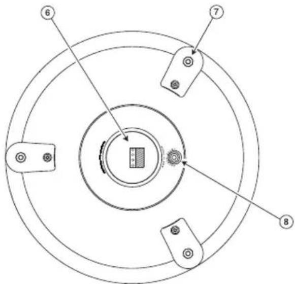
OPS1 Rear Drawing
Package Contents
(1) Orbit Pendant Speaker
(1) Snap-Lock Input Connector
(1) Quick-Snap Clip
(3) Suspension Cables with Forged Eyebolts
(1) Separate Eyebolt
(4) Nuts (may be installed onto eyebolts)
Selecting Power Level
Select the power level using the front-mounted selector switch. The speaker grille must be removed prior to selecting the power level. See Speaker Grille Installation & Removal section for proper grille removal procedures.
Selecting Power Level
The front-mounted selector switch (under grille) is used to set the appropriate power level or impedance for your system. Using a small flat-blade screwdriver, turn the knob until the slot points to the power level you require.
70V/100V Systems
Both power setting scales for 70V and 100V systems are labeled on the speakers. On the 100V scale, the last position clockwise is marked with a Ⓞ (not available) symbol. Do not use this position in 100V systems.

16Ω Systems
The fully counterclockwise position of the setting switch is the 16-ohm position. This setting is suitable for use with low-impedance amplifiers that typically support 4- or 8-ohm speakers. The speaker's higher, 16-ohm impedance makes it easier to combine multiple speakers into series-parallel networks while keeping the total system impedance at a level suitable for low-impedance amplifiers.
Speaker Grille Installation & Removal
Installation
The speaker grille fits tightly! Make sure the tap settings are correct prior to re-installing the grille. Push the speaker grille in until it can go no further. Then, slap around the edge of the grille to seat the grille. The grille is properly seated when it is flush with the edge of the bezel.

natural_image
Top-down view of four hands holding a circular grid pattern (no text or symbols)Removal
Insert a pocketknife blade between the grille and the bezel about 14 " deep and then gently pry the grille upwards. Do this in multiple places around the circumference of the grille to free the grille.

natural_image
Simple line drawing of a curved arrow emerging from a textured base (no text or symbols)Speaker Wiring
Wiring is terminated at a snap-lock input connector. There are two positive and two negative terminals to accommodate daisy-chaining of speakers in a system. All wiring should be done prior to installation and then plugged into the rear of the OPS1.
Daisy-Chaining
The OPS1's snap-lock input connector allows for easy daisy-chaining of speakers by providing a second terminal of each polarity. Refer to the figures for proper wiring for daisy-chaining of terminals.
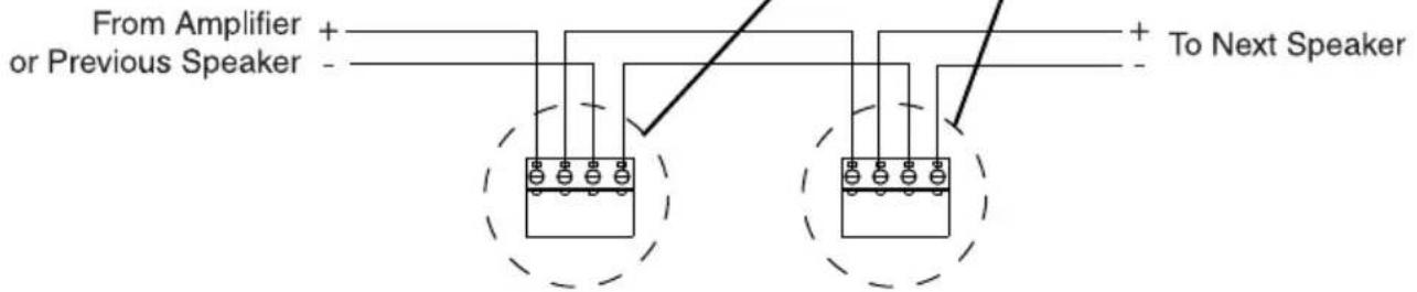
Speaker Phasing
Keep the same polarity terminals wired together to ensure correct phasing. In order to provide the best possible sound, all of the speakers in a system need to be pushing out and pulling in at the same time.
If the connections to one speaker in a system are reversed from the others, that speaker's movement will be out of sync with the other speakers. This will result in a loss of low frequency response and will effect the overall performance of the system.
Speaker Installation
Speaker Assembly
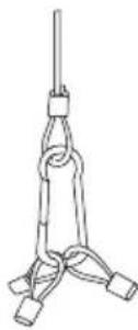
- Screw one nut onto each of the three (3) eye-bolts. These nuts are used as spacers and should be threaded on as far as they can go.
- Screw in eyebolts with captured cable sections into the three (3) threaded anchor points. Make these connections secure but do not over tighten.
- Snap the loops of the three (3) free ends of the cable sections into the quick-snap clip.
- Connect the quick-snap clip to the drop cable loop (not included).
-
A separate eyebolt and nut are provided for installing the safety cable attachment point. Thread the nut on to the eyebolt as far as it will go and thread this assembly into the safety point on the top of the speaker. Make this connection secure but do not over tighten.
-

-

-

-
-


Cables
A BACKUP SAFETY CABLE FOR THE PRIMARY DROP CABLE IS REQUIRED FOR THE PROPER INSTALLATION OF THIS SPEAKER.
SEE THE INSIDE FRONT COVER FOR IMPORTANT WARNING INFORMATION.
Use wire rope or other drop line rated for at least 100 lbs. to ensure a safety margin. If using wire rope with a coating, it is important that the coating be stripped away where any clamping device is being used so that the bare wire cores of the cable are being clamped. The anchor point of the building structure must be able to handle 100 lbs. and all clamping hardware must be very securely tightened unless otherwise instructed. Use only one OPS1 on a set of safety & suspension rigging.
Accessory
CK10 (Cable Kit, 10')
The CK10 is a 10-foot cable with one looped end, a forged eyebolt (with 1/4-20" x 1/2" thread), and an adjustable cable clamp. It is suitable for use as a drop cable or safety cable. The CK10 is available in black, white, or silver.
| SPECIFICATIONS | OPS1 |
| Frequency Response (-10 dB)* | 45 Hz to 19 kHz |
| LF Driver | 6-1/2" MDT Metal-Alloy Cone (MLS Voice Coil Centering System) |
| HF Driver | 20 mm ( ^3/_4 ") Polycarbonate Dome |
| Sensitivity (1W/1m) | 89.5 dBspl |
| Dispersion | 140° |
| Impedance Ratings | Low (16 ohms) / High (70V/100V) |
| Power Input (Max.) | 100W @ 16 ohms; 32W @ 70V/100V |
| Power Settings (in watts) ^ | 70V: 32, 16, 8, 4, 2, 1W100V: 32, 16, 8, 4, 2W |
| Enclosure Material | Fire-rated (94VO) ABS |
| Grille Material | Powder-Coated Perforated Metal |
| Terminations | 4 Terminal Snap-Lock Input Connector |
| Product Weight | 10 lb. |
| Speaker Dimensions | 15" dia. x 9-1/4" D |
| Included Accessories | (1) Quick-Snap Clip; (1) Snap-Lock Input Connector;(3) Suspension Cables w/Forged Eyebolts; (4) Nuts; (1) Separate Eyebolt |
| Optional Accessories | Cable Kit (CK10) |
| Enclosure Finish & Color | Textured Off-white or Dark Gray |
| Listings | Listed to UL Standard 60065 for US & Canada |
* Free Space Response, 16-ohm input
† Front panel, switch-selected.
The Bogen ORBIT Pendant Speaker, Model OPS1, is warranted to be free from defects in material or workmanship for five (5) years from the date of sale to the original purchaser. Any part of the product covered by this warranty that, with normal installation and use, becomes defective will be repaired or replaced by Bogen, at our option, provided the product is shipped insured and prepaid to: Bogen Factory Service Department, 4570 Shelby Air Drive, Suite 11, Memphis, TN 38118 USA. The product will be returned to you freight prepaid. This warranty does not extend to any of our products that have been subjected to abuse, misuse, improper storage, neglect, accident, improper installation or have been modified or repaired or altered in any manner whatsoever, or where the serial number or date code has been removed or defaced.
THE FOREGOING LIMITED WARRANTY IS BOGEN'S SOLE AND EXCLUSIVE WARRANTY AND THE PURCHASER'S SOLE AND EXCLUSIVE REMEDY. BOGEN MAKES NO OTHER WARRANTIES OF ANY KIND, EITHER EXPRESS OR IMPLIED, AND ALL IMPLIED WARRANTIES OF MERCHANTABILITY OR FITNESS FOR A PARTICULAR PURPOSE ARE HEREBY DISCLAIMED AND EXCLUDED TO THE MAXIMUM EXTENT ALLOWABLE BY LAW. Bogen's liability arising out of the manufacture, sale or supplying of products or their use or disposition, whether based upon warranty, contract, tort or otherwise, shall be limited to the price of the product. IN NO EVENT SHALL BOGEN BE LIABLE FOR SPECIAL, INCIDENTAL OR CONSEQUENTIAL DAMAGES (INCLUDING, BUT NOT LIMITED TO, LOSS OF PROFITS, LOSS OF DATA OR LOSS OF USE DAMAGES) ARISING OUT OF THE MANUFACTURE, SALE OR SUPPLYING OF PRODUCTS, EVEN IF BOGEN HAS BEEN ADVISED OF THE POSSIBILITY OF SUCH DAMAGES OR LOSSES. Some States do not allow the exclusion or limitation of incidental or consequential damages, so the above limitation or exclusion may not apply to you. This warranty gives you specific legal rights, and you may also have other rights which vary from State to State.
Products that are out of warranty will also be repaired by the Bogen Factory Service Department -- same address as above or call 201-934-8500. The parts and labor involved in these repairs are warranted for 90 days when repaired by the Bogen Factory Service Department. All shipping charges in addition to parts and labor charges will be at the owner's expense. All returns require a Return Authorization number. For most efficient warranty or repair service, please include a description of the failure.
11/2014
- Orbit Pendant Speaker OPS1B (Dark Gray), OPS1W (Off-White)
- IMPORTANT SAFETY INSTRUCTIONS
- IMPORTANT
- ! WARNING !
- OPS1 Front Drawing
- OPS1 Rear Drawing
- Package Contents
- Selecting Power Level
- 70V/100V Systems
- 16Ω Systems
- Speaker Grille Installation & Removal
- Installation
- Removal
- Speaker Wiring
- Daisy-Chaining
- Speaker Phasing
- Speaker Installation
- Speaker Assembly
- Cables
- Accessory
- CK10 (Cable Kit, 10')
Brand : Bogen
Model : Orbit OPS1
Category : Loudspeaker