
EL5353 - USB extender Icron - Free user manual and instructions
Find the device manual for free EL5353 Icron in PDF.


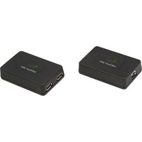
| Product Type | DVI + USB 2.0 KVM Extender System |
| Intended Use | Extend DVI video and USB 2.0/1.1 signals up to 100 m over a single CAT 5e/6/7 cable |
| Local Extender (LEX) Dimensions | 112 mm × 175 mm × 30 mm (4.4" × 6.9" × 1.18") |
| Remote Extender (REX) Dimensions | 112 mm × 175 mm × 30 mm (4.4" × 6.9" × 1.18") |
| Enclosure Material | Silver anodized aluminum |
| Power Supply | Two 5 V DC, 3 A (15 W) AC adapters (included) |
| Input Voltage | 100–240 V AC, 50–60 Hz |
| Maximum Extension Distance | 100 m (330 ft) over CAT 5e/6/7 (CAT 6a/7 STP recommended) |
| Supported Video Resolution | 1920 × 1200 at 24-bit color depth |
| Video Connector (LEX) | 1 × DVI-D In (24-pin) |
| Video Connector (REX) | 1 × DVI-D Out (24-pin) |
| USB Connector (LEX) | 1 × USB Type B |
| USB Connectors (REX) | 3 × USB Type A |
| Link Connector (both) | 1 × RJ45 |
| USB Support | USB 2.0 High‑Speed (up to 40 Mbps), Full‑Speed (up to 12 Mbps), Low‑Speed (up to 1.5 Mbps) |
| USB Hub Support | Up to 4 USB hubs in a single chain |
| Maximum USB Devices | 30 |
| Latency | <1 ms |
| Operating Temperature | 0°C to 40°C (32°F to 104°F) |
| Storage Temperature | -20°C to 70°C (-4°F to 158°F) |
| Operating Humidity | 20% to 80% RH, non‑condensing |
| Certifications | FCC Part 15 Class A, CE Class A, ICES‑003 Class A, RoHS2 |
| Warranty | 2 years |
Frequently Asked Questions - EL5353 Icron
User questions about EL5353 Icron
0 question about this device. Answer the ones you know or ask your own.
Ask a new question about this device
Download the instructions for your USB extender in PDF format for free! Find your manual EL5353 - Icron and take your electronic device back in hand. On this page are published all the documents necessary for the use of your device. EL5353 by Icron.
USER MANUAL EL5353 Icron
EL5353 DVI + USB 2.0 Extender
DVI and USB 2.0 100m CAT 5e/6/7 KVM Extender System
User Guide

Thank you for purchasing the EL5353 KVM Extender.
Please read this guide thoroughly.
This document applies to Part Numbers: 00-00381, 00-00382, 00-00383, 00-00384, 00-00385.
FCC Radio Frequency Interference Statement Warning
This device complies with Part 15 of the FCC rules. Operation is subject to the following two conditions: (1) this device may not cause harmful interference, and (2) this device must accept any interference received including interference that may cause undesired operation.
CE Statement
We, Icron Technologies Corporation, declare under our sole responsibility that the EL5353, to which this declaration relates, is in conformity with European Standard EN 55022, EN 61000, and EN 55024.
IC Statement
This Class A digital apparatus complies with Canadian ICES-003.
WEEE Statement
The European Union has established regulations for the collection and recycling of all waste electrical and electronic equipment (WEEE). Implementation of WEEE regulations may vary slightly by individual EU member states. Please check with your local and state government guidelines for safe disposal and recycling or contact your national WEEE recycling agency for more information.
Product Operation and Storage
Please read and follow all instructions provided with this product, and operate for intended use only. Do not attempt to open the product casing as this may cause damage and will void warranty. Use only the power supplies provided with this product. When not in use, product should be stored in a dry location between -20°C and 70°C.
©2016 Icron Technologies Corporation. All rights reserved. Icron Technologies Corporation, the Icron Technologies Corporation logo, and the Icron Technologies Corporation products referred to herein are either the trademarks or the registered trademarks of Icron Technologies Corporation. All other trademarks are property of their respective owners. Icron Technologies Corporation assumes no responsibility for errors that may appear in this manual. Information contained herein is subject to change without notice.
Document #90-01423-A02
Contents
Introduction 4
Product Contents......4
Requirements....4
About the EL5353 KVM Extender 4
Compatibility and Recommended Setup ....5
The LEX Unit....6
The REX Unit....7
Installation Guide 8
Installing the LEX Unit 8
Installing the REX Unit 8
Connecting the LEX to the REX 9
Connecting a USB device 9
Powering the Extender System 9
Checking the Installation 10
Powering the Extender Systems
Troubleshooting Guide 11
Specifications.... 13
Contacting Technical Support 14
Warranty Information 14
Obtaining Warranty Service 15
Technical Glossary 16
Introduction
This guide provides product information for the EL5353 installation instructions, troubleshooting guidelines, and instructions for contacting Icron regarding technical support and warranty information. The instructions in this guide assume a general knowledge of computer installation procedures, familiarity with cabling requirements and some understanding of USB devices.

provide additional information that could be useful.
CAUTIONS provide important information about an operational requirement.
Product Contents
Packaged with:
• LEX Unit (Local Extender)
- USB 2.0 Cable
• REX Unit (Remote Extender)
• DVI Cable
• (2) 5V DC power adapter
• Quick Start Guide and Warranty Information

The product requires two power adapters, one for the LEX and one for the REX.
Requirements
To complete the installation, you will require the following items that are not included with the product:
- A computer that is USB compatible (with USB compliant operating system) and has a DVI-D/DVI-I output
• USB 1.1 or 2.0 compatible device(s) - A minimum CAT 5e Shielded Twisted Pair (UTP) cable with two CAT 5e/6/7 RJ45 connectors (if using surface cabling),
- A minimum of CAT 5e cabling with two information outlets and two CAT 5e patch cords with CAT 5e RJ45 connectors (if using premise cabling)
OR

While CAT 5e UTP is the minimum category of twisted pair cabling, for the best experience, and to minimize interference and cross-talk, CAT 6a/7 STP is strongly recommended.
When using CAT 5e cabling, the layout and quality of your cable runs and connections becomes extremely important. Please refer to the Cabling section on page 5 for more detailed information.
About the EL5353 KVM Extender
The EL5353 KVM Extender system incorporates ExtremeUSB ^® and HD Video technology, which enables users to extend both DVI and USB 2.0 up to 100 meters (330 feet). The following ExtremeUSB features are included:

• Transparent USB extension
• True Plug and play; no software drivers required
- Works with all major operating systems: Windows ^ , OS X ^ , and Linux ^
Compatibility and Recommended Setup
The product is compatible with many graphics cards, Operating Systems, and monitors supporting up to a 1920 x 1200 resolution. However, there is no guarantee that all devices will be compatible with the product as there are a number of different factors that may impact the operation of this KVM Extender.
This product supports both USB 1.1 and USB 2.0 devices. These devices include: keyboards, mice, flash drives, printers, speakers and microphones. If uncertain whether your USB device(s) can be supported, please contact Technical Support: icron.com/support.
! Test any expected USB or video devices prior to a performing any large deployment. Some devices may not be compatible with the EL5353.
DVI Cables
! Ensure high quality, undamaged DVI cables are used with this product. Low quality or damaged cables may impact product performance and/or result in damage to units.
Cabling
Solid core Category 6a/7 STP cable with Category 6a/7 RJ45 connectors is recommended for best performance. Using unshielded cabling may leave your signal more susceptible to interference and noise which may result in poor video performance or reduced extension distance. Maximum distance and product performance will be reduced in the presence of interference or coiled extension cable.
| Cable Type Electrical Interference Susceptibility | |
| Solid Core CAT 5e/6 UTP High | |
| Solid Core CAT 5e/6 STP Moderate | |
| Solid Core CAT 6a UTP Moderate | |
| Solid Core CAT 6a STP Low (Recommended) | |
| Solid Core CAT 7 STP Low (Recommended) | |

If you are coiling unshielded cabling in your set-up, depending on the quality of the cable and how it is coiled, the maximum distance may be reduced to 50m.
Host Operating Systems
- Windows®
- OS X®
- Linux®
USB Peripherals
• Keyboards & Mice • Printers
• Mass Storage Devices • Speakers
- Microphones
The LEX Unit
The Local Extender (LEX) connects to the computer using the supplied DVI and USB cable.
It's important to use the DVI cable supplied with the product when connecting the LEX to the host computer to ensure proper operation.
Front View

Rear View

| ITEM | TYPE DESCRIPTION | |
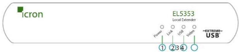
| 1 Power LED (Green) | Green Light: The system is powered and ready to use.No Light: The system does not have power. | |
| 2 Link LED (Green) | Green Light: The LEX and REX are able to communicate with each other across the link.No Light: There is no communication between the LEX and REX. | |
| 3 USB LED (Green) | Green Light: The LEX and the host computer are communicating with each other and working.Blinking Green Light: The host computer has entered power saving mode.No Light: The host and the LEX are not communicating or not connected. | |
| 4 Video LED (Green) | Solid Green Light: HDCP (digital rights management) content is being transmitted.Blinking Green Light: Video (non-HDCP) content is being transmitted.No Light: There is no video being transmitted. | |
| 5 Config Reserved for use by Icron Technologies. | ||
| 6 Link Port (RJ45) Accepts RJ45 connector for CAT 5e/6/7 cabling. | ||
| 7 DVI-D In Accepts DVI-D connector for video input from the host computer. | ||
| 8 Device Port (USB Type B) Used to connect the LEX unit to the host computer. | ||
| 9 Power Port Connects to the AC power supply. | ||
The REX Unit
The Remote Extender (REX) provides DVI output to a monitor and three USB Type A ports for standard USB devices. Additional devices may be connected by attaching USB hubs.
Front View
Rear View

| ITEM TYPE DESCRIPTION | ||
| 1 Power LED (Green) Green Light: | The system is powered and ready to use.No Light: The system does not have power. | |
| 2 Link LED (Green) Green Light: | The LEX and REX are able to communicate with each other across the link.No Light: There is no communication between the LEX and REX. | |
| 3 USB LED (Green) Green Light: | The LEX and the host computer are communicating with each other and working.Blinking Green Light: The host computer has entered power saving mode.No Light: The host and the LEX are not communicating or not connected. | |
| 4 Video LED (Green) Solid Green Light: | HDCP (digital rights management) content is being transmitted.Blinking Green Light: Video (non-HDCP) content is being transmitted.No Light: There is no video being transmitted. | |
| 5 Config Reserved for use by Icron | Technologies. | |
| 6 Link Port (RJ45) Accepts RJ45 connector for CAT 5e/6/7 cabling. | ||
| 7 DVI-D Out Accepts DVI-D connector to the remote monitor. | ||
| 8 Device Port (USB Type A) Accepts USB device(s). | ||
| 9 Power Port Connects to the AC power supply. | ||
Installation Guide
Before you can install the product, you need to prepare your site:

flowchart
graph LR
    A["Computer"] -->|DVI & USB up to 100m CAT 5e/6/7 (STP recommended)| B["REXLEX"]
    B --> C["Monitor"]
    C -->|USB| A
- Determine where the computer is to be located and set up the computer.
- Determine where you want to locate the remote desktop including the monitor, keyboard, mouse and any other USB device(s).
- If you are using surface cabling, the product supports a maximum distance of 100m (330 ft).
OR
If you are using premise cabling, ensure the CAT 5e/6/7 cabling is installed between the two locations, with CAT 5e/6/7 information outlets located near both the computer and the USB device(s), and the total length, including patch cords is no more than 100m.
Installing the LEX Unit
- Place the LEX unit near the computer.
- Install the supplied USB cable to the USB port on the LEX, and an available USB 2.0/1.1 Type A Port on the computer.
- Install the supplied DVI cable to the LEX (DVI-D In), and an available DVI Port on the computer.
- Plug the 5V, 3A power adapter into a suitable AC outlet near the LEX.
Installing the REX Unit
- Place the REX unit near the monitor and USB device(s) in the desired remote location.
- Connect the REX DVI-D Out to the monitor with a high quality DVI cable.
- Plug in your USB device(s) into the USB ports on the REX.
- Plug the 5V, 3A power adapter into a suitable AC outlet near the REX.
Connecting the LEX to the REX

While unshielded cabling may be used, to ensure proper operation, it is recommended that solid core CAT 6a/7 STP cabling be used to connect the local extender to the remote extender. The cabling must have a straight-through conductor configuration with no crossovers and must be terminated with CAT 6a/7 connectors to qualify as CAT 6a/7.
With Surface Cabling
-
Plug one end of the CAT 5e/6/7 cabling (not included) into the Link port (RJ45) on the LEX.
-
Plug the other end of the CAT 5e/6/7 cabling into the Link port (RJ45) on the REX.
With Premise Cabling
-
Plug one end of a CAT 5e/6/7 patch cord (not included) into the Link port (RJ45) on the LEX.
-
Plug the other end of the patch cord into the CAT 5e/6/7 information outlet near the host computer.
-
Plug one end of the second CAT 5e/6/7 patch cord (not included) into the Link port (RJ45) on the REX.
-
Plug the other end of the second patch cord into the CAT 5e/6/7 information outlet near the USB device(s).
Connecting a USB Device
-
Install any software required to operate the USB device(s). Refer to the documentation for the USB device(s), as required.
-
Connect the USB device to the device port on the REX.
-
Check that the device is detected and installed properly in the operating system.
Powering the Extender System
-
Power the Local Extender with the included 5V AC adapter.
-
Power the Remote Extender with the included 5V AC adapter.
! Use only the power adapters supplied with the product. Use of substitute adapters may cause permanent damage to the system and will void the warranty.
Checking the Installation
- On the LEX and REX units, check that the Power, Link, USB, and Video LEDs are on. If the Link LED is off, then the cabling between the LEX and REX is not installed properly or is defective.
- Check to see if the USB LED is on and the Video LED is blinking or on; if they are not this indicates there is no USB data or video data. Check the DVI and USB connections to the host computer, and the DVI connection to the monitor. Check to see if any USB devices are connected to the REX.
- For Windows users, open Device Manager to confirm that the USB functionality of the EL5353 has been installed correctly. Expand the entry for Universal Serial Bus controllers by clicking the "+" sign. If the EL5353 has been installed correctly, you should find it listed as one "Generic Hub".

To open Device Manager in Windows 10/8/8.1 or Windows 7:
Open the Start menu, right click on "Computer" then select: Manage >> Device Manager

- For OS X users, open the System Profiler to confirm that the EL5353 has installed correctly. In the left hand column under Hardware, select "USB" and inspect the right hand panel. If the EL5353 has been installed correctly, you should find it listed as a "Hub" under the USB High-Speed Bus/USB Bus.

To open System Profiler in OS X:
Open the Finder, select Applications, then open the Utilities folder and double click on the System Profiler icon.
- If the product is not displaying video or the EL5353 fails to be detected by your operating system, please consult the Troubleshooting section of this guide.
Troubleshooting Guide
The following table provides troubleshooting tips. The topics are arranged in the order in which they should be executed, in most situations. If you are unable to resolve the problem after following these instructions, please contact Technical Support for further assistance.
| PROBLEM CAUSE SOLUTION | ||
| All LEDs on LEX are off. | The LEX is not receiving power from the power adapter. | Ensure that the power adapter is properly connected to the LEX.Check that the power adapter is connected to a live source of electrical power. |
| All LEDs on REX are off. | The REX is not receiving power from the power adapter. | Ensure that the power adapter is properly connected to the REX.Check that the power adapter is connected to a live source of electrical power. |
| Link LEDs on LEX and REX are off. | There is no connection between the LEX and REX. | Ensure a CAT 5e/6/7 cable is connected between the LEX and REX. Ensure CAT 5e UTP or better cabling with conductor RJ45 connectors is used.Connect a short CAT 5e/6/7 patch cord between the LEX and REX to determine if the original CAT cable is defective.Ensure the CAT 5e/6/7 cable is as straight as possible (i.e. not coiled). |
| Link LED on LEX is on, USB LED on LEX is off. | The host computer is not powered on.The LEX is not connected to the computer.The computer does not support USB hubs.The unit is malfunctioning.The USB cable is defective. | Disconnect all USB devices from the REX.Disconnect the LEX from the computer.Disconnect the LEX and REX from the power adapters.Reconnect the USB device(s) to the REX.Reconnect the LEX to the computer.Reconnect the LEX to the power adapter.Reconnect the REX to the power adapter.If the USB LED continues to stay off, contact Technical Support. |
| All LEDs on both the LEX and REX are on, but the USB device does not operate correctly or is detected as an “Unknown Device” in the operating system. | The USB device is malfunctioning.The computer does not recognize the USB device.The application software for the device is not operating.The KVM extender product is malfunctioning. | 1. Disconnect the KVM extender product from the computer.2. Connect the USB device directly to the USB port on the computer.3. If the device does not operate properly, consult the user documentation for the USB device.4. Update your system BIOS, chipset or USB Host controller drivers from your System/Motherboard manufacturer’s website.5. Make sure the operating system has all the latest updates installed.6. If the USB device operates properly when directly connected to the computer, connect another device (of a different type) to the KVM extender product. Connect the KVM extender product to the computer.7. If the second USB device does not operate, the KVM extender product may be malfunctioning. Contact Technical Support for assistance.8. If the second device does operate properly, the first device may not be compatible with the KVM extender product. |
| Blinking Video on the Sink (Monitor). | A poor quality or damaged CAT 5e cable is being used.The cabling is coiled. | 1. Remove all loops in the CAT 5e/6/7 cable.2. Confirm extender operation with a CAT 5e/6/7 patch cable. |
| Video frames are being dropped. | The extender is not compatible with the HDCP source and/or sink device. | 1. Contact Technical Support. |
| Video LED is off. | One or both of the DVI cables are not connected, are of poor quality or are malfunctioning.The sink or source is not supported.The KVM extender product is malfunctioning. | 1. Confirm extender operation with DVI cables that are less than 78” (2m) in length and have connection between each connectors shield.2. Confirm extender operation with a CAT 5e/6/7 patch cable.3. Contact Technical Support. |
Specifications
| Range | Up to 100m (330 ft) over a single CAT 5e/6/7 cable. Solid core CAT 6a/7 STP recommended for best performance. |
| Video Resolution & Depth 1920 x 1200 | 24-bit color depth |
| Latency Less than 1ms | |
| USB Device Support & Throughputs | High-Speed devices (USB 2.0) - up to 40 Mbps Full-Speed devices (USB 2.0 & 1.1) - up to 12 Mbps Low-Speed devices (USB 2.0 & 1.1) - up to 1.5 Mbps |
| USB Hub Support Any single chain can | include up to 4 USB hubs |
| USB Host Support xHCI (USB 3.0), EHCI | (USB 2.0), OHCI/UHCI (USB 1.1) |
| AC Adapters Input: 100-240 V AC, 50 – | 60 Hz | Output: 5V DC, 3A (15 W) |
| Power Available to USB Device at REX | 500 mA each port |
| Maximum USB Devices Supported 30 | USB devices |
| Enclosure Material Silver anodized alum | minum |
| Enclosure Dimensions 112 mm x 175 mm x 30 mm (4.4" x 6.9" x 1.18") | |
| LOCAL EXTENDER (LEX) | |
| Video Connector 1 x DVI-D In (24-pin connector) | |
| USB Connector 1 x USB Type B Receptacle | |
| Link Connector 1 x RJ45 | |
| REMOTE EXTENDER (REX) | |
| Video Connector 1 x DVI-D Out (24-pin connector) | |
| Link Connector 1 x RJ45 | |
| USB Connector 3 x USB Type A Receptacles | |
| ENVIRONMENTAL | |
| Operating Temperature Range | 0°C to 40°C (32°F to 104°F) |
| Storage Temperature Range | -20°C to 70°C (-4°F to 158°F) |
| Operating Humidity | 20% to 80% relative humidity, non-condensing |
| COMPLIANCE | |
| Emissions | FCC Part 15 Class A, CE Class A, ICES-003 Class A |
| Immunity | CE EN 55024 |
| Environmental | RoHS2 (CE) |
| SUPPORT | |
| Warranty | 2-year |
Contacting Technical Support
If you are experiencing problems not referenced in Troubleshooting section, contact Icron's Technical Support for further assistance.
Warranty Information
Limited Hardware Warranty
Icron Technologies Corporation warrants that any hardware products accompanying this documentation shall be free from significant defects in material and workmanship for a period of two years from the date of purchase. Icron Technologies Corporation's hardware warranty extends to Licensee, its customers, and end users.
The Warranty does not include repair of failures caused by: misuse, neglect, accident, modification, operation outside a normal operating environment, failure caused by service of the device by non-authorized servicers, or failure caused by a product for which Icron Technologies Corporation is not responsible. Opening the enclosures will void warranty.
Hardware Remedies
Icron Technologies Corporation's entire liability and the Licensee's exclusive remedy for any breach of warranty, shall be, at Icron Technologies Corporation's option, either (a) return of the price paid or (b) repair or replacement of hardware, which will be warranted for the remainder of the original warranty period or 30 days, whichever is longer. These remedies are void if failure of the hardware has resulted from accident, abuse, or misapplication.
Limitation of Liability
The hardware warranty set forth in this agreement replaces all other warranties. Icron Technologies Corporation expressly disclaims all other merchantability and fitness for a particular purpose and noninfringement of third-party rights with respect to the hardware.
Icron Technologies Corporation dealer, agent, or employee is not authorized to make any modification extension, or addition to this warranty. Under no circumstances will Icron Technologies Corporation, its suppliers or licensors be liable for any costs of procurement or substitute products or services, lost profits, loss of information or data, or any other special, indirect, consequential, or incidental damages arising in any way out of the sale of, use of, or inability to use Icron Technologies Corporation product or service, even if Icron Technologies Corporation, its suppliers or licensors have been advised of the possibility of such damages. In no case shall Icron Technologies Corporation, its suppliers and licensors' liability exceed the actual money paid for the products at issue.
Since some jurisdictions do not allow the limitation of implied warranties of liability for incidental, consequential, special or indirect damages, the above limitation may not always apply. The above limitation will not apply in case of personal injury where and to the extent that applicable law requires such liability..
Obtaining Warranty Service
To obtain warranty service, you must contact Icron Technologies Corporation within the warranty period for a Return Material Authorization (RMA) number. Icron Technologies Corporation will not accept returns without an authorized RMA number. Be sure you have the serial numbers of the local extender and remote extender before calling. Package the product appropriately for safe shipment and mark the RMA number on the outside of the package. The package must be sent prepaid to Icron Technologies Corporation. We recommend that you insure it or send it by a method that provides for tracking of the package. The repaired or replaced item will be shipped to you, at Icron Technologies Corporation's expense, not later than thirty days after Icron Technologies Corporation receives the defective product.
Address the returned product to:
RMA Coordinator
Icron Technologies Corporation
4664 Lougheed Highway, Suite 221
Burnaby, BC Canada
V5C 5T5
Contacting Sales
sales@icron.com
Tel: +1 604 638 3920
Contacting Technical Support
icron.com/support
Tel: +1 604 638 3939
To help us serve you better, please include the following information with your technical support request:
• Host computer make and model
• Type of Operating System installed (e.g. Windows 8.1, Windows 10, OS X 10.11, etc.)
• Part number and serial number for both the LEX and REX units
• Make and model of any USB device(s) attached to the EL5353
- Description of the installation (Host computer model, transmission media used, and information on the USB devices)
• Description of the problem
Technical Glossary
Category 5e/6/7 (CAT 5e/6/7) Network Cabling
Category 5e cable is commonly also referred to as CAT 5e. This cabling is available in either solid or stranded twisted pair copper wire variants and as UTP (Unshielded Twisted Pair) or STP (Shielded Twisted Pair). UTP cables are not surrounded by any shielding making them more susceptible to electromagnetic interference (EMI). STP cables include shielding over each individual pair of copper wires and provides better protection against EMI. For best performance of this product, solid core Category 6a/7 STP cable with Category 6a/7 RJ45 connectors is recommended.
USB Cables
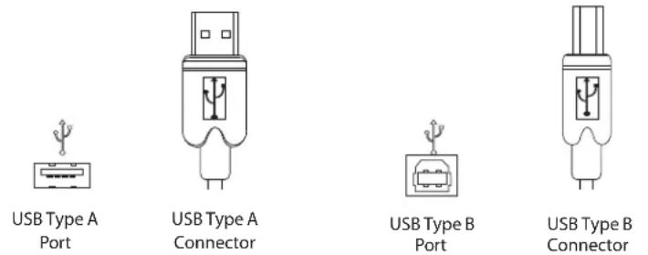
USB cables have two distinct connectors. The Type A connector is used to connect the cable from a USB device to the Type A port on a computer or hub. The Type B connector is used to attach the USB cable to a USB device.
RJ45
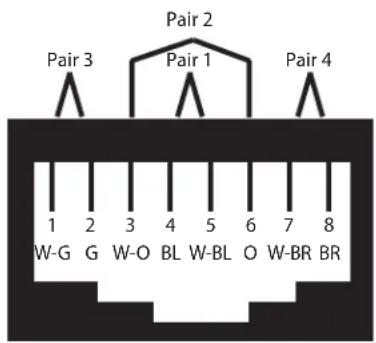
The Registered Jack (RJ) physical interface is what connects the network cabling (CAT 5e/6/7) to the Local Extender unit and Remote Extender unit. You may use either the T568A scheme (Table 1) or the T568B scheme (Table 2) for cable termination as this extender uses all four pairs of the cable. RJ45 connectors are sometimes also referred to as 8P8C connectors.
RJ45 Pin Positioning
Table 1 - T568A Wiring Table 2 - T568B Wiring
| PIN PAIR WIRE CABLE COLOR PIN PAIR WIRE CABLE COLOR | |||
| 1 3 1 WHITE/GREEN 1 2 1 WHITE/ORANGE | |||
| 2 3 2 GREEN 2 2 2 ORANGE | |||
| 3 2 1 WHITE/ORANGE 3 3 1 WHITE/GREEN | |||
| 4 1 2 BLUE 4 1 2 BLUE | |||
| 5 1 1 WHITE/BLUE | 5 1 1 WHITE/BLUE | ||
| 6 2 2 ORANGE | 6 3 2 GREEN | ||
| 7 4 1 WHITE/BROWN | 7 4 1 WHITE/BROWN | ||
| 8 4 2 BROWN | 8 4 2 BROWN | ||


icron
Icron Technologies Corporation
4664 Lougheed Highway, Suite 221
Burnaby, BC Canada
V5C 5T5
Tel: +1 604 638 3920
Fax: +1 604 638 3930
icron.com

- EL5353 DVI + USB 2.0 Extender
- DVI and USB 2.0 100m CAT 5e/6/7 KVM Extender System
- User Guide
- Thank you for purchasing the EL5353 KVM Extender.
- Please read this guide thoroughly.
- FCC Radio Frequency Interference Statement Warning
- CE Statement
- IC Statement
- WEEE Statement
- Product Operation and Storage
- Contents
- Introduction 4
- Installation Guide 8
- Powering the Extender Systems
- Introduction
- Product Contents
- Requirements
- OR
- About the EL5353 KVM Extender
- Compatibility and Recommended Setup
- DVI Cables
- Cabling
- Host Operating Systems
- USB Peripherals
- The LEX Unit
- The REX Unit
- Installation Guide
- Installing the LEX Unit
- Installing the REX Unit
- Connecting the LEX to the REX
- With Surface Cabling
- With Premise Cabling
- Connecting a USB Device
- Powering the Extender System
- Checking the Installation
- Troubleshooting Guide
- Contacting Technical Support
- Warranty Information
- Limited Hardware Warranty
- Hardware Remedies
- Limitation of Liability
- Obtaining Warranty Service
- Contacting Sales
- Technical Glossary
- Category 5e/6/7 (CAT 5e/6/7) Network Cabling
- USB Cables
- RJ45
- RJ45 Pin Positioning
- icron
- Icron Technologies Corporation
Brand : Icron
Model : EL5353
Category : USB extender