
AM-71B-V02 - Uncategorized Vivotek - Free user manual and instructions
Find the device manual for free AM-71B-V02 Vivotek in PDF.


| Product Type | Conduit Box (Mounting Accessory) |
| Brand | Vivotek |
| Model | AM-71B-V02 |
| Compatible Cameras | FD9368-HTV, FD9389 series, IT9360-HT, FD9360-H, FD9380-H, IT9389-H-V2, FD9388-HTV, IT9366-HT, IT9359-H-V2 |
| Functions | Weatherproof enclosure for cable connections, supports 3/4" conduit, provides alignment sticker for easy installation |
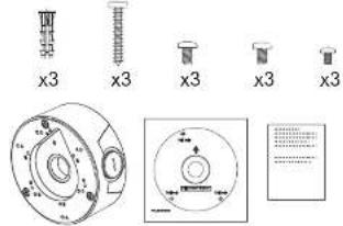
| Package Contents | Conduit box, top cover, rubber seal, cable gland, alignment sticker, screws (M4x10, M4x8, M3x7) |
| Material | Metal (estimated) |
| Weight | Approximately 0.5 kg (estimated) |
| Dimensions (Box) | Diameter approx. 120 mm, depth approx. 60 mm (estimated) |
| Mounting Type | Wall mount with junction box |
| Waterproof Rating | Yes, with rubber seal and cable gland |
| Installation | Attach alignment sticker, drill holes, install box, route cables, secure top cover |
| Maintenance | Periodically check seal integrity and screw tightness |
| Safety | Use appropriate conduit fittings, ensure proper grounding |
| Spare Parts | Rubber seal, cable gland, screws (available from Vivotek) |
| Repairability | Replaceable components |
| General Information | Part no.: 5019042700; Accessory Ordering part no.: VIO100220401; Revision 1.0 |
Frequently Asked Questions - AM-71B-V02 Vivotek
User questions about AM-71B-V02 Vivotek
0 question about this device. Answer the ones you know or ask your own.
Ask a new question about this device
Download the instructions for your Uncategorized in PDF format for free! Find your manual AM-71B-V02 - Vivotek and take your electronic device back in hand. On this page are published all the documents necessary for the use of your device. AM-71B-V02 by Vivotek.
USER MANUAL AM-71B-V02 Vivotek
VIVOTEK Mounting Accessories
AM-71B\_V02 Conduit Box
Installation Guide
Revision History:
Rev. 1.0: Initial release
Part no.: 5019042700
Accessory Ordering part no.: VIO100220401

Compatible VIVOTEK Cameras
| Hole Type Applicable Cameras Screw No. of Screws | |||
| A FD9368-HTV, FD9368-HTV M4x10 3 | |||
| A FD9389 series M4x8 3 | |||
| B IT9360-HT M4x8 3 | |||
| C FD9360-H, FD9380-H M4x8 3 | |||
| D IT9389-H-V2 M3x7 3 | |||
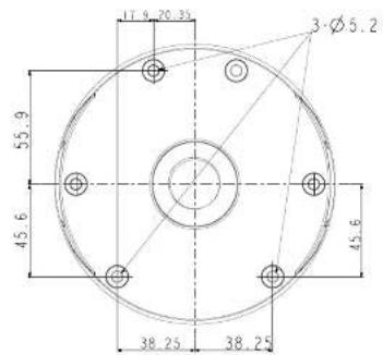
Mounting Dimensions
Package Contents

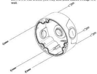
Attach the included alignment sticker to a preferred position. Drill holes on the wall and install the junction box. If space behind the wall allows, you may also pass cables through the wall.

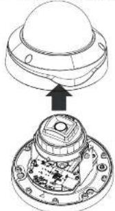
Loosen and remove the camera top cover. (Using one of the supported cameras as an example)
natural_image
Technical diagram of a mechanical assembly with a top component and internal components (no text or symbols)
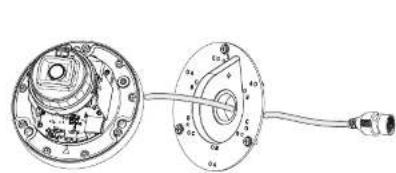
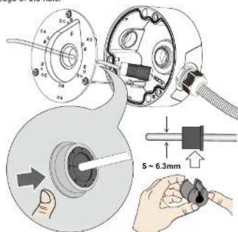
Pass the camera's Ethernet cable through the center hole of the box and the rubber seal.

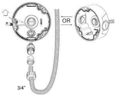
Install the waterproof components of the cable gland to your Ethernet cable following the QIG of your camera. The cable gland will be placed within the protection of the box.
natural_image
Technical diagram of a mechanical assembly with two views (top and side), no visible text or symbols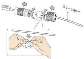

installation
Remove the top cover
1
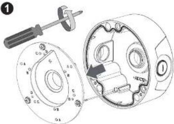
A 3/4" conduit is required for routing the cables with waterproof connection.
2
natural_image
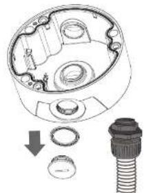
Technical diagram of a mechanical assembly with no visible text or symbolsInstall the cable gland and pass cables through it.
!
If using the bottom hole, seal the center hole.
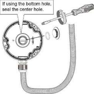

Make sure the rubber seal is properly installed to the center hole. The outer rim of the seal must be through and cover the edge of the hole.

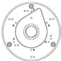
A: FD9389 series, FD9368-HTV, FD9388-HTV B: IT9366-HT
C: FD9360-H, FD9380-H D: IT9359-H-V2

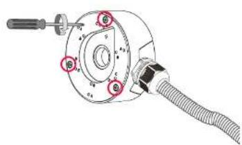
Secure the top cover by fastening 3 cross-head screws.

Install the camera using the corresponding mounting holes.
natural_image
Mechanical assembly diagram showing a cylindrical component with attached cable and adjustment knobs (no text or labels)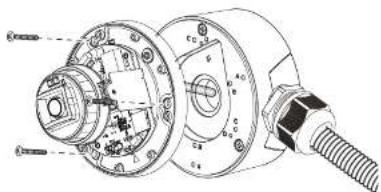
11 Open a live view console and adjust the shooting direction. Refer to the camera's QIG for more information.
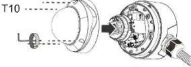
Secure the camera top cover.
Brand : Vivotek
Model : AM-71B-V02
Category : Uncategorized