
Cody M502402ENTR - Lock Baldwin - Free user manual and instructions
Find the device manual for free Cody M502402ENTR Baldwin in PDF.


| Product Type | Entry Door Lockset |
| Brand | Baldwin |
| Model | Cody M502402ENTR |
| Finish | Venetian Bronze |
| Backset | 2-3/8 in or 2-3/4 in adjustable |
| Door Thickness | 1-3/8 in to 1-3/4 in |
| Handing | Reversible for left or right hand doors |
| Lock Type | Keyed entry with push-button convenience |
| Security Grade | Grade 2 (residential high security) |
| Material | Zinc die-cast chassis, steel deadbolt |
| Weight | Approx. 2.6 lbs (1.2 kg) |
| Installation | DIY compatible with standard tools |
| Key Type | Traditional metal key |
| Operation | Turn key or push interior button to lock/unlock |
| Maintenance | Lubricate lock mechanism annually with graphite; clean with damp cloth |
| Spare Parts Availability | Replacement keys and finish parts available from Baldwin |
| Warranty | Limited lifetime warranty |
| Certification | ANSI/BHMA Grade 2 certified |
Frequently Asked Questions - Cody M502402ENTR Baldwin
User questions about Cody M502402ENTR Baldwin
0 question about this device. Answer the ones you know or ask your own.
Ask a new question about this device
Download the instructions for your Lock in PDF format for free! Find your manual Cody M502402ENTR - Baldwin and take your electronic device back in hand. On this page are published all the documents necessary for the use of your device. Cody M502402ENTR by Baldwin.
USER MANUAL Cody M502402ENTR Baldwin
Baldwin Hardware Corporation

Baldwin 2-1/2 and 2-3/4 backset Mortise locks are designed for residential use in UL-listed fire-rated openings rated for 3-hour maximum. Meets U.S. UL10C (positive pressure) and CANS-104M80. In the event of fire, lock will be permanently disabled when mechanism reaches temperatures above 400° F. Use in accordance with local fire code regulations.
Mortise Lock Installation Instructions
TOOLS REQUIRED
1 Pencil
2 No. 2 and No. 3 Phillips Head
Screwdrivers
3 No. 1 and No. 2 Slotted Screwdrivers
4 1/8" Allen Head Wrench
5 3/4" Wood Chisel or Corner Chisel
6 Measuring Device
7 Lock Mortising Tool (Recommended)
8 Router and Lock Face Template
9 Combination Square
10 Awl
11 Hacksaw
12 File (Wood Rasp and Metal)
13 Baldwin Aligning Tool
14 Drill and assorted Drill Bits (1/16", 1/8", 5/16", 3/8", 3/4", 1", 1-1/4")
15 Screw Wax or Soap
16 Powder Chalk, Graphite or Lipstick
Note: In order to successfully install a mortise lock and trim, a minimum of average skill level is required with use of the above listed tools.
Read and understand the provided instructions BEFORE attempting to mark or cut the door and/or frame. If there are any questions before you begin the installation, phone or visit your nearest Baldwin Distributor or contact the Technical Service Department at Baldwin at 610.777.7811.
Diagram A
ENTRANCE HANDLESET
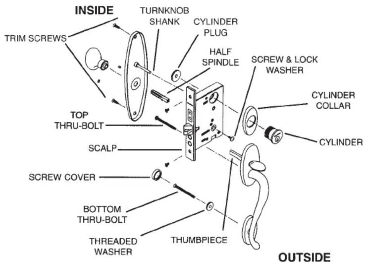
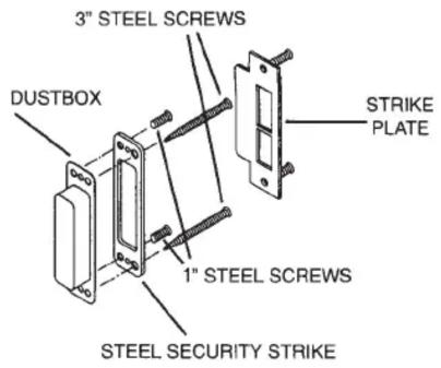
Diagram B
ENTRANCE LEVER/KNOB SET

DOOR CONDITIONS

HAND OF DOOR IS ALWAYS DETERMINED FROM THE OUTSIDE
Here are some rules to follow:
- The outside of an exterior door is the street or entrance side.
-
The outside of a room is the hall side.
-
The outside of a single communicating door is the side from which the hinges are not visible when the door is closed.
- The outside of a closet door is the room or hall side.
GENERAL NOTES
Paper template is designed for 1-3/4" thick doors. For extra thick doors, measure backset from center of door edge. Tape supplied template to the door to locate fastener pattern for lock and trim.
When installing hardware on metal or fiberglass doors, ensure the door was designed to accommodate mortise locks. If in doubt, check with your local door distributor or door manufacturer.
Removal of hardware from doors is recommended before painting and finishing of the door. Allow paint/stain to fully cure before reinstalling hardware, usually ten days to two weeks. Check paint manufacturer instructions.
Retain these instructions in a safe place should you need to disassemble the lock trim or require Baldwin's assistance.
Mortise Lock Handleset Installation Instructions
Mark the Door Double Check Compatibility
1

Mark the door at 37-1/2" - 40" above finished floor, or if retrofit, at appropriate location to coordinate with existing strike preparations. This will be center line of the lock and will put the knob/lever at 36" - 39" above the floor.
2
of Door Stile & Trim
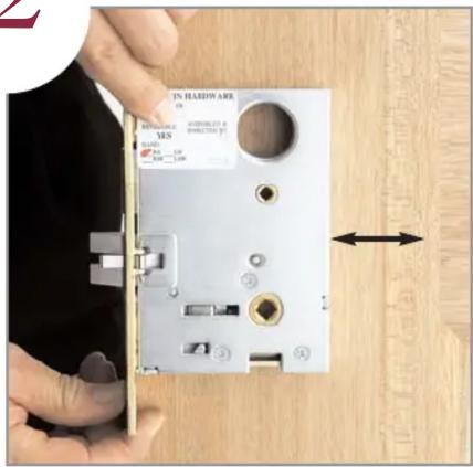
Make sure that the door stile will accommodate the intended lock.
3
Determine Hole Pattern
Required for Trim on
Blue Sheet
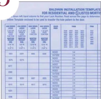
Determine hole pattern required for trim using Installation Template Guide Chart (blue sheet shown). Mark the listed holes on the yellow lock template (figure 7) enclosed with the lock. Ensure trim will not interfere with door stop or extend over door panel or glass.
4
Mortise Lock Pocket
For Lock Body
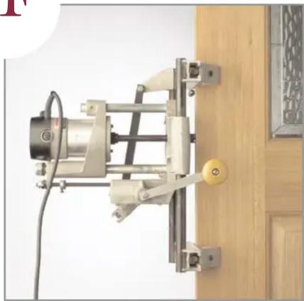
Mortise the pocket in the door 1/8" deeper than the lock being installed. Refer to the Installation Template Guide Chart (blue sheet) for exact size of mortise pocket.
5
A Prepare for Lock Front

Rout for the lock front.
5B
Prepare for Lock Front
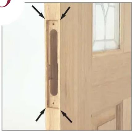
Square the Corners.
6
Cut Relief Pockets
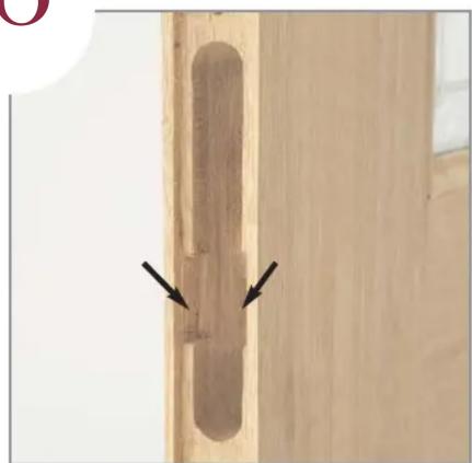
Cut the relief pockets 3/8" deep on both sides for the Latch Hinge, 2-1/2" and 2-3/4" backset only. (Does not apply for 1" front.)
Mark Door
7
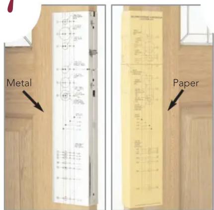
For 1-3/4" doors, fold the yellow lock template and attach to door using Installation Template Guide. Mark door at appropriate locations for lock and trim. MARK APPROPRIATE BACKSET. (Extra thick door conditions, see General Notes.) Metal template 8498.000 is available for purchase.
Drill Holes
8
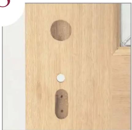
Drill appropriate holes as indicated on yellow lock template. DO NOT OVERSIZE HOLES. Only top two holes are drilled for knob to knob and lever to lever sets.
9
Install Cylinder Plug

Thread the cylinder plug into interior side of lock. Place a strip of tape over plug to keep it from turning. Notch must be located as shown. (Double cylinder functions: OMIT THIS STEP.)
Install Lock
10
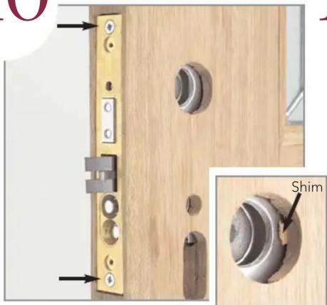
Drill two pilot holes for the lock face, adjust the bevel and install the lock. Shim between the lock and door on cylinder side as shown to prohibit the cylinder from pulling the lock case off center. (Failure to shim the lock may cause the cylinder to sit unevenly on the surface of the trim.)
Insert Spindle
11

For handleset trim install the spindle from the inside with V groove facing bottom door hinge and thread the screw and lock washer into the spindle from the outside. Tighten securely. For knob to knob and lever to lever sets, install spindle from outside - go to step 13.
12
Size Thumbpiece
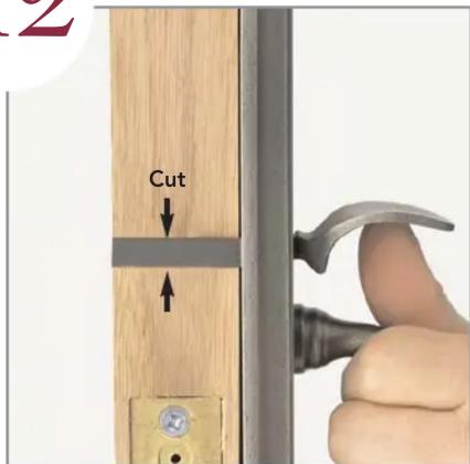
Cut the thumbpiece so that it will fully engage the lift lever on the bottom of the lock.
Install Cylinder
13

Place the cylinder through the trim. Partially insert key into cylinder. Thread the cylinder into the lock until it is against the trim and Baldwin name is horizontal. For knob to knob and lever to lever sets - Install aligning bushing and fasten trim with supplied screws. Remove bushing - go to step 16.
Install Thru-Bolts
14
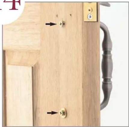
Start the thru-bolts which will hold the exterior trim. (Use screw cover washer under the bottom thru-bolt.) Tighten both securely.
15
Size & Cut Thumbturn

Cut the thumbturn tailpiece so that it goes halfway through the lock (as in step 12).
Install Interior Trim
16
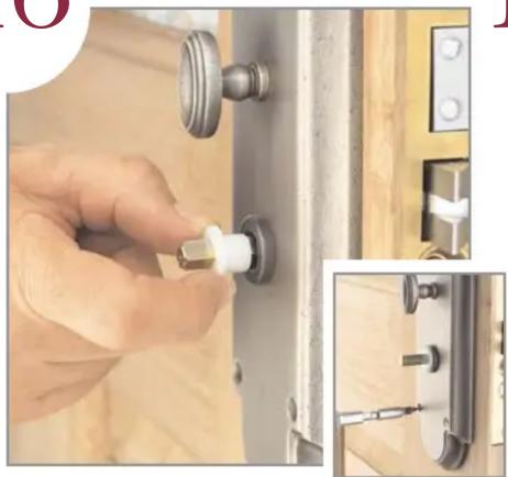
Place the interior trim on the door. Slide the aligning bushing onto the spindle so it fits into the knob hole. Drill pilot holes and fasten interior trim with supplied fasteners. Remove bushing and discard.
Complete Trim Installation
17
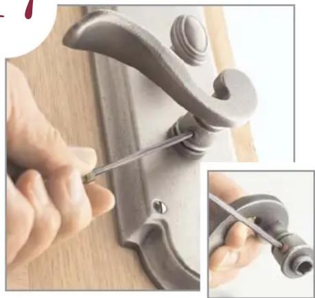
Start the set screw before sliding the knob or lever onto the spindle. Slide knob or lever onto the spindle and tighten securely. For knob to knob and lever to lever sets - install both sides - go to step 19.
18 19 Install
Install Screw Cover

Thread decorative screw cover onto threaded washer.
Tighten Cylinder
Set Screw

Tighten the cylinder set screw by turning clockwise. Do not over tighten. Do not use a power screw driver.
Install Armor Front
20

Install the armor front with the small phillips head screws supplied.
21
*Mark and Mortise Jamb for Strike Location

Mark the Jamb for the proper strike location. Coat extended latch bolt with graphite, powdered chalk or lipstick. Retract the bolt, close the door and actuate the knob or lever several times to mark the jamb. Add approximately 1/32" clearance from that mark.
Install Dust Box & Security Strike
22
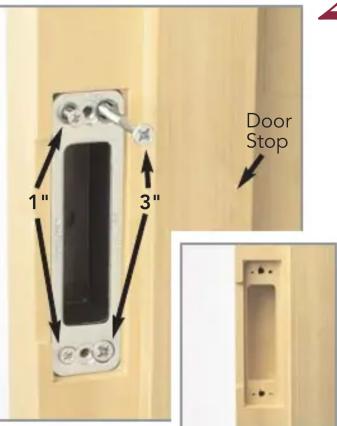
Drill pilot holes for security strike and relief holes for finished strike. Install dust box and security strike with 1" and 3" screws on the stop side of the plate. Note: Security Strikes are supplied only with locks which utilize cylinders.
Install Strike Plate
23
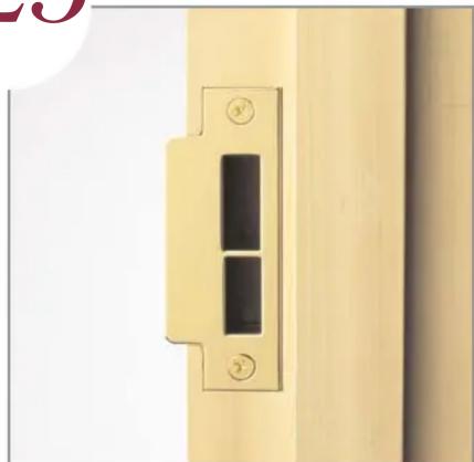
Install strike plate with supplied machine screws.


Brand : Baldwin
Model : Cody M502402ENTR
Category : Lock