
MC500.4 - Receiver ALTO - Free user manual and instructions
Find the device manual for free MC500.4 ALTO in PDF.


| Type of product | Car stereo receiver |
| Brand | Alto |
| Model | MC500.4 |
| Dimensions (W x H x D) | 7.1 x 2.0 x 6.3 inches (180 x 50 x 160 mm) |
| Weight | 3.3 lbs (1.5 kg) |
| Power supply | 12 V DC (negative ground) |
| Maximum power output | 4 x 50 W RMS |
| Peak power output | 4 x 100 W |
| Speaker impedance | 4 - 8 ohms |
| Frequency response | 20 Hz - 20 kHz |
| Signal-to-noise ratio | ≥ 90 dB |
| FM tuner frequency range | 87.5 - 108 MHz |
| AM tuner frequency range | 530 - 1710 kHz |
| Playback media | CD, CD-R, CD-RW, USB, AUX |
| Bluetooth | Yes (version 4.2, A2DP, AVRCP) |
| USB port | Front USB (5V, 1A charging) |
| Auxiliary input | 3.5 mm stereo jack |
| Remote control | Included (wired or IR) |
| Maintenance and cleaning | Wipe with a soft, dry cloth. Do not use solvents. |
| Safety | Replace fuse with specified rating only. Disconnect battery before installation. |
| Spare parts and repairability | Contact Alto service center for genuine parts. Repair by qualified technician only. |
Frequently Asked Questions - MC500.4 ALTO
User questions about MC500.4 ALTO
0 question about this device. Answer the ones you know or ask your own.
Ask a new question about this device
Download the instructions for your Receiver in PDF format for free! Find your manual MC500.4 - ALTO and take your electronic device back in hand. On this page are published all the documents necessary for the use of your device. MC500.4 by ALTO.
USER MANUAL MC500.4 ALTO
SAFETY RELATED SYMBOLS


This symbol, wherever used, alerts you to the presence of un-insulated and dangerous voltages within the product enclosure. These are voltages that may be sufficient to constitute the risk of electric shock or death.

This symbol, wherever used, alerts you to important operating and maintenance instructions. Please read.

Protective Ground Terminal

AC mains (Alternating Current)

Hazardous Live Terminal
ON: Denotes the product is turned on.
OFF: Denotes the product is turned off.
WARNING
Describes precautions that should be observed to prevent the possibility of death or injury to the user.
CAUTION
Describes precautions that should be observed to prevent damage to the product.

Disposing of this product should not be placed in municipal waste and should be Separate collection.
WARNING
- Power Supply
Ensure that the mains source voltage (AC outlet) matches the voltage rating of the product. Failure to do so could result in damage to the product and possibly the user.
Unplug the product before electrical storms occur and when unused for long periods of time to reduce the risk of electric shock or fire.
- External Connection
Always use proper ready-made insulated mains cabling (power cord). Failure to do so could result in shock/death or fire. If in doubt, seek advice from a registered electrician.
- Do Not Remove Any Covers
Within the product are areas where high voltages may present. To reduce the risk of electric shock do not remove any covers unless the AC mains power cord is removed.
Covers should be removed by qualified service personnel only.
No user serviceable parts inside.
- Fuse
To prevent fire and damage to the product, use only the recommended fuse type as indicated in this manual. Do not short-circuit the fuse holder. Before replacing the fuse, make sure that the product is OFF and disconnected from the AC outlet.
- Protective Ground
Before turning the product ON, make sure that it is connected to Ground. This is to prevent the risk of electric shock.
Never cut internal or external Ground wires. Likewise, never remove Ground wiring from the Protective Ground Terminal.
- Operating Conditions
Always install in accordance with the manufacturer's instructions.
To avoid the risk of electric shock and damage, do not subject this product to any liquid/rain or moisture. Do not use this product when in close proximity to water.
Do not install this product near any direct heat source.
Do not block areas of ventilation. Failure to do so could result in fire.
Keep product away from naked flames.
IMPORTANT SAFETY INSTRUCTIONS
Read these instructions
Follow all instructions
Keep these instructions. Do not discard.
Heed all warnings.
Only use attachments/accessories specified by the manufacturer.
• Power Cord and Plug
Do not tamper with the power cord or plug. These are designed for your safety.
Do not remove Ground connections!
If the plug does not fit your AC outlet seek advice from a qualified electrician.
Protect the power cord and plug from any physical stress to avoid risk of electric shock.
Do not place heavy objects on the power cord. This could cause electric shock or fire.
- Cleaning
When required, either blow off dust from the product or use a dry cloth.
Do not use any solvents such as Benzol or Alcohol.
For safety, keep product clean and free from dust.
- Servicing
Refer all servicing to qualified service personnel only.
Do not perform any servicing other than those instructions contained within the User's Manual.
PREFACE
Thank you for choosing MC500.4 four channels Power Amplifier and thanks for choosing one of the results of ▲LTO AUDIO TEAM job and research.
For our ▲LTO AUDIO TEAM, music and sound are more than a job... is first of all passion and let us say our obsession!
We have been designing professional audio products for a long time in cooperation with some of the major brands in the world in the audio field.
The ▲LTO line presents unparalleled analogue and digital products made by Musicians for Musicians in our R&D centers in Italy, Netherlands, United Kingdom and Taiwan. The core of our digital audio products is a sophisticated Software Team for the last 7 years.
Following this idea we create our products and we will create the new ones! From our side, we guarantee you and we will guarantee you also in future the best quality, the best fruits of our continuous researches and the best prices.
Nothing else to add, but that we would like to thank all the people that made the MC500.4 four channels Power Amplifier and thank our designers and all the ▲LTO staff, people who make possible the realization of products containing our idea of music and sound and are ready to support you, our customers, in the best way, conscious that you are our best richness.
TABLE OF CONTENTS
- INTRODUCTION....4
- FEATURES....4
- CONTROL ELEMENTS....5
- INSTALLATION....7
- APPLICATION....8
- CAUTION FOR APPLICATION....10
- BLOCK DIAGRAM....11
- TECHNICAL SPECIFICATIONS....12
- WARRANTY....13
1. INTRODUCTION
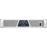
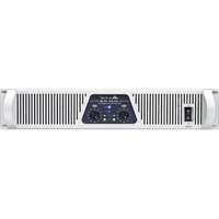
The MC500.4 Four Channels Power Amplifier is designed for professional use and provides unparalleled quality. It Includes soft start, signal limit, two variable-speed-low-noise fans and a LED meter display. Each channel is equipped with independent protective circuitry against open circuit, short circuit, mismatched loads and overheat. It includes four independent channels with separate power supply. Furthermore, every channel has also a main LED that becomes green for power-on indicator and green for muting or protection, another red LED that shows true amplifier clipping and a yellow one for the limit stage. The high-quality components and the carefully designed circuits ensure excellent audio performance and an extremely linear frequency response, giving crystal-clear sound in the high range and an up-front, full-bodied bottom end. This amplifier guarantees total reliability and a trouble-free use even in the most demanding conditions. We believe the MC500.4 not only look great, but provide a perfect performance, what you get is unprecedented performance at an incredibly attractive price.
2. FEATURE
• Innovative design and high stability power amplifier
• Fan-cooled AB class high power amplifier in 19", 2U size
• 4 independent channels with separate protection system
• DC, infrasonic, overheat & short circuit protection
• Smart-designed protection system for auto re-operation after fault
• Parallel-input: channel 1 to channel 2, channel 3 to channel 4
- Allow selection of Stereo, Bridge or parallel operation
• Ultra low-noise and hum
- High-pass filter, allow selection of flat, 35 Hz or 75Hz, protect speakers and prevent speaker transformer saturation with minimal effect on program material.
• DIP switch control for clip limit, high-pass filter, bridge-mono selections
• AUTO variable- speed-low-noise fans ensure high reliability even under demanding conditions.
- Detachable Euroblock: "Barrier strip" input connectors.
• Rugged amplifier in a strong, compact chassis
3. CONTROL ELEMENTS
3.1 The Front Panel

① Power Switch
It switches on / off MC500.4 main power.
② Power LED
This LED lights up when the amplifier is powered on
③ Input Level Indicator Display
There are three high accurate LED indicators, which shows the level of the input signal. When the respective channel's output signal distortion exceeds 0.5%, the red LED (clip) indicator lights up. it will warn you that the level of the input signal is too high and may cause distortion, please attenuate the level of the input signal.
④ Protection LED
This green LED indicator lights up when the amplifier is powered ON, indicating that the soft-start protection system is working. No sound is output during soft-start up. if one of the protection systems is activated during normal use, this indicator lights up and no sound is output. The speakers system is actually disconnected from the amplifier outputs when this indicator lights up. The protection systems are activated when overheating occurs or a DC voltage is corrected, the protection systems deactivate automatically, this indicator goes out, and normal amplifier operation is resumed.
⑤ Output Limiter LED
Set the clip limit switch at "ON" position, the yellow LED lights up when the unit is limiting the output signal.
⑥ Level Control
This pot provides smooth level changes control.
⑦ Fan
The unit is equipped with two fans, which can accelerate the flow of air to lower the temperature inside unit. The inside temperature determines the fan speed, which controls the inside air flowing speed.
⑧ Bridge Mode LED Indicator
When you operate the unit in bridge mode, the LED indicator lights up.
⑨ Parallel Mode LED Indicator
When you operate the unit power amplifier in parallel mode, the LED indicator lights up
3.2 The Rear Panel

⑩ INPUT Terminal
This unit is provided with balanced terminals, which are used to connect the input signal. Channel 1 and channel 3 are used in bridge and parallel mode.
⑪ Mode Selector
You can choose the right function and output you need via the mode selector switch. In order to make you acquire these settings, now let me introduce the dip switch.
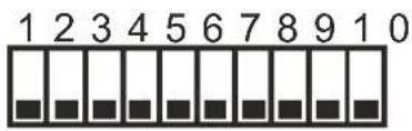
This switch is made up of 10 small dip switches, these small dip switches from 1 to 5 control one channel, these rest ones (6-10) control the other channel, ok, you can choose the right mode setting you need via these small dip switches. Take the dip switch of channel 1 and channel 2 for example. Channel 3 and channel 4 are the same as channel 1 and channel 2
- Output Mode Selector
This unit provides three output modes: stereo, bridge and parallel. Here are some details:
Stereo mode: turn these small dip switches of 4, 5, 6, 7 up to the top, then channel 1 and channel 2 are in stereo mode;

Parallel mode: turn these small dip switches of 4, 5, 6, to the top, and turn the small dip switch of 7 down, then channel 1 and channel 2 are in parallel mode.

Bridge mode: turn these small dip switch of 7 up to the top, then channel 1 and channel 2 are in bridge mode.
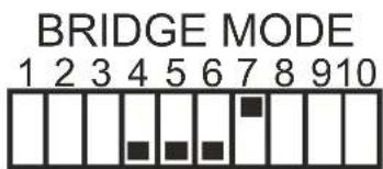
Please refer to chapter 5 for the connection of loads in detain.
- function selector
Clip limit : set these small dip switches of 1(ON) and 10(ON) at "ON" position, then the clip limit of channel 1 and channel 2 has been working; once the output level is reach or exceed the level that is predetermined by the threshold setting selected, it may result in the undesirable distortion .in order to avoid the distortion, the clip begins; if the dip switch are set at "OFF", the clip limit doesn't work.

Filter: this unit are equipped with two low cut filter eliminating unwanted low-frequency signals like rumble noise: 75Hz and 35Hz. You will activate 35Hz low cut filter by Turning these two small dip switches of 2 and 9 up to the top, and turn these two small dip switches down, you will choose 75Hz low cut filter.

bar
| Filter | Value | |---|---| | FILTER OFF | 1 | | 35Hz FILTER | 4 | | 75Hz FILTER | 5 | | FILTER OFF | 6 | | 35Hz FILTER | 7 | | FILTER ON | 10 |⑫ Output Terminal
You can output the powered signal by the specific output connectors according to the actual application circumstance.
Caution: turn off the unit before connecting the output connectors so as to avoid any electric shock!
⑬ Breaker
This switch works as fuse for protecting the unit from damage. When the unit is overloaded or the temperature inside the unit is too high, this push-button will spring up and break the power supply. The power supply will be restored with pushing this switch again.
⑭ AC-Inlet
This standard IEC receptacle is supplied to allow to connect your MC500.4 to mains via the supplied power cord.
4. Installation
4.1 Mains connection
Do not insert the power cord into this unit until voltage has been correctly set. Do not plug the power cord into the mains until the voltage has been correctly set. Please ensure that the MC500.4 professional power amplifi ris supplied with the correct voltage before turning on this unit. If you can't power up this unit while turning on the mains switch (1), check the Breaker (14) on the rear panel fist, maybe it is pressed to reset. Otherwise, contact the technician or qualified personnel for any service.
Caution: To reduce the risk of electric shock, do not perform any servicing other than contained in this manual unless you are qualified to do so. Please turn off this unit before any installation and connection, esp. when you connect your unit into the sound system. This is important to prevent damage to the unit itself as well as other consequent speaker system. This is important to prevent damage to the unit itself as well as other consequent speaker system. The mains connection of the MC 500.4 professional power amplifier is made by using the enclosed power cord and a standard IEC receptacle, and it meets all of the international safety certification requirement.
4.2 Rack Mounting
the most secure mounting is on a universal rack shelf available from various rack manufactures or your music dealer. The MC500.4 professional power amplifier fits into one standard 19" rack unit of space. Be sure that there is enough air space around the unit for sufficient ventilation. If heat release is inadequate, this unit will retain heat inside, which may cause the protection, or even a fire.
5. Application
The MC500.4 provides three operating modes with each unit: stereo mode, parallel mode and bridged mode, you can decide each specific operating mode according to your actual application circumstance. Following examples will show you the typical connections, you can refer to install your MC500.4 into a sound system:
5.1 Operate MC500.4 Power Amplifier In Stereo Mode
In this mode, channel 1 and channel 2 operate independently (as a conventional stereo amp). The channel 1 input signal will be output from the channel 1 output jacks, and the channel 2 input signal will be output from the channel 2 output jacks. (take channel 1 and channel 2 for example)

5.2 Operate MC500.4 Power Amplifier In Parallel Mode
in this mode, the channel 1 input signal will be output from the output connectors of both channel 1 and channel 2. The channel 2 input jack is not used. The channel 1 and channel 2 volumes can be adjusted independently.

5.3 Operate MC500.4 In Bridge Mode
In this mode, the channel 1 input signal will be output from the bridge output connectors. In this case, use the channel 1 volume control to adjust the volume. keep the volume control of channel 2 turned completely down (counterclockwise). Then, you can control the volume of the whole system by adjusting the channel 1 volume control.
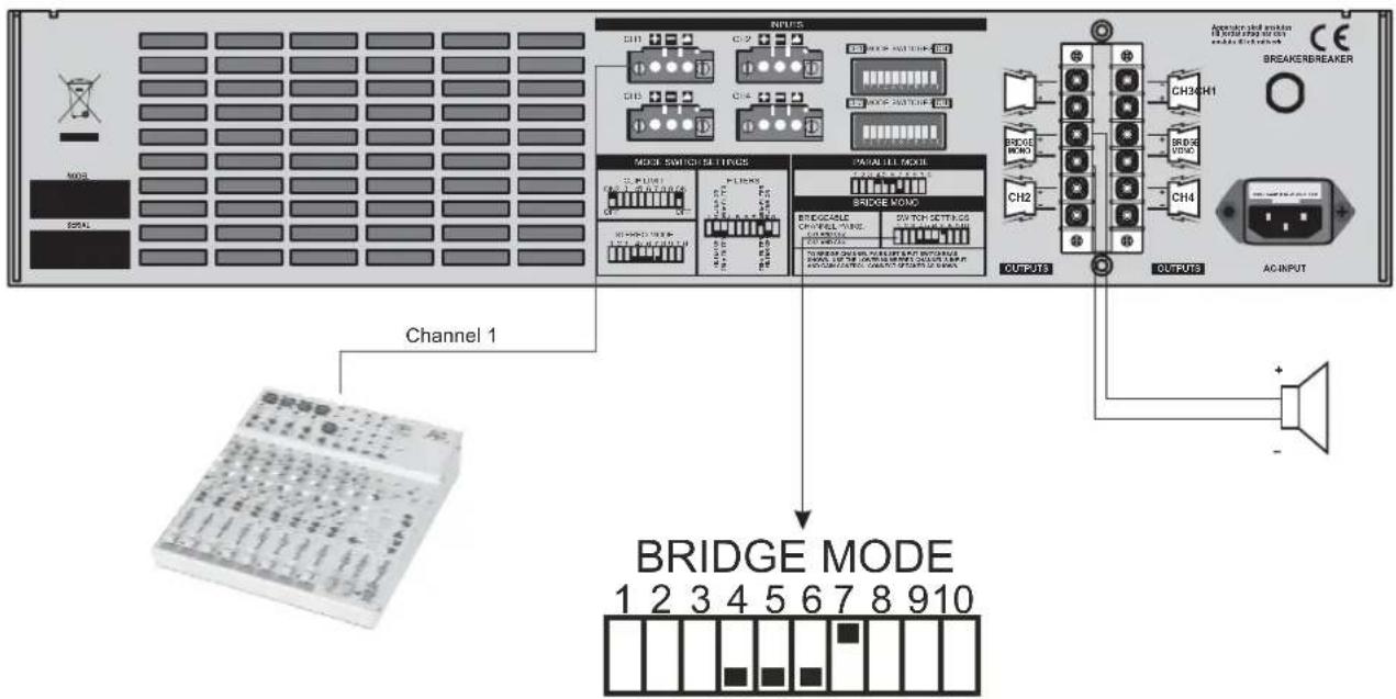
6.1 General Application instruction
the following instructions describe the common ways to install your MC500.4 power amplifier into a sound application system:
First, turn off power switch before connection.
Refer to chapter 5 for speaker connection
MC500.4 power amplifier may be operated in one of the three modes, please slide the mode selector for the specific operating mode
6.2 caution for speak connection
The output capacity of MC 500.4 power amplifier is very high, be sure to use a speaker system that has sufficient input capacity. If the input capacity of your speaker system is lower than the rated output of the MC500.4 power amplifier, you can protect your speakers by connecting a fuse serially between the speaker and the amplifier as shown below.
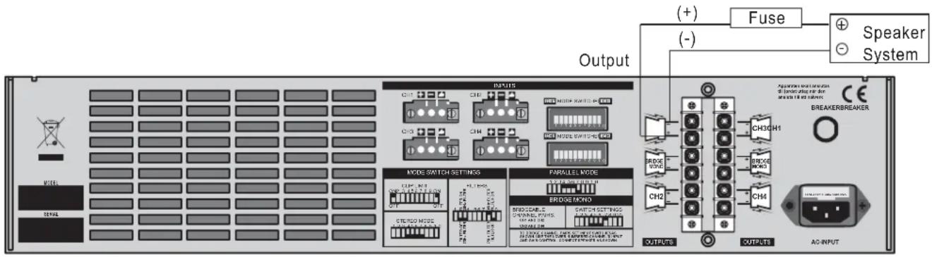
Use the following formula to determine the fuse capacity according to the speaker's input capacity.
$$ \mathrm{Po} = \mathrm{I} ^ {2} \mathrm{R} \longrightarrow \mathrm{I} = \sqrt {\mathrm{Po} / \mathrm{R}} $$
Po[W] : Speaker's continuous input capacity (noise or RMS)
R[Ω]: Speaker's nominal impedance
I[A] : Required fuse capacity
As to the speaker cable, if you use a long one, use as thick a cable as possible to prevent deterioration of the damping factor or power loss inside the cable.

flowchart
graph TD
    subgraph PT-MC500.4
        A["AC POWER"] --> B["CIRCUIT BREAKER"]
        B --> C["POWER SWITCH"]
        C --> D["PT-MC500.4"]
        D --> E["POWER 1 BRIDGE"]
        E --> F["CH1"]
        E --> G["POWER 2 BRIDGE"]
        G --> H["CH2"]
        G --> I["POWER 3 BRIDGE"]
        I --> J["CH3"]
        I --> K["POWER 4 BRIDGE"]
        K --> L["CH4"]
        D --> M["FAN BRIDGE"]
        M --> N["AC 17V"]
        N --> O["+12V"]
        O --> P["G1"]
    end

    subgraph MODE SWITCH Settings
        Q["CH1/CH2 MODE SWITCH"] --> R["3Hz/7Hz FILTER"]
        R --> S["CH1 LEVEL"]
        S --> T["CLIP"]
        T --> U["CH1 Heat Protection"]
        U --> V["CH1 AMP"]
        V --> W["CH1/CH2 OUTPUTS"]
        W --> X["CH1"]
        W --> Y["BRIDGE"]
        Y --> Z["CH2"]
        Y --> AA["CH3/CH4 MODE SWITCH"]
        AA --> AB["1 CLIP LIMIT-CH1"]
        AA --> AC["2 FILTER-ON/OFF-CH1"]
        AA --> AD["3 FILTER FEQ-CH1"]
        AA --> AE["4 PARALLEL+"]
        AA --> AF["5 PARALLEL-"]
        AA --> AG["6 PARALLEL-LED"]
        AA --> AH["7 BRIDGE ON/OFF"]
        AA --> AI["8 FILTER FEQ-CH2"]
        AA --> AJ["9 FILTER-ON/OFF-CH2"]
        AA --> AK["10 CLIP LIMIT-CH2"]

    subgraph MODE SWITCH Settings
        AR["1 CLIP LIMIT-CH3"] --> AS["2 FILTER-ON/OFF-CH3"]
        AR --> AT["3 FILTER FEQ-CH3"]
        AR --> AU["4 PARALLEL+"]
        AR --> AV["5 PARALLEL-"]
        AR --> AW["6 PARALLEL-LED"]
        AR --> AX["7 BRIDGE ON/OFF"]
        AR --> AY["8 FILTER FEQ-CH4"]
        AR --> AZ["9 FILTER-ON/OFF-CH4"]
        AR --> BA["10 CLIP LIMIT-CH4"]

    subgraph MODE SWITCH Settings
        ARB["1 CLIP LIMIT-CH3"] --> ASB["2 FILTER-ON/OFF-CH3"]
        ARB --> ATB["3 FILTER FEQ-CH3"]
        ARB --> AUW["4 PARALLEL+"]
        ARB --> AVW["5 PARALLEL-"]
        ARB --> AWW["6 PARALLEL-LED"]
        ARB --> AXW["7 BRIDGE ON/OFF"]
        ARB --> AYW["8 FILTER FEQ-CH4"]
        ARB --> AZW["9 FILTER-ON/OFF-CH4"]
        ARB --> BAW["10 CLIP LIMIT-CH4"]

    end

    subgraph MODE SWITCH Settings
        ARW["1 CLIP LIMIT-CH3"] --> AZW["2 FILTER-ON/OFF-CH3"]
        ARW --> AYW["3 FILTER FEQ-CH3"]
        ARW --> AZX["4 PARALLEL+"]
        ARW --> AZW["5 PARALLEL-"]
        ARW --> AZWW["6 PARALLEL-LED"]
        ARW --> AZWWW["7 BRIDGE ON/OFF"]
        ARW --> AZWZ["8 FILTER FEQ-CH4"]
        ARW --> AZWZW["9 FILTER-ON/OFF-CH4"]
        ARW --> AZWZWZ["10 CLIP LIMIT-CH4"]

    end
- TECHNICAL SPECIFICATION
| Model | MC500.4 |
| Output Power | |
| 20Hz 20kHz @0.1%THD, stereo Mode | |
| 8 ohms per channel (EIAJ) | 4x300W |
| 4 ohms per channel (EIAJ) | 4x500W |
| Bridge Mono Mode | |
| 8 ohms, 1kHz, 0.1% THD (EIAJ) | 2x1000W |
| Distortion (SMPTE-IM) | <0.05% |
| Frequency Response | 20Hz- 20kHz 1dB, -3dB point: 10Hz- 60kHz |
| Damping Factor, 1kHz, 0.1%THD(EIAJ) | >300@8 ohms |
| Signal to Noise, 20Hz-20kHz | 100dB |
| Voltage Gain | 40×(32dB) |
| Input sensitivity @ 4 ohms | 1Vrms |
| Input clipping | 10 Vrms (+22dB) |
| Input impedance | 10Kohms unbalanced, 20 Kohms balanced |
| Controls | Front: AC Switch, Ch1 - Ch4 Gain Knobs |
| Rear: MODE SWITCHS | |
| Indicators | Power - On: Blue LED |
| Protection: Green LED | |
| LIMITER: Yellow LED | |
| Clip: Red LED | |
| Parallel-input: Yellow LED | |
| Bridge: Yellow LED | |
| Level: Green LED (-20 and -10dB) | |
| Connectors, each channel | Input: Terminal Block |
| Output: Screw-terminal Barrier Block | |
| cooling | Continuously variable- speed fan, front - to - rear air flow |
| Load protection | On / Off muting, overheat & short circuit protection |
| Power supply | 220-240 (110-120) Vac 50-60 Hz |
| Dimensions | 19" (48.3 cm) rack mounting, 3.5" (8.9 cm) tall (2 racks pace 15.9" (40.3 cm) deep (rack mounting to rear support ears) |
| Net weight | 19Kg |
9. WARRANTY
1. WARRANTY REGISTRATION CARD
To obtain Warranty Service, the buyer should first fill out and return the enclosed Warranty Registration Card within 10 days of the Purchase Date.
All the information presented in this Warranty Registration Card gives the manufacturer a better understanding of the sales status, so as to purport a more effective and efficient after-sales warranty service.
Please fill out all the information carefully and genuinely, miswriting or absence of this card will void your warranty service.
2. RETURN NOTICE
2.1 In case of return for any warranty service, please make sure that the product is well packed in its original shipping carton, and it can protect your unit from any other extra damage.
2.2 Please provide a copy of your sales receipt or other proof of purchase with the returned machine, and give detail information about your return address and contact telephone number.
2.3 A brief description of the defect will be appreciated.
2.4 Please prepay all the costs involved in the return shipping, handling and insurance.
3. TERMS AND CONDITIONS
3.1 ▲LTO warrants that this product will be free from any defects in materials and/or workmanship for a period of 1 year from the purchase date if you have completed the Warranty Registration Card in time.
3.2 The warranty service is only available to the original consumer, who purchased this product directly from the retail dealer, and it can not be transferred.
3.3 During the warranty service, ▲LTO may repair or replace this product at its own option at no charge to you for parts or for labor in accordance with the right side of this limited warranty.
3.4 This warranty does not apply to the damages to this product that occurred as the following conditions:
• Instead of operating in accordance with the user's manual thoroughly, any abuse or misuse of this product.
- Normal tear and wear.
- The product has been altered or modified in any way.
- Damage which may have been caused either directly or indirectly by another product / force / etc.
- Abnormal service or repairing by anyone other than the qualified personnel or technician.
And in such cases, all the expenses will be charged to the buyer.
3.5 In no event shall ▲LTO be liable for any incidental or consequential damages. Some states do not allow the exclusion or limitation of incidental or consequential damages, so the above exclusion or limitation may not apply to you.
3.6 This warranty gives you the specific rights, and these rights are compatible with the state laws, you may also have other statutory rights that may vary from state to state.
SEIKAKU TECHNICAL GROUP LIMITED
SEKAKU ELECTRON INDUSTRY CO., LTD.
No. 1, Lane 17, Sec. 2, Han Shi West Road, Taichung 40151, Taiwan
http://www.altoproaudio.com Tel: 886-4-22313737
email: alto@altoproaudio.com Fax: 886-4-22346757
All rights reserved to ALTO. All features and content might be changed without prior notice. Any photocopy, translation, or reproduction of part of this manual without written permission is forbidden. Copyright © 2005 SEIKAKU GROUP



- SAFETY RELATED SYMBOLS
- WARNING
- CAUTION
- - Power Supply
- - External Connection
- - Do Not Remove Any Covers
- Covers should be removed by qualified service personnel only.
- - Fuse
- - Protective Ground
- - Operating Conditions
- IMPORTANT SAFETY INSTRUCTIONS
- • Power Cord and Plug
- - Cleaning
- - Servicing
- PREFACE
- TABLE OF CONTENTS
- INTRODUCTION
- FEATURE
- CONTROL ELEMENTS
- The Front Panel
- The Rear Panel
- ⑩ INPUT Terminal
- ⑪ Mode Selector
- - Output Mode Selector
- - function selector
- ⑫ Output Terminal
- ⑬ Breaker
- ⑭ AC-Inlet
- Installation
- Mains connection
- Rack Mounting
- Application
- Operate MC500.4 Power Amplifier In Stereo Mode
- Operate MC500.4 Power Amplifier In Parallel Mode
- Operate MC500.4 In Bridge Mode
- General Application instruction
- caution for speak connection
- WARRANTY
- WARRANTY REGISTRATION CARD
- RETURN NOTICE
- TERMS AND CONDITIONS
Brand : ALTO
Model : MC500.4
Category : Receiver