
DIN-EN-3X18 - Lighting Crestron - Free user manual and instructions
Find the device manual for free DIN-EN-3X18 Crestron in PDF.


| Product Type | 3-Channel Audio Amplifier |
| Brand | Crestron |
| Model | DIN-EN-3X18 |
| Dimensions (H x W x D) | 4.2 x 3.5 x 1.6 inches (107 x 89 x 41 mm) |
| Weight | 0.55 lbs (0.25 kg) |
| Power Supply | 24V DC, 1A (power supply not included) |
| Channels | 3 |
| Output Power per Channel | 18W RMS into 8 ohms |
| Input Impedance | 10 kΩ balanced |
| Frequency Response | 20 Hz – 20 kHz ±1 dB |
| Signal-to-Noise Ratio | > 90 dB |
| Input Connectors | 3x Phoenix-style screw terminals |
| Output Connectors | 3x speaker binding posts or Phoenix terminals |
| Mounting | DIN rail mount (EN 50022) |
| Operating Temperature | 32°F to 104°F (0°C to 40°C) |
| Certifications | CE, FCC Class B |
| Application | Commercial audio distribution, paging systems |
| Cleaning Instructions | Wipe with dry cloth; do not use liquid cleaners |
| Safety Notice | Disconnect power before servicing; use only supplied voltage |
| Spare Parts Availability | Contact Crestron for replacement parts |
Frequently Asked Questions - DIN-EN-3X18 Crestron
User questions about DIN-EN-3X18 Crestron
0 question about this device. Answer the ones you know or ask your own.
Ask a new question about this device
Download the instructions for your Lighting in PDF format for free! Find your manual DIN-EN-3X18 - Crestron and take your electronic device back in hand. On this page are published all the documents necessary for the use of your device. DIN-EN-3X18 by Crestron.
USER MANUAL DIN-EN-3X18 Crestron
Crestron Electronics, Inc
Crestron product development software is licensed to Crestron dealers and Crestron Service Providers (CSPs) under a limited non-exclusive, non transferable Software Development Tools License Agreement. Crestron product operating system software is licensed to Crestron dealers, CSPs, and end-users under a separate End-User License Agreement. Both of these Agreements can be found on the Crestron website at www.crestron.com/legal/software_license_agreement.
The product warranty can be found at www.crestron.com/warranty.
The specific patents that cover Crestron products are listed at patents.crestron.com.
Certain Crestron products contain open source software. For specific information, please visit www.crestron.com/opensource.
Crestron, the Crestron logo, 3-Series, 3-Series Control System, Cameo, CREScode, Cresnet, Crestron Fusion, Crestron Green Light, and Smart Graphics are either trademarks or registered trademarks of Crestron Electronics, Inc. in the United States and/or other countries. Life Safety Code and National Electrical Code are either trademarks or registered trademarks of the National Fire Protection Association (NFPA) in the United States and/or other countries. UL is either a trademark or registered trademark of Underwriters Laboratories, Inc. in the United States and/or other countries. DALI is either a trademark or registered trademark of ZVEI-Zentralverband Elektrotechnik-; und Elektronikindustrie e.V. Eingetragener Verein in the United States and/or other countries. Other trademarks, registered trademarks, and trade names may be used in this document to refer to either the entities claiming the marks and names or their products. Crestron disclaims any proprietary interest in the marks and names of others. Crestron is not responsible for errors in typography or photography.
This document was written by the Technical Publications department at Crestron.
©2017 Crestron Electronics, Inc.
Contents
Introduction 1
Crestron and DALI-AG Working Group ....1
DALI Requirements ....3
Emergency and DALI Drivers....4
Crestron Fusion® Software and DALI 5
DALI Commissioning Tool 6
Crestron DALI Related Products 8
Crestron DALI Control Systems....8
DIN Enclosures....9
GL-EXP Series....10
Crestron DALI Accessories 12
DIN-DALI-2 Interface 13
DALI LED Drivers 14
DALI Loop Wiring 16
DALI Application Examples 17
Individual Office 17
Multiple Offices....18
Conference Room 19
Training Room....20
Glossary of Terms 21
Introduction
Digital Addressable Lighting Interface (DALI ^® ) systems should be used where driver-level control is required. DALI is ideal for open space commercial environments. When cubicle and workspace layouts change, the lighting can be regrouped and adjusted as needed. Other typical applications include college lecture halls, hospital operating rooms, and corporate conference rooms. DALI provides tremendous flexibility for both retrofit and new installations. When lamps and drivers are replaced on a DALI system, the wiring stays the same and the DIN-DALI-2 readdresses the new driver with the address and parameters of the original driver.
Crestron® control systems seamlessly connect with the open DALI protocol by way of the DIN-DALI-2 interface. The DIN-DALI-2 interface can work with any Crestron control system as well as any power supply. Crestron devices such as keypads, thermostats, photo and occupancy sensors, gateways, and other Cresnet® devices can easily communicate with the DALI system.
Commissioning lighting groups, detecting faults, and replacing drivers are simple when using the powerful Crestron DALI Commissioning Tool. The user can develop interactive floor plans using Smart Graphics® software, which provides easier monitoring, management, and control of all the light fixtures within the space.
Crestron delivers the most comprehensive DALI driver solutions with 1-, 2-, and 3-lamp versions available for any application, in any part of the world. Crestron Green Light® DALI drivers support dimming a wide range of lamps from 1 to 100% . DALI drivers are the most comprehensive driver solution on the market today. The DALI drivers drive multiple lamp wattages in one unit, which makes lighting design easier and less expensive.
The new line of Crestron dimmable LED drivers provides high-power LED lighting with deep dimming to below 1%. Available in 50 W and 100 W models with DALI control, GLD-LED drivers offer superior, smooth dimming technology using a combination of duty-cycle and current dimming.
The optional built-in power metering feature is unique to Crestron DALI drivers. The ability to measure, monitor, and manage power to each light fixture, while enabling daylight harvesting and load shedding, makes it easy to implement a fully integrated system that combines architectural lighting control and energy management all on one platform. Optional power metering models track real-time energy usage of each load and provide essential statistics to help manage and control utility costs.
For more information on DALI systems, refer to the Commercial Lighting webpage on the Crestron website.
Crestron and DALI-AG Working Group
Crestron is a participating member of the DALI-AG Working Group. Participating members are key suppliers of products and technology that comply with DALI and IEC 62386 standards. As a member, Crestron participates in committee proceedings and plays a role in the development of specifications. Members have total access to all DALI specifications, which are critical to the development of products.
The example below shows how Crestron products communicate with DALI and other building systems.
Communicating with DALI

flowchart
graph TD
    A["Control System Components in Electrical Closet"] --> B["LAN"]
    B --> C["Building Management System"]
    C --> D["TOUCH SCREEN"]
    D --> E["KEYPAD"]
    E --> F["OCCUPANCY SENSOR"]
    F --> G["PHOTOCELL SENSOR"]
    G --> H["Up to 64 Drivers"]
    H --> I["DAU DRIVER"]
    I --> J["Control Wire to Lighting Fixture"]
    J --> K["DAI Driver"]
    K --> L["Up to 64 Drivers"]
    L --> M["DAU Driver"]
    M --> N["Control Wire to Lighting Fixture"]
    N --> O["DAI Driver"]
    O --> P["Up to 64 Drivers"]
    P --> Q["DAU Driver"]
    Q --> R["Control Wire to Lighting Fixture"]
    R --> S["DAI Driver"]
    S --> T["Up to 64 Drivers"]
    T --> U["DAU Driver"]
    U --> V["Control Wire to Lighting Fixture"]
    V --> W["DAI Driver"]
    W --> X["Up to 64 Drivers"]
    X --> Y["DAU Driver"]
    Y --> Z["Control Wire to Lighting Fixture"]
    Z --> AA["DAI Driver"]
    AA --> AB["Up to 64 Drivers"]
    AB --> AC["DAU Driver"]
    AC --> AD["Control Wire to Lighting Fixture"]
    AD --> AE["DAI Driver"]
    AE --> AF["Up to 64 Drivers"]
DALI is a protocol used for the direct control of lighting drivers. The DALI standard allows multiple drivers to be daisy-chained using low-voltage wiring for powering on or off and dimming control. Up to 64 independently operating drivers can exist on a single DALI loop. DALI lighting is optimal for applications that require granular control of each fixture, such as open office floor plans and daylight harvesting in classrooms.
Topology free Class 1 or Class 2 DALI control wiring techniques may be used, which are much simpler than wiring in 0 to 10 V dimming systems. DALI systems can report driver failures for easier maintenance and, with Crestron PM drivers, controllers can query energy usage. Additionally, the DALI data is resistant to noise, which allows it to run alongside line-voltage power lines. The Crestron DALI Commissioning Tool simplifies system installation and provides a setup wizard with step-by-step configuration of driver properties, groups, and scenes.
Spaces with changing tenants and large campuses with frequently repurposed rooms are the prime target of DALI systems. Some of the key features are as follows:
- Individual Addresses: Each DALI driver has its own unique address on the system; therefore, the system is able to communicate with each driver independently of the others.
- Number of Addresses: Up to 64 addresses can be on one DALI loop. An unlimited number of loops can be placed on a complete DALI networked system.
- Grouping: DALI drivers can be assigned to 1–16 groups on a loop, without the need for rewiring.
- Bidirectional Communication: Drivers are able to receive information as well as report lamp or driver failures to the central DALI system.
- Readdressing Drivers: If a driver fails on a system, the loop can detect the missing address and readdress it when a new driver is added back in its place.
- Warranty and Compliance: Crestron DALI drivers include a 5-year warranty. The drivers are UL ^® listed, are CE marked, and follow the RoHS Compliant directive.
DALI Requirements
The intent of the DALI protocol is to supply low-cost, interchangeable drivers that are simple to program and commission. DALI requirements are shown below:
- Driver Power Requirements: Drivers must provide universal voltage (115 to 300 V), 50 to 60 Hz, high-power factor, low harmonics, and transient surge protection. When the initial voltage is applied, the lamps go to full on or to a preset level.
- Command Requirements: Drivers are able to receive information and report this information back to the central DALI system regarding lamp or driver failures.
- Lamp Response Requirements: DALI protocol requires a precise logarithmic dimming curve of 254 steps (2.8 % increase per step) so that all drivers dim the same: 0 to 100% for incandescent and fluorescent, 3 to 100% for compact fluorescent, and 0 to 100% for LED.
- Protocol Requirements: The DALI protocol requirements include the intent and electrical requirements of the protocol, bits and bytes requirements, collision detection, and the type of wire to be used for the DALI system.
Emergency and DALI Drivers
Crestron DALI drivers comply with open DALI standards. When the DALI signal is lost or the DIN-DALI-2 override port is triggered, the driver goes to an emergency state (100% ON by default.) This complies with the National Electrical Code® and Life Safety Code® (NFPA 101) standards, as well as many other state and local codes.
In the example below, five of the six fixtures are fed with a normal power source. One of the fixtures is fed with an emergency power source. The Class I or Class II DALI wiring can loop through normal and emergency fixtures.
Emergency Driver-Powering Scenario

flowchart
graph TD
    A["DIN-DALI-2"] --> B["DALI+"]
    B --> C["Ethernet to Central Processor"]
    D["External System"] --> E["Internal Components"]
    E --> F["Color Key"]
    F --> G["DALI +"]
    F --> H["DALI -"]
    F --> I["Ethernet"]
    style A fill:#f9f,stroke:#333
    style D fill:#ccf,stroke:#333
    style E fill:#cfc,stroke:#333
    style F fill:#fcc,stroke:#333
    style G fill:#ffc,stroke:#333
    style H fill:#cfc,stroke:#333
    style I fill:#fcc,stroke:#333
Crestron Fusion® Software and DALI
Crestron Fusion is a simple-to-use, web-based energy management interface and facility control solution. When Crestron Fusion and DALI are used together, the following can be performed:
- Track the real-time and historical energy usage for a day, week, month, or year.
• View the room statuses for an entire facility. - Define the settings for occupied and unoccupied states.
- Reduce the energy loads for demand response programs.
- Maintain full control of lighting levels, shades, and climate.
- Interface with a Building Management Systems (BMS) for HVAC control and automation.
The Crestron Fusion server application allows the user to view driver failures communicated via the open DALI protocol. The example below shows the way in which the Crestron Fusion application pinpoints a driver failure.
Summary View Screen Displaying Driver Failure in Crestron Fusion

DALI Commissioning Tool
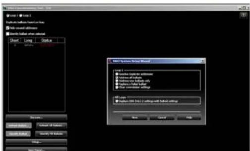
The Crestron DALI Commissioning Tool expedites system installation. The commissioning tool includes a setup wizard that provides step-by-step instructions to configure driver properties, groups, and scenes. Simply complete the following steps:
- Set the driver address.
- Check the connectivity status.
- Edit the minimum and maximum levels and fade time.
- Change the driver grouping and scenes as needed.
This powerful tool uses automatic identification of new hardware IDs for simple driver replacement. Settings from old drivers are transferred to replacements, which saves time and eliminates guesswork.
DALI Commissioning Tool Screen

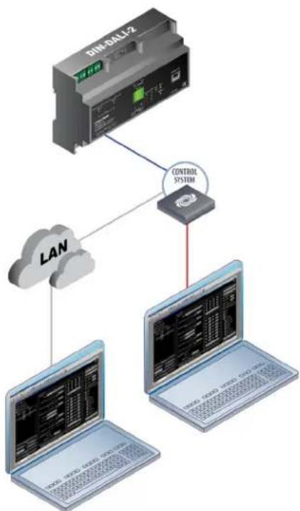
Depending upon the application, there are multiple methods for commissioning a DALI system network. Several methods of connecting to a DIN-DALI-2 are shown below.
DIN-DALI-2 Over a LAN

flowchart
graph TD
    A["DM-SALI2 Server"] --> B["Laptop"]
    B --> C["LAN"]
    C --> A
DIN-DALI-2 Direct Connection
Over a USB

flowchart
graph TD
    A["DM-0XL12 Device"] --> B["USB"]
    B --> C["Laptop with network interface"]
DIN-DALI-2 Over a LAN Using a Touch Screen

flowchart
graph TD
    A["SIM-CELL2"] --> B["LAN"]
    B --> C["Tablet"]
DIN-DALI-2 Over a LAN Using a Control System
flowchart
graph TD
    A["DIM-DALI-2"] --> B["LAN"]
    A --> C["CONTROL SYSTEM"]
    B --> D["Laptop with network interface"]
    C --> E["Laptop with network interface"]
DIN-DALI-2 Over a LAN and Wireless LAN

flowchart
graph TD
    A["DIN-DALI-2"] -->|LAN| B["Wireless LAN"]
    B -->|Wi-Fi| C["Laptop with network"]
    C -->|Mobile Device Controller| D["Desktop"]
Crestron DALI Related Products
Crestron DALI Control Systems
The Crestron products below can be used to control a basic DALI control system.

DIN-DALI-2: The DIN-DALI-2 is a DALI interface for Crestron systems that provides control for up to two individual DALI loops.
DIN-AP3: The DIN-AP3 is a 3-Series ^® control processor designed for small- to medium-sized lighting and automation applications.
DIN-PWS50: The DIN-PWS50 is a 50 W Cresnet power supply module designed to snap onto a standard DIN rail for installation in a wall mount enclosure.
NOTE: For more information on DALI control systems, refer to the Crestron website at www.crestron.com.
DIN Enclosures
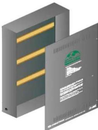
The DIN-EN Series of metal panels are designed to house up to 18 DIN rail devices per panel. Each enclosure includes a removable front cover for easy access to the equipment. A DIN-EN Series panel is the perfect enclosure for Crestron DIN rail products such as the DIN-AP3 and DIN-DALI-2.

natural_image
3D rendering of a gray rectangular electronic device with yellow internal bands and a separate flat panel with green logo (no visible text or symbols on the device itself)DIN-EN-2X18: The DIN-EN-2X18 is an enclosure that is used for DIN rail devices (two DIN rails and 18 units wide). The enclosure dimensions are Height: 12.32 in (323 mm), Width: 14.13 in (359 mm), and Depth: 4.38 in (111 mm).
natural_image
Illustration of two gray rectangular electronic devices with gold leads and a green logo on the cover (no text or symbols visible)DIN-EN-3X18: The DIN-EN-3X18 is an enclosure that is used for DIN rail devices (three DIN rails and 18 units wide). The enclosure dimensions are Height: 23.50 in (597 mm), Width: 14.38 in (366 mm), and Depth: 4.44 in (113 mm).

natural_image
Illustration of two gray server racks with yellow and green slats, one open showing a closed panel (no text or symbols visible)DIN-EN-6X18: The DIN-EN-6X18 is an enclosure that is used for DIN rail devices (six DIN rails and 18 units wide). The enclosure dimensions are Height: 38.88 in (989 mm), Width: 14.38 in (366 mm), and Depth: 4.44 in (113 mm).
NOTE: For more information on DIN enclosures, refer to the DIN-EN page on the Crestron website.
GL-EXP Series
The Crestron Green Light GL-EXP Series are professional lighting control modules for DALI based lighting systems. These products are designed for easy installation on a wall or above a suspended ceiling and are a perfect solution for adding extra lighting zones to any system without requiring an additional lighting cabinet. The modules below communicate using the DALI protocol. Utilizing proprietary zero-cross filter technology, the Crestron Green Light products below compensate for line voltage and frequency fluctuations, providing immunity to power line noise and reduction in lamp flicker.

GL-EXP-SW-DALI: A single-channel expansion module that is controlled by DALI. The GL-EXP-SW-DALI provides switching for incandescent, magnetic and electronic low-voltage, neon and cold cathode, fluorescent driver, high-intensity discharge, LED, and motor loads. The load rating is 16 A. The dimensions are Height: 8.75 in (223 mm), Width: 6.36 in (163 mm), and Depth: 3.19 in (81 mm).

GL-EXP-DIM-DALI: The GL-EXP-DIM-DALI is a single-channel dimmer expansion module designed to control LED, magnetic low-voltage, incandescent, neon and cold cathode, and 2-wire dimmable fluorescent lighting loads. The load rating is 16 A. The dimensions are Height: 8.75 in (223 mm), Width: 6.36 in (163 mm), and Depth: 3.19 in (81 mm).

GL-EXP-DIMU-DALI: The GL-EXP-DIMU-DALI is a single-channel universal dimmer expansion module designed to control electronic and magnetic low-voltage, LED, incandescent, neon/cold cathode, 2-wire dimmable fluorescent, and nondimmable lighting loads. The load rating is 16 A. The dimensions are Height: 8.75 in (223 mm), Width: 6.36 in (163 mm), and Depth: 3.19 in (81 mm).
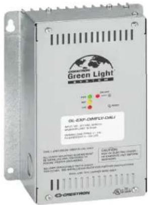
GL-EXP-DIMFLV-DALI: The GL-EXP-DIMFLV-DALI is a single-channel dimmer expansion module designed to dim 0–10 V drivers can be used to switch nondimmable loads. The load rating is 16 A. The dimensions are Height: 8.75 in (223 mm), Width: 6.36 in (163 mm), and Depth: 3.19 in (81 mm).

GL-EXP-DIMFDB-DALI: The GL-EXP-DIMFDB-DALI is a single-channel expansion module controlled by DALI that provides dimming control for 0–10 V drivers. The load rating is 16 A. The dimensions are Height: 8.75 in (223 mm), Width: 6.36 in (163 mm), and Depth: 3.19 in (81 mm).
NOTE: For more information on GL-EXP Series lighting control modules, refer to the Crestron website at www.crestron.com.
Crestron DALI Accessories
The Crestron occupancy sensors, photocell sensors, keypads, and touch screens below can be used to control a basic DALI control system.

Occupancy Sensors: Crestron sensors deliver a powerful and cost-effective solution for reducing energy and enhancing the functionality of lighting and environmental systems. The GLS-ODT-C-CN model is shown.
Photocell Sensors: Photocell sensors are designed for daylight harvesting applications to provide control of room lighting based on the presence of natural daylight. The GLS-LCL (left) and GLS-LOL (right) models are shown.
Keypads: Crestron offers a wide array of elegant designer keypads for home, education, and corporate environments. Keypads provide the user with control of preset lighting scenes and dimming. The C2N-CBD-P Cameo® keypad wall mount models are shown.
Touch Screens: Crestron delivers the maximum value to the customer as the premier source for touch screens. The TSW-1060 10.1 in touch screen display is shown.
DIN-DALI-2 Interface
The DIN-DALI-2 is a DALI interface for Crestron systems that provides control of up to two independent DALI loops. Housed in a DIN rail enclosure, the DIN-DALI-2 is a low-profile Ethernet companion to the DIN-AP3 processor or any 3-Series Control System® device. In addition to controlling the DALI data bus, it includes an integrated DALI power supply. The single-wire connectivity simplifies both new and retrofit installations. Power-over-Ethernet (PoE) versatility assists in situations with existing CAT5 infrastructure:
• Cresnet or PoE communication for single-wire installation
- Crestron DALI Commissioning Tool for easy setup
• DIN rail mounting 9 M wide
• CEC Title 24 2013 compliant
For the DALI protocol to communicate with other protocols, a control interface is necessary. The interface acts as a language translator, allowing the DALI protocol to be understood and used by other protocols such as Cresnet, BACnet, and Ethernet. Using the DALI protocol, the primary building systems can easily communicate. The DIN-DALI-2 is powered through either Cresnet or PoE. This simplifies wiring to the DIN-DALI-2 module.
DIN-DALI-2

NOTE: For more information, refer to the DIN-DALI-2 product page on the Crestron website.
DALI LED Drivers
Crestron dimmable LED drivers provide high-power LED lighting with deep dimming to below 1%. The 50 W and 100 W models afford high-power capability for use with a wide range of LED fixtures.
Crestron LED Drivers (GLD-LED) provide manufacturers of dimmable LED lighting fixtures with a high-performance, cost-saving LED driver solution. Offered in two compact case styles, the GLD-LED series fits easily into a wide range of enclosures and fixture designs. All models are operable between 120 V and 277 V, reducing inventory costs for manufacturers serving multiple regions.
Models featuring DALI control are available in either 1- or 2-channel configurations. The 2-channel models support tunable white lighting and direct-indirect fixtures.
Crestron Green Light Dimmable LED Drivers are programmable using the CREScode® LED Driver Configuration Tool, allowing each LED driver to be matched perfectly to its fixture at the factory. The configuration tool provides a simple means of selecting the dimming curve and setting the minimum dimming level, NTC temperature, and output current. The output current can be set individually for each LED output. The use of programmable LED drivers reduces inventory requirements, allowing a single driver model to be used with numerous different fixtures.
The compatible 50 W DALI dimmable LED driver models are the GLD-DALI-LED-L-1X50W, GLD-DALI-LED-S-1X50W, GLD-DALI-LED-L-2X50W, and GLD-DALI-LED-S-2X50W.
The compatible 100 W DALI dimmable LED driver models are the GLD-DALI-LED-L-1X100W, GLD-DALI-LED-S-1X100W, GLD-DALI-LED-L-2X100W, and GLD-DALI-LED-S-2X100W.
GLD-DALI-LED-S-1X50W
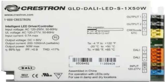
GLD-DALI-LED-L-1X50W

GLD-DALI-LED-S-2X100W
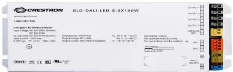
GLD-DALI-LED-L-1X100W

NOTE: For more information, refer to the GLD-LED product page on the Crestron website.
DALI Loop Wiring
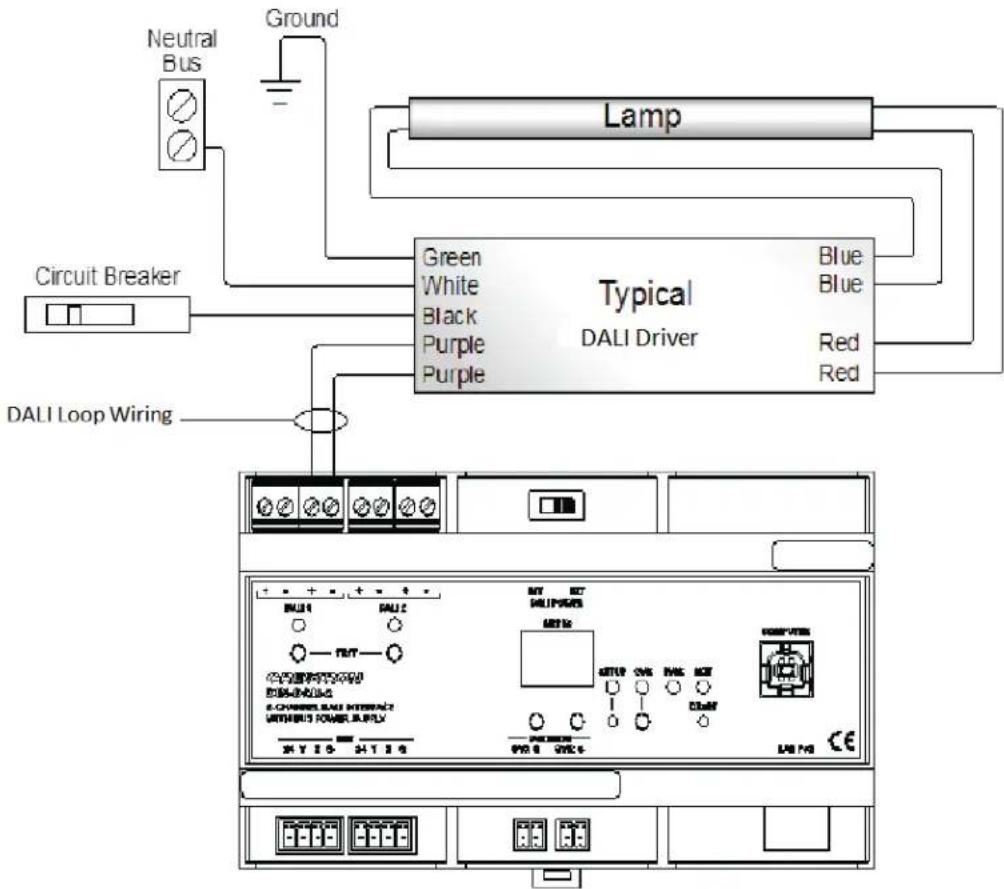
Class I DALI in MC or EMT does not require a shielded wire. When Class II DALI is installed in free air, Crestron recommends using a shielded cable to minimize induced voltage degradation and interference. DALI wire is sized appropriately based upon voltage drop due to cable length. Crestron recommends 16 or 18 AWG based upon cable length. The DALI protocol standard can communicate up to 980 ft (300 m). Per the NEC, class 1 DALI wire may be run in the same conduit as line voltage wire.
DALI Loop Wiring Example
flowchart
graph TD
    A["Circuit Breaker"] --> B["Neutral Bus"]
    B --> C["Ground"]
    C --> D["Lamp"]
    D --> E["Typical DALI Driver"]
    E --> F["DALI Loop Wiring"]
    F --> G["DC Power Supply"]
    G --> H["Ground"]
    style A fill:#f9f,stroke:#333
    style B fill:#ccf,stroke:#333
    style C fill:#cfc,stroke:#333
    style D fill:#fcc,stroke:#333
    style E fill:#cff,stroke:#333
    style F fill:#ffc,stroke:#333
    style G fill:#cfc,stroke:#333
    style H fill:#fcc,stroke:#333
DALI Application Examples
The examples in this section show how a DALI control system can be utilized in an individual office, open office, conference room, and training room.
Individual Office
Daylight and room occupancy sensors can be easily added when a DALI control system is used to control lighting fixtures.
In the individual office example below, the fixture closer to the window is dimmed lower than the one further from the window based on the amount of natural light. The photo sensor measures the outdoor light while the occupancy sensor determines if the room is in use. The Cameo keypad provides the user with control of preset lighting scenes and dimmer control.
Individual Office Using a DALI Control System

flowchart
graph TD
    A["DIN-AP3"] --> B["DIN-DALI-2"]
    B --> C["DALI Control"]
    C --> D["Cresnet to Central Processor (Optional)"]
    D --> E["Occupancy Sensor"]
    E --> F["Photocell Sensor"]
    F --> G["Cresnet"]
    G --> H["DALI Control"]
    style A fill:#f9f,stroke:#333
    style B fill:#ccf,stroke:#333
    style C fill:#cfc,stroke:#333
    style D fill:#fcc,stroke:#333
    style E fill:#ffc,stroke:#333
    style F fill:#fcc,stroke:#333
    style G fill:#ffc,stroke:#333
    style H fill:#cff,stroke:#333
Multiple Offices
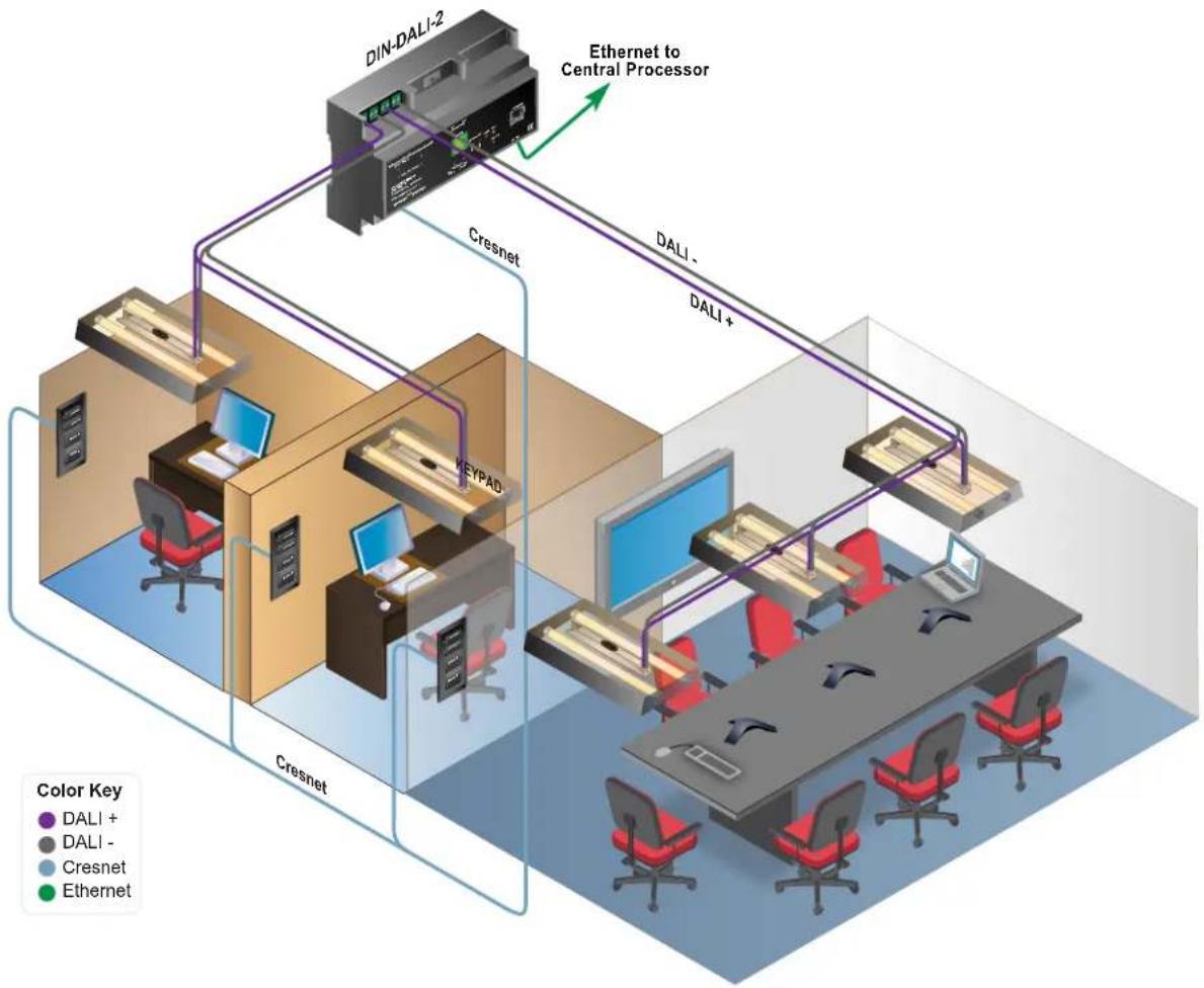
During the installation of a DALI control system (in large office spaces), wiring across multiple units decreases installation time. The ability to move light fixtures around the grid without the need to rerun wire becomes invaluable.
The example below shows how a DALI control system can be utilized within a multiple office setting.
Multiple Offices Using a DALI Control System
flowchart
graph TD
    A["Cresnet"] -->|Ethernet to Central Processor| B["DIN-DALI-2"]
    B -->|DALI -| C["KeyPAD"]
    C -->|DALI +| D["DALI"]
    D --> E["Cresnet"]
    E --> F["Computer"]
    F --> G["Laptop"]
    G --> H["Office 1"]
    F --> I["Office 2"]
    style A fill:#f9f,stroke:#333
    style B fill:#ccf,stroke:#333
    style C fill:#cfc,stroke:#333
    style D fill:#fcc,stroke:#333
    style E fill:#ffc,stroke:#333
    style F fill:#cff,stroke:#333
    style G fill:#ffc,stroke:#333
    style H fill:#cfc,stroke:#333
    style I fill:#fcc,stroke:#333
Conference Room
Each light fixture is controlled through the DALI control system. A photocell and occupancy sensor are incorporated into the system. Keypads connected to the Cresnet bus provide scene recall and zone control.
The example below shows how a DALI control system can be utilized in a conference room setting.
Conference Room Using a DALI Control System

flowchart
graph TD
    A["DIN-AP3"] --> B["Occupancy Sensor"]
    C["DIN-DALI-2"] --> B
    B --> D["Cresnet to Central Processor (Optional)"]
    D --> E["DALI Control"]
    E --> F["Daylight Sensor"]
    F --> G["Cresnet"]
    G --> H["KEYPAD"]
    I["DALI Control"] --> J["Occupancy Sensor"]
    K["Daylight Sensor"] --> L["Cresnet"]
    M["Occupancy Sensor"] --> N["Cresnet"]
    O["Cresnet"] --> P["Cresnet"]
    style A fill:#f9f,stroke:#333
    style C fill:#f9f,stroke:#333
    style I fill:#f9f,stroke:#333
    style K fill:#f9f,stroke:#333
    style M fill:#f9f,stroke:#333
    style O fill:#f9f,stroke:#333
Training Room
Each light fixture is controlled directly from the grid with each row of lights controlled by a separate channel on the DALI control system. One channel dims the row closest to the windows while the second channel dims the other row. Both a photocell and occupancy sensor are connected to the DALI control system for energy savings.
The example below shows how a DALI control system can be utilized in a training room setting.
Training Room Using a DALI Control System
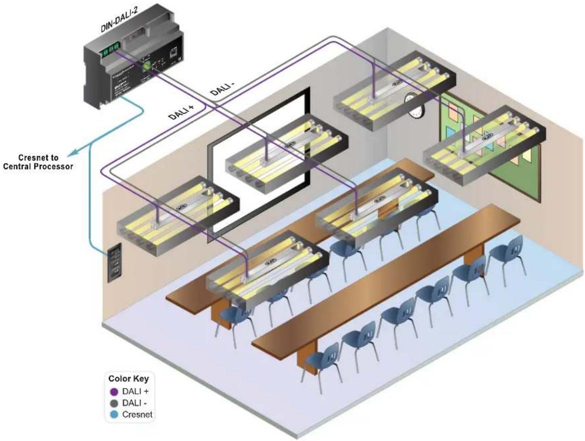
flowchart
graph TD
    A["DIN-DALI-2"] -->|DALI+| B["Cresnet to Central Processor"]
    B --> C["DALI-"]
    C --> D["Color Key: DALI +"]
    C --> E["DALI -"]
    C --> F["Cresnet"]
Glossary of Terms
Current: An electrical charge's rate of flow (conveyed in amperes).
Driver: An electrical device used in fluorescent fixtures to provide voltage, current, and waveform for operating lamps (sometimes referred to as a ballast).
Emergency lighting: Light provided for walking paths and buildings during power outages (due to bad weather or other conditions).
Fade delay: The time gap that occurs when a change is made to the light intensity level.
Fade time: The total time a dimmer takes to change lighting from one level to another level.
LED driver: An electrical device used to regulate power to an LED or a string of LEDs.
Occupancy sensor: A sensor that automatically turns lights on when a space is occupied and off when a space is unoccupied.
Photosensor: An electronic unit that can detect the presence of light.
Scene: A lighting effect attained when one or more lighting zones are adjusted to a certain intensity.
Voltage: The electrical power (expressed in volts) of the pressure provided by an electrical circuit to a light source.
Watt: A standard unit of power used by electrical devices.



- Contents
- Introduction 1
- Crestron Fusion® Software and DALI 5
- DALI Commissioning Tool 6
- Crestron DALI Related Products 8
- DIN-DALI-2 Interface 13
- DALI LED Drivers 14
- DALI Loop Wiring 16
- DALI Application Examples 17
- Glossary of Terms 21
- Introduction
- Crestron and DALI-AG Working Group
- Communicating with DALI
- DALI Requirements
- Emergency and DALI Drivers
- Crestron Fusion® Software and DALI
- DALI Commissioning Tool
- Crestron DALI Related Products
- Crestron DALI Control Systems
- DIN Enclosures
- GL-EXP Series
- Crestron DALI Accessories
- DIN-DALI-2 Interface
- DALI LED Drivers
- DALI Loop Wiring
- DALI Application Examples
- Individual Office
- Multiple Offices
- Conference Room
- Training Room
- Glossary of Terms
Brand : Crestron
Model : DIN-EN-3X18
Category : Lighting