
SW4 - Professional audio equipment Radial Engineering - Free user manual and instructions
Find the device manual for free SW4 Radial Engineering in PDF.


| Product Type | Audio Switcher / Guitar Pedal Switcher |
| Number of Channels | 4 |
| Circuit Type | Passive, True Bypass |
| Inputs/Outputs | 4 x 1/4" TRS Input, 1 x 1/4" TRS Output |
| Remote Control | 1 x 1/4" TRS for External Footswitch |
| Dimensions | 5.5" x 4.5" x 2.0" (140 x 114 x 51 mm) |
| Weight | 1.5 lbs (0.68 kg) |
| Power Requirement | None (Passive) |
| Construction | 14-gauge steel chassis |
| Finish | Durable powder coat |
| Signal-to-Noise Ratio | > 100 dB |
| Frequency Response | 20 Hz - 20 kHz (±0.1 dB) |
| Maximum Input Level | +10 dBu |
| Switching Mechanism | Mechanical latching switch |
| LED Indicators | For each channel (active channel illuminated) |
| Compatibility | Guitar, bass, line level signals |
| Included Accessories | Rubber feet, mounting screws, quick start guide |
| Cleaning Instructions | Wipe with a dry cloth; avoid solvents |
| Safety Precautions | Do not expose to moisture; use only with approved accessories |
| Repairability | No user-serviceable parts; contact Radial support |
Frequently Asked Questions - SW4 Radial Engineering
User questions about SW4 Radial Engineering
0 question about this device. Answer the ones you know or ask your own.
Ask a new question about this device
Download the instructions for your Professional audio equipment in PDF format for free! Find your manual SW4 - Radial Engineering and take your electronic device back in hand. On this page are published all the documents necessary for the use of your device. SW4 by Radial Engineering.
USER MANUAL SW4 Radial Engineering
Radial SW4 Balanced Switcher Owner's Manual
TABLE OF CONTENTS PAGE
Overview....1
Feature Set Overview....2
Features and Function Details....3
Getting Started 4
Basic A/B Switching....4
Stereo Switching Connections....5
Channel Linking....5
Mix Bus....6
Unbalanced Guitar Outputs....7
A+B Mixing (Channel-1) 7
Headphones and PFL Monitoring 8
Using the Mono Output....8
JR•2 Remotes 8
Applications 9 - 12
Specifications 13
Block Diagram....13
Warranty Back Cover
INTRODUCTION
Thank you for purchasing the Radial SW4 four-channel switcher. The SW4 is part of Radial's growing family of audio switchers designed for use in professional touring and installations where audio routing can be advantageous.
As you delve into the SW4, you will soon come to realize that although the basic design and functionality is quite simple, there are many little extras that have been added to provide maximum flexibility. This we hope will open the door to resolving challenges that may have been difficult to address in the past. Please take a few minutes to read through this manual so that you can familiarize yourself with the many features and functions. There are also a number of applications that are worth reviewing which could open doors to other creative uses.
If after reading you have questions that are not covered in the user guide, please visit the FAQ page on the web site. This is where we post the latest updates and answers from users. If you do not find what you need, feel free to send us an email at info@radialeng.com and we will do our best to reply in short order.
Now get ready to start switching audio with more speed and elegance than ever before!
Note: The Radial SW4 is solely intended for use by audio professionals. These professionals are expected to be familiar with safety issues regarding electrical systems and sound pressure levels that could cause ear damage after extended exposure. If you are not familiar with these, please contact your local electrical and health authorities as Radial has no means to ensure products like the SW4 are being used according to local rules and regulations.
SW4 OVERVIEW
Housed in a single space 19" rack enclosure, the Radial SW4 is a balanced analog audio switcher with four channels, each of which is equipped with A and B XLR inputs and a dedicated XLR output. The four individual channels are essentially straight wire connections. There are no buffers or amplifiers in the signal path that could distort or introduce artifact.
The signal flow for each channel is diagramed below. After the A and B inputs, a set of trim controls allow you to fine tune input levels. Switching the A/B inputs can be done via the front panel A/B selector or using the optional JR•2 remote. Each channel may be used independently or channels may be linked together for stereo, three-channel or four-channel switching.

flowchart
graph TD
    A["BALANCED INPUT-A"] --> B["TRIM LEVEL A"]
    C["BALANCED INPUT-B"] --> D["TRIM LEVEL B"]
    B --> E["A/B SELECT SWITCH"]
    D --> E
    E --> F["MUTE ON/OFF"]
    F --> G["ISOLATION TRANSFORMER"]
    G --> H["CHANNEL OUTPUT"]
    I["LINK SWITCH"] --> J["To next channel A/B switch"]
    K["GROUND LIFT"] --> G
    L["MIX BUS ON/OFF"] --> G
    M["STEREO OUTPUT"] --> H
    N["JR-2 REMOTE A/B SWITCH"] --> E
To eliminate hum and buzz caused by ground loops, each channel output is transformer isolated and equipped with a ground lift switch. These are rated to handle signal levels in excess of +20dB from 20Hz to 20kHz and work equally well when switching the outputs from professional mixing consoles as they do for wireless microphones and instrument level signals.
The output from each channel may be independently routed to the stereo mix bus. This equipped with balanced XLR and 14 " outputs. The mix bus allows you to create a stereo mix from any of the four channels. Channels-1 and 3 are routed to the left output while 2 and 4 are routed to the right output. A top-mounted mono-sum switch may be engaged to route all four channels to both outputs.
System monitoring is fully supported with signal present LEDs on each input and a PFL (Pre-Fader Listen) system. The PFL system enables the audio engineer to listen to the primary input-A or secondary input-B sources before switching using headphones or a powered monitor speaker.
There are many applications where the SW4 can be used. Examples include: switching backup wireless microphones or guitars on a busy stage; switching multi-channel backing tracks from a DAW workstation for a live musical performance; switching FOH mixing consoles at a music festival. Several of these are detailed later in the manual.

flowchart
graph TD
    A["Wireless Mics Primary"] --> B["DAW Workstation Primary"]
    C["DAW Workstation Primary"] --> B
    D["DAW Workstation Primary"] --> B
    E["DAW Workstation Primary"] --> B
    F["DAW Workstation Primary"] --> B
    G["DAW Workstation Primary"] --> B
    H["DAW Workstation Primary"] --> B
    I["DAW Workstation Primary"] --> B
    J["DAW Workstation Primary"] --> B
    K["DAW Workstation Primary"] --> B
    L["Mixing Console"] --> B
    style B fill:#f9f,stroke:#333,stroke-width:2px
flowchart
graph TD
    subgraph Left_Center_Right_Front_Fills
        A["FOH Mixer-1"] -->|L C R F| B["Central Interface"]
        C["FOH Mixer-2"] -->|L C R F| D["Central Interface"]
        B --> E["Drone 1"]
        B --> F["Drone 2"]
        B --> G["Drone 3"]
        B --> H["Drone 4"]
    end
    style Left_Center_Right_Fends fill:#f9f,stroke:#333
    style Left_Center_Right_Fends fill:#ccf,stroke:#333
FEATURE SET OVERVIEW

- INPUT CHANNELS (1-4): Each of the four independent channels feature A/B switching, trim level controls, LED signal indicators and PFL monitoring.
- STEREO LINKING: Channels may be used independently or linked together for stereo, tri-channel or quad switching.
- PFL MONITOR: Pre-fader listen switch allows the A or B input to be monitored via the headphone and auxiliary 1/4" mono outputs.
- BUS OUT: Volume control with on/off switch and LED indicator lets you set the level of the mix bus XLR and 1/4" outputs.
- PHONES: Headphone amplifier equipped with a level control to monitor the stereo mix bus and PFL system.
-
POWER SUPPLY: External power supply connects with a locking XLR connector for reliable power.
-
FOOT SW and LINK JACKS: The 14 " FOOT SW jack is used to connect the optional Radial JR•2 remote control. The 14 "LINK jack is used to pass the control command to more SW4s and expand the number of channels.
- BUS OUTPUTS: Stereo balanced XLR and unbalanced 1/4" outputs. Each channel can feed the bus whereby Channels-1 and 3 are routed to the left output and Channels-2 and 4 routed to the right. A top mounted mono sum switch may be engaged to route all four channels to both outputs.
- CHANNEL INPUTS: Each channel has A and B balanced inputs for connecting primary and backup source devices.
- CHANNEL OUTPUT: Each of the four channels features a balanced XLR output that is transformer isolated to prevent hum and buzz caused by ground loops.
TOP PANEL DETAILS

flowchart
graph TD
    A["CHANNEL 1"] --> B["CHANNEL 2"]
    B --> C["CHANNEL 3"]
    C --> D["CHANNEL 4"]
    D --> E["REAR PANEL BUS OUTPUT"]
    E --> F["BUS ASSIGN"]
    style A fill:#f9f,stroke:#333
    style B fill:#f9f,stroke:#333
    style C fill:#f9f,stroke:#333
    style D fill:#f9f,stroke:#333
    style E fill:#ccf,stroke:#333
    style F fill:#cff,stroke:#333
- GROUND LIFT: Disconnects the ground from the channel XLR outputs to eliminate hum and buzz caused by ground loops.
-
BUS TRIM: This 'set-n-forget' control is used to set the level of the left and right 14 " outputs. It allows the XLR and 14 " bus outputs to operate at different levels.
-
BUS GROUND LIFT: Disconnects the ground from the stereo bus XLR outputs to eliminate hum and buzz caused by ground loops.
- BUS ASSIGN: This two position switch lets you operate the mix bus in either stereo or mono.
INPUT CHANNEL DETAILS
- ON: This switch turns the channel output on. When the channel is turned on, the LED indicator illuminates. When turned off, the channel output is muted.
- BUS: This recessed switch routes the output of the channel to the stereo mix bus. Channel-1 and 3 are routed to the left output, and Channel-2 and 4 routed to the right. The LED indicator illuminates when the channel is being routed to the mix bus.
- A+B (CHANNEL-1 ONLY): This recessed switch allows both A and B inputs to be active at the same time. When engaged the LED illuminates and the A/B select switch is disabled and used to combine sources.
- TRIM A and B: These 'set-n-forget' level controls are used to match the input levels of the A and B sources for seamless audio switching.
- A/B SELECT SWITCH and LEDs: Front panel control for toggling the A and B inputs. LED indicators display which input source is active.
- SIGNAL LED: Two signal present LED indicators under each trim control illuminate when signal is detected at the A and B inputs. Used to confirm the source devices are connected and working before switching.
- PFL SWITCH: This three position switch lets you listen to either the A or B input through the headphone and auxiliary 14 " mono outputs. An LED indicator illuminates when the PFL system is active.
- LINK: This recessed switch ties the A/B switching to the next adjacent channel. Allows more than one channel to be switched at the same time.
MIX BUS AND HEADPHONE DETAILS
- BUS OUT: Controls the output level of the stereo mix bus. Features an on/off switch and LED indicator.
- MUTE INDICATOR: LED illuminates to show the SW4 is responding to the MUTE command issued from the optional Radial JR•2 footswitch or DT2 desktop remotes. When active, all outputs except the front panel phones and 14 " mono are muted.
- PFL INDICATOR: Indicates the headphones are monitoring the PFL system and one or more of the channel PFL switches is set to listen to its A or B inputs.
- PHONES: Level control and stereo 1/4" output for the headphone amplifier. Lets you monitor the mix bus or any of the eight inputs via the PFL system.
- MONO: 1/4" headphone mix output used to connect a powered monitor, guitar amplifier or electronic tuner. The phones level control is used to control the loudness.
- XLR BUS OUTPUTS: Balanced XLR jacks output a stereo or mono mix of the four input channels. Transformer isolated to prevent buzz and hum caused by ground loops.
- ¼" BUS OUTPUTS: Unbalanced ¼" jacks output a stereo or mono mix of the four input channels. Transformer isolated to prevent buzz.
REAR PANEL DETAILS
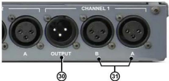
- CHANNEL OUTPUT: Transformer isolated balanced XLR outputs.
- INPUT-A and B: Balanced A and B XLR inputs for microphone, instrument or line-level signals. Wired to the AES standard with pin-1 ground, pin-2 hot (+), and pin-3 cold (-).
- XLR POWER: Locking 4-pin XLR is used to connect the external power supply to the SW4.
- FOOT SW JACK: ¼" jack used to connect the optional Radial JR•2 or JR•2DT remote controls.
- LINK JACK: 14 " jack connects to an additional SW4 and passes along the switching and mute commands. By linking multiple SW4 units you can switch eight or more A/B channels.



GETTING STARTED
As with all audio equipment, make sure signal levels are turned down or systems turned off before making connections. This will eliminate turn-on or plug-in transients from damaging more sensitive components such as tweeters and headphones. The Radial SW4 comes equipped with an external power supply with a detachable IEC cable on one end and a 4-pin XLR at the other. The power supply accepts AC power from 100 to 240 volts by simply changing the IEC cable. There is no power switch. As soon as you plug in the power supply the SW4 will spring to life and one of the many front panel LED indicators will illuminate to let you know the SW4 is ready to be used.
Before you turn up the audio, make sure the SW4 channel settings are in the start position as detailed below. You will note that many of the switches and controls are recessed. Use a small screwdriver to access the recessed switches during setup. Once you are done, you will likely leave the controls alone until the tour is over!
INPUTS-1\~4
- Channel ON switch: in (LED on)
- BUS switch: out (LED off)
- A+B switch: out (LED off; Channel-1 only)
- A/B select push button: set to A (LED-A illuminated)
- TRIM-A & TRIM-B: set fully clockwise (5 o'clock)
- PFL switch: off (LED off; middle position)
- LINK switch: out (off)
TOP PANEL SWITCHES
- GROUND LIFT 1\~4: set to lift
- Rear bus output ground: set to lift
- Rear panel trim control: set fully clockwise (5 o'clock)
- Bus assign: set to stereo
BASIC A/B SWITCHING
In order to familiarize yourself with the SW4, start by setting up the Channel-1 as a simple A/B switcher for two audio sources such as wireless microphones. Each channel is equipped with two balanced XLR female inputs labeled A/B and a balanced XLR male output. Connect your primary source to input-A and the secondary source to input-B. Connect the output of Channel-1 to your audio system. Use balanced XLR cables wired to the AES standard with pin-1 ground, pin-2 hot (+), and pin-3 cold (-).
Turn the sound system on and slowly increase the volume to a comfortable listening level. It is always best to test at a low volume as this will help reduce the chance of damage to more sensitive components should a fault be at hand.
Activate both audio sources. The input signal LEDs will flash when signal is detected to let you know that your source devices are working. Depress the front panel A/B switch to toggle to input-B. The LED will illuminate to let you know which input is active. Press the A/B switch again to toggle back to input-A.
Each channel is equipped with separate trim controls for inputs-A and B. These are used to match the level of the of the audio sources to help make switching seamless and undetectable. Start with the trim controls set to maximum (fully clockwise) and lower the trim level of the louder source to match the quieter device. Use a small slotted screwdriver to adjust the trim controls.


STEREO A/B SWITCHING
The SW4 can switch stereo audio devices like mixing consoles. A common situation is switching between a mixing console for a live band and a DJ setup in a night club. Stereo switching uses two SW4 channels where the left signals are connected to Channel-1 and the right signals to Channel-2. The outputs from the two channels are connected to the power amps and speaker arrays. To further streamline the switching process, the channels may be linked so that they toggle at the same time. This is discussed in the following section about linking channel switching.

flowchart
graph TD
    A["Primary PA Console Secondary DJ Console"] --> B["USB OUTPUT"]
    B --> C["OUTPUT"]
    B --> D["CHANNEL 1"]
    B --> E["CHANNEL 2"]
    B --> F["CHANNEL 3"]
    B --> G["CHANNEL 4"]
    B --> H["CHANNEL 5"]
    B --> I["CHANNEL 6"]
    B --> J["CHANNEL 7"]
    B --> K["CHANNEL 8"]
    B --> L["CHANNEL 9"]
    B --> M["CHANNEL 10"]
    B --> N["CHANNEL 11"]
    B --> O["CHANNEL 12"]
    B --> P["CHANNEL 13"]
    B --> Q["CHANNEL 14"]
    B --> R["CHANNEL 15"]
    B --> S["CHANNEL 16"]
    B --> T["CHANNEL 17"]
    B --> U["CHANNEL 18"]
    B --> V["CHANNEL 19"]
    B --> W["CHANNEL 20"]
    B --> X["CHANNEL 21"]
    B --> Y["CHANNEL 22"]
    B --> Z["CHANNEL 23"]
    B --> AA["CHANNEL 24"]
    B --> AB["CHANNEL 25"]
    B --> AC["CHANNEL 26"]
    B --> AD["CHANNEL 27"]
    B --> AE["CHANNEL 28"]
    B --> AF["CHANNEL 29"]
    B --> AG["CHANNEL 30"]
    B --> AH["CHANNEL 31"]
    B --> AI["CHANNEL 32"]
    B --> AJ["CHANNEL 33"]
    B --> AK["CHANNEL 34"]
    B --> AL["CHANNEL 35"]
    B --> AM["CHANNEL 36"]
    B --> AN["CHANNEL 37"]
    B --> AO["CHANNEL 38"]
    B --> AP["CHANNEL 39"]
    B --> AQ["CHANNEL 40"]
    B --> AR["CHANNEL 41"]
    B --> AS["CHANNEL 42"]
    B --> AT["CHANNEL 43"]
    B --> AU["CHANNEL 44"]
    B --> AV["CHANNEL 45"]
    B --> AW["CHANNEL 46"]
    B --> AX["CHANNEL 47"]
    B --> AY["CHANNEL 48"]
    B --> AZ["CHANNEL 49"]
    B --> BA["CHANNEL 50"]
    B --> BB["CHANNEL 51"]
    B --> BC["CHANNEL 52"]
    B --> BD["CHANNEL 53"]
    B --> BE["CHANNEL 54"]
    B --> BF["CHANNEL 55"]
    B --> BG["CHANNEL 56"]
    B --> BH["CHANNEL 57"]
    B --> BI["CHANNEL 58"]
    B --> BJ["CHANNEL 59"]
    B --> BK["CHANNEL 60"]
    B --> BL["CHANNEL 61"]
    B --> BM["CHANNEL 62"]
    B --> BN["CHANNEL 63"]
    B --> BO["CHANNEL 64"]
    B --> BP["CHANNEL 65"]
    B --> BQ["CHANNEL 66"]
    B --> BR["CHANNEL 67"]
    B --> BS["CHANNEL 68"]
    B --> BT["CHANNEL 69"]
    B --> BU["CHANNEL 70"]
    B --> BV["CHANNEL 71"]
    B --> BW["CHANNEL 72"]
    B --> BX["CHANNEL 73"]
    B --> BY["CHANNEL 74"]
    B --> BZ["CHANNEL 75"]
LINKING CHANNELS
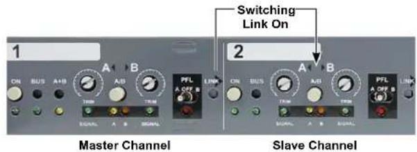
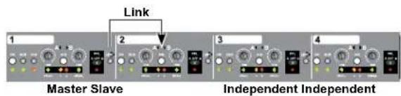
Channel linking is used when switching stereo or multi-channel audio devices. Channels one, two and three each have a LINK switch that tie the A/B switching to the next adjacent channel. The LINK switch enables you to switch two, three or all four channels by depressing the A/B select switch on the master channel or using the optional JR•2 foot switch. Push the LINK switch in to activate.
Taking this further, you can use the SW4's four channels to set up several different stereo and mono switching configurations.
Mixed Stereo/Mono Switching
3-Bus Switching Plus One Independent Channel

4-Bus Switching

Dual Stereo Switching

THE STEREO MIX BUS
Another useful feature built into the SW4 is the stereo mix bus. Each channel is equipped with a recessed BUS switch that when depressed routes the channel output to XLR and 14 " output jacks on the rear panel. An LED indicator below the BUS switch illuminates when a channel is routed to the mix bus. The odd Channels-1 and 3 are routed to the LEFT output, while the even Channels-2 and 4 are routed to the RIGHT output.
The mix bus may be operated in stereo or mono as selected by the bus OUTPUT ASSIGN switch located on the top panel. When set to mono, the program material is duplicated on both left and right outputs. Transformer isolation is used on each bus output in order to eliminate hum and buzz caused by ground loops. A 'set and forget' ground-lift switch for the XLR outputs located on the top panel further aids in reducing system noise.
The stereo mix bus is used when you mix multiple channels together. In the following example, the SW4 is used to switch between primary and backup multi-tracks. All four channels are routed to the mix bus where the signals are connected to the PA mixing console. The headphone and mono outputs are used with the PFL system to check that the tracks are playing in sync. The mix is also sent to two self powered monitors to allow the cast and crew to hear their cues from backstage. All four channels on the SW4 are linked and switch at the same time when the Channel-1 A/B selector is pressed.
Front Panel Rear Panel

Recessed BUS switch routes the channel output to the mix bus.
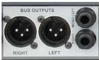
Mix bus includes balanced XLR and unbalanced 14 " outputs.
Top Panel

Bus Assign switch lets you operate the mix bus in stereo or mono.

Trim control for the mix bus 14 outs and ground lift for the XLR outputs.

flowchart
graph TD
    A["PFL Cue Speaker Headphones"] --> B["PA Mixing Console"]
    C["Primary Mult-track"] --> D["Back Stage Monitors"]
    E["Backup Mult-track"] --> F["Back Stage Monitors"]
    B --> G["PA Mixing Console"]
    D --> H["Back Stage Monitors"]
    style A fill:#f9f,stroke:#333
    style C fill:#f9f,stroke:#333
    style E fill:#f9f,stroke:#333
    style F fill:#f9f,stroke:#333
THE UNBALANCED GUITAR OUTPUTS
The mix bus is equipped with left and right 14 " high-Z guitar jacks located next to the XLR outputs. These are primarily used to feed stage amplifiers when the SW4 is used for wireless guitars and basses. The outputs are transformer isolated to eliminate noise that often gets added when connecting to high-Z guitar amps and buffered to enable long cable runs up to 15 meters (50') without appreciable noise or signal loss. This lets you position the SW4 backstage in the guitar tech's area and send long 14 " cables to the on-stage guitar amps.
The top 14 " jack is labelled MONO/LEFT while the bottom is labelled RIGHT. The RIGHT output is equipped with a switching jack that if left disconnected sums the stereo bus and routes a mono signal to the 14 " LEFT output jack. This lets you use the 14 " outputs in either stereo or mono without effecting the XLR bus outputs. A top-mounted 'set & forget' level control lets you to adjust the signal level going to the stage amps so that it sounds right to the musician. Start by testing the guitar signal using a straight cable connection from the instrument to the amp, then compare when using the wireless system and the SW4 and adjust the trim controls to suit.
EXAMPLE
The following diagram is a complex SW4 system that allows a single guitar tech to look after three guitars and a bass in a band. The tech can tune the standby instruments and monitor live instruments with the PFL system. Channel-1 is used for an acoustic guitar. The output of this channel is sent directly to the PA system and is not assigned to the mix bus. Channel-2 is used for bass and is also not assigned to the mix bus. The output connects to a Radial JDI direct box that splits the signal sending it to the bass amp and the FOH/Monitor consoles. Channels-3 and 4 are used for the rhythm and lead guitars. Both of these channels are assigned to the mix bus and output at the high-Z 14 " jacks. The mix bus is set to operate in stereo so that the lead guitar is output on the right jack and the rhythm guitar on the left jack where the guitar amplifiers connect.

flowchart
graph TD
    A["PFL Speaker HeadphonesTuner"] --> B["Guitar Tech"]
    B --> C["Rhythm Amp Lead Amp"]
    B --> D["Bass Amp"]
    B --> E["Bass DI"]
    B --> F["PA Mixing Console"]
    C --> G["Output"]
    D --> H["Output"]
    E --> I["Output"]
    F --> J["Output"]
MIXING INPUTS ON CHANNEL-1
In some situations you may want to have more than one input on at the same time. This, for example, could be to have two guitars active such as an acoustic on a stand and an electric at the ready, swung around the back, for an instant changeover. Another application could be for two wireless microphones used by a single vocalist who must switch mics backstage during a particular performance because of costume or set changes.
To address this, Channel-1 is equipped with a recessed A+B 'mix' switch that turns on both inputs. When the A+B function is engaged a resistive mixer is employed to sum the A and B inputs together. Use the trim controls to balance the signals as needed. Because the A+B function is passive, you will notice a slight reduction in level. This is easily compensated for at your mixer. Set the A+B switch to the inward position to turn both Channel-1 inputs on. Set the A+B switch to the outward position to use the Channel-1 A/B switching normally.

A+B Mix Switch On Channel-1
THE PFL AND HEADPHONES
The front panel is equipped with 14 " PHONES and MONO outputs that allow you to monitor the stereo mix bus or the individual inputs via the PFL system (Pre-Fader Listen). Each channel is equipped with a 3-position PFL (Pre-Fader Listen) switch that lets you audition the A and B inputs. Move the PFL switch to the left position to listen to input-A and to the right to listen to input-B. The center position turns the PFL system off. When all four PFL selector switches are turned off the PHONES and MONO outputs revert to monitoring the stereo mix bus.
When a PFL switch is activated, the LED indicator below the PFL switch illuminates as will the PFL indicator next to the headphone output indicating you are monitoring the PFL system. The headphone output works in stereo when monitoring the mix bus and mono when the PFL system is active. The mix bus XLR outputs on the rear panel are not affected by the PFL system and will continue uninterrupted while you use the PFL switches to monitor the individual inputs.
USING THE MONO OUTPUT
The 1/4" MONO jack is a high-Z unbalanced output for connecting a self powered monitor speaker, guitar amp or electronic tuner. The mono output can simplify setups. For instance, when using several wireless guitars, connecting the mono out to a tuner enables the guitar tech to audition and tune the standby guitar using the PFL system and quickly revert to the live channel without having to disconnect and reconnect wireless transmitters. The output level is adjusted using the headphone volume control.
REMOTE SWITCHING AND MUTE
Channel-1 can be remotely switched using the Radial JR•2 footswitch or JR•2-DT desktop remotes. These optional remotes have two selector switches, one is designated A/B and the other as MUTE. The A/B switch on the JR•2 remote works like the A/B select switch on Channel-1. When depressed it toggles the Channel-1 inputs along with any adjacent channels that are linked.
The MUTE switch is used to silence all outputs except for the headphone and mono outputs on the front panel. When depressed, the individual channel and mix bus outputs are muted and the MUTE LED on the front panel illuminates. The mute is used to turn off microphones, instruments or backing tracks when not in use. This is particularly beneficial for backing track technicians as it enables them to cue up tracks using the headphones without disturbing what may be happening on stage.
The JR•2 remote connects to the FOOT SW jack on the rear panel using a 14 " TRS cable. For larger system requirements, several SW4's may be linked together using the LINK jack. Connect the first 'master SW4' output using a 14 " TRS cable from the LINK jack to the 'slave SW4' using the FOOT SW input. Both the A/B and MUTE functions will be transmitted to all SW4 units.

JR·2 Footswitch Remote
Order No. R800 2090 00
The Radial JR•2 is a remote control equipped with two footswitches designated as A/B select and MUTE. The JR•2 connects to the device using a standard balanced audio cable with choice of 14 " TRS or XLR connections. Power is derived from the device being controlled. On-board LED indicators show the remote status. Both switches are latching type.

JR·2DT Desktop Remote
Order No: R800 2091 00
Desktop version of the JR•2 with push-button A/B and MUTE switches. It comes with both an isolation Pad for 'free placement' and a Velcro strip to attach to a desktop, work surface or flight case. An optional L bracket enables the JR•2DT to be permanently mounted.

Front panel bus and headphones controls.
NOTE: The headphone output is very loud in order to provide enough level to monitor when on stage during loud concerts. Extended exposure to high sound pressure levels can cause permanent hearing damage. As the Radial SW4 is intended for professional use, the user should be well aware of the exposure limits and safety requirements. Please consult your local health agency for details.

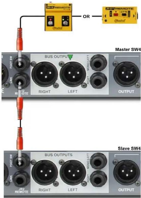
JR·2 remote and expansion link jacks

SW4 APPLICATION DIAGRAMS
Wireless Microphone Switcher:
Wireless mics can be unpredictable but the freedom of movement they offer outweigh their many liabilities. The SW4 makes it easy to manage large numbers of wireless and their backup units. The biggest advantage for the production is how fast a switch can happen because the primary and backup mics share the same snake, mixer and monitor channels. Usually the vocal wireless mics are managed by the monitor mixer on the side of the stage. Should a mic drop out, the monitor engineer has to quickly jump to the backup mics channel and then use the intercom to call up to the FOH engineer to inform them the vocalist is using the backup channel. If the mic was to go down in the middle of a song it may take some time to get the message to the FOH engineer. The SW4 streamlines this process because it does not need a second mixer channel for the backup wireless. The monitor engineer can simply toggle an SW4 channel and the change-over from one wireless to another is completely seamless.

flowchart
graph TD
    A["Switch"] --> B["Switch 1"]
    A --> C["Switch 2"]
    A --> D["Switch 3"]
    A --> E["Switch 4"]
    A --> F["Switch 5"]
    A --> G["Switch 6"]
    A --> H["Switch 7"]
    A --> I["Switch 8"]
    A --> J["Switch 9"]
    A --> K["Switch 10"]
    A --> L["Switch 11"]
    A --> M["Switch 12"]
    A --> N["Switch 13"]
    A --> O["Switch 14"]
    A --> P["Switch 15"]
    A --> Q["Switch 16"]
    A --> R["Switch 17"]
    A --> S["Switch 18"]
    A --> T["Switch 19"]
    A --> U["Switch 20"]
    A --> V["Switch 21"]
    A --> W["Switch 22"]
    A --> X["Switch 23"]
    A --> Y["Switch 24"]
    A --> Z["Switch 25"]
    A --> AA["Switch 26"]
    A --> AB["Switch 27"]
    A --> AC["Switch 28"]
    A --> AD["Switch 29"]
    A --> AE["Switch 30"]
    A --> AF["Switch 31"]
    A --> AG["Switch 32"]
    A --> AH["Switch 33"]
    A --> AI["Switch 34"]
    A --> AJ["Switch 35"]
    A --> AK["Switch 36"]
    A --> AL["Switch 37"]
    A --> AM["Switch 38"]
    A --> AN["Switch 39"]
    A --> AO["Switch 40"]
    A --> AP["Switch 41"]
    A --> AQ["Switch 42"]
    A --> AR["Switch 43"]
    A --> AS["Switch 44"]
    A --> AT["Switch 45"]
    A --> AU["Switch 46"]
    A --> AV["Switch 47"]
    A --> AW["Switch 48"]
    A --> AX["Switch 49"]
    A --> AY["Switch 50"]
    A --> AZ["Switch 51"]
    A --> BA["Switch 52"]
    A --> BB["Switch 53"]
    A --> BC["Switch 54"]
    A --> BD["Switch 55"]
    A --> BE["Switch 56"]
    A --> BF["Switch 57"]
    A --> BG["Switch 58"]
    A --> BH["Switch 59"]
    A --> BI["Switch 60"]
    A --> BJ["Switch 61"]
    A --> BK["Switch 62"]
    A --> BL["Switch 63"]
    A --> BM["Switch 64"]
    A --> BN["Switch 65"]
    A --> BO["Switch 66"]
    A --> BP["Switch 67"]
    A --> BQ["Switch 68"]
    A --> BR["Switch 69"]
    A --> BS["Switch 70"]
    A --> BT["Switch 71"]
    A --> BU["Switch 72"]
    A --> BV["Switch 73"]
    A --> BW["Switch 74"]
    A --> BX["Switch 75"]
    A --> BY["Switch 76"]
    A --> BZ["Switch 77"]
    A --> CA["Switch 78"]
    A --> CB["Switch 79"]
    A --> CC["Switch 80"]
    A --> CD["Switch 81"]
    A --> CE["Switch 82"]
    A --> CF["Switch 83"]
    A --> CG["Switch 84"]
    A --> CH["Switch 85"]
    A --> CI["Switch 86"]
    A --> CJ["Switch 87"]
    A --> CK["Switch 88"]
    A --> CL["Switch 89"]
    A --> CM["Switch 90"]
    A --> CN["Switch 91"]
    A --> CO["Switch 92"]
    A --> CP["Switch 93"]
    A --> CQ["Switch 94"]
    A --> CR["Switch 95"]
    A --> CS["Switch 96"]
    A --> CT["Switch 97"]
    A --> CU["Switch 98"]
    A --> CV["Switch 99"]
    A --> CW["Switch 100"]

    subgraph Wireless-1
        direction TB
        W1["Wireless-1"]
        W2["Wireless-1BU"]
        W3["Wireless-1"]
        W4["Wireless-1BU"]
        W5["Wireless-1"]
        W6["Wireless-1"]
        W7["Wireless-1"]
        W8["Wireless-1"]
        W9["Wireless-1"]
        W10["Wireless-1"]
        W11["Wireless-1"]
        W12["Wireless-1"]
        W13["Wireless-1"]
        W14["Wireless-1"]
        W15["Wireless-1"]
        W16["Wireless-1"]
        W17["Wireless-1"]
        W18["Wireless-1"]
        W19["Wireless-1"]
        W20["Wireless-1"]
        W21["Wireless-1"]
        W22["Wireless-1"]
        W23["Wireless-1"]
        W24["Wireless-1"]
        W25["Wireless-1"]
        W26["Wireless-1"]
        W27["Wireless-1"]
        W28["Wireless-1"]
        W29["Wireless-1"]
        W30["Wireless-1"]
        W31["Wireless-1"]
        W32["Wireless-1"]
        W33["Wireless-1"]
        W34["Wireless-1"]
        W35["Wireless-1"]
        W36["Wireless-1"]
        W37["Wireless-1"]
        W38["Wireless-1"]
        W39["Wireless-1"]
        W40["Wireless-1"]
        W41["Wireless-1"]
        W42["Wireless-1"]
        W43["Wireless-1"]
        W44["Wireless-1"]
        W45["Wireless-1"]
        W46["Wireless-1"]
        W47["Wireless-1"]
        W48["Wireless-1"]
        W49["Wireless-1"]
        W50["Wireless-1"]
        W51["Wireless-1"]
        W52["Wireless-1"]
        W53["Wireless-1"]
        W54["Wireless-1"]
        W55["Wireless-1"]
        W56["Wireless-1"]
        W57["Wireless-1"]
        W58["Wireless-1"]
        W59["Wireless-1"]
        W60["Wireless-1"]
        W61["Wireless-1"]
        W62["Wireless-1"]
        W63["Wireless-1"]
        W64["Wireless-1"]
        W65["Wireless-1"]
        W66["Wireless-1"]
        W67["Wireless-1"]
        W68["Wireless-1"]
        W69["Wireless-1"]
        W70[GNDI/DAI/DAI/DAI/DAI/DAI/DAI/DAI/DAI/DAI/DAI/DAI/DAI/DAI/DAI/DAI/DAI/DAI/DAI/DAI/DAI/DAI/DAI/DAI/DAI/DAI/DAI/DAI/DAI/DAI/DAI/DAI/DAI/DAI/DAi / DAI / DAI / DAI / DAI / DAI / DAI / DAI / DAI / DAI / DAI / DAI / DAI / DAI / DAI / DAI / DAI / DAI / DAI / DAI / DAI / DAI / DAI / DAI / DAI / DAI / DAI / DAI / DAI / DAI / DAI / DAI / DAI / DAI / DAI, DAI / DAI / DAI / DAI / DAI / DAI / DAI / DAI / DAI / DAI / DAI / DAI / DAI / DAI / DAI / DAI / DAI / DAI / DAI / DAI / DAI / DAI / DAI / DAI / DAI / DAI / DAI / DAI / DAI / DAI / DAI / DAI / DAI / Da |
FOH Mixing Console Switcher:
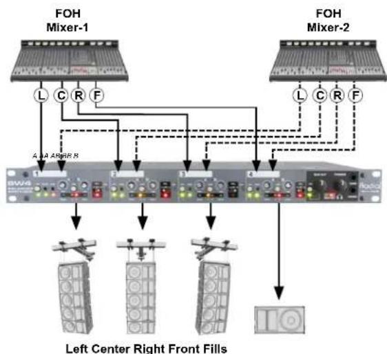
This setup details a multi-channel system where the SW4 switches between two FOH mixing consoles. This type of setup is common where one console is dedicated to the opening act while the second is for the headlining performer. The SW4 gives you an easy way to instantly switch consoles even when connecting to large LCR sound reinforcement systems. Connections are straight forward. The SW4 is placed in between the mixing consoles and the speaker processing/power amps. The balanced LCR bus outputs from each console pass through Channels-1 thru 3. A submaster or auxiliary send from each console is often used to drive front fill speakers or subs. All of the SW4 channels are linked and switching from one console to another is done using a JR·2DT remote control. The bright LED indicators on the remote constantly alert the engineers as to which console is live. As an option you could employ the mix bus to connect an FM transmitter that broadcasts a mono mix to far flung areas of the festival like the beer garden and food concessions.

flowchart
graph TD
    A["FOH Mixer-1"] --> B["Mixer-1 LEFT"]
    A --> C["Mixer-1 CENTER"]
    A --> D["Mixer-1 RIGHT"]
    A --> E["Mixer-1 FILLS"]
    F["FOH Mixer-2"] --> G["Mixer-2 LEFT"]
    F --> H["Mixer-2 CENTER"]
    F --> I["Mixer-2 RIGHT"]
    F --> J["Mixer-2 FILLS"]
    K["JR-2DT"] --> L["FM Transmitter"]
    K --> M["FL Listeners"]
    K --> N["Front Fill"]
    K --> O["Left Array"]
    K --> P["Center Cluster"]
    K --> Q["Right Array"]
Effects Switcher:
Where effects out-number aux sends or returns on a live FOH console, the SW4 can help by being able to switch between effects without repatching or taking up additional channels. This is very helpful especially when using vintage gear where changing effects on a specific processor cannot be done via midi control. The effects inputs are connected together with 'Y' cables so one aux line out from the console will connect two effects inputs. This enables the engineer to set levels on both effects at the same time. The outputs can then be connected to input A and B on the SW4. The output of the channel on the SW4 can now be connected to one aux or effect return on the console. With the SW4 PFL bus and headphones, you can monitor each effect without switching or routing signal back into the console and PFL at the console. This is very handy as a 'preview' monitor before a switch is made. Using the JR•2 foot switch input, a change can be automated with a contact closure from a show control system.
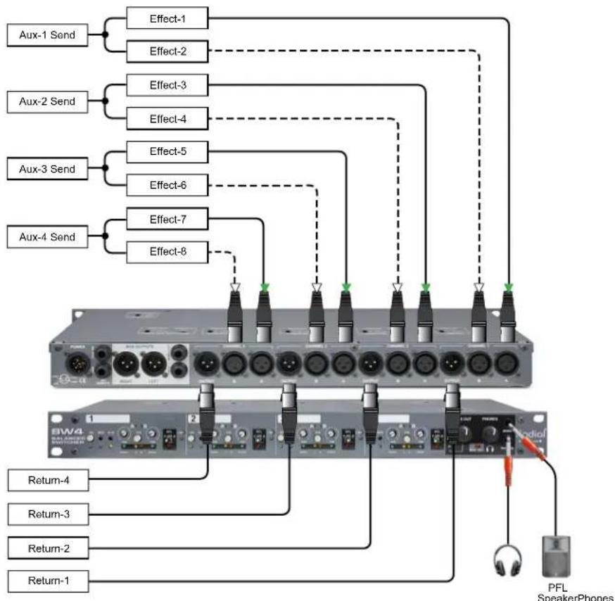
flowchart
graph TD
    A["Aux-1 Send"] --> B["Effect-1"]
    A --> C["Effect-2"]
    D["Aux-2 Send"] --> E["Effect-3"]
    D --> F["Effect-4"]
    G["Aux-3 Send"] --> H["Effect-5"]
    G --> I["Effect-6"]
    J["Aux-4 Send"] --> K["Effect-7"]
    J --> L["Effect-8"]
    M["BW4 Audio"] --> N["Return-4"]
    M --> O["Return-3"]
    M --> P["Return-2"]
    M --> Q["Return-1"]
    R["PFL Speaker Phones"] --> S["Switch"]
    style R stroke:#ff0000,stroke-width:2px
    style S stroke:#ff0000,stroke-width:2px
Backing Tracks Switcher:
This application shows the SW4 switching between a primary and backup DAW multi-track to provide backing tracks for a live performance. Should the primary multi-track stop playing, the technician can switch the SW4 to the backup DAW. To handle eight tracks of playback a second SW4 unit is slaved by connecting the JR•2 link 'out' jack from the master SW4 to the JR•2 remote 'in' jack. This allows the master unit to pass switching and mute commands to the slave. Both SW4 units are set up so that all channels switch at the same time and the technician can trigger the switching using the JR•2DT or the A/B switch on channel-1. To facilitate monitoring and cueing of the backing tracks, the mono output from each SW4 is connected to additional mixing console channels and the PFL system on the SW4's is set to monitor the backup multi-track. The technician can then use their mixing console to listen to the SW4's PFL system or the DAW systems to ensure playback is in sync.
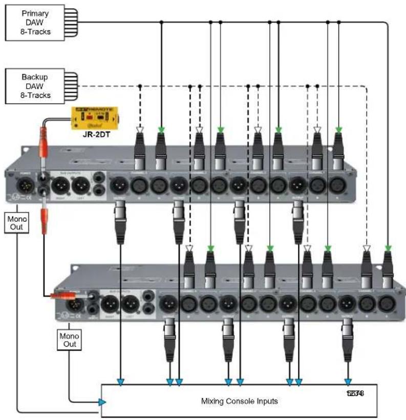
flowchart
graph TD
    A["Primary DAW 8-Tracks"] --> B["JR-2DT"]
    C["Backup DAW 8-Tracks"] --> B
    D["Mono Out"] --> B
    E["Mono Out"] --> F["Mixing Console Inputs"]
    B --> G["Output 10374"]
    style B fill:#f9f,stroke:#333
    style F fill:#bbf,stroke:#333
Stereo Background Music Switcher:
When setting up BGM (back ground music) sources, many different source players or types of players may be used. With this usually comes the need to select trim for several devices to allow easy switching between systems or automate switching between units on a set schedule. The SW4 can switch between mono signals on each individual channel or switch between stereo pairs to a common bus. Using the contact closure foot-switch remote input, this function can be controlled globally for automated switching. In addition, the PFL switch and PFL bus allow you to monitor the signal from a BGM source before it is switched live.
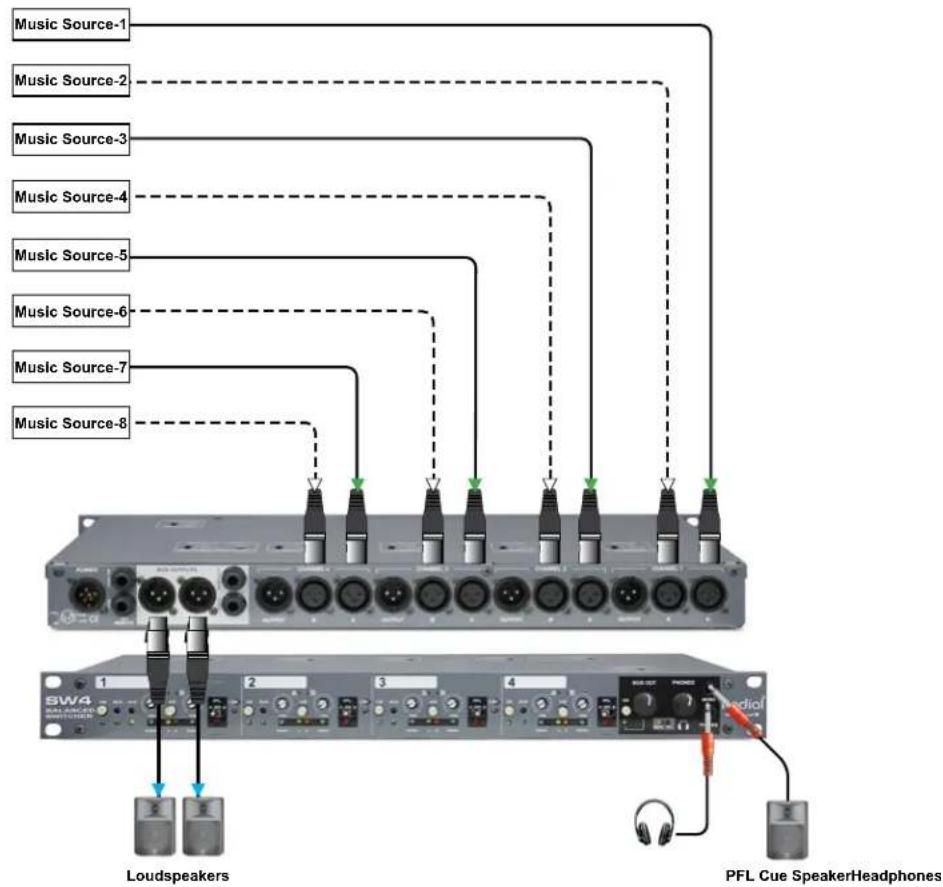
flowchart
graph TD
    A["Music Source-1"] --> B["Switch"]
    C["Music Source-2"] --> B
    D["Music Source-3"] --> B
    E["Music Source-4"] --> B
    F["Music Source-5"] --> B
    G["Music Source-6"] --> B
    H["Music Source-7"] --> B
    I["Music Source-8"] --> B
    B --> J["Loudspeakers"]
    B --> K["PFL Cue SpeakerHeadphones"]
PFL Monitor:
When using equipment such as dynamics for output control for live stage mixes or in-ear mixes, the ability to monitor the signal in real time before or after a processor can be very helpful to set levels and set up release slopes or other aspects of the dynamics. This is also handy for any processing where pre and post monitoring may be required.
Connecting the signal to a processor from a mix output, use a Y connector and send one signal to the input of the processor and one signal to SW4 input A. Another Y connector will connect from the output of the processor to the signal path to the mix amp or send path and the other side of the Y connector will patch to the SW4 input B. Using the PFL switch on front panel, the monitor signal can be switched between SW4 input A and B without interrupting the original signal path or using extra console inputs for PFL or monitoring.

flowchart
graph TD
    A["InEar Mix-1"] --> B["Comp/Limit-1"]
    C["InEar Mix-2"] --> D["Comp/Limit-2"]
    E["InEar Mix-3"] --> F["Comp/Limit-3"]
    G["InEar Mix-4"] --> H["Comp/Limit-4"]
    B --> I["InEar Mix-1 Transmitter"]
    D --> J["InEar Mix-2 Transmitter"]
    F --> K["InEar Mix-3 Transmitter"]
    H --> L["InEar Mix-4 Transmitter"]
    I --> M["PFL Cue Speaker Headphone"]
    J --> M
    K --> M
    L --> M
    M --> N["SW4 Radio"]
Manage All Guitars In A Band:
The SW4 has the facilities to allow a single guitar tech to manage all the instruments in a band and their backup instruments too. In this application each player uses a main guitar and a backup, each with it's own wireless system. The outputs from the wireless receivers connect to the SW4 channel inputs. The main instrument connects to input-A and the backup to input-B allowing instant change-overs for each player by toggling the A/B inputs. The guitar tech can use the PFL system to tune the instruments on standby and listen to the live instruments. Channel-1 is allocated to the lead singers acoustic guitar and the channel output connects directly to the PA mixing console. Channel-2 is dedicated to the bass player's instruments. This channel output also connects to the PA mixing consoles but uses a Radial JDI direct box to split the signal and send it to the bass player's amp. It's important to note Channels-1 and 2 are not assigned to the mix bus. Channels-3 and 4 are used for the rhythm and lead guitars and these channels are assigned to the mix bus. This allows the guitar connected to Channel-3 to be routed to the right output jack and the the guitar connected to Channel-4 routed to the left output jack. Because these outputs are buffered, the guitar tech can use long cables up to 50' to connect the amps allowing him to position the SW4 backstage in the guitar tech area. If that sounds like a lot going on, it is! The SW4 puts all the control in one place allowing a single tech to manage it all.

flowchart
graph TD
    A["ACoustic WL"] --> B["Bass WL"]
    C["Acoustic Backup"] --> D["Bass Backup"]
    E["Rhythm Guitar"] --> F["Rhythm Backup"]
    G["Lead Guitar"] --> H["Lead Backup"]
    I["Lead Guitar"] --> J["Lead Backup"]
    K["Bass"] --> L["JDI DI"]
    M["Accoustic"] --> N["Mixing Console Inputs"]
    O["Chips"] --> P["Tuner"]
    Q["Radio"] --> R["Switch"]
    S["Switch"] --> T["Switch"]
    U["Switch"] --> V["Switch"]
    W["Switch"] --> X["Switch"]
    Y["Switch"] --> Z["Switch"]
Guitar Hero Setup:
Taking the guitar application to the next level, the SW4 is the perfect device to manage a whole bank of guitars for your local guitar hero. These 'hired guns' of the live concert circuit are known for their ability to quickly change instruments, styles and sounds to cover a huge sonic range from rock to country to jazz. These players can't do their jobs well without an experienced guitar tech backstage keeping all their instruments tuned and ready to go according to the set list. The system begins with the player's acoustic guitar and backup connected to Channel-1. The output of the channel feeds the PA mixing console and a Radial JDI direct box is used to split the signal to an on-stage acoustic guitar amp. Channel-1 is not assigned to the mix bus but the guitar tech can use the PFL system to monitor the live instrument and tune the standby guitar. Channels-2, 3 and 4 are used for the player's three electric guitars, a Stratocaster, a Les Paul and a hollow body Gretch guitar. These channels are assigned to the mix bus and the 14 " high-Z outputs are used to connect the player's amp. Because the Strat and Gretsch are connected to even number channels they are routed to the left jack and connect to a Fender amplifier that makes the guitars sound best. The Les Paul is connected to an odd channel so it is the only guitar routed to the right output and Marshall amp.

flowchart
graph TD
    A["Acoustic WL"] --> B["Stratocaster"]
    C["Acoustic Backup"] --> B
    D["Gretsch Guitar"] --> B
    E["Gretsch Backup"] --> B
    B --> F["Strat Backup"]
    B --> G["LP Backup"]
    B --> H["Les Paul"]
    B --> I["BW4"]
    B --> J["Fender Guitar Amp"]
    B --> K["Marshall Guitar Amp"]
    B --> L["Acoustic Guitar Amp"]
    B --> M["JDI DI"]
    M --> N["Mixing Console Inputs"]
    M --> O["Phones"]
    M --> P["Tuner"]
SW4 SPECIFICATIONS\*
Audio circuit type: Passive transformer coupled with relay switching
Number of channels: 4 x AB select
Frequency response: 10Hz to 40Khz
Dynamic range: 136dB
Total harmonic distortion: 0.002%
Phase deviation: ....<3° at all frequencies
Inermodulation distortion: 0.01%
Input impedance: Load impedance in parallel with 10K
Maximum input: ....+26dBu channel to channel
Maximum input: ....+17dBu channel to bus
Channel to channel gain: -0.26dB with 10k Ohm load -2.3dB with 600 Ohm load
Channel to bus gain: ....+ 8dB with 10k Ohm load
Channel output impedance: 160 Ohms
Bus output impedance: 500 Ohms
Transformer:..... Eclipse ET-LD2 line output
Input pad: Variable trim control
XLR configuration: ......AES standard pin-1 ground, pin-2 (+), pin-3 (-)
Input connectors: ....XLR female
Output connectors: ....XLR male, 1/4" guitar
Power: External 100V to 240V AC
Size: (L x W x D)....1 rack unit; 19" x 6" x 1.75" (48 x 15.2 x 1.7cm)
Shipping Size: (L x W x D)....22" x 10" x 4.5" (55.9 x 25.4 x 11.4cm)
Conditions: For use in dry locations only between 5°C and 40°C
Warranty: Radial 3-year, transferable
*Specifications are subject to change without notice.
SW4 BLOCK DIAGRAM
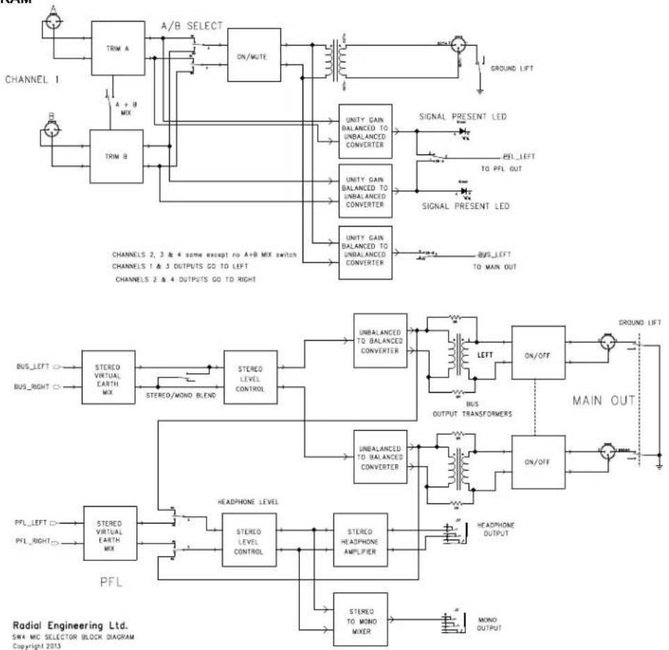
RADIAL ENGINEERING LTD.
3 YEAR TRANSFERABLE WARRANTY
RADIAL ENGINEERING LTD. ("Radial") warrants this product to be free from defects in material and workmanship and will remedy any such defects free of charge according to the terms of this warranty. Radial will repair or replace (at its option) any defective component(s) of this product (excluding finish and wear and tear on components under normal use) for a period of three (3) years from the original date of purchase. In the event that a particular product is no longer available, Radial reserves the right to replace the product with a similar product of equal or greater value. To make a request or claim under this limited warranty, the product must be returned prepaid in the original shipping container (or equivalent) to Radial or to an authorized Radial repair center and you must assume the risk of loss or damage. A copy of the original invoice showing date of purchase and the dealer name must accompany any request for work to be performed under this limited and transferable warranty. This limited warranty shall not apply if the product has been damaged due to abuse, misuse, misapplication, accident or as a result of service or modification by any other than an authorized Radial repair center.
THERE ARE NO EXPRESSED WARRANTIES OTHER THAN THOSE ON THE FACE HEREOF AND DESCRIBED ABOVE. NO WARRANTIES WHETHER EXPRESSED OR IMPLIED, INCLUDING BUT NOT LIMITED TO, ANY IMPLIED WARRANTIES OF MERCHANTABILITY OR FITNESS FOR A PARTICULAR PURPOSE SHALL EXTEND BEYOND THE RESPECTIVE WARRANTY PERIOD DESCRIBED ABOVE OF THREE YEARS. RADIAL SHALL NOT BE RESPONSIBLE OR LIABLE FOR ANY SPECIAL, INCIDENTAL OR CONSEQUENTIAL DAMAGES OR LOSS ARISING FROM THE USE OF THIS PRODUCT. THIS WARRANTY GIVES YOU SPECIFIC LEGAL RIGHTS, AND YOU MAY ALSO HAVE OTHER RIGHTS, WHICH MAY VARY DEPENDING ON WHERE YOU LIVE AND WHERE THE PRODUCT WAS PURCHASED.


- Radial SW4 Balanced Switcher Owner's Manual
- TABLE OF CONTENTS PAGE
- INTRODUCTION
- SW4 OVERVIEW
- FEATURE SET OVERVIEW
- TOP PANEL DETAILS
- INPUT CHANNEL DETAILS
- MIX BUS AND HEADPHONE DETAILS
- REAR PANEL DETAILS
- GETTING STARTED
- INPUTS-1\~4
- TOP PANEL SWITCHES
- BASIC A/B SWITCHING
- STEREO A/B SWITCHING
- LINKING CHANNELS
- THE STEREO MIX BUS
- THE UNBALANCED GUITAR OUTPUTS
- EXAMPLE
- MIXING INPUTS ON CHANNEL-1
- THE PFL AND HEADPHONES
- USING THE MONO OUTPUT
- REMOTE SWITCHING AND MUTE
- JR·2 Footswitch Remote
- JR·2DT Desktop Remote
- SW4 APPLICATION DIAGRAMS
- Wireless Microphone Switcher:
- FOH Mixing Console Switcher:
- Effects Switcher:
- Backing Tracks Switcher:
- Stereo Background Music Switcher:
- PFL Monitor:
- Manage All Guitars In A Band:
- Guitar Hero Setup:
- SW4 SPECIFICATIONS\*
- RADIAL ENGINEERING LTD.
- YEAR TRANSFERABLE WARRANTY
Brand : Radial Engineering
Model : SW4
Category : Professional audio equipment