
mPress - Professional audio equipment Radial Engineering - Free user manual and instructions
Find the device manual for free mPress Radial Engineering in PDF.


| Product Type | Modular Press Box / Command Center |
| Dimensions | 19" x 7.25" x 1.75" (482.6mm x 184.15mm x 44.5mm) |
| Weight | 6.25 lb (2.83 kg) |
| Power Supply | ±15V / +5V custom power supply with locking XLR connector |
| Chassis Material | 14 gauge steel with durable powder coat finish |
| Microphone Inputs | 2 XLR (front and rear parallel) with 48V phantom power, +51dB gain |
| Line Inputs | Rear XLR switchable mic/line, 0dB gain |
| Program Inputs | 3.5mm, RCA, 1/4" TRS (parallel), max gain +19dB |
| Gallery Outputs | 8 transformer-isolated XLR, switchable high/low level |
| Main Outputs | Left/Right XLR, clip level +24dBu/+17dBu |
| Headphone Output | 1/4" TRS, high current for 8-400Ω headphones |
| High-Pass Filter | 100Hz, 12dB/octave |
| Limiter | Adjustable threshold (-10dBu to +5dBu) and release, ratio >20:1 |
| Test Tone | 1kHz signal generator for calibrating recorders |
| Frequency Response | 20Hz to >20kHz (+0/-1.5dB) |
| Total Harmonic Distortion | <0.001% @ +4dB |
| Dynamic Range | >112dB |
| Exo-Pod Compatibility | Up to 8 Exo-Pods (star or series), total 448 outputs |
| Warranty | 3 years transferable |
| Safety & Compliance | High SPL warning, California Prop 65 compliant |
Frequently Asked Questions - mPress Radial Engineering
User questions about mPress Radial Engineering
0 question about this device. Answer the ones you know or ask your own.
Ask a new question about this device
Download the instructions for your Professional audio equipment in PDF format for free! Find your manual mPress - Radial Engineering and take your electronic device back in hand. On this page are published all the documents necessary for the use of your device. mPress by Radial Engineering.
USER MANUAL mPress Radial Engineering
OWNER'S MANUAL
Radial mPress Owner's Manual
Modular Press Box
Table of Contents
Overview....2
Features 3-4
Making Connections ....5
Optimizing Performance 6
Adding Music Playback 7
Using the mPress 8-9
Specifications and Block Diagram ....10
Warranty Back Cover
INTRODUCTION
Thank you for choosing the Radial mPress. We believe it is one of the most forward thinking press boxes made today and are confident that you will find it to be both feature rich and intuitive.
As with any new product, it is important that you take a few minutes to read the manual. Inside, you will find details on how to get the most out of the mPress along with safety tips that can prevent damage due to misuse. If afterwards, you find yourself wondering about something or feel that details may be missing, please visit the mPress FAQ page on the Radial website. This is where we post questions from users and helpful updates. If you still find yourself in need of answers, feel free to drop an email to info@radialeng.com and we will do our very best to answer in short order.
Now get ready to broadcast that message with more authority than ever!
OVERVIEW
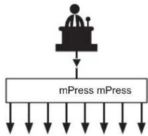
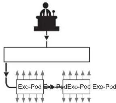
The Radial mPress is a modular press box and command center that can distribute audio to up to eight gallery recorders on its own, or be combined with multiple Radial Exo-Pod™ modules to create a larger distribution network. The mPress (active) and Exo-Pod (passive) can be connected in a star configuration where each output feeds a single Exo-Pod, a series configuration where up to four Exo-Pods can be daisy-chained from a single mPress gallery output, or any combination of the two.
Simple 8 Out
flowchart
graph TD
    A["User"] --> B["mPress"]
    B --> C["mPress"]
    C --> D["Output"]
    style A fill:#f9f,stroke:#333
    style B fill:#ccf,stroke:#333
    style C fill:#cfc,stroke:#333
Star Configuration Series Configuration

flowchart
graph TD
    A["User"] --> B["mPress"]
    B --> C["Block 1"]
    B --> D["Block 2"]
    C --> E["Output"]
    D --> F["Output"]
flowchart
graph TD
    A["User"] --> B["Server"]
    B --> C["Exo-Pod"]
    B --> D["Exo-Ped"]
    B --> E["Exo-Pod"]
    C --> F["Data Flow"]
    D --> G["Data Flow"]
    E --> H["Data Flow"]
The mPress features two microphone preamplifi ers with available 48V phantom power. XLR inputs are paralleled on the front and rear of the unit for convenience. A limiter with adjustable threshold and release controls can be engaged after the mic inputs to reduce the possibility of overloading recorder inputs. The rear XLR inputs can also be set to line level to distribute the outputs of a mixing console or other line level source.
Program material inputs (3.5mm, RCA & 1/4") are provided with a dedicated level control for the outputs of a mixing console or a music playback device. Left and right MAIN outputs allow for connection to an amplifier or powered speakers and a headphone output allows for easy monitoring.
To feed the press gallery, you can use any or all of the mPress outputs as needed. Each gallery output may be set to a low level for direct connection to a microphone input on a press recorder or PA system, or to a high level to drive Exo-Pods. Each optional Exo-Pod is equipped with 10 XLR and four 3.5mm outputs. A trim control is provided on the Exo-Pod to reduce the level from the mPress, making it suitable for connection for a variety of mic or line level devices.

FRONT PANEL FEATURES

REAR PANEL FEATURES

MAKING CONNECTIONS
Before making connections, ensure all level controls are turned down to zero (fully counter-clockwise), all switches are set in the out position and PA system speakers turned off. This prevents power turn-on transients from damaging more sensitive components such as tweeters. Plug the mPress power supply in. There is no power switch. Once connected, the mPress will spring to life. To verify power is being received, depress the MIC-1 ON switch to illuminate the LED.

Connect your first microphone to the MIC-1 input. You can use the front panel XLR or the one on the rear panel. When the rear XLR inputs are set for mic level (recessed MIC/LINE switch in the OUT position) do not use the front and rear XLR inputs simultaneously; they are wired in parallel for convenience. If phantom power is needed, activate the 48V power switch using a small screwdriver. This switch is recessed to avoid accidentally engaging or disengaging phantom power. Connect a pair of headphones to the mPress and set the headphone level control half-way (12 o'clock) to start. Slowly increase the MIC-1 input level until you see the input meter LED illuminate. Test the level for maximum input by speaking loudly until the RED LED illuminates. Then, back down the level for extra headroom. Adjust the headphone level as you go along to suit.
MIC-2 input can be used independently on a second source in a conference or town-hall meeting arrangement. In this case, connect using the same method as outlined above. When both mic inputs are engaged, they are summed after the limiter section to a mono output that will be present at each of the GALLERY OUTPUTS, the MAIN OUTPUTS, and in the HEADPHONES.
Once your mic levels are set, engage the MAIN OUT ON switch to activate the sends to the PA system and slowly raise the MAIN OUT LEVEL control until the desired output is achieved.
Rear MIC/LINE XLR Inputs
The rear XLR inputs on the mPress can be configured for MIC or LINE level operation, allowing you to use them with microphones or the outputs of a mixing console. When the recessed MIC/LINE switch is set to the 'OUT' position, these inputs will be wired in parallel with the front MIC-1 and MIC-2 inputs. When the MIC/LINE switch is set to 'IN' for line level, these inputs bypass the mic pre's and directly feed the GALLERY outputs and the MAIN outputs.
Locking XLR power supply included.

Test the microphone level with headphones before sending the signal to the mains.

Headphone Safety Warning Caution: Very Loud Amplifier See back page for details

OPTIMIZING PERFORMANCE
There are two built-in functions that can help optimize the performance of your microphones on stage: a high-pass filter and a limiter.
High-Pass Filter
A high-pass filter (HPF) is used to reduce low frequency content coming from the microphone before it is amplified. The HPF performs two very important functions. First, it gently rolls off the bottom end to clean up the signal and reduce bass resonance. This not only improves intelligibility, but also helps eliminate feedback. It can also reduce transmission noise from the podium entering the mic.
Second; reducing the bottom end also helps reduce the microphone's proximity effect. The proximity effect is caused by the speaker being too close to the microphone which, in turn, over-accentuates bass frequencies in the voice. Rolling off the bottom end solves the problem!


line
| Hz | C_B | | ------ | ------ | | 20.50 | -12.0 | | 100.00 | -8.0 | | 200.50 | -5.0 | | 300.00 | -3.0 | | 400.00 | -2.0 | | 500.00 | -1.0 | | 600.00 | -0.5 | | 700.00 | -0.2 | | 800.00 | -0.1 | | 900.00 | -0.05 | | 1000.00| -0.02 | | 1100.00| -0.01 | | 1200.00| -0.01 | | 1300.00| -0.01 | | 1400.00| -0.01 | | 1500.00| -0.01 | | 1600.00| -0.01 | | 1700.00| -0.01 | | 1800.00| -0.01 | | 1900.00| -0.01 | | 2000.00| -0.01 |Limiter
When confronted with an over-zealous orator, a clear microphone signal can quickly turn into distortion if not kept in check. But even the most experienced audio engineer cannot always prevent loud peaks from causing clipping and distortion. The mPress is equipped with a limiter to address this occurrence. It is important that you practice using the limiter on the mPress as the effect can be a bit tricky to set up at first.
There are two controls on the limiter. The first is the THRESHOLD. This sets the level at which the limiter starts to kick in and compress the signal, preventing distortion when the speaker gets too loud. Start with the THRESHOLD turned to its highest setting (fully clockwise), so that only the loudest peaks are affected. Slowly turn the THRESHOLD counter-clockwise until you hear it compress the signal. When this is audible, you are likely applying too much compression. Turn the THRESHOLD back up a couple of notches and then try yelling into the mic to ensure it keeps the level from distorting.
The RELEASE control is used to determine how quickly the limiter is 'reset' after being triggered. When set too FAST, it can cause audible pumping effects and sound unnatural. When set too SLOW, it can totally eliminate the dynamics, which is also undesirable. Start by setting the RELEASE to the middle 12 o'clock position and test it by listening as you rotate it one way, then the other. In most cases, somewhere around halfway works best.
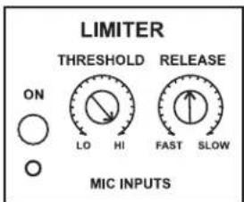
Start with the THRESHOLD fully clockwise and roll back until loud peaks no longer distort the mic pre.


In most cases leaving the RELEASE in the middle position will work best.
ADDING STEREO FEEDS FROM A MUSIC PLAYBACK DEVICE
The PROGRAM section of the mPress is equipped with a number of unbalanced line level inputs for connecting and distributing additional audio sources. You can use these inputs to connect a device for music playback to feed background music through powered loudspeakers while the audience waits.
On the front panel there are 3.5mm and RCA program inputs, while the back panel has 14 " and RCA inputs. Only one set of inputs should be used as these are all parallel connections. When the PROGRAM ON switch is depressed, these inputs are activated and sent to the GALLERY OUTPUTS, MAIN OUTPUTS and the HEADPHONES. When using powered loudspeakers, ensure that your MAIN OUT is turned on and set to an appropriate level before turning up the PROGRAM LEVEL.
CONNECTING THE GALLERY OUTPUTS
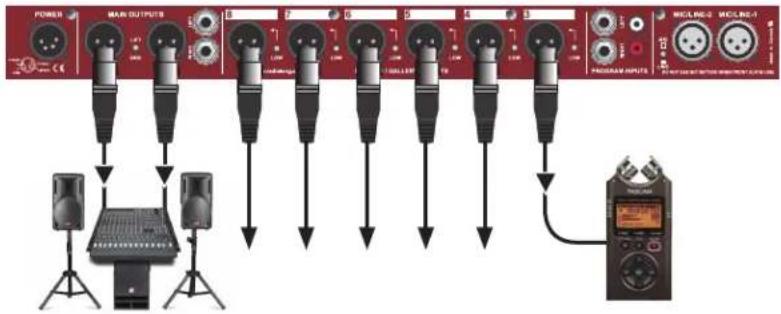
The mPress is equipped with 8 dual level transformer-isolated XLR outputs to distribute your signal to a number of recording devices without any loss in sonic clarity. Each of these outputs is a mono sum of the engaged MIC/LINE INPUTS 1 and 2, along with any active PROGRAM inputs. The first two GALLERY OUTPUTS are on the front of the mPress for convenience, while the remaining six can be found on the rear panel. Recessed switches next to each output allow the user to set the signal levels to HIGH or LOW, allowing a variety of line or mic level devices to be connected.
When connecting a mic level device, push IN the recessed switch to set to LOW output. When connecting a line level recorder or an Exo-Pod module, disengage the recessed switch for HIGH output.
TEST TONE
The mPress also features a 1kHz signal generator that sends a test tone to each of the GALLERY OUTPUTS. This allows each recording device to be simultaneously calibrated with the mPress for optimal recording level. Push IN the TEST switch to activate the test tone.


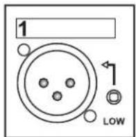

If using a line level device, disengage the recessed switch to set for HIGH output.

If using a mic level device, push IN the recessed switch to set for LOW output.

In this setup, you are using the mPress to feed up to eight recording devices in a press gallery. Ensure that the recessed switches on the GALLERY OUTPUTS are set correctly for each device (LOW for mic level recorders, HIGH for line level devices). Once connected activate the 1kHz test tone so that each recorder can be calibrated to the output of the mPress. Now test using the microphone to ensure that the signal is clean.
flowchart
graph TD
    A["Power"] --> B["MAK OUTPUTS"]
    B --> C["DAIR"]
    C --> D["DAIR"]
    D --> E["DAIR"]
    E --> F["DAIR"]
    F --> G["DAIR"]
    G --> H["DAIR"]
    H --> I["DAIR"]
    I --> J["DAIR"]
    J --> K["DAIR"]
    K --> L["DAIR"]
    L --> M["DAIR"]
    M --> N["DAIR"]
    N --> O["DAIR"]
    O --> P["DAIR"]
    P --> Q["DAIR"]
    Q --> R["DAIR"]
    R --> S["DAIR"]
    S --> T["DAIR"]
    T --> U["DAIR"]
    U --> V["DAIR"]
    V --> W["DAIR"]
    W --> X["DAIR"]
    X --> Y["DAIR"]
    Y --> Z["DAIR"]
Distributing more than two mic signals
When you have a panel of speakers, you can use the mPress to distribute the outputs of a mixing console via the rear MIC/LINE inputs. In this configuration, you can also connect backup microphones through the mPress MIC INPUTS which will keep running even if the mixing console goes down or loses power.

flowchart
graph TD
    A["User at podium"] --> B["Line Level Selection"]
    C["User at podium"] --> B
    D["mPress Front"] --> E["Line Level Selection"]
    F["mPress Rear"] --> G["Line Level Selection"]
    H["Backup mic into the mPress"] --> B
    I["+4dB"] --> B
Exo-Pod Modules
The optional Exo-Pod modules allow you to greatly expand the number of outputs of your system and they can be used to create zones to prevent crowding around one location. Each Exo-Pod is equipped with an XLR female input, an XLR male LOOP-THRU, ten XLR outputs with ground lifts and four mini 3.5mm TRS outputs for added convenience. Simply connect the Exo-Pod to the one of the mPress GALLERY OUTPUTS (set to HIGH output) using a standard XLR mic cable and you instantly have an additional 14 transformer isolated outputs. A TRIM control at the input allows you to adjust the signal level to suit either mic or line level devices. If connecting line level recorders, begin with the TRIM turned fully clockwise (maximum output level). For mic level recording devices, start with the TRIM at 12 o'clock and turn down as necessary.
Exo-Pod Modules


Line Level
Begin with the TRIM fully clockwise (maximum output level) and reduce if the level is too hot.

Mic Level
Begin with the TRIM at 12 o'clock and reduce if the level is too hot.
Star Configuration with Exo-Pods
In this setup, you are connecting each Exo-Pod to one of the mPress gallery outputs using a standard XLR mic cable. This lets you feed up to 14 press members using one Exo-Pod in one particular zone. Set the level control on the Exo-Pod to fully clockwise (maximum output level) and then reduce the level if it's too hot. As many as eight zones may be set up in this manner, creating what is commonly known as a star network configuration.

flowchart
graph TD
    A["POWER"] --> B["MAIN OUTPUTS"]
    B --> C["10 SALLER OUTPUTS"]
    C --> D["PROSHARE INPUTS"]
    D --> E["mPress EXO-POD"]
    E --> F["4Radial"]
    E --> G["4Radial"]
    E --> H["mPress EXO-POD"]
    H --> I["4Radial"]
Series Configuration with Exo-Pods
Here, you are now connecting one Exo-Pod into another with the LOOP THRU output, creating a series configuration also known as a daisy-chain. As detailed below, set the gallery outputs to HIGH and then connect from the mPress gallery out to the first Exo-Pod. From the Exo-Pod LOOP THRU connection, add a second Exo-Pod using a mic cable. You can connect as many as four Exo-Pods in series from each mPress gallery output. Any combination of the star and series confi gurations can be used.

flowchart
graph TD
    A["POWER"] --> B["MAIN OUTPUTS"]
    B --> C["7"]
    C --> D["6"]
    D --> E["5"]
    E --> F["4"]
    F --> G["3"]
    G --> H["2"]
    H --> I["1"]
    I --> J["PROSHARE OUTPUTS"]
    J --> K["MECL-RE-2"]
    J --> L["MECL-RE-1"]
    B --> M["LEFT"]
    M --> N["Ground"]
    N --> O["mPress EXQ POD"]
    O --> P["mPress EXQ POD"]
    P --> Q["mPress EXQ POD"]
    Q --> R["mPress EXQ POD"]

When using the mPress with an Exo-Pod, the GALLERY OUTPUT should be set to HIGH by disengaging the recessed switch to the OUT position.


Set the level control on the Exo-Pod to fully clockwise (maximum output level) and then reduce the level if it's too hot.
14 Outputs per Exo-Pod
4 Exo-Pods can be connected in series per output channel
8 Output channels on the mPress
= 448 Total outputs
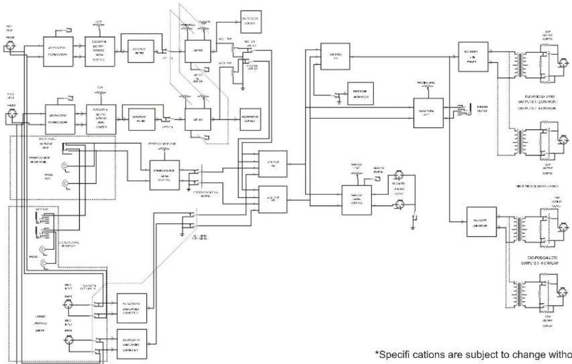
SPECIFICATIONS & BLOCK DIAGRAM\*
Audio Circuit Type: ....Low Noise Active Buffer
Frequency Response: 20Hz to >20KHz (+0/-1.5dB)
Total Harmonic Distortion: ....<0.001% @ +4dB
Dynamic Range: ....>112dB
MICROPHONE
Input Impedance: 7k Ω
Maximum Gain: ....+51dB
Noise Floor: -94dBu
Low-cut Filter: 100Hz (12dB/Octave)
Limiter Threshold: -10dBu to +5dBu Output
Limiter Ratio: ....>20:1
LINE INPUT
Maximum Gain 0dB
PROGRAM
Input Impedance: 22K Ω
Maximum Gain: +19dB
MAIN OUTPUT
Equivalent Input Noise: -111dBu
Clip Level: +24dBu / +17dBu
Output Impedance: 880 Ω
Intermodulation Distortion: 0.002%
GALLERY OUTPUT
Output Impedance: 115 Ohms
Noise Floor (Program in to main out): -80 / -92dBu
Phase Deviation: ....±15°
Microphone Signal Present LED Threshold: -70dBu / -54dBu / -42dBu
Phase Deviation: ±15^
GENERAL
Power: ±15V / +5V Custom Power Supply
Construction: 14 Gauge Steel Chassis & Outer Shell
Finish: Durable Powder Coat
Size: 19" x 7.25" 1.75" (482.6mm x 184.15mm x 44.5mm)
Weight: 6.25lb
flowchart
graph TD
    A["ACV/DCV"] --> B["ACV/DCV"]
    B --> C["ACV/DCV"]
    C --> D["ACV/DCV"]
    D --> E["ACV/DCV"]
    E --> F["ACV/DCV"]
    F --> G["ACV/DCV"]
    G --> H["ACV/DCV"]
    H --> I["ACV/DCV"]
    I --> J["ACV/DCV"]
    J --> K["ACV/DCV"]
    K --> L["ACV/DCV"]
    L --> M["ACV/DCV"]
    M --> N["ACV/DCV"]
    N --> O["ACV/DCV"]
    O --> P["ACV/DCV"]
    P --> Q["ACV/DCV"]
    Q --> R["ACV/DCV"]
    R --> S["ACV/DCV"]
    S --> T["ACV/DCV"]
    T --> U["ACV/DCV"]
    U --> V["ACV/DCV"]
    V --> W["ACV/DCV"]
    W --> X["ACV/DCV"]
    X --> Y["ACV/DCV"]
    Y --> Z["ACV/DCV"]
    Z --> AA["ACV/DCV"]
    AA --> AB["ACV/DCV"]
    AB --> AC["ACV/DCV"]
    AC --> AD["ACV/DCV"]
    AD --> AE["ACV/DCV"]
    AE --> AF["ACV/DCV"]
    AF --> AG["ACV/DCV"]
    AG --> AH["ACV/DCV"]
    AH --> AI["ACV/DCV"]
    AI --> AJ["ACV/DCV"]
    AJ --> AK["ACV/DCV"]
    AK --> AL["ACV/DCV"]
    AL --> AM["ACV/DCV"]
    AM --> AN["ACV/DCV"]
    AN --> AO["ACV/DCV"]
    AO --> AP["ACV/DCV"]
    AP --> AQ["ACV/DCV"]
    AQ --> AR["ACV/DCV"]
    AR --> AS["ACV/DCV"]
    AS --> AT["ACV/DCV"]
    AT --> AU["ACV/DCV"]
    AU --> AV["ACV/DCV"]
    AV --> AW["ACV/DCV"]
    AW --> AX["ACV/DCV"]
    AX --> AY["ACV/DCV"]
*Specifi cations are subject to change without notice.
RADIAL ENGINEERING LTD.
3 YEAR TRANSFERABLE WARRANTY
RADIAL ENGINEERING LTD. ("Radial") warrants this product to be free from defects in material and workmanship and will remedy any such defects free of charge according to the terms of this warranty. Radial will repair or replace (at its option) any defective component(s) of this product (excluding finish and wear and tear on components under normal use) for a period of three (3) years from the original date of purchase. In the event that a particular product is no longer available, Radial reserves the right to replace the product with a similar product of equal or greater value. To make a request or claim under this limited warranty, the product must be returned prepaid in the original shipping container (or equivalent) to Radial or to an authorized Radial repair center and you must assume the risk of loss or damage. A copy of the original invoice showing date of purchase and the dealer name must accompany any request for work to be performed under this limited and transferable warranty. This limited warranty shall not apply if the product has been damaged due to abuse, misuse, misapplication, accident or as a result of service or modification by any other than an authorized Radial repair center.
THERE ARE NO EXPRESSED WARRANTIES OTHER THAN THOSE ON THE FACE HEREOF AND DESCRIBED ABOVE. NO WARRANTIES WHETHER EXPRESSED OR IMPLIED, INCLUDING BUT NOT LIMITED TO, ANY IMPLIED WARRANTIES OF MERCHANTABILITY OR FITNESS FOR A PARTICULAR PURPOSE SHALL EXTEND BEYOND THE RESPECTIVE WARRANTY PERIOD DESCRIBED ABOVE OF THREE YEARS. RADIAL SHALL NOT BE RESPONSIBLE OR LIABLE FOR ANY SPECIAL, INCIDENTAL OR CONSEQUENTIAL DAMAGES OR LOSS ARISING FROM THE USE OF THIS PRODUCT. THIS WARRANTY GIVES YOU SPECIFIC LEGAL RIGHTS, AND YOU MAY ALSO HAVE OTHER RIGHTS, WHICH MAY VARY DEPENDING ON WHERE YOU LIVE AND WHERE THE PRODUCT WAS PURCHASED.
CAUTION: The mPress is equipped with a high output headphone amplifier that is able to drive headphones with impedances that can range from 8 Ohms to 400 Ohms. Prolonged exposure to high sound pressure levels can cause tinnitus or even permanent hearing damage. As the mPress is intended to be used by professionals, it is understood that the user is responsible for proper use. Please consult your local health authority guidelines to ensure you do not put yourself at risk. Radial Engineering Ltd. shall not be held responsible for misuse.
To meet the requirements of California Proposition 65, it is our responsibility to inform you of the following:
WARNING: This product contains chemicals known to the State of California to cause cancer, birth defects or other reproductive harm.
Please take proper care when handling and consult local government regulations before discarding.
All trademarks belong to their respective owners. All references to these are for example only and are not associated with Radial.

Radial Engineering Ltd.
1588 Kebet Way, Port Coquitlam BC V3C 5M5
tel: 604-942-1001 • fax: 604-942-1010
email: info@radialeng.com • web: www.radialeng.com
Radial mPress™ Owner's Manual - Part # R870 1011 00 / 10-2016
Specifications and appearance are subject to change without notice.

CE


- OWNER'S MANUAL
- Radial mPress Owner's Manual
- Modular Press Box
- Table of Contents
- INTRODUCTION
- OVERVIEW
- MAKING CONNECTIONS
- Rear MIC/LINE XLR Inputs
- OPTIMIZING PERFORMANCE
- High-Pass Filter
- Limiter
- ADDING STEREO FEEDS FROM A MUSIC PLAYBACK DEVICE
- CONNECTING THE GALLERY OUTPUTS
- TEST TONE
- Distributing more than two mic signals
- Exo-Pod Modules
- Line Level
- Mic Level
- Star Configuration with Exo-Pods
- Series Configuration with Exo-Pods
- SPECIFICATIONS & BLOCK DIAGRAM\*
- MICROPHONE
- LINE INPUT
- PROGRAM
- MAIN OUTPUT
- GALLERY OUTPUT
- GENERAL
- RADIAL ENGINEERING LTD.
- YEAR TRANSFERABLE WARRANTY
Brand : Radial Engineering
Model : mPress
Category : Professional audio equipment