M-46-FW-V2 - Security Camera i-PRO - Free user manual and instructions
Find the device manual for free M-46-FW-V2 i-PRO in PDF.


| Product Type | Network IP Security Camera |
| Model | M-46-FW-V2 |
| Brand | i-PRO |
| Main Functions | Intelligent detection (cross line, intrusion, face, people counting, auto tracking), PTZ control, edge recording, LPR |
| Video Compression | H.265, H.264, MJPEG |
| Resolution | Up to 3840x2160 (4K) |
| Frame Rate | Up to 25 fps (PAL) |
| Lens Type | Motorized zoom (PTZ model) |
| Network Interface | 1x RJ45 10/100 Base-T (FE Port) |
| Power Supply | DC 12V / PoE (IEEE 802.3af) |
| Power Consumption | Approx. 12W |
| IR Distance | Up to 50m (estimated) |
| Storage | Micro SD card slot (edge storage), FTP, NAS |
| Security | Password protection, HTTPS, 802.1x, SNMPv3 |
| Video Management | Guard Station client software, web interface |
| Operating Temperature | -30°C ~ 60°C (estimated) |
| Ingress Protection | IP66 (estimated) |
| Dimensions | Approx. 150 x 80 x 80 mm (estimated) |
| Weight | Approx. 1.2 kg (estimated) |
| Installation | Ceiling mount, wall mount, desktop mount |
| Warranty | Refer to official documentation |
Frequently Asked Questions - M-46-FW-V2 i-PRO
User questions about M-46-FW-V2 i-PRO
0 question about this device. Answer the ones you know or ask your own.
Ask a new question about this device
Download the instructions for your Security Camera in PDF format for free! Find your manual M-46-FW-V2 - i-PRO and take your electronic device back in hand. On this page are published all the documents necessary for the use of your device. M-46-FW-V2 by i-PRO.
USER MANUAL M-46-FW-V2 i-PRO
Thank you for purchasing our product. If there are any questions, or requests, please do not hesitate to contact the dealer.
Disclaimer

CAUTION!
The default password is intended for your first login. For security, please set a strong password after you first login. A strong password shall include at least nine characters comprising digits, letters, and special characters.
- To the maximum extent permitted by applicable law, the product described, with its hardware, software, firmware and documents, is provided on an “as is” basis.
- Best effort has been made to verify the integrity and correctness of the contents in this manual, but no statement, information, or recommendation in this manual shall constitute formal guarantee of any kind, expressed or implied. We shall not be held responsible for any technical or typographical errors in this manual. The contents of this manual are subject to change without prior notice. Update will be added to the new version of this manual.
- Use of this manual and the subsequent result shall be entirely on the user's own responsibility. In no event shall we be reliable to you for any special, consequential, incidental, or indirect damages, including, among others, damages for loss of business profits, business interruption, or loss of data or documentation in connection with the use of this product.
- Video and audio surveillance can be regulated by laws that vary from country to country. Check the law in your local region before using this product for surveillance purposes. We shall not be held responsible for any consequences resulting from illegal operations of the device.
- The illustrations in this manual are for reference only and may vary depending on the version or model. The screenshots in this manual may have been customized to meet specific requirements and user preferences. As a result, some of the examples and functions featured may differ from those displayed on your monitor.
- This manual is a guide for multiple product models and so it is not intended for any specific product.
- Due to uncertainties such as physical environment, discrepancy may exist between the actual values and reference values provided in this manual. The ultimate right to interpretation resides in our company.
Environmental Protection
This product has been designed to comply with the requirements on environmental protection. For the proper storage, use and disposal of this product, national laws and regulations must be observed.
Symbols
The symbols in the following table may be found in this manual. Carefully follow the instructions indicated by the symbols to avoid hazardous situations and use the product properly.
| Symbol | Description |
 | Contains important safety instructions and indicates situations that could cause bodily injury. |
 CAUTION! CAUTION! | Means reader be careful and improper operations may cause damage or malfunction to product. |
 NOTE! NOTE! | Means useful or supplemental information about the use of product. |
Contents
Disclaimer 2
Environmental Protection 2
Symbols 2
1 Network Connection .... 1
2 Login 1
Preparation 1
Logging In to the Web Interface 3
Introduction to the Web Interface 4
Initial Configuration 5
3 Configuring Parameters....6
Local Parameters 6
Network Configuration 7
Ethernet 7
Port 11
FTP....11
E-Mail 12
Port Mapping 13
DNS 14
DDNS 14
P2P 15
SNMP 15
802.1x 16
QoS 16
Adaptive Streams 17
Image Configuration 18
Image Adjustment.... 18
OSD Setting 27
Privacy Mask 29
Audio and Video Configuration 30
Video Configuration 30
Audio Configuration 32
Snapshot 33
ROI 34
Media Stream Configuration 34
Intelligent Alarm Configuration 36
Smart 36
Cross Line Detection 37
Enter Area 38
Leave Area 39
Intrusion Detection 40
Object Moving 41
Object Left 41
Mixed -Traffic Detection 42
Face 43
Face Picture Comparison 45
Human Body Detection 47
People Counting 48
Auto Tracking 49
Heat Map 49
Defocus Detection 50
Scene Change Detection 51
Advanced Settings 52
Master-Slave Linkage 53
Attribute Collection 56
Common Alarm Configuration 60
Configuring Motion Detection Alarm 61
Configuring Tampering Alarm 63
Configuring Audio Detection Alarm 64
Configuring Alarm Input 66
Configuring Alarm Output 67
Memory Card Storage 68
Setting Cache Post Recording 70
System Maintenance 71
Security 71
Setting the System Time 74
Setting Servers 75
Serial Port Mode Configuration 76
Wiper Control 79
Viewing Device Status 80
Photo Storage Status 80
Upgrading the Device 81
Restarting the System 82
Importing and Exporting System Configuration File 82
Collecting Diagnosis Information 83
Focus Configuration 83
Device Mounting Height 83
Fisheye Camera Parameter 84
4 Live View 85
Live View Toolbar 86
Viewing Certain Area of Images 87
Using Digital Zoom 87
Using Area Focus 88
Using 3D Positioning 89
Face Snapshot 89
Deep Perimeter Snapshot 92
Click Clear All Records to clear the snapshots.Mixed-Traffic Detection Snapshot 93
Live View of Fisheye Cameras 94
5ePTZ of Panoramic Cameras 95
5 Video Playback and Download with Edge Storage 97
Video Playback 97
Download 97
6 PTZ Control 98
PTZ Control Toolbar 98
Setting Patrol by Presets....99
Setting Presets 99
Setting Patrol 100
Setting Home Position 104
Remote Control PTZ 105
PTZ Limit 105
Resume Patrol 106
7 LPR 107
LPR Live View 107
LPR Configuration 107
Appendix A Glossary 110
Appendix B FAQ....111
1 Network Connection
Before accessing a network camera (also known as IP Camera or IPC) from a PC, you need to connect the network camera to the PC directly with a network cable or via a switch or router.
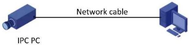
flowchart
graph LR
    A["IPC PC"] -->|Network cable| B["Computer"]
Use a Shielded Twisted Pair (STP) cable to connect the network interfaces of the network camera and the PC.
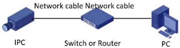
flowchart
graph LR
    A["IPC"] --> B["Switch or Router"]
    B --> C["PC"]
Use Shielded Twisted Pair (STP) cables to connect the network interfaces of the camera and the switch or router.
2 Login
Preparation
After you have completed the installation in accordance with the quick guide, connect the camera to power to start it. After the camera is started, you can access the camera from a PC client installed with a web browser or the client software Guard Station. Internet Explorer(IE) is a recommended web browser. For more information about Guard Station, refer to the Guard Station User Manual.
The following takes IE on a Microsoft Windows7 operating system as an example.
Check before login
• The camera is operating correctly.
• The network connection between the PC and the camera is normal.
• The PC is installed with Internet Explorer 10.0 or higher.
• (Optional) The resolution is set to 1440 x 900.
Add the IP address as a trusted site
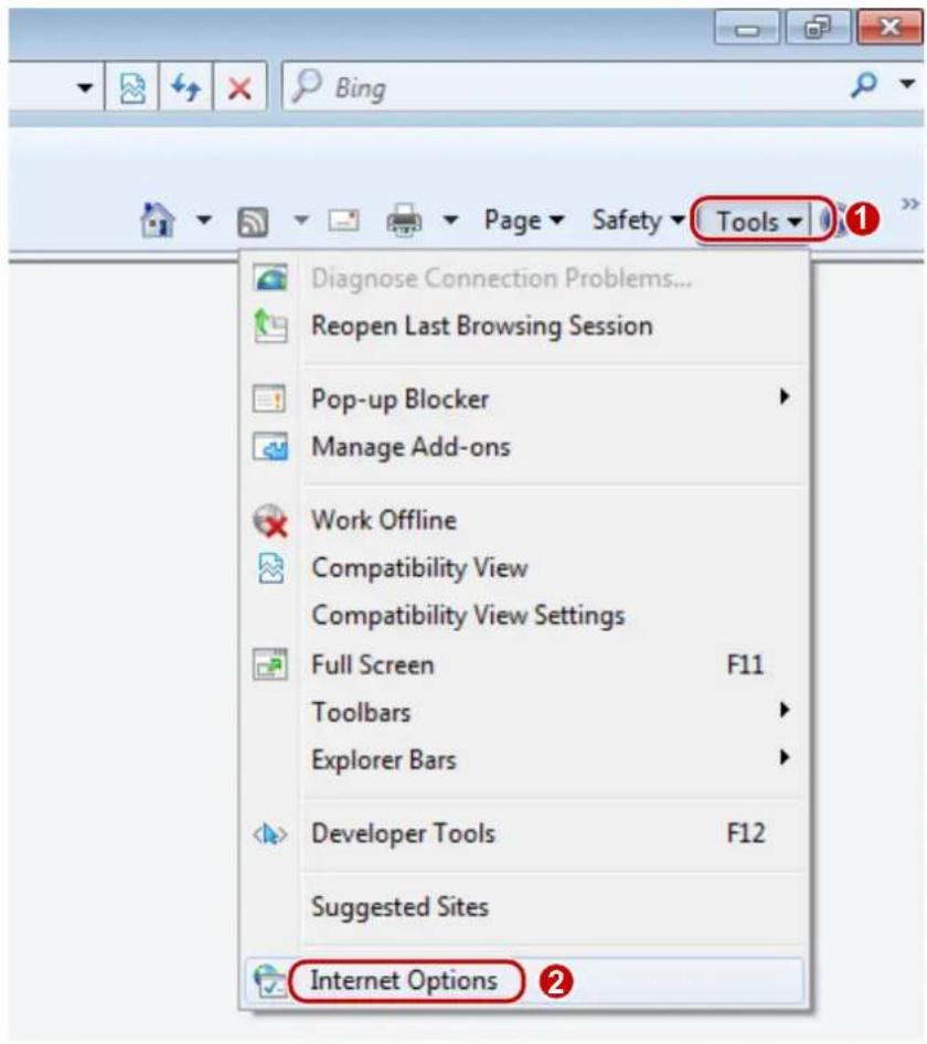
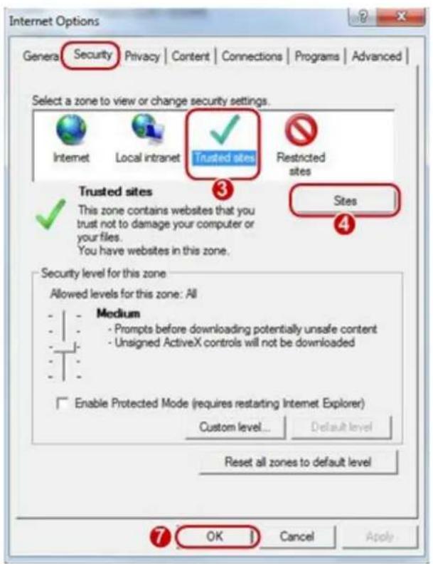
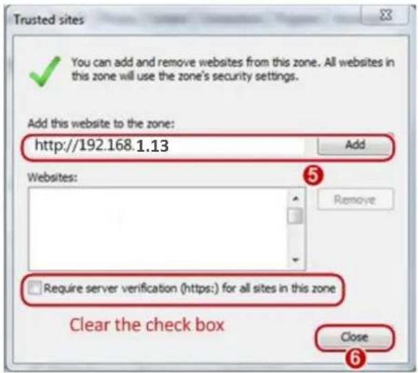
NOTE!
The IP address 192.168.1.13 in this example is the default IP address. Please replace it with the actual address of your camera if it has been changed.
(Optional) Modifyuser access control settings
Before you access the camera, follow the steps to set User Account Control Settings to Never notify.
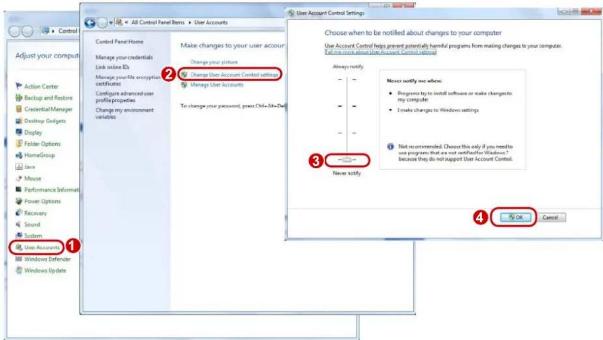
Logging In to the Web Interface
The default static IP address of the camera is 192.168.1.13, and the default subnet mask is 255.255.255.0.
DHCP is turned on by default. If a DHCP server is used in the network, the IP address of your camera may be assigned dynamically, and you need to use the correct IP address to log in. Use the Guard Station client to view the dynamic IP address of your camera.
The following takes IE as an example to describe the login procedure.
- Browse to the login page by entering the correct IP address of your camera in the address bar.

- If you log in for the first time, follow system prompts and install the ActiveX. You need to close your browser to complete the installation.

NOTE!
- To manually load the ActiveX, typehttp://IP address/ActiveX/Setup.exe in the address bar and press Enter.
- The default password is intended for your first login. For security, please set a strong password after your first login. A strong password shall include at least nine characters comprising digits, letters, and special characters.
-
The camera protects itself from illegal access by limiting the number of failed login attempts. If login fails six times consecutively, the camera locks automatically for ten minutes.
-
Privacy policy is displayed on the screen when the user logs in for the first time. After reading the privacy policy, you need to check in the 'I have read and agree to the above policy' box, then click the 'OK' button to proceed to the next step.
Privacy Policy
Privacy Policy of Uniview Technologies
Introduction
Uniview Technologies highly emphasizes protection of users' personal information and privacy, and to this end we established this Privacy Policy to inform users how their information is collected, used, shared, stored, and protected. With this Privacy Policy, you will get to know the ways of processing your personal information by us. This Privacy Policy is closely related to the use of products and / services of Uniview Technologies by you, and you shall carefully read and fully understand this Privacy Policy, and make proper choices based on your judgment accordingly, before you use any products and/or services of Uniview Technologies. You should stop using any products and/or services of Uniview Technologies immediately if you disagree with any content in this Privacy Policy. The use of any product and/or service of Uniview Technologies by you will be considered that you agree and fully understand entire content of this Privacy Policy. ("Uniview Technologies" and "we/us" referred to hereinafter all represent "Zhejiang Uniview Technologies Co., Ltd.")
I. Scope of Information Collection
Personal information and non-personal information of the user, resident and yourself may be collected by us when products and/or services of Uniview Technologies are used by you.
Personal information refers to any information that relates to certain natural person and that may be used to identify certain natural person when combined with other information, including but not limited to name, gender, date of birth, domicile, telephone number, E-mail address, mailing address, payment information, and personal video content.
Non-personal information refers to, other than personal information, data that no direct connection to any specific person may be determined by solely relying on such data, such as profession, language, zip code, area code, serial number, URL, automatically recorded access data (e.g., type of
I have read and agree to the above policy

-
Enter the username and password, and then click Login. For the first login, use the default username "admin" and password "123456".
-
If you log in with Save Password selected, you do not need to enter the password each time when you log in. To ensure security, you are not advised to select Save Password.
• To clear the Username and Password text boxes and the Save Password checkbox, click Reset.
Introduction to the Web Interface
By default the live view window is displayed when you are logged in to the Web interface. The following shows an example.
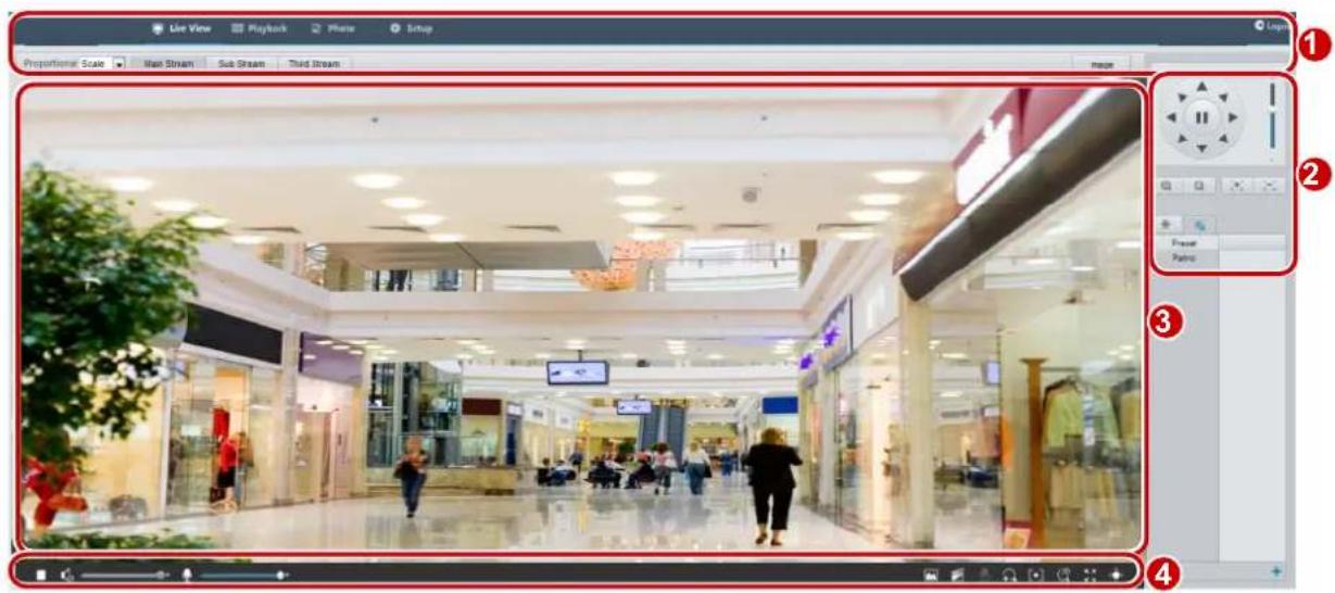
| No. | Description |
| 1 | Menu |
| 2 | PTZ control areaNote:This area is available for PTZ dome cameras and PTZ cameras. |
| 3 | Live view window |
| 4 | Live view toolbar |
Initial Configuration
After you log in to the device, please perform the following initial configuration.
| Item | Description |
| 1. Ethernet. | Reconfigure the device IP and network parameters based on the actual networking. |
| 2. Log out and log in again to the Web using the new IP address. | - |
| 3. Set the system time. | Set the system time based on the actual situation. |
| 4. (Optional) Set the management server. | Set the management server based on the actual networking. |
| 5. (Optional) Set the server for storing photos. | Set the server for storing photos based on the actual networking. |
| 6. Set OSD. | Set the information displayed on the screen as needed, for example, time. |
| 7. (Optional) Manage users. | Change the default password and add common users as needed. |
You can watch the live video after finishing the initial configuration. Please configure other parameters as needed.

NOTE!
- The displayed live view interface, parameters displayed and value ranges may vary with models. Please see the actual Web interface for details.
- The parameters that are grayed out cannot be modified. For the actual settings, see the Web interface.
- It is recommended that you change the password when you are logged in the first time. For details about how to change a password, see Security.
3 Configuring Parameters
Local Parameters
Set local parameters for your PC.

NOTE!
The local parameters may vary with models. Please see the actual Web interface for details.
1. Select Setup>Common>Local Parameters
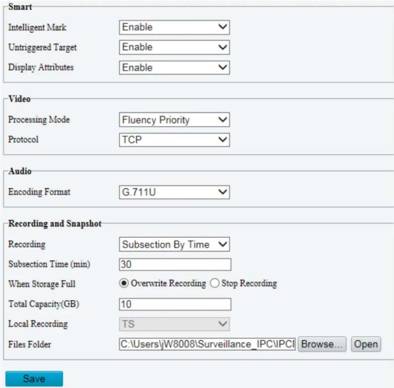
- Modify the settings as required. The following table describes some major parameters.
| Parameter | Description | |
| Smart | Untriggered Target | When enabled, the camera will display an on-screen mark on the target (e.g., face when face detection is enabled) and track it. |
| Intelligent Mark | This function should be used with“Cross Line Detection、Enter Area、Leave Area、Intrusion Detection、Mixed -Traffic Detection” | |
| Display Attributes | When enabled, the attributes collected will be displayed in live view page.This function should be used with Intelligent >Smart >Attribute Collection. | |
| Video | Processing Mode | Real-Time Priority: Recommended if the network is in good condition.Fluency Priority: Recommended if you want short time lag for live video.Ultra-Low Delay: Recommended if you want the minimum time lag for live video. |
| Protocol | Set the protocol used to transmit media streams to be decoded by the PC. | |
| Record and Snapshot | Recording | Subsection By Time: Duration of recorded video for each recording file on the computer. For example, 2 minutes.Subsection By Size: Size of each recording file stored on the computer. For example, 5M. |
| Record Overwrite | Overwrite: When the assigned storage space on the computer is used up, the camera deletes the existing recording files to make room for the new recording file.Full Stop: When the assigned storage space on the computer is full, recording stops automatically. | |
| Files Folder | The save path of snapshots and recordings. The max. path length is 260 bytes. If the limit is exceeded, recording or snapshot during live view will fail, and messages will appear on the screen. | |
3. Click Save.
Network Configuration
Ethernet
Modify communication settings such as the IP address for the camera so that the camera can communicate with other devices.

NOTE!
• After you have changed the IP address, you need to use the new IP address to log in.
- The configurations of DNS (Domain Name System) server are applicable when the device is accessed by domain name.
Static Address
- Click Setup>Network>Network.
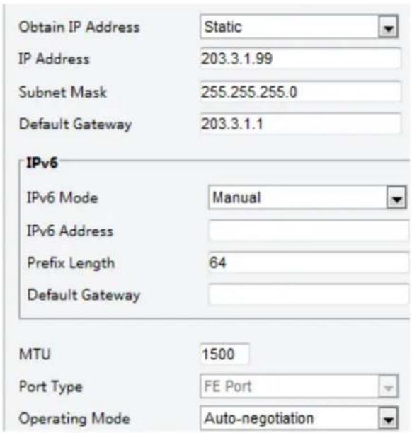
- Select Static from the Obtain IP Address drop-down list.
- Enter the IP address, subnet mask, and default gateway address. Make sure that the IP address of the camera is unique in the network.
- Click Save.
PPPoE

NOTE!
This function is not supported by some models. Please see the actual model for details.
If the camera is connected to the network through Point to Point over Ethernet (PPPoE), you need to select PPPoE as the IP obtainment mode.
- Click Setup>Network>Network.
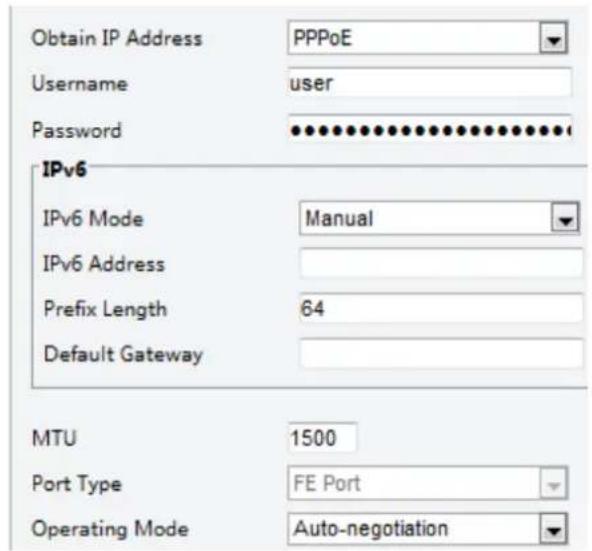
- Select PPPoE from the Obtain IP Address drop-down list.
- Enter the username and password provided by your internet Service Provider (ISP).
- Click Save.
DHCP
The Dynamic Host Configuration Protocol (DHCP) is enabled by default when the camera is delivered. If a DHCP server is deployed in the network, the camera can automatically obtain an IP address from the DHCP server.
To manually configure DHCP, follow the steps below:
- Click Setup>Network>Network.
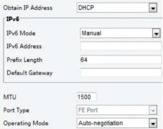
-
Select DHCP from the Obtain IP Address drop-down list.
-
Click Save.
IPv6
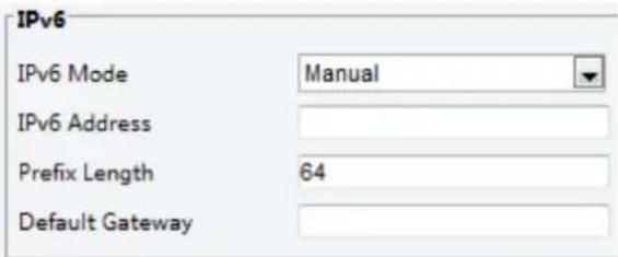
- Click Setup>Network>Network.
-
By default the IPv6 mode is set to Manual.
-
Enter the IPv6 address, set the prefix length and default gateway. The IP address must be unique on the network.
-
Click Save.
Wi-Fi

NOTE!
This function is not supported by some models, please see the actual model for details.
- Click Setup>Network>Network. Click the Wi-Fi tab.
Wi-Fi Mode
Sniffer
-
Select Sniffer.
-
Click Save.
Some devices can search for Wi-Fi networks and connect.
- Select Setup> Network>Network. Select Wi-Fi for Wi-Fi Mode.
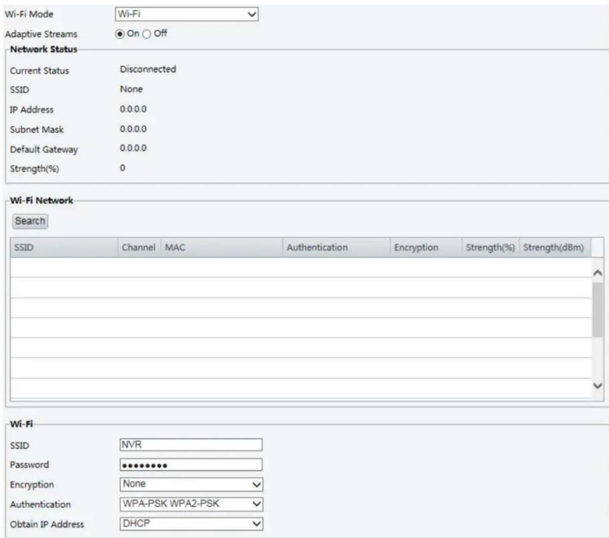
- Signal strength is displayed. Turn on Adaptive Streams. The page shows that there are other Wi-Fi networks. To search for Wi-Fi networks again, click Search.
- Click an SSID in the Wi-Fi Network list. Information about the corresponding network is displayed.
- Click Save.
- When Wi-Fi Mode is set to Wi-Fi Hotspot, the camera can function as a Wi-Fi hotspot for other devices.
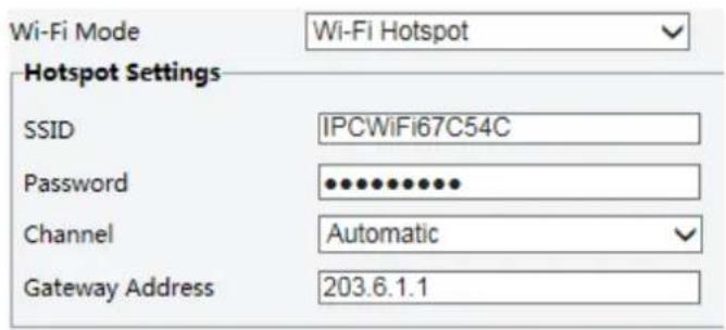
- Click Save.

NOTE!
This function is not supported by some models. Please see the actual model for details.
1. Click Setup>Network>Port.
| HTTP Port | 80 |
| HTTPS Port | 443 |
| RTSP Port | 554 |
Note: Modifying the RTSP or server port number will cause the device to restart.
- Configure relevant port numbers.
- Click Save.
FTP
All snapshots (except face detection) are saved through the general FTP service. After the configuration of FTP, you will be able to upload snapshots from network cameras to the specified FTP server.
General
1. Click Setup>Storage>FTP. Go to General tab.

![Snapshot Image Save To[ Preset No. ] [IP Address] [Date] [Hour(s)] Root Directory Preset No. ✓ \\ IP Address ✓ \\ Date ✓ \\ Hour(s) ✓ File Name[Preset No.]-[PTZ Zoom]-[PTZ Latitude]-[PTZ Longitude].jpg Separator - No. Naming Element 1 Preset No. ✓ 2 PTZ Zoom ✓ 3 PTZ Latitude ✓ 4 PTZ Longitude ✓ 5 None ✓](/content/2026/05/958465/images/9c0c8a7c5e2148e5731de94d51371e7cfd061943e51e9939ef80f936ef8a211b.jpg)
- Set the IP address and port for the FTP server, username and password used to upload images to the FTP server, select Upload Images, Overwrite Storage and set Overwrite At (threshold for overwriting images). Some camera models support FTP test. You may test FTP after completing FTP settings correctly.
- Set the path for saving snapshots on the FTP server and the file name format. For example, set path as Preset No.\IP Address\Date\Hour(s), and set file name as Preset No.-PTZ Zoom-PTZ Latitude-PTZ Longitude.jpg.
- Click Save.
Smart
This function is used to store snapshots taken for smart functions such as face recognition. To use smart FTP, click Setup > System > Server > Intelligent Server and set Platform Communication Type to FTP.
- Click Setup>Storage>FTP. Go to Smart tab.
![Server Parameters Server IP 192.168.0.150 Custom Naming Rules Port No. 21 Convert Path into UTF8 Format Username Password Device Name Device ID 1 Intersection ID Snapshot Image Save To\ [Preset No.\ [IP Address]\ [Date] Root Directory Preset No. \ IP Address \ Date File Name[Preset No.]-[PTZ Latitude]-[PTZ Longitude]-[PTZ Zoom].jpg Separator - No. Naming Element Naming Rule 1 Preset No. 2 PTZ Latitude 3 PTZ Longitude 4 PTZ Zoom 5 None](/content/2026/05/958465/images/f2260a79121b15068a526aa622b9d7a1d43565b70968c10fd428e31399d7d249.jpg)
- Set the IP address and port of the FTP server, username and password used to upload images to the FTP server.
- Set the path for saving snapshots on the FTP server and the file name format. For example, set path as Preset No.\IP Address\Date, and set file name as Preset No.-PTZ Latitude-PTZ Longitude-PTZ Zoom.jpg.
- Click Save.
After the configuration of E-mail, when alarms are triggered, you will be able to send messages to the specified E-mail address.
- Click Setup>Network>E-mail.
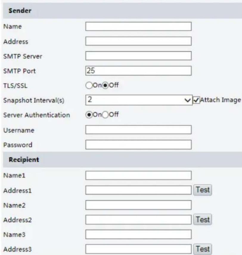
- Configure relevant parameters of the sender and the recipient. Some camera models support Email test. You may test email after setting the recipient address. The following table describes some major parameters.
| Parameter | Description |
| TLS/SSL | When enabled, the e-mail will be encrypted using TLS (Transport Layer Security) or Secure Socket Layer (SSL) to protect privacy.First it tries to send through an SSL connection. If the SMTP server supports SSL, the e-mail will be sent through the SSL connection; otherwise, it tries to send using STARTTLS. |
| Attach Image | When enabled, the e-mail will contain 3 instant snapshots as attachment according to the Capture Interval. |
| Username/Password | Username and password of the registration email address. The password allows the following special characters \ / : * ? ' " <> | % & |
- Click Save.
Port Mapping
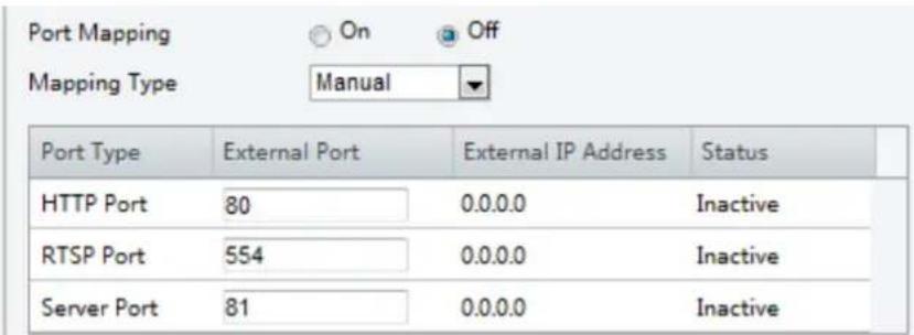
- Click Setup>Network>Port. Go to Port Mapping tab.
-
Enable Port Mapping and select mapping type. If Manual is selected, then external ports must be configured (external IP is obtained automatically by the camera). If the configured port is occupied, then the Status will show Inactive.
-
Click Save.
DNS
- Click Setup>Network>DNS.
| Preferred DNS Server | 8.8.8.8 |
| Alternate DNS Server | 8.8.4.4 |
-
Set DNS server addresses.
-
Click Save.
DDNS

NOTE!
This function is not supported by some models. Please see the actual model for details.
- Click Setup>Network>DDNS.
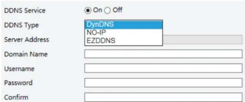
- Enable DDNS Service.
- Select a DDNS type: DynDNS, NO-IP, or EZDDNS.
- Complete other settings including server address, domain name, username and password.
- Click Save.

NOTE!
• This function is not available to all models.
- Scan the QR code with your mobile phone (iOS or Android) to download the APP.
- When installed, run the APP to add the camera. Please refer to the online help in the APP for detailed steps.
1. Click Setup>Network>P2P>Star4live.
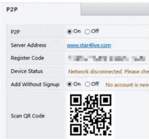
- Select On to enable cloud service.
- Click Save.
SNMP
SNMPv3 is recommended when a camera needs to transfer configuration with the central server. Both the camera and the central server should support SNMPv3.

NOTE!
- Two options are available: SNMPv3 (default) and SNMPv2.
-
If you choose SNMPv2, an onscreen message will remind you of potential risks and ask if you want to continue.
-
Click Setup> Network > SNMP
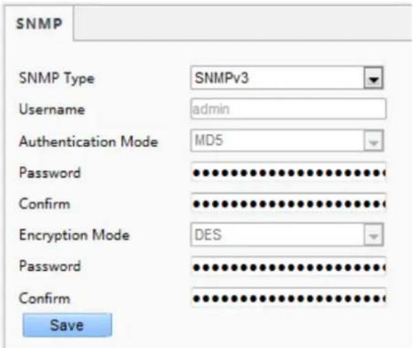
- Select SNMPv3 and complete settings.
- Click Save.
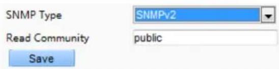
On the SNMPv2 setting page, Read-Only Community Name is used for two-way authentication between a camera and the central server. The default name is public, and you may change it as needed.
If you change thRead-Only Community Name you should change it into the same one on the central server, or the two-way authentication will not be completed.
802.1x
802.1x provides authentication to devices (e.g., cameras) trying to connect to a network. Only the authenticated devices can connect the network. This enhances security.
- Click Setup>Network>802.1x.
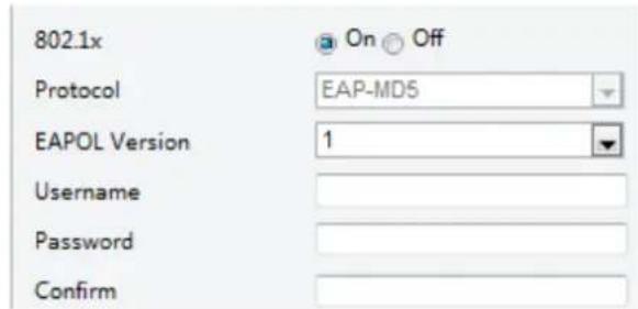
- Select On and then complete other settings.
- Click Save.
QoS
QoS(Quality of Service) is the ability to provide better service for specified network communication. As a network security mechanism, QoS is used to address problems like network delay and blocking.
When the network is overloaded or congested, QoS ensures that critical services are not delayed or discarded and that the network runs efficiently.
1. Click Setup > Network > QoS.
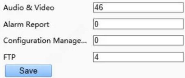
- Set a priority level (0\~63) for each service. At present, QoS allows you to assign different priority to audio and video, alarm report, configuration management and FTP transmission. The greater the value, the higher the priority. For example, if the value of audio and video is set to 60, alarm report and configuration management is set to 0, and FTP is set to 4, when network congestion occurs, the priority is to ensure the smooth running of audio and video.
3. Click Save.

Note: To use QoS, make sure that the switch support QoS mode.
Adaptive Streams

NOTE!
- Adaptive Streams is not available on all models, and is enabled by default on some models. Please see the actual Web interface for details.
- Itss recommended to enable Adaptive Streams in a poor network environment.
1. Click Setup > Network > Wi-Fi, and set Wi-Fi Mode to Wi-Fi.
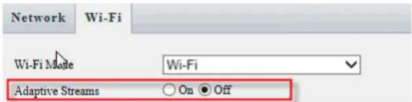
- Enable Adaptive Streams.
- Click Save.
Image Configuration
Image Adjustment

NOTE!
- The image parameters displayed and value ranges allowed may vary with camera model. For the actual parameters and value ranges of your camera, see the Web interface. You may move the sliders to adjust settings or enter values in the text boxes directly.
- Clicking Default will restore all the default image settings.
Setting the Scene
Set image parameters to achieve the desired image effects based on live video in different scenes.
Click Setup>Image>Image.
The scene management page for some models is displayed as follows, you can select the desired scene in the drop-down list.

The scene management page of some models is displayed as follows, you can take the following steps to configure the scene.
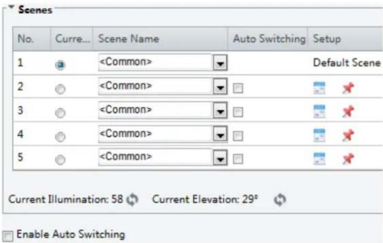
- Click Scenes.
- Select a scene, and then set scene switching parameters. The following table describes some major parameters.
| Column | Description |
| Current | Indicates the scene that is being used.Note:Select an option button to switch to the scene and display the corresponding image parameters for the scene.The camera switches the current scene automatically when Enable Auto Switching is selected. |
| Scene Name | Name of the current scene. The device provides several preset scene modes. When yo select a scene, the corresponding image parameters are displayed. You can adjust image settings according to actual needs.Common: recommended for outdoor scenes.Indoor: recommended for indoor scenes.High Sensitivity: recommended for low light environment.Highlight Compensation: can suppress strong light such as headlights on roads and spotlight in parks. Recommended for capturing vehicle license plates.WDR:recommended for scenes with high-contrast lighting, such as window, corridor, front dooror other scenes that are bright outside but dim inside.Custom: set a scene name as needed.Face: Capture faces in motion in complicated scenes. |
| Auto Switching | Indicates whether to add a scene to the auto-switching list.Note:If Auto Switching is selected, the system switches to a scene automatically when the condition for switching to the scene is met. By default the auto-switching list includes the default scene. |
| Setup | Clickto set conditions for auto-switching, including schedule, illumination, and current elevation (angle between the PTZ and the horizontal direction). It means that auto-switching is triggered only when illumination and the current elevation during the set time period meet the set conditions. A condition is invalid if both the start and end values are set to 0. |
- Select a scene and then click ✗ to set it as the default scene.
- If auto-switching is enabled, the camera can switch to the scene automatically when the condition for switching to a non-default scene is met. Otherwise, the camera remains in the default scene. When auto-switching is not enabled, the camera remains in the current scene.

NOTE!
- If Auto Switching is enabled (scene settings will be unavailable), the device will switch between the set scenes. If not, the device will stay at the current scene. The device will stay at default scenes unless the non-default scenes are triggered.
- If multiple non-default scenes are triggered, then the device will switch to the scene with the minimum number (starts from 1 to 5).
Image Enhancement

NOTE!
This function may vary with models. Please see actual Web interface for details.
1. Click Setup>Image>Image and then click Image Enhancement.

- Use the sliders to change the settings. You may also enter values directly. The following table describes some major parameters.
| Item | Description | |
| Brightness | Set the degree of brightness of images. | |
 |  | |
| Low brightness | High brightness | |
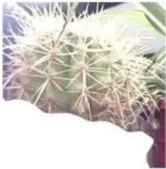
| Saturation | The amount of a hue contained in a color. | |
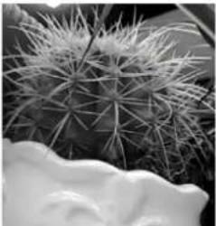 | 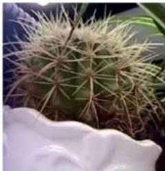 | |
| Low saturation | High saturation | |
| Contrast | Set the degree of difference between the blackest pixel and the whitest pixel. | |
 |  | |
| Low contrast | High contrast | |
| Sharpness | Contrast of boundaries of objects in an image. | |
 |  | |
| Low sharpness | High sharpness | |
| 2D Noise Reduction | Reduce the noise of images. The function may cause image blurring. | |
| 3D Noise Reduction | Reduce the noise of images. The function may cause motion blur (or ghosting in some applications). | |
| Image Rotation | Rotation of the image. | |
 |  | |
| Normal | Flip Vertical | |
 |  | |
| Flip Horizontal | 180° | |
 |  | |
| 90°Clockwise | 90°Anti-clockwise | |
- To restore default settings in this area, click Default.
Exposure

NOTE!
• This function may vary with models. Please see actual Web interface for details.
- The default settings are scene-adaptive. Use default settings unless modification is necessary.
- Click Setup>Image>Image and then click Exposure.
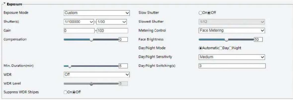
For some camera models, the page is displayed as follows.
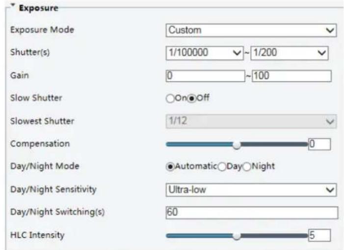
- Set the parameters as required. The following table describes some major parameters.
| Parameter | Description |
| Exposure Mode | Select the correct exposure mode to achieve the desired exposure effect.Automatic: The camera automatically adjusts exposure according to the environment.Custom: The user sets exposure as needed.Indoor 50Hz: Reduce stripes by limiting shutter frequency.Indoor 60Hz: Reduce stripes by limiting shutter frequency.Manual: Finetune image quality by setting shutter, gain and iris manually.Low Motion Blur: Control the minimum shutter to reduce motion blur in faces captured in motion. |
| Shutter (s) | Shutter is used to control the light that comes into the lens. A fast shutter speed is ideal for scenes in quick motion. A slow shutter speed is ideal for scenes that change slowly.Note:You can set a shutter speed when Exposure Mode is set to Manual or Shutter Priority.If Slow Shutter is set to Off, the reciprocal of the shutter speed must be greater than the frame rate. |
| Gain (dB) | Control image signals so that the camera outputs standard video signals according to the light condition.Note:You can set this parameter only when Exposure Mode is set to Manual or Gain Priority. |
| Slow Shutter | Improves image brightness in low light conditions.Note:You can set this parameter only when Exposure Mode is not set to Shutter Priority and when Image Stabilizer is disabled. |
| Slowest Shutter | Set the slowest shutter speed that the camera can use during exposure.Note:You can set this parameter only when Slow Shutter is set to On. |
| Compensation | Adjust the compensation value as required to achieve the desired effects.Note:You can set this parameter only when Exposure Mode is not set to Manual. |
| Metering Control | Set the way the camera measures the intensity of light.• Center-Weighted Average Metering: Measure light mainly in the central part of images.• Evaluative Metering: Measure light in the customized area of images.• Highlight compensation: Ignore the brightness of the overexposed area of images. But selecting this setting will decrease the overall brightness of the image.• Face Metering: Adjust image quality in poor lighting conditions by controlling the brightness of captured face in Face scene.Note:You can set this parameter only when Exposure Mode is not set to Manual. |
| Day/Night Mode | • Automatic: The camera outputs the optimum images according to the light condition. In this mode, the camera can switch between night mode and day mode automatically.• Night: The camera provides high-quality black and white images using the existing light• Day: The camera provides high-quality color images using the existing light. |
| Day/Night Sensitivity | Light threshold for switching between day mode and night mode. A higher sensitivity means that the camera is more sensitive to the change of light and becomes more easily to switch between day mode and night mode.Note:You can set this parameter only when Day/Night Mode is set to Automatic. |
| Day/Night Switching(s) | Set the length of time before the camera switches between day mode and night mode after the conditions for switching are met.Note:You can set this parameter only when Day/Night Mode is set to Automatic. |
| WDR | Enable WDR to distinguish the bright and dark areas in the same image.Note:You can set this parameter only when Exposure Mode is neither Customize nor Manual and when Image Stabilizer is disabled. |
| WDR Level | After enabling the WDR function, you can improve the image by adjusting the WDR level.Note:Use level 7 or higher when there is a high contrast between the bright and dark areas of the scene. In the case of low contrast, it is recommended to disable WDR or use level 1-6. |
| Suppress WDR Stripes | When enabled, the camera can automatically adjust slow shutter frequency according to the frequency of light to minimize stripes that may appear in images. |
- To restore the default settings, click Default.

NOTE!
This function may vary with models. Please see actual Web interface for details.
1. Click Setup>Image>Image and then click Smart Illumination.
| Smart Illumination | |||
| Smart Illumination | ●On○Off | Control Mode | Manual |
| Lighting Type | Infrared | Near-illumination Level | 0 |
| Mid-illumination Level | 0 | Far-illumination Level | 0 |
2. Select the correct IR control mode and set the parameters. The following table describes some major parameters.
| Parameter | Description |
| Lighting Type | Infrared: The camera uses infrared light illumination.White Light: The camera uses white light illumination.Note:When Control Mode is set to Manual, camera can set illumination level from 0~1000. |
| Control Mode | Global Mode: The camera adjusts IR illumination and exposure to achieve balanced image effects. Some areas might be overexposed if you select this option. This option is recommended if monitored range and image brightness are your first priority.Overexposure Restrain: The camera adjusts IR illumination and exposure to avoid regional overexposure. Some areas might be dark if you select this option. This option is recommended if clarity of the central part of the image and overexposure control are your first priority.Road: This mode offers strong illumination in whole and is recommended for monitoring wide-ranging scenes, for example, road.Park: This mode offers uniform light and is recommended for monitoring small range scenes with many obstacles, for example, industrial parks.Manual: This mode allows you to manually control the intensity of IR illumination.Indoor: This mode is recommended for application in indoor scenes. |
| Illumination Level | Set the intensity level of the IR light. The greater the value, the higher the intensity. 0 means that the IR light is turned off.Near-illumination Level: You are recommended to set this parameter first for a wide-angle scene.Mid-illumination Level: You are recommended to set this parameter first if the scene requires an intermediate focal length.Far-illumination Level: You are recommended to set this parameter first if the scene requires a telephoto view.Note:You can set this parameter only when Control Mode is set to Manual. |
3. To restore the default settings, click Default.
Focus

NOTE!
This function may vary with models. Please see actual models for details.
1. Click Setup>Image>Image and then click Focus.
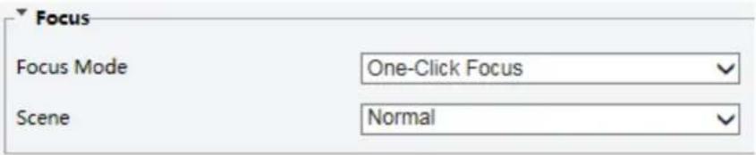
2. Select the focus mode as required.
| Parameter | Description |
| Focus Mode | Auto Focus: The camera focuses automatically according to the current light condition.Manual Focus: Manually adjust camera focus as required.One-Click Focus: The camera is triggered to focus once when rotating, zooming or going to a preset.One-Click Focus (IR): In a low light condition such as during night hours or in a dark house, this focus mode achieves better effects with the IR light turned on. |
| Scene | Normal: Used for common scenes, such as road and industrial park.Long Distance: Used for long-distance monitoring on a road. For example, when the camera is installed over 30 meters high to monitor a distant road intersection. |
3. To restore the default settings, click Default.
White Balance
White balance is the process of offsetting unnatural color cast in images under different color temperatures so as to output images that best suit human eyes.

NOTE!
This function may vary with models. Please see the actual Web interface for details.
1. Click Setup>Image>Image and then click White Balance.
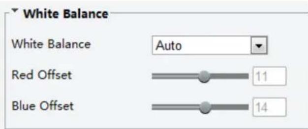
2. Select a white balance mode as required. The following table describes some major parameters.
| Parameter | Description |
| White Balance | Adjust the red or blue offset of the image:Auto/Auto2: The camera adjusts the red and blue offset automatically according to the light condition (the color tends to be blue). If the images are still unnaturally red or blue in Auto mode, please try Auto2.Fine Tune: Allow you to adjust the red and blue offset manually.Outdoor: Suitable for outdoor environment with a relatively greater color temperature range.Locked: Lock the current color temperature without change.Sodium Lamp: The camera adjusts red and blue offset automatically according to the light condition (the color tends to be red). |
| Red Offset | Adjust the red offset manually.Note:You can set this parameter only when White Balance is set to Fine Tune. |
| Blue Offset | Adjust the blue offset manually.Note:You can set this parameter only when White Balance is set to Fine Tune. |
3. To restore the default settings, click Default.
Advanced
Use the defog function to adjust the clarity of images captured in fog or haze conditions.
1. Click Setup>Image>Image and then click Advanced.
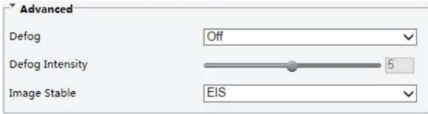

NOTE!
• You can set this parameter only when WDR is turned off.
- Only some camera models support optical defog. When Defog is set to On, defog intensity level 6-9 represent optical defog, and images change from color to black/white when defog intensity is set from level 5 to 6; if Defog is set to Auto and defog intensity level is somewhere between 6-9, images do not automatically change to black/white in light fog conditions; the camera automatically switches to optical defog only in heavy fog conditions.
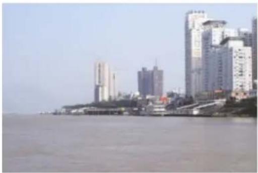
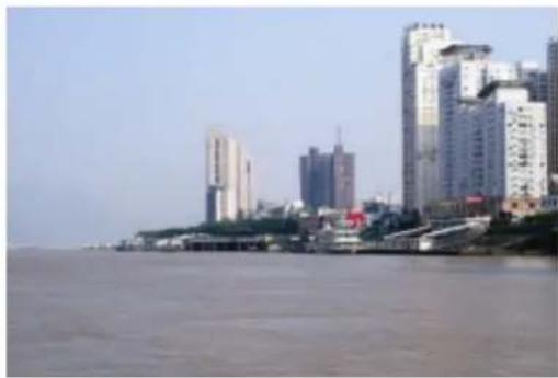
2. Enable the defog function and then select a level for the scene. Level 9 achieves the maximum defog effects, and level 1 achieves the minimum.
natural_image
Cityscape with modern high-rise buildings along a waterfront promenade (no visible text or signage)Defog Off
natural_image
Cityscape with modern high-rise buildings along a riverbank, no visible text or signageDefog On
3. To restore the default settings, click Default.
Lighting Type

NOTE!
This function may vary with models. Please see the actual model for details.
1. Click Setup>Image>Image and then click Smart Illumination
-
Select an option from the Lighting Type drop-down list.
-
To restore the default settings, click Default.
Configuring Iris and Lens Mode

NOTE!
- This function is only supported by certain network box camera types. Please see the actual model for details.
- Please use the lens with P-Iris control mode, and connect the iris control cable to the Z/F port of the camera.
- Iris can be set only when Lens Mode is set to P-IRIS.
1. Click Setup>Image>Image and then click Advanced.

2. Modify the settings as required. The following table describes some major parameters.
| Parameter | Description |
| Lens Mode | Z/F: to modify focus and zoom.P-Iris: to modify iris value. |
| Aperture Control | Automatically or manually adjust iris.Note:You can set this parameter only when Lens Mode is set to P-Iris. |
| F-Number | Change aperture manually. |
3. To restore the default settings, click Default.
OSD Setting
On Screen Display (OSD) is the text displayed on the screen with video images and may include time and other customized contents.

NOTE!
This function may vary with models. Please see the actual Web interface for details.
1. Click Setup>Image>OSD.
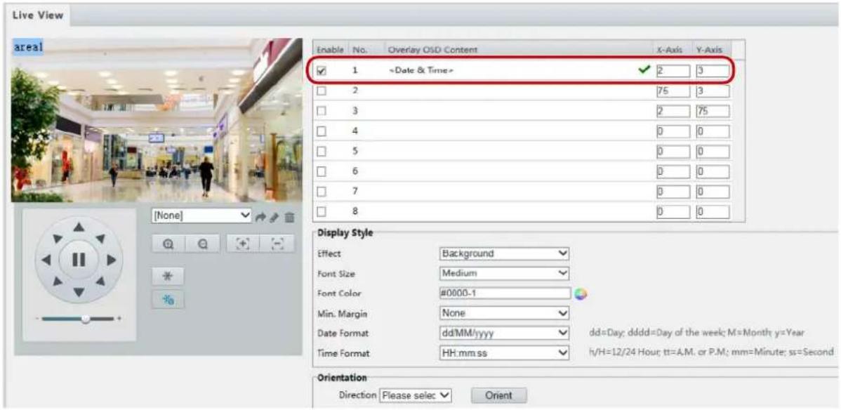
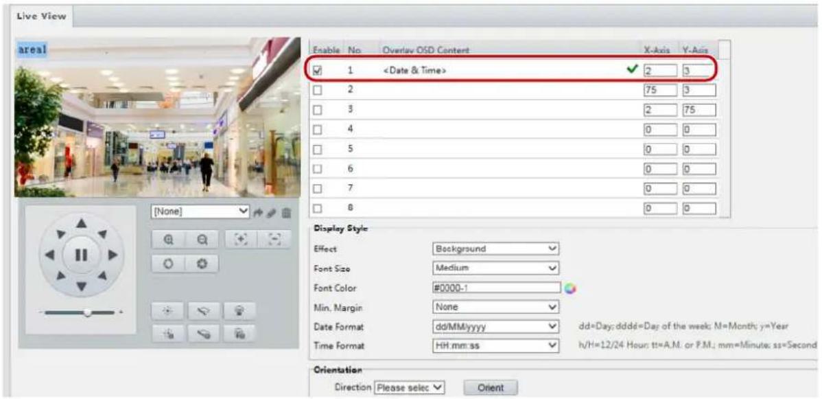
The OSD interface of some models is displayed as follows.
-
Select the position and content of the OSD.
-
Position: Click the desired box in the Live View area. After the cursor shape is changed, click and hold the button to move the box to the desired position. To set the position precisely, use the X and Y coordinates under Overlay Area.
- Overlay OSD Content: The drop-down list provides Time, Preset and Serial Info. You may also select Custom and enter the content you want.
-
After you have set the position and OSD content, the √ symbol appears in the Status column, which means that the OSD is set successfully. You may set multiple lines of contents for each area and use ∧ and ∨ to adjust the sequence of display.
-
After you have completed the settings, a message appears to indicate the successful settings.
You may right-click in the preview window and then choose to view in full screen mode or at an aspect ratio. You may also double-click the preview window to enter or exit full screen mode.
To cancel OSD for an area, clear the OSD content in the Overlay OSD Content column or select None in the Position column.
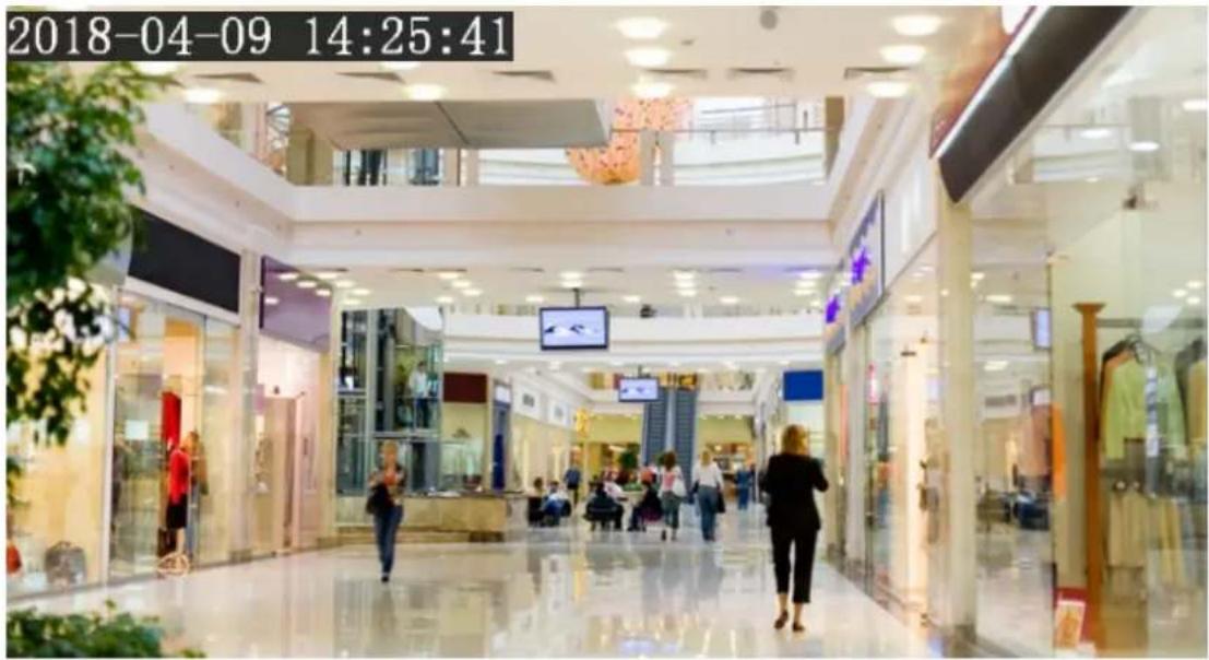
The following shows an example time OSD.
Privacy Mask
On certain occasions, you may need to set a mask area on the camera image to protect privacy, for example, the keyboard of an ATM machine. When PTZ changes its position or zooms, the Privacy Mask will be adjusted accordingly to protect the area all along.

NOTE!
• This function may vary with models. Please see the actual Web interface for details.
• Some models support up to 24 privacy masks. The same picture shows up to only 8 privacy masks.
1. Click Setup>Image>Privacy Mask.
![Privacy Mask Add Delete No. Name Max Zoom Operation 1 Mask1 1.00 [None]](/content/2026/05/958465/images/cf18c12d288e7f702297674a467601364e559ab371fbe4b04092fd9544f9f2cd.jpg)
For some camera models, the page is displayed as follows:
![Privacy Mask Add Delete No. Name 1 Mask1 [None]](/content/2026/05/958465/images/7ca9faac1f52670e0a6f38b420016e2d72e257e88a55f22b87ef2089201826fa.jpg)
-
Click + to add a privacy mask, and click 📄 to delete a mask.
-
To mask a position: Click the box (with Mask displayed on it) to activate the mask. After the cursor shape has changed, drag the box to the intended position.
• To mask an area: Use the mouse to draw a box on the area you want to mask.
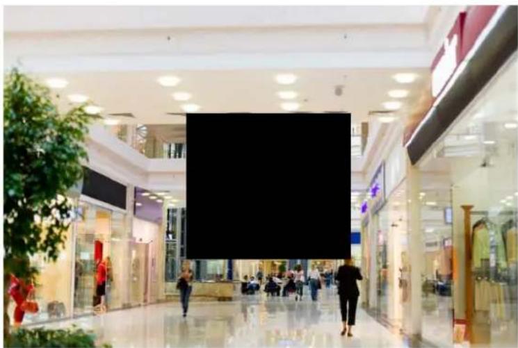
When privacy mask is configured, the intended area is blocked. The following shows an example.
- Set mask mode. You may select regular or irregular mode as needed. In irregular mode, when the PTZ camera rotates, the privacy mask varies with the shape of the masked object in the image.
natural_image
Interior view of a modern shopping mall with glass storefronts and shoppers (no visible text or signage)
NOTE!
• Mask mode is only available to certain models.
Audio and Video Configuration
Video Configuration
You can set video parameters that your camera supports and view the current status of BNC output. If available, you may also enable sub-stream and third stream as required.
NOTE!
- This function may vary with models. Only some camera models support the third stream. To determine if your camera supports this function, see the Web interface.
- After enabling the sub or third stream, modify the parameters as required. The parameters for the sub and third stream have the same meanings as that for the main stream.
1. Click Setup>Video & Audio>Video.
![Capture Mode 1080P@25 Main Stream Video Compression H.264 Resolution 1080P Frame Rate(fps) 25 Bit Rate(Kbps) 4096 [128~16384] Bitrate Type CBR Image Quality Quality Bit Rate I Frame Interval 50 [5 ~ 250] GOP IP Smoothing Clear Smooth SVC On Off U-Code Off BNC Output Mode PAL](/content/2026/05/958465/images/4643d7770aafeb6bfddef9f91d70d0641ce55a1a054ff0d152a0e684f63d847a.jpg)
- Modify the settings as required. The following table describes some major parameters.
| Parameter | Description |
| Video Compression | Three options: H.265, H.264 and MJPEG.Note:Image Quality cannot be set when Video Compression is set to H.265 or H.264. When set to MJPEG, only three frame rates are available: 1, 3 and 5; and Bit Rate, I Frame Interval, Smoothing and Smart Encoding cannot be set.The bit rate changes to the default when you change the setting between H.264 and H.265. The default bit rate for H.265 is half of that for H.264. |
| Frame Rate | Frame rate for encoding images. Unit: FPS (frame per second).Note:To ensure image quality, note that the frame rate should not be greater than the reciprocal of shutter speed. |
| Bitrate Type | CBR: Constant Bit Rate, which means that the camera transmits data at a constant data rate.VBR: Variable Bit Rate, which means that the camera adjusts the bit rate dynamically according to image quality. |
| Image Quality | WhenEncoding Modeis VBR, you can move the slider to adjust quality level for images.Moving the slider towardBit Ratedecreases the bit rate and may affect image quality.Moving the slider towardQualityincreases the bit rate and improves image quality. |
| I Frame Interval | Interval at which an I frame is encoded. Normally, a shorter I frame interval offers better image quality but consumes more bandwidth. |
| GOP | Group Of Pictures in MPEG video encoding. This parameter specifies the order in which intra-frames (I frame) and inter-frames are arranged. |
| SVC | SVC (Scalable Video Coding) can reduce storage without compromising playback quality. |
| Smart Encoding | Basic Mode: The actual bit rate is around 3/4 of the set bit rate.Advanced Mode: The actual bit rate is around 1/2 of the set bit rate.Note:When Smart Encoding is enabled, video compression only supports H.264 and H.265. MJPEG is not supported.When Smart Encoding is enabled, the capture mode does not support frame rates higher than 30. |
| Smoothing | Set the extent of smoothing. Choosing Clear means disabling Smoothing. Moving the slider toward Smooth increases the level of smoothing but will affect image quality.Note:In a poor network environment, you can enable smoothing to get more fluent video. |
| BNC Output | BNC output supports NTSC and PAL. |
3. Click Save.
Audio Configuration
Audio configuration means setting audio encoding parameters for your camera.

NOTE!
This function is not supported by some models. Please see the actual model for details.
1. Click Setup>Video & Audio>Audio.
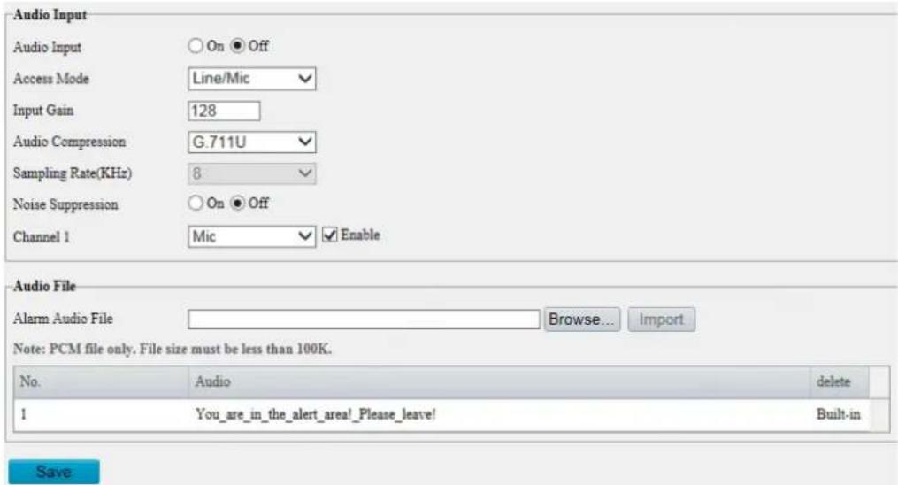
- Modify the settings as required. The following table describes some major parameters.
| Parameter | Description |
| Audio Input | No audio data will be encoded when Off is selected.Note:It is recommended to select Off if you do not need audio. This can improve device performance to some extent. |
| Access Mode | Currently only Line/Mic.Note:This function is not available to devices with two audio output channels. |
| Audio Compression | Two options: G.711U, G.711A.G.711U and G.711A support 8K sampling rate only. |
| Input Gain | Audio signal amplification for sampling. The greater the gain, the greater amplification. |
| Noise Suppression | Used to reduce noise in images. To enable noise suppression, select On. |
| Channel | Audio output channel. To enable audio output, select Enable.Note:Only some camera models support two channels. |
| Audio File | Import custom audio files.Note:Only PCM audio files are allowed, and the max size of a PCM file is 100K. |
3. Click Save.
Snapshot
1. Click Setup>Video & Audio>Snapshot.
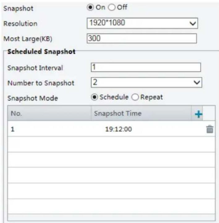
- Select On, and then set resolution, most large and schedule as needed. Some parameters are described in the table below.
| Parameter | Description |
| Snapshot Interval | Interval between two snapshots. For example, with Snapshot Interval set to 1 and Number of Snapshot set to 2, the camera will take 2 snapshots (take one first and then take another after 1 second). |
| Number to Snapshot | Currently 1, 2, and 3 snapshots are allowed. |
| Snapshot Mode | Schedule: You need to set a snapshot time, e.g., 19:12:00, which means the camera takes a snapshot at 19:12:00.Repeat: Allows you to set an interval(unit: sec). For example, according to the settings shown in the figure above, 60 seconds must elapse before the camera takes another two snapshots. |
3. Click Save.
ROI
When Region of Interest (ROI) is enabled, the system ensures image quality for ROI first if the bit rate is insufficient.

NOTE!
This function is not supported by some models. Please see the actual model for details.
- Click Setup>Video & Audio>ROI.
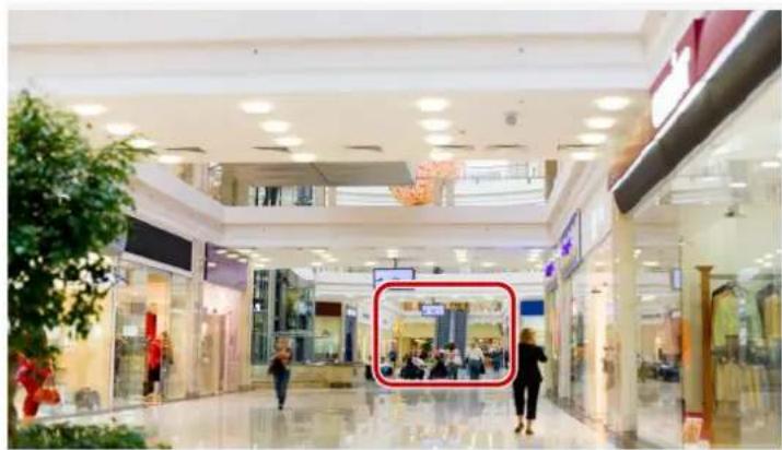
natural_image
Interior view of a modern shopping mall with visible store windows and shoppers (no signage or readable text)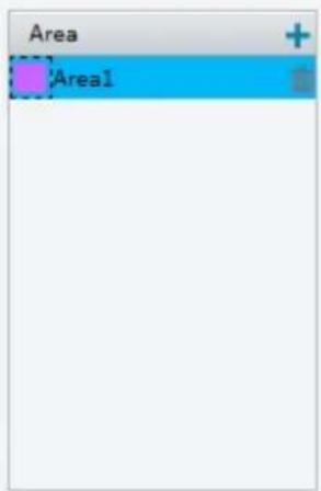
- Click +, and then drag the mouse to cover the intended part of the images. To delete, select the area and then click 📄
Media Stream Configuration
Media Stream
You can display the established media streams from a camera. You may also set the camera so it transmits code streams by the UDP or TCP protocol to a specified IP address and port number. The settings can be saved and take effect after the camera is restarted.
NOTE!
• This function is not supported by some models. Please see the actual model for details.
- Choosing a transport protocol based on your actual needs and network performance. Generally speaking, TCP enables better image quality than UDP but also causes higher latency.
1. Click Setup>Video & Audio>Media Stream.
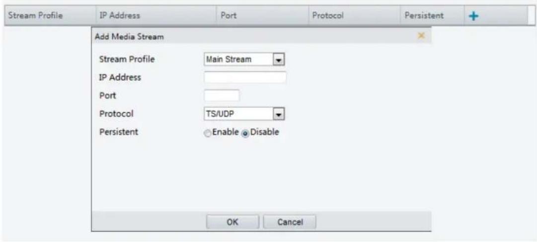
- Click +, select a stream type, and then set the IP address and port number of the unicast or multicast group for the decoding device that receives audio and video streams from the camera.
If you want the device to establish the media stream that has been configured before automatically after the restart, select Yes for Persistent.
- To delete a stream, click .
- Click Submit to complete the operations.
RTSP Multicast Address
After an RTSP multicast address is configured, the third-party player can request the RTSP multicast media stream from the camera through the RTP protocol.
1. Click Setup>Video & Audio>Media Stream>RTSP Multicast Address.
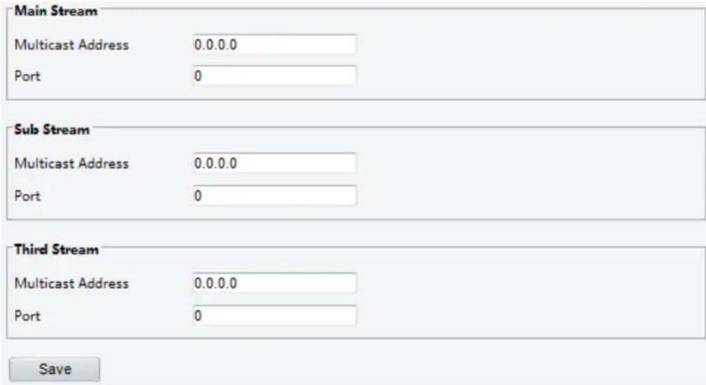
For some camera models, the page is displayed as follows.
| Main Stream | |
| Multicast Address | 0.0.0.0 |
| Port | 0 |
| Sub Stream | |
| Multicast Address | 0.0.0.0 |
| Port | 0 |
| Third Stream | |
| Multicast Address | 0.0.0.0 |
| Port | 0 |
| Multicast Address | 0.0.0.0 |
| Port | 0 |
| Multicast Address | 0.0.0.0 |
| Port | 0 |
| Multicast Address | 0.0.0.0 |
| Port | 0 |
-
Set the multicast address (224.0.0.0 to 239.255.255.255) and port number (0 to 65535).
-
Click Save.
Intelligent Alarm Configuration
You can configure intelligent monitoring to count people and monitor moving objects. Intelligent monitoring includes people counting, intrusion detection, and auto tracking.
The supported functions may vary with camera model.
Smart
Click Setup>Intelligent>Smart.
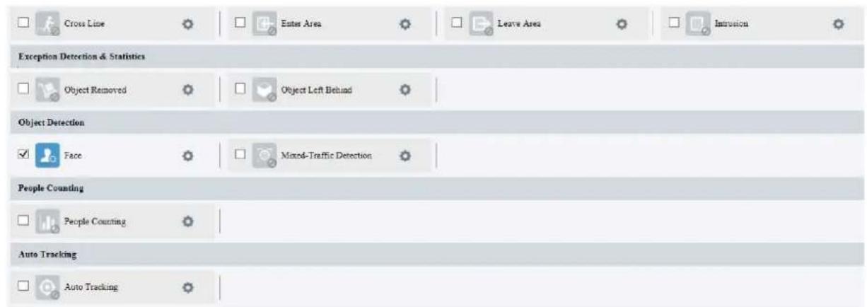
For some camera models, the page is displayed as follows.
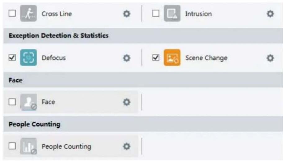
Cross Line Detection
Cross line detection detects objects that cross a virtual line in live video and triggers alarm when such an event is detected.

NOTE!
• Only some camera models support this function.
- The supported alarm triggering and arming schedule may vary with camera model. Please see the actual Web interface for details.
• The camera takes the snapshot and sends the snapshot to the back end.
- Click Setup >Intelligent>Smart. Choose Cross Line and then click
![Cross Line Detection Rule Settings Trigger Actions Plan Detection Rule Rule1 Rule1 Trigger Direction A<->B Sensitivity 50 Level High Snapshot Object Motor Vehicle Non-Motor Vehicle Pedestrian Filter Type Motor Vehiclo Max. Size 3839 X 2159 Min. Size 40 X 40 [None] Save](/content/2026/05/958465/images/6b37b1fb2a96582f979b4eb176023e5c2c17fcde2dd02b10e6d250b44f049286.jpg)
-
Select Cross Line Detection.
-
In the Detection Rule area, click + to add a new detection area. To delete a detection area, click 🔒.
-
On the small preview window, drag the line to the intended position and set the detection range.
-
Set the direction and sensitivity for the camera to decide whether to report a cross line detection alarm.
-
Set the priority of detection to judge the trigger sequence when detection rules are triggered at the same time.
-
Set snapshot object type to judge whether to snap small pictures
-
Set object filter type and size, alarm-triggered actions and arming schedule as required.
-
Set the alarm-triggered actions and arming schedule as required. For the detailed steps, see the descriptions of alarm-triggered actions in Common Alarm Configuration.
-
Click Save.
Enter Area
Enter Area detection detects objects that enter a specified area, and triggers alarm when such an event is detected.

NOTE!
• Only some camera models support this function.
- The supported alarm triggering and arming schedule may vary with camera model. Please see the actual Web interface for details.
• The camera takes the snapshot and sends the snapshot to the back end.
- Click Setup > Intelligent > Smart. Choose Enter Area, and then click ⚙️.
![Enter Area Detection Rule Settings Trigger Actions Plan Detection Rule Rule1 Rule1 Sensitivity 50 Level High Snapshot Object ✓ Motor Vehicle ✓ Non-Motor Vehicle ✓ Pedestrian Filter Type Motor Vehicle Max. Size 3829 X 2150 Min. Size 40 X 40 [None]](/content/2026/05/958465/images/0516fc7809ec872cb462342d748c706093642e968a058d36b6a2ebd67a5314d6.jpg)
- Select Enter Area Detection.
- In Rule Settings area, click + to add a new detection area. To delete a detection area, click 📄.
- Drag the borders of the box to set the intended position and range.
- Set detection sensitivity for the camera to decide whether to report an alarm.
-
Set the priority of detection to judge the trigger sequence when detection rules are triggered at the same time.
-
Set snapshot object type to judge whether to snap small pictures.
-
Set object filter type and size, alarm-triggered actions and arming schedule as required.
-
Set the alarm-triggered actions and arming schedule as required. For the detailed steps, see the descriptions of alarm-triggered actions in Common Alarm Configuration.
-
Click Save.
Leave Area
Leave Area detection detects objects that leave a specified area, and triggers alarm when such an event is detected.

NOTE!
• Only some camera models support this function.
- The supported alarm triggering and arming schedule may vary with camera model. Please see the actual Web interface for details.
• The camera takes the snapshot and sends the snapshot to the back end.
- Click Setup > Intelligent > Smart. Choose Leave Area, and then click 🔗.
![Leave Area Detection Rule Settings Trigger Actions Plan Detection Rule Rule1 Rule1 Sensitivity 50 Level High Snapshot Object ☑Motor Vehicle ☑Non-Motor Vehicle ☑Pedestrian Filter Type Motor Vehicle Max. Size 3839 X 2159 Min. Size 40 X 40 [None]](/content/2026/05/958465/images/ad3ef4321de14d4e1b496945d54276c68217b3821fabfcaa10cfc5403215d207.jpg)
-
Select Leave Area Detection.
-
In Rule Settings area, click + to add a new detection area. To delete a detection area, click 📄.
-
Drag the borders of the box to set the intended position and range.
-
Set detection sensitivity for the camera to decide whether to report an alarm.
-
Set the priority of detection to judge the trigger sequence when detection rules are triggered at the same time.
-
Set snapshot object type to judge whether to snap small pictures.
-
Set object filter type and size, alarm-triggered actions and arming schedule as required.
-
Set the alarm-triggered actions and arming schedule as required. For the detailed steps, see the descriptions of alarm-triggered actions in Common Alarm Configuration.
-
Click Save.
Intrusion Detection
Intrusion detection detects objects that enter a specified area in live video and triggers alarm when such an event is detected.

NOTE!
• Only some camera models support this function.
- The supported alarm triggering and arming schedule may vary with camera model. Please see the actual Web interface for details.
• The camera takes the snapshot and sends the snapshot to the back end.
1. Click Setup >Intelligent>Smart. Choose Intrusion and then click
![Intrusion Detection Rule Settings Trigger Actions Plan Detection Rule Rule1 Rule1 Time Threshold(x) 1 Sensitivity 50 Level High Snapshot Object ☑ Motor Vehicle ☑ Non-Motor Vehicle ☑ Pedestrian Filter Type Motor Vehicle □ Max. Size 3839 X 2159 □ Min. Size 40 X 40 [None] Save](/content/2026/05/958465/images/445b579c87ead2611675a0b6e65ba936c0c485df4e75e095dffe336dd2b851db.jpg)
2. Select Intrusion Detection.
- In the Detection Rule area, click + to add a new detection area. To delete a detection area, click ☑.
- Drag the borders of the box to set the intended position and range.
-
Set time threshold, sensitivity for the camera to decide whether to report an intrusion detection alarm.
-
Time Threshold: The minimum length of time that the intruder stays in the detection area before an alarm will be reported.
- Sensitivity: Sensitivity of detection. A greater value means higher detection sensitivity.
- Set the priority of detection to judge the trigger sequence when detection rules are triggered at the same time.
- Set snapshot object type to judge whether to take small pictures
- Set object filter type and size, alarm-triggered actions and arming schedule as required. Set the alarm-triggered actions and arming schedule as required. For the detailed steps, see the descriptions of alarm-triggered actions in Common Alarm Configuration.
- Click Save.
Object Moving
Detect objects left behind in the specified area and trigger alarms.
- Click Setup >Intelligent>Smart. Choose Object Moving and then click

![Enable Object Removed Detection Rule Settings Trigger Actions Plan Detection Rule [Rule] Rule1 Time Threshold(s) 5 Sensitivity 50 [None] Save](/content/2026/05/958465/images/5181998426ec8c15eb6e295189cb2817c5f5f240c219291930ebbe415d562382.jpg)
- Select Enable Object Moving Detection.
- In the Detection Rule area, click + to add a detection area. To delete, click 📄.
- Drag the box to set the position and effective range.
- Set time threshold and sensitivity to decide whether to report an intrusion detection alarm.
• Time threshold: Minimum duration an object is detected in the specified area to trigger an alarm.
- Sensitivity: The greater the number, the higher the sensitivity. An alarm is reported if an object is detected in the specified area for the specified length of time.
-
Set the alarm-triggered actions and arming schedule as required. For the detailed steps, see the descriptions of alarm-triggered actions in Common Alarm Configuration.
-
Click Save.
Object Left
Detect objects left behind in the specified area and trigger alarms.
- Click Setup>Intelligent>Smart. Choose Object Left and then click
![Enable Object Left Behind Detection Rule Settings Trigger Actions Plan Detection Rule Rule1 Rule1 Time Threshold(s) 10 Sensitivity 50 [None] Save](/content/2026/05/958465/images/ff6b65dd1c518e9aa81c14fb84ced893dbdb871384da115130b041cfefe54a87.jpg)
-
Select Enable Object Left Detection.
-
In the Detection Rule area, click + to add a detection area. To delete, click 📄.
- Drag the box to set the position and effective range.
- Set time threshold and sensitivity to decide whether to report an intrusion detection alarm.
• Time threshold: Minimum duration an object is detected in the specified area to trigger an alarm.
- Sensitivity: The greater the number, the higher the sensitivity. An alarm is reported if an object is detected in the specified area for the specified length of time.
6. Set the alarm-triggered actions and arming schedule as required. For the detailed steps, see the descriptions of alarm-triggered actions in Common Alarm Configuration.
7. Click Save.
Mixed -Traffic Detection
Mixed-traffic detection detects motor vehicles, non-motor vehicles, and pedestrians in configured area.

NOTE!
- Only some camera models support this function, and the actual interface may vary.
-
The supported alarm triggering and arming schedule may vary with camera model. Please see the actual Web interface for details.
• The camera takes the snapshot and sends the snapshot to the back end. -
Click Setup > Intelligent > Smart. Choose Mixed-Traffic Detection, and then click 🔒.
![Enable Mixed-Traffic Detection Rule Settings Trigger Actions Plan Snapshot Configuration Snapshot Area ● Full Screen ○ Specified Area Snapshot Sensitivity 50 Snapshot Object ✓ Motor Vehicle ✓ Non-Motor Vehicle ✓ Pedestrian Filter by Object Size(px) Filter Type Motor Vehicle Max. Size:3840 X 2160 Min. Size:40 X 40 [None] Save](/content/2026/05/958465/images/39524dca2d0e26b41cd2053d20aa500a726e5632a9acd4bd9816da350d850828.jpg)
- Choose Full Screen or Specified Area as detection area.
- Set snapshot sensitivity. The greater the value, the higher the sensitivity.
- Set snapshot object type to judge whether to snap small pictures.
- Set object filter type and size, alarm-triggered actions and arming schedule as required.
- Set the alarm-triggered actions and arming schedule as required. For the detailed steps, see the descriptions of alarm-triggered actions in Common Alarm Configuration.
- Click Save.
Face
Face detection detects faces in the configured area.

NOTE!
- Only some camera models support this function, and the actual interface may vary.
- The supported alarm triggering and arming schedule may vary with camera model. Please see the actual Web interface for details.
-
The camera takes the snapshot and sends the snapshot to the back end, which will compare the data with that in the database.
-
Click Setup > Intelligent > Smart. Choose Face, and then click ⚙️.
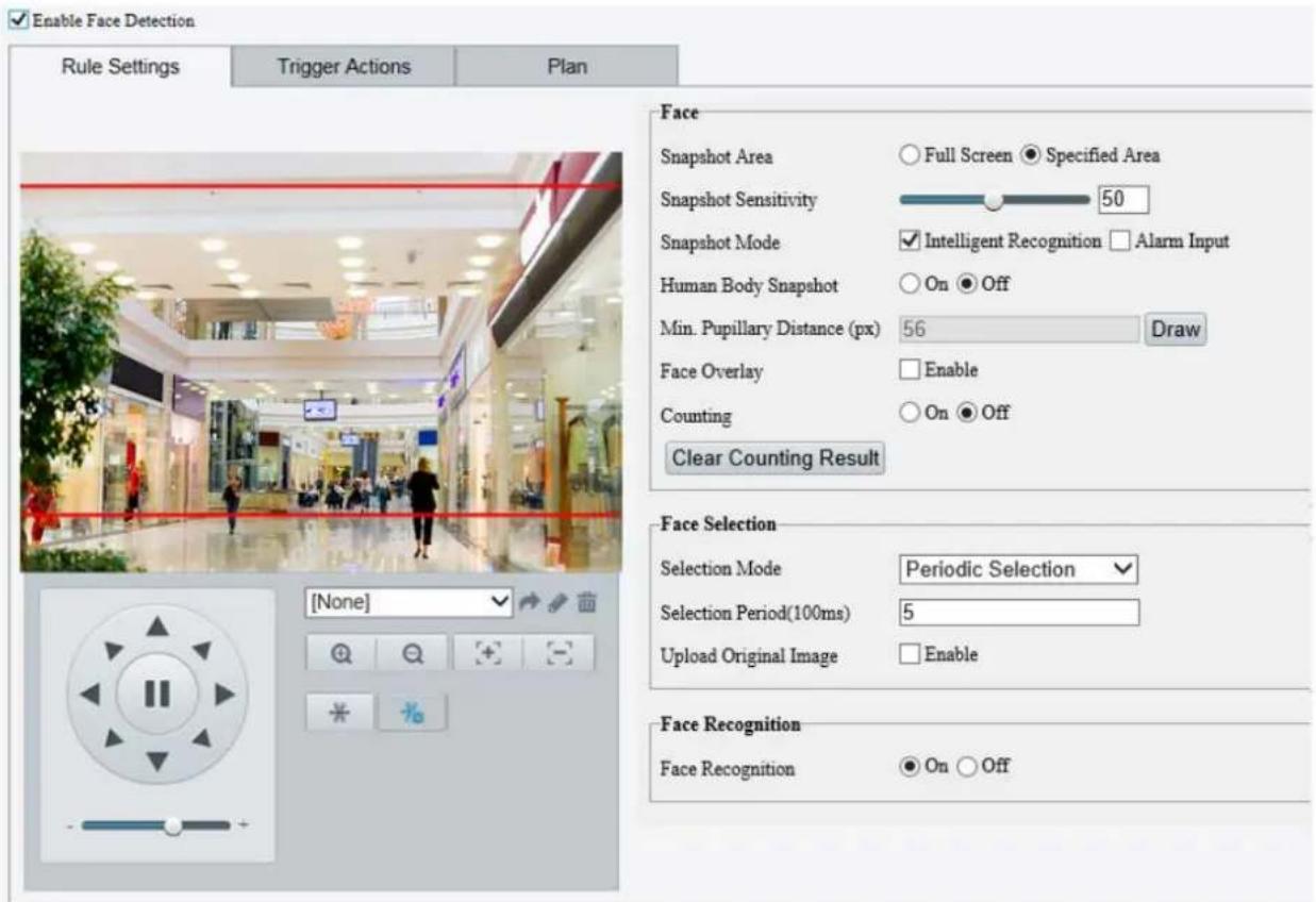
- Choose Full Screen or Specified Area as detection area.
- Set snapshot sensitivity. The greater the value, the higher the sensitivity.
- Set snapshot mode. In Intelligent Recognition, the camera detects and snapshots the object automatically.
- To enable snapshot of human body in the detection area, enable Human Body Snapshot.
- Set face counting direction. The counting results including people left and people entered statistics appear on live view. You need to select People Counting in OSD settings. Refer to "OSD Setting" Set OSD. for details.

NOTE!
• If Counting is disabled, counting direction setting will not show.
• After enabling Counting, select Enter or Leave according to the direction of your camera.
• The camera can send the counting statistics to managing platform.
- Set minimum pupillary distance. Click Draw and then draw in the left live view window.
- Enable face overlay, then a box will be added to the detected faces in the snapshot.
- Click Clear Counting Result to clear statistics.
- Configure face selection as required. The following table describes some major parameters:
| Item | Description |
| Selection Mode | Effect Priority: The camera selects snapshots with best image quality from the captured. You can set the number of photos to select.Speed Priority: The camera selects the optimal snapshots from the moment that the face is detected tillSelection Timeoutis up. You can set the number of photos to select.Periodic Selection: The camera selects a snapshot in every selection period. For example, ifSelection Periodis set to 500ms, the camareselects a face snapshot every 500ms, and ifUpload Original Imageis selected, both the original snapshot containing the face and the face cutout will be uploaded. |
-
Set the alarm-triggered actions and arming schedule as required. For the detailed steps, see the descriptions of alarm-triggered actions in Common Alarm Configuration.
-
Click Save.
Face Picture Comparison
The camera compares the captured faces with the face pictures in face library and reports comparison results.

NOTE!
- Only some models support this function, and the actual Web interface may vary.
-
The supported actions to trigger and arming schedule may vary with camera model. Please see the actual Web interface for details.
• Face picture comparison and human body snapshot cannot be enabled at the same time. -
Click Smart > Intelligent > Smart, choose Face, and click ☐. Enable Face Detection, then enable Face Recognition.
- Add face library.
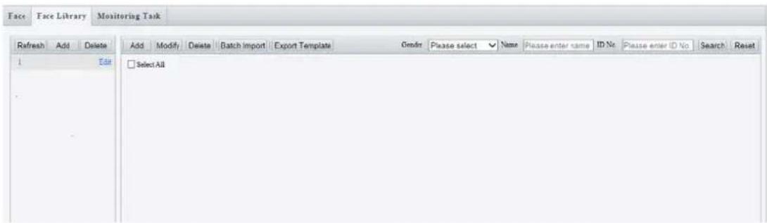
a. Create face library: Click Add, and set library name.
b. Add face data:
| Add Mode | Description | |
| Add a single piece of face data | Click Add, and enter personal information including name, gender, and date of birth. | |
 | ||
| Batch import | Import a CSV file containing face data to add multiple pieces of data. Click Batch Import, select the file to import, and click Upload. |
| Batch ImportFile PathBrowse...UploadMake sure the file to import complies with the template.Up to 5000 faces can be imported at a time. Please import separately if the total number exceeds this limit. |
3. Add monitoring task.
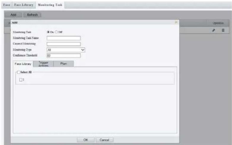
- Click Add, then set monitoring task name and cause of monitoring based on your needs.
| Monitoring Type | Description |
| Match Alarm | If the similarity between a captured face and a face in the monitored library reaches the confidence threshold, the device reports a match alarm and perform the set triggered actions. |
| Not Match Alarm | If the similarity between a captured face and a face in the monitored library fails to reach the confidence threshold, the device reports a not match alarm and perform the set triggered actions. |
| Alarm | The device reports an alarm and perform the set triggered actions at a face detected whether the confidence threshold is reached. |
• To edit a monitoring task, click

NOTE!
The higher the confidence threshold, the higher the sensitivity.
- Select the face library to monitor and set the actions to trigger and arming plan.
Human body detection detects the human body appearing in configured area.

NOTE!
• Only some models support this function.
- The supported actions to trigger and arming schedule may vary with camera model. Please see the actual Web interface for details.
- Click Setup > Intelligent > Smart, choose Human Body Detection, and click 🔒.
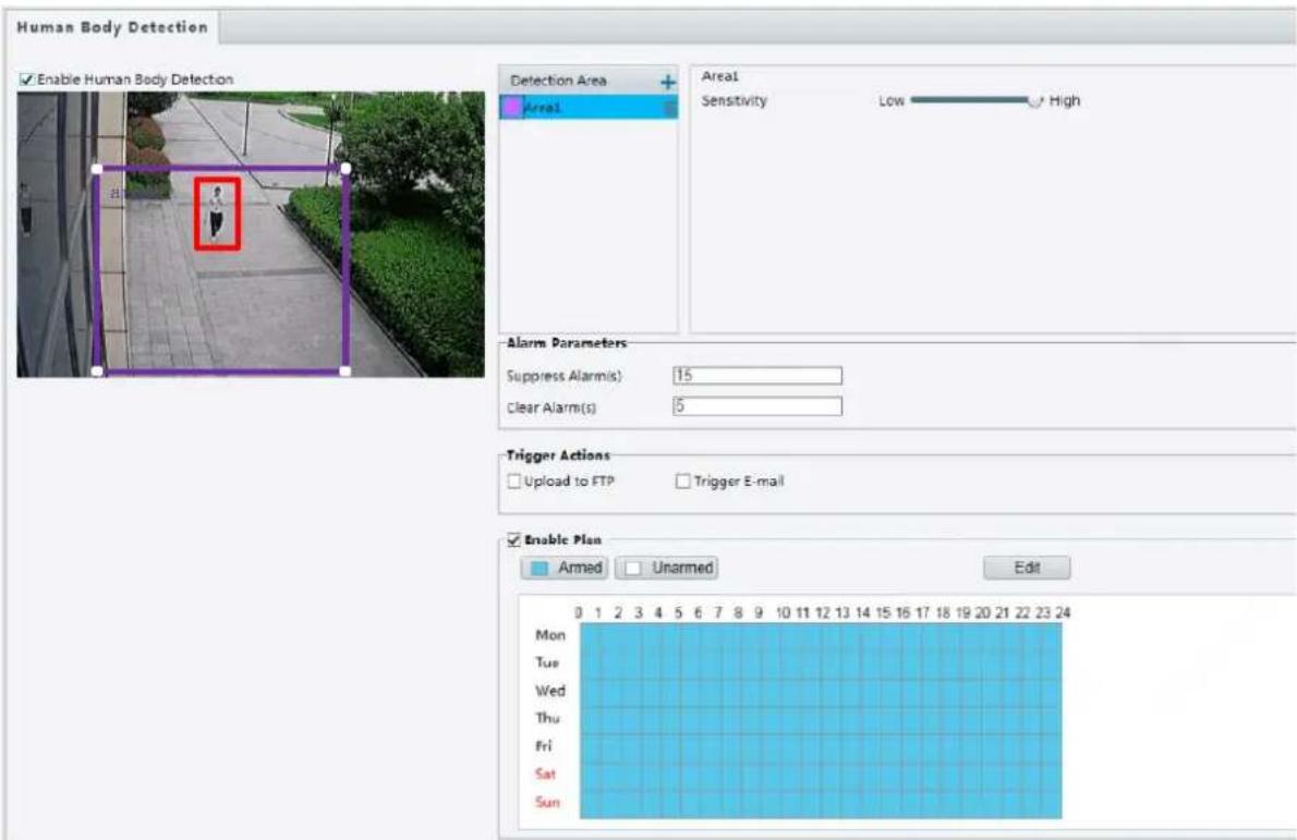
-
Select the checkbox of Enable Human Body Detection.
-
In the Detection Area, click + to add a snapshot area. To delete an area, click 📄.
- Drag your mouse in the live view window to set a detection area.
- Set detection sensitivity for the camera to decide whether to report a human body detection alarm. The higher the sensitivity, the more likely a human body detection alarm will be reported.
- Set alarm parameters.
- Suppress Alarm(s): After an alarm is triggered, the same alarm will not be reported within the set time.
- Clear Alarm(s): After alarm suppression, if no same alarm is triggered within the set time, an alarm being cleared will be reported.
-
Set the actions to trigger and arming schedule. For the detailed steps, see the descriptions of alarm-triggered actions in Configuring Motion Detection Alarm.
-
Click Save.

NOTE!
• Only some camera models support this function.
- The supported alarm triggering and arming schedule may vary with camera model. Please see the actual Web interface for details.
1. Click Setup >Intelligent>Smart. Choose People Counting and then click

![Enable Passenger Flow Detection Rule Settings Plan Counting Type Total Detection Mode Indoor Reset Counter at 00:00:00 Sensitivity 50 Draw Detection Area Draw Entrance Direction Filter by Object Size (Width X Height)(px) Max. Size 439 X 439 Min. Size 240 X 240 [None] Tip: Please set the detection area between the two red lines to achieve the best detection effect. Clear Counting Result Save](/content/2026/05/958465/images/e6d2708219882206ec0d1ce7fe48d1d2e72584692564e479c329ef2f81f76654.jpg)
- Select Enable Passenger Flow Detection. Select a detection mode, set report interval and sensitivity.
- Click Draw Detection Area, and then draw a detection area on the preview window on the left, e.g., a square.
- Click Draw Entrance Direction, and then draw the direction on the preview window on the left. The direction is usually vertical or sloping.
-
Set Max. Size and Min. Size under Filter by Object Size. Only objects within the size range will be counted; others will be filtered and not counted. The maximum width or height must be greater than the minimum width or height.
-
Set the alarm-triggered actions and arming schedule as required. For the detailed steps, see the descriptions of alarm-triggered actions in Common Alarm Configuration.
-
To reset counting results, click Clear Counting Result.
-
Click Save.
Auto Tracking
The camera automatically tracks an object that triggers the rule.

NOTE!
• Only some camera models support this function.
- The supported alarm triggering and arming schedule may vary with camera model. Please see the actual Web interface for details.
- Click Setup >Intelligent>Smart. Choose Auto Tracking and then click
![Enable Auto Tracking Rule Settings Parameters Continuously Track Max Tracking Time(s) 30 Zoom Auto [None] Save](/content/2026/05/958465/images/36437d6695c6935f38016a7819e0d114b20e512fedd081e5be323974e8e83fa2.jpg)
- Set tracking timeout (unit: sec) and zoom ratio.
- With Continuously Track selected, the camera continuously tracks an object that triggers the rule until target cannot be detected.
- Click Save.
Heat Map
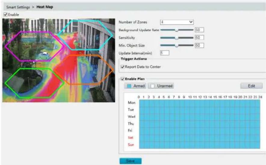
The heat map uses different colors to display visitor traffic patterns. A dark color, red, for example, indicates higher traffic density.
- Click Setup>Intelligent>Smart. Choose Heat Map and then click
-
Select Enable.
-
Set Background Update Rate. The greater the value, the quicker the image refreshes.
-
Set Sensitivity. The greater the value, the more likely that small objects will be detected.
-
Set Min. Object Size. The greater the value, the more small objects will be ignored during detection.
-
Set update interval for reporting statistics to the platform.
-
Set the alarm-triggered actions and arming schedule as required. For the detailed steps, see the descriptions of alarm-triggered actions in Common Alarm Configuration.
-
Click Save.
Defocus Detection

NOTE!
• Only some camera models support this function.
- The supported alarm triggering and arming schedule may vary with camera model. Please see the actual Web interface for details.
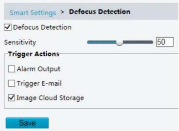
Use defocus detection to detect defocus of the camera and to report an alarm when such an event is detected.
- Click Setup >Intelligent>Smart. Choose Defocus and then click
-
Select Defocus Detection.
-
Set the alarm-triggered actions and arming schedule as required. For the detailed steps, see the descriptions of alarm-triggered actions in Common Alarm Configuration.
-
Click Save.
Scene Change Detection

NOTE!
• Only some camera models support this function.
- The supported alarm triggering and arming schedule may vary with camera model. Please see the actual Web interface for details.
Use scene change detection to detect the change of surveillance environment caused by external factors such as intentional rotation of the camera, and to report an alarm when such an event is detected.
- Click Setup >Intelligent>Smart. Choose Scene Change and then click
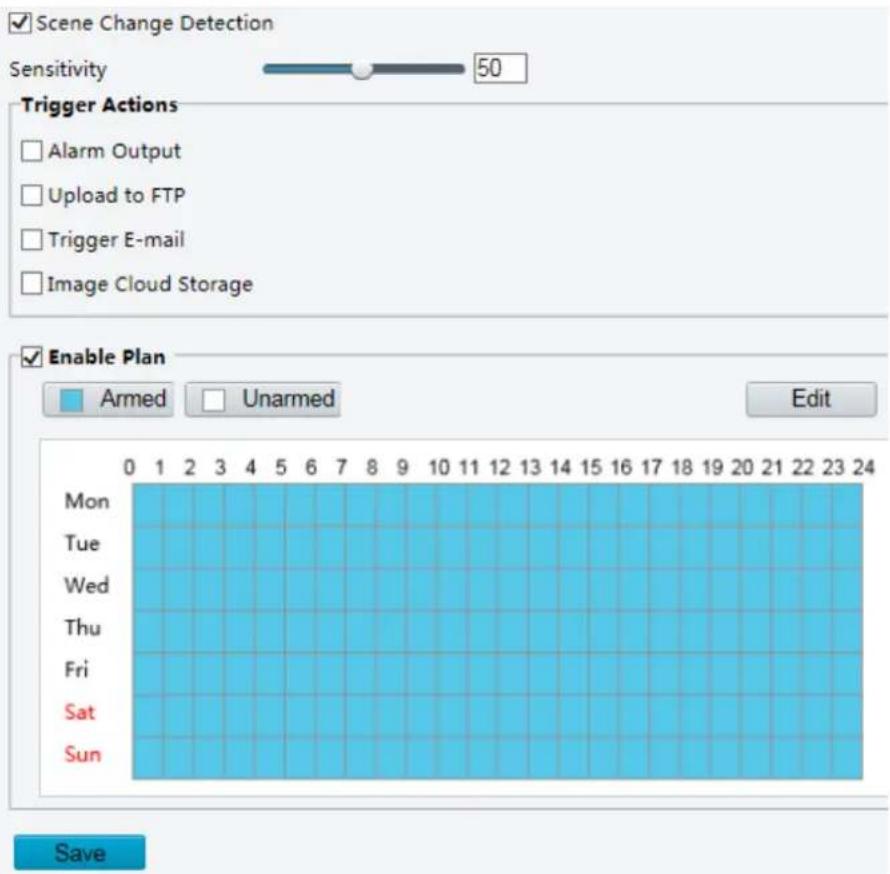
- Select Scene Change Detection.
- Set detection sensitivity.
- Set the alarm-triggered actions and arming schedule as required. For the detailed steps, see the descriptions of alarm-triggered actions in Common Alarm Configuration.
- Click Save.
Advanced Settings
Advanced settings include snapshot clarity and detection mode for intelligent functions.
Photo parameters
Set clarity of snapshots.
-
Click Setup >Intelligent>Advanced Settings. Click Photo parameters tab.
-
Set the thumbnail image clarity.
- Click Save.

NOTE!
Please turn off the Face Detection before setting the photo parameter.

NOTE!
-
Only some camera models support advanced settings. Please see the actual Web interface for details.
• The default detection mode is Normal Mode. Set as required. -
Click Setup >Intelligent>Advanced Settings. Click Detection Parameters tab.
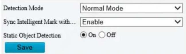
-
Choose a detection mode. Choose Filter Repeated Motion Mode to prevent repeated alarm reporting caused by repeated motion detected in the surveillance environment.
-
Click Save.
Master-Slave Linkage

NOTE!
• Only some camera models support this function.
- The supported linkage parameters, linkage mode and alarming schedule may vary with camera model. Please see the actual Web interface for details.
- Click Setup >Intelligent>Smart. Choose Master-Slave Linkage, click 🔒 and then select Linkage Parameter tab.
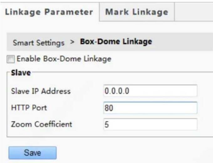
For some camera models, the page is displayed as follows.
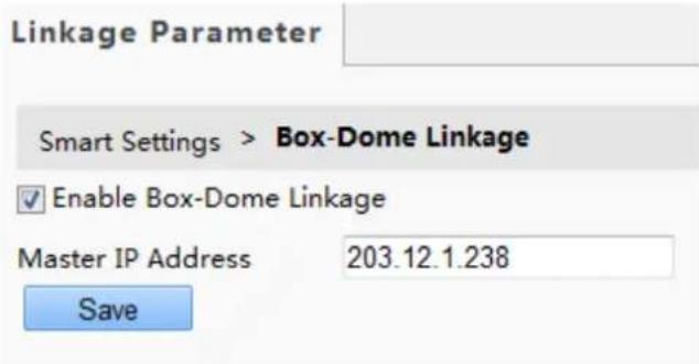
- Select Enable Box-Dome Linkage.
- Set master or slave IP address, HTTP port, and zoom coefficient.
- Click Save.
- Select Mark Linkage tab.
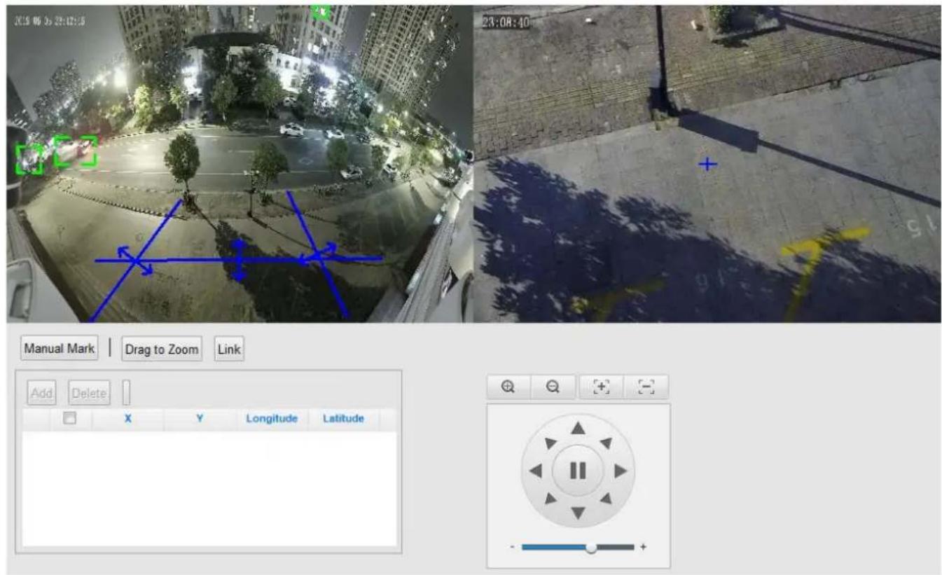
- Click Manual Mark, the following page will be displayed. The meaning of buttons:
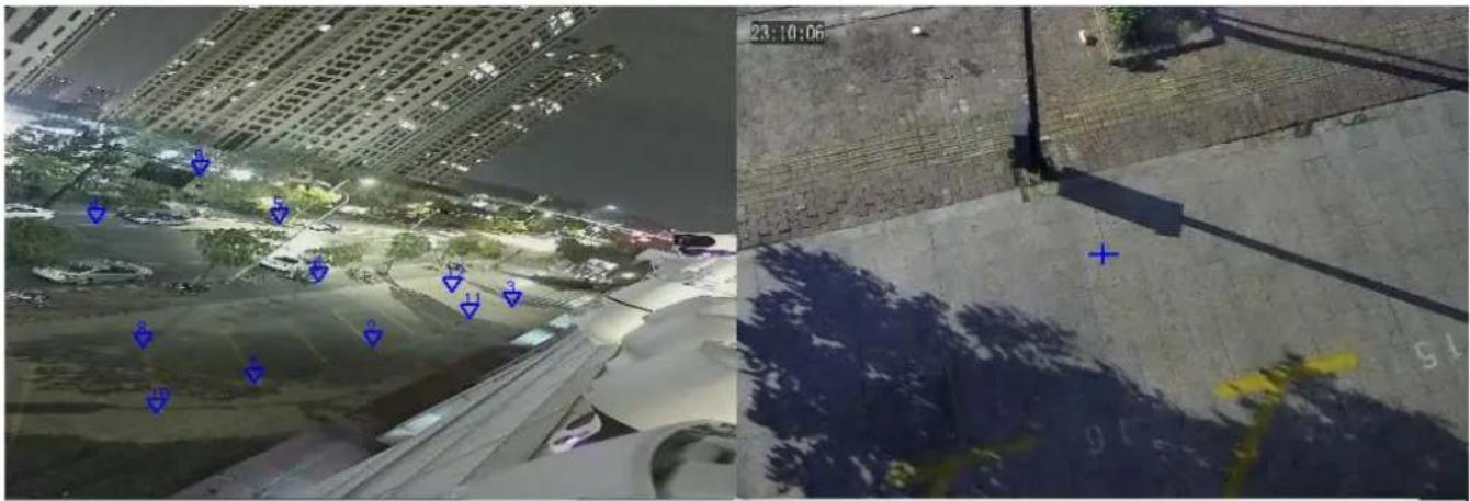
Previous Next End Marking The area automatically zooms in when you mark a point on the image (left); right-click to zoom out.
| Mark Parameters | |||||
| Add | Delete | Clear All | |||
| ☐ | X Coordinate | Y Coordinate | PTZ Longitude | PTZ Latitude | |
| 1 | ☐ | 1459 | 4067 | 18292 | 1854 |
| 2 | ☐ | 4479 | 6146 | 16794 | 2135 |
| 3 | ☐ | 5059 | 2852 | 15651 | 1939 |
| 4 | ☐ | 2172 | 6407 | 15661 | 2816 |
| 5 | ☐ | 3439 | 4940 | 17398 | 2093 |
| - | ☐ | 5102 | 5102 | 5102 | 5102 |
natural_image
Circular play button interface with directional arrows and a slider (no text or symbols)Previous/Next: Change marking scene when you finish marking operation in the current scene.
End Marking: End marking operation without saving.
Add/Delete: Add or delete marking point.
Clear All: Clear all the marking points on this page.
- Marking steps on a single marking page are as follows: Click Add, and then click on the left master camera image. A small white frame appears at your clicking, and the area automatically zooms in (as shown below). Click OK to confirm current marking point, or right-click to return to original image.
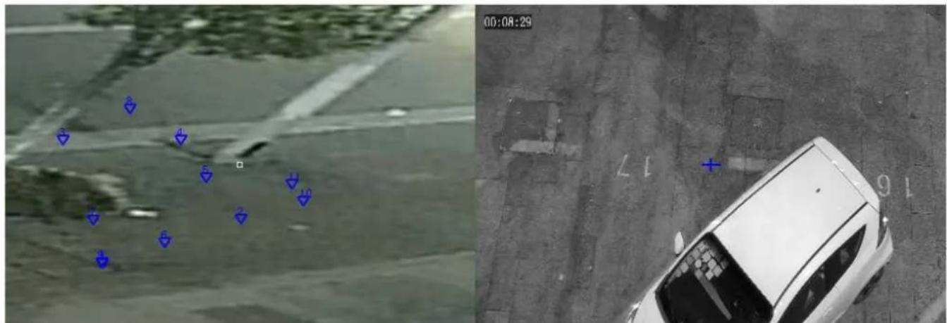
-
Turn the slave camera to the position where the marking point is. Set the magnification of the slave camera to the maximum and make the cross in the center of the slave camera image coincide with the marking point (the small white frame) in the master camera image. Click OK and Orient to link the marking points. Click Cancel to cancel the linked marking points.
-
Click a new position in the master camera image and repeat last step. You may need 5\~12 marking points depending on your needs. Click Finish and Next to turn to the next scene.
-
Click Apply after you finish all the marking configurations. For multi-sensor cameras, click the button after the marking configuration of four scenes is completed.
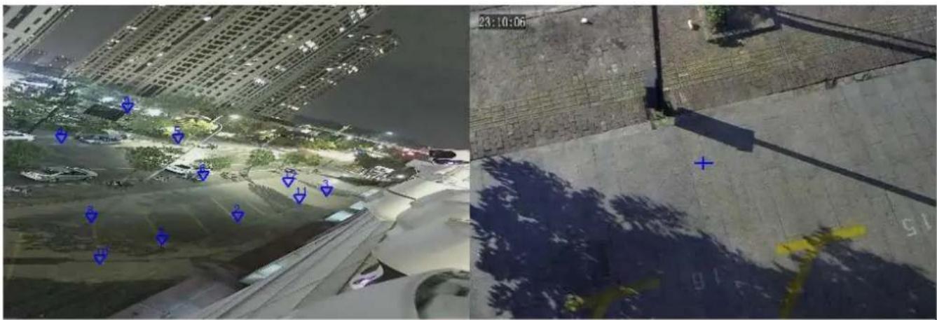
natural_image
Aerial night view of a coastal urban area with illuminated buildings and waterways, alongside a close-up of a paved road with blue markers (no readable text or symbols)Apply Previous Next End Marking The area automatically zooms in when you mark a point on the image (left); right-click to zoom out.
| Mark Parameters | |||||
| Add | Delete | Clear All | |||
| ☐ | X Coordinate | Y Coordinate | PTZ Longitude | PTZ Latitude | |
| 1 | ☐ | 2879 | 3205 | 34023 | -443 |
| 2 | ☐ | 5839 | 8205 | 35780 | 384 |
| 3 | ☐ | 5179 | 6528 | 5009 | 204 |
| 4 | ☐ | 3679 | 8852 | 7141 | 1321 |
| 5 | ☐ | 9539 | 3911 | 8604 | 998 |
natural_image
User interface panel with playback controls and a circular play button (no text or symbols)Attribute Collection

NOTE!
-
Attribute collection functions with other smart features.
• To display attributes in live view page, you need to enable Display Attribute in Local Parameters first.
• The interface may vary with model and smart function. Please see the actual interface for details. -
Click Setup > Intelligent > Smart Settings, and choose Attribute Collection.
- Select the attributes to collect under each attribute category.
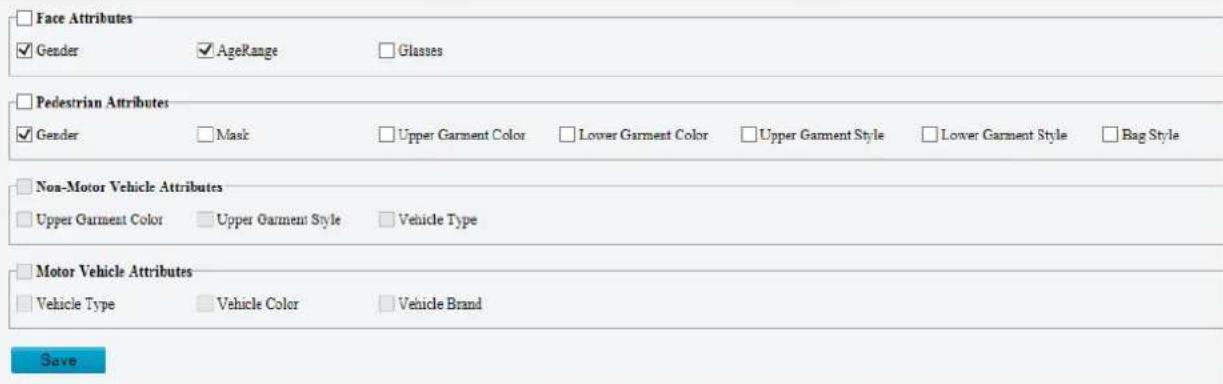
- Click Save.
Master-Slave Linkage Use master-slave linkage to link a master device and a slave device. The master device detects the target and the linked slave device tracks and captures the target.
NOTE!
• Only some camera models support this function.
- The supported linkage parameters, linkage mode and alarming schedule may vary with camera model. Please see the actual Web interface for details.
- Click Setup > Intelligent > Smart. Choose Master-Slave Linkage, click 🔒 and then select Linkage Parameter.
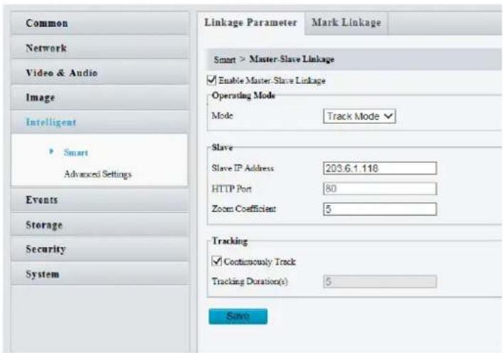
For some camera models, the page is displayed as follows.
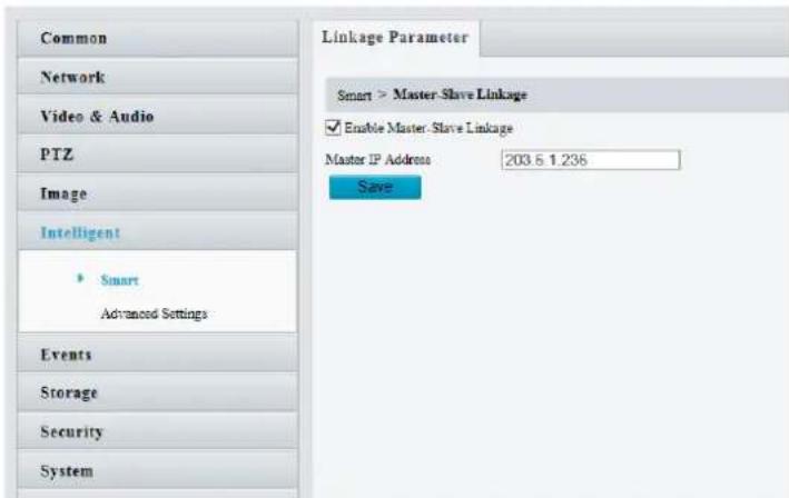
- Select Enable Box-Dome Linkage.
- Track Mode: The linked slave camera tracks the target that triggers the set rules, until timeout is up, or the target disappears.
- Set master or slave IP address and HTTP port.
- Zoom coefficient: the greater the coefficient, the greater the zoom of the slave device.
- Select Continuously Track and set tracking duration.
- Click Save.
- Click Mark Linkage.
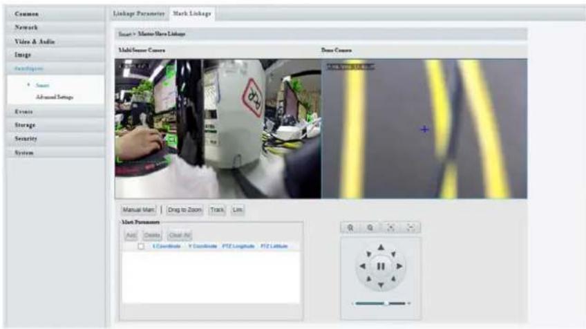
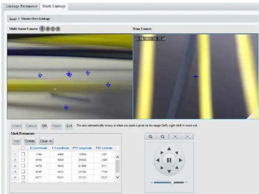
- Click Manual Mark, the following page will be displayed. The meaning of the buttons:
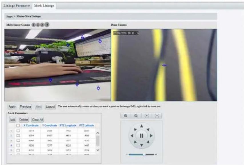
OK/Apply: After completing the marking of one scene, click OK or Apply to save and update the linkage between the master and slave camera.
Next: Change marking scene when you finish marking operation in the current scene.
Exit: Exit marking without saving.
Add: Add marking points.
Delete: Delete marking points.
Clear All: Clear all the marking points in current scene.
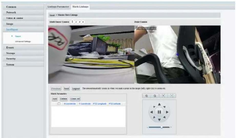
- Marking steps on a single scene: Click Add, click on the left master camera image. A small white frame appears at your clicking, and the area automatically zooms in (as shown below). Adjust the position of the marking point on the enlarged area. Right click to return to original image and select again. Click OK to confirm current marking point.
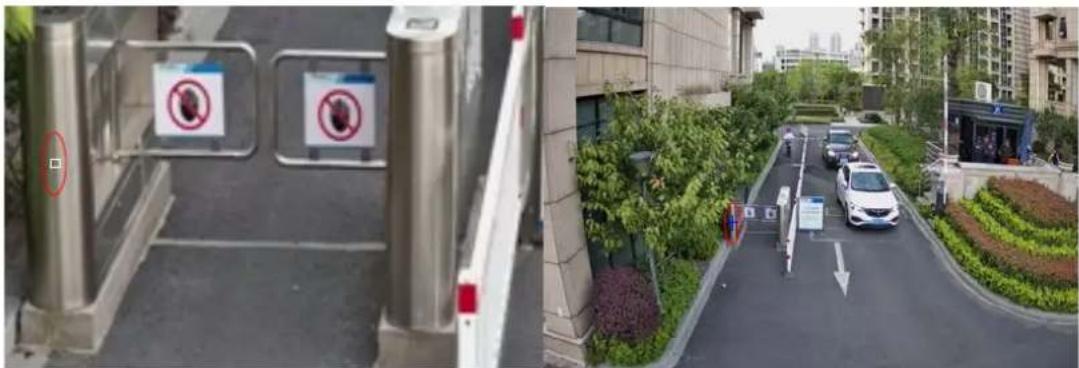
- Turn the slave camera to the position where the marking point is. Set the zoom of the slave camera to the maximum and adjust the cross in the center of the slave camera image coincide with the marking point (the small white frame) in the master camera image. Then click Orient.
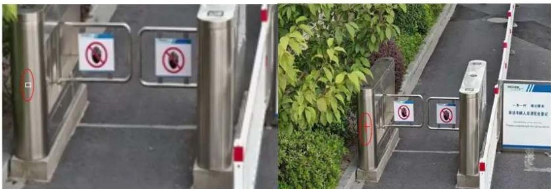
- Repeat the last two steps to add other marking points. You may need 5\~12 marking points depending on your needs. Click Finish after marking is completed. For some camera models, you need to complete the marking of several scenes.
Common Alarm Configuration
You can schedule alarm reporting and set actions that can be triggered by other devices so that alarms and the triggered actions can be handled in time.
Alarm reporting can be scheduled for motion detection alarm, alarm input, alarm output, tampering detection alarm, and audio detection alarm. The supported alarms may vary with device model. For the alarm types that your camera supports, see the Web interface.
The following table describes the major alarm-triggered actions and how to set a plan.
| Item | Description | |
| Alarm Output 1 | Select the check box. This setting is the alarm output interface linked to motion detection alarm.Note:When an alarm is reported, the camera triggers alarm output so as to trigger actions by a third-party device. | |
| Go to Preset | Select the check box and set the preset linked to motion detection alarm.Note:Make sure you have set presets. Otherwise, you cannot set this parameter. For details about how to set a preset, seeSetting Presets.When an alarm is reported, the PTZ camera automatically goes to the preset to capture video in the correct scene. | |
| Upload to FTP | WithUpload to FTPselected, the camera will automatically upload snapshots to the specified FTP server when an alarm is triggered.Note:Make sure you have completedFTPandSnapshotbefore using this function. | |
| Recording | WithRecordingselected, the camera will automatically record video when an alarm is triggered.Note:Please setPost-Record(s)on theStoragepage first. Post-Record(s)specifies how long recording continues after the end of an alarm. | |
| Alarm the Center | WithAlarm the Centerselected, the camera will sends alarm information to the central server when an alarm is triggered.Note:Please complete settings on theServerpage first. | |
| Upload Image (Original) | With Upload Image (Original) selected, The camera uploads the snapshot original image to the server or platform.Note:Make sure you have completed FTP and Snapshot before using this function. | |
| Upload Image (Object) | With Upload Image (Object) selected, The camera uploads the snapshot object image to the server or platform.Note:Make sure you have completed FTP and Snapshot before using this function. | |
| Attribute | WithAttribute Collectionselected, The camera uploads the attribute information to the server | |
| Collection | or platform. Note: Only some camera models support this function. Please set Attribute Collection on the Attribute Collection page first. | |
| Trigger Tracking | With Trigger Tracking selected, the camera starts auto tracking when an alarm is triggered. Note: Only some camera models support this function. Please set auto tracking on the Smart Settings page first. | |
| Trigger E-mail | With Trigger E-mail selected, the camera will automatically send snapshots to the specified E-mail address when an alarm is triggered. Note: Make sure you have completed E-Mail before using this function. | |
| Enable Plan | Select the check box and set the start and end times during which motion detection alarm is effective. You can directly drag the mouse to draw a plan and click Edit to edit time periods in the table. The time periods cannot overlap. The camera reports alarms during the specified period(s) only. You can select from Monday to Sunday and set four periods for each day. | |
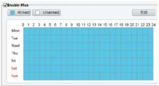 | 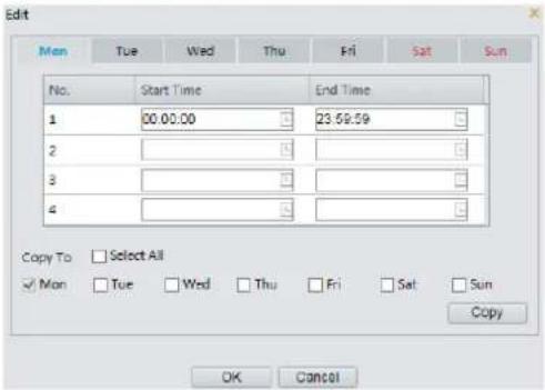 | |
| Drag the mouse to draw a plan | Edit time periods in the table | |
| Note: Plan drawing using a mouse is only supported by IE versions later than 8.0. After setting the plan for one day, you can apply the same settings to other days by clicking Copy and Paste. | ||
1. Click Save.
Configuring Motion Detection Alarm
Motion detection detects the object motion in a specified rectangular area during a period. You need to set a detection area, sensitivity of detection, object size, and history for the camera to decide whether to report a motion detection alarm when it detects motion.

NOTE!
• This function is not supported by some models. Please see the actual model for details.
• The alarm triggered actions may vary with models. Please see the actual Web interface for details.
Area Detection
- Click Setup > Events > Common Alarm > Motion Detection. Set Detection Mode to Area.
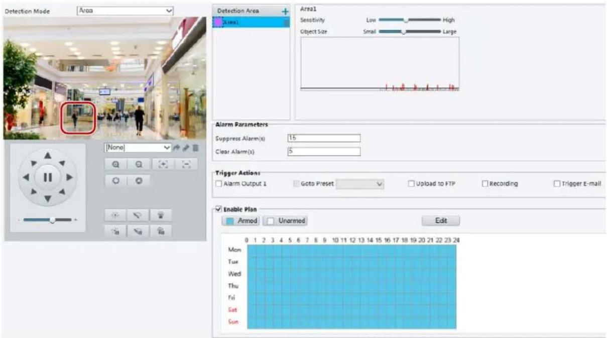
-
In the Detection Area, click + to add a new detection area. To delete a detection area, click 📄.
-
Click and drag the mouse to set a detection area.
-
Set the detection sensitivity, object size, and history for the camera to decide whether to report a motion detection alarm.
-
Moving the slider to the right increases detection sensitivity. When the extent of motion within the detection area exceeds the set object size, the camera reports an alarm.
- Object size specifies the minimum ratio of the object's size to the size of the total detection area before an alarm will be reported. That is to say, to detect motion of tiny objects, you need to draw a small box (detection area) in the actual motion area accordingly.
- Motion detection results are shown in real time. The red lines represent the raised motion detection alarms. The longer a line, the greater the extent of motion. The denser the lines, the greater the frequency of motion.
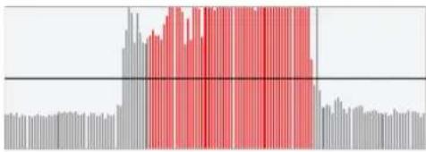
bar
| Category | Value | |---|---| | Bar 1 | 0.5 | | Bar 2 | 0.6 | | Bar 3 | 0.7 | | Bar 4 | 0.8 | | Bar 5 | 0.9 | | Bar 6 | 1.0 | | Bar 7 | 1.1 | | Bar 8 | 1.2 | | Bar 9 | 1.3 | | Bar 10 | 1.4 | | Bar 11 | 1.5 | | Bar 12 | 1.6 | | Bar 13 | 1.7 | | Bar 14 | 1.8 | | Bar 15 | 1.9 | | Bar 16 | 2.0 | | Bar 17 | 2.1 | | Bar 18 | 2.2 | | Bar 19 | 2.3 | | Bar 20 | 2.4 | | Bar 21 | 2.5 | | Bar 22 | 2.6 | | Bar 23 | 2.7 | | Bar 24 | 2.8 | | Bar 25 | 2.9 | | Bar 26 | 3.0 | | Bar 27 | 3.1 | | Bar 28 | 3.2 | | Bar 29 | 3.3 | | Bar 30 | 3.4 | | Bar 31 | 3.5 | | Bar 32 | 3.6 | | Bar 33 | 3.7 | | Bar 34 | 3.8 | | Bar 35 | 3.9 | | Bar 36 | 4.0 | | Bar 37 | 4.1 | | Bar 38 | 4.2 | | Bar 39 | 4.3 | | Bar 40 | 4.4 | | Bar 41 | 4.5 | | Bar 42 | 4.6 | | Bar 43 | 4.7 | | Bar 44 | 4.8 | | Bar 45 | 4.9 | | Bar 46 | 5.0 | | Bar 47 | 5.1 | | Bar 48 | 5.2 | | Bar 49 | 5.3 | | Bar 50 | 5.4 | | Bar 51 | 5.5 | | Bar 52 | 5.6 | | Bar 53 | 5.7 | | Bar 54 | 5.8 | | Bar 55 | 5.9 | | Bar 56 | 6.0 | | Bar 57 | 6.1 | | Bar 58 | 6.2 | | Bar 59 | 6.3 | | Bar 60 | 6.4 | | Bar 61 | 6.5 | | Bar 62 | 6.6 | | Bar 63 | 6.7 | | Bar 64 | 6.8 | | Bar 65 | 6.9 | | Bar 66 | 7.0 | | Bar 67 | 7.1 | | Bar 68 | 7.2 | | Bar 69 | 7.3 | | Bar 70 | 7.4 | | Bar 71 | 7.5 | | Bar 72 | 7.6 | | Bar 73 | 7.7 | | Bar 74 | 7.8 | | Bar 75 | 7.9 | | Bar 76 | 8.0 | | Bar 77 | 8.1 | | Bar 78 | 8.2 | | Bar 79 | 8.3 | | Bar 80 | 8.4 | | Bar 81 | 8.5 | | Bar 82 | 8.6 | | Bar 83 | 8.7 | | Bar 84 | 8.8 | | Bar 85 | 8.9 | | Bar 86 | 9.0 | | Bar 87 | 9.1 | | Bar 88 | 9.2 | | Bar 89 | 9.3 | | Bar 90 | 9.4 | | Bar 91 | 9.5 | | Bar 92 | 9.6 | | Bar 93 | 9.7 | | Bar 94 | 9.8 | | Bar 95 | 9.9 | | Bar 96 | 10.0 | | Bar 97 | -0.1 | | Bar 98 | -0.2 | | Bar 99 | -0.3 | | Bar100 | -0.4 |-
Set the alarm parameters.
-
Suppress Alarm(s): After an alarm is triggered, the same alarm will not be reported within the set time.
• Clear Alarm(s): After an alarm is triggered,
a. If the same alarm is not triggered within the set time, the alarm will be cleared, and the same alarm can be reported again.
b. If the same alarm is triggered within the set time, the alarm will not be cleared until the suppress alarm time expires. Then the same alarm can be reported again.
- Set actions to be triggered by motion detection alarm and the plan.
Grid Detection
1. Click Setup > Events > Motion Detection. Set Detection Mode to Grid.
![Detection Mode Grid Sensitivity Low High Alarm Parameters Suppress Alarm(s) 15 Clear Alarm(s) 5 Trigger Actions Alarm Output 1 Goto Preset 1[DOOR] Upload to FTP Recording Trigger E-mail Enable Plan Armed Unarmed Edit Mon Tue Wed Thu Fri Sat Sun](/content/2026/05/958465/images/c738406902056da0566213f94abc64b9d7218b6dd7b704c71b77f904652b6ec6.jpg)
- Detection area(s) can be irregular on the grid.
- Set detection sensitivity for the camera to decide whether to report a motion detection alarm (alarm visible on compatible NVR).
-
Set alarm parameters.
-
Suppress Alarm(s): After an alarm is triggered, the same alarm will not be reported within the set time.
• Clear Alarm(s): After an alarm is triggered,
a. If the same alarm is not triggered within the set time, the alarm will be cleared and the same alarm can be reported again.
b. If the same alarm is triggered within the set time, the alarm will not be cleared until the suppress alarm time expires. Then the same alarm can be reported again.
-
Set actions to be triggered by motion detection alarm and the plan. For the detailed steps, see the descriptions of alarm-triggered actions in Area Detection in Configuring Motion Detection Alarm.
-
Click Save.
Configuring Tampering Alarm
Configure tampering alarm so that the camera reports a tampering alarm when the lens is blocked for a certain length of time.

NOTE!
• This function is not supported by some models. Please see the actual model for details.
• The alarm triggered actions may vary with models. Please see the actual Web interface for details.
- Click Setup>Events>Common Alarm >Tampering Alarm.
![Tampering Alarm Sensitivity 50 Duration(s) 1 Trigger Actions Alarm Output 1 Goto Preset 1[DOOR] Upload to FTP Recording Trigger E-mail Enable Plan Armed Unarmed Edit Mon Tue Wed Thu Fri Sat Sun](/content/2026/05/958465/images/d94bad96aace42bb25edb1ec9050988a471e64235024240a36f1f7eb574cd204.jpg)
- Select On for Tampering Alarm.
- Set detection sensitivity and duration for the camera to decide whether to report a tampering alarm.
Sensitivity is divided into three levels: high-level, mid-level and low-level. Compared with mid-level sensitivity, the camera can detect blocking from a farther location when sensitivity is set to high. The camera reports an alarm when the lens is blocked for a specified length of time.
Tampering alarm is effective to the whole screen. To disable tampering alarm, clear the Tampering Alarm check box.
- Set actions to be triggered by tampering alarms and the plan. For the detailed steps, see the descriptions of alarm-triggered actions in Configuring Motion Detection Alarm.
- Click Save.
Configuring Audio Detection Alarm
The camera can detect input audio signals for exceptions. When the rise or fall of volume exceeds the set limit, or when the input volume reaches the threshold, the camera reports an alarm and triggers the set actions. Make sure that an audio input device is correctly connected to the camera and audio input is turned on in Configuring Alarm Input.

NOTE!
• This function is not supported by some models. Please see the actual web interface for details.
• The alarm triggered actions may vary with models. Please see the actual Web interface for details.
- Click Setup>Events>Common Alarm >Audio Detection.
![Audio Detection On Off Detection Type Sudden Ris Difference 100 Trigger Actions Alarm Output 1 Goto Preset 1[DOOR] Uploaded to FTP Recording Trigger E-mail](/content/2026/05/958465/images/e5eb152fbda0d630ab79e424adc58d0d3810b48bf1299ade89d51848b2ab401c.jpg)
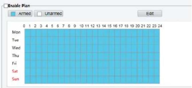
- Select Enable for Audio Detection, select a detection type and set the difference or threshold. To disable audio detection, clear the Enable check box.
The following table describes some major parameters.
| Parameter | Description |
| Detection Type | Sudden Rise: An alarm is reported when the rise of volume exceeds the difference.Sudden Falls: An alarm is reported when the fall of volume exceeds the difference.Sudden Change: An alarm is reported when the rise or fall of volume exceeds the difference.Threshold: An alarm is reported when the volume exceeds a threshold. |
| Difference | Threshold: After a volume is set as the threshold, an alarm is reported when the threshold is exceeded.Difference: the difference between two volumes. When the rise or fall of volume exceeds the difference, an alarm is reported.Note:The scale in the audio detection area is used to measure sound volume.Audio detection results are shown in real time. The red part indicates the reported audio detection alarms.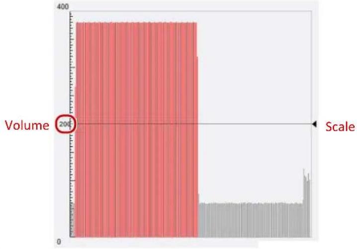 |
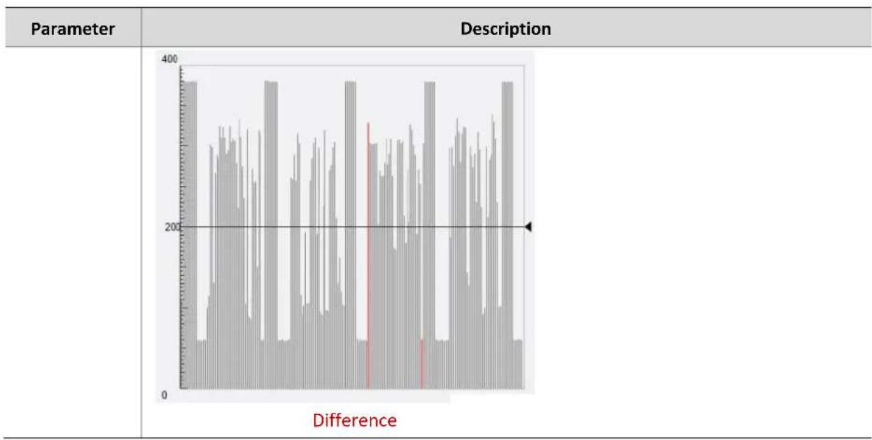
bar
-
Set the alarm-triggered actions and arming schedule as required. For the detailed steps, see the descriptions of alarm-triggered actions in Configuring Motion Detection Alarm.
-
Click Save.
Configuring Alarm Input
The camera can receive alarm information from a third-party device. To use this function, you need to configure the following information for alarm input first: port, alarm name, alarm type (normally open or normally closed) and alarm reporting time.

NOTE!
• This function is not supported by some models. Please see the actual model for details.
• The alarm triggered actions may vary with models. Please see the actual Web interface for details.
1. Click Setup>Events>Common Alarm >Alarm Input.
![Select Alarm Alarm Input 1 Alarm Name Alarm ID Alarm Type N.O. Alarm Input ● On ○ Off Trigger Actions □ Alarm Output 1 □ Goto Preset 1[DOOR] □ Upload to FTP □ Recording □ Trigger E-mail Enable Plan ■ Armed □ Unarmed Edit 0 1 2 3 4 5 6 7 8 9 10 11 12 13 14 15 16 17 18 19 20 21 22 23 24 Mon Tue Wed Thu Fri Sat Sun](/content/2026/05/958465/images/fd5f5672f2a2a910838322180f3d2ffdec505d57c2d784e6153e1223f912dba3.jpg)
- Select alarm and set the alarm name.
- Select N.O. or N.C. according to the type of the third-party alarm input device. For example, if the third-party alarm input device is normally open, you need to select N.O. here, so that the camera can receive alarm information from the third-party alarm input device.
- Set actions to be triggered by an input alarm and the plan. For the detailed steps, see the descriptions of alarm-triggered actions in Configuring Motion Detection Alarm.
- Click Save.
Configuring Alarm Output
After alarm output is triggered by a motion detection alarm, Boolean alarm, the camera can output alarm information to the third-party device if alarm output is set correctly to Normally Open or Normally Closed. The alarm output duration is configurable.

NOTE!
This function is not supported by some models. Please see the actual model for details.
1. Click Setup>Events>Common Alarm >Alarm Output.
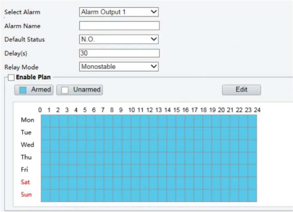
- Select the alarm and set the alarm name.
- Set the status to N.O. (default setting) and set the alarm duration.
- Set relay mode to better adapt to third-party alarm devices like alarm lights. Please select the trigger mode according to your third-party alarm device.
| Item | Description |
| Monostable | The alarm output triggers the third-party alarm device by pulse. |
| Bistable | The alarm output triggers the third-party alarm device by high or low level. |
- Set actions to be triggered by an input alarm and the plan. For the detailed steps, see the descriptions of alarm-triggered actions in Configuring Motion Detection Alarm.
- Click Save.

CAUTION!
Strictly follow the sequence when powering on the devices to avoid damaging camera components:
- Check that the alarm type is set to Normally Open (default setting), and that the camera and the alarm output device are powered off.
- After completing the connection, power on the camera first and then power on the alarm output device.
Memory Card Storage

NOTE!
- This function is not supported by some models and may vary with models. Please see the actual model for details.
- Edge storage is recommended when the camera operates in stand-alone mode. When the camera is managed by the central management server, you need to stop edge storage to avoid affecting the cache post recording service.
- Post-Record is displayed if the camera is capable of this feature; This parameter is not displayed if not supported by the camera
Edge storage is used to save video data and snapshots to the memory card directly. Edge storage is recommended when the camera is running in stand-alone mode.
Manual storage
The camera records live video repeatedly if manual storage is enabled.
1. Click Setup>Storage>Storage.
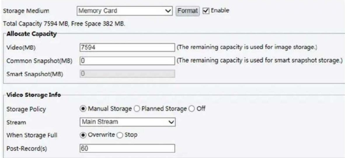
- Start edge storage and modify the settings as required. The following table describes some major parameters.
| Parameter | Description |
| Storage Medium | Storage resource type.Note:To format the memory card, disable the storage function for the card first. Then Click Format and then click OK to confirm the operation. The system will restart when the format is completed.Information about the total and free space is displayed. |
| Data Overwrite Policy | Overwrite: If there is no free space in the memory card, new data will overwrite the existing data repeatedly.Stop: If there is no free space in the memory card, new data will not be saved to the memory card. |
| Post-Record(s) | For alarm-triggered recording, length of time that recording continues after the end of the alarm. |
3. Click Save.
Planned storage
If planned storage is enabled, the camera records video to the memory card during the specified periods.
1. Click Setup>Storage>Storage.
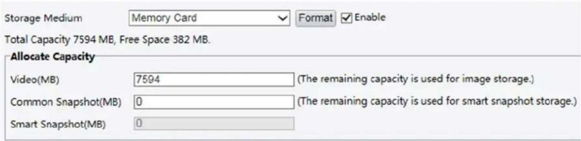
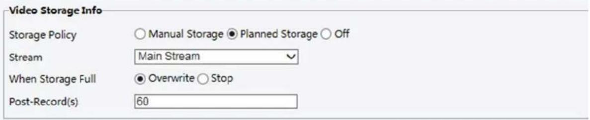
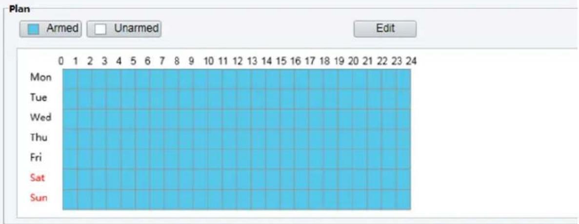
bar
| Day | Armed | |---|---| | Mon | 0 | | Tue | 1 | | Wed | 2 | | Thu | 3 | | Fri | 4 | | Sat | 5 | | Sun | 6 |For some camera models, the page is displayed as follows.
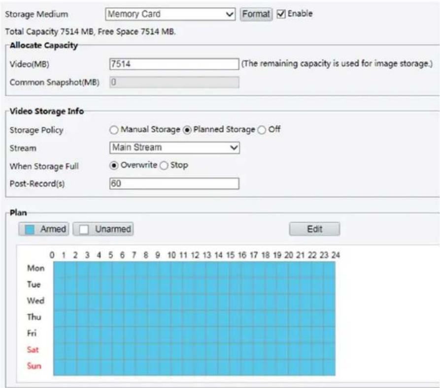
- Select Planned Storage, and then set the periods during which the camera records video to the memory card.
- Click Save.

NOTE!
- Planned storage is not effective when manual storage and planned storage are both enabled.
• To query recordings in the memory card, see Video Playback and Download with Edge Storage.
Setting Cache Post Recording
A camera under centralized management can use the memory card as a backup storage resource of the central management server. If storage from the camera to the central storage device is interrupted due to unstable network connection, the camera automatically will start cache post recording and store videos to the memory card.
With recording backup enabled, the camera can automatically transfer the video stored in the memory card to a storage resource of the backup server in form of file when the communication between the camera and the backup server is restored.

NOTE!
Before you set cache post recording for a camera, check that:
• The memory card is correctly installed on the camera.
• Backup resource has been added on the central server.
• Backup resource has been allocated for the camera.
- Post-Record is displayed if the camera is capable of this feature; This parameter is not displayed if not supported by the camera
Disable edge storage
1. Click Setup>Storage>Storage.
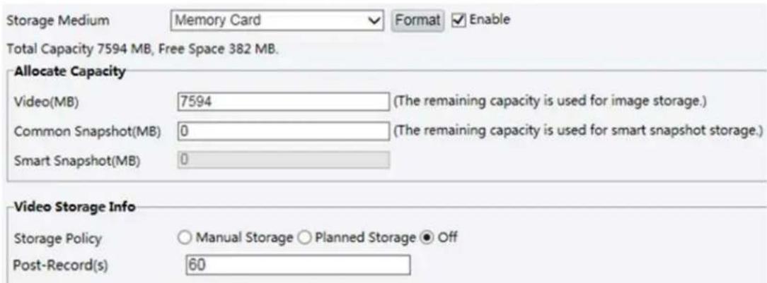
-
Set Storage Policy to Off. Post-Record is displayed if the camera is capable of this feature and then set Post-Record(s).
-
Click Save.
System Maintenance

NOTE!
This function is not supported by some models. Please see the actual model for details.
Security
User Management
There are two types of users in the system:
- Administrator: referred to as "admin" in this manual. The default name of the administrator is admin, which cannot be modified. Admin has full permission and can manage all users and devices. Only one admin user is allowed in the system.
- Common user: referred to as "user" in this manual. User only has permission to play live and recorded video. Up to 32 common users are allowed in the system.
You can add a user on the user management interface (under Setup>Security>User).
After the user is added successfully, you can change the password by entering the new password or delete the user by clearing the username.

NOTE!
- Only admin can change passwords. Changing the username or password for a user when the user is still logged in will force the user to log out. The user must use the new username or password to log in.
- Only admin can add and delete users. Deleting a user when the user is still logged in will force the user to log out. A deleted user cannot log in.
Setting Secure Data Transmission
Set a secure channel for data transmission to ensure security.
NOTE!
This function is not supported by some models. Please see the actual model for details.
1. Click Setup>Network>Port.
| HTTP Port | 80 |
| HTTPS Port | 443 |
| RTSP Port | 554 |
- Enter the port number in the HTTPS Port text box.
- ClickSave.
- Click Setup>Security> Network Security> HTTPS.

- Select On for HTTPS.You may import a custom SSL certificate as needed.
- Click Save.
Next time you log in, enter the address in https://IP:HTTPS port number format, for example, https://192.168.1.13:443 to enter secure channel mode. If you use the default HTTPS port, enter https://IP.
Authentication
RTSP (Real Time Streaming Protocol) is an application layer protocol. To transmit and control the audio and video, set RTSP authentication on the Web interface.
1. Click Setup>Security> Network Security>Authentication.
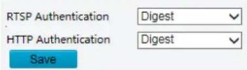
- Select an authentication mode and then click Save.
Hide Vendor Information
You can set to hide the vendor information of the network camera on the Web interface.
1. Click Setup>Security> Registration Info.
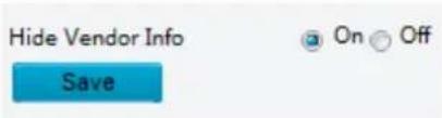
- Under Registration Info, select On.
- Click Save.
APR Protection
This function protects a camera from ARP attacks. The gateway and the MAC address must be set properly before a PC can access the camera from another network; if an incorrect MAC is set, only PCs on the same LAN can access.
- Click Setup> Security> Network Security> ARP Protection.
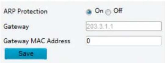
- Select the check box to enable the ARP binding function and set the gateway MAC address.
- Click Save.
IP Address Filtering
Use IP address filtering to allow or forbid access from specified IP address(es).

NOTE!
This function is not supported by some models. Please see the actual model for details.
1. ClickSetup>Security > Network Security>IP Address Filtering.
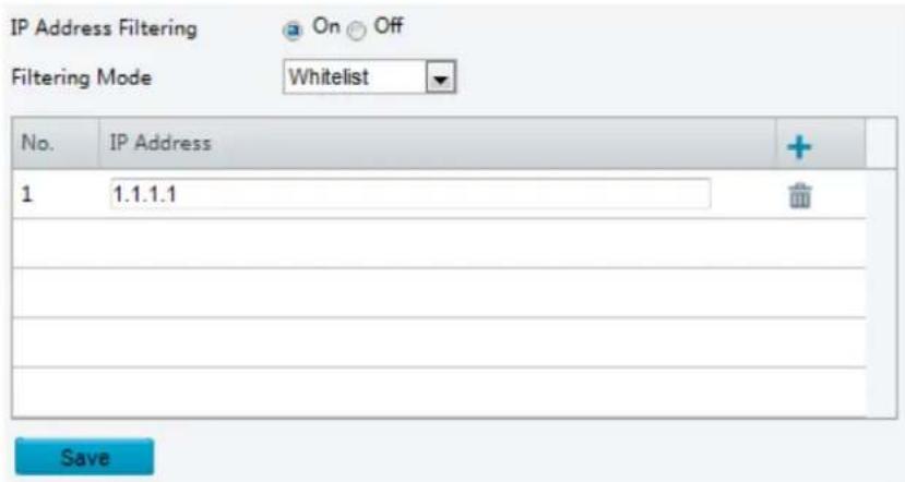
- Select On to enable IP address filtering.
- Select a filtering mode, and then add IP address(es).
- Click Save.

NOTE!
- If Filtering Mode is set to Whitelist, then only the added IP address(es) are allowed to access the camera. If Filtering Mode is set to Deny Access, then only the added IP address(es) are not allowed to access the camera.
- Up to 32 IP addresses are allowed. Each IP address can be added once only.
- The first byte of each IP address must be 1-223, and the fourth cannot be 0. For example, the following IP addresses are illegal and cannot be added: 0.0.0.0, 127.0.0.1, 255.255.255.255, 224.0.0.1.
Access Policy
1. Click Setup> Security> Network Security> Access Policy.
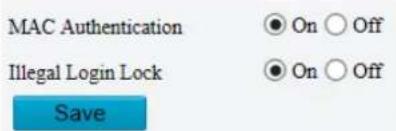
- Select On to enable Illegal Login Lock and MAC Authentication.
- Click Save.
Watermark
Use watermark to encrypt custom information with video to prevent unauthorized delete or alteration.

NOTE!
Only some camera models support this function.
1. ClickSetup>Security>Watermark.
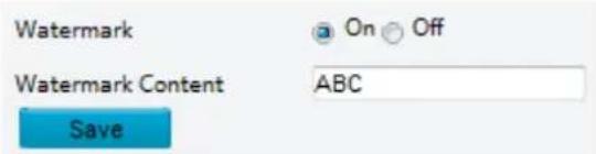
-
Select On to enable watermark, and then input watermark content.
-
Click Save.
Setting the System Time
You can use the following methods to adjust the system time of your device.
Manually Setting or Synchronizing the System Time
- Click Setup>Common>Time, and then click the Time tab.

-
Select a synchronization mode.
-
Set the correct time zone and system time. You may also click Sync with Computer Time to synchronize the time settings of your camera with that of your PC.
-
Click Save.
Synchronizing with the NTP Server
- Click Setup>Common>Time, and then click the Time tab.
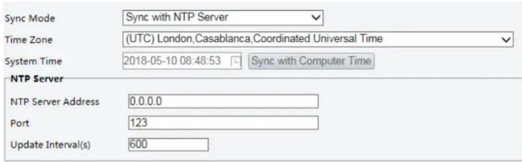
- Set Sync Mode to Sync with NTP Server, and then set the IP address and port of the NTP server and update interval.
- Click Save. The camera will periodically synchronize time with the NTP server.
Setting the DST
- Click Setup>Common>Time, and then click the DST tab.
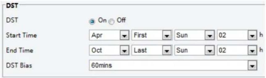
-
Select On for DST, set the start time, end time, and DST bias.
-
Click Save.
Setting Servers
Intelligent Server
You need to configure the intelligent server if an ultra-sensitive camera is managed by a central server.

NOTE!
• Only some camera models support intelligent server.
• The settings may vary with device model.
• To use face snapshot, you need to configure the TMS server to which snapshots are uploaded.
- Click Setup>Common>Server, and then click the Intelligent Server tab.
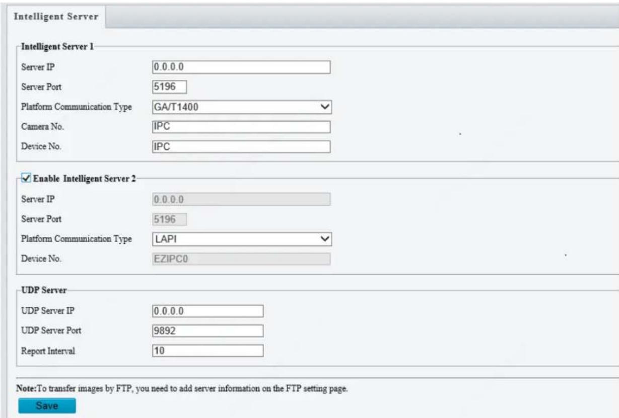
- Set intelligent server parameters. Main parameters are as follows.
• Server IP, Server Port: use the default value.
• Platform Communication Type:
a. Choose GA/T1400, then enter device ID, username and password.
b. Choose FTP, then click the FTP button to go to the FTP settings page and complete the settings.
c. Choose LAPI to connect to VMSes.
- Video & Image Database Settings: choose Pixel Mode or Percentage Mode to display the coordinate information of detection objects.

NOTE!
• Video & Image Database Settings is available to certain models only.
- Pixel mode coordinate X/Y= (Percentage mode coordinates*image width/height)/10000.
- Select Enable Intelligent Server 2, and complete the settings, then the snapshot stream and video stream will be uploaded to Intelligent Server 1 and Intelligent Server 2 at the same time.

NOTE!
• Intelligent Server 2 is available for certain models only.
- If the communication type of Intelligent Server 1 is set to FTP, then FTP cannot be set as the communication type of Intelligent Server 2.
- Only certain camera models support LAPI protocol, and only Intelligent Server 2 supports LAPI. When LAPI is chosen, the settings cannot be configured.
- Click Save.
Serial Port Mode Configuration
The RS485 serial port is used for data exchange with the third-party device. Serial port settings on the camera should be consistent with that of the connected third-party device.

NOTE!
This function is not supported by some models. Please see the actual model for details.
PTZ control
To control a PTZ camera through a third-party device, you need to set Port Mode to PTZ Control.
By sending PELCO-D compliant PTZ control commands through the RS485 port, you can control the PTZ camera without using the PTZ control panel.
-
Click Setup>System>Ports & Devices, and then click the Serial Port tab.
-
Select PTZ Control from the Port Mode drop-down list. The following table describes some major parameters.
| Parameter | Description |
| PTZ Protocol | Set the PTZ protocol that the channel supports.Note:You can set this parameter only whenPort Modeis set to PTZ Control.WhenPTZ Protocols is set toINTERNAL-PTZ, the camera can connect to the external PTZ without using the serial port (serial port parameters are grayed out). In this case, you only need to connect the zoom and focus interfaces of the camera to the lens, and then you can operate the PTZ like an internal PTZ. |
| PTZ Mode | Built-in PTZ Priority: When this option is selected, the camera first tries to control the PTZ (for example, to zoom or focus) by itself instead of through the external PTZ. For operations that the camera cannot accomplish by itself, the camera uses the external PTZ.External PTZ Priority: The camera first tries to control the PTZ through the PTZ connected through the serial port.Note:You can set this parameter only whenPort Modeis set to PTZ Control.WhenINTERNAL-PTZis selected, this parameter is always set toBuilt-in PTZ Priority, and it is unnecessary to connect the camera to an external PTZ through the serial portControl through the external PTZ is not effective even when the camera has been connected to an external PTZ.Set this parameter as required. Make sure PTZ control related interfaces are correctly connected. |
| Address Code | Set the address code for the PTZ.Note:You can set this parameter only whenPort Modeis set to PTZ ControlandPTZ Protocols is not set toINTERNAL-PTZ. |
- Click Save.
Transparent channel
Use the RS485 serial port to achieve transparent data transmission with the third-party device. Transparent channel is mainly used to achieve transparent data transmission between two devices.

NOTE!
-
This function is not supported by some models. Please see the actual model for details.
• Make sure that you have set Port Mode to Trans-Channel for your camera. -
Click Setup>System>Ports & Devices, and then click the Serial Port tab.
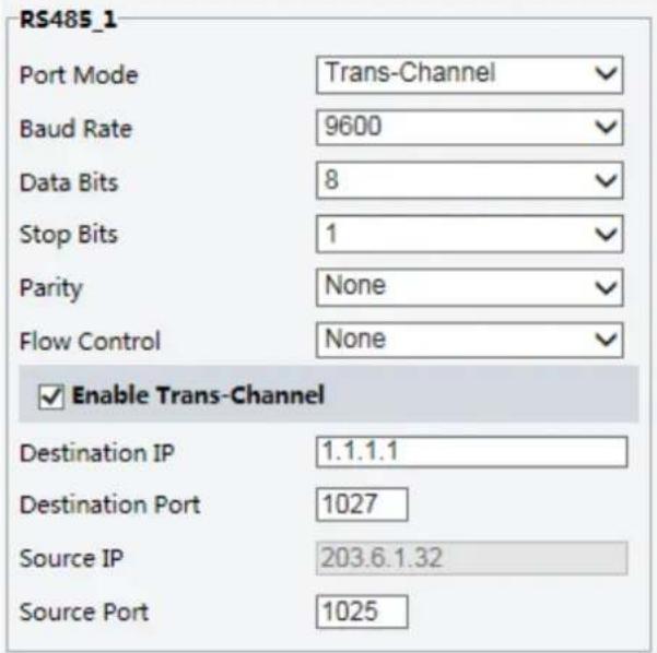
- Select Trans-Channel from the Port Mode drop-down list.
- Select Enable for Trans-Channel.
- Enter the destination IP address and port number (IP address and port number that the transparent channel connects to).
- Click Save.
OSD
To display information from the third-party device on the OSD, you need to select OSD as the port mode.
The camera receives information from the third-party device through the RS485 serial port, translates the received information, and then displays it on the OSD.

NOTE!
To enable the camera to correctly translate information received from the third-party device, make sure that the information sent by the third-party device through the serial port complies with the data format specified by our company. For more details, contact your dealer.
- Click Setup>System>Ports & Devices, and then click the Serial Port tab.
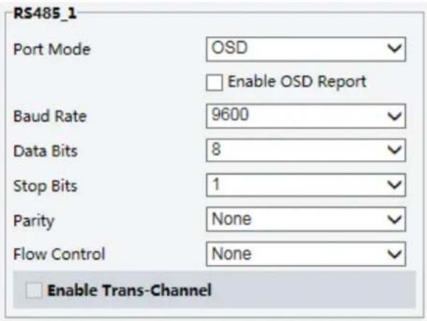
-
Select OSD from the Port Mode drop-down list. Select Enable OSD Report (so OSD data will be uploaded to the platform).
-
Click Save.
ONVIF Transparent Channel
Transmit data through the transparent channel (ONVIF) between the camera's RS485 port and a third-party device.
- Click Setup>System>Ports & Devices, and then click the Serial Port tab.
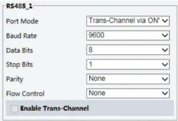
-
Set Port Mode to Select Trans-Channel via ONVIF.
-
Click Save.
Wiper Control
Set wiper parameters before you can control the wiper.

NOTE!
This function is not supported by some models. Please see the actual model for details.
- Click Setup>System>Ports & Devices, and then click the External Device tab.
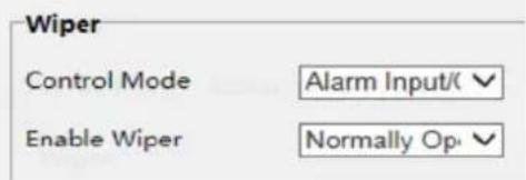
- Set control mode for the wiper. The following table describes some major parameters.
| Parameter | Description |
| Serial Port | The wiper is controlled by PELCO-D instructions; therefore, the PTZ protocol should be set to PELCO-D. See PTZ control for details. |
| Alarm Input/Output | Use alarm input and output to open or close the circuit and control the wiper. |
Viewing Device Status
You can view the current status of your camera.
- Click Setup>Common>Basic Info.
| Basic Info | |
| Model | IPC |
| Firmware Version | IPC |
| Hardware Version | A |
| Boot Version | V1.0 |
| Serial No. | 2102335CC3531740100232 |
| Network | 192.168.1.13/ 255.255.255.0/ 192.168.1.1 |
| MAC Address | 48:ea;63:4d :56:88 |
| Status | |
| System Time | 2018/ 1/ 25 19:16:27 |
| Operation Time | 0 Day(s) 0 Hour(s) 0 M Inute(s) |
| Intelligent Server | Offline |
- Click Refresh for the latest status information.
- View the device information.

NOTE!
You may view device model, firmware version, intelligent server status, etc., on the basic info page.
Photo Storage Status
View the current photo storage status. See Memory Card Storage for the full storage policy.

NOTE!
Only models with storage function support this function. Please see the actual model for details.
- Click Photo.
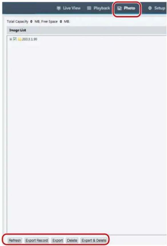
- Click Refresh to update the storage status.
- You can export or delete photos in the Image List area.
Upgrading the Device
If the device is managed by the central management server and you want to upgrade the devices in batch mode, it is recommended to perform the upgrade operation on the central server. For detailed steps, see the user manual for the central management server.
1. Click Setup>System>Maintenance.

- Under Software Upgrade, click Browse and select the correct upgrade file.
- Click Upgrade and then confirm to start. The camera will restart automatically after the upgrade is completed. Some devices support boot program upgrade. To upgrade, select Upgrade Boot Program.
- You may click Detect to check for new versions available to cloud upgrade.

NOTE!
- You must use the correct upgrade file for you camera. Otherwise, unexpected results may occur.
• The upgrade file is a ZIP file and must include all the necessary files. - The boot program loads the operating system and then the system starts running. The upgrade boot program function is disabled by default, and only the camera will be upgraded to the latest version. If enabled, both the camera and the boot program are upgraded, and the operating system of the following new version scan be booted properly and the camera can be upgraded conveniently.
- Ensure that the power supply is normal during upgrade. The device will restart after the upgrade is completed.
Restarting the System
1. Click Setup>System>Maintenance.

- Under Device Restart, click Restart. The device will restart after you confirm the operation.

CAUTION!
Perform this operation with caution because restarting the system interrupts the ongoing service.
Importing and Exporting System Configuration File
Export the current configurations of the camera and save them to the PC or an external storage medium. You can also quickly restore configurations by importing backup configurations stored on the PC or an external storage medium back to the camera.

CAUTION!
- After you perform the Default operation, all settings are restored to factory defaults, except the following: login password of the system administrator, network settings, and system time.
- Make sure you import the correct configuration file for your camera. Otherwise, unexpected results may occur.
• The camera will restart when the configuration file is imported successfully.
1. Click Setup>System>Maintenance.

- To import configurations that you have backed up, click Browse next to the Import button and select the configurations you want to import, and then click Import. The result will be displayed.
-
To export current system configurations, click Browse (next to the Exporting field), set the destination and then click Export.
-
To restore default configurations, click Default and then confirm the operation. The device will restart and restore the default configurations. Clicking Default with the check box selected will completely restore the device to factory default settings.
Collecting Diagnosis Information
Diagnosis information includes logs and system configurations. You can export diagnosis information to your PC.
1. Click Setup>System>Maintenance.

- In the Diagnosis Info area, click Browse to set the destination and then click Export.

NOTE!
- Diagnosis information is exported to the local folder in form of a compressed file. You need to decompress the file using a tool such as WinRAR and then open the file using a text editor.
- By selecting Collect Image Debugging Info, you can display video with debugging information at the same time, which makes troubleshooting easier.
Focus Configuration
The device can adjust the speed of auto-focus according to the minimum focus distance. In order to shoot clear objects, it is recommended that the minimum focus distance is set shorter than the distance between the objects and lens, for example, if the minimum focus distance is 3m, then the objects within 3m from lens will be out of focus.

NOTE!
This function is only supported by the devices with auto-focus. Please see the actual model for details.
1. Click Setup>System>Maintenance.

- Under Focus, configure Min. Focus Distance(unit: cm) and Max. Zoom Ratio.
- Click OK.
Device Mounting Height
Enter the actual height from the installed infrared dome to the ground, so that the dome will be able to automatically adjust its infrared lamp.

NOTE!
This function is only supported by some infrared cameras. Please see the actual model for details.
1. Click Setup>System>Maintenance.

- Enter the actual height from the installed Infrared Dome to the ground.
- Click OK.
Fisheye Camera Parameter
To display video properly, you need to set fisheye parameters properly according to the actual mounting mode.

NOTE!
This function is only supported by fisheye cameras. Please see the actual model for details.
- Click Live View>Mount. Select the mounting mode. The selected mounting mode must be consistent with the actual mounting mode.
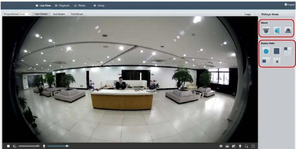
For some camera models, the page is displayed as follows.
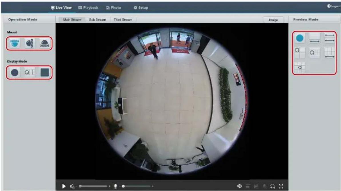
- Set the parameters. The following table describes some major parameters.
| Parameter | Description |
 | |
 | |
 | Eleven display modes:Original ImagePanoramicPanoramic+3PTZPanoramic+4PTZPanoramic+8PTZ360°Panoramic+1PTZ180°PanoramicFisheye+3PTZFisheye+4PTZ360°Panoramic+6PTZFisheye+8PTZ |
 | |
 | |
 | |
 | |
 | |
 | |
 | |
 | |
 | Three mounting modes:CeilingWallDesktopNote:The selected mounting mode must be consistent with the actual mounting mode. |
 | |
 |
4 Live View
Live view means playing live video (real-time audio and video) received from a camera in a window through the Web interface.
If you log in with the Live View check box selected, live video appears by default when you are logged in. You may double-click the window to enter or exit full screen mode.
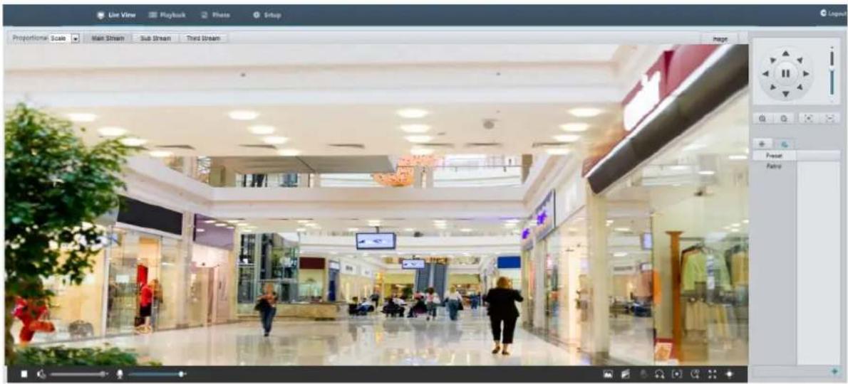
Live View Toolbar

NOTE!
The supported live view operations may vary with camera model. For the operations that your camera supports, see the Web interface.
| Button | Description |
 | Play/stop live video. |
 | Adjust the output volume for the media player on the PC. |
 | Adjust the microphone volume on the PC during audio communication between the PC and the camera. |
| [2372] | Take a snapshot of the current image displayed on the PC.Note:The path for saving snapshots are setinSystem Configuration. |
| [SDC0] | Start/stop local recording.Note:The path for saving local recordings is setinSystem Configuration. |
 | Start/stop audio communication between the PC and the camera. |
 | Start/stop digital zoom. For more details, seeUsing Digital Zoom. |
 | Start/stop area focus. For more details, seeUsing Area Focus. |
 | Start/stop 3D positioning. For more details, seeUsing 3D Positioning. |
 | Show/hide the PTZ control panel. |
  | Set image display ratio in the window. For example, to display high-definition images at original 16:9, selectScale; to display according to window size, selectStretch; to display with the original image size, selectOriginal.Reset the packet loss rate to zero.Note:After you move the mouse cursor on a live view window, this button appears on the floating toolbar. |
| [6A0W] | Display packet loss rate and bit rate information at the bottom of the window.Note:After you move the mouse cursor on a live view window, this button appears on the floating toolbar.Click this button to always display the information. With another click, the information appears only when you move the mouse cursor over the window or place it at the bottom. If the mouse cursor rests on the window for around 3 seconds or leaves the window, the information disappears. |
 | Click this button to open the image setting page. |
 | Display in full screen mode. |
 | Select a live video stream that the camera supports: main stream, sub stream or third stream. |
| [2BD3] | |
| [SWHZ] |
Viewing Certain Area of Images
Digital zoom, area focus and 3D positioning allow you to get more details of certain part of images. Digital zoom enlarges an image with loss in image quality, while 3D positioning enlarges an image without.
Using Digital Zoom

NOTE!
The supported live view operations may vary with camera model. For the operations that your camera supports, see the Web interface.
- On the Live View page, click 📤 on the toolbar.
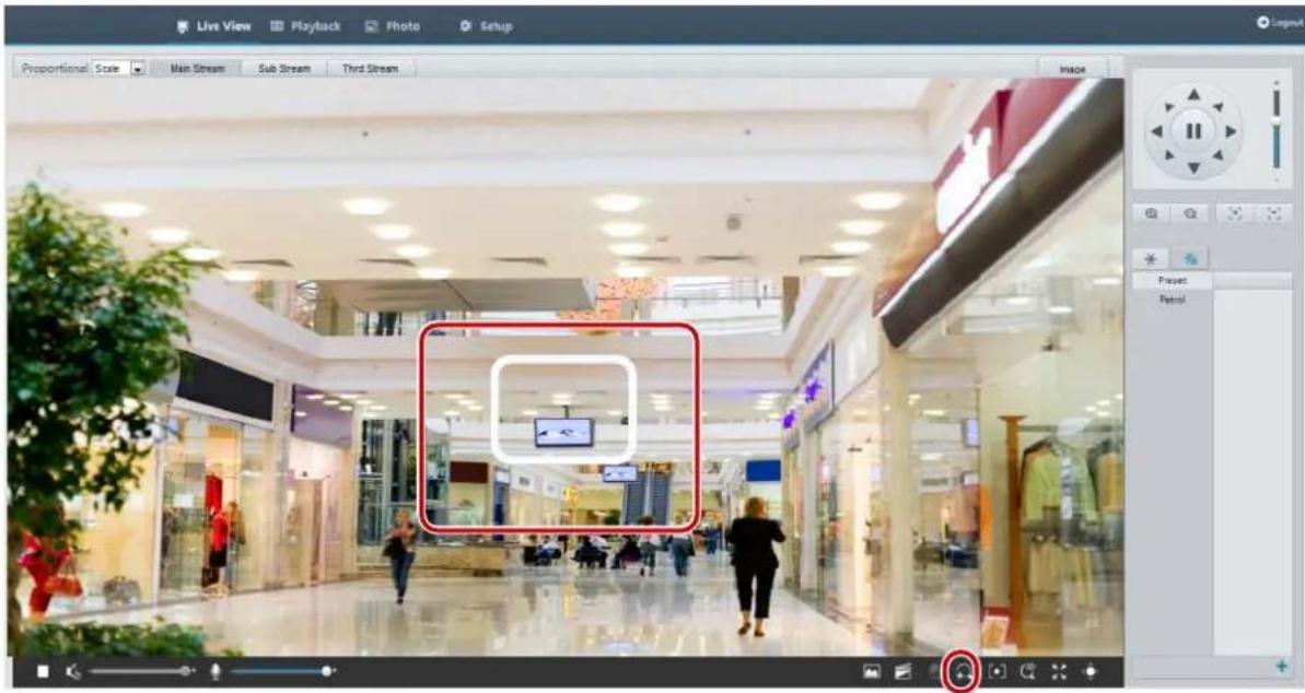
-
Click and hold the mouse button, and then drag from top down (draw a rectangle) to specify an area. To restore the original image size and zoom in on other areas of the image, right-click the mouse.
-
To exit, click .
Using Area Focus

NOTE!
The supported live view operations may vary with camera model. For the operations that your camera supports, see the Web interface.
- On the Live View page, click [●] on the toolbar.
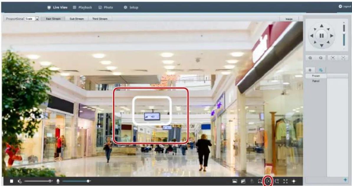
-
Click and hold the mouse button, and then drag from top down (draw a rectangle) to specify an area.
-
To exit, click

Using 3D Positioning

NOTE!
This function is available only for network PTZ cameras and network box cameras equipped with motorized zoom lens and PTZ. Please see actual models for details.
- On the Live View page, click

on the toolbar.
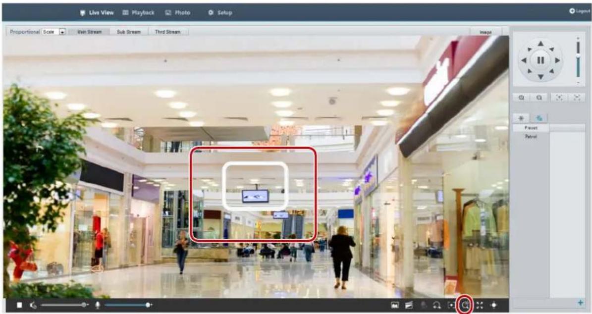
-
Click and hold the mouse button, and then drag from top down (draw a rectangle) to specify an area. Dragging reversely (from down top) will zoom out.
-
To exit, click

Face Snapshot
- In live view page, click in the tool bar.

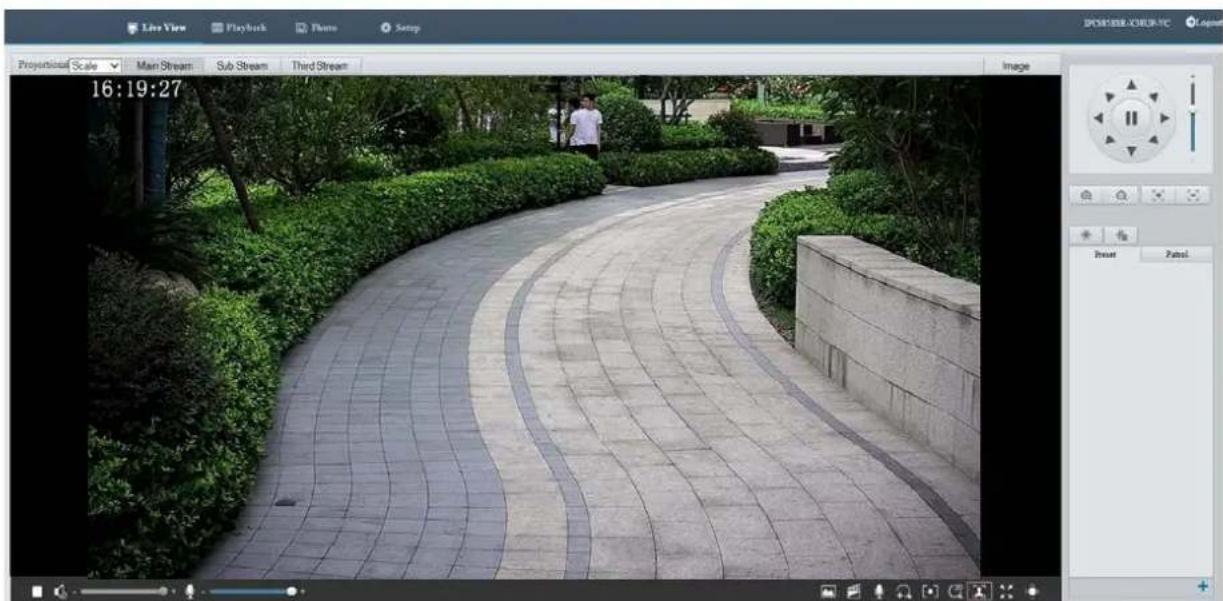
natural_image
Landscape photo of a paved path with curved stone pavement, bordered by green hedges and trees, with a person walking along the path (no visible text or symbols)- Snapshot list will be displayed on the right of live view, with the latest on top. Up to 200 snapshots will be displayed. The following figure shows an example.
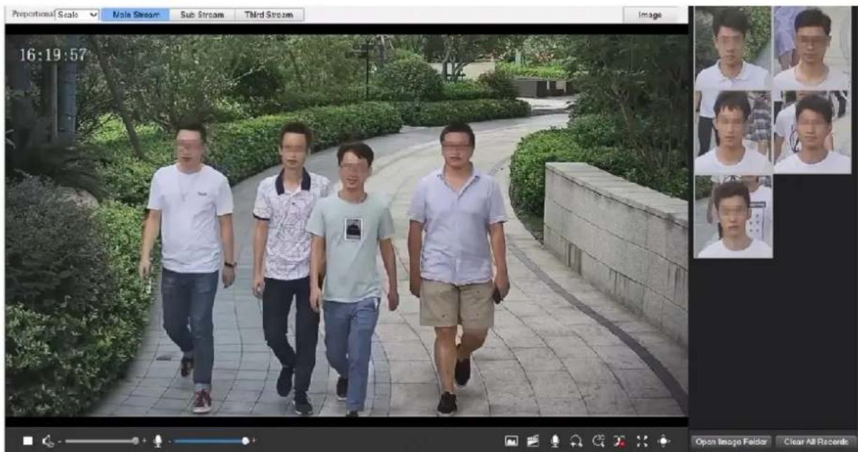
- Some models support structured data which indicates the attributes of detection objects. To display the attributes in live view page, you need to select Attribute Collection in Common Alarm Configuration.
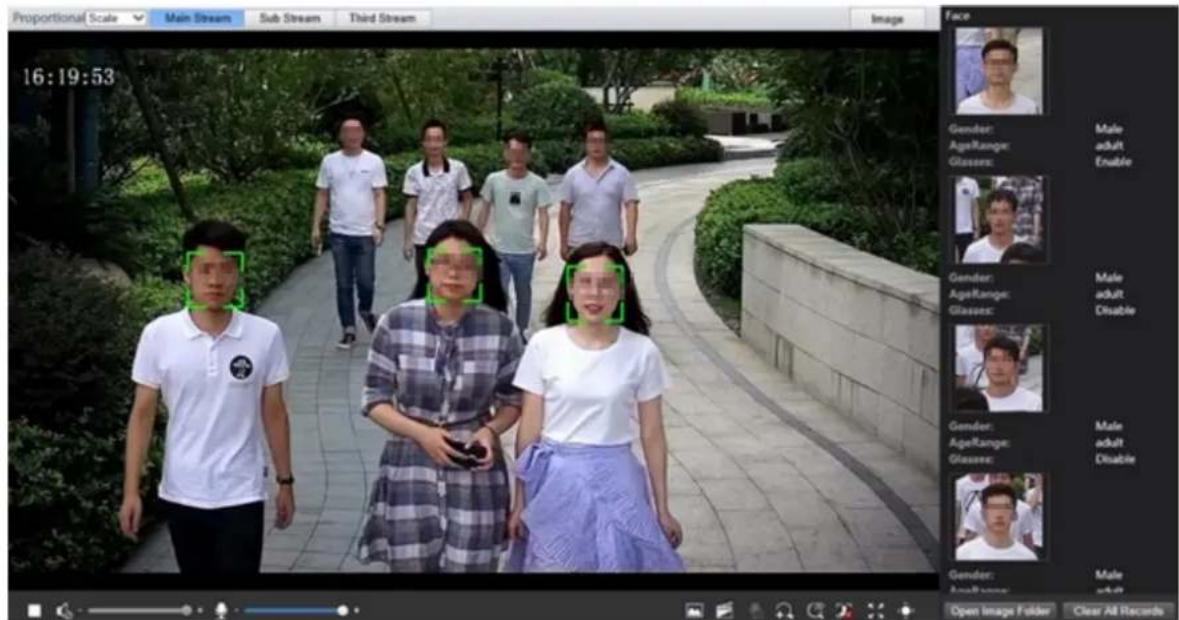
- Some models support human body snapshot association. To display the human body picture in live view page, you need to select human body snapshot in Face.
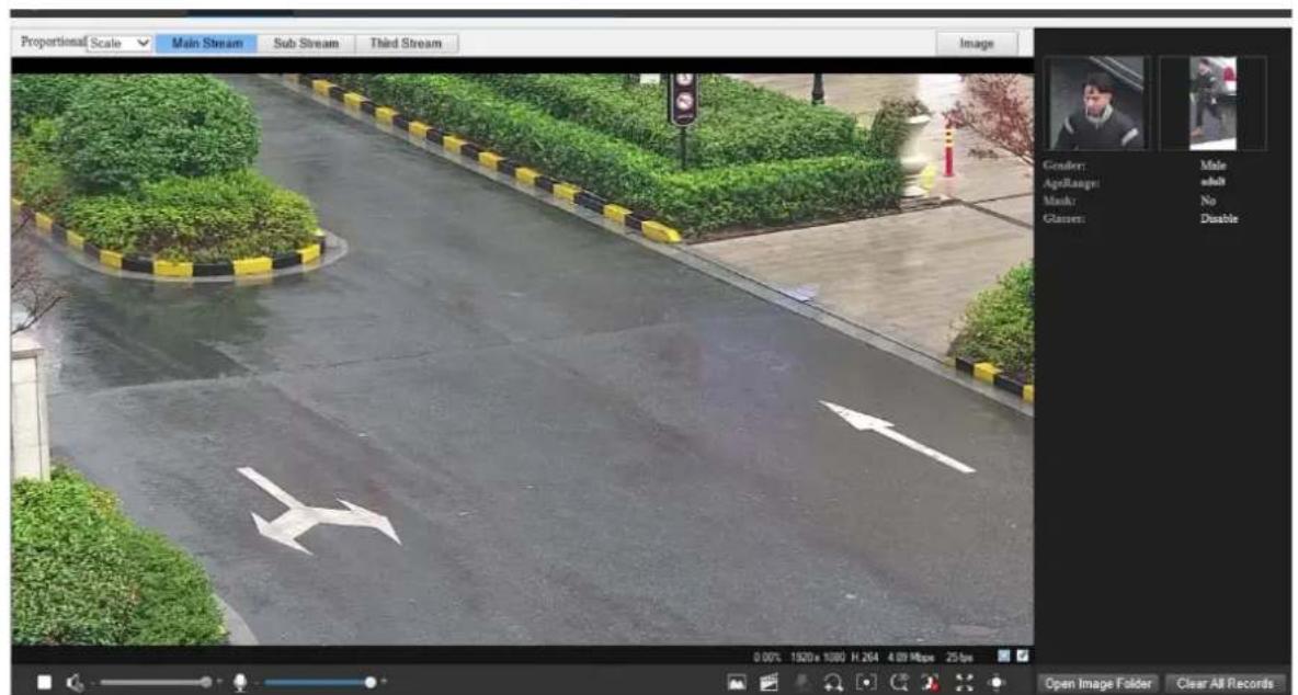
- Click to stop face snapshot display.
- Click Open Image Folder to view the snapshots saved in your PC. The snapshots are saved in JPEG format. You may also change the image path in Setup > Common > Local Parameters. When the disk space is smaller than 100MB, you will be prompted to clear auto snapshot folder, and new snapshots will not be displayed in live view page until disk space is freed.
- Click Clear All Records to clear the snapshots.

NOTE!
Only some camera models support this function, and the actual interface may vary.
- In live view page, click in the tool bar.
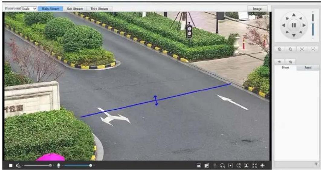
- To display structured data of detection objects in live view page, you need to select Attribute Collection in Common Alarm Configuration. The following figure shows an example.
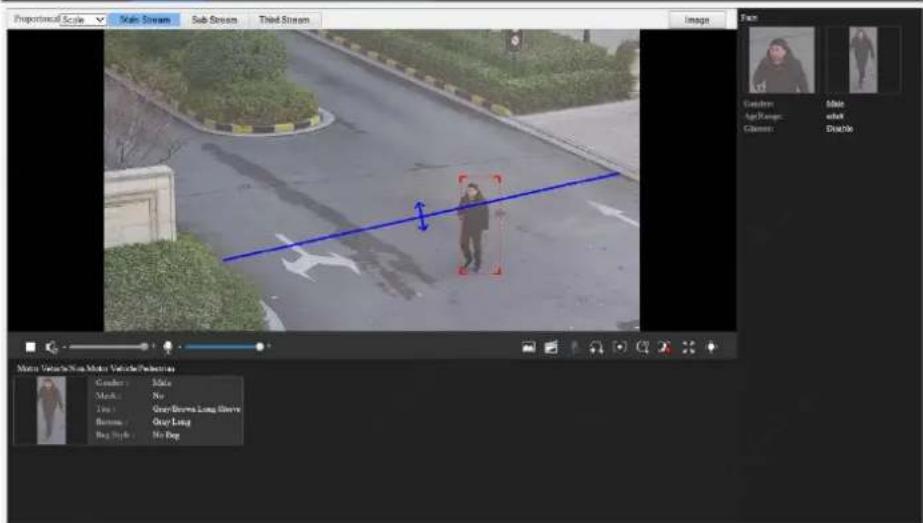
-
Click to stop deep perimeter snapshot display.
-
Click Open Image Folder to view the snapshots saved in your PC. The snapshots are saved in JPEG format. You may also change the image path in Setup > Common > Local Parameters. When the disk space is smaller than 100MB, you will be prompted to clear auto snapshot folder, and new snapshots will not be displayed in live view page until disk space is freed.
Click Clear All Records to clear the snapshots. Mixed-Traffic Detection Snapshot

NOTE!
Only some camera models support this function, and the actual interface may vary.
- In live view page, click in the tool bar.
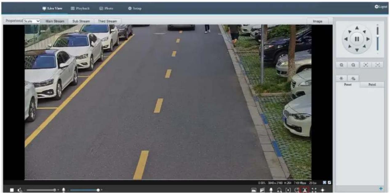
- To display structured data of detection objects in live view page, you need to select Attribute Collection in Common Alarm Configuration. The following figure shows an example.
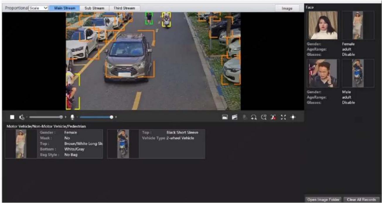
-
Click to stop displaying snapshots.
-
Click Open Image Folder to view the snapshots saved in your PC. The snapshots are saved in JPEG format. You may also change the image path in Setup > Common > Local Parameters. When the disk space is
smaller than 100MB, you will be prompted to clear auto snapshot folder, and new snapshots will not be displayed in live view page until disk space is freed.
- Click Clear All Records to clear the snapshots.
Live View of Fisheye Cameras

NOTE!
• This function is only supported by the network fisheye cameras. Please see actual models for details.
- The preview image on the Web may vary with the fisheye settings for the camera. Please set the fisheye parameters (see Fisheye Cameras Parameter) and the fisheye mode of the camera before you start live view.
Display modes include three major types: Original Image, Fisheye and PTZ, Panoramic and PTZ. In different mounting modes, images are displayed differently. The following takes wall mount as an example.
When Original Image is selected, fisheye images are displayed as follows.
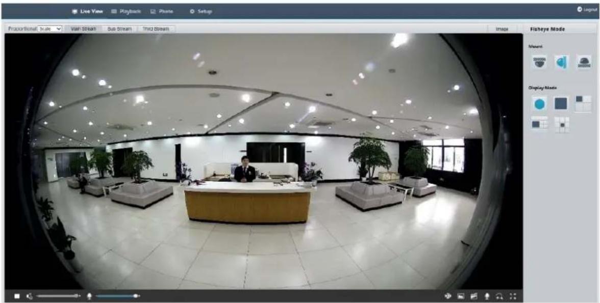
natural_image
Interior view of a modern office lobby with reception desk and potted plants, captured through a circular lens (no visible text or symbols)When Panoramic is selected, dewarped panoramic images are displayed as follows.
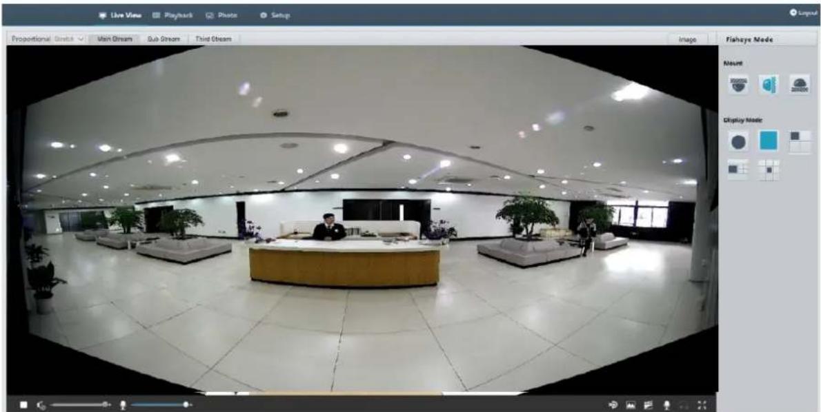
natural_image
Panoramic interior view of a modern lounge or reception area with reception desk and potted plants (no visible text or symbols)
NOTE!
If the ceiling mount or desktop mount is adopted, the panorama image (two 180° images) is a dewarped image of the fisheye preview image (360° image). Please mount the camera with an appropriate angle of view according to the actual surveillance requirements.
For example, if the camera is installed on the ceiling, the surveillance target is displayed on the upper part of the panorama image when the intersection angle between the device cable outlet (logo) and the surveillance target in clockwise direction is 135^ .
Position of surveillance target
(e.g. access control)
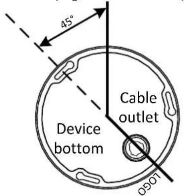
360° Fisheye image in fisheye preview mode
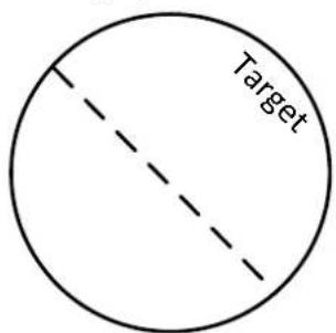
Panorama image in panorama preview mode
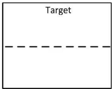
When Panoramic+4PTZ preview mode is selected from the list on the right, 4 local images are displayed, from left to right, from top to down, by default. You may perform PTZ control and zoom operations on each local image, as shown in the figure below.
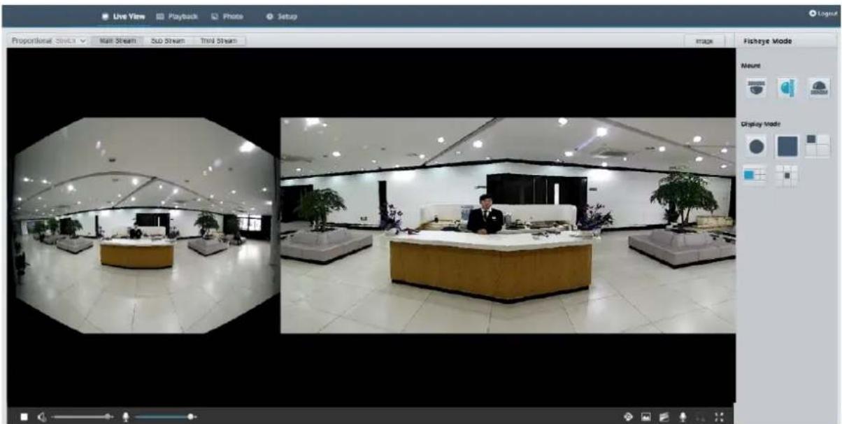
natural_image
Interior view of a modern hotel lobby with reception desk and operator at counter, showing interior lighting and floor plan (no visible text or symbols)5ePTZ of Panoramic Cameras

NOTE!
This function is available only for some certain camera models, please see actual models for details. Auto-tracking can be only supported in the main stream.
- On the Live View page, select on the toolbar as shown below.
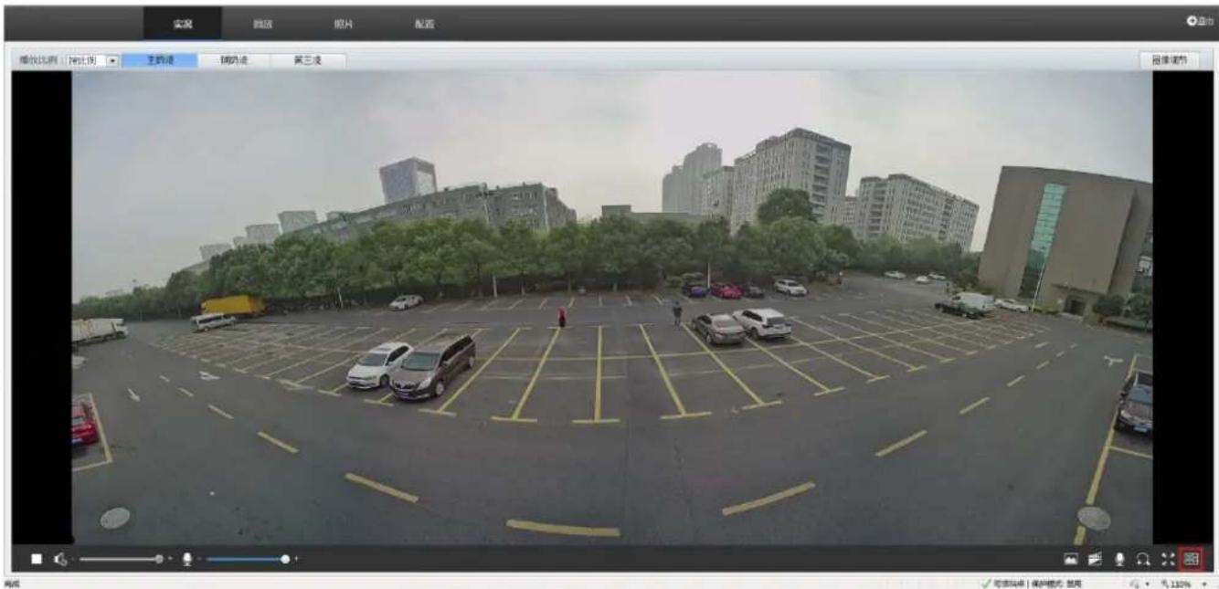
- When you click in panoramic mode, the live view would change to the 5ePTZ tracking mode. Then camera would detect moving objects in the live view when perimeter protection function is enabled, besides, it can track and enlarge 5 targets that trigger the alarm rule which you set up in perimeter protection function at most simultaneously. This function performs like a PTZ camera's tracking and zooming feature.
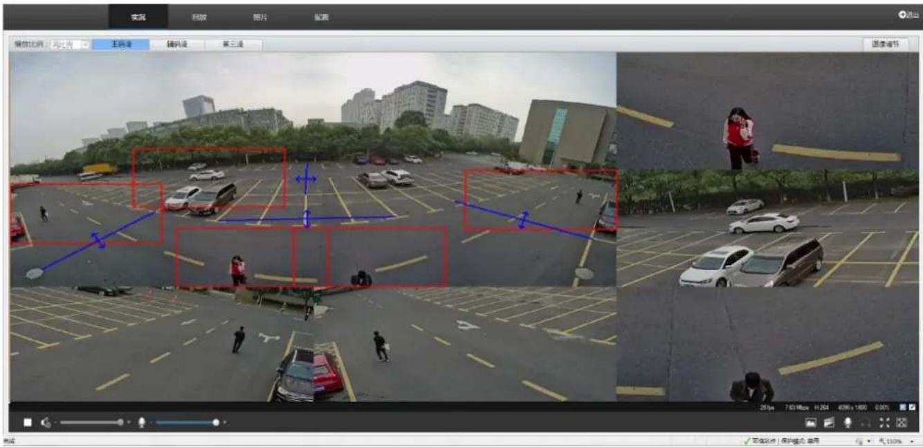
- Click in 5ePTZ tracking mode to switch to the panoramic mode.
5 Video Playback and Download with Edge Storage

NOTE!
- Edge storage refers to recording video to the memory card of a frontend device (mostly a camera). Local recording refers to recording video to a local PC client.
- Before you play back video with edge storage, check that the camera has been installed with a memory card and storage has been configured.
• This function is not supported by some models. Please see actual models for details.
Video Playback
- Click Playback on the home page.
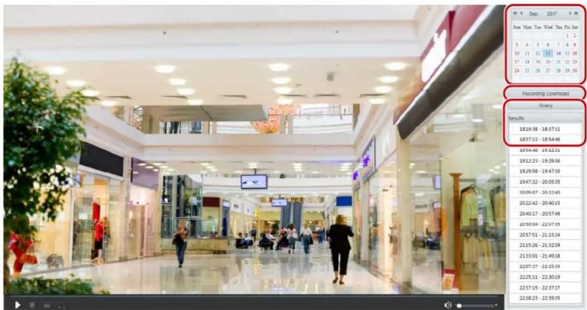
- Select the date from the calendar.
- Click Query.
- Under Results, double-click the time period to start playing the recording.
Download
- Click Playback on the home page.
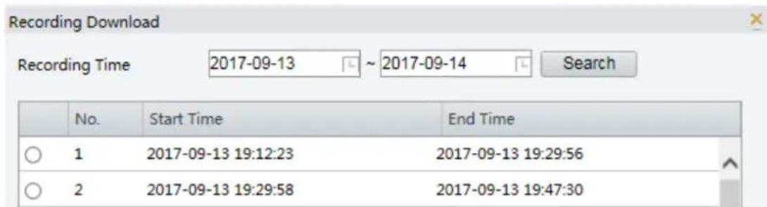
- Search for video within a specified period. The results will be shown in a list.
- Select your video and click Download. The video will be downloaded to your local path from the memory card (local path can be changed in Local Settings).
- Click Open to show the folder where the downloaded video is saved.
6 PTZ Control
This function is available only for the PTZ dome cameras or a box camera installed on a Pan/Tilt motor.

NOTE!
• Some of the lens control functions are applicable to cameras equipped with motorized lens.
- The PTZ control buttons may vary with camera model. For the PTZ control buttons that your camera supports, see the Web interface.
PTZ Control Toolbar
| Item | Description |
| Preset | Select a preset and then click ↗. The PTZ camera goes to the selected preset.To add a preset, click . To delete a preset, click . |
| Patrol | Select a patrol route and then click to start patrol.• To edit a patrol route, click . ↗• To add a patrol route, click . +• To delete a patrol route, click ☑. |
| Adjust the moving speed of the PTZ camera. | |
 | Control the direction of the PTZ camera and release the control. |
 | Turn on or off IR.Turn on or off the wiper.Turn on or off the heater.Turn on or off the illuminator.Turn on or off snow control. |
 | Adjust camera focus. |
 | Adjust camera zoom. |
 | Increase or decrease iris diameter. |
 | Shortcut keys for PTZ control. After the mouse cursor changes to one of these shapes in live view, click and hold the left mouse button to operate the PTZ camera.Note:Only PTZ dome cameras and PTZ cameras support this function.These buttons are unusable when you are using 3D positioning or digital zoom. |
 | Shortcut keys for zooming in or out in live view. Scroll the wheel forward to zoom in or backward to zoom out.Note:Only cameras with motorized zoom lens support this function. |
Setting Patrol by Presets
Setting Presets
On the Preset tab, you can manage presets or perform certain control operations to the PTZ camera. For more details, see PTZ Control Toolbar.
Add a preset
- On the Live View page, click Preset on the control panel.
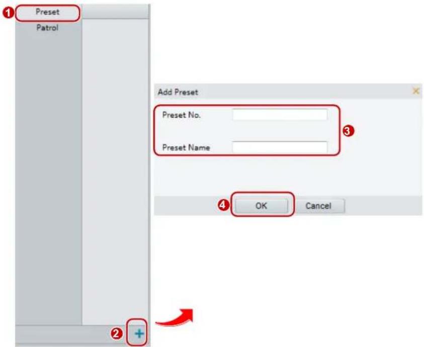
- Adjust the camera till it points toward the desired direction.
- Adjust zoom and focus as needed to obtain the optimal image.
- Click + to add it as a preset. Enter a number and name for the preset and then click OK.
Go to a preset
- On the Live View page, click Preset on the control panel.
![1 Preset Patrol 1 2 [DOOR]](/content/2026/05/958465/images/4cfea05d8c314ecbaa6bef68a9b8638c32db56f306983cb2ff7af76622046deb.jpg)
- Click → for a preset. The PTZ camera goes to the selected preset.
Delete a preset
- On the Live View page, click Preset on the control panel.
![1 Preset Patrol 1 [DOOR]](/content/2026/05/958465/images/7b62712988f1ab0df4658cb9337a5a760eac02a6808bbd181206187d57c5bf10.jpg)
- Click 📄 for a preset and then confirm the delete.
Setting Patrol
A patrol route is the track by which a PTZ camera follows when moving from a preset to the next. The length of time that a PTZ camera stays at each preset is configurable. Multiple patrol routes are allowed for a PTZ camera.
Patrol actions include going to a preset and staying at the preset for a certain amount of time before going to the next. You can set the rotation direction, zoom, rotation speed, patrol time, and stay time. The system
records the route and adds it to the action list. You may select Keep Rotating so the PTZ camera follows the same route and patrols repeatedly.
Add a patrol route
- On the Live View page, click Patrol on the control panel.
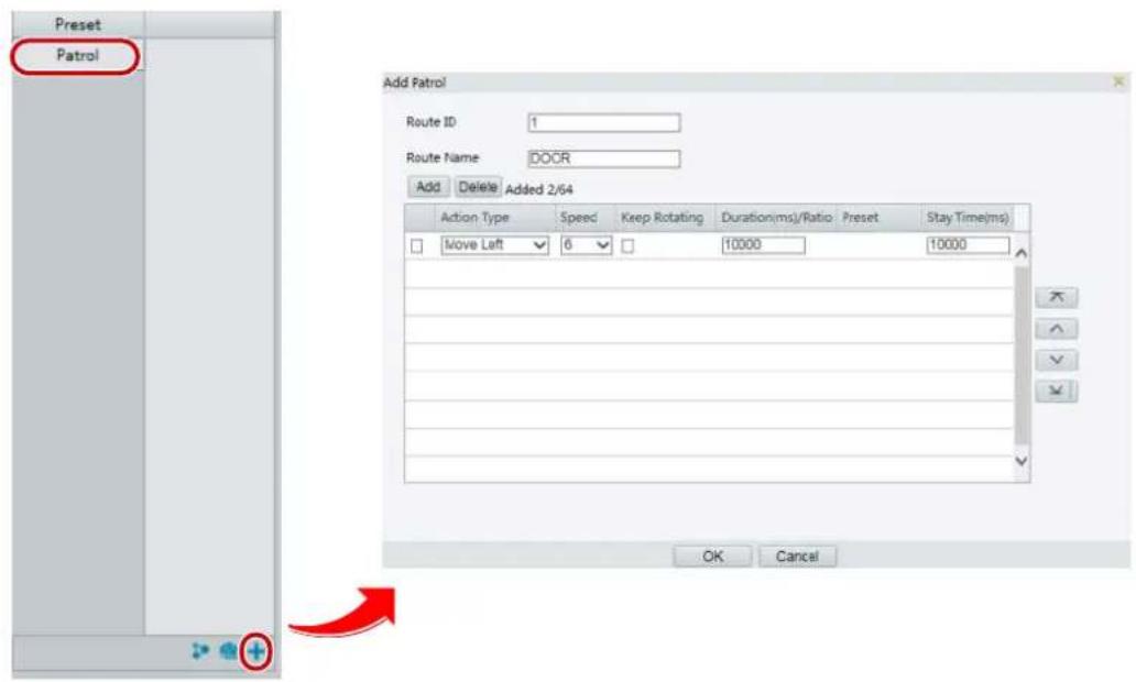
-
Click . +
-
On the Add Patrol page, enter the route ID and name, and then click Add to add a patrol action. Up to 64 actions are allowed. Each line includes two actions when action type is set to Move Direction and Zoom, so 32 actions are allowed. Use the buttons to adjust the sequence of the actions.
Patrol actions include:
- Go to a preset and stay for a certain amount of time before going to the next preset.
- Rotate at the set speed in the set direction for a certain amount of time, zoom, stay at a set position for a certain amount of time, or patrol repeatedly if Keep Rotating is selected.
It is recommended that the first action type is Go to Preset.
- Click OK.
Record a patrol route
- On the Live View page, click Patrol on the control panel.
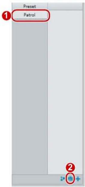
- Click 🔒 to start recording the patrol route. You can adjust the direction and zoom of the camera during the recording. The system records the motion and track of the camera and adds them to the action list.
- Click ■ to finish recording. Then the patrol route is saved as a mode route automatically. You can click ▶ to start patrol or to delete the mode route.
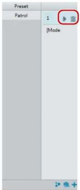
Make a patrol plan
- On the Live View page, click Patrol on the control panel.
![Preset Patrol 1 [DOOR] Patrol Plan Enable Patrol Plan Mon Tue Wed Thu Fri Sat Sun Please select Please select Please select Please select Please select Please select Please select Please select Please select Please select Copy Paste OK Cancel](/content/2026/05/958465/images/fc1a9ef2c0b3aa754ef2d4b9b11525d545e1e76656e539888c0e59cb5d575276.jpg)
- Click 📋. The page for setting patrol plans is displayed.
- Set the correct patrol time and route.
- Select Enable Patrol Plan.
- Click OK.
Start a patrol route
After you have added a patrol route, select the patrol route to start patrol.
- On the Live View page, click Patrol on the control panel.
![Prese① Patrol 1 [route1] ② 2 [route2]](/content/2026/05/958465/images/ba5b52dea7fd2241a31aa7e0676054f60bfa09d3149afa9fa4cf0fa05839b424.jpg)
- Click ▶ for the patrol route you want to start.
Edit a patrol route
- On the Live View page, click Patrol on the control panel.
![Preset 1 Patrol 2 1 [DOOR] Edit Route ID 1 Route Name DOOR Add Delete Action Type Speed Keep Rotating Duration(ms)/Ratio Preset Stay Time(ms) Move Left 6 10000 10000 OK Cancel](/content/2026/05/958465/images/c466408fa225a61526ec58f40b60c292d81eb8ca062f7bd3cc929d17538e5d7f.jpg)
- Click 📋 for the patrol route you want to edit and modify the settings as required.
Delete a patrol route
- On the Live View page, click Patrol on the control panel.
![Preset 1 Patrol 2 1 [DOOR]](/content/2026/05/958465/images/d60f71b7da6a099813315e3e2bf313bf6d4651f39c50efc12c769e496cf21bca.jpg)
- Click 📄 for the patrol route you want to delete and then confirm the delete.
Setting Home Position
PTZ camera will return to home position if no operation is made within a specified period.

NOTE!
- This function is available for network PTZ cameras only.
-
You need to add presets or a patrol route first. See Add a preset and Add a patrol route for details.
-
Click Setup>PTZ>Home Position.
![Home Position On Off Mode Preset ID 1[DOOR] Idle State(s) 60](/content/2026/05/958465/images/cd177072fd868270a22e087da65b21a4e76e241e9166c253d06ef5bf53538f89.jpg)
- Select a mode and ID.
- Click Save.
Remote Control PTZ
When the third-party platform is used and the PTZ protocol does not match that, you can set the remote control function to control the PTZ.

NOTE!
This function is only supported by PTZ cameras.
- Click Setup> PTZ> Remote Control.
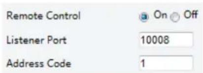
- Select On to enable Remote Control. Set the listener port and address code. The following table describes some major parameters.
| Acronym | Description |
| ListenerPort | Camera's local port, which cannot be a port that is already in use. Change the default setting only when necessary. |
| Address Code | The camera can read the address code contained in instructions. The camera interprets the instruction only when the address code in the instruction is the address code configured here. |
- Click Save.
PTZ Limit
Set rotation limits to prevent the PTZ camera from hitting obstacles such as a wall.

NOTE!
This function is only supported by some PTZ cameras.
- Click Setup>PTZ>PTZ Limit.
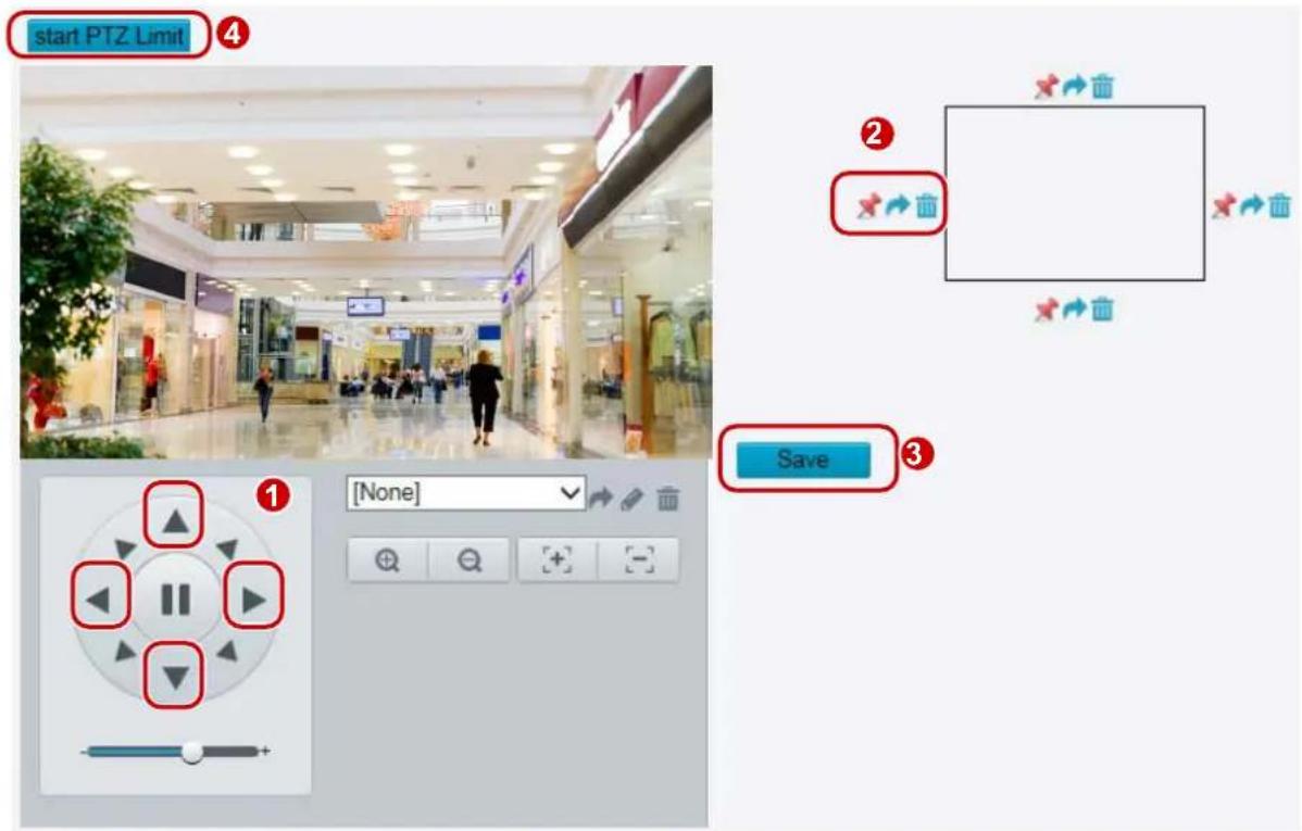
- Use directional buttons to rotate the camera to an intended position.
- Click ✗ to set the current position as a limit. For example, click ✗ on the top to set the upper limit.
Clicking will rotate the camera to the current position if the direction has been changed. - Repeat the above steps to set all limits as needed (up, down, left, right).
- Click Save.
- Click Start PTZ Limit to apply the setting.
- Click 📄 to delete settings and reset the limit.
Resume Patrol
- Click Setup> PTZ> Patrol.

- Set the time when patrol resumes.
- Click Save.

NOTE!
• This function is only available for certain models.
LPR Live View
- For cameras installed with Micro SD card, the snapshots will be saved to the SD card. If no SD card is installed, the snapshots will be saved to the PC. Click Open Image Folder to view snapshots. The close-up image of plate is displayed on the upper left pane.
- Click Clear All Records to clear snapshot records.
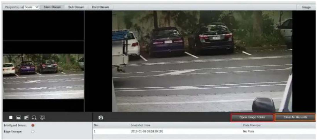
LPR Configuration
Draw Detection Area
- Click Setup > Intelligent> Traffic Monitoring. Click Draw Detection Rules.
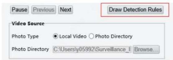
- Click Draw Detection Rules, and then draw a detection area on the snapshot.
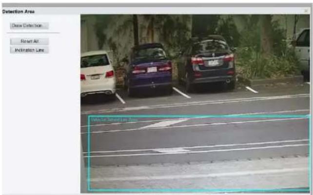
- Click Inclination Line, and then draw an inclination line that shows the inclination of the road surface.
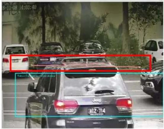
Reset Flow Counting
Click Setup>Intelligent>Traffic Monitoring>Smart>Reset Flow Counting. Set the time to reset LPR snapshot.
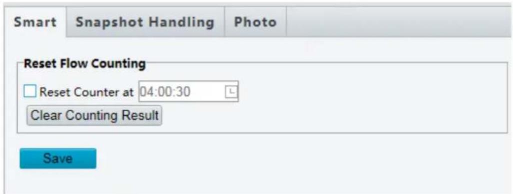
Smart-Snapshot Handling
Click Setup>Intelligent>Traffic Monitoring>Snapshot Handling. Usually the default settings are recommended.
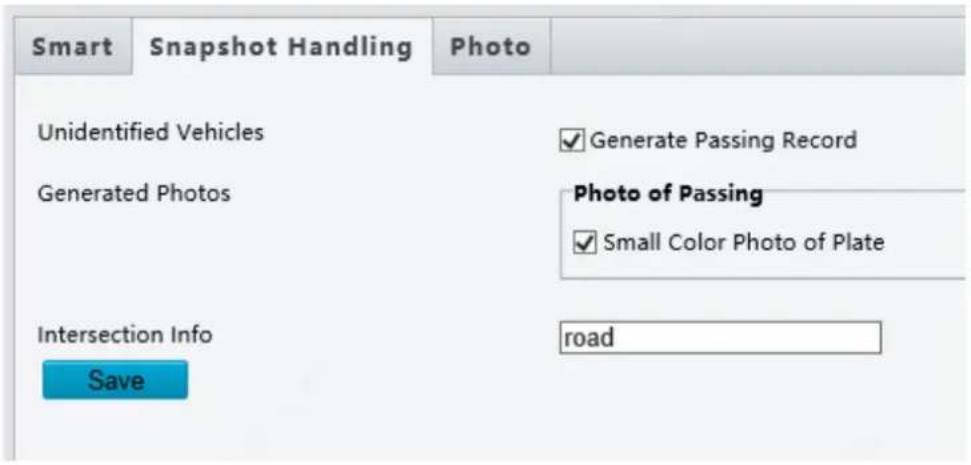
Unidentified Vehicles: Select whether to generate passing records for unidentified vehicles. This function is turned on by default.
Generated Photos: Select whether to display the close-up image of plate. By default the image is set to display.
Photo
Click Setup>Intelligent>Traffic Monitoring Photoshop. Configure snapshot OSD on this page.
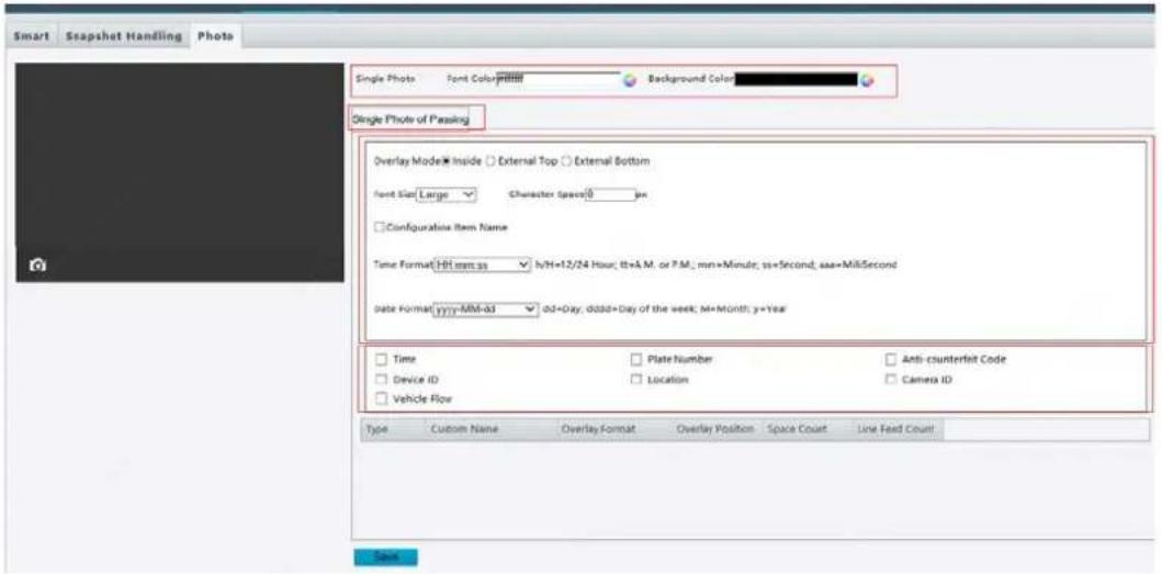
| Item | Description |
| Single Photo | Font color: OSD text color.Background color: OSD background color. |
| Font Size | Set the font size. |
| Character Space | Set the space between OSD characters. |
| Time Format | Set time format. |
| Date Format | Set date format. |
| OSD Items | Select OSD items.After selecting items, you can complete detailed OSD configuration for each item by editing in the table below. |
Appendix A Glossary
| Acronym | Description |
| ARP | Address Resolution Protocol |
| CBR | Constant Bit Rate |
| DNS | Domain Name Service |
| DDNS | Dynamic Domain Name Service |
| DHCP | Dynamic Host Configuration Protocol |
| DST | Daylight Saving Time |
| FTP | File Transfer Protocol |
| GOP | Group Of Pictures |
| GUI | Graphical User Interface |
| HTTPS | Hyper Text Transfer Protocol over SSL |
| IE | Internet Explorer |
| IMOS | IP Multimedia Operation System |
| IP | Internet Protocol |
| IPC | IP Camera |
| MTU | Maximum Transmission Unit |
| NTP | Network Time Protocol |
| OSD | On Screen Display |
| PoE | Power over Ethernet |
| PPPoE | Point-to-Point Protocol over Ethernet |
| PTZ | Pan, Tilt, Zoom |
| ROI | Region of Interest |
| SMTP | Simple Mail Transfer Protocol |
| SSL | Secure Socket Layer |
| UNP | Universal Network Passport |
| USB | Universal Serial Bus |
| VBR | Variable Bit Rate |
| WDR | Wide Dynamic Range |
Appendix B FAQ
What to do if no message prompts me to install ActiveX when I log in on a Windows 7 PC the first time
Answer: Follow these steps to turn off UAC and then log in again:
- Click the Start button, and then click Control Panel.
- In the search box, type uac, and then click Change User Account Control Settings.
- Move the slider to the Never Notify position, and then click OK.
- After UAC is turned off, log in again.
What to do if the installation of ActiveX failed
Answer: If the installation failed, add the IP address of the camera as a trusted site: open Internet Option in IE, click the Security tab, click Trusted sites, and then click Sites to add the website.
If you use Windows 7, you need to save the setup.exe to your PC first, right-click the file, select Run as administrator, and then install it according to instructions.
What to do if live video fails when I log in for the first time
Answer: Close the firewall on your PC and then log in to the Web interface again.
- Disclaimer
- CAUTION!
- Environmental Protection
- Symbols
- Contents
- Network Connection
- Login
- Preparation
- Check before login
- Add the IP address as a trusted site
- NOTE!
- (Optional) Modifyuser access control settings
- Logging In to the Web Interface
- Privacy Policy
- Privacy Policy of Uniview Technologies
- Introduction
- Scope of Information Collection
- Introduction to the Web Interface
- Initial Configuration
- Configuring Parameters
- Local Parameters
- Select Setup>Common>Local Parameters
- Click Save.
- Network Configuration
- Ethernet
- Static Address
- DHCP
- IPv6
- Wi-Fi
- Click Setup>Network>Port.
- FTP
- General
- Click Setup>Storage>FTP. Go to General tab.
- Smart
- Port Mapping
- DNS
- DDNS
- Click Setup>Network>P2P>Star4live.
- SNMP
- 802.1x
- QoS
- Click Setup > Network > QoS.
- Adaptive Streams
- Click Setup > Network > Wi-Fi, and set Wi-Fi Mode to Wi-Fi.
- Image Configuration
- Image Adjustment
- Setting the Scene
- Image Enhancement
- Click Setup>Image>Image and then click Image Enhancement.
- Exposure
- Click Setup>Image>Image and then click Smart Illumination.
- Select the correct IR control mode and set the parameters. The following table describes some major parameters.
- To restore the default settings, click Default.
- Focus
- Click Setup>Image>Image and then click Focus.
- Select the focus mode as required.
- White Balance
- Click Setup>Image>Image and then click White Balance.
- Select a white balance mode as required. The following table describes some major parameters.
- Advanced
- Click Setup>Image>Image and then click Advanced.
- Enable the defog function and then select a level for the scene. Level 9 achieves the maximum defog effects, and level 1 achieves the minimum.
- Lighting Type
- Click Setup>Image>Image and then click Smart Illumination
- Configuring Iris and Lens Mode
- Modify the settings as required. The following table describes some major parameters.
- OSD Setting
- Click Setup>Image>OSD.
- Privacy Mask
- Click Setup>Image>Privacy Mask.
- Audio and Video Configuration
- Video Configuration
- Click Setup>Video & Audio>Video.
- Audio Configuration
- Click Setup>Video & Audio>Audio.
- Snapshot
- Click Setup>Video & Audio>Snapshot.
- Media Stream Configuration
- Media Stream
- Click Setup>Video & Audio>Media Stream.
- RTSP Multicast Address
- Click Setup>Video & Audio>Media Stream>RTSP Multicast Address.
- Intelligent Alarm Configuration
- Cross Line Detection
- Enter Area
- Leave Area
- Intrusion Detection
- Click Setup >Intelligent>Smart. Choose Intrusion and then click
- Select Intrusion Detection.
- Object Moving
- Object Left
- Mixed -Traffic Detection
- Face
- Face Picture Comparison
- Add monitoring task.
- Click Setup >Intelligent>Smart. Choose People Counting and then click
- Auto Tracking
- Heat Map
- Defocus Detection
- Scene Change Detection
- Advanced Settings
- Photo parameters
- Master-Slave Linkage
- Attribute Collection
- Common Alarm Configuration
- Click Save.
- Configuring Motion Detection Alarm
- Area Detection
- Grid Detection
- Click Setup > Events > Motion Detection. Set Detection Mode to Grid.
- Configuring Tampering Alarm
- Configuring Audio Detection Alarm
- Configuring Alarm Input
- Click Setup>Events>Common Alarm >Alarm Input.
- Configuring Alarm Output
- Click Setup>Events>Common Alarm >Alarm Output.
- Memory Card Storage
- Manual storage
- Click Setup>Storage>Storage.
- Planned storage
- Setting Cache Post Recording
- Disable edge storage
- System Maintenance
- Security
- User Management
- Setting Secure Data Transmission
- Authentication
- Click Setup>Security> Network Security>Authentication.
- Hide Vendor Information
- Click Setup>Security> Registration Info.
- APR Protection
- IP Address Filtering
- ClickSetup>Security > Network Security>IP Address Filtering.
- Access Policy
- Click Setup> Security> Network Security> Access Policy.
- Watermark
- ClickSetup>Security>Watermark.
- Setting the System Time
- Manually Setting or Synchronizing the System Time
- Synchronizing with the NTP Server
- Setting the DST
- Setting Servers
- Intelligent Server
- Serial Port Mode Configuration
- PTZ control
- Transparent channel
- OSD
- ONVIF Transparent Channel
- Wiper Control
- Viewing Device Status
- Photo Storage Status
- Upgrading the Device
- Click Setup>System>Maintenance.
- Restarting the System
- Importing and Exporting System Configuration File
- Collecting Diagnosis Information
- Focus Configuration
- Device Mounting Height
- Fisheye Camera Parameter
- Live View
- Live View Toolbar
- Viewing Certain Area of Images
- Using Area Focus
- Using 3D Positioning
- Face Snapshot
- Click Clear All Records to clear the snapshots. Mixed-Traffic Detection Snapshot
- Live View of Fisheye Cameras
- 5ePTZ of Panoramic Cameras
- Video Playback and Download with Edge Storage
- Video Playback
- Download
- PTZ Control
- PTZ Control Toolbar
- Setting Patrol by Presets
- Setting Presets
- Add a preset
- Go to a preset
- Delete a preset
- Setting Patrol
- Add a patrol route
- Record a patrol route
- Make a patrol plan
- Start a patrol route
- Edit a patrol route
- Delete a patrol route
- Setting Home Position
- Remote Control PTZ
- PTZ Limit
- Resume Patrol
- LPR Live View
- LPR Configuration
- Draw Detection Area
- Reset Flow Counting
- Smart-Snapshot Handling
- Photo
- Appendix A Glossary
- Appendix B FAQ
Brand : i-PRO
Model : M-46-FW-V2
Category : Security Camera