
HDM-AVXWALLPLUS-4X10⁴C - Router Avenview - Free user manual and instructions
Find the device manual for free HDM-AVXWALLPLUS-4X10⁴C Avenview in PDF.


| Product Type | 4x10 HDMI Video Wall Processor / Router |
| Brand | Avenview |
| Model | HDM-AVXWALLPLUS-4X10⁴C |
| Form Factor | Rack-mountable 1U chassis |
| HDMI Inputs | 4 |
| HDMI Outputs | 10 |
| Max Resolution | 3840x2160 @ 60Hz (4K UHD) |
| Supported Video Wall Layouts | Customizable matrices up to 4x10, seamless scaling and switching |
| Control Interface | IR remote, RS232, Ethernet (TCP/IP), front panel buttons |
| Power Supply | AC 100-240V, 50/60Hz, internal power supply |
| Dimensions (W x D x H) | 17.0 x 10.0 x 1.75 inches (432 x 254 x 44 mm) |
| Weight | 7.5 lbs (3.4 kg) |
| Operating Temperature | 32°F to 104°F (0°C to 40°C) |
| Storage Temperature | -4°F to 140°F (-20°C to 60°C) |
| Humidity | 10% to 90% non-condensing |
| Warranty | 2 years limited warranty |
| Package Contents | Main unit, IR remote, RS232 cable, power cord, user manual |
| Cleaning Instructions | Wipe with a soft, dry cloth. Do not use liquids or sprays. |
| Safety Precautions | Keep away from water and moisture. Use only supplied power cord. Do not block vents. |
| Spare Parts & Repairability | No user-serviceable parts. Contact Avenview support for repairs or replacements. |
| Compliance | FCC, CE, RoHS |
Frequently Asked Questions - HDM-AVXWALLPLUS-4X10⁴C Avenview
User questions about HDM-AVXWALLPLUS-4X10⁴C Avenview
0 question about this device. Answer the ones you know or ask your own.
Ask a new question about this device
Download the instructions for your Router in PDF format for free! Find your manual HDM-AVXWALLPLUS-4X10⁴C - Avenview and take your electronic device back in hand. On this page are published all the documents necessary for the use of your device. HDM-AVXWALLPLUS-4X10⁴C by Avenview.
USER MANUAL HDM-AVXWALLPLUS-4X10⁴C Avenview
natural_image
Exterior view of multiple black Ultimate Video Wall Solution server racks (no signage or text beyond branding)Copyright
© 2018 Avenview Inc. All rights reserved.
The contents of this document are provided in connection with Avenview Inc. ("Avenview") products. Avenview makes no representations or warranties with respect to the accuracy or completeness of the contents of this publication and reserves the right to make changes to specifications and product descriptions at any time without notice. No license, whether express, implied, or otherwise, to any intellectual property rights is granted by this publication. Except as set forth in Avenview Standard Terms and Conditions of Sale, Avenview assumes no liability whatsoever, and disclaims any express or implied warranty, relating to its products of Avenview Inc. is strictly prohibited.
| Revision History | ||
| Rev. Changes Date | ||
| 0.00 Initial Release 02/01/2018 | ||
TABLE OF CONTENTS
I. GETTING STARTED....I
I.I IMPORTANT SAFEGUARDS....I
1.2 SAFETY INSTRUCTIONS......I
I.3 REGULATORY NOTICES FEDERAL COMMUNICATIONS COMMISSION (FCC)....2
2. INTRODUCTION....3
2.1 FEATURES....4
2.2 PACKAGE CONTENTS....5
2.3 BEFORE INSTALLATION....5
3. APPLICATION DIAGRAM....6
4. AVAILABLE CONFIGURATIONS....7
4.1 PANEL DESCRIPTION....7
4.1.1 I/O PANEL (CH4-2/4/10/16U, AVXWALL+)....7
4.1.2 I/O PANEL (CH3-10/16/28U, AVXWALL+)....8
4.2 INPUT CARDS....9
4.2.1 HDM-AVXWALLPLUS-4IN | HDMI 1.3....9
4.2.2 HDM4K-AVXWALLPLUS-2IN | HDMI 1.4a....9
4.2.3 DVI-AVXWALLPLUS-4IN | DVI SINGLE-LINK....9
4.2.4 DVIDL-AVXWALLPLUS-2IN | DVI DUAL-LINK....10
4.2.5 DP-AVXWALLPLUS-2IN | DISPLAYPORT I.1a....10
4.2.6 HBT-AVXWALLPLUS-4IN | HDBaseT....10
4.2.7 VGA-AVXWALLPLUS-4IN | VGA....II
4.2.8 COMP-AVXWALLPLUS-4IN | YPbPr....II
4.2.9 FOSC-AVXWALLPLUS-4IN | SC OPTICAL FIBER....II
4.2.10 FODL-AVXWALLPLUS-2IN | LC OPTICAL FIBER....12
4.2.11 SDI-AVXWALLPLUS-4IN | HD-SDI....12
4.2.12 CVBS-AVXWALLPLUS-4IN | CVBS....12
4.2.13 IP-AVXWALLPLUS-2IN | IP DECODE....13
4.2.14 OPT-AVXWALLPLUS-KVM|KVM SWITCH....13
4.2.15 AVXWALL+CONTROL CARD....13
TABLE OF CONTENTS
4.3 OUTPUT CARDS....14
4.3.1 HDM-AVXWALLPLUS-4OUT | HDMI 1.3....14
4.3.2 HDM4K-AVXWALLPLUS-2OUT | HDMI 1.4a....14
4.3.3 DVI-AVXWALLPLUS-4OUT | DVI SINGLE-LINK....14
4.3.4 DVIDL-AVXWALLPLUS-2OUT | DVI DUAL-LINK....15
4.3.5 DP-AVXWALLPLUS-2OUT | DISPLAYPORT I.Ia....15
4.3.6 HBT-AVXWALLPLUS-4OUT | HDBaseT....15
4.3.7 VGA-AVXWALLPLUS-4OUT | VGA....16
4.3.8 COMP-AVXWALLPLUS-4OUT | YPbPr....16
4.3.9 FOSC-AVXWALLPLUS-4OUT | SC OPTICAL FIBER....16
4.3.10 FODL-AVXWALLPLUS-2OUT | LC OPTICAL FIBER....17
4.3.11 SDI-AVXWALLPLUS-4OUT | HD-SDI....17
4.3.12 CVBS-AVXWALLPLUS-4OUT | CVBS....17
4.3.13 OPT-AVXWALLPLUS-CONF | CONFIDANCE MONITOR....18
5. INITIAL SETUP....18
5.1 INPUT/OUTPUT CARD INSTALLATION....19
5.2 CONFIGURATION....20
5.2.1 5.2.1- AVXWALL+ Controller Software....20
5.2.2 HBT-AVXWALLPLUS-4OUT | HDBaseT....20
5.2.3 VGA-AVXWALLPLUS-4OUT | VGA....20
6. SPECIFICATIONS....21
7. TROUBLESHOOTING TIPS....22
WARRANTY....23
I.1 IMPORTANT SAFEGUARDS
Please read all of these instructions carefully before you use the device. Save this manual for future reference.
Avenview warranty certificate please refer to page #23
Warranty does not include:
- Any product on which the serial number has been defaced, modified or removed.
• Damage, deterioration or malfunction resulting from: - Accident, misuse, neglect, fire, water, lightning, or other acts of nature, unauthorized product modification, or failure to follow instructions supplied with the product.
• Repair or attempted repair by anyone not authorized by us. - Any damage of the product due to shipment.
- Removal or installation of the product.
- Causes external to the product, such as electric power fluctuation or failure.
- Use of supplies or parts not meeting our specifications.
• Normal wear and tear. - Any other causes which does not relate to a product defect.
- Removal, installation, and set-up service charges.
1.2 SAFETY GUIDELINES
The AVXWALL-PLUS, 4K Modular Video Wall Processor has been tested for conformance to safety regulations and requirements, and has been certified for international use. However, like all electronic equipments, the AVXWALL+ should be used with care. Read the following safety instructions to protect yourself from possible injury and to minimize the risk of damage to the unit.
Do not dismantle the housing or modify the module.
Dismantling the housing or modifying the module may result in electrical shock or burn.
⚠️ Refer all servicing to qualified service personnel.
Do not attempt to service this product yourself as opening or removing housing may expose you to dangerous voltage or other hazards.
⚠️ Keep the device away from liquids.
Spillage onto the housing may result in fire, electrical shock, or equipment damage. If an object or liquid falls or spills on to the housing, unplug the module immediately.
If the unit appears damaged, have the module checked by a qualified service engineer before using it again.
Do not use liquid or aerosol cleaners to clean this unit. Always unplug the power to the device before cleaning.
1.3
REGULATORY NOTICES FEDERAL COMMUNICATIONS COMMISSION (FCC)
Note: This equipment has been tested and found to comply with the limits for a Class A digital device, pursuant to part 15 of the FCC Rules. These limits are designed to provide reasonable protection against harmful interference when the equipment is operated in a commercial environment. This equipment generates, uses, and can radiate radio frequency energy and, if not installed and used in accordance with the instruction manual, may cause harmful interference to radio communications. Operation of this equipment in a residential area is likely to cause harmful interference in which case the user will be required to correct the interference at his own expense.
Properly shielded and grounded cables and connectors must be used in order to meet FCC emission limits. Avenview is not responsible for any radio or television interference caused by using other than recommended cables and connectors or by unauthorized changes or modifications to this equipment.
| Warning Symbols | Description |
 | ONLY USE THE PROVIDED POWER CABIE OR POWER ADAPTER SUPPLIED. DO NOT TAMPER WITH THE ELECTRICAL PARTS. THIS MAY RESULT IN ELECTRICAL SHOCK OR BURN. |
 | THIS WARNING SYMBOL MEANS DANGER. WHEN THIS SYMBOL IS PLACED, YOU ARE IN AN ENVIRONMENT THAT CAN CAUSE BODILY INJURY. |
 | DO NOT TAMPER WITH THE UNIT. DOING SO WILL VOID THE WARRANTY AND CONTINUED USE OF THE PRODUCT. |
 | THE CIRCUIT BOARDS ARE VERY SENSITIVE TO STATIC DISCHARGE. PLEASE ENSURE IF RACK MOUNTED OR INSTALLED ON A SURFACE, IT SHOULD BE IN A GROUNDED ENVIRONMENT. |

natural_image
Blue circular icon with a white silhouette of a person holding a document (no text or symbols)⚠ WARNING
Read & understand user guide before using this device.
Failure to follow the proper installation instructions could result in damage to the product and preventing expected results.
2. INTRODUCTION
The AVXWALL + 4K Modular Video Wall Processor is the second generation of the Avenview modular video wall series. The modular AVX series hardware-based processors represent a range of FPGA modular chassis, with hot swappable Input /Output cards available in various media connections. Equipped with an advanced set of features such as keyboard, video, audio and mouse (KVM) control, Multi-User management and Multi-screen windowing, the unit provides fast and stable video wall control for any environment. Unlike PC based or software video walls, the AVX series is free from any virus or malware related security issues, making it ideal for high-quality 24/7 performance.
Flexible Input/Output Cards
The AVXWALL+ enables the user to insert the I/O cards into any available slot on the chassis thus offering the flexibility to customize their solution with an efficient, affordable and expandable hardware unit. The chipset on the I/O cards can endure high video bandwidth and process digital audio, resulting in real-time signal processing with no delay or frame loss. This unit can support two types resolutions on the Input /Output cards processing both analog and digital signals. The 4K resolution can distributed via HDMI, Displayport and Dual Link DVI cards. The Full HD resolution is delivered by CVBS, YPbPr, VGA, DVI, HDMI, SDI, DisplayPort, HDBaseT and Optical fiber cards. The AVXWALL+ offers two (2) newly featured input cards: the eight (8) port USB card allowing for KVM control and the IP decode card for decoding an RTP stream up to 1920x1080@60 over the LAN. Lastly, the additional Confidence monitoring output card has two HDMI output ports and RJ45 for RTP/H.264 1080p@60 decoding for recording, reviewing important content or distributing the entire video wall content to other remote locations.
Control Software Included
No in-depth training is required to use our AVX series, PC Control Software or iPad App, now enabled with multi user account creation and password management. This provides secure access for either managing via ADMIN rights or simple control for USER. Our software has comprehensive and user friendly features such as placing up to 16 images per screen, drag n drop image placement, resize, overlay, zoom, scrolling text, uploading large background images and user preset buttons to recall favorites. Our software can also preview the input source directly within the Control Software when connected through LAN network and enable or disable the audio on each output with easy to manage volume control slider function.
New Features
On Screen Mouse Control- connect a USB/Wireless mouse instead of using the PC software to control the inputs directly. With the mouse control user can: open and close windows, create up to nine windows on a single display, picture in picture (PIP), resize, and overlay. With the keyboard KVM Control feature any device with HID driver can be directly accessed, controlled and modified on the actual video wall with an attached Keyboard and Mouse. With the AVXWALL + you can manage 4 separate video walls simultaneously, recall the inputs and multi layouts on each video wall setup from a single PC or iPad interface. It also supports a 2x2, 3x3, and 4x4 – up to max 156 outputs on our largest 28U chassis.
2.1
FEATURES
- Modular input and output chassis design;
• Supports 4K 30Hz ultra high resolution image and high-quality P2P (Pixel to Pixel) screen resolution;
• High-performance system supports LCD, DLP and LED video wall of any size and layout;
- Users can insert input card, output card, and control card into any card slot;
- Users can control PC sources directly with mouse and keyboard;
- HD dynamic scrolling text function allowing users to define a group of scrolling text with different styles to publish messages and slogans;
• Supports analog/embed audio input and output allowing users to manage audio and video signals synchronically;
- On Screen Control, allows users to control the whole video wall using keyboard and mouse;
Users can open, resize, move and relocate input signals window without the need of any control software;
• Supports output image synchronization without row by row delay;
- Can manage up to 4 video wall groups with different resolution at the same time;
• Supports RS232 serial port and relay control interface for third part device control;
• Supports multi-user function allowing different users to login into the system and operate the processor at same time;
- Allows storage of up to 128 presets;
- Provides 60fps real-time mirroring high resolution video signal of the whole video wall (Confidence Monitoring) over HDMI or IP Stream;
• Supports CVBS, YPbPr, VGA, DVI, HDMI, SDI, DisplayPort, UTP and optical fiber;
• Full screen modes, zoom, image crop and adjustable size & position through software;
• Background Image storage;
• EDID Management;
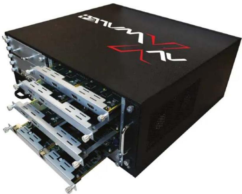
natural_image
Black server rack unit with red 'BATHM' and '7L' logo, showing internal circuit boards (no readable text beyond branding)2.2
PACKAGE CONTENTS
Before you start the installation of the AVXWALL-PLUS, please ensure that the packaging has the listed items below.
| # | ITEM | QTY | |
| 1 | AVXWALL-PLUSI/O CARDS INSTALLED | x1 |  |
| 2 | RACKMOUNT BRACKETS | x2 | [KDHB] |
| 3 | POWER CABLE | x1 |  |
| 4 | RJ-45 to DB9 SERIAL CABLE | x1 |  |
| 5 | CAT5e/6 PATCH CABLE | x1 | 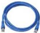 |
| 6 | PRODUCT USER MANUAL | x1 |  |
2.3
BEFORE INSTALLATION
ATTENTION
• To prevent airflow restriction, allow clearance around the ventilation openings to be at least: ONE Inch (25.4 mm)
• Take care when connecting units to the electrical power circuit so the maximum rated circuit is not overloaded
- Before you work on any equipment, be aware of the hazards involved with electrical circuitry
- Place the product on an even and stable surface. If the product falls, it may cause an injury to a person or malfunction.
- Do not place the product in high temperatures (over 50^ ), or low temperature (under 0^ ) or high humidity.
- Do not twist or pull by force ends of the UTP /HDMI cable. It can cause malfunction.
• Installation of the equipment must comply with local and national electrical codes.
3.
APPLICATION DIAGRAM


IP Decode Card (Optional)
Easily decode, capture and stream any RTP media with our IP Card in Full HD on to your active video wall.

KVM Control Card (Optional)
Capable of controlling up to seven (7) USB or HID compatible devices directly from the active video wall with a connected keyboard and mouse.

On Screen Mouse Control
Have the power of controlling the content on the active video wall using an easy click of the mouse - drag, resize, open, close, or arrange the layout.

Confidence Card (Optional)
View, record and stream your video wall content via the HDMI connection to the screen or RTP decoder port over the LAN network.

AVXWALL + Software
Powerful software that provides multi user management with different access levels and password protection. Now equipped with the standard feature to preview both the sources and the real-time video content, allowing the user to control any layout remotely over the network.

flowchart
graph TD
    A["User Device"] --> B["Network Switch"]
    B --> C["Confidence monitor"]
    C --> D["Remote laptop/PC"]
    D --> E["RTP H.264"]
    E --> F["Server or any usb compatible control device"]
    F --> G["Mouse control"]
    G --> H["Redundant power system: Sturdy 24/7 operation"]
    H --> I["Up to 15 types of hot-swappable I/O cards available"]
    I --> J["Terminal with X WALL logo"]
4.
AVAILABLE CONFIGURATIONS
| Chassis Model | # of I/O Card Slots | Max. # of Output Connections (HD/4K) | Max. # of Input Connections (HD/4K) | Dimensions (WxHxD) | Modular Cards |
| CH3-10U 9 | Input, 8 Output 36 / 18 36 / 18 440 x 442 x 380mm No | ||||
| CH3-16U 17 | Input, 17 Output 68 / 34 68 / 34 440 x 709 x 380mm No | ||||
| CH3-28U | 38 Input, 38 Output | 152 / 76 | 152 / 76 | 440 x 1242 x 380mm | No |
| CH4-2U | 4 | 12 / 6 | 12 / 6 | 440 x 89 x 380mm | Yes |
| CH4-4U | 8 | 28 / 14 | 28 / 14 | 440 x 175 x 380mm | Yes |
| CH4-10U | 17 | 64 / 22 64 / 22 | 440 x 442 x 380mm | Yes | |
| CH4-16U | 35 | 133 / 66 | 133 / 66 | 441 x 709 x 380mm | Yes |
4.1
PANEL DESCRIPTION
4.1.1 I/O PANEL (CH4-2/4/10/16U, AVXWALL+)

natural_image
Front view of a server rack with multiple ports and connectors, no visible text or labels| 1. Control Card: Power switch, USB, network control, RS232 in and out | 1. Power Supply: Replaceable |
| 3. Add-In Cards: IP Decode, KVM | 4. Input/Output Cards: HDMI, Display-Port, DVI, VGA, SDI, CVBS, Optical Fiber, VPbPr, HDBaseT, KVM, Confidence Monitor, IP Decode (RTP), |
4.1.2 I/O PANEL (CH3-10/16/28U, AVXWALL+)

| 1. Input Cards: 4K HDMI, DisplayPort, DVI, VGA, SDI, CVBS, Optical Fiber, VPbPr, HDBaseT, IP Decode (RTSP), KVM | 2. Fan Exhaust: Fan ventilation grating. Keep clear of obstructions |
| 3. Redundant Power Supply: Hot-swapable power delivery with fail-over protection | 4. Output Cards: 4K HDMI, DisplayPort, DVI, VGA, SDI, CVBS, Optical Fiber, VPbPr, HDBaseT, Confidence Monitor |
| 5. Control Card: Power switch, USB, network control, RS232 in and out |
4.2 INPUT CARDS
4.2.1 - HDM-AVXWALLPLUS-4IN | HDMI 1.3

natural_image
Front view of a network device chassis showing multiple Ethernet ports and indicator lights (no readable text or symbols)| Signal Format HDMI | 1.3 |
| Port Type 4x HDMI Type A | |
| Audio Support Embedded HDMI Audio | |
| Supported Resolutions | 800x600, 1024x768, 1280x720, 1280x800,1280x1024, 1360x768, 1366x768, 1400x1050,1440x900, 1600x1200, 1680x1050, 1920x1080, 1920x1200 |
| HDCP 1.4 | |
| EDID Support Read and Write | |
| Maximum Data Rate 4.95Gbps | |
natural_image
Front view of a white electronic device with two ports and two connectors (no visible text or symbols)| Signal Format HDMI | 1.4a |
| Port Type 2x HDMI | Type A |
| Audio Support Embedded HDMI Audio | |
| Supported Resolutions | 4096x2160@30Hz, 3840x2400@25Hz, 3840x2160@30Hz, 3840x2160@25Hz, 2560x1600@60, 1920x2160@60, 1920x2160@50, And lesser resolutions |
| HDCP 1.4 | |
| EDID Support Read and Write | |
| Maximum Data Rate 10.2Gbps | |
4.2.3- DVI-AVXWALLPLUS-4IN | DVI SINGLE-LINK

natural_image
Front view of a server rack with multiple connected VGA connectors and indicator lights (no visible text or labels)| Signal Format DVI 10 | |
| Port Type 4x DVI- | |
| Audio Support 3.5mm Jack (via Adapter Cable) | |
| Supported Resolutions | 800x600, 1024x768, 1280x720, 1280x800, 1280x1024, 1360x768, 1366x768, 1400x1050, 1440x900, 1600x1200, 1680x1050, 1920x1080, 1920x1200 |
| Color Depth 32bits/pixel | |
| Impedance | 50Ω |
*All resolutions have a framerate of 60Hz unless otherwise noted
4.2
INPUT CARDS (CONT)
4.2.4- DVIDL-AVXWALLPLUS-2IN | DVI DUAL-LINK

natural_image
Front panel of a network equipment unit showing two DVI and 2HDBI connectors with ports and indicators (no readable text beyond labels)| Signal Format DVI 1.0 | |
| Port Type 2x DVI-1 | Dual-Link |
| Audio Support 3.5mm Jack | |
| Supported Resolutions | 4096x2160@30Hz, 3840x2400@30Hz, 3840x2160@30Hz, 2560x1600@60Hz, And lesser resolutions |
| Color Depth 32bits/pixel | |
| Impedance 50Ω | |
4.2.5- DP-AVXWALLPLUS-2IN | DISPLAYPORT I.1a

natural_image
Front view of a white electronic device panel with two ports and two indicator lights (no visible text or symbols)| Signal Format Display Port 1.1a | |
| Port Type 2x Display Port | |
| Audio Support Embedded Display Port Audio | |
| Supported Resolutions | 4096x2160@30Hz, 3840x2400@30Hz, 3840x2160@30Hz, 2560x1600@60Hz, And lesser resolutions |
| HDCP 1.4 | |
| Maximum Data Rate 6. | 8Gbps |
4.2.6- HBT-AVXWALLPLUS-4IN | HDBaseT

natural_image
Front view of a network switch device with four Ethernet ports and labeled ports (no readable text beyond port numbers)| Signal Format | HDBaseT Video & Audio |
| Port Type | 4x RJ-45 |
| Audio Support | Embedded HDBaseT Audio |
| Supported Resolutions | 800x600, 1024x768, 1280x720, 1280x800, 1280x1024, 1360x768, 1366x768, 1400x1050, 1440x900, 1600x1200, 1680x1050, 1920x1080, 1920x1200 |
| Maximum Data Rate 10.2Gbps | |
4.2
INPUT CARDS (CONT)
4.2.7- VGA-AVXWALLPLUS-4IN | VGA

natural_image
Front panel of a network device showing multiple VGA connectors with indicator lights and ports (no readable text or symbols)| Signal Format RGBHV | |
| Port Type 4x DE-15 (VGA) | |
| Audio Support 3.5mm Jack | |
| Supported Resolutions | 800x600, 1024x768, 1280x720, 1280x800, 1280x1024, 1360x768, 1366x768, 1400x1050, 1440x900, 1600x1200, 1680x1050, 1920x1080, 1920x1200 |
4.2.8- COMP-AVXWALLPLUS-4IN | YPbPr

natural_image
Front panel of a computer interface with multiple VGA connectors and colored cables (no visible text or labels)| Signal Format YPbPr | |
| Port Type 4x 3-way RCA Jacks (via Adapter Cable) | |
| Audio Support 3.5mm Jack | |
| Supported Resolutions | 720x480i@60Hz, 720x576i@50Hz, 720x480p@60Hz, 720x576p@60Hz, 1280x720p@50Hz, 1280x720p@60Hz, 1920x1080i@60Hz, 1920x1080i@50Hz, 1920x1080p@25Hz, 1920x1080p@30Hz, 1920x1080p@50Hz, 1920x1080p@60Hz |
4.2.9- FOSC-AVXWALLPLUS-4IN | SC OPTICAL FIBER

natural_image
Front panel of a white electronic device with four black square buttons and two labeled ports (no readable text or symbols beyond labels)| Signal Format SC Optical Fiber | |
| Port Type SC Fiber | |
| Audio Support Embedded Audio | |
| Supported Resolutions | 800x600, 1024x768, 1280x720, 1280x800, 1280x1024, 1360x768, 1366x768, 1400x1050, 1440x900, 1600x1200, 1680x1050, 1920x1080, 1920x1200 |
4.2
INPUT CARDS (CONT)
4.2.10- FODL-AVXWALLPLUS-2IN | LC OPTICAL FIBER

natural_image
Front view of a white network device with two Ethernet ports and labeled ports (no readable text or symbols beyond labels)| Signal Format LC Optical Fiber | |
| Port Type LC Fiber | |
| Audio Support Embedded Audio | |
| Supported Resolutions | 800x600, 1024x768, 1280x720, 1280x800, 1280x1024, 1360x768, 1366x768, 1400x1050, 1440x900, 1600x1200, 1680x1050, 1920x1080, 1920x1200 |
4.2.11- SDI-AVXWALLPLUS-4IN | HD-SDI

natural_image
Front panel of a white electronic device with four metallic connectors and labeled ports (no readable text or symbols beyond component labels)| Signal Format 3G SDI | |
| Port Type BNC | |
| Audio Support Embedded Audio | |
| Supported Resolutions | 720x480i@60Hz, 720x576i@50Hz, 1280x720p@50Hz, 1280x720p@60Hz, 1920x1080p@24Hz, 1920x1080p@25Hz, 1920x1080p@30Hz, 1920x1080p@50Hz, 1920x1080p@60Hz, 1920x1080i@50Hz, 1920x1080i@60Hz |
4.2.12-CVBS-AVXWALLPLUS-4IN | CVBS

natural_image
Front panel of a white electronic device with four metallic circular connectors and two labeled ports (no readable text or symbols beyond labels)| Signal Format Composite Video |
| Port Type BNC |
| Audio Support 3.5mm Jack |
| Supported Resolutions 720x480i@60(NTSC),720x576i@50(PAL) |
4.2
INPUT CARDS (CONT)
4.2.13- IP-AVXWALLPLUS-2IN | IP DECODE

natural_image
Front view of a network device chassis with two Ethernet ports and labeled ports (no readable text or symbols beyond labels)| Signal Format RTSP | Stream |
| Port Type RJ-45 | |
| Audio Support Embedded Audio | |
| Supported Resolutions | DI,1280x720p@30,1280x960p@30,1920x1080p@30,1920x1080p@60 |
4.2.14- OPT-AVXWALLPLUS-KVM | KVM SWITCH

natural_image
Front panel of a network switch device showing eight ports (labeled 1–8) with C-RC and MANAGE branding, no readable text beyond labels.| Signal Format USB KVM | |
| Port Type USB Type B | |
| Features Keyboard and Mouse Control | |
| Supported OS | Windows, macOS, Linux |
4.2.15- AVXWALL+ CONTROL CARD

| Signal Format SYNC, RS232, TELNET, TCP/IP, USB, POWER | |
| Port Type BNC, 3x RJ-45, 2x USB Type A | |
| Features | RS232 In & Out, Telnet &,Mouse and Keyboard Control |
| Supported OS | Windows, macOS, Linux |
4.3
OUTPUT CARDS
4.3.1 - HDM-AVXWALLPLUS-4OUT | HDMI 1.3

natural_image
Front view of a network device chassis showing multiple Ethernet ports (no visible text or labels)| Signal Format HDMI | 1.3 |
| Port Type 4x HDMI Type A | |
| Audio Support Embedded HDMI Audio | |
| Supported Resolutions | 800x600, 1024x768, 1280x720, 1280x800, 1280x1024, 1360x768, 1366x768, 1400x1050, 1440x900, 1600x1200, 1680x1050, 1920x1080, 1920x1200 |
| HDCP 1.4 | |
| EDID Support Read and Write | |
| Maximum Data Rate 4.95Gbps | |
natural_image
Front view of a white electronic device with two Ethernet ports and two terminal connectors (no visible text or symbols)| Signal Format HDMI | 1.4a |
| Port Type 2x HDMI | Type A |
| Audio Support Embedded HDMI Audio | |
| Supported Resolutions | 4096x2160@30Hz, 3840x2400@25Hz, 3840x2160@30Hz, 3840x2160@25Hz, 2560x1600@60, 1920x2160@60, 1920x2160@50, And lesser resolutions |
| HDCP 1.4 | |
| EDID Support Read and Write | |
| Maximum Data Rate 10.2Gbps | |
4.3.3- DVI-AVXWALLPLUS-4OUT | DVI SINGLE-LINK

natural_image
Front view of a silver rack-mounted device with multiple DVI connectors and ports (no visible text or symbols)| Signal Format DVI 1.0 | |
| Port Type 4x DVI-1 | |
| Audio Support 3.5mm Jack (via Adapter Cable) | |
| Supported Resolutions | 800x600, 1024x768, 1280x720, 1280x800, 1280x1024, 1360x768, 1366x768, 1400x1050, 1440x900, 1600x1200, 1680x1050, 1920x1080, 1920x1200 |
| Color Depth 32bits/pixel | |
| Impedance | 50Ω |
4.3 OUTPUT CARDS (CONT)
4.3.4- DVIDL-AVXWALLPLUS-2OUT | DVI DUAL-LINK

natural_image
Front view of a network device rear panel showing DVI, I/O, and I/O ports with connectors (no readable text or symbols)| Signal Format DVI 1.0 | |
| Port Type 2x DVI-1 | Dual-Link |
| Audio Support 3.5mm Jack | |
| Supported Resolutions | 4096x2160@30Hz, 3840x2400@30Hz, 3840x2160@30Hz, 2560x1600@60Hz, And lesser resolutions |
| Color Depth 32bits/pixel | |
| Impedance 50Ω | |
4.3.5- DP-AVXWALLPLUS-2OUT | DISPLAYPORT I.Ia

natural_image
Front view of a white electronic device with two ports and indicator lights (no visible text or symbols)| Signal Format Display Port 1.1a | |
| Port Type 2x Display Port | |
| Audio Support Embedded Display Port Audio | |
| Supported Resolutions | 4096x2160@30Hz, 3840x2400@30Hz, 3840x2160@30Hz, 2560x1600@60Hz, And lesser resolutions |
| HDCP 1.4 | |
| Maximum Data Rate 6. | 8Gbps |
4.3.6- HBT-AVXWALLPLUS-4OUT | HDBaseT

natural_image
Front view of a network switch device with multiple Ethernet ports and ports labeled 1 to 4 (no readable text beyond labels)| Signal Format | HDBaseT Video & Audio |
| Port Type | 4x RJ-45 |
| Audio Support | Embedded HDBaseT Audio |
| Supported Resolutions | 800x600, 1024x768, 1280x720, 1280x800, 1280x1024, 1360x768, 1366x768, 1400x1050, 1440x900, 1600x1200, 1680x1050, 1920x1080, 1920x1200 |
| Maximum Data Rate 10.2Gbps | |
4.3 OUTPUT CARDS (CONT)
4.3.7- VGA-AVXWALLPLUS-4OUT | VGA

natural_image
Front panel of a network device showing multiple VGA connectors and ports (no visible text or labels)| Signal Format RGBHV | |
| Port Type 4x DE-15 (VGA) | |
| Audio Support 3.5mm Jack | |
| Supported Resolutions | 800x600, 1024x768, 1280x720, 1280x800, 1280x1024, 1360x768, 1366x768, 1400x1050, 1440x900, 1600x1200, 1680x1050, 1920x1080, 1920x1200 |
4.3.8- COMP-AVXWALLPLUS-4OUT | YPbPr

natural_image
Front panel of a network device showing multiple VGA connectors and ports (no readable text or symbols)| Signal Format YPbPr | |
| Port Type 4x 3-way RCA Jacks (via Adapter Cable) | |
| Audio Support 3.5mm Jack | |
| Supported Resolutions | 720x480i@60Hz, 720x576i@50Hz, 720x480p@60Hz, 720x576p@60Hz, 1280x720p@50Hz, 1280x720p@60Hz, 1920x1080i@60Hz, 1920x1080i@50Hz, 1920x1080p@25Hz, 1920x1080p@30Hz, 1920x1080p@50Hz, 1920x1080p@60Hz |
4.3.9- FOSC-AVXWALLPLUS-4OUT | SC OPTICAL FIBER

natural_image
Front panel of a white electronic device with four black square ports and two labeled ports (4UFO and OUTPUT), no readable text or symbols beyond labels.| Signal Format SC Optical Fiber | |
| Port Type SC Fiber | |
| Audio Support Embedded Audio | |
| Supported Resolutions | 800x600, 1024x768, 1280x720, 1280x800, 1280x1024, 1360x768, 1366x768, 1400x1050, 1440x900, 1600x1200, 1680x1050, 1920x1080, 1920x1200 |
4.3 OUTPUT CARDS (CONT)
4.2.10- FODL-AVXWALLPLUS-2OUT | LC OPTICAL FIBER

natural_image
Front view of a network device with two Ethernet ports and labeled ports (no readable text beyond labels)| Signal Format LC Optical Fiber | |
| Port Type LC Fiber | |
| Audio Support Embedded Audio | |
| Supported Resolutions | 800x600, 1024x768, 1280x720, 1280x800, 1280x1024, 1360x768, 1366x768, 1400x1050, 1440x900, 1600x1200, 1680x1050, 1920x1080, 1920x1200 |
4.2.11- SDI-AVXWALLPLUS-4OUT | HD-SDI

natural_image
Front panel of a white electronic device with four metallic connectors and labeled ports (no readable text beyond labels)| Signal Format 3G SDI | |
| Port Type BNC | |
| Audio Support Embedded Audio | |
| Supported Resolutions | 720x480i@60Hz, 720x576i@50Hz, 1280x720p@50Hz, 1280x720p@60Hz, 1920x1080p@24Hz, 1920x1080p@25Hz, 1920x1080p@30Hz, 1920x1080p@50Hz, 1920x1080p@60Hz, 1920x1080i@50Hz, 1920x1080i@60Hz |
4.2.12-CVBS-AVXWALLPLUS-4OUT | CVBS

natural_image
Front panel of a white electronic device with four metallic connectors and a 4W label (no readable text or symbols beyond branding)| Signal Format Composite Video |
| Port Type BNC |
| Audio Support 3.5mm Jack |
| Supported Resolutions 720x480i@60(NTSC),720x576i@50(PAL) |
4.3
OUTPUT CARDS (CONT)
4.2.13- OPT-AVXWALLPLUS-CONF | CONFIDANCE MONITO

natural_image
Front view of a silver network device with two Ethernet ports and two 2HX indicators (no readable text or symbols)| Signal Format H.264 | RTP, HDMI 1.3 |
| Port Type 1x RJ-45 | 2x HDMI Type A |
| Audio Support Embedded Audio | |
| Supported Resolutions | HDMI: 1920x1080p@60HzMain stream: RTP/ES/H.264, 1080p@60, 10Mbps;Sub stream: RTP/ES/H.264, D1(704x576p@60Hz), 4Mbps; |
5. INITIAL SETUP
To setup Avenview XXX-AVXWALL-PLUS follow the steps outlined below:
I. Premium quality DVI, HDMI, VGA, Composite, S-Video cables and adapters are recommended.
2. Make sure XXX-AVXWALL-PLUS is turned off.
3. Connect displays (or projectors, TV or other display devices) to output cards.
4. Connect the Source devices (such as, PC, DVD player, or Media player etc.) to input cards.
5. Connect a Windows based laptop or desktop (that will be used to configure the AVXWALL) to XXX-AVXWALL-PLUS using a CAT5e/6 Ethernet cable or RS-232 to USB Adapter cord.
6. Power ON XXX-AVXWALL-PLUS.
7. Turn ON all devices connected to AVXWALL and then setup the AVXWALL from the system through the AVWALL-PLUS software or TELNET.
DO NOT block the air vents of this device or stack another device on the top or bottom of the AVXWALL+. Blocking the air vents of the AVXWALL+ will cause the unit to overheat and will cause damage to your unit not covered under warranty
5.1
INPUT/OUTPUT CARD INSTALLATION
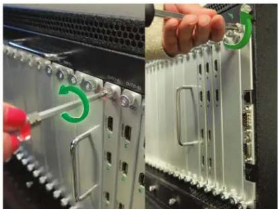
To remove an I/O card or the control card, follow these steps:
I. Obtain a Philips head screwdriver
2. Insert the screwdriver into the screw head as shown in the images below
3. Rotate the screwdriver in an anti-clockwise direction to loosen the screw

natural_image
Close-up of a server rack with attached hardware components, showing a hand adjusting a screwdriver (no visible text or symbols)
natural_image
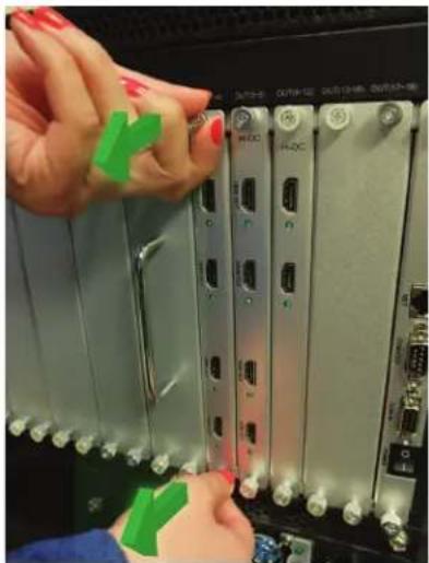
Close-up of a hand inserting a cable into a server rack with a green indicator light (no visible text or symbols)- With both screws loose, gently pull away from the unit
- The card will start sliding out of the chassis as shown in the photos below
natural_image
Close-up of hands installing or adjusting a network switch panel with ports labeled H-DC, H-DC, and various connectors (no readable text beyond labels)
natural_image
Close-up of hands installing a CD-ROM drive into a server rack (no visible text or labels)- To install an I/O card, perform the previous steps in reverse.
Note: Screws are attached to the card and can not be removed
5.2
CONFIGURATION
5.2.1- AVXWALL+ Controller Software
All features of the AVXWALL+ can be controlled through the AVXWALL+ Controller software. Your Windows-based computer connects to the unit through its RJ-45 network port either directly or through a network switch. More details on the AVXWALL+ Controller Software can be found in the Software Guide available HERE
Default IP Settings
IP Address: 192.168.1.65
Subnet: 255.255.255.0
Gateway: 192.168.1.1
Port: 2000

5.2.2- TELNET Control
All features of the AVXWALL+ can be controlled through the AVXWALL+ Telnet Command Line Interface. Your Windows-based computer connects to the unit through its RJ-45 network port either directly or through a network switch. More details on the AVXWALL+ Telnet Command Line can be found in the API Guide available HERE
5.2.3- RS232 Serial Control
All features of the AVXWALL+ can be controlled through the AVXWALL+ RS232 Serial Interface. Any serial enabled device can connect to the unit through the RJ-45 serial port. More details on the AVXWALL+ Serial Interface can be found in the API Guide available HERE
Default Serial Settings
Serial Line:
Speed: 9600
Data bits: 8
Stop bits: 1
Parity: None
Flow Control: None

6. SPECIFICATIONS
| CHASSIS | ||
| CHASSIS | 2U, 4U, 10U, 16U, 28U | |
| WEIGHT | According to size | |
| POWER | According to size, redundant power support | |
| SHOCKPROOF | ISTA IA | |
| COOLING | Multi-Fan | |
| INSTALLATION | 19-inch cabinet with mounting accessories | |
| OPERATING TEMPERATURE | 0°~40° - 32°F~104°F) | |
| STORAGE TEMPERATURE | -10°~60°(14°F~140°F) | |
| INPUT/OUTPUT | ||
| INPUT | DVI | Single-link DVI 1920x1200@60Hz; Dual-link DVI 3840x2400@30Hz |
| DISPLAYPORT 3840x2400@30Hz, 2560x1600@60Hz; downward compatibility; | ||
| HDMI 4K Resolution of HDMI 1.4 up to 3840x2160@30Hz;Embed audio | ||
| HDMI Resolution of HDMI 1.3 up to 1920x1080@60Hz; Embed audio | ||
| VGA Up to 1920x1200@60Hz; Audio interface 3.5mm | ||
| YPBPR Up to 1920x1080@60Hz; Audio interface 3.5mm | ||
| SDI Up to 1920x1080@60Hz; Support embed audio | ||
| IP Up to 1920x1080@60Hz; Support embed audio | ||
| CVBS PAL / NTSC; Audio interface 5 pin, unbalanced | ||
| HDBT Up to 1920x1200@60Hz; Support embed audio | ||
| FIBER Up to 1920x1200@60Hz; Support embed audio | ||
| OUTPUT | INTERFACE | DVI |
| VGA(via DVI-I) | ||
| HDBaseT | ||
| Fiber | ||
| CVBS | ||
| SDI | ||
| IP Stream | ||
| MIRRORING Supported (Confidence Monitoring) | ||
| RESOLUTION | 800x600, 1024x768, 1280x720, 1280x800, 1280x1024, 1360x768, 1366x768, 1440x900, 1440x1050, 1600x1200, 1680x1050, 1920x1080, 1920x1200, 2048x1080, 3840x2160, and Other Customized Resolutions | |
| AUDIO Supported on Select Cards | ||
| SCALE | INPUT SCALE Up to 152 ports (1080p) | |
| OUTPUT SCALE | Up to 152 ports | |
| SWITCHED BANDWIDTH | 160~1560 Gbps | |
7. TROUBLESHOOTING TIPS
| PROBLEM CORRECTIVE ACTION | |
| NO IMAGE | Check that the source is on and outputting a signalMake sure that each output and input is correctly connected to the corresponding deviceUse Premium Quality HDMI and DisplayPort cablesCheck output cards using test image in the AVXWALL+ Controller Software See Software Guide for more detailsCheck output cable for damage or if its length exceeds specifications |
| INCORRECT COLOR IN IMAGE | Check if the cable is connected properlyCheck if cable is damagedCheck software color adjustmentCheck display color adjustmentCheck if cables are securely connectedAdjust the color balance of the display |
| SHAKING OR NOISY IMAGE | Check cable length does not exceed specificationCheck cable quality |
| DARK EDGE IN DISPLAY IMAGE | Check if video signal has been cropped by the displayCheck if incorrect adjustment of the video has been made in the Controller softwareReset AVXWALL+ to default settings using Controller software, then reconfigure |
Avenview Warranty Certificate
AVENVIEW CORP. ("Avenview") warrants Avenview-branded product(s) contained in the original packaging against defects in materials and workmanship when used normally in accordance with Avenview's enclosed manual guidelines for a period of THREE (3) YEARS from the date of original retail purchase - Warranty Period. Avenview's published guidelines include but are not limited to information contained in technical specifications, user manuals and service communications.
LABOR: During the Warranty Period of THREE (3) YEARS, Avenview will repair or replace the product(s) at no cost using new or used parts equivalent to novel performance and reliability if the product(s) is determined to have able by Avenview's published guidelines. Cost of Labor applicable to product(s) after Warranty Period. For labor costs, please contact support@avenview.com.
PARTS: During the Warranty Period of 3THREE (3) YEARS, Avenview will supply new or rebuilt replacements in exchange for defective parts of the product(s) at no cost if the product(s) is determined to have abide by Avenview's published guidelines. Cost of Parts applicable to product(s) after Warranty Period. For part(s) costs, please contact support@avenview.com.
To obtain Warranty: (a) proof of purchase in the form of a bill of sale or received invoice reflecting that the registered product(s) is within warranty period must be presented to obtain warranty service; (b) product(s) must be registered at time of purchase. Failure to do so will result in applicable parts and labor charges. Returning product(s) must be shipped in Avenview's original packaging or in packaging pertaining equal degree of protection to Avenview's products. Both Avenview and purchaser are responsible for freight charges and brokerage fees when shipping the product(s) to the receiver.
NOT COVERED BY THIS WARRANTY
This warranty does not apply to any non-Avenview branded product(s), non-registered Avenview product(s). This warranty does not apply: (a) to cosmetic damage, including but not limited to scratches, dents and broken cords; (b) to damage caused by use with another product; (c) to damage caused by accident, abuse, misuse, liquid contact, fire, earthquake or other external cause; (d) to damage caused by operating the Avenview product(s) outside Avenview's manuals or guidelines; (e) to damage caused by service performed by anyone who is not a representative of Avenview or an Avenview authorized personnel; (f) to defects caused by normal wear and tear or otherwise due to the normal aging of the Avenview product(s), or (g) if any serial number or void stickers has been removed or defaced from the Avenview product(s).
AVENVIEW IS NOT LIABLE FOR DIRECT, SPECIAL, INCIDENTAL OR CONSEQUENTIAL DAMAGES RESULTING FROM ANY BREACH OF WARRANTY OR CONDITION, OR UNDER ANY OTHER LEGAL THEORY, INCLUDING BUT NOT LIMITED TO LOSS OF USE; LOSS OF REVENUE; LOSS OF ACTUAL OR ANTICIPATED PROFITS (INCLUDING LOSS OF PROFITS ON CONTRACTS); LOSS OF THE USE OF MONEY; LOSS OF ANTICIPATED SAVINGS; LOSS OF BUSINESS; LOSS OF OPPORTUNITY; LOSS OF GOODWILL; LOSS OF REPUTATION; LOSS OF DAMAGE TO COMPROMISE OR CORRUPTION OF DATA; OR ANY INDIRECT OR CONSEQUENTIAL LOSS OR DAMAGE REPAIR OR REPLACEMENT AS PROVIDED UNDER THIS WARRANTY IS THE EXCLUSIVE REMEDY OF THE CONSUMER.
Some states do not allow the inclusion or limitation of incidental or consequential damages, or allow limitations on duration implements of the Warranty Period; therefore the above limitations or exclusions may not be applicable to you. This warranty gives you specific legal rights, and you may have other rights which vary from state to state.

1100 Military Road, Kenmore, NY 14217 1.866.508.0269

TECHNICAL SUPPORT
CONTACT US

Phone: 1 (866) 508 0269

Email: support@avenview.com

natural_image
Illustration of a globe with headphones and a stylized ear, symbolizing global communication (no text or symbols present)Head Office Avenview Inc. 11-151 Esna Park Dr, Markham ON, L3R 3BI
Disclaimer
While every precaution has been taken in the preparation of this document, Avenview Inc. assumes no liability with respect to the operation or use of Avenview hardware, software or other products and documentation described herein, for any act or omission of Avenview concerning such products or this documentation, for any interruption of service, loss or interruption of business, loss of anticipatory profits, or for punitive, incidental or consequential damages in connection with the furnishing, performance, or use of the Avenview hardware, software, or other products and documentation provided herein.
Avenview Inc. reserves the right to make changes without further notice to a product or system described herein to improve reliability, function or design. With respect to Avenview products which this document relates, Avenview disclaims all express or implied warranties regarding such products, including but not limited to, the implied warranties of merchantability, fitness for a particular purpose, and non-infringement.


- Copyright
- TABLE OF CONTENTS
- OUTPUT CARDS....14
- INITIAL SETUP....18
- INPUT/OUTPUT CARD INSTALLATION....19
- CONFIGURATION....20
- SPECIFICATIONS....21
- TROUBLESHOOTING TIPS....22
- I.1 IMPORTANT SAFEGUARDS
- Warranty does not include:
- SAFETY GUIDELINES
- 1.3
- REGULATORY NOTICES FEDERAL COMMUNICATIONS COMMISSION (FCC)
- ⚠ WARNING
- INTRODUCTION
- Flexible Input/Output Cards
- Control Software Included
- New Features
- 2.1
- FEATURES
- 2.2
- PACKAGE CONTENTS
- 2.3
- BEFORE INSTALLATION
- ATTENTION
- APPLICATION DIAGRAM
- IP Decode Card (Optional)
- KVM Control Card (Optional)
- On Screen Mouse Control
- Confidence Card (Optional)
- AVXWALL + Software
- AVAILABLE CONFIGURATIONS
- PANEL DESCRIPTION
- I/O PANEL (CH4-2/4/10/16U, AVXWALL+)
- I/O PANEL (CH3-10/16/28U, AVXWALL+)
- INPUT CARDS
- - HDM-AVXWALLPLUS-4IN | HDMI 1.3
- 4.2.3- DVI-AVXWALLPLUS-4IN | DVI SINGLE-LINK
- 4.2
- INPUT CARDS (CONT)
- 4.2.4- DVIDL-AVXWALLPLUS-2IN | DVI DUAL-LINK
- 4.2.5- DP-AVXWALLPLUS-2IN | DISPLAYPORT I.1a
- 4.2.6- HBT-AVXWALLPLUS-4IN | HDBaseT
- 4.2.7- VGA-AVXWALLPLUS-4IN | VGA
- 4.2.8- COMP-AVXWALLPLUS-4IN | YPbPr
- 4.2.9- FOSC-AVXWALLPLUS-4IN | SC OPTICAL FIBER
- 4.2.10- FODL-AVXWALLPLUS-2IN | LC OPTICAL FIBER
- 4.2.11- SDI-AVXWALLPLUS-4IN | HD-SDI
- 4.2.12-CVBS-AVXWALLPLUS-4IN | CVBS
- 4.2.13- IP-AVXWALLPLUS-2IN | IP DECODE
- 4.2.14- OPT-AVXWALLPLUS-KVM | KVM SWITCH
- 4.2.15- AVXWALL+ CONTROL CARD
- 4.3
- OUTPUT CARDS
- - HDM-AVXWALLPLUS-4OUT | HDMI 1.3
- 4.3.3- DVI-AVXWALLPLUS-4OUT | DVI SINGLE-LINK
- OUTPUT CARDS (CONT)
- 4.3.4- DVIDL-AVXWALLPLUS-2OUT | DVI DUAL-LINK
- 4.3.5- DP-AVXWALLPLUS-2OUT | DISPLAYPORT I.Ia
- 4.3.6- HBT-AVXWALLPLUS-4OUT | HDBaseT
- 4.3.7- VGA-AVXWALLPLUS-4OUT | VGA
- 4.3.8- COMP-AVXWALLPLUS-4OUT | YPbPr
- 4.3.9- FOSC-AVXWALLPLUS-4OUT | SC OPTICAL FIBER
- 4.2.10- FODL-AVXWALLPLUS-2OUT | LC OPTICAL FIBER
- 4.2.11- SDI-AVXWALLPLUS-4OUT | HD-SDI
- 4.2.12-CVBS-AVXWALLPLUS-4OUT | CVBS
- OUTPUT CARDS (CONT)
- 4.2.13- OPT-AVXWALLPLUS-CONF | CONFIDANCE MONITO
- INITIAL SETUP
- 5.1
- INPUT/OUTPUT CARD INSTALLATION
- 5.2
- CONFIGURATION
- 5.2.1- AVXWALL+ Controller Software
- 5.2.2- TELNET Control
- 5.2.3- RS232 Serial Control
- SPECIFICATIONS
- TROUBLESHOOTING TIPS
- Avenview Warranty Certificate
- NOT COVERED BY THIS WARRANTY
- TECHNICAL SUPPORT
- CONTACT US
- Disclaimer
Brand : Avenview
Model : HDM-AVXWALLPLUS-4X10⁴C
Category : Router