
HDM-SWITCHPRO-VW4 - Router Avenview - Free user manual and instructions
Find the device manual for free HDM-SWITCHPRO-VW4 Avenview in PDF.


| Product Type | 4x4 HDMI Matrix Switcher with 2x2 Videowall Function & Audio |
| Brand | Avenview |
| Model | HDM-SWITCHPRO-VW4 |
| Dimensions (L x W x H) | 17.2" x 9.8" x 1.8" (437 x 249 x 46 mm) |
| Weight | 4.85 lbs (2.2 kg) |
| Power Supply | 12V DC, 3A (CE/FCC/UL certified adapter included) |
| Power Consumption | 36W (estimated from 12V/3A) |
| Input Ports | 4 x HDMI (19-pin female), 1 x RJ45 (Ethernet), 1 x RS-232 (D-sub 9-pin), 1 x Mini USB (service only) |
| Output Ports | 4 x HDMI (19-pin female) |
| Video Bandwidth | 225 MHz (6.75 Gbps) |
| Supported Input Resolutions | 480i/p, 576i/p, 720p, 1080i/p up to 60Hz; PC resolutions up to 1920x1200@60Hz |
| Supported Output Resolutions | 480p60, 576p50, 720p50/60, 1080i50/60 (Matrix only), 1080p24/50/60, PC up to 1920x1200@60RB |
| Audio Support | LPCM 2/6/8CH, AC3, DTS, Dolby Digital Plus, Dolby TrueHD, DTS-HD |
| Control Methods | Front panel buttons, IR remote, RS-232, Telnet (Ethernet), Web GUI |
| Operating Modes | Matrix (4x4), Splitter (1 to 4), Dual-Viewer (PAP), 2x2 Videowall, Quad (4 in 1) |
| HDCP Compliance | Yes |
| Videowall Function | 2x2 with bezel correction for seamless alignment |
| Operating Temperature | 32°F to 104°F (0°C to 40°C) |
| Storage Temperature | -4°F to 140°F (-20°C to 60°C) |
| Warranty | 3 years (parts and labor) |
| Package Contents | Unit, power adapter, IR remote, CD (optional), user manual |
Frequently Asked Questions - HDM-SWITCHPRO-VW4 Avenview
User questions about HDM-SWITCHPRO-VW4 Avenview
0 question about this device. Answer the ones you know or ask your own.
Ask a new question about this device
Download the instructions for your Router in PDF format for free! Find your manual HDM-SWITCHPRO-VW4 - Avenview and take your electronic device back in hand. On this page are published all the documents necessary for the use of your device. HDM-SWITCHPRO-VW4 by Avenview.
USER MANUAL HDM-SWITCHPRO-VW4 Avenview
HDMI Matrix Switcher with 2x2 Videowall function & Audio







Model #: HDM-SWITCHPRO-VW4
Product Application & Market Sectors

Corporate

House Of Worship

Military Residenti


Education Industry


Medical Aviation

TABLE OF CONTENTS
I. GETTING STARTED .... I
I.1 IMPORTANT SAFEGUARDS....I
1.2 SAFETY INSTRUCTIONS ...... I
1.3 REGULATORY NOTICES FEDERAL COMMUNICATIONS COMMISSION (FCC) 2
2. INTRODUCTION....3
2.1 PACKAGE CONTENTS 4
2.2. BEFORE INSTALLATION....5
2.3 APPLICATION DIAGRAM....6
3. PANEL DESCRIPTION....8
3.1 Control Panel Front 8
3.2 Input Panel Rear 9
- IR REMOTE CONTROL....10
4.1 INSTALLATION....II
4.1 Hardware Setup....
4.2 Control Software ...... 11
4.3 Software Setup Guide ...... 11
- GUI (SOFTWARE INTERFACE)....13
5.1 Simple Control Panel....13
5.2 Advance Control Panel....13
- SPECIFICATIONS....14
- INPUT/OUTPUT SUPPORT TIMING 15
7.1 Input Support Timing 15
7.2 Output Support Timing....15
I.1 IMPORTANT SAFEGUARDS
Please read all of these instructions carefully before you use the Fiber Optic cable. Save this manual for future reference.
What the warranty does not cover
- Any product, on which the serial number has been defaced, modified or removed.
• Damage, deterioration or malfunction resulting from: - Accident, misuse, neglect, fire, water, lightning, or other acts of nature, unauthorized product modification, or failure to follow instructions supplied with the product.
• Repair or attempted repair by anyone not authorized by us.
• Any damage of the product due to shipment. - Removal or installation of the product.
- Causes external to the product, such as electric power fluctuation or failure.
• Use of supplies or parts not meeting our specifications.
• Normal wear and tear.
• Any other causes which does not relate to a product defect. - Removal, installation, and set-up service charges.
1.2 SAFETY INSTRUCTIONS
The HDM-SWITCHPRO-VW4, HDMI Matrix Switcher with Videowall and audio has been tested for conformance to safety regulations and requirements, and has been certified for international use. However, like all electronic equipments, the HDM-SWITCHPRO-VW4 should be used with care. Read the following safety instructions to protect yourself from possible injury and to minimize the risk of damage to the unit.
Do not dismantle the housing or modify the module.
Dismantling the housing or modifying the module may result in electrical shock or burn.
⚠️ Refer all servicing to qualified service personnel.
Do not attempt to service this product yourself as opening or removing housing may expose you to dangerous voltage or other hazards
Keep the module away from liquids.
⚠️ Spillage into the housing may result in fire, electrical shock, or equipment damage. If an object or liquid falls or spills on to the housing, unplug the module immediately.
Have the module checked by a qualified service engineer before using it again.
Do not use liquid or aerosol cleaners to clean this unit. Always unplug the power to the device before cleaning.
1.3
REGULATORY NOTICES FEDERAL COMMUNICATIONS COMMISSION (FCC)
This equipment has been tested and found to comply with Part 15 of the FCC rules. These limits are designed to provide reasonable protection against harmful interference in a residential installation.
Any changes or modifications made to this equipment may void the user's authority to operate this equipment.
Warning symbols Description

ONLY USE THE PROVIDED POWER CABLE OR POWER ADAPTER SUPPLIED. DO NOT TAMPER WITH THE ELECTRICAL PARTS. THIS MAY RESULT IN ELECTRICAL SHOCK OR BURN.

DO NOT TAMPER WITH THE UNIT. DOING SO WILL VOID THE WARRANTY AND CONTINUED USE OF THE PRODUCT.


BEWARE
this unit
contains
static
sensitive devices
THE VIDEO BOARDS ARE VERY SENSITIVE TO STATIC. PLEASE ENSURE IF RACK MOUNTED OR INSTALLED ON A SURFACE, IT SHOULD BE IN A GROUNDED ENVIROMENT.

natural_image
Blue circular icon with a white silhouette of a person holding an open book (no text or symbols)WARNING
Read & understand user guide before using this device.
Failure to follow the proper installation instructions could result in damage to the product and preventing expected results.
2. INTRODUCTION
This unique powerful processor was developed for the growing demand in the digital market which has made 2x2 Videowall advertising become an industry standard in marketing.
This small form factor HDMI device can perform many functions such as;
4x4 Matrix switcher – This device can input 4 HDMI digital sources and then distribute the video and audio signal to any 4 HDMI HD Monitors. Supported video timings up to 1080p@60Hz Full HD and WUXGA Wide 1920x1200 audio formats up to 7.1CH LPCM AT 192Hz. This device can be configured using the IR Remote, Telnet, Rs232 or Front Panel buttons to set the desired I-4 output sources. Bonus feature of this device, while in Matrix mode the switching is seamless between the sources NO Delay
Multi Input Splitter – This device can input 4 HDMI digital sources and then duplicate one source at once to the connected 4 HDMI HD Monitors. This device can be configured using the IR Remote, Telnet, Rs232 or Front Panel buttons to set the desired output source.
Dual-Viewer – This device can input 4 HDMI digital sources and then combine, (4) four video signals onto two HD Monitors at Full HD 1080p. This device can be configured using the IR Remote, Telnet, Rs232 or Front Panel buttons to set the desired PAP (Picture Aside Picture).
Videowall 2x2 – This device can input 4 HDMI digital sources and scale (1) one Input across the (4) four HD monitors in a 2x2 configuration at Full HD 1080p. This device can be configured using the IR Remote, Telnet, Rs232 or Front Panel buttons to set the desired video across the (4) four HD Monitors with Bezel Correction to align the image seamlessly.
- Input resolution settings from PC -VGA, XGA (1024 x 768), SXGA (1280 x 1024), UXGA (1600 x 1200), WUXGA (1920 x 1200)
- Input resolution settings from Digital Player- 480p up to Full HD 1080p (1920 x 1080);
- Output Resolutions from 480p to 1080p Deep Color 8/10/12 bit source
- Audio Supports LPCM 2CH, 6CH, 8CH/AC3/DTS/Dolby Digital Plus/Dolby TruHD & DTS-HD
- Fine tuning and adjustments of contrast, brightness, Saturation and hue;
- Dual Mode Feature: Display POP (Picture over Picture) & PIP (Picture in Picture) image combined by 2 Sources;
- Quad Mode Feature: Output all input sources as a full image to a single display (4 in 1),
- Preset up to 4 favorite layout options;
- Auto EDID detect from the source;
- Bezel Correction support for 2x2 Videowall Mode;
- USB for Service Mode and Firmware upgrade;
- Connection by IR Remote, Telnet or Rs232 for user setup and configuration;
- HDMI, HDCP and DVI Compliant;
- Also supports Web-GUI control (use the unit's IP address in IE or other browsers and this will allow the user to control the unit remotely) User can get IP from OSD Menu → Ethernet or use RS232 command "Get IP"
- Factory Reset;
2.1 PACKAGE CONTENTS
Before you start the installation of the converter, please check the package contents.
| 1 | HDM-SWITCHPRO-VW4 X I |  | |
| 2 | Power Supply (12V 3A) X I |  | |
| 3 | IR Remote X I |  | |
| 4 | CD (Optional) Download Available X I |  | |
| 5 | User's Manual X I |  | |
2.2. BEFORE INSTALLATION
- Put the product in an even and stable location. If the product falls down or drops, it may cause an injury or malfunction.
- Don't place the product in too high temperature (over 50^ ), too low temperature (under 0^ ) or high humidity.
- Use the DC power adapter with correct specifications. If inappropriate power supply is used then it may cause a fire.
- Do not twist or pull by force ends of the video cable. It can cause malfunction.
Device Layout Functions
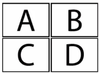

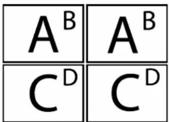

HDM-SWITCHPRO-VW4
CABLE INDEX
Output
Input / Source
FULL HORIZOP (WACKBOX) = 10m (25 sec) HDMI
WUXGA(150/0X1200) = 10m (33 feet) HDMI
PICTURE IN PICTURE FUNCTION
LAYOUT 1
HD Monitor 1
HD Monitor 2

natural_image
Red and black racing cars competing on a track at an outdoor event (no visible text or symbols)
natural_image
Colorful striped fish swimming in blue water with coral branches in the background (no text or symbols)
natural_image
Astronaut performing spacewalk outside spacecraft, with Earth visible in background (no text or symbols)
natural_image
Action photo of a motorcyclist on a dirt track under a blue sky (no text or symbols visible)HD Monitor 3
HD Murder 4

flowchart
graph TD
    A["Overview"] --> B["HDM Source 1"]
    A --> C["HDM Source 2"]
    A --> D["HDM Source 3"]
    A --> E["HDM Source 4"]
    B --> F["PC Control Software RS-232, Telecom, TCP/IP"]
    C --> F
    D --> F
    E --> F
    F --> G["Back"]
    G --> H["Hardware Icon"]
    H --> I["Computer"]

3. PANEL DESCRIPTION
3.1 Control Panel Front
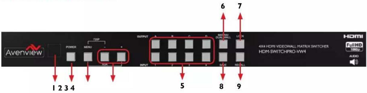
| 1. IR Window: Receives IR signals from the device remote control (Included in package) | 2. Power Button: Toggle ON/OFFFirst Press Power OnSecond Press Standby Mode.Note : Quick Factory ResetHOLD power button then connect power supply to the unit. |
| 3. Menu Button : Shows the OSD Menu on the screenMenu with “-” button : switches the output timing to 720@60HzMenu with “+” button : switches the output timing to XGA (1024x768@60Hz) | 4. -/+ Buttons : To scroll down and up in the OSD Menu to confirm the selection “Press Menu Button” |
| 5. Input IN I- IN 4 /Output OUTI- OUT4 : Refer to Section below NO.5 | 6. Matrix/Dual/2x2 Button:Toggle between the different modes |
| 7. LOCK: Press once to lock the keypad and the remote control. To deactivate lock function press for 3 sec. | 8. SAVE: To save the user customized input and output settings |
| 9. RECALL: During the operation of Matrix/Dual/2x2, press “RECALL” and the input channel I-4 LED will illuminate at once , select input channel 1/2/3 or 4 to recall the customized screen settings and this will correspond to buttons on the remote control FAV-I to FAV-4. | |
NO.5: Input IN I-IN 4 /Output OUTI-OUT4
MATRIX MODE
Press Matrix /Dual/2x2 button to switch to Matrix mode and LED will illuminate steady.
To choose OUTPUT OUT1-OUT4 press the corresponding Input IN I - IN4
Example: 1 ^st Press OUT I 2 ^nd Press IN I the HD monitor attached to OUT I will display IN I image.
DUAL MODE
Press Matrix /Dual/2x2 button to switch to Dual mode and LED will illuminate steady.
Choose the output OUT1/OUT2 and then the Input IN1/IN2
Example: Press OUTI then press INI - result OUTI will display INI image on the left side
Press OUT2 then press IN2 – result OUT1 will display IN2 image on the right side
The (2) two HD monitors connected to OUT1/2 will now show two images on each monitor in a PAP (Picture aside Picture) format.
Dual A group are output OUT1 and OUT2, Dual B group are output OUT3 and OUT4.
Each group will output the same image simultaneously.
AUDIO
Press button OUT1 or OUT2 for 3 seconds, to switch DUAL A channel's audio between outputs OUT1 or OUT2. Press button OUT3 or OUT4 for 3 seconds, to switch DUAL B channel's audio between outputs OUT3 or OUT4.
2x2 VIDEOWALL MODE
Press Matrix /Dual/2x2 button to switch to 2x2 mode and LED will illuminate steady.
Press input INI-IN4 to select a source to display across all four Monitors in a 2x2 Videowall configuration. The audio will be on output OUT1 only.
NO.8: SAVE
CUSTOMIZED INPUT AND OUTPUT SETTINGS
Press Matrix/Dual/2x2 button to select the function required.
Press each output channel OUT1-OUT4 and then press the corresponding input channel IN1-IN 4.
SAVE INPUT
Press "SAVE", the input I-4 LEDs will illuminate, all at the same time.
Proceed to select the input 1/2/3 or 4 to save to the systems memory.
Example: Select Matrix mode, press output OUT1 then press input IN4, then press "SAVE".
This will correspond to remote control FAV-I-FAV 4.
3.2 Input Panel Rear

| 1. HDMI IN 1-4: Connect up to 4 HDMI deceives to the INPUT ports 1-4 (Blu-ray or PC) | 2. HDMI OUT 1-4: Connect up to 4 HDMI HD Monitor/Displays to view inputs connected. |
| 3. Ethernet Control: Connect RJ45 jack to an active network for Telnet control Please download codes from WEBSITE | 4. USB Service Only: This port is reserved for factory use only. |
| 5. RS-232: D-Sub 9-pin port for sending and controlling the unit by PC/Notebook via RS232 cable. | 6. DC 12V: Plug the 12V DC power supply into the unit supplied to an AC 110v Outlet. |
4. IR REMOTE CONTROL
I. POWER BUTTON: 1 ^st Press Power on the device / 2 ^nd Press - Standby mode.
-
INFO BUTTON: To show device firmware version
-
OUT1\~OUT4 and IN 1\~IN 4: 1 ^st Press output 1\~4 2 ^nd Press input 1\~4 to select display input. Example: Press OUT1 then Press IN1, OUT1 will display Input's image.
-
MATRIX/DUAL/2x2: Toggle between Matrix mode, Dual mode and 2x2 mode.
-
LOCK BUTTON: 1 ^st Press to lock the keypad and remote control, 2 ^nd Press for 3 second release the lock function.
-
MUTE BUTTON: To mute the audio from the HDMI output ports.
-
NAVIGATION BUTTONS: -▲/▼/←/→/OK to scroll through the OSD MENU. OK to Enter or confirm the settings.
-
EXIT BUTTON: To exit the OSD menu or OSD settings.
-
MENU BUTTON: To access the OSD menu.
-
HOTKEYS BUTTONS: 1024x768/720p/1080p to quickly switch between resolutions.
-
HOT KEYS BUTTONS AL/AR/BL/BR: In Dual mode, press these buttons to switch the audio channel Left or Right side for Dual A and Dual B group.
-
SAVE BUTTON: To save the user customized input and output corresponding settings.
REMOTE CONTROL DIP SWITCH
Open the IR Remote control back cover to adjust dip-switch UP- ON/ DOWN - OFF to match IR address settings in the OSD (On Screen Display) menu. Factory default is on 0.

4.1 Hardware Setup
To setup Avenview HDM-SWITCHPRO-VW4 follow these steps below:
I. Mount or fix the HDM-SWITCHPRO-VW4 on a secure shelf, AV rack or steady surface;
2. Ensure the power is off on the HDM-SWITCHPRO-VW4, all source devices and displays that will be connected;
3. Connect your (4) four HDMI cables to the (4) four HDMI sources such as (Blu-ray Player, Laptop or Set-Top-Box or Gaming device);
4. Connect your (4) four HDMI cables to the (4) four HD Displays, LCD or PC Monitors that is receiving the video signals.
5. Power on all devices.
6. Connect your computer to HDM-SWITCHPRO-VW4 via RS232, RS-232 to USB or Ethernet cable and then proceed to section 4.2 Control Software.
4.2 Control Software
The HDM-SWITCHPRO-VW4 can be controlled via Windows based Laptop/PC by installing the software HDM-SWITCHPRO-VW4-1.5.Control software can be downloaded from Avenview website under the product part number HDM-SWITCHPRO-VW4>download/software section
GENERAL INSTRUCTIONS
- Before you begin the installation of the control software ensure the HDM-SWITCHPRO-VW4 is connected to AC power and your PC via RS-232, USB to RS-232 or Ethernet Patch Cord PC Requirements-Windows® XP/Windows Vista®/Windows® 7/Windows® 8
- Ensure the Laptop/PC is plugged in to AC power during the installation process. It is not recommended to use only battery power during the installation. Do not remove power at any time during the installation process as this could lead to incomplete results.
4.3 Software Setup Guide
Please ensure the communication cables (RS-232, RS-232 to USB, Ethernet) are properly seated and the drivers for the RS-232 to USB are installed before and confirmed communication in the Device Manager before proceeding.
| RS-232 SETTINGS | Baud Rate: 115200bpsData Bit: 8 bitsParity: NoneFlow Control: NoneStop Bit: 1 |
To connect to the HDM-SWITCHPRO-VW4 please choose any of the (2) two convenient methods by selecting the connection tab and confirming the method.
| TYPE OF CONNECTION PORT CONFIGURATION | |
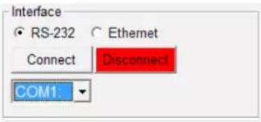 | - RS2321. Choose the correct COM port (verify from PC device manager).2. Press Connect.Connection Successful – The connect button will be green. If not, a popup window -Error message “COM # Fail!” |
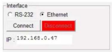  | - TCP/IP1. Choose Ethernet (verify from Network Support an assigned IP address or Press GET IP from control software).2. Press Connect.Connection Successful - The connect button will be green. If not, a popup window -Error message “Could not find Server!” |
5. GUI (SOFTWARE INTERFACE)
This unit can be controlled via PC with Control Software or Hyper Terminal to configure the settings. See the additional documentation for control codes for download via Website.
5.1 Simple Control Panel

5.2 Advance Control Panel

5.1 WEB GUI (GRAPHICAL USER INTERFACE)
Connect the HDM-SWITCHPRO-VW4 -CONTROL port from an active network service with RJ-45 terminated CAT5e/6 cable and open a web browser from a PC/laptop with device's IP address on the web address entry bar then hit enter. The browser will display device's Picture, Output Resolution, Audio, OSD Settings, HDCP, BEZEL Correction and Ethernet setting pages.
Note: Power Status must set to ON and Source status must be unlock in order to set the setting accordingly

Easily select any user defined function within the WEB GUI interface. Convenient and quick response over the Internet, just as making changes locally connected to the unit via RS232.
ETHERNET TAB
Users can select this TAB to change or set IP configuration settings. Note: If any changes are made within this TAB, the device (from the OSD setting menu) and the IP web address has to be reset to concur with the changes.

6.
SPECIFICATIONS
| Item Description | ||
| UNITS HDM-SWITCHPRO-VW4 | ||
| UNIT DESCRIPTION 4x4 Matrix | Switch with 2x2 Videowall Function with Audio | |
| HDCP COMPLIANCE Yes | ||
| VIDEO BANDWIDTH 225 MHz | (6.75Gbps) | |
| SUPPORTED RESOLUTIONS Refer to section 7 on the User Guide | ||
| AUDIO SUPPORT LPCM 2CH, 6CH, 8CH/AC3/DTS/Dolby Digital Plus/Dolby TruHD & DTS-HD | ||
| INPUT | 4 x HDMI19 Pin Female type connector | 1 x RJ45/RS-232 1xMini USB service only |
| OUTPUT 4 x HDMI 19 Pin Female type connector | ||
| USB CONNECTOR Type A Mini | USB | |
| RJ45 CONNECTOR | WE/SS 8P8C with 2 LED indicators | |
| SWITCHING SPEED | ±8 kV (air-gap discharge)±4 kV (contact discharge) | |
| UNIT WEIGHT 4.85 lbs | ||
| DIMENSIONS (L X W X H) | 17.2" x 9.8" x 1.8" | |
| POWER SUPPLY | 12V/3A DC (US/EU standards, CE/FCC/UL certified) | |
| POWER CONSUMPTION | TBA | |
ENVIRONMENTAL
| OPERATING TEMPERATURE | 32° ~ 104°F (0° to 40°C) |
| STORAGE TEMPERATURE | -4° ~ 140°F (-20° ~ 60°C) |
| RELATIVE HUMIDITY | 20~90% RH (no condensation) |
7. INPUT/OUTPUT SUPPORT TIMING
7.1 Input Support Resolution
INPUT SUPPORT RESOLUTION
| 480i@59 |
| 480p@60 |
| 576i@50 |
| 576p@50 |
| 720p@25,30,50,60, |
| 1080i@50,60 |
| 1080p@24,25,30,50,60 |
| 640x480@60,72,75,85 |
| 720x400@70 |
| 800x600@56,60,72,75,85 |
| 1024x768@60,70,75,85 |
| 1152x864@70,75 |
| 1280x720@60cvt |
| 1280x768@60RB,60,75 |
| 1280x800@60RB,60,75 |
| 1280x1024@60,60cvt,75 |
| 1360x768@60 |
| 1366x768@60RB,60 |
| 1400x1050@60RB,60 |
| 1440x900@60RB,60,75 |
| 1600x900@60RB |
| 1600x1200@60 |
| 1680x1050@60RB,60 |
| 1920x1200@60RB |
7.2 Output Support Resolution
| OUTPUT SUPPORT TIMING RESOLUTION | |
| 480p60 1024x768@60 | |
| 576p50 1280x800@60 | |
| 720p50 1280x1024@60 | |
| 720p60 1366x768@60 | |
| 1080i50 (Matrix Mode Only) 1440x900@60 | |
| 1080i60 (Matrix Mode Only) 1600x900@60RB | |
| 1080p24 1600x1200@60 | |
| 1080p50 1680x1050@60 | |
| 1080p60 1920x1200@60RB | |
Notes
Avenview Warranty Certificate
AVENVIEW CORP. ("Avenview") warrants Avenview-branded product(s) contained in the original packaging against defects in materials and workmanship when used normally in accordance with Avenview's enclosed manual guidelines for a period of THREE (3) YEARS from the date of original retail purchase - Warranty Period. Avenview's published guidelines include but are not limited to information contained in technical specifications, user manuals and service communications.
LABOR: During the Warranty Period of THREE (3) YEARS, Avenview will repair or replace the product(s) at no cost using new or used parts equivalent to novel performance and reliability if the product(s) is determined to have abide by Avenview's published guidelines. Cost of Labor applicable to product(s) after Warranty Period. For labor costs, please contact support@avenview.com.
PARTS: During the Warranty Period of THREE (3) YEARS, Avenview will supply new or rebuilt replacements in exchange for defective parts of the product(s) at no cost if the product(s) is determined to have abide by Avenview's published guidelines. Cost of Parts applicable to product(s) after Warranty Period. For part(s) costs, please contact support@avenview.com.
To obtain Warranty: (a) proof of purchase in the form of a bill of sale or receipted invoice reflecting that the registered product(s) is within warranty period must be presented to obtain warranty service; (b) product(s) must be registered at time of purchase. Failure to do so will result in applicable parts and labor charges. Returning product(s) must be shipped in Avenview's original packaging or in packaging pertaining equal degree of protection to Avenview's. Both Avenview and purchaser are responsible for freight charges and brokerages when shipping the product(s) to the receiver.
NOT COVERED BY THIS WARRANTY
This warranty does not apply to any non-Avenview branded product(s); non-registered Avenview product(s). This warranty does not apply: (a) to cosmetic damage, including but not limited to scratches, dents and broken cords; (b) to damage caused by use with another product; (c) to damage caused by accident, abuse, misuse, liquid contact, fire, earthquake or other external cause; (d) to damage caused by operating the Avenview product(s) outside Avenview's manuals or guidelines; (e) to damage caused by service performed by anyone who is not a representative of Avenview or an Avenview authorized personnel; (f) to defects caused by normal wear and tear or otherwise due to the normal aging of the Avenview product(s), or (g) if any serial number has been removed or defaced from the Avenview product(s).
AVENVIEW IS NOT LIABLE FOR DIRECT, SPECIAL, INCIDENTAL OR CONSEQUENTIAL DAMAGES RESULTING FROM ANY BREACH OF WARRANTY OR CONDITION, OR UNDER ANY OTHER LEGAL THEORY, INCLUDING BUT NOT LIMITED TO LOSS OF USE; LOSS OF REVENUE; LOSS OF ACTUAL OR ANTICIPATED PROFITS (INCLUDING LOSS OF PROFITS ON CONTRACTS); LOSS OF THE USE OF MONEY; LOSS OF ANTICIPATED SAVINGS; LOSS OF BUSINESS; LOSS OF OPPORTUNITY; LOSS OF GOODWILL; LOSS OF REPUTATION; LOSS OF, DAMAGE TO, COMPROMISE OR CORRUPTION OF DATA; OR ANY INDIRECT OR CONSEQUENTIAL LOSS OR DAMAGE REPAIR OR REPLACEMENT AS PROVIDED UNDER THIS WARRANTY IS THE EXCLUSIVE REMEDY OF THE CONSUMER.
Some states do not allow the inclusion or limitation of incidental or consequential damages, or allow limitations on duration implements of the Warranty Period; therefore the above limitations or exclusions may not be applicable to you. This warranty gives you specific legal rights, and you may have other rights which vary from state to state.

275 Woodward Avenue, Kenmore, NY 14217 1.866.508.0269

Avenview
AV Connectivity, Distribution And Beyond...
TECHNICAL SUPPORT
CONTACT US

Phone: I (866) 508 0269

Email: support@avenview.com

natural_image
Illustration of a globe with a headset and a starry background (no text or symbols)USA Head Office Avenview Corp. 275 Woodward Avenue Kenmore, NY 14217
USA Head Office
Office Avenview
Corp. 275 Woodward Avenue
Kenmore, NY 14217
Phone: +1.716.218.4100 ext223
Fax: +1.866.387-8764
Email: info@avenview.com
Canada Sales
Avenview
151 Esna Park Drive, Unit 11 & 12
Markham, Ontario, L3R 3BI
Phone: 1.905.907.0525
Fax: 1.866.387.8764
Email: info@avenview.com
Avenview Europe
Avenview Europe
Demkaweg II
3555 HW Utrecht
Netherlands
Phone: +31 (0)85 2100-613
Unit 8, 6/F., Kwai Cheong Centre,
50 Kwai Cheong Road,
Kwai Chung, N.T.
Hong Kong
Phone: 852-3575 9585
Email: wenxi@avenview.com
Disclaimer
While every precaution has been taken in the preparation of this document, Avenview Inc. assumes no liability with respect to the operation or use of Avenview hardware, software or other products and documentation described herein, for any act or omission of Avenview concerning such products or this documentation, for any interruption of service, loss or interruption of business, loss of anticipatory profits, or for punitive, incidental or consequential damages in connection with the furnishing, performance, or use of the Avenview hardware, software, or other products and documentation provided herein.
Avenview Inc. reserves the right to make changes without further notice to a product or system described herein to improve reliability, function or design. With respect to Avenview products which this document relates, Avenview disclaims all express or implied warranties regarding such products, including but not limited to, the implied warranties of merchantability, fitness for a particular purpose, and non-infringement.


- HDMI Matrix Switcher with 2x2 Videowall function & Audio
- Product Application & Market Sectors
- TABLE OF CONTENTS
- I.1 IMPORTANT SAFEGUARDS
- What the warranty does not cover
- SAFETY INSTRUCTIONS
- 1.3
- REGULATORY NOTICES FEDERAL COMMUNICATIONS COMMISSION (FCC)
- Warning symbols Description
- WARNING
- INTRODUCTION
- PACKAGE CONTENTS
- BEFORE INSTALLATION
- Device Layout Functions
- HDM-SWITCHPRO-VW4
- PANEL DESCRIPTION
- Control Panel Front
- NO.5: Input IN I-IN 4 /Output OUTI-OUT4
- MATRIX MODE
- DUAL MODE
- AUDIO
- 2x2 VIDEOWALL MODE
- NO.8: SAVE
- CUSTOMIZED INPUT AND OUTPUT SETTINGS
- SAVE INPUT
- Input Panel Rear
- IR REMOTE CONTROL
- REMOTE CONTROL DIP SWITCH
- Hardware Setup
- Control Software
- GENERAL INSTRUCTIONS
- Software Setup Guide
- GUI (SOFTWARE INTERFACE)
- Simple Control Panel
- Advance Control Panel
- WEB GUI (GRAPHICAL USER INTERFACE)
- ETHERNET TAB
- SPECIFICATIONS
- INPUT/OUTPUT SUPPORT TIMING
- Input Support Resolution
- Output Support Resolution
- Avenview Warranty Certificate
- NOT COVERED BY THIS WARRANTY
- Avenview
- TECHNICAL SUPPORT
- CONTACT US
- USA Head Office
- Canada Sales
- Avenview Europe
- Disclaimer
Brand : Avenview
Model : HDM-SWITCHPRO-VW4
Category : Router