
Harmony AS-HS64FMP - Water Softener Aquasure - Free user manual and instructions
Find the device manual for free Harmony AS-HS64FMP Aquasure in PDF.


| Product Type | Water Softener |
| Model | Harmony AS-HS64FMP |
| Brand | Aquasure |
| Grain Capacity | 64,000 grains |
| Flow Rate | 15 GPM (gallons per minute) |
| Dimensions (H x W x D) | 48 x 10 x 12 inches |
| Weight | 85 lbs |
| Power Supply | 120V / 60 Hz |
| Valve Type | Electronic demand-initiated regeneration |
| Brine Tank Capacity | 25 lbs salt |
| Water Connection Size | 1 inch NPT |
| Operating Temperature | 40-100°F (4-38°C) |
| Maximum Water Hardness | 120 grains per gallon |
| Regeneration Mode | Time clock or meter delayed |
| Display | Digital LED |
| Safety Certification | NSF/ANSI 44 certified |
| Maintenance | Clean brine tank annually; check salt level monthly |
| Warranty | Lifetime on resin, 5 years on valve, 1 year on parts |
| Included Accessories | Bypass valve, drain hose, installation kit |
Frequently Asked Questions - Harmony AS-HS64FMP Aquasure
User questions about Harmony AS-HS64FMP Aquasure
0 question about this device. Answer the ones you know or ask your own.
Ask a new question about this device
Download the instructions for your Water Softener in PDF format for free! Find your manual Harmony AS-HS64FMP - Aquasure and take your electronic device back in hand. On this page are published all the documents necessary for the use of your device. Harmony AS-HS64FMP by Aquasure.
USER MANUAL Harmony AS-HS64FMP Aquasure
WHOLE HOUSE WATER SOFTENER

OWNER'S MANUAL
IMPORTANT!
For optimum performance and protection against hard water, please fully read this owner's manual before proceeding with installation.
TABLE OF CONTENTS
WELCOME & CONGRATULATIONS 1
EXTENDED WARRANTY REGISTRATION 2
INSPECTION & PREPARATION 3
I. System Review and Installation Tools 3
II. Installation Safety Guide 4
III. Installation Diagram 6
INSTALLING THE SYSTEM 7
STEP 1. Shutting off the main water supply valve 7
STEP 2. Mounting the Control Valve 8
STEP 3. Connecting the Softener 9
STEP 4. Connecting the Brine Tank 10
STEP 5. Flushing and Testing the Plumbing Lines 12
STEP 3. Programming the System 14
GALLONS CALCULATION TOOL 21
ADDITIONAL FEATURES & DISPLAYS 23
TECHNICAL SPECIFICATIONS 25
LIMITED PRODUCT WARRANTY 29
WELCOME & CONGRATULATIONS
Thank you for choosing Aquasure. This owner's manual will guide you through the necessary steps to fully self-install the Harmony water softener.
For MAXIMUM effectiveness please thoroughly read this manual.
The information listed in this manual covers the steps for a self-serve installation. In the event that you need support, our Aquasure technicians are available to answer any questions during hours of operation as listed below.
Hours of Operation: M-F 8:30AM - 5:30PM PST
Telephone: 1800-661-0680
Email: support@aquasureusa.com
Online Chat: aquasureusa.com/support
DON'T MISS OUT ON FOUR FREE YEARS WITH AQUASURE EXTENDED WARRANTY
Register your product within 60 Days from time of purchase to keep your full 5 year warranty. Simply visit aquasureusa.com/support and enter your purchase and serial number, or fill out the information below and follow the steps.
Fill in the information below for future reference and submit using the instructions below to receive the extended 4 year product warranty.
Purchaser Name:
Email:
Phone:
Address:
City:
State:
Zip:
Order Number:
Order Date:
Serial Number: A10
Place of Order:
Registration with your mobile device is easy.
-
Fill out the form by handwriting your info.
-
Take a picture of the form with your device.
-
Scan the QR code with your device camera and click the banner that appears.
-
Attach the picture of the form to the email that opens.
-
Hit Send and you're DONE!

Where to find your Serial Number


INSPECTION & PREPARATION
I. System Review and Installation Tools
Please take the system and all the components out of the box. Inspect the system and all the connection fittings carefully and make sure nothing was damaged during shipping. If any part is cracked, broken, or missing, please do not proceed with the installation. Contact Aquasure support or your distributor for a diagnosis or exchange.
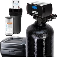
System Components
- Digital Control Valve
- Upper Distribution Basket
- Resin Tank (Pre-filled)
- Riser Tube & Bottom Distribution Basket (Pre-installed)
- Thin Profile Hydraulic Meter
- High Strength Bypass Valve
- 1" Yoke Connection (3/4" Available on request)
- Brine Tank Lid
- Grid Plate
- Brine Tank
- 6' of 3/8" Brine Line
- 10' of 1/2" Drain Line
- Power Adapter
- Brine Well
- Float Valve
- Brine Drain Connection

Required Tool List for System Installation
- Channel Locks
- Screwdriver
- Plumber's Tape
- Utility Knife
-
Two Adjustable Wrenches
-
Use 1" (Or 3/4" Depending on system) copper, brass, or PEX pipe and fittings. Some codes may also allow PVC plastic pipe.
• Silicone Grease (Lubricant) - Please note modification to home plumbing may require the use of additional tools.
Required Components not Included with the System
- 80 lbs Extra Course Grade Salt Pellets are needed to fill the brine tank. The softener system will use any kind of salt formulated for water softener use, but it is advised to use the pellet-shaped salt as it tends to dissolve more evenly. (Potassium can be used for a salt-free alternative)

WARNING! For your safety, the information in this manual must be followed to minimize the risk of electric shock, property damage or personal injury.
II. Installation Safety Guide
IMPORTANT! The following conditions for feed water supply must be met or warranty will be void and the manufacturer assumes no responsibility for damage to system or property.
1. Water Temperature Parameter
The system MUST NOT be installed in an area where it is exposed to direct sunlight and must be protected against freezing and extreme heat.
• Maximum: 100irc F ( 37.8irc C)
• Minimum: 32irc F ( 0irc C)
2. Water Pressure Parameter
The maximum allowable inlet water pressure is 125 psi. If daytime pressure is over 80 psi, night time pressure may exceed the maximum allowed water pressure. Use a pressure reducing valve (PRV) to reduce the pressure if needed.
• Maximum: 125 PSI (8.78 kg/cm2)
• Minimum: 25 PSI (1.75 kg/cm2)
3. Chlorine & Chloramine Tolerance
Softener resin may degrade in the presence of chlorine or chloramines. Feedwater that contains these contaminants will reduce the life of the resin. In these conditions, a whole house carbon filtration system with chlorine, chloramine reducing media is recommended.
• Maximum: 2 ppm
4. Pre-install environment checklist
- Not for use with microbiologically unsafe water. Pre-filtration to remove contaminants and heavy sediment recommended to ensure optimum performance and product life.
- Properly ground to conform with all governing codes and ordinances. Use only lead-free solder and flux for all sweat-solder connections as required by state and federal codes.
- Place softener as close as possible to the pressure tank (well system) / water meter (city water).
- Place softener as close as possible to a floor drain, or other acceptable drain point (laundry tub, sump, standpipe, etc.) to prevent air breaks and back flow.
- Place softener in a place where water damage is least likely to occur if a leak develops.
- The brine tank should be located no more than 10' from the resin tank.
- Connect the softener to the main water supply before the water heater. Do not run hot water through the softener. Maximum temperature of softener water is 100irc F.
- Outside faucets and irrigation systems should be supplied with pre-softened water. If this is not possible, be sure to bypass the softener when watering grass or plants. Chronic soft water exposure can be detrimental to plant life.
4. Pre-install environment checklist (Continued)
- A 120 volt electric outlet must be within 6 feet of the softener. The transformer has an included 8 foot power cable. Be sure the electric outlet and transformer are protected from water and wet weather.
- If installing outside, necessary steps must be taken to ensure the softener, installation plumbing, wiring, etc. are protected from the elements and contamination sources.
- Handle with care when moving the water softening system. Do not drop, drag, or set on areas with sharp protrusions.
- The system works on standard 120v power plug only. Do not use any other transformer except the one that is included with the system.
• Transformer must be plugged into an indoor 120 volt, grounded outlet.
- Use only clean water softening salt with at least 99.5% purity. Extra course grade or crystal salt is recommended. Do not use rock, block or granulated salts. These contain contaminants that could cause problems during maintenance.
• Always keep salt lid in place on the softener unless servicing or refilling the unit.
- Some applications may not have a level surface to place the tank. The floating base allows the tank to be leveled within the base and ensures proper operation.
CORRECTCORRECTINCORRECTINCORRECT

natural_image
Four identical cylindrical containers with black bases, arranged in two groups (no text or symbols)III. Installation Diagram
The following diagram displays how the water softener should be installed with a well or city water setup. If you have city water, your plumbing arrangement will vary but the installation principles are the same. This is an example of how a pre-filter, media tank and water softener flow in line together. If you do not have a media tank/ carbon filter with your purchase, then exclude it from your installation. A loop installation with shut-off valves is advised as seen below.

flowchart
graph TD
    A["Treated Water Out"] --> B["Brine Tank"]
    B --> C["Water Softener"]
    C --> D["Carbon Filter"]
    D --> E["Pre-Filter"]
    E --> F["Pressure Tank"]
    F --> G["Well Head"]
    H["Backwash Line To Drain"] --> I["120 Volt"]
    J["120 Volt"] --> K["Carbon Filter"]
    L["To Outside Water"] --> M["Pressure Tank Well Head"]
INSTALLING THE SYSTEM
IMPORTANT! Locate and test the main water supply valve to the home before installing the system. If the main water supply valve fails to shut off the water completely during the test, we recommend contacting your local plumber to fix the valve before installing the system.

A. Control Head
B. Bypass Valve
C. Water Connection Hoses (Not Included)
D. Upper Basket
E. Resin Tank
F. Brine Line (Blue Clip)
G. Drain Line (Orange Clip)
H. Quick Connection (Float Assembly)
I. Control Head Power
STEP 1. Shut off the Main Water Supply Valve
- Locate the main water supply valve of the house and turn off completely by turning the shut-off handle clockwise.
- Test to see if the water is completely shut off by turning on the closest faucet in the cold water position. If the cold water cannot be shut off, please contact your local plumber to fix the valve before begin installing the system.
STEP 2. Mounting the Control Valve
-
Attach the bypass valve onto the control head and secure it with the metal plates. Make sure the o-rings are lubricated before connecting. (Silicone Grease recommended as lubricant.)
-
Make sure the o-rings are lubricated before installing. Lubricate both O-rings on the bottom of the control valve (inner and outer).
-
Lubricate the riser tube located on the opening of the tank. Make sure riser tube is flush with the top of the tank.
-
Install the upper basket on the bottom of the valve by lining up the tabs, pressing in, then turning the basket counterclockwise to lock it in place.
-
Place the upper basket over the distributor tube and push the valve on the tank. Thread the valve on the tank by turning it clockwise. Be sure not to cross-thread the valve on the tank. The valve should thread easily in the tank. If not, it may be cross-threaded.
DO NOT LUBRICATE as you may over-tighten the valve.
- Tighten the valve hand tight, then snug it further by tapping it with the palm of the hand. DO NOT use tools to tighten the valve or damage could occur.

STEP 3. Connecting the Softener
IMPORTANT! On copper plumbing systems, be sure to install a grounding wire between the inlet and outlet piping to maintain grounding.

WARNING! Any solder joints being soldered near the valve must be done before connecting any piping to the valve. Always leave at least 6" (152 mm) between the control valve and joints being soldered when soldering pipes that are connected to the valve. Failure to do this could cause damage to the valve.
-
The control valve is equipped with 1" male NPT connections. It is recommended that these connections are made using 8-12 wraps of plumber's tape.
-
The inlet and outlet can be identified by the arrows stamped in the bypass valve showing the flow direction. The arrow pointing toward the valve is the inlet and the arrow pointing away from the valve is the outlet.
-
Apply the plumber's tape onto the bypass inlet and outlet fittings.
-
Connect the inlet and outlet of the softener using appropriate fittings.
-
All piping should be secured to prevent stress on the bypass valve and connectors.
-
Connect the drain hose to the valve by removing the orange lock clip and push the 1/2" black tubing into the hole. Secure the line by pushing the locking clip back in.
-
Pull the drain line to see if it is secure. Run the drain hose to the nearest laundry tub or floor drain. This can be run a max of 7 ft overhead or down along the floor. Drain hose should be a minimum of 1/2". If running the drain line more than 20 ft linear, it is recommended to increase the hose size to 3/4" and be sure there are no sags or "drops" in the hose on the way to the drain destination.

natural_image
Close-up of a black industrial pump or motor assembly with dual circular components and connectors (no visible text or symbols)
natural_image
Close-up of a mechanical assembly with blue and red components, no visible text or symbols
natural_image
Close-up of a black motorcycle head with attached red brake calipers and hoses (no visible text or symbols)Note:
A direct connection into a waste drain is not recommended. A physical air gap of at least 1.5" should be used to avoid bacteria and wastewater traveling back through the drain line into the softener.
STEP 4. Connecting the Brine Tank
- Connect the brine line to the control valve by removing the blue locking clip on the brine line connector.

natural_image
Close-up of a mechanical assembly with a blue circular component and orange arrow indicating direction (no visible text or symbols)- Push the brine line into the brine line connector and make sure it goes through the o-ring. Secure by pushing in the locking clip. Pull the brine line to see if it is secure.

natural_image
Close-up of a car brake system with visible tire and wheel assembly (no text or symbols)IMPORTANT! Make sure the brine line is secure to the connection provided on the brine tank. If the brine line is not secure and sealed, it may not be able to perform a proper system regeneration when needed, and can potentially cause overfill in the brine tank and result in leaks.
-
Your brine tank system is 90% pre-assembled. To finish the setup, remove the white lid on top of the brine well.
-
Push the brine line through the opening on the side of the brine tank, and also through the opening on the side of the brine well.
-
Connect the brine line to the quick connection on top of the float assembly, and make sure it is thoroughly connected.
-
Pour in 80 lbs (two bags) of course grade salt and 5 gallons of tap water into the brine tank.

natural_image
Top-down view of a mechanical component with a central pin inserted into a white cup, mounted on a metal tray (no visible text or symbols)IMPORTANT! This optional brine tank overfill connection step is not required. For additional security against leaks and prevention of disrupted service purposes only.
Optional Brine Tank Overfill Connection:
Below the brine hose connection you will notice a 90-degree barbed connection facing downward. This connection is optional since the brine well is equipped with an automatic float valve shutoff.
If you still want to utilize the overfill connection, lubricate the barbed connection with silicone grease or any food-grade oil. You will need to purchase an additional 12 " plumbing hose and place the hose onto the connection for a secure seal. Typically, the other end of the hose will feed off into a floor drain, laundry style sink, or dedicated drain connection.
Brine Tank Components
- Brine Tank with Lid
- Quick Connect Brine Line Connection
- Optional Overflow Line Connection
- Float Valve
- Brine Well
- Flow Regulator
- Grid Plate

Note:
Assembly (color and shape of elements) may vary from previous versions of the product.
STEP 5. Flushing and Testing the Plumbing Lines
WARNING! If the system is leaking at all, turn the unit to the bypass position and shut off main water supply before assessing leak.
IMPORTANT! Flushing the system lines is necessary to ensure that all plumbing work has been done correctly, that there is no debris or air trapped in the piping, and that there are no leaks.
-
Place the unit in the bypass position. Locate the nearest faucet and remove aerator (faucet screen) if there is any. Turn the cold water position on at the nearest faucet and slowly turn on the main water supply. Let the water run for a few minutes or until the system is free of any air or foreign material.
-
Make sure there are no leaks in the plumbing system before proceeding and shut off the nearest faucet when water runs clear.

IMPORTANT! The system is not ready for service until you complete the "System Startup" section of the owner's manual. (Page 13)
STEP 1. Become Familiar with Display Screen
IMPORTANT! Each button has multiple functions and has unique features when pressed during different settings or screens. They can be combined with other buttons to execute the different functions of the valve. Please be familiar with the buttons to operate the control valve.

- Flow Meter Indicator (Appears when running water)
- Time of Day
- Status
- Volume Remaining
- Regeneration Mode ① Time Meter Delay ② Timer ③ Meter Immediate

ENTER Button UP /

Buttons CYCLE Button

WARNING! DO NOT UNPLUG THE UNIT'S POWER SUPPLY DURING REGENERATION!
To Cancel Regeneration
During regeneration, if there is a need to stop the process, press the ⬇ simultaneously to stop regenerating. The display will return to the home screen after a few moments.
The display will show as:

Note:
Make sure the system is powered on before starting. Plug the power transformer into an approved power source. Connect the power cord to the control valve head and before continuing ensure that 5 gallons of water and at least 80 lbs of salt have been added to the brine tank.
STEP 2. System Startup
- When power is supplied to the control, the screen will display the time of day, gallons remaining and the regeneration mode. Press and hold the "Cycle" button for 5 seconds until you see the words "90to bw" and then release the "Cycle" button. The backwash (bw) will be underway.
- Once the valve is in the backwash (b) cycle, you will see the 15-minute (015) countdown next to "b". Open the inlet on the bypass valve slowly and allow water to enter the unit. If you hear any large "knocking" sounds, turn the red inlet valve partially closed (not all the way) as the water is being fed too quickly and should be slowed. This process will begin to purge air from the resin tank and fill the resin tank with water, allowing the air to escape to the drain line. The water to the drain line will eventually start to run clear after 3-4 minutes.
- After the backwash you will see the system move into the brine draw (bd). The brine draw is 60 minutes total and will normally draw out the saltwater within 20-30 minutes leaving the rest of the time for the saltwater to bond with the resin. After the BD the rapid rinse (rr) will start for a duration of 10 minutes. Allow the entire cycle to run so the resin is rinsed clean.
- When the rinse cycle is complete, the control screen will move on to the brine fill (bF). This phase will fill water back into the brine tank. You should gradually start to see the water level rise to half a tank full. Let the entire brine fill finish.
- When the regeneration cycle is complete, open the outlet side of the bypass completely allowing water to flow into your home. From this point, locate the nearest treated water faucet. Remove the aerator screen and run the cold water until the water is completely clear. Once done, shut off the faucet water and place the aerator screen back on the faucet.
STEP 3. Programming the System
IMPORTANT! The settings are pre-programmed from the factory to work with the majority of homes. We recommend programming the system from settings 1 - 4 and leave settings 5 - 8 at system default unless the condition of water requires adjustment.


Enter Setting Menu by pushing both the ENTER button and UP button at the same time. The screen will jump from the service screen with the faucet icon to the first setting screen to set time.


IMPORTANT! The system will default to regenerate at 2 am in the morning based on the time entered in the setting. Setting the correct time of the day will ensure that the system regenerates at the corresponding regeneration time.

flowchart
graph TD
    A["Press the ENTER button to adjust the time setting."] --> B["Set the hour"]
    B --> C["Press UP or DOWN buttons to change hours."]
    B --> D["Press the ENTER button to accept and continue."]
    B --> E["Set the minutes"]
    E --> F["Press UP or DOWN buttons to change minutes."]
    E --> G["Press the ENTER button to accept and continue."]
    H["11:30 SET - 16TM"] --> I["Flashing"]
    J["11:30"] --> K["Flashing"]
    L["11:30"] --> M["Flashing"]
IMPORTANT! The system offers three mode types depending on your needs. It is recommend to set the system at (E ap) Time Meter mode which allows the system to regenerate at 2 am in the morning once the gallons reaches zero.
Press the ENTER button to adjust the regeneration type setting.


Choose Between Time, Meter or Meter Delayed
Note:
It is recommended to set the system to Time Meter.

TIME METER DELAYED
Regenerate at 2 am on the night after the set gallon reaches zero.

TIMER
Allow system to regenerate based on set Lime interval.

METER
Regenerate immediately after the sel gallon reaches zero.
Press Up or Down buttons to change mode.


Press the ENTER button to accept and continue.


IMPORTANT! This setting will only appear if the either (n) Meter or (t n) Time Meter mode from the previous setting was selected. User will not see this setting if (t) Timer mode was selected. The system default is 1000 gallons with the option to change the unit measurement and the capacity of the water treated before the system goes through a regeneration. It is recommended to set the unit of measurement at (qRL) gallons and also calculate the correct amount of gallons the system can treat by going through the worksheet on page 21 of owner's manual or by visiting our website https://aquasureusa.com/calculationtool
Press the ENTER key to adjust the unit capacity setting.


Set Unit Measurement - Gallons, Liters or Cubic Meters (Recommend setting to Gallons for US Customer)

Gallons (Recommended)

Liter: Cubic Meters
Press UP or DOWN buttons Lo change units.


Press the ENTER button to accept and continue.


Press UP or DOWN bullons to set water capacity.


Press the ENTER button to accept, and the number to the left flashes.


IMPORTANT! Depending on the mode selected, the default setting may be set to regenerate at every 72 hours. Even if (n) Meter or (t n) Time Meter mode is selected, the regeneration override will still allow the system to regenerate even if the gallons didn't count down to zero. It is highly recommended to keep the setting at OFF if (n) Meter or (t n) Time Meter mode was selected.
Press the ENTER Key to adjust the time and hour override setting.


(ε) Time Mode
Default: 2:00 a.m. - 072 hours Hours Override range: Every 24 hours (24, 48, 72... 960)
Use UP and DOWN buttons to adjust the Regeneration Time.


Press ENTER to go to Hours Override.


Use UP and DOWN buttons to adjust Hours Override.


Press the ENTER button to accept and continue.


Use UP and DOWN buttons to adjust the Regeneration Time.


Press ENTER to go to Hours Override.


Use UP and DOWN buttons to adjust Hours Override.


Press the ENTER button to accept and continue.


IMPORTANT! You may hit the button to exit to the main menu after setting up the gallons needed for regeneration. Settings 5 - 8 have been preset from the factory and are only meant for special applications that require customized settings. Consult your Aquasure Support Team for further guidance if needed. 800-661-0680
5. Setting the Back Wash Time (Recommend keeping at factory default setting)
(bw) Backwashing time allows the system to flush out any debris or particles that may enter the resin tank. It also helps create space in between the resins to allow more contact surface for the next stage of regeneration. The default setting is 15 minutes.

Set the Time
Default setting is 0.15
Press UP or DOWN buttons to change Back Wash Lime (Minutes). Range: 0 - 999
Press the ENTER button to accept and continue to the next digit.


6. Setting the Brine Time (Recommend keeping at factory default setting)
(b d) Brine Draw pulls the brine water from the brine tank and allows the resin to mix with the brine water, regenerating the system. The more contact time the system is set the more time it allows the resin to bond with the brine water. The default setting is 60 minutes.
Press the ENTER Key to adjust the brine draw time setting.


Set the Time
Default setting is 060
Press UP or DOWN buttons to change Brine time (Minutes). Range: 0 - 999


Press the ENTER Button to accept and continue to next digit.

7. Setting the Rapid Rinse Time (Recommend keeping at factory default setting)
(r-r) Rapid Rinse time allows the system to flush the hardness and residual debris that may be left inside the system out to the drain. The default setting is 10 minutes.

Set the Time
Default setting is 0.10
Press UP or DOWN buttons to change Rapid Rinse time (Minutes). Range: 0 - 999
Press the ENTER button to accept and continue to the next digit.


8. Setting the Water Filling Time (Recommend keeping at factory default setting)
(bF) Brine Fill time allows the system to fill the brine tank back up with the water for the next regeneration. Depending on the water pressure of the source water and the lime set for brine fill, the amount of water inside the brine tank may vary. The default setting is 12 minutes.

Set the Time
Default setting is 0.12
Press Up or Down buttons to change Water Filling Time (Minutes). Range: 0 - 999
Press the ENTER Button to accept and continue to next digit.


GALLONS CALCULATION TOOL
The control valve head uses a meter to count the gallons of water being treated through the system. Once the gallons programmed in the unit have been exhausted, the system will regenerate. The total gallons of treatable water the system can produce is based on the system size, family size, and the hardness level of the feed water. A simple calculation is done to determine the amount of gallons to input during the "Setting 3" programming portion of the installation.
NOTE: This calculation must be completed to program the unit:
Total Gallons = System Capacity in Grains (see chart below) / Hardness in (GPG) Grains Per Gallon (determined by water test) - Number of People X 75 Gallons
| Parameter Aquasure Water | Softener | ||
| Medium Salt Curve Capacity Setting 24,000 - Brine Fill Settings in Minutes 8 10 12 | 40,000 40,001 -56,000 | 56,001 - 80,000 | |
Example:
System Capacity: AS-HS32D System/32,000 Grains (chart above) Feed Water Hardness: 25 GPG (must be tested on-site by the end user or installer) Number of People: 3
(32,000 Grains / 25 GPG) - (3 People X 75 Gallons) 1,280 Gallons - 225 Gallons = 1,055 Total Gallons
1,055 Gallons would be inputted for Total Gallons during "Setting 3" programming.
If the hardness level is given in ppm or mg/L, it can be converted to Grains Per Gallon by dividing the value by 17.1.
ONLINE GALLONS CALCULATION TOOL
Use your phone to scan the QR code below or visit aquasureusa.com/calculationtool for our online gallons calculation tool. If you need further assistance, contact our support team at support@aquasureusa.com.

Input the site values in the equation below to figure out your total gallons value:
(____Grains / ____GPG) - (____ People X 75 Gallons) ____Gallons - ____Gallons = ____ Total Gallons
ADDITIONAL FEATURES & DISPLAYS
1. Display in Service
Timed Regeneration Mode
The display will show the current time, remaining time to the next set regeneration, and the days override.
The display will show the current time and the remaining treated water to the next regeneration.
Time Meter Regeneration Mode
The display will show the current time and the remaining treated water alternatively. When the remaining treated water counts down to zero the display changes to the countdown of time till regeneration starts.


3. Restore factory settings
1) Disconnect power to the control head.
2) Press and hold the button and plug in the power.
3) Release the button.
The system will go through the reset and restore to factory setting.
Note: The system may take a few moments before returning to the normal screen.
![11:30 -RESET [::]](/content/2026/05/958455/images/0f5219c94fa3d34a9ed81dba8f00a796edd1e8d7f645183ced53262af91448a4.jpg)
4. Manual regeneration
Queued Regeneration
When the valve is in service position press the button to activate the queued regeneration.
Queued Regeneration means the system will initiate a regeneration at the time set. If missed, it will initiate on the next day.

The display shows the Queued Regeneration in Meter Delay Mode.
The system will initiate a regeneration - either the treated water remaining counts down to zero or the remaining time counts down to zero, whichever is first.
18
5. Immediate Regeneration
From the home screen, press and hold the button for 5 seconds. An immediate regeneration will be initiated.
Your screen will feature this display as soon as the regeneration begins.

TECHNICAL SPECIFICATIONS
PRODUCT DIMENSIONS
| Aquasure Water Softeners | ||||
| Capacity (In Grains) | Tank Size A B C | |||
| 24,000 8"x44" | 52" 44" 8" | |||
| 32,000 8"x44" | 52" 44" 8" | |||
| 40,000 9"x48" | 56" 48" 9" | |||
| 48,000 10"x54" | 62" 54" 10" | |||
| 64,000 12"x52" | 60" 52" 12" | |||
| 80,000 13"x54" | 62" 54" 13" | |||

Flow Rate @ 50 psi (3.5 bar) Valve Alone:
Continuous 15 psi (1 bar) Drop: 20 gpm (76 lpm)
Peak 25 psi (1.7 bar) Drop: 26 gpm (98 lpm)
Max Backwash 25 psi (1.7bar) Drop: 7 gpm (26 lpm)
CV 1 psi (0.07 bar) Drop: 5.0
Regeneration/Backwash:
Downflow/Upflow: Downflow Cycles: 5
Adjustable Cycles: All
Time Available: Up to 999 minutes per cycle
Meter:
Accuracy Range:
Turbine Paddle 0.25 - 15 gpm
(0.95 - 57 lpm) ± 5%
Capacity Range: 1 - 9,999,999 gal
Valve Specifications:
Inlet/Outlet: 1" or 3/4", NPT
Mounting Base: 2-1/2" 8 NPSM
Distributor Pilot: 1.05" OD
Drain Line: 1/2" Quick Connect Elbow
Brine Line: 3/8" Quick Connect
Height: 7" (178 mm)
Weight (Valve Gross): 4.84 lb (2.1 kg)
Additional Information:
Electrical Rating: Input: 120V AC 60Hz, Output: 24 V DC
Max. VA 3 VA
Water Pressure: Hydrostatic: 300 psi (21 bar) Working: 20 - 125 psi (1.4 bar - 8.6 bar)
Temperature: 34 - 110 °F (1 - 43 °C)
SYSTEM TROUBLESHOOTING
Use your phone to scan the QR code below or visit https://aquasureusa.com/support for most up to date system troubleshoot. You can also contact our support team at support@aquasureusa.com.

Valve Body Assembly and Parts List
| Item No. | Quantity Part No. | Description | |
| 1 3 A-12112 Screw | |||
| 2 1 A-13546 End Plug Retainer | |||
| 3 1 A-13363 Washer | |||
| 4 1 A-13296 Screw | |||
| 5, 6, 7, 8 1 A-60102 | 20 Piston Softener & Filter | ||
| 9, 10 1 A-60125 Seals (5) & Spacers (4) Assy. | |||
| 11 1 A-61400-34 Valve Body Assembly, 3/4" Dist. | |||
| 12 4 A-13305 O-ring, Adapter Coupling | |||
| 13 2 A-19228 Adapter Coupling | |||
| 14, 15 2 A-13255-FT Kit Adaptor Clip | |||
| 16 1 A-187706 Yoke, Plastic, 1" | |||
| 1 A-187706-02 Yoke, Plastic, 3/4" | |||
| 17 1 A-13304 O-ring, Distributor Riser Tube | |||
| 18 1 A-12281 O-ring, Top of Tank | |||
| 19 1 A-56247 Drain, Quick Connector, Elbow, 1/2" Tubing | |||
| 20 1 A-01019 O-ring, DLFC | |||
| 21* 1 A-120XX | DLFC Button | ||
| 22 1 A-50011 Locking Clip, Drain QC | |||
| 23 1 A-13245 BLFC Button Retainer | |||
| 24** | 1 A-120XX | BLFC Button | |
| 25, 26, 27 | 1 A-13244 Brine Line | Quick Connector 3/8" Tubing | |
| 28 2 A-13315 Screw | |||
| 29 1 A-13166 Injector Cover | |||
| 30 1 A-13303 O-ring, Injector Cover | |||
| 31 1 A-01002 O-ring, Injector (Included w/ Injector) | |||
| 32*** | 1 A-10225-X-N | Injector | |
| 33 1 A-01017 O-ring, Injector (Included w/ Injector) | |||
| 34 1 A-56226 Screen, Injector | |||
| 35 1 A-13163 Injector Body | |||
| 36 2 A-13301 O-ring | |||
| 37 1 A-13497 Air Disperser | |||
| 38 1 A-12638 O-ring | |||
| 39 - 45 1 A-60032 Brine Valve Assy | |||
| 46 1 A-13918 BLFC Plug | |||
| 47 1 A10913BLK-02 | Injector Black Capped | ||
| 48 1 A-13857 Brine Valve Plug | |||
* Extra Option

| Item No. | Quantity Part No. | Description | |
| 1 1 A-19791-01 Meter Cable, Turbine AQT-56SE | |||
| 2 4 A-13305 O-ring | |||
| 3 | 2 | A-13255-SE Adapter Clip | |
| 4 | 2 | ||

LIMITED PRODUCT WARRANTY
Aquasure warrants to the original retail purchaser that this Harmony Water Softener is free from defects in material and workmanship, and agrees to replace, at Aquasure's discretion, any defective product free of charge within the warranty time periods from the date of purchase.
This warranty extends to the original retail purchaser only and commences on the date of the original retail purchase of the Aquasure Harmony Series water softener system. The only exception shall be when proof of purchase or installation is provided and then the warranty period shall be from the date thereof.
- One year valve, electronics, and resin warranty if the product is not registered within 60 days of purchase.
- Five year valve, electronics, and resin warranty if the product is registered with Aquasure.
For information on how to register your product, view page 2
Valve, Electronics and Resin Guarantee
Aquasure will replace any part of the valve or electronics found in reasonable judgment to be defective in material or workmanship. Resin and internal control valve parts will not be covered for systems used to remove iron, manganese or chlorine that is above the suggested level for system operation.
Ten Year Warranty on Resin Tank and Brine Tank
Aquasure will provide a replacement resin tank or brine tank to any original equipment purchaser in possession of the Aquasure water softener that fails for (10) ten years after the date of purchase, provided that it is at all times operated in accordance with specifications and not subject to freezing.
General Provisions
Aquasure assumes no responsibility for incidental damage, consequential damage, or other damages including, but not limited to, installation expense, telephone charges, rental of a like product during the time warranty service, travel loss or damage to personal property, loss of revenue, loss of use of the product, loss of time, or inconvenience.
No warranty is made with respect to defects or damage due to neglect, misuse, alterations, accident, misapplication, physical damage, or damage caused by fire, freezing, or other environmental damage. Improper maintenance, or installation outside the recommended specs at any time will be considered neglect and void warranty.
These warranties are in lieu of all other warranties expressed or implied, and we do not authorize any person to assume for us any other obligation on the sale of this water conditioner. No responsibility is assumed for delays or failure to meet these warranties caused by strike, government regulations or other circumstances beyond the control of Aquasure.
Obtaining Warranty Coverage or General Inquiries
If coverage is available, you may obtain coverage under this Limited Product Warranty by providing Aquasure with proof of original purchase, and that you are the original retail purchaser. For warranty service under this Limited Product Warranty, you must notify Aquasure by phone at 1-800-661-0680, by email at support@aquasureusa.com.
SOME STATES DO NOT ALLOW THE EXCLUSION OR LIMITATIONS OF INCIDENTAL OR CONSEQUENTIAL DAMAGES SO THE ABOVE LIMITATION MAY NOT APPLY TO YOU. THIS WARRANTY GIVES YOU SPECIFIC LEGAL RIGHTS, AND YOU MAY ALSO HAVE OTHER RIGHTS WHICH VARY FROM STATE TO STATE.
NOTES
NOTES
AQUASURE

- WHOLE HOUSE WATER SOFTENER
- OWNER'S MANUAL
- IMPORTANT!
- TABLE OF CONTENTS
- WELCOME & CONGRATULATIONS 1
- EXTENDED WARRANTY REGISTRATION 2
- INSPECTION & PREPARATION 3
- INSTALLING THE SYSTEM 7
- GALLONS CALCULATION TOOL 21
- ADDITIONAL FEATURES & DISPLAYS 23
- TECHNICAL SPECIFICATIONS 25
- LIMITED PRODUCT WARRANTY 29
- WELCOME & CONGRATULATIONS
- For MAXIMUM effectiveness please thoroughly read this manual.
- DON'T MISS OUT ON FOUR FREE YEARS WITH AQUASURE EXTENDED WARRANTY
- Registration with your mobile device is easy.
- INSPECTION & PREPARATION
- System Review and Installation Tools
- System Components
- Required Tool List for System Installation
- Required Components not Included with the System
- Installation Safety Guide
- Water Temperature Parameter
- Water Pressure Parameter
- Chlorine & Chloramine Tolerance
- Pre-install environment checklist
- Pre-install environment checklist (Continued)
- Installation Diagram
- INSTALLING THE SYSTEM
- STEP 1. Shut off the Main Water Supply Valve
- STEP 2. Mounting the Control Valve
- STEP 3. Connecting the Softener
- Note:
- STEP 4. Connecting the Brine Tank
- Optional Brine Tank Overfill Connection:
- Brine Tank Components
- STEP 5. Flushing and Testing the Plumbing Lines
- STEP 1. Become Familiar with Display Screen
- WARNING! DO NOT UNPLUG THE UNIT'S POWER SUPPLY DURING REGENERATION!
- To Cancel Regeneration
- STEP 2. System Startup
- STEP 3. Programming the System
- TIME METER DELAYED
- TIMER
- METER
- (ε) Time Mode
- Setting the Back Wash Time (Recommend keeping at factory default setting)
- Set the Time
- Setting the Brine Time (Recommend keeping at factory default setting)
- Setting the Rapid Rinse Time (Recommend keeping at factory default setting)
- Setting the Water Filling Time (Recommend keeping at factory default setting)
- GALLONS CALCULATION TOOL
- Example:
- ONLINE GALLONS CALCULATION TOOL
- ADDITIONAL FEATURES & DISPLAYS
- Display in Service
- Timed Regeneration Mode
- Time Meter Regeneration Mode
- Restore factory settings
- Manual regeneration
- Immediate Regeneration
- TECHNICAL SPECIFICATIONS
- Regeneration/Backwash:
- Meter:
- Valve Specifications:
- Additional Information:
- SYSTEM TROUBLESHOOTING
- LIMITED PRODUCT WARRANTY
- Valve, Electronics and Resin Guarantee
- Ten Year Warranty on Resin Tank and Brine Tank
- General Provisions
- NOTES
- AQUASURE
Brand : Aquasure
Model : Harmony AS-HS64FMP
Category : Water Softener