
Harmony AS-HS48D - Water Softener Aquasure - Free user manual and instructions
Find the device manual for free Harmony AS-HS48D Aquasure in PDF.

| Product Type | Water Softener |
| Model | Harmony AS-HS48D |
| Brand | Aquasure |
| Capacity | 48,000 grains |
| Dimensions (L x W x H) | 10 x 14 x 48 inches |
| Dry Weight | 40 lbs |
| Power Supply | 110/120V, 60 Hz |
| Operating Temperature | 34°F - 100°F (1°C - 38°C) |
| Water Pressure Range | 20 - 100 psi |
| Max Flow Rate | 10 - 12 GPM |
| Control Valve | Digital metered |
| Regeneration | Automatic, time or demand-initiated |
| Includes | Bypass valve, drain line fittings, manual |
| Maintenance | Annual brine tank cleaning, periodic resin check |
| Safety | UL listed, low voltage transformer |
| Spare Parts Available | Control valve, resin beads, seals, brine tank |
| Warranty | Lifetime on resin tank, 1 year on parts |
| Certifications | NSF/ANSI 44 (typical) |
Frequently Asked Questions - Harmony AS-HS48D Aquasure
User questions about Harmony AS-HS48D Aquasure
0 question about this device. Answer the ones you know or ask your own.
Ask a new question about this device
Download the instructions for your Water Softener in PDF format for free! Find your manual Harmony AS-HS48D - Aquasure and take your electronic device back in hand. On this page are published all the documents necessary for the use of your device. Harmony AS-HS48D by Aquasure.
USER MANUAL Harmony AS-HS48D Aquasure
WHOLE HOUSE WATER SOFTENER OWNER'S MANUAL
FOR MODEL NO.
AS-HS32D
AS-HS48D
AS-HS64D

TABLE OF CONTENT
2 INSPECTION & PREPARATION
2 Understanding How the Water Softener Works
2 I. Be Familiar with the System Before Installation
3 II. System Operation Parameter and Installation checklist
4 III. Installation Safety Guide
6 INSTALLING THE SYSTEM
6 STEP 1. Shutting off the main water supply valve
6 STEP 2. Softener Preparation
8 STEP 3. Connecting the System
10 STEP 4. System Startup
11 STEP 5. Programming the System
20 Total Gallon Calculation
22 FEATURE & DISPLAY
25 PRODUCT DIMENSION
26 SYSTEM TROUBLESHOOT
28 LIMITED PRODUCT WARRANTY
WELCOME
Thank you for choosing Aquasure. Before you starting installing your Aquasure Harmony Series Whole House Water Softener. Please take a few minute to become familiar with the basics.
INSPECTION & PREPARATION
Understanding How The Water Softener Works
The principle behind water softening is simple chemistry. A water softener contains resin beads which hold electrically charged ions. When hard water passes through the softener, calcium and magnesium ions are attracted to the charged resin beads. The result is removal of calcium and magnesium ions which produces soft water.
I. Be Familiar with the System Before Installation

IMPORTANT! Please read the entire manual and become familiar with instructions and parts needed before proceeding with the installation.
Inspect the System
Please take the system and all the components out of the box. Inspect the system and all the connection fittings carefully, make sure nothing is damaged during shipping. If any part is cracked or broken, please do not proceed with the installation and contact Aquasure or your distributor for an exchange or diagnosis.
System Components Breakdown (See Dia. A)
• Aquatrol Valve Electronic Meter
• 4' of 3/8" Brine Line
- Brine Tank
- Bypass Valve
- Drain Line Fitting
• 15' of 1/2" Drain Line
- Top Distributor
- Resin Media
- Resin Tank
• Riser Tube & Bottom Distributor
- Control Valve
• Upper Distributor Basket
• Power Transformer
- Brine Connector Pack
- Small Parts Kit
Required Tool List for System Installation
- Channel Locks
- Screwdriver
- Teflon Tape
- Razor Knife
- Two Adjustable Wrenches
- Plastic inlet and outlet fittings are included with the softener. To maintain full valve flow, 1" pipe to and from the softener fittings are recommended.
- Use copper, bass, or PEX pipe and fittings. Some codes may also allow PVC plastic pipe.
• Additional tools may be required if modification to home plumbing is required.
Required Components not Included with the System
- Extra Course Grade or Crystal water softener salt is needed to fill the brine tank
II. System Operation Parameter and Installation checklist

IMPORTANT! The following condition for feed water supply must be met or warranty will be void and manufacturer assumes no responsibility for damage to system or property.
1. Water Temperature Parameter
System must not be installed at an area where it is exposed to direct sunlight and must be protected against freezing and extreme heat.
• Maximum: 100°F (37.8°C)
• Minimum: 32^ F ( 0^ C)
2. Water Pressure Parameter
The maximum allowable inlet water pressure is 125 psi. If daytime pressure is over 80 psi, night time pressure may exceed the maximum allowed water pressure. Use a pressure reducing valve (PRV) to reduce the pressure if needed.
• Maximum: 125 PSI (8.78 kg/cm2)
• Minimum: 25 PSI (1.75 kg/cm2)
3. Chlorine & Chloramine Tolerance
Softener resin may degrade in the presence of chlorine or chloramines. If the feed water contains chlorine or chloramines, reduced life of the resin could occur. In these conditions, a whole house carbon filtration system with chlorine, chloramine reducing media is recommended.
• Maximum: 2 ppm
4. Pre-install environment checklist
- Do not use with water that is microbiologically unsafe or of unknown quality without adequate disinfection before or after the system.
- Properly ground to conform with all governing code and ordinances. Use only lead-free solder and flux for all sweat-solder connections as required by state and federal codes.
- Place the softener as close as possible to the pressure tank (well system) or water meter (city water).
- Place the softener as close as possible to a floor drain, or other acceptable drain point (laundry tub, sump, standpipe, etc.).
- Connect the softener to the main water supply pipe before the water heater. Do not run hot water through the softener. Temperature of water passing through the softener must be less than 100^ F.
- Outside faucets and irrigation system should be supplied with pre-softened water. If this is not possible, be sure to bypass the softener when watering grass or plants. Chronic soft water exposure can be detrimental to plant life.
- Place softener in a place where water damage is least likely to occur if a leak develops.
- A 120 volt electric outlet is needed within 6 feet of the softener. The transformer has an attached 8 foot power cable. Be sure the electric outlet and transformer are protect from wet weather or water.
- If installing in an outside location, necessary steps must be taken to assure the softener, installation plumbing, wiring, etc. are protected from the elements and contamination sources.
- The resin tank should be located close to a drain to prevent air breaks and back flow.
III. Installation Safety Guide
- Handle with care when moving the water softening system. Do not turn upside down, drop, drag, or set on areas with sharp protrusions.
- The system works on standard 110v power plug only. Do not use any other transformer except the ones that is included with the system
- Transformer must be plugged into an indoor 120 volt, grounded outlet only.
- Use clean water softening salt only with at least 99.5% pure. Extra course grade or crystal salt are recommended. Do not use rock, block, granulated or ice cream making salts. They contain contaminants that could cause problems during maintenance
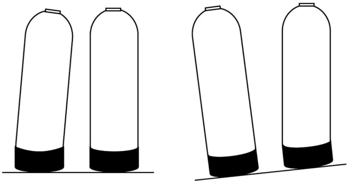
• Always keep salt lid in place on the softener unless servicing or refilling the unit. - All of our resin tanks have level adjusting tank bases. These tanks are designed to work with a "floating" base. This allows the tank to be leveled on any surface. Some applications may not have level surface to place the tank. The floating base allows the tank to be leveled within the base and ensure proper operation. Sometimes the based can shift during shipping. It can be adjusted back by lifting the tank up no higher than 5" - 10", and letting it drop to help level the base.
CORRECTCORRECTINCORRECTINCORRECT
natural_image
Four identical cylindrical containers with black bases, arranged horizontally (no text or symbols)INSTALLING THE SYSTEM

IMPORTANT! Locate and test the main water supply valve to the home before installing the system. If the main water supply valve fails to shut off the water completely during the test, we recommend contacting your local plumber to fix the valve before begin installing the system.

WARNING! If the system is installed on a metal (Conductive) plumbing system, i.e.. copper or galvanized metal, the plastic components of the system will interrupt the continuity of the plumbing system. As a result, any arrant electricity from improperly grounded appliances downstream or potential galvanic activity in the plumbing system can no longer ground through contiguous metal plumbing. Some homes may have been built in accordance with building codes, which actually encouraged the grounding of electrical appliances through plumbing. A grounded "jumper wire" bridging the equipment and reestablishing the contiguous conductive nature of the plumbing system must be installed prior to your system use.
STEP 1. Shutting off the Main Water Supply Valve

WARNING! If the hot water tank is electric, turn off the power to the hot water tank first to avoid damage to the element in the tank. If the source water is coming from a private well. Power off the well water pump and then shut off the main water supply valve.
- Locate the main water supply valve of the house and turn off completely by turning the shut-off handle clockwise.
- Test to see if the water is completely shut off by turning on the closest faucet in the cold water position. If the cold water cannot be shut off, please contact your local plumber to fix the valve before begin installing the system.
STEP 2. Softener Preparation
-
Remove the resin tank from carton
-
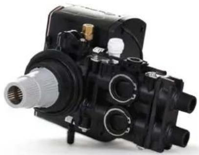
Lubricate both O-rings on the bottom of the control valve (center and outer).

natural_image
Close-up of a mechanical device with visible internal components and green arrows indicating features (no text or symbols)- Install the upper basket on the bottom of the valve by lining up the tabs, pressing in, then turning the basket clock-wise to lock it in place.
natural_image
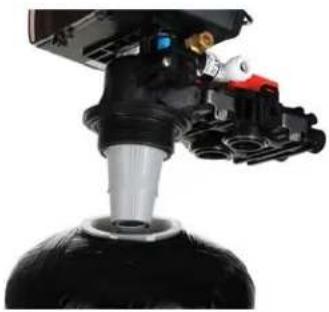
Close-up of a black mechanical pump assembly with internal components (no visible text or symbols)- Place the upper basket over the distributor tube and push the valve on the tank. Thread the valve on the tank by turning it clockwise. Be sure not to cross-thread the valve on the tank. The valve should thread easily in the tank. If not, it may be cross-threaded.
natural_image
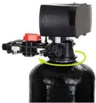
Close-up of a mechanical device with black and red components, no visible text or symbols- Tighten the valve hand tight, then snug it further by tapping it with the palm of the hand. DO NOT use tools to tighten the valve or damage could occur.
natural_image
Close-up of a black industrial water heater with mechanical components and a green circular motion indicator (no visible text or symbols)STEP 3. Connecting the System

IMPORTANT! On copper plumbing systems be sure to install a grounding wire between the inlet and outlet piping to maintain grounding.

WARNING! Any solder joints being soldered near the valve must be done before connecting any piping to the valve. Always leave at least 6" (152 mm) between the control valve and joints being soldered when soldering pipes that are connected to the valve. Failure to do this could cause damage to the valve.
- The Aquatrol valve is equipped with 3/4" male NPT connections. It is recommended that these connections are made using Teflon tape.
- The inlet and outlet can be identified on the bypass valve. There are arrows stamped in the bypass valve showing the flow direction. The arrow pointing toward the valve is the inlet and the arrow pointing away from the valve is the outlet.
- Apply the Teflon tape onto the bypass inlet and outlet fittings.
- Connect the inlet and outlet of the softener using appropriate fittings.
- All piping should be secured to prevent stress on the bypass valve and connectors.
- Connect the drain hose to the valve by pressing it into the Quick Connect port. Run the drain hose to the nearest laundry tub or floor drain. This can be ran up overhead or down along the floor. Drain hose should be a minimum of 1/2". If running the drain line more than 20 ft linear, it is recommended to increase the hose size to 3/4" and be sure there is no sags or a "drop" in the hose all the way to the drain destination.
Note: A direct connection into a waste drain is not recommended. A physical air gap of at least 1.5" Should be used to avoid bacteria and wastewater traveling back through the drain line into the softener.
- Connect the brine line to the control valve by removing the nut on the control valve and sliding it on the brine line. Then install the plastic sleeve on the brine line. Push the brass tube stiffener in the brine line. Install the cone shaped screen in the brass tube stiffener.
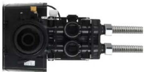
natural_image
Close-up of a mechanical assembly with cylindrical components and threaded connectors (no visible text or symbols)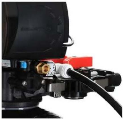
natural_image
Close-up of a black industrial pump with red and black components, no visible text or symbols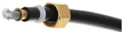
natural_image
Close-up of a black cable with gold connectors and metallic connector (no text or symbols visible)- Push the brine line in the brass fitting on the control valve until it stops. Then push the nut down on the fitting and tighten it hand tight. Use channel locks to tighten the nut an additional 1/2 to 1 full turn.
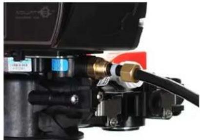
natural_image
Close-up of a mechanical component with hoses and connectors (no visible text or symbols)- Remove the nut from the brine safety valve outside the white brine well. Slide the nut onto the brine line.

natural_image
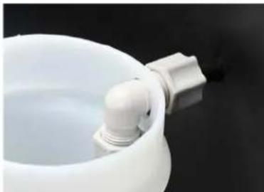
Close-up of a white plastic container with a black plastic clip attached, against a dark background (no text or symbols visible)- Connect the brine line to the brine tank by pushing the brine line through the hole in the side of the tank.

natural_image
Close-up of a black cylindrical object with a thin black cable extending from its side (no text or symbols visible)- Push the brine line into the elbow of the brine safety valve in the brine well until it stops. Tighten the nut hand tight then turn it another 1/2 to 1 full turn with channel locks.
natural_image
Close-up of a white ceramic pot with a small pipe fitting inserted, against a dark background (no text or symbols visible)- Pour in at least two bags of salt and 5 gallons of clean water into the brine tank.
- Place the unit in the bypass position. Slowly turn on the main water supply at the nearest cold treated water tap nearby and remove the faucet screen. Open the faucet and let water run a few minutes or until the system is free of any air or foreign material resulting from the plumbing work.
- Make sure there are no leaks in the plumbing system before proceeding. Close the water tap when water runs clear.
- Open the brine tank lid and add 5 gallons of water to the brine tank. Add a minimum of 80lbs of salt to the brine tank.
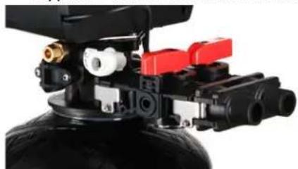
Bypass Position Service Position
natural_image
Close-up of a mechanical device with black housing, red control switches, and yellow fittings (no visible text or symbols)
natural_image
Close-up of a mechanical assembly with red and black components mounted on a black tire (no visible text or symbols)NOTE:
The system is not ready for service until you complete the system startup section of this owner's manual
STEP 4. System Startup

Setting Button
- Enter into setting menu
- Confirm the current setting, and enter into the next step
- When used simultaneously with up button, it will enter into master programming


Up / Down Buttons
- Adjust current settings
- Go one step forward or backward

Cycle Button
- Save the setting and return to service
- Enter into queued regeneration mode
- A long press for 5 - 6 seconds will initiate a immediate regenerate
-
Terminate the current regeneration step and goes to the next step
-
Plug the power transformer into an approved power source. Connect the power cord to the valve.
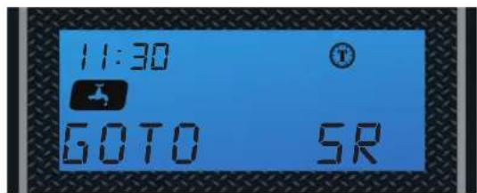
- When power is supplied to the control, the screen will display the time of day, gallons remaining and the mode. Press and hold the "Cycle" button. The valve will display "GOTO BW" and will continue to move until it reaches the backwash system.
-
Once the valve is in the backwash (BW) cycle the display will show a time value (10), open the inlet on the bypass valve slowly and allow water to enter the unit. Air from the tank will begin to push out of the control valve drain. Allow all air to escape from the unit before turning the bypass fully open. If there is a large "knocking" sound, the water is being fed too quickly and should be slowed. Once there is a steady stream of water coming from the system drain with no air coming out, allow water to run to drain for 3-4 minutes or until all media/resin fines are washed out of the softener which is indicated by clear water in the drain hose.
-
When the backwash cycle is complete, the valve will advance to the brine draw (BD) position. Once the valve reaches the BD cycle, push and release the "Cycle" button. The display will show "GOTO RR" (Rapid Rinse). Once the valve reaches the rinse cycle, allow the water to run for the entire rinse cycle
- When the rinse cycle is complete, the valve will advance to the "BF" position. Once in the brine fill position, check that the control valve is pushing water into the brine tank (remove brine well cap to confirm that the water level is rising in the brine tank). Allow the valve to refill for the full amount of time as displayed on the screen to insure a proper brine solution for the next regeneration.
- When the refill cycle is complete, the valve will automatically advance to the SERVICE position. Open the outlet valve on the bypass, then open the nearest treated water spigot or faucet (remove faucet screen to prevent clogging) and allow the water to run until clear, close the tap and replace the faucet screen.
STEP 5. Programming Unit
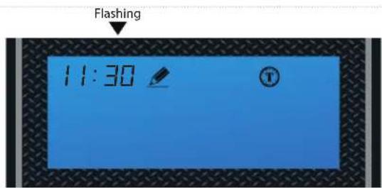
1. Setting Time of Day
Default setting 12:00 (24 hours) Press Settings Button and Up Button simultaneously to enter into Programming Mode
Press Simultaneously


Set the hour
Press Up or Down buttons to change hours.
Press the Settings Button to accept and continue.


Flashing


Set the minutes
Press Up or Down buttons to change minutes.
Press the Settings Button to accept and continue.


2. Setting the Regeneration Mode

Default selling is "Timer"
NOTE:
See page 22 for feature and display in regards to each of the three regeneration mode. Choose the mode that best fit your need.
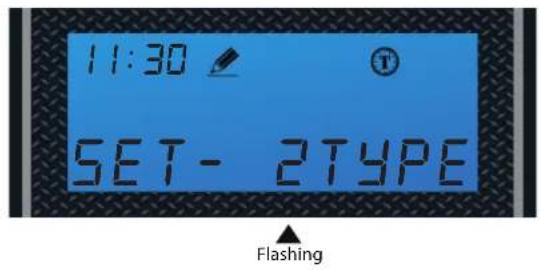

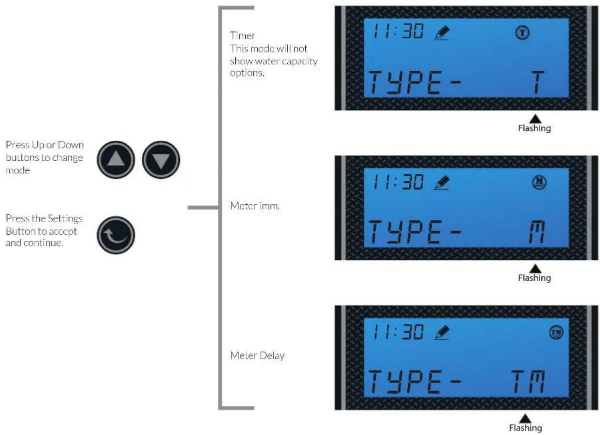
Choose Between Time, Meter Immediate or Meter Delayed
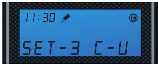
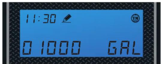
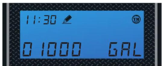
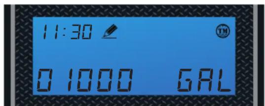
3. Setting the Unit Capacity (Not shown if Timer Mode was selected in 2nd Step)

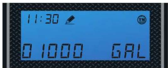
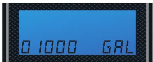
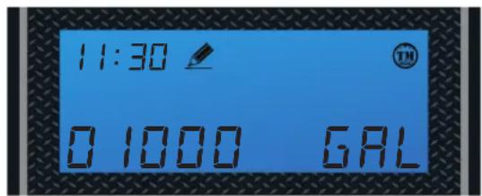
Default setting is 1000 gal
Flashing

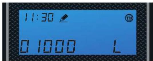
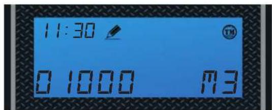
Set Unit Measurement - Gallons, Liters or Cubic Meters
Press Up or Down buttons to Change Unit between:
Press the Settings Button to accept and continue.

Gallons
Liters
Cubic Meters
Flashing
Flashing
Flashing
Press Up or Down buttons to set water capacity.


Press the Settings Button to accept, cursor moves left and the number flashes.

NOTE:
Enter the number of gallons that was determined in the Total Gallons Calculation worksheet in page 20. This worksheet must be completed to determine the proper gallons.
Flashing
Flashing
Flashing
Flashing
Flashing
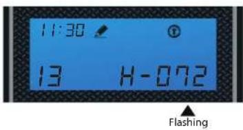
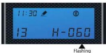
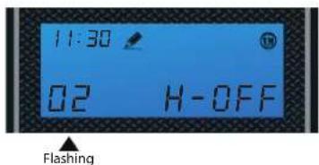
4. Regeneration Time and Hours Override
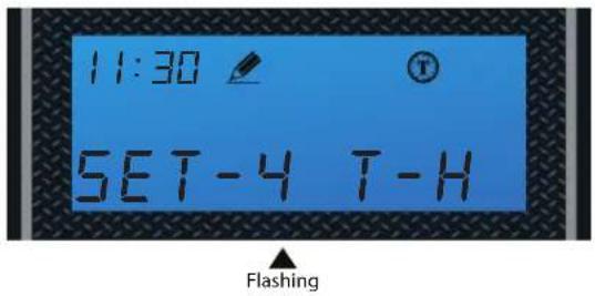
Timer Mode
Default: 2:00 a.m. - 072 hours
Hours Override range:
3, 4, 6, 8, 12 hours, then every 24 hours (24, 48, 76... 960)
Every 24 hours (24, 48, 76... 960)

Use UP and DOWN buttons to adjust the Regeneration Time


Press SET to go to Hours Override

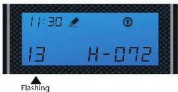
Use UP and DOWN buttons to adjust Hours Override


Use UP and DOWN buttons to adjust the Regeneration Time


Press SET to go to Hours Override

Use UP and DOWN buttons to adjust Hours Override


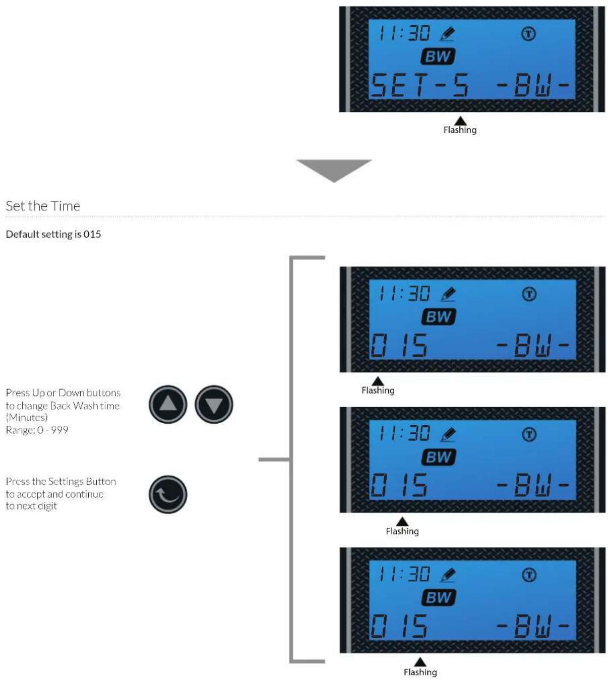
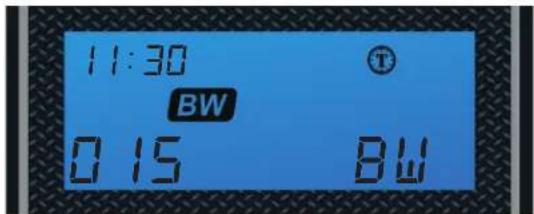
5. Setting the Back Wash Time
flowchart
graph TD
    A["Set the Time"] --> B["Default setting is 015"]
    B --> C["Press Up or Down buttons to change Back Wash time (Minutes) Range: 0 - 999"]
    B --> D["Press the Settings Button to accept and continue to next digit"]
    C --> E["11:30 BW SET-5 -BW-"]
    D --> F["11:30 BW 0.15 -BW-"]
    E --> G["Flashing"]
    F --> H["Flashing"]
    G --> I["11:30 BW 0.15 -BW-"]
    H --> J["11:30 BW 0.15 -BW-"]
    I --> K["Flashing"]
    J --> L["Flashing"]
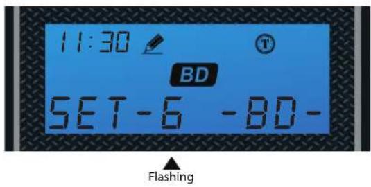
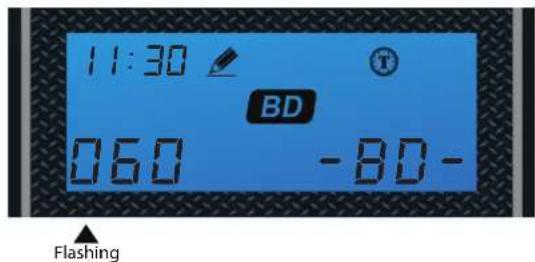
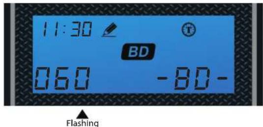
6. Setting the Brine Time

Set the Time
Default setting is 060
Press Up or Down buttons Lo change Brine time (Minutes) Range: 0 - 999
Press the Settings Button to accept and continue to next digit


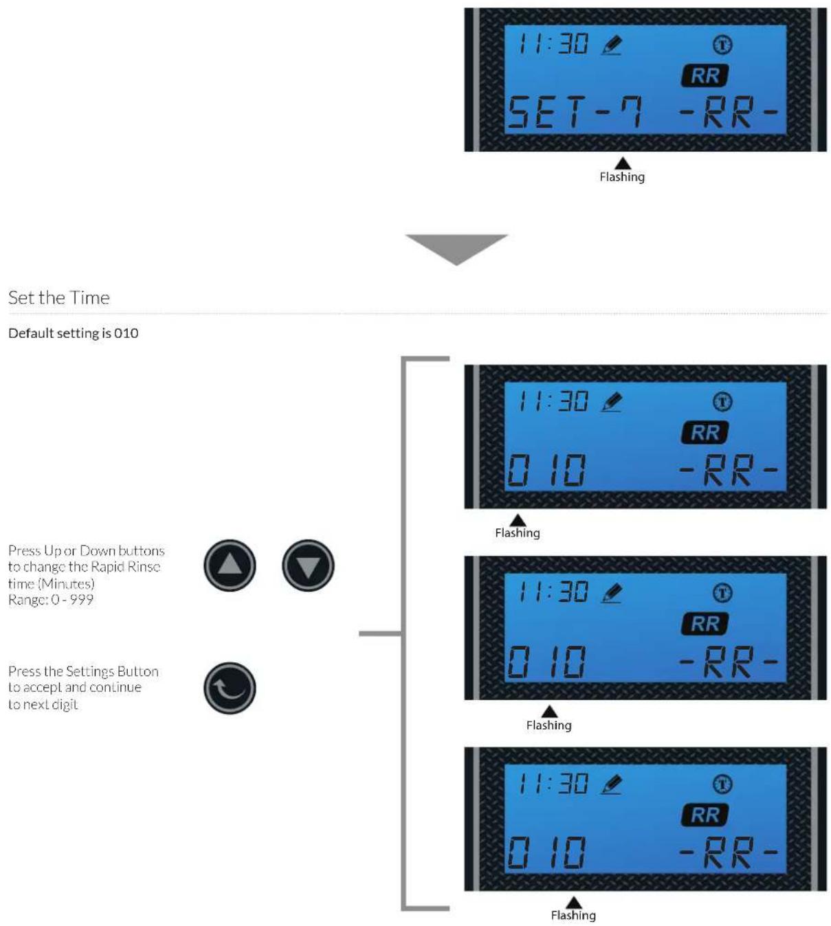
7. Setting the Rapid Rinse Time
flowchart
graph TD
    A["Set the Time"] --> B["Default setting is 010"]
    B --> C["Press Up or Down buttons to change the Rapid Rinse time (Minutes) Range: 0 - 999"]
    B --> D["Press the Settings Button to accept and continue to next digit"]
    C --> E["11:30 SET-7 RR-"]
    D --> F["11:30 0 10 RR-"]
    E --> G["Flashing"]
    F --> H["Flashing"]
    G --> I["11:30 0 10 RR-"]
    H --> J["11:30 0 10 RR-"]
    I --> K["Flashing"]
    J --> L["Flashing"]
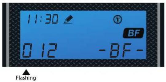
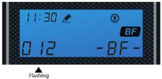
8. Setting the Water Filling Time
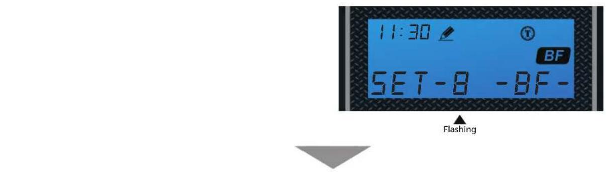
Set the Time
Default setting is 012
Press Up or Down buttons Lo change the Water Filling Time (Minutes) Range: 0 - 999
Press the Settings Button to accept and continue to next digit


NOTE: Use the table below to determine the proper BF setting for your unit.
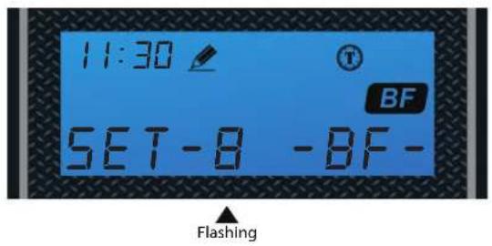

| Parameter | Aquasure Water Softener | ||
| AS-HS32D AS-HS48D AS-HS64D | |||
| Medium Salt Curve Capacity Setting 32,000 48,000 64,000 | |||
| Brine Fill Settings in Minutes 6810 | |||
TOTAL GALLONS CALCULATION
The Aquatrol valve uses a meter to count the gallons of water being treated through the system. Once the gallons programmed in the unit has been exhausted, the system will regenerate. The total gallons of treatable water the system can produce is based on the system size, family size, and the hardness level of the feed water. A simple calculation is done to determine the amount of gallons to input during the programming portion of the installation.
NOTE: This calculation must be completed to program the unit:
Total Gallons = System Capacity in Grains (see chart below) / Hardness in (GPG) Grains Per Gallon (determined by water test) - Number of People X 75 Gallons
| Parameter | Aquasure Water Softener | ||
| AS-HS32D AS-HS48D AS-HS64D | |||
| Medium Salt Curve Capacity Setting 32,000 48,000 64,000 | |||
| Brine Fill Settings in Minutes 6 8 10 | |||
Example:
System Capacity: AS-HS32D System/32,000 Grains (chart above)
Feed Water Hardness: 25 GPG (must be tested on-site by the end user or installer)
Number of People: 3
(32,000 Grains / 25 GPG) - (3 People X 75 Gallons) = Total Gallons
1,280 Gallons - 225 Gallons = 1,055 Total Gallons
1,055 Gallons would be inputted for Total Gallons during programming.
If the hardness level is given in ppm or mg/L, it can be converted to Grains Per Gallon by dividing the value by 17.1.
Input the site values in the equation below to figure out your total gallons value:
(____Grains / ____GPG) - (____ People X 75 Gallons)
____ Gallons - ____ Gallons = ____ Total Gallons
CONGRATULATION!
Your system is ready to use. Please document the system installation time and maintain the system at its recommended interval.
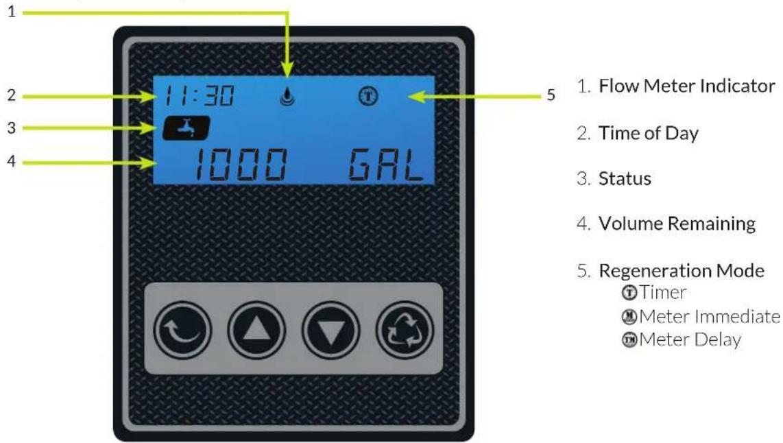
FEATURE & DISPLAYS
1. Display in Service
Timed Regeneration Mode
The display will show the current time, remaining time to the next set regeneration, and the days override.

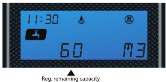
Meter Immediate Regeneration Mode
The display will show the current time and the remaining treated water to the next regeneration.
Meter Delay Regeneration Mode
The display will show the current time and the remaining treated water alternatively. When the remaining treated water counts down to zero the display changes to the regeneration time set by the user.

2. Backlight Screen
The backlight on the screen will go off automatically after one minute if no buttons are pressed. To light it up again press any button on the touch pad.
3. Memory during power failure
All program settings are stored in permanent memory. Current valve position, cycle step elapsed, time of day are stored during the power failure. Reset the current time is necessity when power up.
If the valve stopped at a regeneration stage when power failure, the valve will return to prior position when power up. It takes 4 to 5 minutes to reset to the position.
The display shows as:
The system will show the status when power failure after find the position.
![11:30 RESET [——]](/content/2026/05/1045421/images/d4cfada45100df73c29f396475ad5d54c0e153c9556be85935a9894e0d009316.jpg)
4. Restore factory settings
1) Pull out the power
2) Press the button and plug in the power simultaneously
3) Release the button
The system is now restored
![11:30 RESET [——]](/content/2026/05/1045421/images/94ce12f0a6889f731e78956bd04def5b9370fe27b0da6a63a60b70ac9355f801.jpg)
5. Manual regeneration
Queued Regeneration
When the valve is in service position press the button to activate the queued regeneration.
Queued Regeneration means the system will initiate a regeneration at the time set. If missed, it will initiate on the next day.
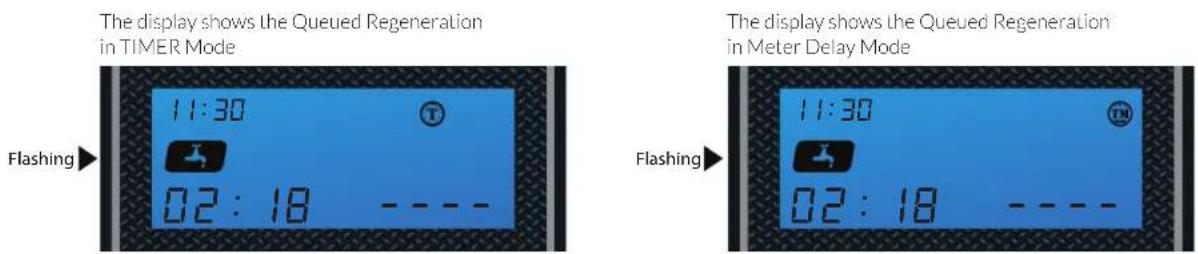
The display shows the Queued Regeneration in TIMER Mode

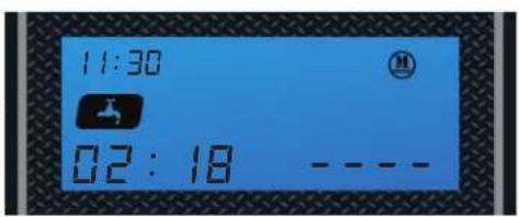
The display shows the Queued Regeneration in Meter Delay Mode
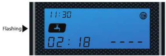
The display shows the Queued Regeneration in Meter Delay Mode.
The system will initiate a regeneration - either the treated water remaining counts down to zero or the remaining time counts down to zero, whichever is first.

Alternating Display
Flashing
5. Manual regeneration
Immediate Regeneration
When the valve is in service position, press and hold the button for 5 seconds, an immediate regeneration will be initiated.
Examples:
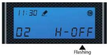
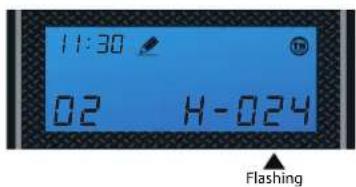
"BW" Flashing (ready to "Backwash")
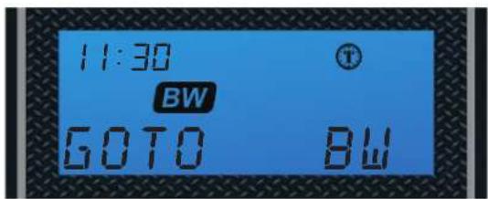

When the time counts down to zero or press the button


"BD" Flashing (ready to "brine")

Stop Regenerating
When regenerating, press the ▼ (▲) simultaneously, then stop regenerating the display will return to the service position.
The display shows as:
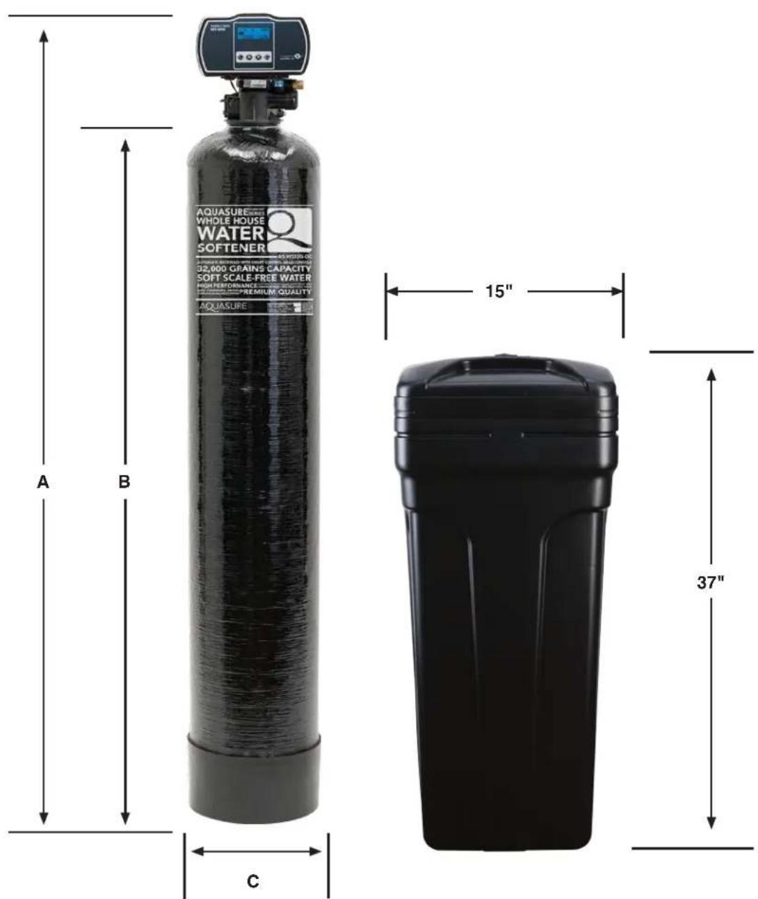
PRODUCT DIMENSION
VALVE DIMENSIONS
| Aquasure Water Softeners | ||||
| Model Tank Size A B C | ||||
| AS-HS32D 9"x48" 58" 50" 9" | ||||
| AS-HS48D 10"x54" 64" 56" 10" | ||||
| AS-HS64D 12"x52" 62" 54" 12" | ||||
SYSTEM TROUBLESHOOT
| Problem Cause Correction | ||
| 1) The control fails to Regenerate automatically | A) Disconnected meter cable A) Reconnect the meter cable | |
| B) Transformer damaged B) Replace the transformer | ||
| C) Electronic controller or sensor damaged C) Replace or repair | ||
| 2) Regeneration at wrong time | A) Timer improperly set, due to power failure A) Reset timer | |
| 3) loss of capacity A) Increase draw water hardness A) reset unit to the new capacity | ||
| B) Brine concentration or quantity | B) Keep brine tank full of salt at all times. Clean it yearly. Salt may be bridged. If using a salt grid Plate insure refill water is over it | |
| C) Rinse fouling C) Consolidate the rinse tank, clean the rinse and prevent future fouling | ||
| D) Poor distribution, channeling (Uneven bed service) | D) Check distributors and backwash flow | |
| E) Internal control leak E) Replace the spacer, seal or piston | ||
| F) Aging of rinse F) Check for resin oxidation caused by Chlorine. Mushy resin | ||
| G) Loss of rinse G) Check for correct bed depth | Broken distributors. Air or gas in bed: Well gas Eliminator loose brine line | |
| 4) Poor water quality | A) Check items listed in Problem # 3 | A) Check items listed in Correction # 3 |
| B) Bypass is open | B) Close the bypass | |
| C) Channeling | C) Check for too slow or high service flow | |
| 5) Excessive salt use | A) High salt setting | A) adjust salt setting |
| B) Excessive water in brine tank | B) refer to problem # 7 tank | |
| 6) Loss of water pressure | A) Fouling of inlet pipe | A) Clean or replace the pipeline |
| B) Fouled resin | B) Clean the resin. Pretreat to prevent | |
| C) Improper backwash | C) Too many resin fines. Reset the flow rate and time of backwash | |
| 7) Excessive water in brine tank | A) Plugged drain line | A) Check drain line and clean flow control |
| B) Brine valve plugged or damaged | B) Clean or replace the brine valve | |
| C) Injector plugged | C) Clean injector, replace injector screen | |
| D) Low inlet water pressure | D) Increase water pressure to allow injector to perform properly | |
| 8) Softener fails to brine draw | A) Plugged drain line | A) Clean drain line and flow control |
| B) Plugged injector | B) Clean or replace the injector and screen | |
| C) No water in the brine tank | C) Check for restriction in B.L.F.C. Ensure Safety float is not stuck | |
| D) Low water pressure | D) Increase water pressure | |
| E) Brine line injects air during brine draw | E) Check brine line for air leaks | |
| F) Internal control leak F) Check seal, spacer and piston for scratches and dents | ||
| 9) Control cycles continuously | A) Faulty timer | A) Replace timer |
| 10) Continuous flow to drain | A) Foreign material in the control | A) Call dealer. Clean valve, rebuild unit |
| B) Internal control leak | B) Same as above | |
| C) Piston jammed in brine or back wash position | C) Same as above | |
LIMITED PRODUCT WARRANTY
Aquasure warrants that your new water conditioner is built of quality material and workmanship. When properly installed and maintained, it will give years of trouble free service.
Five Year Valve, Electronics and Resin Guarantee
Aquasure will replace any part on the valve or electronics which fails or the softening resin within (5) five years from date of manufacture, as indicated by the serial number, provided the failure is due to a defect in material or workmanship. The only exception shall be when proof of purchase or installation is provided and then the warranty period shall be from the date thereof. Resin and internal control valve parts will not be covered for systems used to remove iron, manganese or with very high chlorine concentrated feed waters.
Ten Year Warranty on Resin Tank and Brine Tank
Aquasure will provide a replacement resin tank or brine tank to any original equipment purchaser in possession of the Aquatrol water softener that fails for (10) ten years after the date of purchase, provided that it is at all times operated in accordance with specifications and not subject to freezing.
General Provisions
Aquasure assumes no responsibility for consequential damage, labor or expense incurred as a result of a defect or for failure to meet the terms of these guarantees because of circumstances beyond our control. Installation workmanship failure is not covered under warranty. Damage caused by environmental conditions such as, lightening strikes, humidity or heat will not be covered under warranty.
These warranties are in lieu of all other warranties expressed or implied, and we do not authorize any person to assume for us any other obligation on the sale of this water conditioner. No responsibility is assumed for delays or failure to meet these warranties caused by strike, government regulations or other circumstances beyond the control of Aquasure.
Obtaining Warranty Coverage or General Inquiries
If coverage is available, you may obtain coverage under this Limited Product Warranty by providing Aquasure with proof of original purchase, and that you are the original purchaser. For service under this Limited Product Warranty, you must notify Aquasure by phone at 1-800-661-0680, by email at support@aquasureusa.com, or in writing at 12403 Central Ave. #536, Chino, CA 91710-2604. In making the claim, please provide your name, address, phone number, a description of the product involved, and an explanation of the defect.
SOME STATES DO NOT ALLOW THE EXCLUSION OR LIMITATIONS OF INCIDENTAL OR CONSEQUENTIAL DAMAGES SO THE ABOVE LIMITATION MAY NOT APPLY TO YOU. THIS WARRANTY GIVES YOU SPECIFIC LEGAL RIGHTS, AND YOU MAY ALSO HAVE OTHER RIGHTS WHICH VARY FROM STATE TO STATE. THIS WARRANTY MAY BE TRANSFERRED TO A SUBSEQUENT OWNER WITH WRITTEN APPROVAL OF AQUASURE AND PAYMENT OF STANDARD TRANSFER FEE.


- TABLE OF CONTENT
- INSPECTION & PREPARATION
- INSTALLING THE SYSTEM
- FEATURE & DISPLAY
- PRODUCT DIMENSION
- SYSTEM TROUBLESHOOT
- LIMITED PRODUCT WARRANTY
- WELCOME
- INSPECTION & PREPARATION
- Understanding How The Water Softener Works
- Be Familiar with the System Before Installation
- Inspect the System
- System Components Breakdown (See Dia. A)
- Required Tool List for System Installation
- Required Components not Included with the System
- System Operation Parameter and Installation checklist
- Water Temperature Parameter
- Water Pressure Parameter
- Chlorine & Chloramine Tolerance
- Pre-install environment checklist
- Installation Safety Guide
- INSTALLING THE SYSTEM
- STEP 1. Shutting off the Main Water Supply Valve
- STEP 2. Softener Preparation
- STEP 3. Connecting the System
- NOTE:
- Setting Button
- Up / Down Buttons
- Cycle Button
- STEP 5. Programming Unit
- Setting Time of Day
- Set the hour
- Set the minutes
- Setting the Regeneration Mode
- Choose Between Time, Meter Immediate or Meter Delayed
- Setting the Unit Capacity (Not shown if Timer Mode was selected in 2nd Step)
- Set Unit Measurement - Gallons, Liters or Cubic Meters
- Regeneration Time and Hours Override
- Timer Mode
- Setting the Back Wash Time
- Setting the Brine Time
- Setting the Rapid Rinse Time
- Setting the Water Filling Time
- TOTAL GALLONS CALCULATION
- CONGRATULATION!
- FEATURE & DISPLAYS
- Display in Service
- Timed Regeneration Mode
- Meter Immediate Regeneration Mode
- Meter Delay Regeneration Mode
- Backlight Screen
- Memory during power failure
- Restore factory settings
- Manual regeneration
- Immediate Regeneration
- Examples:
- Stop Regenerating
- PRODUCT DIMENSION
- SYSTEM TROUBLESHOOT
- LIMITED PRODUCT WARRANTY
- Five Year Valve, Electronics and Resin Guarantee
- Ten Year Warranty on Resin Tank and Brine Tank
- General Provisions
- Obtaining Warranty Coverage or General Inquiries
Brand : Aquasure
Model : Harmony AS-HS48D
Category : Water Softener