
DNR-202L - Video recorder D-LINK - Free user manual and instructions
Find the device manual for free DNR-202L D-LINK in PDF.


| Product Type | Network Video Recorder (NVR) |
| Brand | D-Link |
| Model | DNR-202L |
| Video Formats | H.264, MPEG4, MJPEG (live); JPEG (still images) |
| Audio Support | G.711, G.726 |
| Number of Camera Channels | Up to 4 |
| Recording Performance | 32 Mbps |
| Playback Performance | Max 720p for 1 channel; 640x480 for 4 channels |
| Storage | 2 x USB 2.0 ports for external HDD (up to 2 drives) |
| Network Interface | 10/100 BASE-TX Fast Ethernet (RJ45) |
| Network Protocols | IPv4, ARP, TCP, UDP, ICMP, DHCP, DNS, HTTP, HTTPS, SMTP, RTP, RTCP, RTSP, NTP, UPnP |
| Power Adapter | 12V DC, 1.5A (Model AMS3-1201500FU) |
| Power Consumption | 8.5W ±5% (including 2 x 2.5" HDD) |
| Weight | 90 g |
| Operating Temperature | 0 to 40 °C |
| Storage Temperature | -20 to 70 °C |
| Humidity | 10% to 90% non-condensing (operating) |
| Remote Access | Via mydlink portal, web browser, or mobile app (iOS/Android) |
| Event Management | Motion detection, digital input, connection loss; email notifications, buzzer |
| PTZ Control | Yes (if camera supports) |
| Maintenance | Unplug before cleaning; use dry cloth; avoid liquids |
| Safety | Use only approved power supply; keep away from water; do not disassemble |
| Spare Parts / Repairability | No user-serviceable parts; external USB HDDs replaceable; reset to factory defaults via button |
Frequently Asked Questions - DNR-202L D-LINK
User questions about DNR-202L D-LINK
0 question about this device. Answer the ones you know or ask your own.
Ask a new question about this device
Download the instructions for your Video recorder in PDF format for free! Find your manual DNR-202L - D-LINK and take your electronic device back in hand. On this page are published all the documents necessary for the use of your device. DNR-202L by D-LINK.
USER MANUAL DNR-202L D-LINK
natural_image
Exterior view of a black and silver electronic device labeled 'DLink' with a blue circular icon on the front (no additional text or symbols visible)User Manual
mydlink Camera Video Recorder
DNR-202L
Preface
D-Link reserves the right to revise this publication and to make changes in the content hereof without obligation to notify any person or organization of such revisions or changes. Information in this document may become obsolete as our services and websites develop and change.
Manual Revisions
| Revision Date Description | |
| 2.0 March 13, 2015 Revision A2 with firmware version 2.00 | |
Trademarks
D-Link and the D-Link logo are trademarks or registered trademarks of D-Link Corporation or its subsidiaries in the United States or other countries. All other company or product names mentioned herein are trademarks or registered trademarks of their respective companies.
Copyright © 2015 D-Link Corporation.
All rights reserved. This publication may not be reproduced, in whole or in part, without prior expressed written permission from D-Link Corporation.
Table of Contents
Product Overview......4
Package Contents......4
Introduction 5
System Requirements....5
Features......6
Hardware Overview....7
Assembly and Installation 8
Attaching External Drives....8
Installation and Setup....9
HDD Viewer Software Installation 15
HDD Viewer Software Interface....16
View Recording....17
mydlink Portal 18
NVR Status Icons....19
Settings....20
Live Video 21
Playback....22
View Recording 23
Status 24
NVR Info 25
mydlink View - NVR App....26
First Use - Select Your Device 27
Live View....27
Video Playback 30
Video Playback Control ....31
Configuration....32
Using the Configuration Interface....32
Live Video 33
Playback....37
Setup Wizard 43
Setup 46
Network Setup....46
Audio and Video....47
Recording Schedule....48
E-mail Settings....49
Event Settings....50
Log 51
Maintenance 52
Display and Language 52
User Account 53
System 54
Time and Date....55
Firmware Upgrade....56
Hard Drive ....57
Camera Search....58
Help 60
LED and Buzzer Overview....61
Technical Specifications....62
Regulatory Information 64
Product Overview Package Contents

natural_image
Gray-scale icons showing electronic devices including a hard drive, cable, CD, and storage unit (no text or symbols)DNR-202L mydlink Camera Video Recorder
Power adapter
CAT5 Ethernet cable
Quick Installation Guide
CD-ROM with User Manual and software
If any of the above items are missing, please contact your reseller.
Note: Using a power supply with a different voltage than the one included with your product will cause damage and void the warranty for this product.
Introduction
Congratulations on your purchase of the DNR-202L mydlink™ Camera Video Recorder.
The DNR-202L is a wired Network Video Recorder (NVR) that supports up to four network cameras with M-JPEG, MPEG4, or H.264 recording with up to two attached USB hard drives. Thanks to the powerful embedded system, the NVR can record video from network cameras located in local or remote sites to dedicated disk storage without needing a PC.
Powered by mydlink technology, the DNR-202L can be easily setup for Internet access. It supports real-time monitoring and playback from anywhere via an Internet browser. Users can simultaneously record while viewing live feeds or while searching recordings for playback. Complete video management, live surveillance, and playback ability makes the DNR-202L a convenient and stable video recording solution.
System Requirements
- Computer with Microsoft Windows 8 ^ , Windows 7, Vista ^ , XP, or Mac OS 10.7 or above
- PC with Pentium 4 – 2.4 GHz or above, at least 512 MB RAM
- Internet Explorer 8 and above, Firefox, Chrome, Safari 5 or above
• Existing 10/100 Ethernet-based network - Broadband Internet connection
Features
Comprehensive IP Surveillance Solution
- Total Solution: The D-Link DNR-202L is a Network Video Recorder (NVR) capable of 24/7 recording without requiring a PC. The DNR-202L can manage multiple network cameras, provide direct access to view live video and play recorded video files through the Internet from anywhere, anytime. The device itself is lightweight and compact in size for maximum portability.
- Easy to Use: A user-friendly GUI simplifies network and camera setup, allowing users to easily access multiple cameras for viewing, recording, playback, and configuration.
- Centralized Interface for Configuration: The DNR-202L provides a flexible and economic alternative to manage and configure multiple network cameras on a centralized web interface.
- Megapixel Resolution Support: The major advantage of digital over analog video is its higher resolution support. The DNR-202L supports high resolution megapixel recording for vivid video with high clarity.
- Empowered by mydlink Technology: The DNR-202L can be easily setup for Internet access. It supports real-time monitoring and playback from anywhere via an Internet browser.
Powerful Event Management
- Flexible Event Management: Event setup is another key feature of the DNR-202L. The NVR can monitor your cameras for motion detection, digital input, and connection status events to trigger an action.
- Event Notification: One of the most powerful functions is the notification application. The NVR centrally controls the e-mail notifications and can even activate a buzzer function from supported cameras.
Instant Live View
- Full Screen: Enlarge the display to full screen of live view and recorded video.
- Camera Name and Status on OSD: The camera status page will show the connection, recording, frame rate, and bit rate information of each camera. Meanwhile, the time and date are also displayed for quick reference.
- PTZ/Audio Support: Users can control Pan/Tilt/Zoom (PTZ) functions from within the interface using the provided interface buttons.
- Preset Point: Presets from within the interface can be set to instantly restore a previously saved viewpoint.
- Digital Zoom: Videos can be enlarged by using digital zoom.
Intelligent Playback
- AVI Output: During playback, if you uncover video that needs to be exported, you can easily export video in the convenient AVI format.
-
Playback Speed Control: Speed control allows for up to 32x speed fast forward or fast rewind playback. The step playback option displays one frame at a time.
-
Instant Snapshot: Take an instant still image of the video frame during playback.
-
Print Picture: If a printer is connected to the user's PC, the NVR can also print the selected still image.
Hardware Overview
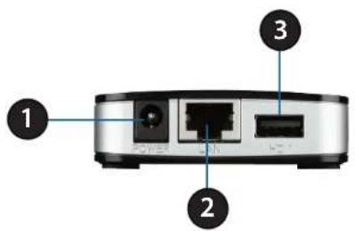
Right View
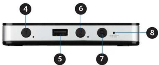
Rear View
| 1 Power Receptor Connect the provided power adapter | |
| 2 Ethernet Port Connect one end of the provided network cable | |
| 3 USB Port for HDD 1 | Attach an external USB Hard Disk Drive (HDD) to this port to save recorded streams |
| 4 HDD 1 Button Press this button to release the HDD attached to the USB Port for HDD 1 | |
| 5 USB Port for HDD 2 Attach an external USB HDD to this port to save recorded streams | |
| 6 HDD 2 Button Press this button to release the HDD attached to the USB Port for HDD 2 | |
| 7 Auto Scan Button Press this button to automatically scan for cameras on the network | |
| 8 Reset Button | Press and hold the recessed button for 10 seconds to reset the device to factory default settings |
Assembly and Installation Attaching External Drives
Step 1
Place the NVR on a non-slip flat surface.
Step 2
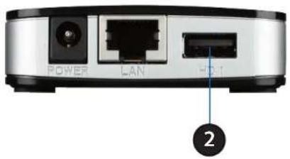
Attach an external USB HDD to the USB HDD1 port. The NVR will mount the HDD and beep once.
Note: When you want to remove an HDD, press and hold the release button for at least three seconds. The NVR will release the HDD and emit a long beep. You can now unplug the USB cable.
Step 3
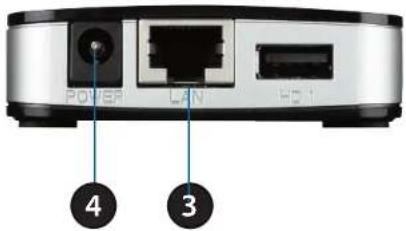
Attach one end of the provided RJ45 network cable to the NVR. Attach the other end to your network. The DNR-202L will test for an Internet connection. Once an Internet connection is established, the blue LED will blink.
Note: If you do not connect an Ethernet cable, the DNR-202L will beep.
Step 4
Attach the provided power adapter.
Installation and Setup
Step 1
Insert the Installation CD-ROM into your computer's optical drive to start the autorun program. Click Start to begin the wizard.
Windows Users:
The CD-ROM will open the Setup Wizard. The Setup Wizard will guide you through the installation process to configure the NVR.
Note:
If the autorun program does not automatically start on your computer, go to Windows and click Start > Run. In the Run command box type D:\autorun.exe, where D: represents your CD-ROM drive.
OS X Users:
Insert the DNR-202L Driver CD in the CD-ROM drive. After you have inserted the CD into your computer, go to the CD drive directory, and double-click the Mac Utility folder to enter.
Step 2
Connect your USB hard drive to the DNR-202L and click Next to proceed.
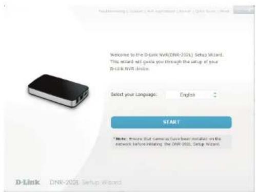
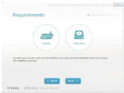
Section 2 - Installation
Step 3
Connect the power adapter to the DNR-202L and then to a power outlet.
Click Next to continue.
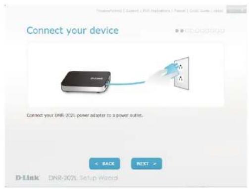
Step 4
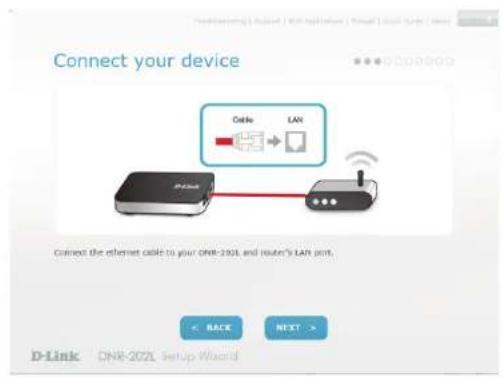
Connect an Ethernet cable from your router's LAN port to the DNR-202L.
Click Next to continue.
Section 2 - Installation
Step 5
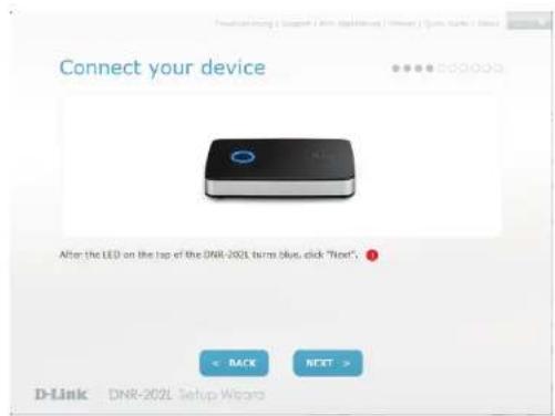
Make sure the LED on the NVR is lit blue then click Next to continue.
Step 6
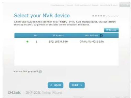
The wizard will attempt to find your NVR in your network. You can click Rescan to search for the DNR-202L at any time.
Click Next to continue.
Section 2 - Installation
Step 7
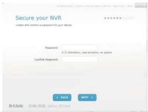
Once your NVR has been found, you can set a password for it in the text boxes.
Click Next to continue.
Step 8
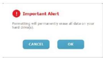
You must format the attached hard drives for the NVR. Make sure you do not have any important data on this drive before clicking Next.
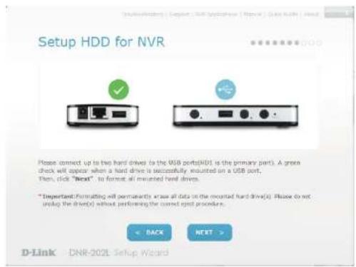
Click OK to proceed with formatting.
Section 2 - Installation
Step 9
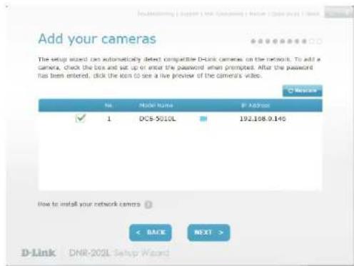
The wizard will scan for all available cameras attached to your network. Registered mydlink cameras will be verified automatically.
You can preview the discovered cameras by clicking on the blue camera icon, or click Next to continue.
Step 10
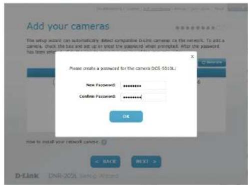
A pop-up will ask you to enter the password for your camera.
Click OK.
The checkbox next to your camera will now have a green checkmark to indicate it has been added successfully.
Click Next to continue.
Note: It is strongly advised to set up passwords for all of your cameras.
Section 2 - Installation
Step 11
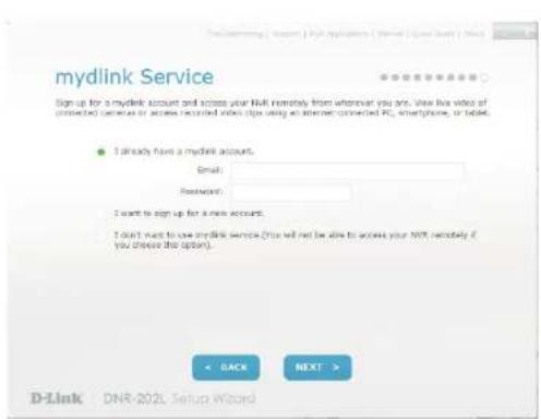
The wizard will guide you through the process of connecting your NVR to a mydlink account. If you already have a mydlink account, enter the correct configuration information and click Next to continue, otherwise select I want to sign up for a new account or I don't want to use mydlink service and follow the instructions.
Click Next to continue.
Step 12
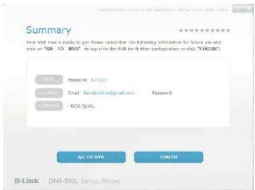
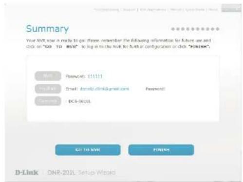
Setup is complete. Make a note of the details presented and click on Go to NVR to log in to the NVR for further configuration (see "Using the Configuration Interface" on page 32) or click Finish.
To add cameras after initial setup, refer to "Camera Search" on page 58.
HDD Viewer Software Installation
Your DNR-202L comes with a convenient application to assist you in managing your recorded video. This section will guide you through the simple setup procedure, and the interface of the application.
Step 1
Attach the hard drive containing the DNR-202L recordings you wish to view.
Step 2
Insert the DNR-202L Driver CD in the CD-ROM drive. Navigate to the D:\HddViewer folder (where D: represents the drive letter of your CD-ROM drive) and double click on the setup program to begin the installation.
Step 3
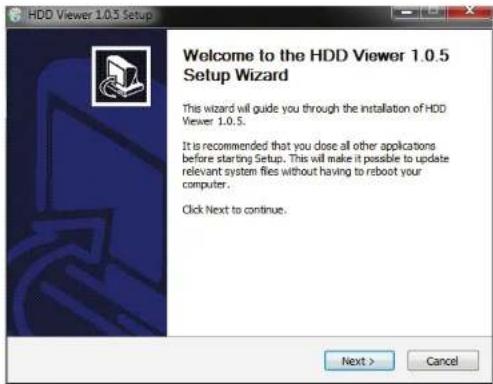
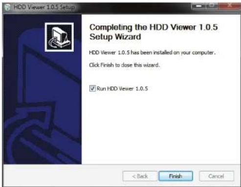
Follow the on-screen prompts and click Finish to complete the installation.
HDD Viewer Software Interface
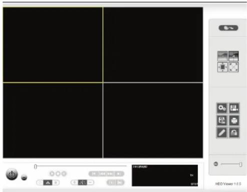
The HDD-Viewer application enables you to view, search and, backup your recorded videos from a simple interface. The interface controls are described below. For advanced users refer to "Playback" on page 37 for more details.
| Open Recording Search Menu | Use this button to show the Open Recording menu. See "View Recording" on page 17 for more. | |
| Display Single feed U | se this button to switch to a single camera feed in the live video display area. | |
| Display 2 x 2 feed | Use this button to switch to a 2 x 2 camera feed in the live video display area. | |
| Actual Size Use this b | button to display the recording in it's native resolution. | |
| Full Screen Use this b | button to switch to a full screen view of the live video feed. | |
| On Screen Display Settings | Use this button to configure the various settings for the on screen display. | |
| Save as AVI Use this b | button to export the video as an AVI file. | |
| Print Image Use option | this to print a still image. | |
| Save as Image Use this | option to save a still image. | |
| Image Enhancement | Use this option to apply image enhancements. | |
| Backup Data Use this | option to make a backup your video recordings. | |
| Volume Use the slider | to adjust the playback volume. | |
| Close Application Use | this button to close the application. | |
| Minimize Application | Use this button to minimize the application. |
View Recording
Click a highlighted date on the calendar to access the Date-Time Panel and select the video recordings which you would like to review.
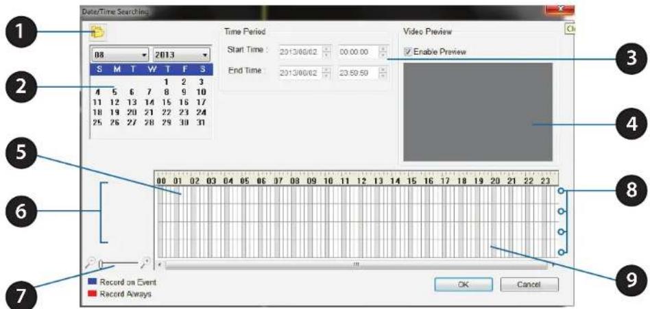
| 1 Select Folder | Use this button to navigate to your video recordings folder. Recordings are stored under the "avdata" folder on your HDD. |
| 2 Date Selection Area | Select the year, month, and day of the recording you wish to view. Dates with recordings available for playback are highlighted in blue. |
| 3 Time Range Selection Select a | beginning and end time for the recording you wish to view. |
| 4 Video Preview When Enable P | review is checked, this area will display a preview. |
| 5 Timeline This timeline will adjust according to the level of zoom selected. | |
| 6 Available Streams This area lists the recording devices available. | |
| 7 Zoom Slider Use the zoom slider control to zoom in and out of the timeline. | |
| 8 Available Recordings | Recordings are graphed below the timeline. Blue bars indicate an event was recorded. Red bars indicate the camera is set to always record. |
| 9 Selected Period | Click within the timeline to select a recording period. |
mydlink Portal
After registering your NVR with a mydlink account in the NVR Setup Wizard, you will be able to remotely access your NVR from the www.mydlink.com website. After you log in to your mydlink account, you will be taken to the My Devices page.
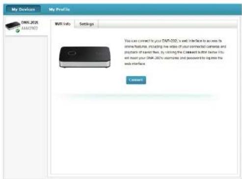
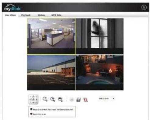
To connect to your NVR click on the Connect button and provide your password to complete the login process. After you have connected to the NVR, you will be taken to the Live Video page. (Refer to "Live Video" on page 21)
NVR Status Icons
Here, you can see the online status of each of your NVRs. Your online status may be one of the following:
A green checkmark indicates that your NVR is online and ready to use.
A yellow exclamation point indicates that your NVR is online, but the NVR password has changed. You will need to enter your new NVR password to access your NVR again.
A red cross indicates that your NVR is offline and currently cannot be accessed remotely.
If your NVR is offline, try the following:
- Check to make sure that the Internet connection to your NVR is working properly.
- Try restarting your Internet router.
- Check your NVR's cable connections and make sure they are secure.
- Check to make sure that the LED on your NVR is lit solid blue.
If you still cannot access your NVR, reset your NVR and run the NVR Setup Wizard again from the CD-ROM included in your package.
Settings
On the Settings tab you can see a general summary of your NVR.
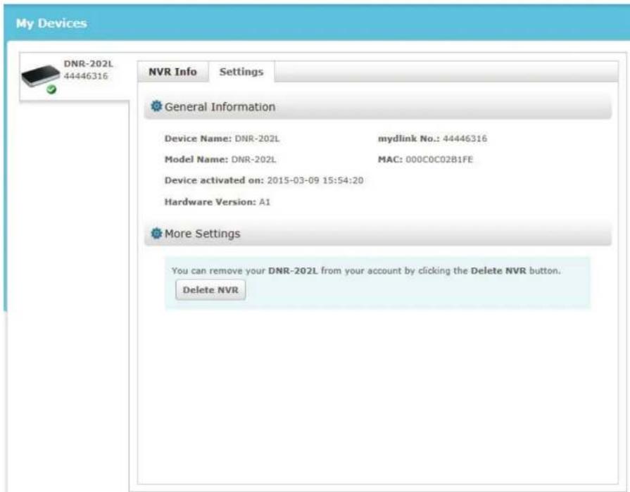
If you wish to remove your NVR from your mydlink account click on the Delete NVR button and provide your password to complete the action.
Live Video
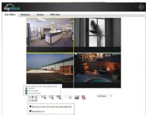
After you have connected to your NVR, the Live Video tab will be selected by default and will display the Live Video feed. You can choose a different camera from the drop-down list, or you can choose to view all the available channels.
A notice is displayed below the controls if any events have been recorded, or if the NVR is currently recording.
The available controls are detailed below.
| Control Pad This control pad can be used to pan, tilt, and zoom (PTZ) a dome camera, or electronically pan, tilt, and zoom (PTZ) within the camera's predefined view area, if one has been defined. | |
| Zoom Control Use the + and - buttons to zoom in or out. | |
| Actual Size Use this control to view video in it's native resolution. | |
| Record Use this control to toggle recording. | |
| Save to Image Use this option to save a snapshot image. | |
| Auto Scan Use this option to view each camera feed one at a time.Select the camera you wish to view from the drop-down list. |
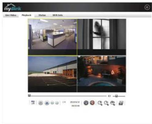
Playback
The Playback tab enables the user to review pre-recorded video. The available playback controls are detailed below.
| Playback Seeker Use | the playback seeker to quickly jump to a specific point in the recording. | |
| Volume Control Adjust | st the slider to increase or decrease the audio volume. | |
| Open Recording Click | on this control to open the saved recordings search dialog. See "View Recording" on page 17. | |
| Pause Playback Use this | control to pause the current playback. | |
| Stop Playback Use this | control to stop the current playback. | |
| Step Back/Forward Use | these controls to pause playback and either step back one frame or advance forward by one frame. | |
| Speed Down/Up Use | these controls to slow down or speed up the playback. | |
| Zoom Control Use the + and - buttons to zoom in or out. | ||
| Actual Size Use this control to view video in it's native resolution. | ||
| Save to Image Use this option to save a snapshot image. | ||
View Recording
Click a highlighted date in the calendar to access the Date-Time Panel and select the video recordings which you would like to review.
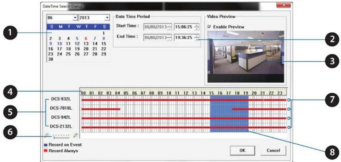
| 1 Date Selection Area | Select the year, month and day of the recording you wish to view. Dates with recordings available for playback are highlighted blue. |
| 2 Time Range Selection Select a | beginning and end time for the recording you wish to view. |
| 3 Video Preview When Enable P | preview is checked, this area will display a preview. |
| 4 Timeline | This timeline will adjust according to the level of zoom selected. |
| 5 Available Streams This area lists the recording devices available. | |
| 6 Zoom Slider | Use the zoom slider control to zoom in and out of the timeline. |
| 7 Available Recordings | Recordings are graphed below the timeline. Blue bars indicate an event was recorded. Red bars indicate the camera is set to always record. |
| 8 Selected Period | Click within the timeline to select a recording period. |
Status
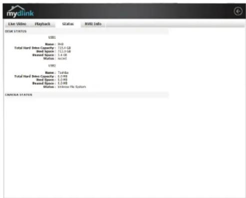
The Status tab describes both USB storage and cameras connected to the NVR.
Name: This shows the name given to the USB storage device attached to the USB 1 or USB 2 port.
Total Hard Drive Capacity: This shows the total amount of storage space available on the USB storage device attached to the USB 1 or USB 2 Port.
Used Space: This shows the used storage space of the USB storage device attached to the USB 1 or USB 2 Port.
Unused Space: This shows the amount of space available for recording on the USB storage device attached to the USB 1 or USB 2 Port.
Status: This shows if the USB storage device attached to the USB 1 or USB 2 port is currently being recorded to.
Camera Status: Clicking on the Camera Status button allows you to access your individual cameras' status information.
NVR Info
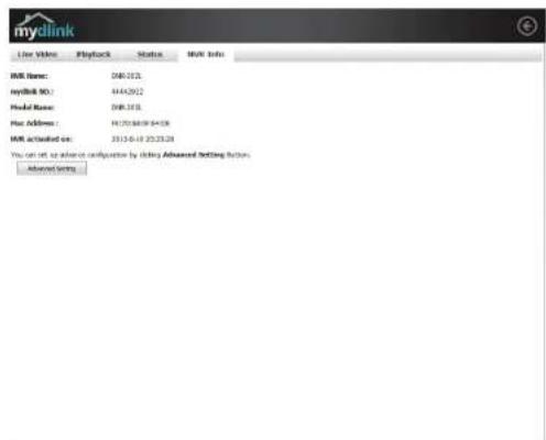
The NVR Info tab shows you various information about your NVR.
NVR Name: The Device Name is a unique name that can help you to identify the NVR. Clicking on the Device Name will open a window for you to login to your NVR's configuration interface.
mydlink No.: Displays the mydlink number of your device.
Model Name: Displays the model name of your device.
MAC Address: Displays the MAC address of your device.
NVR activated on: Displays the time and date that your device was added to mydlink.
Advanced Settings: Clicking on the Advanced Settings button allows you to access your NVR's configuration interface. To open your NVR's configuration interface, select the NVR web page and enter the password.
mydlink View - NVR App
Search for "mydlink View - NVR" to download and install the app on your smartphone or tablet when connected to the Internet.

mydlink View - NVR app requires: iOS version 5.1.1 or above or Android version 4.01 or above.
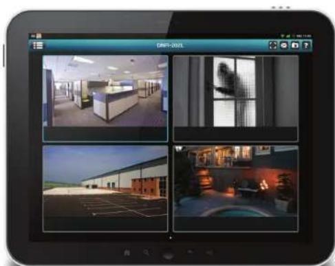
Once the download has been completed, launch the "mydlink View - NVR" app and log in to your mydlink account. Select your DNR-202L from the device list to access the live video from the connected cameras.
Now you can remotely access the live video, playback recorded videos, and manually enable or disable recording.
natural_image
Computer screen displaying four interior photos of an office or campus with visible windows and a person in the room (no text or symbols)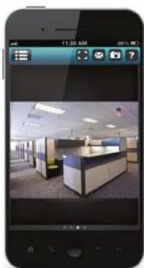
natural_image
Smartphone displaying a photo of an office interior with cubicles and desks (no visible text or symbols)First Use - Select Your Device
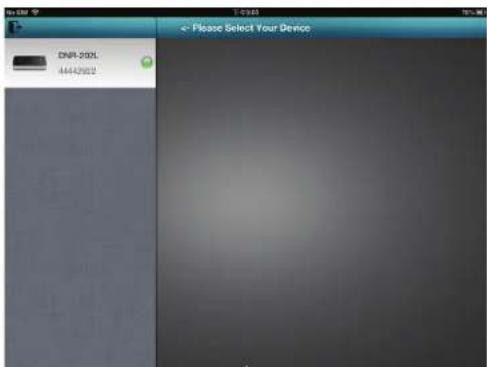
Before using the mydlink View - NVR app for the first time, please ensure to add your DNR-202L to your mydlink account first.
After starting the mydlink View - NVR app, your DNR-202L will be displayed in the My Device list. The app will connect to your DNR-202L, and you can then view live video and playback from your recordings archive via your device.
Live View
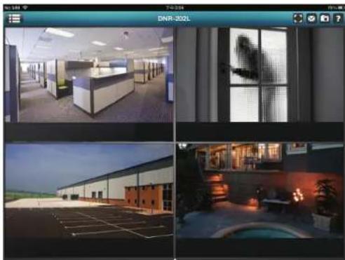
Tap on the DNR-202L icon and the mydlink View-NVR will access the Live video panel.
natural_image
Four-panel collage showing office and interior views: office with desks, large windows, warehouse with parking lot, and modern interior with illuminated fixtures (no visible text or symbols)iPhone/iPod touch Grid View
On an iPhone or an iPod touch, mydlink View-NVR can display the Device List of your mydlink account on the main screen. Tap on your DNR-202L to enter the 4-grid view.
iPad Grid View
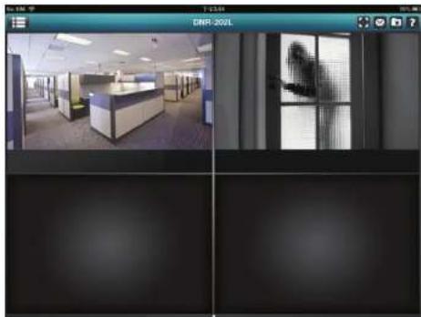
On an iPad, mydlink View-NVR can expand and shrink the Device List of your mydlink account at the left-hand side of the panel. Tap on your DNR-202L to enter the live video view. Double-tap on one of the channels to start a single-channel live video. Double-tap again to return back to the grid view.
natural_image
Interior view of an office with cubicles and a glass door, showing two panels (top: 13:44, bottom: 70% zoom) with no visible text or symbols.Channel selection
- In single channel mode, users can swipe through the video channels to see the previous or the next video channel of the cameras connected to the DNR-202L.
- Double-tap on one of the channels to select a single-channel live video stream.
- Tap on the "My Device" button to return to the Device List of your mydlink account.
natural_image
Glass display table with a gift box, bowl of fruit, and a small object on top (no visible text or symbols)Pan Tilt Zoom (PTZ)
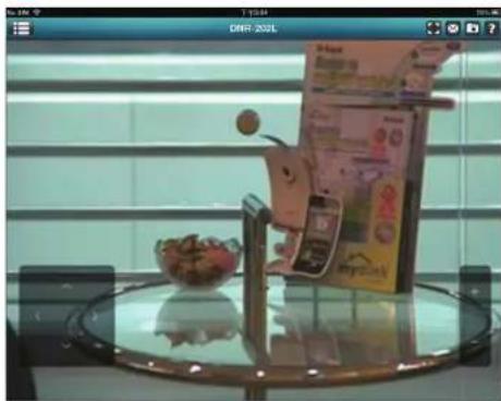
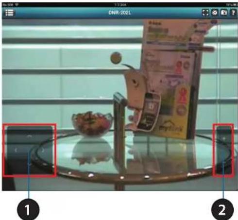
To access PTZ controls, use a two finger tap while streaming a single channel video stream and the PTZ control panel will appear.
Use a two finger tap on the video stream again to disable the PTZ control panel.
| 1 Pan Tilt Control | Tap on the directional arrows to Pan and Tilt the camera |
| 2 Zoom Control Tap the plus or minus button to zoom the camera focus in or out | |
Note: The PTZ control function must be enabled on the camera connected to the DNR-202L in order for mydlink View-NVR to control the PTZ function. See "Live Video" on page 33 for more information.
Video Stretch
In live view or playback archive mode, you can tap on the video stretch button (to) to stretch the video to full screen. Tap the button again to disable stretch.
Note: This function may alter the aspect ratio of the video stream.
Snapshot
While streaming a single channel, tap the Snapshot button () to capture a snapshot. The image will be saved to the device's picture storage area. While viewing video in grid view, tap the Snapshot button () to take snapshots of all the channels. The images will be saved to the device's camera roll.
Note: The saved snapshot will be at the original resolution of the IP camera video.
natural_image
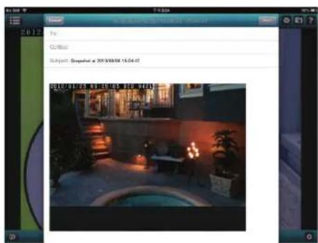
Interior scene with a glass table, a small bowl of food, and a magazine on top (no visible text or symbols)While streaming a single-channel video, tap the e-mail button () to capture a snapshot and insert it into an e-mail. Complete the To, Cc/Bcc fields as required and click Send to send the e-mail with snapshot attached or click Cancel to cancel the operation.
While viewing in grid view, tap the e-mail button () to capture a snapshot of all the channels and insert all the snapshots into a single e-mail. Complete the To, Cc/Bcc fields as required and tap Send to send the e-mail with snapshot attached or tap Cancel to cancel the operation.
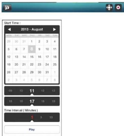
The video playback function is only available in single view mode. Tap the open recording button ☐ while in single channel mode to bring up the playback selection panel.
Use the playback selection panel to scroll through your video recordings archive. Scroll to the date and time you wish to playback, and tap Play.
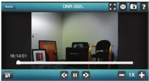
Video Playback Control
While the video recording is playing in single view mode, tap the playback control button (<< >>) to control the direction of the video playback.
The control buttons are:
- Step backward for 1 Second (◀)
- Play/pause toggle ( )
- Step forward for 1 Second (▶)
Use the speed panel ( ) to control the speed of video playback from x1 through to x32 speed.
natural_image
Interior view of a room with chairs and framed pictures, captured in a video player interface (no readable text or symbols)Note: The quality of display performance will vary according to network bandwidth availability.
Configuration Using the Configuration Interface
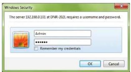
After completing the Setup Wizard, you are ready to use your NVR. The NVR's built-in web configuration utility is designed to allow you to easily access and configure your DNR-202L. At the end of the wizard, click Go to NVR, or enter the IP address of your NVR into a web browser, such as Internet Explorer. To log in, use the username admin and the password you created in the Setup Wizard. If you did not create a password, the default password is blank. After entering your password, click OK.
Step 1
Click Go to NVR to continue to the NVR web configuration page.
Step 2
Enter your NVR credentials to access the configuration interface.
Live Video
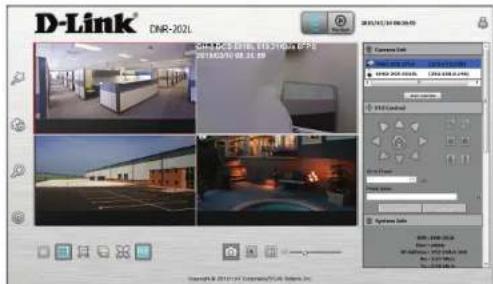
This section shows the NVR's live video feeds. You may select any of the available icons listed below to operate the camera.
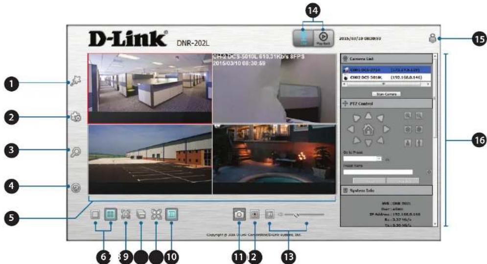
| 1 Wizard | Click this icon to start the NVR Setup Wizard. |
| 2 Settings | This takes you to the advanced settings page where you can manually customize your NVR's network, camera, schedule, events, and maintenance settings. |
| 3 Camera Search | This takes you the camera settings page, where you can add cameras and customize your camera settings. |
| 4 Help | This takes you to the help section in the UI. |
| 5 Channel Windows | You can drag to reposition camera streams or double-click to view one stream. The selected video stream will be marked with a red border. |
| 6 Viewing Modes | Switch between viewing a single camera feed or four camera feeds. |
| 7 Full Screen | Select to display the video on full screen. Press the ESC button on the keyboard to return to normal view. |
| 8 Auto Scan | Activate auto scan to cycle through the channels/cameras on the display. |
| 9 Actual Size | Switch the video to the actual size or fill the window. |
| 10 OSD | Display the information on the video. |
| 11 Snapshot Click this icon to take a snapshot of the active stream. | |
| 12 Manual Record Click to enable or disable recording manually. | |
| 13 Audio | Click to enable or disable audio from the selected camera's microphone (if camera supports audio). When enabled, you can adjust the volume via the slider. |
| 14 Live/Playback Switch between the Live View and the Playback pages. | |
| 15 Log In/Out Click this to log in or out of the NVR. | |
| 16 Info Sections | This section contains various detailed information about the NVR. You can collapse or restore each section for viewing by clicking on the title bar. |
Notes:
- Snapshot: Right-click on the video and select the snapshot function to capture an image immediately.
- Right-clicking on the video will show the option to Switch to Full Screen. Press the ESC button on the keyboard to return to normal view.
- Swap: Right-click on the video and select a channel under Swap to display a different video channel in that window.
Section 5 - Configuration
Camera List:
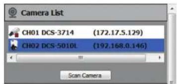
The camera list section displays a list of the currently attached cameras. Select a camera from the camera list on the right and then drag it to the window where you want it to be displayed. Click Scan Camera to update the list of connected cameras.
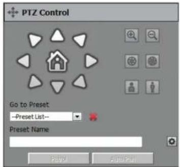
PTZ Control:
| Control Pad This | control pad can be used to pan, tilt, and zoom (PTZ) a dome camera, or electronically pan, tilt, and zoom (PTZ) within the camera's predefined view area, if one has been defined. | |
| Zoom Control Use | the + and - buttons to zoom in or out. | |
| Auto/Manual Focus Use | Use this control to choose between automatic and manual focus control. | |
| Focus Near/Far Use | this control to choose between far or near focus. | |
| Go to Preset Select a preset from the drop-down list to apply it to the camera. | ||
| Preset Name Enter a name for the selected Preset. | ||
| Set as Preset Click | to apply the selected Preset. Once you have set a preset, you can enable Patrol and Auto Pan modes. | |
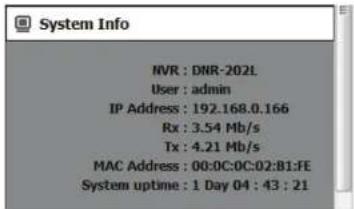
System Information:
The system information section displays basic statistics and details about the NVR server. Click on the title bar to collapse this section.
Section 5 - Configuration
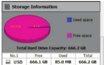
Storage Information:
The storage information section displays details of free space and used space on the attached USB hard drive.
pie
Storage Information | Category | Value | |---|---| | Used space | | | Free space | | | Total Hard Drive Capacity: 666.2 GB | No.1 | Free | Used | Total | | USB | 666.1 GB | 85.0 MB | 666.2 GB |Log:
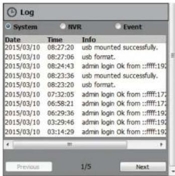
The log section displays detailed messages about your System, NVR, and Events. Click the respective dial to isolate the category and click Previous or Next to navigate between pages.
Playback
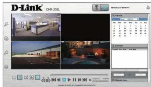
This section shows the NVR's recorded video feeds. You may select any of the available icons listed below to playback, adjust, and export the recorded video streams.
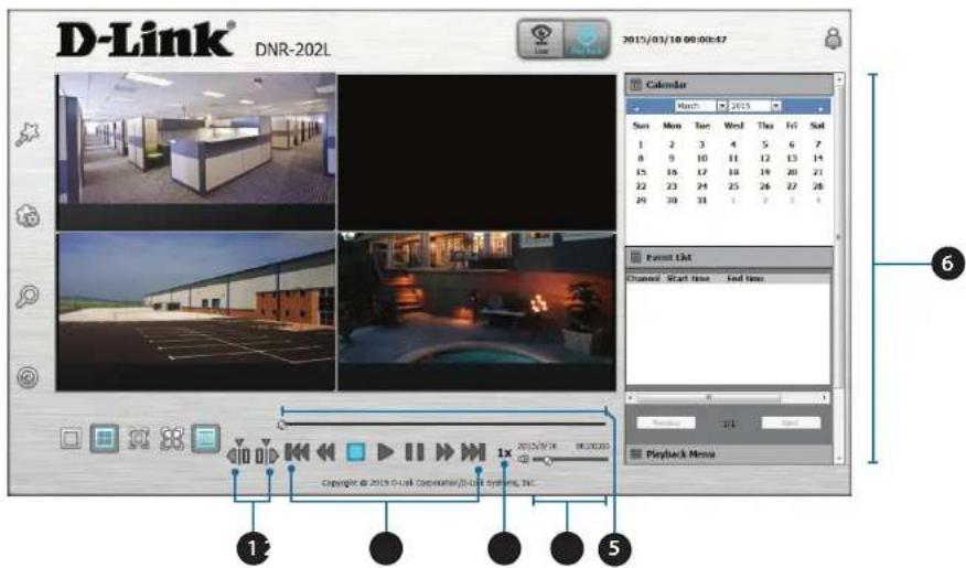
| 1 Cue In/Out | Click these icons to set cue in and cue out points. Indicators will show on the seek bar. |
| 2 Playback Controls | These buttons allow you to Step Backward, Rewind, Play, Pause, Speed Up, and Step Forward the video. Click Rewind or Speed Up more than once to increase the rate of playback. |
| 3 Playback Speed This is the current speed of playback, either forward or in reverse. | |
| 4 Volume Bar | Click on the speaker icon to mute/unmute and use the bar to adjust the volume. |
| 5 Seek Bar You can drag on the bar to jump to any point in the video for playback. | |
| 6 Info Sections | You can see details of recordings in the Calendar, Event List, and Playback Menu sections. |
Section 5 - Configuration
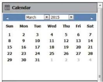
Calendar:
The calendar displays days when recordings were made, as indicated by a highlight. You can navigate to the day, month, and year of your choice. Clicking on a highlighted date will open the View Recorded Files window.
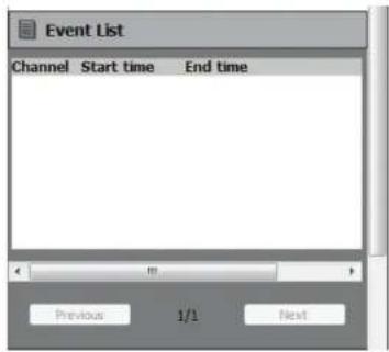
Event List:
The system information section displays basic statistics and details about the NVR server. Click on the title bar to collapse this section.
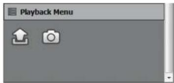
Playback Menu:
| Video Export Click this to open the video export menu to save the video to a file. | |
| Snapshot Click to capture an image of the current video stream and save it. |
Searching Recordings
Click a date to access the View Recorded Files panel and select the video records which you would like to review.
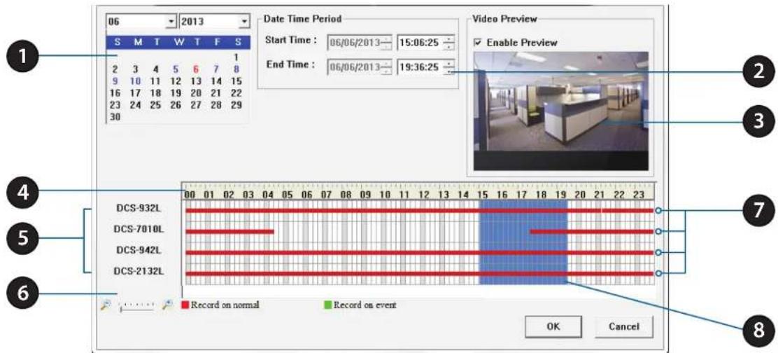
| 1 Date Selection Area | Select the year, month and day of the recording you wish to view. Dates with recordings available for playback are highlighted. |
| 2 Time Period Selection Select a | beginning and end time for the recording you wish to view. |
| 3 Video Preview | When Enable Preview is checked, this area will display a preview. |
| 4 Timeline | This timeline will adjust according to the level of zoom selected. |
| 5 Available Streams This area lists the recording devices available. | |
| 6 Zoom Slider | Use the zoom slider control to zoom in and out of the timeline. |
| 7 Available Recordings | Recordings are graphed below the timeline. Blue bars indicate an event was recorded. Red bars indicate the camera is set to always record. |
| 8 Selected Period | Click within the timeline to select a recording period. |
Section 5 - Configuration
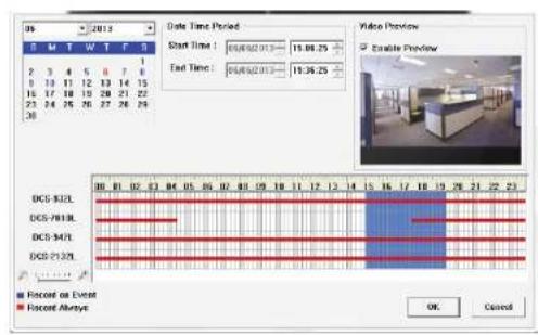
Step 1: From the Date Selection area at the top left of the Date Time panel, select the date you would like to search for the recording. The dates highlighted on the timetable indicate available recorded video records.
Step 2: Colored bars shown in the timeline area differentiate recording types from each other. This will help you select video clips.
Step 3: Select a time period using the Start Time and End Time in the Date Time Period section. Alternatively, select a range from the timeline.
Step 4: Select the Enable Preview option to get a preview of the video you select.
Step 5: Highlight the video clip(s) you would like to review by left-clicking and dragging the time period in the timeline area. The scale of the timeline can be modified using the icon at the bottom left corner.
Step 6: Click the OK button to begin playback.
Save Recording to AVI
After selecting a recording following the steps outlined in "View Recording" on page 17, users can export the video in AVI format.
Step 1: During playback, users can choose the camera from which they would like to save a video clip.
Step 2: Set the cue in and cue out points; the cue in and cue out time will be shown on the information window. Then click the Video Export button.
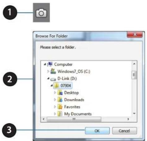
Step 3: Click Browse and choose the folder where you would like to save the file.
Step 4: Select the export options.
Step 5: Click the OK button.
![Export Setting Export Channel Channel 2 Export File Path: Browse Export Format: AVI [Microsoft Video 1] Enable Watermark Enable OSD Start time 2015/3/11.01:29:41 End time 2015/3/11.01:34:28 Video Quality: Good OK Cancel](/content/2026/05/958146/images/8e668ae771432f77fe85579793f9397d165c4549b7a2bf5e75016ecfa201b362.jpg)
Save Snapshot
During playback, users can choose to save an image from a selected camera.
Step 1: Click the Snapshot button when the desired image is shown on the screen.
Step 2: Choose the folder to save the file in.
Step 3: Click OK to save the image to that location.
Setup Wizard
Use this tab if you want to follow the simple steps of the Setup Wizard.
Click the Wizard icon 📁 to begin the Setup Wizard.
Click Next to begin the Setup Wizard.
![Welcome to the DNR-202L Setup Wizard Welcome to the DNR-202L Setup Wizard. This wizard will guide you through setting up your Network Wizard Recorder [NVS]. Begin by clicking the Next button below. Begin 1. Set Password 2. Choose Time Zone 3. Set LAN Connection Type 4. Set Device Name 5. Finish Next Exit](/content/2026/05/958146/images/4f38f6e6ef78c7b255802eb2925787e8cf8eb019194829f224a06dd65cb0f5ea.jpg)
Section 5 - Configuration
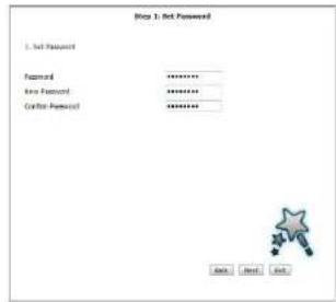
STEP 1: Choose a password for your device.
Click Next to continue.
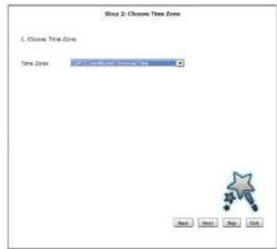
STEP 2: Choose your time zone from the drop-down menu.
Click Next to continue.
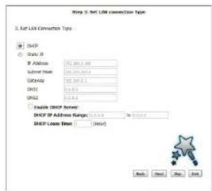
STEP 3: Choose your network connection type.
Select Static IP if your Internet Service Provider has provided you with connection settings, or if you wish to set a static address within your home network.
Note: Select DHCP if you are unsure of which settings to choose.
Click Next to continue.
Section 5 - Configuration
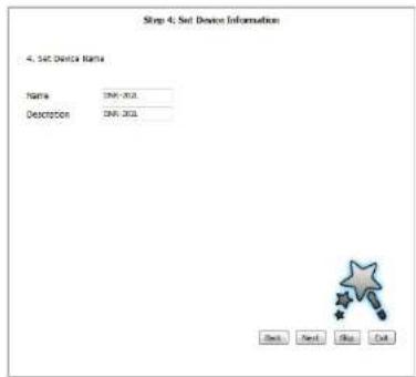
STEP 4: Enter a name and description for your device.
Click Next to continue.
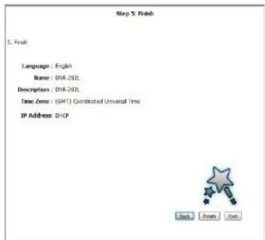
STEP 5: Click Finish to complete the setup process.
Please wait a few moments while the DNR-202L saves your settings.
Setup Network Setup
Click the Setup icon to continue to configure advanced settings manually.
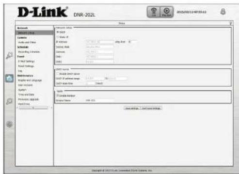
DHCP: Select this connection if you have a DHCP server running on your network and would like a dynamic IP address to be automatically updated to your NVR.
Static IP: You may obtain a static or fixed IP address and other network information from your network administrator for your NVR. A static IP address will simplify access to your NVR in the future.
IP Address: The static IP address.
Subnet Mask: The default value "255.255.255.0" is used to determine if the destination is in the same subnet.
Gateway IP Address: The gateway forwards frames to destinations in a different subnet. Invalid gateway settings may cause the failure of transmissions to a different subnet.
DNS1: Primary domain name server that translates names to IP addresses.
DNS2: Secondary domain name server to backup the primary one.
DHCP Server: Under Static IP, enable or disable the DHCP server. If your network doesn't have a DHCP server, enable NVR DHCP server for easier local network setup. You can configure the DHCP IP address range and DHCP lease time manually.
Apple: Enable Bonjour for multicasting. You can customize the NVR name for identification by Bonjour services.
Audio and Video
This section will allow you to configure and modify the audio and video parameters for each camera.
Step 1: Select the camera which you would like to modify from the camera list. Step 2: NVR will display the parameters for the selected camera. You can modify the parameters for a main and sub profile on this page.
Camera Name: The name of the camera.
Video Format: Select the video format the camera supports.
Frame rate: Select the frame rate.
Resolution: Select the resolution.
Bit rate: Select the bit rate.
Quality: Select the image quality.
Audio: Check the Enable Audio option for live view and recording
Go to Web: Click to connect to the web page of the selected network camera for advanced setup. For example, motion detection should be configured via the camera web interface to enable the NVR to receive the trigger message.
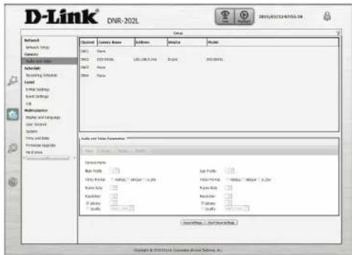
Step 3: Click the Save Settings button.
Note: The system will adjust the frame rate automatically based on the maximum frame rate which that camera can support.
Recording Schedule
On this page, set the recording schedule for automated recording of events.
Enable Scheduled Tick to enable recording by schedule. Recording:
Enable Audio Tick to enable audio recording if supported by the camera. Recording:
Enable Automatic Tick to allow the NVR to overwrite recorded events if there is no Overwrite: more free space on the hard drive.
Pre-record: Select the number of seconds you want the camera to record prior to the event being recorded.
Post-record: Select the number of seconds you want the camera to record after the event is recorded.
Continuous Recording: Select this and drag on the calendar below to specify times for continuous recording.
Record On Event: Select this and drag on the calendar below to specify times for recording only when events occur.
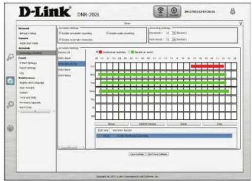
You can also edit the scheduling timetable by click the Always, Add/Edit Schedule, Delete, and Copy buttons. Simply click on a day and then use the buttons to perform an operation.
E-mail Settings
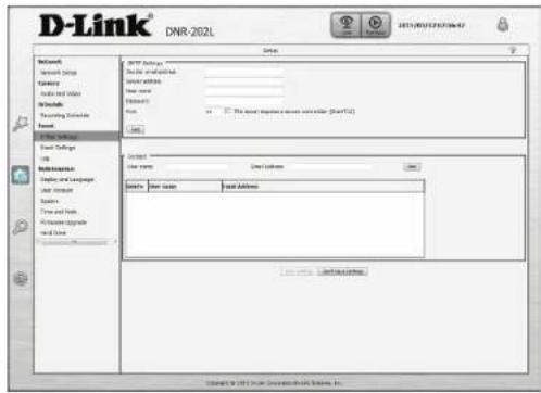
Set the email configuration on this page to receive notifications from the NVR server.
Sender Email Address: Enter the sender's email address.
Server Address: Enter the sender's email server address.
User Name: Enter the Username of the sender account.
Password: Enter the Password of the sender account.
Port: Enter the SMTP port of the sender's server. Check the box if it requires a secure connection.
Test: Click this button to send a test e-mail.
Contact User Name: Enter a username for the recipient.
Contact Email Address: Enter the email address for the recipient. Click Add to add the recipient to the list.
Event Settings
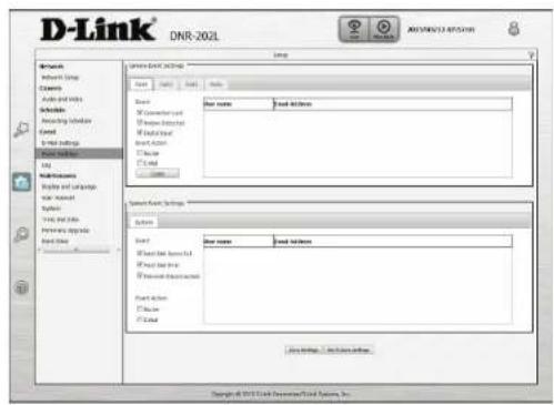
In a typical application, when motion is detected, the DNR-202L sends an alert via e-mail as a notification. For each channel, an event can be triggered by many sources, such as motion detection or digital input. When an event is triggered, a specified action will be performed.
Connection Lost: This option allows you to receive notifications when the connection to this camera is lost.
Motion Detected: This option allows you to receive notifications when motion is detected during camera live video monitoring for this channel.
Digital Input: This option to allow you to receive notifications when an external trigger input is received for this channel.
Buzzer: This option to allow you to receive notifications when a camera loses network connection for this channel.
E-mail: Select this option to have e-mail sent to a specified SMTP account after receiving a camera event. Click Copy to apply event and event actions to specific channels.
Hard Disk Space Full: This option allows you to receive notifications when the hard drive space if full on the attached USB drive.
Hard Disk Error: This option allows you to receive notifications when the attached hard drive has an error.
Network Disconnected: This option allows you to receive notifications when the NVR connection to your network is lost.
Event Action: Enable buzzer and e-mail notifications by checking the corresponding boxes.
Log
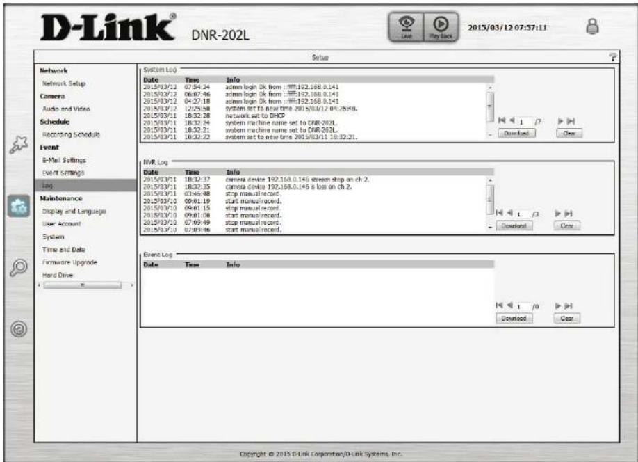
This page displays the system, NVR, and event messages of your NVR. You can click Download to save the logs to a text file and click Clear to delete the logs.
Maintenance Display and Language
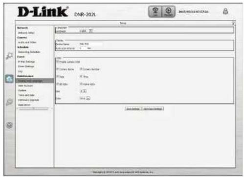
Language: Choose a language for the system menus.
Device Name: Enter the name of the NVR.
Auto Scan Interval: Enter a time for auto-scanning of IP cameras in your network.
Enable Camera OSD: Tick to show the OSD on the stream.
Camera Name: Tick to show the camera name on the OSD.
Camera Number: Tick to show the camera number on the OSD.
Date: Tick to show the date on the OSD.
Time: Tick to show the time on the OSD.
Bit Rate: Tick to show the bit rate on the OSD.
Frame Rate: Tick to show the frame rate on the OSD.
Size: Select from the drop-down the size of the OSD information.
Color: Select the color of the OSD information.
User Account
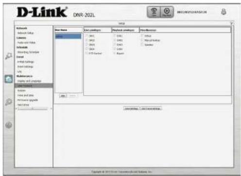
Admin Password Setting: Set a new password for the administrator's account.
Note: Click Save to save the new password.
User Name: All the existing user accounts will be displayed here. You may delete accounts included in the list, but you may want to reserve at least one as a guest account.
Add: Opens up a window to add a new user with an associated password.
Delete: Select a user name from the list and click to delete the account.
Live Privileges: Tick to allow viewing the channels and using PTZ control in live mode.
Playback Privileges: Tick to allow viewing the channels and exporting recorded video in playback mode.
Miscellaneous: Tick to allow the user to use Setup, Manual backup, and Speaker functions.
Note:
The Administrator account can configure all functions of the NVR. This account cannot be deleted. The default password for "admin" is blank. Setting a password after the first login is strongly recommended. If the administrator password is lost, you may hold the reset button on the rear panel of the device to reset the NVR to factory defaults. This will erase all the previously-saved settings.
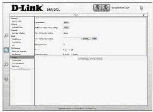
System
System Restart: Click to reboot the NVR.
Restore to Factory Click Restore to reset all configurations to factory default settings. Default Settings:
Save Configuration Save the configuration settings to your computer. Settings:
Load Configuration Browse your computer for configuration settings to be loaded into Settings: the NVR.
Idle Time(Minutes): Set the time in minutes for system idle.
Buzzer: Turn on or off the buzzer.
Enable Auto Plugin: Enable or disable auto plugin.
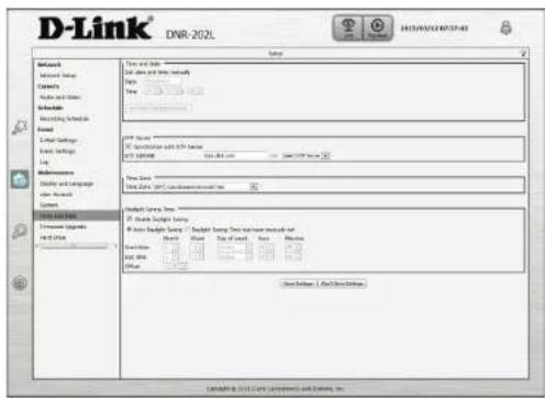
Time and Date
Set Date and Time Manually: Selecting this option allows you to configure the daylight saving date and time manually.
Set Time From My Computer: This uses the time settings from your computer to apply the NVR time settings.
Synchronize with NTP Server: Enable this feature to obtain time automatically from an NTP server.
NTP Server: Network Time Protocol (NTP) synchronizes the DNR-202L with an Internet time server. Choose the one that is closest to your location.
Time Zone: Select your time zone from the drop-down menu.
Enable Daylight Saving: Select this to enable daylight saving time.
Auto Daylight Saving: Select this option to allow your camera to configure the daylight saving settings automatically.
Set Daylight Saving Time This option allows you to set the Daylight Saving Time Manually: manually.
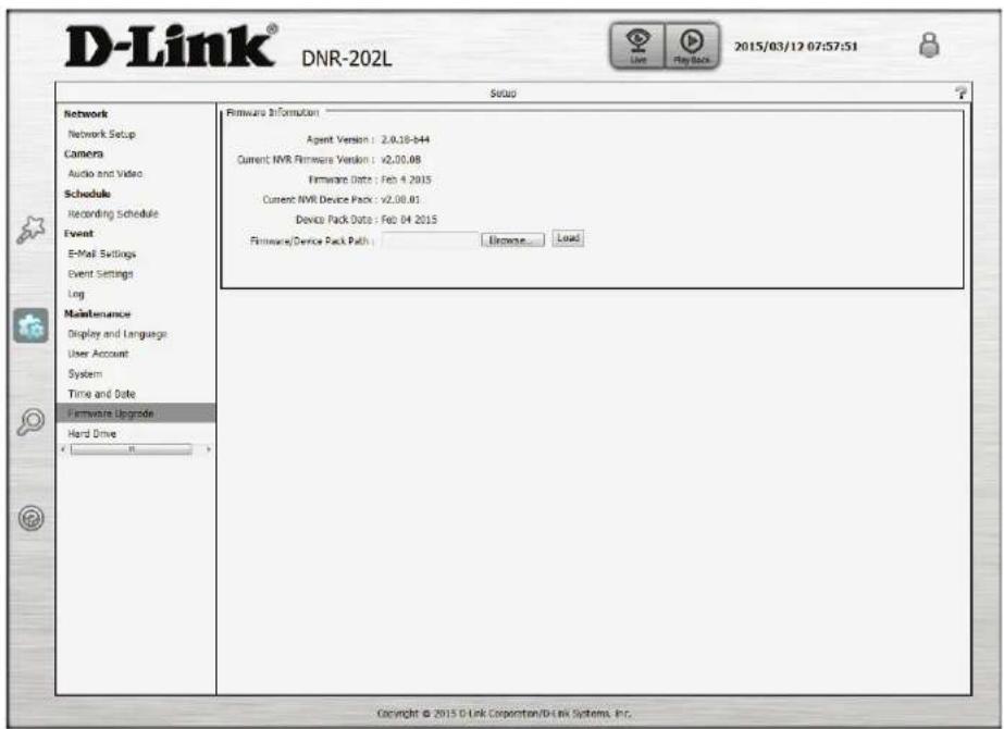
Firmware Upgrade
The device firmware can be upgraded from this page. The firmware update must be saved on the local hard drive of your computer. Click the Browse button to search the local hard drive for the firmware update file. Click Load to upgrade. You may check for firmware updates on the D-Link Support website.
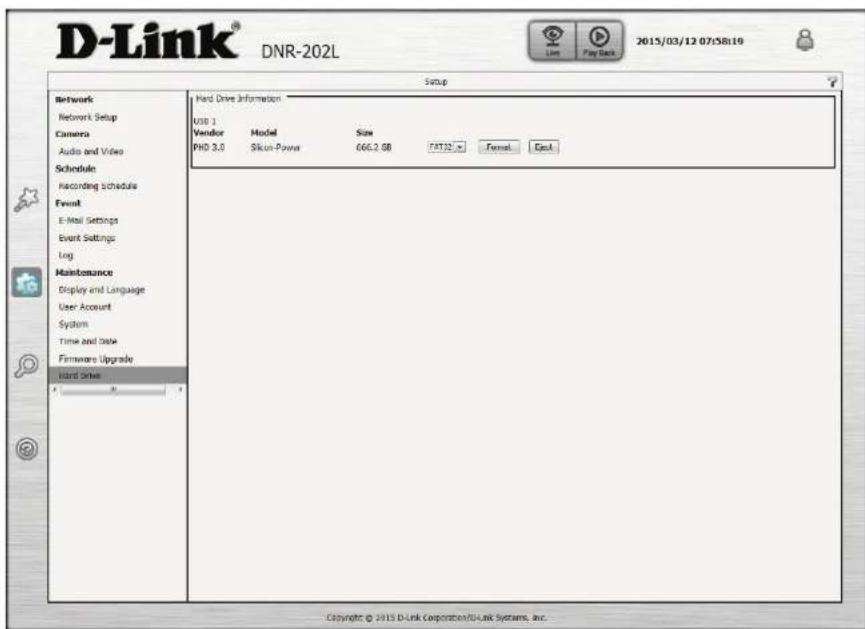
Hard Drive
The section provides users with an overview of the attached USB storage devices, and users can also format and eject attached USB storages devices.
Note: All data will be erased from the attached USB storage device during formatting.
Camera Search
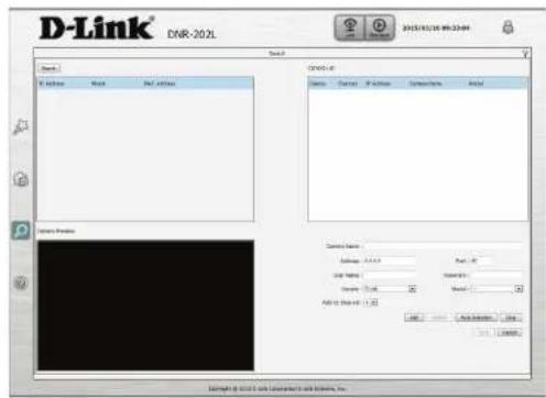
Cameras in your network can be added to your NVR from this page. You can then view camera information and preview the camera's feed. To add cameras, follow the steps below:
Step 1:
Click Search at the top left and the NVR will automatically search for all compatible cameras on the same network. Once it is detected in the top left window, click on the camera to highlight it and its information will be displayed on the bottom right.
Step 2:
Enter the User Name and Password of the selected camera.
Step 3:
Select a channel from the Add to Channel drop-down menu.
Step 4:
Click Add and the selected camera will be added to the Camera List window at the top right.
Step 5:
Click Save to finish adding the camera.
![D-Link® DNR-202L Search Search IP Address MAC Address Camera List Delete Channel IP Address Camera Name Model Camera Preview Camera Name : Address : 0.3.6.4 Port : All low Name Password : Vendor : [type] Node : _ Add To Channel Add Auto Connection Clear Save Cancel Copyright © 2015 B-Link Corporation's Link Systems, Inc.](/content/2026/05/958146/images/033c421ebb2720fb79aee51f3e73bd74418b9145b3aaf786f004649d1e11aa51.jpg)
Camera Name: Enter a name for the camera.
Address: Enter the IP address of the IP camera.
Port: Enter the port used by the IP camera.
User Name: Enter the user name of the IP camera.
Password: Enter the password of the IP camera.
Vendor: Select the IP camera vendor from the drop-down list.
Model: Select the IP camera model from the drop-down list.
Add to Channel: Select the channel from 1-4 that you want the camera to stream to.
Update: Click this button to update changes made to the camera settings.
Auto Detection: Click this button to automatically detect camera information.
Clear: Click this button to clear current camera settings.
Help
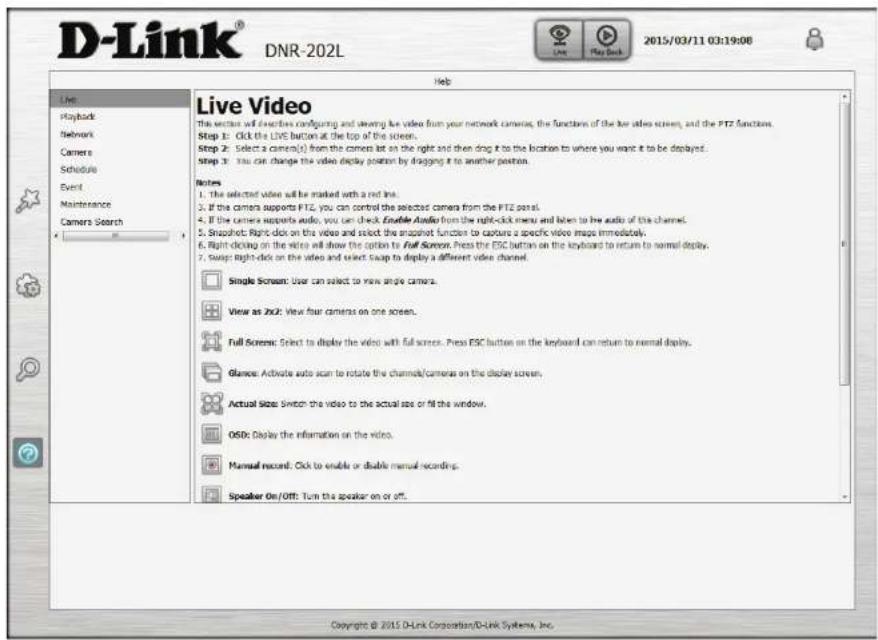
This section describes configuring and viewing live video from your network cameras, the functions of the live video screen, and the PTZ functions.
LED and Buzzer Overview
| LED Color Status Description | |||
| Power & Network LED Red Off Power | down / Link Up | ||
| On Power on | |||
| Blinking Firmware update | |||
| Blue (Network) | Off Network failure | ||
| On Network Link Connected | |||
| Blinking Traffic | |||
| USB1 LED Green Off HDD1 disabled | |||
| On HDD1 enabled | |||
| Blinking Read / Write HDD1 | |||
| USB2 LED Green Off HDD2 disabled | |||
| On HDD2 enabled | |||
| Blinking Read / Write HDD2 | |||
| Key Trigger Method Description | ||
| USB1 button Press button for 3 seconds | Un-mount | HDD1, Buzzer will beep (long). |
| USB1 LED off. | ||
| USB2 button Press key2 for 3 seconds button | Un-mount | HDD2, Buzzer will beep (long). |
| USB2 LED off. | ||
| Auto scan button | Auto scan function- Press scan button for 3 seconds | Start auto scan IP Cameras in local network. |
| Buzzer will beep (long). | ||
| Camera Echo function- Press scan button for 0.5 second Echo | P Camera found (1 beep for 1st camera found, 2 beeps for 2nd, 3 beeps for 3rd, 4 beeps for 4th). | |
| Buzzer will beep (short). | ||
| Reset button | Press reset pin for 10 seconds | Reset to factory default. |
| Buzzer will beep (long). | ||
Technical Specifications
| Technical Specifications | ||
| Network Video Recorder | ||
| Video Format | • H.264/MPEG 4/MJPEG for live streaming | • JPEG for still images |
| Audio support • G.711 • G.726 | ||
| Reset Button • Reset to factory default | ||
| Auto Scan Key • IP Camera Finder (press for 3 seconds) | ||
| External Device Interfaces | • 10/100 BASE-TX Fast Ethernet port | • 2 x USB 2.0 ports for external HDD storage |
| Video Management | ||
| Live View Resolution | • 1280 x 720 (1 channel) | • 640 x 480 (4 channels) |
| Live View Display Modes | • 1 and 4 channels display | |
| Recording Modes | • Schedule, Manual, Event (Motion) | • Continuous |
| Recording Performance | • 32 Mbps | |
| Playback Modes | • Time, Event, Camera | |
| Playback Performance | • Max. 720p for 1 channel | • 640 x 480 (4 channels) |
| Playback Control | • Play, Stop, Pause, Forward, Backward, Next, Previous | |
| Video Export Formats | • AM | |
| Network | ||
| Physical Interface | • RJ45 10/100 LAN Ethernet (auto MDI/MDIX) | |
| Network Protocols | • IPv4, ARP, TCP, UDP, ICMP• DHCP Client• DNS Client• HTTP Server• HTTPS• SMTP | • RTP• RTCP• RTSP• NTP• UPnP |
| Security | ||
| User Management | • Administrator password authentication | |
| Automatic Logoff | • Idle user timeout on configuration pages | |
Appendix B - Technical Specifications
| System | ||
| System Requirements | · Microsoft Windows: XP SP3, Vista, 7, 8 | · Mac OS X 10.7 or later |
| Browser Requirements | · Internet Explorer 8 or higher | · Firefox, Chrome, Safari |
| Mobile Support · Android · iOS | ||
| Remote Management | · Take snapshots/video via web browser | · Configuration interface accessible via web browser |
| System Log · Status of active users · Login history | ||
| Certifications | · CE | · CE LVD |
| · FCC | · C-Tick | |
| Physical | ||
| Weight | · 90 grams | |
| External Power Adapter | · Input: Min 0.5 V / 2.5 A | · Consumption: 8.5 watts ± 5 % (include 2 x 2.5 HDD) |
| Temperature | · Operating: 0 to 40 °C | · Storage: -20 to 70 °C (-4 to 158 °F) |
| Humidity | · Operating: 10% to 90% non-condensing | · Storage: 5% to 95% non-condensing |
| Dimensions | 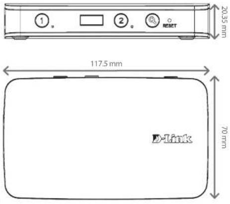 | |
Regulatory Information
Caution: Do not remove the plug and connect it to a power outlet by itself; always attach the plug to the power adapter first before connecting it to a power outlet.
Federal Communication Commission Interference Statement:
This equipment has been tested and found to comply with the limits for a Class B digital device, pursuant to Part 15 of the FCC Rules. These limits are designed to provide reasonable protection against harmful interference in a residential installation. This equipment generates, uses and can radiate radio frequency energy and, if not installed and used in accordance with the instructions, may cause harmful interference to radio communications. However, there is no guarantee that interference will not occur in a particular installation. If this equipment does cause harmful interference to radio or television reception, which can be determined by turning the equipment off and on, the user is encouraged to try to correct the interference by one of the following measures:
- Reorient or relocate the receiving antenna.
- Increase the separation between the equipment and receiver.
- Connect the equipment into an outlet on a circuit different from that to which the receiver is connected.
- Consult the dealer or an experienced radio/TV technician for help.
Non-modifications Statement:
Any changes or modifications not expressly approved by the party responsible for compliance could void the user's authority to operate this equipment.
Caution:
This device complies with Part 15 of the FCC Rules. Operation is subject to the following two conditions: (1) This device may not cause harmful interference, and (2) this device must accept any interference received, including interference that may cause undesired operation.
For product available in the USA/Canada market, only channel 1\~11 can be operated. Selection of other channels is not possible.
This device and its antenna(s) must not be co-located or operating in conjunction with any other antenna or transmitter except in accordance with FCC multi-transmitter product procedures.
Note:
The country code selection is for non-US model only and is not available to all US model. Per FCC regulation, all Wi-Fi product marketed in US must fixed to US operation channels only.
RF Frequency Requirements:
This device is for indoor use only when using all channels in the 5.150-5.250 GHz, 5.725-5.850 GHz frequency ranges. High power radars are allocated as primary users of the 5.150-5.250 GHz, 5.725-5.850 GHz bands. These radar stations can cause interference with and/or damage this device. This device will not operate on channels which overlap the 5600-5650 MHz band. It is restricted in indoor environments only.
IMPORTANT NOTE:
FCC Radiation Exposure Statement:
This equipment complies with FCC radiation exposure limits set forth for an uncontrolled environment. This equipment should be installed and operated with minimum distance 25 cm between the radiator and your body.
Customer Information:
(1) This equipment complies with Part 68 of the FCC rules and the requirements adopted by the ACTA. On bottom of this equipment is a label that contains, among other information, a product identifier of 0. If requested, this number must be provided to the telephone company.
(2) If this equipment 0 causes harm to the telephone network, the telephone company will notify you in advance that temporary discontinuance of service may be required. But if advance notice isn't practical, the telephone company will notify the customer as soon as possible. Also you will be advised of your right to file a complaint with the FCC if you believe it is necessary.
(3) The telephone company may make changes in its facilities, equipment, operations or procedures that could affect the operation of the equipment. If this happens, the telephone company will provide advance notice in order for you to make necessary modification to maintain uninterrupted service.
(4) If you experience trouble with this equipment, you disconnect it from the network until the problem has been corrected or until you are sure that the equipment is not malfunctioning.
(5) Please follow instructions for repairing if any (e.g. battery replacement section); otherwise do not alternate or repair any parts of device except specified.
(6) Connection to party line service is subject to state tariffs. Contact the state public utility commission, public service
commission or corporation commission for information.
(7) If the telephone company requests information on what equipment is connected to their lines, inform them of:
(a) The telephone number that this unit is connected to,
(b) The ringer equivalence number 0
(c) The USOC jack required 0 and
(d) The FCC Registration Number 0
Items (b) and (d) are indicated on the label. The ringer equivalence number (REN) is used to determine how many devices can be connected to your telephone line. In most areas, the sum of the RENs of all devices on any one line should not exceed five (5.0). If too many devices are attached, they may not ring properly.
(8) If your home has specially wired alarm equipment connected to the telephone line, ensure the installation of this equipment does not disable alarm equipment, consult your telephone company or a qualified installer.
Safety Warning:
CAUTION: Risk of Explosion if Battery is replaced by an Incorrect Type. Dispose of Used Batteries According to the Instructions.
Industry Canada Statement:
This device complies with Industry Canada licence-exempt RSS standard(s). Operation is subject to the following two conditions:
(1) this device may not cause interference, and
(2) this device must accept any interference, including interference that may cause undesired operation of the device.
(i) the device for operation in the band 5150-5250 MHz is only for indoor use to reduce the potential for harmful interference to co-channel mobile satellite systems.
Avertissement:
Radiation Exposure Statement
This equipment complies with IC radiation exposure limits set forth for an uncontrolled environment. This equipment should be installed and operated with minimum distance 20 cm between the radiator & your body.
This unit is to be used with a power supply, model AMS3-1201500FU.
Avertissement
CAUTION: Risk of explosion if battery is replaced by an incorrect type. Dispose of used batteries according to the instructions.
This device complies with the essential requirements of the R&TTE Directive 1999/5/EC. For more information, please refer to the Declaration of Conformity.
Notice of Wireless Radio LAN Usage in The European Community:
- At the time of writing this addendum, some countries such as Italy, Greece, Portugal and Spain have not allowed operation of radio devices in the 5 Ghz bands, although operation of 2.4 Ghz radio devices are allowed. Please check with your local authority to confirm.
- This device is restricted to indoor use when operated in the European Community using channels in the 5.15-5.35 GHz band to reduce the potential for interference.
- This device is a 2.4 GHz wideband transmission system (transceiver), intended for use in all EU member states and EFTA countries, except in France where restrictive use applies. This device may not be used for setting up outdoor radio links in France and in some areas the RF output power may be limited to 10mW EIR P in the frequency range of 2454 -2483.5 MHz. For detailed information the end-user should contact the national spectrum authority in France.
This equipment may be operated in AL, AD, BE, BG, DK, DE, FI, FR, GR, GW, IS, IT, HR, LI, LU, MT, MK, MD, MC, NL, NO, AT, OL, PT, RO, SM, SE, RS, SK, ES, CI, HU, CY
Usage Notes:
• To remain in conformance with European National spectrum usage regulations, frequency and channel limitations will be applied on the products according to the country where the equipment will be deployed.
- This device is restricted from functioning in Ad-hoc mode while operating in 5 Ghz. Ad-hoc mode is direct peer-to-peer communication between two client devices without an Access Point.
- Access points will support DFS (Dynamic Frequency Selection) and TPC (Transmit Power Control) functionality as required when operating in 5 Ghz within the EU.
2.4 GHz Wireless Frequency and Channel Operation in EEC Countries:
| Region Frequency Band Max output power (EIRP) | ||
| Metropolitan 2400 - 2454 MHz 100 mW | ||
| Guadeloupe, Martinique, St Pierre et Miquelon, Mayotte | 2454 - 2483.5 MHz 100 mW indoor, 10 mW outdoor | |
| Reunion et Guyane 2400 - 2483.5 MHz 100 mW | ||
| Rest of EU community 2420 - 2483.5 MHz 100 mW |
| R&TTE 1999/5/EC | |||
| WLAN 2.4 - 2.4835 GHz | |||
| IEEE 802.11b/g/n | |||
| Spectrum Regulation MHz, Europa (ETSI) max. EIRP Innenbereich max. EIRP Außenbereich | |||
| Europa 2400 - 2483.5 MHz 100 | mW | 100 mW | |
| Frankreich | 2400 - 2454 MHz | 100 mW | 100 mW |
| 2454 - 2483.5 MHz 100 mW | 10 mW | ||
5 GHz Wireless Frequency and Channel Operation in EEC Countries:
| Allowable 802.11a Frequencies and Channels Countries | |
| 5.15-5.25 GHz(Channels 36, 40, 44, 48) | Liechtenstein |
| 5.15-5.25 Ghz & 5.725-5.875 Ghz(Channels 36, 40, 44, 48, 149, 153, 157, 161, 165, 169) | Austria |
| 5.15-5.35 GHz(Channels 36, 40, 44, 48, 52, 56, 60, 64) | France |
| 5.15-5.35 & 5.47-5.725 GHz(Channels 36, 40, 44, 48, 52, 56, 60, 64, 100, 104, 108, 112, 116, 120, 124, 128, 132, 136, 140) | Denmark, Germany, Iceland, Finland, Netherlands, Norway, Poland, Sweden, Slovenia, Luxembourg, U.K., Ireland, Slovak, Switzerland, Hungary, Italy |
| 5.15-5.35 Ghz & 5.725-5.875 Ghz(Channels 36, 40, 44, 48, 52, 56, 60, 64, 149, 153, 157, 161, 165, 169) | Czech Republic |
European Community Declaration of Conformity:
| Česky [Czech] | D-Link tímto prohlašuje, že tento DNR-202L je ve shodě se základními požadavky a dalšími příslušnými ustanoveními směrnice 1999/5/ES. |
| Dansk [Danish] | Undertegnede D-Link erklærer herved, at følgende udstyr DNR-202L overholder de væsentlige krav og øvrige relevante krav i direktiv 1999/5/EF. |
| Deutsch [German] | Hiermit erklärt D-Link, dass sich das Gerät DNR-202L in Übereinstimmung mit den grundlegenden Anforderungen und den übrigen einschlägigen Bestimmungen der Richtlinie 1999/5/EG befindet. |
| Eesti [Estonian] | Käesolevaga kinnitab D-Link seadme DNR-202L vastavust direktiivi 1999/5/EÜ põhinöuetele ja nimetatud direktiivist tulenevatele teistele asjakohastele sätetele. |
| English | Hereby, D-Link, declares that this DNR-202L is in compliance with the essential requirements and other relevant provisions of Directive 1999/5/EC. |
| Español [Spanish] | Por medio de la presente D-Link declara que el DNR-202L cumple con los requisitos esenciales y cualesquiera otras disposiciones aplicables o exigibles de la Directiva 1999/5/CE. |
| Ελληνική [Greek] | ΜΕ ΤΗΝ ΠΑΡΟΥΣΑ D-Link ΔΗΛΩΝΕΙ ΟΤΙ DNR-202L ΣΥΜΜΟΡΦΩΝΕΤΑΙ ΠΡΟΣ ΤΙΣ ΟΥΣΙΩΔΕΙΣ ΑΠΑΙΤΗΣΕΙΣ ΚΑΙ ΤΙΣ ΛΟΙΠΕΣ ΣΧΕΤΙΚΕΣ ΔΙΑΤΑΞΕΙΣ ΤΗΣ ΟΔΗΓΙΑΣ 1999/5/EK. |
| Français [French] | Par la présente D-Link déclare que l'appareil DNR-202L est conforme aux exigences essentielles et aux autres dispositions pertinentes de la directive 1999/5/CE. |
| Italiano [Italian] | Con la presente D-Link dichiara che questo DNR-202L è conforme ai requisiti essenziali ed alle altre disposizioni pertinenti stabilite dalla direttiva 1999/5/CE. |
| Latviski [Latvian] | Ar šo D-Link deklarē, ka DNR-202L atbilst Direktīvas 1999/5/EK būtiskajām prasībām un citiem ar to saistītajiem noteikumiem. |
| Lietuvių [Lithuanian] | Šiuo D-Link deklaruoja, kad šis DNR-202L atitinka esminius reikalavimus ir kitas 1999/5/EB Direktyvos nuostatas. |
| Nederlands [Dutch] | Hierbij verklaart D-Link dat het toestel DNR-202L in overeenstemming is met de essentiële eisen en de andere relevante bepalingen van richtlijn 1999/5/EG. |
Appendix C - Regulatory Information
| Malti [Maltese] | Hawnhekk, D-Link, jiddikjara li dan DNR-202L jikkonforma mal-ħtigijiet essenzjali u ma provvedimenti oħrajn relevanti li hemm fid-Dirrettiva 1999/5/EC. |
| Magyar [Hungarian] | Alulírott, D-Link nyilatkozom, hogy a DNR-202L megfelel a vonatkozó alapvető követelményeknek és az 1999/5/EC irányelv egyéb előírásainak. |
| Polski [Polish] | Niniejszym D-Link oświadcza, że DNR-202L jest zgodny z zasadniczymi wymogami oraz pozostałymi stosownymi postanowieniami Dyrektywy 1999/5/EC. |
| Português [Portuguese] | D-Link declara que este DNR-202L está conforme com os requisitos essenciais e outras disposições da Directiva 1999/5/CE. |
| Slovensko [Slovenian] | D-Link izjavlja, da je ta DNR-202L v skladu z bistvenimi zahtevami in ostalimi relevantnimi določili direktive 1999/5/ES. |
| Slovensky [Slovak] | D-Link týmto vyhlasuje, že DNR-202L spĺňa základné požiadavky a všetky príslušné ustanovenia Smernice 1999/5/ES. |
| Suomi [Finnish] | D-Link vakuuttaa täten että DNR-202L tyyppinen laite on direktiivin 1999/5/EY oleellisten vaatimusten ja sitä koskevien direktiivin muiden ehtojen mukainen. |
Warning Statement:
The power outlet should be near the device and easily accessible.

Safety Instructions
Please adhere to the following safety guidelines to help ensure your own personal safety and protect your system from potential damage. Any acts taken that are inconsistent with ordinary use of the product, including improper testing, etc., and those not expressly approved by D-Link may result in the loss of product warranty.
Unless expressly approved by an authorized representative of D-Link in writing, you may not and may not permit others to:
- Disassemble or reverse engineer the device or attempt to derive source code (underlying ideas, algorithms, or structure) from the device or from any other information provided by D-Link, except to the extent that this restriction is expressly prohibited by local law.
- Modify or alter the device.
- Remove from the device any product identification or other notices, including copyright notices and patent markings, if any. To reduce the risk of bodily injury, electrical shock, fire, and damage to the device and other equipment, observe the following precautions:
Power Sources
- Observe and follow service markings.
- Do not push any objects into the openings of your device unless consistent with the authorized operation of the device. Doing so can cause a fire or an electrical shock by shorting out interior components.
- The powering of this device must adhere to the power specifications indicated for this product.
- Do not overload wall outlets and/or extension cords as this will increase the risk of fire or electrical shock.
- Do not rest anything on the power cord or on the device (unless the device is made and expressly approved as suitable for stacking).
- Position system cables and power cables carefully; route cables so that they cannot be stepped on or tripped over. Be sure that nothing rests on any cables.
- Operate the device only from the type of external power source indicated on the electrical ratings label.
- To help avoid damaging your device, be sure the voltage selection switch (if provided) on the power supply is set to match the power available at your location.
- Also be sure that attached devices are electrically rated to operate with the power available in your location.
-
Use only approved power cable(s). If you have not been provided a power cable for your device or for any AC -powered option intended for your device, purchase a power cable that is approved for use in your country and is suitable for use with your device. The power cable must be rated for the device and for the voltage and current marked on the device's electrical ratings label. The voltage and current rating of the cable should be greater than the ratings marked on the device.
-
To help prevent an electrical shock, plug the device and peripheral power cables into properly grounded electrical outlets. These cables are equipped with three-prong plugs to help ensure proper grounding. Do not use adapter plugs or remove the grounding prong from a cable. If you must use an extension cable, use a 3-wire cable with properly grounded plugs.
- Observe extension cable and power strip ratings. Ensure that the total ampere rating of all products plugged into the extension cable or power strip does not exceed 80 percent of the ampere ratings limit for the extension cable or power strip.
• To help protect your device from sudden, transient increases and decreases in electrical power, use a surge suppressor, line conditioner, or uninterruptible power supply (UPS). - Do not modify power cables or plugs. Consult a licensed electrician or your power company for site modifications. Always follow your local/national wiring rules.
- When connecting or disconnecting power to hot-pluggable power supplies, if offered with your device, observe the following guidelines.
• Install the power supply before connecting the power cable to the power supply. - Unplug the power cable before removing the power supply.
- If the system has multiple sources of power, disconnect power from the device by unplugging all power cables from the power supplies.
Servicing/Disassembling
- Do not service any product except as expressly set forth in your system documentation.
- Opening or removing covers that are marked with the triangular symbol with a lightning bolt may expose you to an electrical shock. Only a trained service technician should service components inside these compartments.
• To reduce the risk of electrical shock, never disassemble this device. None of its internal parts are user-replaceable; therefore, there is no reason to access the interior. - Do not spill food or liquids on your system components, and never operate the device in a wet environment. If the device gets wet, see the appropriate section in your troubleshooting guide or contact your trained service provider.
- Use the device only with approved equipment.
- Move products with care; ensure that all casters and/or stabilizers are firmly connected to the system. Avoid sudden stops and uneven surfaces.
Environment
- Do not use this device near water (e.g. near a bathtub, sink, laundry tub, fish tank, in a wet basement or near a swimming pool).
-
Do not use this device in areas with high humidity.
-
This device must not be subjected to water or condensation.
- Keep your device away from radiators and heat sources. Also, do not block cooling vents.
Cleaning
• Always unplug the power before cleaning this device.
- Do not use liquid or aerosol cleaners of any kind. Use only compressed air that is recommended for electronic devices.
- Use a dry cloth for cleaning.
Protecting Against Electrostatic Discharge
Static electricity can harm delicate components inside your system. To prevent static damage, discharge static electricity from your body before you touch any of the electronic components, such as the microprocessor. You can do so by periodically touching an unpainted metal surface on the chassis.
You can also take the following steps to help prevent damage from electrostatic discharge (ESD):
- When unpacking a static-sensitive component from its shipping carton, do not remove the component from the antistatic packing material until you are ready to install the component in your system. Just before unwrapping the antistatic packaging, be sure to discharge static electricity from your body.
- When transporting a sensitive component, first place it in an antistatic container or packaging.
- Handle all sensitive components in a static-safe area. If possible, use antistatic floor pads, workbench pads, and an antistatic grounding strap.
Environmental
This product may contain a battery. Recycle or dispose of batteries in accordance with the battery manufacturer's instructions and local/national disposal and recycling regulations. For more information, please refer to the warranty guide.
Disposing of and Recycling Your Product
ENGLISH

This symbol on the product or packaging means that according to local laws and regulations this product should be not be disposed of in the household waste but sent for recycling. Please take it to a collection point designated by your local authorities once it has reached the end of its life, some will accept products for free. By recycling the product and its packaging in this manner you help to conserve the environment and protect human health.
D-Link and the Environment
At D-Link, we understand and are committed to reducing any impact our operations and products may have on the environment. To minimise this impact D-Link designs and builds its products to be as environmentally friendly as possible, by using recyclable, low toxic materials in both products and packaging.
D-Link recommends that you always switch off or unplug your D-Link products when they are not in use. By doing so you will help to save energy and reduce CO2 emissions.
To learn more about our environmentally responsible products and packaging please visit www.dlinkgreen.com
DEUTSCH
DE

- User Manual
- mydlink Camera Video Recorder
- Preface
- Manual Revisions
- Trademarks
- Table of Contents
- Product Overview......4
- Assembly and Installation 8
- mydlink Portal 18
- Configuration....32
- LED and Buzzer Overview....61
- Technical Specifications....62
- Regulatory Information 64
- Product Overview Package Contents
- Introduction
- System Requirements
- Features
- Comprehensive IP Surveillance Solution
- Powerful Event Management
- Instant Live View
- Intelligent Playback
- Hardware Overview
- Assembly and Installation Attaching External Drives
- Step 1
- Step 2
- Step 3
- Step 4
- Installation and Setup
- Windows Users:
- Note:
- OS X Users:
- Section 2 - Installation
- Step 5
- Step 6
- Step 7
- Step 8
- Step 9
- Step 10
- Step 11
- Step 12
- HDD Viewer Software Installation
- HDD Viewer Software Interface
- View Recording
- mydlink Portal
- NVR Status Icons
- Settings
- Live Video
- Playback
- Status
- NVR Info
- mydlink View - NVR App
- First Use - Select Your Device
- Live View
- iPhone/iPod touch Grid View
- iPad Grid View
- Channel selection
- Pan Tilt Zoom (PTZ)
- Video Stretch
- Snapshot
- Video Playback Control
- Configuration Using the Configuration Interface
- Notes:
- Section 5 - Configuration
- Camera List:
- System Information:
- Storage Information:
- Log:
- Calendar:
- Event List:
- Searching Recordings
- Save Recording to AVI
- Save Snapshot
- Setup Wizard
- Setup Network Setup
- Audio and Video
- Step 3: Click the Save Settings button.
- Recording Schedule
- E-mail Settings
- Event Settings
- Log
- Maintenance Display and Language
- User Account
- System
- Time and Date
- Firmware Upgrade
- Hard Drive
- Camera Search
- Step 1:
- Step 2:
- Step 3:
- Step 4:
- Step 5:
- Help
- Regulatory Information
- Federal Communication Commission Interference Statement:
- Non-modifications Statement:
- Caution:
- RF Frequency Requirements:
- IMPORTANT NOTE:
- FCC Radiation Exposure Statement:
- Customer Information:
- Safety Warning:
- Industry Canada Statement:
- Avertissement:
- Radiation Exposure Statement
- Avertissement
- Notice of Wireless Radio LAN Usage in The European Community:
- Usage Notes:
- Warning Statement:
- Safety Instructions
- Power Sources
- Servicing/Disassembling
- Environment
- Cleaning
- Protecting Against Electrostatic Discharge
- Environmental
- Disposing of and Recycling Your Product
- ENGLISH
- D-Link and the Environment
- DEUTSCH
- DE
Brand : D-LINK
Model : DNR-202L
Category : Video recorder