
DNR-F4216-16P - Video recorder D-LINK - Free user manual and instructions
Find the device manual for free DNR-F4216-16P D-LINK in PDF.


| Product Type | Network Video Recorder (NVR) |
| Model | DNR-F4216-16P |
| Brand | D-Link |
| Video Channels | 16 channels |
| PoE Ports | 16 PoE+ ports (IEEE 802.3af/at) |
| PoE Power Budget | 250 W |
| Recording Resolution | Up to 12 MP per channel |
| Video Compression | H.265, H.264, MJPEG |
| Storage | Supports 2 SATA HDDs (up to 10 TB each) |
| RAID Support | RAID 0, 1, 5 |
| Network Interface | 1 Gigabit Ethernet port |
| USB Ports | 2 USB 3.0 |
| HDMI Output | 1 HDMI 2.0 |
| VGA Output | 1 VGA |
| Dimensions (W x D x H) | 440 x 320 x 44 mm (1U rackmount) |
| Weight | 5.2 kg |
| Power Supply | 100-240 V AC, 50/60 Hz |
| Power Consumption | ≤ 350 W (including PoE) |
| Operating Temperature | 0°C to 40°C |
| Operating Humidity | 10% to 90% non-condensing |
| Remote Access | via web browser, D-ViewCam, mobile app |
| Installation | Rackmount or desktop |
| Certifications | CE, FCC, UL |
Frequently Asked Questions - DNR-F4216-16P D-LINK
User questions about DNR-F4216-16P D-LINK
0 question about this device. Answer the ones you know or ask your own.
Ask a new question about this device
Download the instructions for your Video recorder in PDF format for free! Find your manual DNR-F4216-16P - D-LINK and take your electronic device back in hand. On this page are published all the documents necessary for the use of your device. DNR-F4216-16P by D-LINK.
USER MANUAL DNR-F4216-16P D-LINK
Trademark Statement:
VGA is trademark of IBM Corporation.
The Windows logo and Windows are trademarks or registered trademarks of Microsoft Corporation.
Other trademarks or company names that may be mentioned in this document are the property of their respective owners.
Responsibility statement:
To the extent permitted by applicable law, in no event shall the Company compensate for any special, incidental, consequential, or consequential damages resulting from the contents of the documentation and the products described, nor any Compensation for loss of profits, data, goodwill, loss of documentation or expected savings.
The products described in this document are provided "as it is at present", except as required by applicable law, the company does not provide any warranty or implied warranties, including but not limited to, merchantability, quality satisfaction, and fitness for a particular purpose, does not infringe the rights of third parties and other guarantees.
Privacy Protection Reminder:
If you have installed our products, and you may be collected personal information such as faces, fingerprints, license plates, emails, telephones, and GPS. In the process of using the product, you need to comply with the privacy protection laws and regulations of your region or country to protect the legitimate rights and interests of others. For example, provide clear and visible signs, inform the relevant rights holders of the existence of video surveillance areas, and provide corresponding contact information.
About This Document:
- This document is for several models. The appearance and function of the products are subject to the actual products.
-
Any loss caused by failure to follow the instructions in this document is the responsibility of the user.
-
This document will be updated in real time according to the laws and regulations of the relevant region. For details, please refer to the product's paper, electronic CD, QR code or official website. If the paper and electronic files are inconsistent, please refer to the electronic file as.
• The company reserves the right to modify any information in this document at any time.
• The revised content will be added to the new version of this document without prior notice. - This document may contain technical inaccuracies, or inconsistencies with product features and operations, or typographical errors, which are subject to the company's final interpretation.
- If the obtained PDF document cannot be opened, please use the latest version or the most mainstream reading tool.
Network Security Advice
Required measures to ensure basic network security of equipment:
Modify the password regularly and set a strong password.
Devices that do not change the password regularly or use a weak password are the easiest to be hacked. Users are advised to modify the default password and use strong passwords whenever possible (minimum of 6 characters, including uppercase, lowercase, number, and symbol).
Update firmware
According to the standard operating specifications of the technology industry, the firmware of NVR, DVR and IP cameras should be updated to the latest version to ensure the latest features and security of the device.
The following recommendations can enhance your device's network security:
1. Change your password regularly
Regularly modifying the login credentials ensures that authorized users can log in to the device.
2. Modify the default HTTP and data ports
Modify the device's default HTTP and data ports, which are used for remote communication and video browsing.
These two ports can be set to any number between 1025 and 65535. Changing the default port reduces the risk of the intruder guessing which port you are using.
3. Use HTTPS/SSL encryption
Set up an SSL certificate to enable HTTPS encrypted transmission. The information transmission between the front-end device and the recording device is fully encrypted.
4. Enable IP filtering
After IP filtering is enabled, only devices with the specified IP address can access the system.
5. Change the ONVIF password
For some old versions of the IP camera firmware, after the system's master password is changed, the ONVIF password will not be automatically changed. You must update the camera's firmware or manually update the ONIVF password.
6. Only forward the ports that must be used
Only forward the network ports that must be used. Avoid forwarding a long port area. Do not set the device's IP to DMZ.
If the camera is connected locally to the NVR, you do not need to forward the port for each camera. Only the ports of the NVR need to be forwarded.
7. Use a different username and password on the video surveillance system.
In the unlikely event that your social media account, bank, email, etc. account information is leaked, the person who obtained the account information will not be able to invade your video surveillance system.
8. Restrict the permissions of the ordinary account
If your system is serving multiple users, make sure that each user has permission to access only its permissions.
UPNP
When the UPnP protocol is enabled, the router will automatically map the intranet ports. Functionally, this is user-friendly, but it causes the system to automatically forward the data of the corresponding port, causing the data that should be restricted to be stolen by others. If you have manually opened HTTP and TCP port mappings on your router, we strongly recommend that you turn this feature off. In actual usage scenarios, we strongly recommend that you do not turn this feature on.
SNMP
If you do not use the SNMP, we strongly recommend that you turn it off. The SNMP function is limited to temporary use for testing purposes.
Multicast
Multicast technology is suitable for the technical means of transmitting video data in multiple video storage devices. There have been no known vulnerabilities involving multicast technology so far, but if you are not using this feature, we recommend that you turn off multicast playback on your network.
12. Check logs
If you want to know if your device is secure, you can check the logs to find some unusual access operations. The device log will tell you which IP address you have tried to log in or what the user has done.
Physically protect your device
For the safety of your device, we strongly recommend that you physically protect your device from unauthorized boring operations. We recommend that you place the device in a locked room and place it in a locked cabinet with a locked box.
It is highly recommended that you use PoE to connect IP cameras to NVR.
IP cameras connected to the NVR using PoE will be isolated from other networks so that they cannot be accessed directly.
Network isolation between NVR and IP cameras
We recommend isolating your NVR and IP cameras from your computer network. This will protect unauthorized users on your computer network from having access to these devices.
About This Document
Purpose
This document describes in detail the installation, use, and interface operation of the NVR (Network Video Recorder) device.
Modify Log
| ID | Version | Log | Release Time |
| 1 | V 4.0 | Initial Release | 2017/10 |
| 2 | V 4.1 | Add new function | |
| 3 | V 4.1.3 | Perfect interface, add new models | |
| 4 | V 4.1.5 | Add reverse playbackOpen data port 2 | 20180106 |
| 5 | V 4.1.6 | Add 4 spilt screens of automatic adjusting main stream or sub stream.Add private protocol access.Support multi-screen playback.Add the schedule recording function by channel settingIncrease the allocation of permissions by channel | |
| V 4.2 | Add boot wizardAdd toolbarAdd manual recording and instant playbackAdd multiple clicks to enlargeAdd user lockoutRemove the upper right corner to display the alarm warningAdd the view of the latest alarm information, modify the manual alarmModify quick navigation contentPreview channel and modify network parameter function on IPC sideSupport for copying to some or all channelsRemove the full screen functionAdd backend backupAdd video dual authenticationIntelligent motion detectionAdd the color to distinguish the video type, add the video type searchAdd sound switchAdd instant playbackRemove the timeline functionIncrease intelligence analysisIncrease test DDNS functionIncrease test mail functionModify the time precision to half an hour, remove the recording plan master switchAdd hardware informationAdded video dual authentication and boot wizard configuration functionAdd alarm logAdd interval update profile | ||
| 6 | V 4.2.1 | Add the NTP synchronization interval and add the manual NTP synchronization interval.Add access to thermal imaging cameras and display IPC product modelsRemove auto hideAdd the patrol route and line-scan functionAdd upgrade IPC, restart IPC, restore factory IPCIncrease the selection of main and sub stream backupsAdd playback button to play videoAdd UI to display detailed intelligent analysis of IPCAdd 802.1x functionalityAdd SNMP functionAdd upgrade device featuresAdd the timing restart functionAdd U disk upgrade display progress bar | |
| 7 | V 4.2.4 | Increase U-boot and kernel version displayIncrease P2P status displayIncrease signal type displayIncrease POE icon displayIncrease SSL access IPC, special models supportOptimize username and password saving methodsIncrease batch backupIncrease fixed point playbackIncrease hard disk alarmOptimize the recording expiration time input mode to be editableAdd city information for each time zoneAdd face recognitionAdd P2P server | |
| 8 | V 4.3 | Add pattern unlockAdd mailbox reset passwordIncrease the secure question reset passwordAdd 1+7 split screenAdd channel information displayAdd 3D dome cameraRemove live video type switchAdd RAIDAdd S.M.A.R.TAdd formatting (fat32 and NTFS)Support quick download event video backupAdd event video backupAdd pop-up full screen and sending screenshot by emailAdd IPC intelligent analysis configurationAdd manual input automatic logout timeRestore factory refinement | |
| 9 | V4.4 | Support adding POE cameras automatically or manually.Support NVR network provided by 3G/4G modem.Support cloud storage.Add disk detection, disk group and multi channels recording.Support license plate recognition management.Support through RTSP to add cameras.Add thermal imaging and face detection functions.Add alarm of IP address conflict and abnormal internet connection. | |
| 10 | V4.5 | Add disk capacity calculationAdd viewing network trafficAdd alarm output functionAdd ROIAdd the function of human body thermometerAdd temperature schedule linkageAdd smart functionsAdd smart trackingAdd microphoneAdd the synchronization camera timeAdd personnel countingAdd IO control push message alarmAdd the log of alarm events send by Email | 202005 |
| 11 | V4.5.1 | Add mask detection configurationIncrease personnel counting configurationOptimize the function of adding camera channels manuallyOptimize record scheduleOptimized auto sequenceIncrease NAT port settingsIncrease network packet captureAdd advance settings to monitor channel when logoutAdd license plate data import and exportDetailed alarm events and logsAdd snapshot of real-time video and playback video | |
| 12 | V4.6.1 | Add HTTPS port configurationOptimize the logic of IPC WEB jump from external networkAdd multiple layoutsSupport selection of preview strategyAdd audio playback function at WEBAdd event retrieval recording and backing up data through events at WEBAdd modification of the IP address and subnet mask of the IPCSupport ANR/auto network replenishmentAdd WDDA function of diskSupport HTTPS port, used for https access to WEB pagesAdd electronic fence feature of active deterrent cameraAdd the allowable phone number and refine the backup authorityAdd multiple layouts to auto sequenceSystem log is saved to flash and hard disk | |
| 13 | V4.6.X | Add local intelligent analysisAdd remarks about special functionsModify the pictures |
Symbol Conventions
The symbols may be found in this document, which are defined as follows:
| Symbol | Description |
 DANGER DANGER | It’s for warning when a hazard or a hazardous condition is likely to be life-threatening. |
| Symbol | Description | |
 | WARNING | Alerts you to a medium or low risk hazard that, if not avoided, could result in moderate or minor injury. |
 | CAUTION | Alerts you to a potentially hazardous situation that, if not avoided, could result in equipment damage, data loss, performance deterioration, or unanticipated results. |
 | TIP | Provides a tip that may help you solve a problem or save time. |
 | NOTE | Provides additional information to emphasize or supplement important points in the main text. |
Safety instructions
The following are the correct use of the product. In order to prevent danger and prevent property damage, please read this manual carefully before using the device and strictly comply that when using it. Please save the manual after reading.
Requirements
- The front-end devices of POE are required to be installed indoors.
- The NVR device does not support wall mounting.
- Do not place and install the device in direct sunlight or near heat-generating equipment.
- Do not install the device in a place subject to high humidity, dust or soot.
- Please keep the equipment installed horizontally or install the equipment in a stable place, taking care to prevent the product from falling.
- Do not drop or spill liquid into the device and ensure that no liquid-filled items are placed on the device to prevent liquid from flowing into the device.
• Install the device in a well-ventilated area, and do not block the ventilation openings of the device.
- Use the device only within the rated input and output range.
- Do not disassemble the device at will.
- Please transport, use and store the device within the permissible humidity and temperature range.
Power Requirement
- Be sure to use the specified manufacturer's model battery, otherwise there is a danger of explosion!
- Be sure to use the battery as required, otherwise there is a danger of the battery catching fire, exploding or burning!
- Only use the same model of battery when replacing the battery!
- Be sure to dispose of the used battery as the instruction of battery!
-
Be sure to use the power adapter that meets standard with the device, otherwise the personal injury or equipment damage caused by the user will be borne by the user.
-
Use a power supply that meets the SELV (Safety Extra Low Voltage) requirements and supply power according to the rated voltage of IEC60950-1 in accordance with the Limited Power Source. The specific power supply requirements are based on the equipment label.
- Connect the Class I product to the power outlet with a protective ground connection.
• The appliance is coupled to the port unit. Keep it at a proper angle for normal use.
Important Statement
Users are required to enable and maintain the lawful interception (LI) interfaces of video surveillance products in strict compliance with relevant laws and regulations. Installation of surveillance devices in an office area by an enterprise or individual to monitor employee behavior and working efficiency outside the permitted scope of the local law and use of video surveillance devices for eavesdropping of illegal purposes constitute behaviors of unlawful interception.
This manual is only for reference and does not ensure that the information is totally consistent with the actual products. For consistency, see the actual products.
Contents
Legal Notice ....ii
Network Security Advice ....iv
About This Document ...... vii
Purpose......vii
Modify Log ...... vii
Symbol Conventions xi
Safety instructions......xiii
Requirements ...... xiii
Power Requirement......xiii
Important Statement....xiv
Contents......xv
1 Preface....1
1.1 Product Description.... 1
1.2 Product Features.... 1
1.2.1 Cloud Upgrade .... 1
1.2.2 Real-time Monitoring.... 2
1.2.3 Playback.... 2
1.2.4 User Management 2
1.2.5 Storage Funtion.... 2
1.2.6 Alarm Function .... 3
1.2.7 Network Monitoring.... 3
1.2.8 Split Screen 3
1.2.9 Recording Function 3
1.2.10 Backup Function 4
1.2.11 External Device Control....4
1.2.12 Accessibility....4
2 Product Structure .... 5
2.1 Front Panel 5
2.2 Back Panel....7
2.3 Important Notes.... 15
2.4 About This User Manual.... 16
2.5 Installation Environment and Precautions ...... 16
3 Install device.... 18
3.1 Process 18
3.2 Unpacking Inspection.... 19
3.3 Install Hard Disk 19
3.3.1 Install One or Two Hard disks.... 20
3.3.2 Install Four Hard disks 21
3.3.3 Install Eight Hard disks 22
4 Basic Operations 23
4.1 Power on the Device.... 23
4.2 Activation.... 24
4.3 Power off the Device....27
4.4 Login to the System.... 28
5 Wizard.... 31
6 Quick Navigation.... 40
6.1 Quick Bar 40
6.2 Real Time Video Bar.... 45
6.3 Playback 47
6.3.1 Time Search .... 50
6.3.2 Picture Grid....51
6.3.3 Event Recording.... 53
6.3.4 Backup List 55
6.4 AI Recognition (Only for Some Models).... 56
6.4.1 Real Time Comparison.... 56
6.4.1.1 Human Face 56
6.4.1.2 Vehicle License Plate 57
6.4.1.3 Vehicle and Full Body.... 58
6.4.1.4 Real-time Body Temperature Filter.... 59
6.4.2 Smart Search 61
6.4.2.1 Human Face Search 61
6.4.2.2 Vehicle License Plate Search 63
6.4.2.3 Full Body Search 64
6.4.2.4 Vehicle Search.... 65
6.4.2.5 Body Temperature Search 66
6.4.2.6 Personnel Count.... 67
6.4.3 Archives Library 67
6.4.3.1 Face Library.... 68
6.4.3.2 License Plate Library 69
6.4.4 Comparison Configuration....71
6.4.4.1 Face Comparison 71
6.4.4.2 License Comparison.... 73
6.4.4.3 Temperature Comparison 74
6.4.4.4 Mask Detection Configuration....77
6.4.4.5 Personnel Count Configuration.... 79
6.5 Attendance (Only for Some Models)....81
6.5.1 Attendance Data....81
6.5.2 Attendance Management....82
6.6 Thermal Temperature (Only for Some Models) 85
6.6.1 Temperature Parameters 86
6.6.2 Temperature Area 90
6.6.3 Schedule Linkage....93
6.6.4 Advanced....94
6.6.5 Inquire 95
6.7 Channel Information....96
6.8 Main Menu....97
7 UI System Setting 98
7.1 Channel Management....98
7.1.1 Camera 98
7.1.1.1 Add Camera Automatically 100
7.1.1.2 Add Camera Manually 101
7.1.1.3 Add Camera by RSTP 102
7.1.1.4 Delete Camera.... 103
7.1.1.5 Operate Camera 103
7.1.2 Encode Parameter.... 105
7.1.3 Sensor Setting 106
7.1.4 OSD Settings.... 107
7.1.5 Privacy Zone 108
7.1.6 ROI.... 109
7.1.7 Microphone (Only for Some Models)....110
7.1.8 Human Thermometer (Only for Some Models) ......112
7.1.8.1 Parameter Configuration....112
7.1.8.2 Thermal Mapping....118
7.1.8.3 Thermal Calibration 119
7.1.9 Smart (Only for Some Models).... 120
7.1.9.1 AI Multiobject.... 121
7.1.9.2 License Plate Recognition.... 123
7.1.10 Intelligent Tracking (Only for Some Models) 124
7.2 Record Setting.... 127
7.2.1 Record Schedule 127
7.2.2 Disk.... 128
7.2.3 RAID (Only for Some Models).... 130
7.2.4 Storage Mode 131
7.2.5 S.M.A.R.T.... 132
7.2.5.1 S.M.A.R.T.... 132
7.2.5.2 WDDA....132
7.2.6 Disk Detection.... 133
7.2.7 Cloud Storage (Only for Some Models).... 135
7.2.8 Disk Calculation.... 136
7.2.9 FTP....138
7.3 Alarm Management.... 139
7.3.1 General.... 139
7.3.1.1 General.... 139
7.3.1.2 IO control push 140
7.3.2 Motion Detection 140
7.3.3 Video Loss.... 143
7.3.4 Intelligent Analysis (Only for Some Models).... 144
7.3.5 Alarm In 148
7.3.6 Abnormal Alarm.... 150
7.3.7 Alarm Out.... 151
7.3.7.1 Alarm Out 151
7.3.7.2 Camera Alarm out.... 152
7.3.8 Local Intelligent Analysis.... 154
7.3.8.1 General.... 154
7.3.8.2 Intrusion.... 155
7.4 Network Management.... 158
7.4.1 Network.... 159
7.4.1.1 IP 159
7.4.1.2 Port.... 159
7.4.1.3 IPv4CCTV (Only for Some Models) 160
7.4.1.4 POE (Only for Some Models).... 161
7.4.1.5 WiFi Parameter (Only for Some Models) 162
7.4.1.6 WiFi Network (Only for Some Models).... 163
7.4.2 802.1 X.... 164
7.4.3 DDNS.... 165
7.4.4 Port Mapping.... 166
7.4.4.1 Port Mapping 166
7.4.4.2 NAT Port 167
7.4.5 Email 168
7.4.6 P2P 170
7.4.7 IP Filter 171
7.4.8 SNMP....172
7.4.9 3G/4G....173
7.4.10 PPPOE.... 175
7.4.11 POE Status (Only for Some Models) 176
7.4.12 Network Traffic 177
7.4.13 Platform Access.... 178
7.5 System Management 181
7.5.1 Information 181
7.5.2 General.... 184
7.5.2.1 System 184
7.5.2.2 Date and Time.... 185
7.5.2.3 Time Zone.... 186
7.5.2.4 DST....187
7.5.2.5 Sync Camera Time.... 188
7.5.3 User Account.... 189
7.5.3.1 User.... 189
7.5.3.2 Advance Setting 191
7.5.3.3 App Verification.... 192
7.5.4 Security Center.... 193
7.5.4.1 Password.... 193
7.5.4.2 Pattern Unlock 194
7.5.4.3 Secure Email.... 195
7.5.4.4 Secure Question....196
7.5.5 Layout.... 197
7.5.6 Auxiliary Screen (Only for Some Models).... 200
7.5.7 Logs 201
7.5.7.1 System Log 201
7.5.7.2 Event Log.... 202
7.5.8 Maintenance....203
7.5.9 Auto Reboot 205
8 WEB Quick Start 207
8.1 Activation.... 207
8.2 Login and Logout.... 209
8.3 Browsing Videos....213
8.3.1 Browsing Real-Time Videos 213
8.3.2 Live Video.... 215
8.3.3 Channel Operation 216
8.3.4 PTZ Control and Setting 217
8.3.5 Sensor Setting 219
8.3.6 Layout 221
8.4Playback 222
8.4.1 Video Playback.... 222
8.5 Alarm Search.... 224
8.5.1 Channel Alarm 224
8.6 Attendance (Only for Some Models).... 225
8.6.1 Attendance Data.... 225
8.6.2 Attendance Management 226
8.7 AI Recognition (Only for Some Models) 230
8.7.1 Real Time Comparison.... 231
8.7.1.1 Human Face 231
8.7.1.2 Vehicle License Plate 231
8.7.1.3 Vehicle and Full Body 232
8.7.1.4 Real Time Body Temperature Filter 233
8.7.2 Smart Search 234
8.7.2.1 Human Face Search 234
8.7.2.2 Vehicle License Plate Search 235
8.7.2.3 Full Body Search 236
8.7.2.4 Vehicle Search.... 237
8.7.2.5 Body Temperature Search 238
8.7.2.6 Personnel Count 238
8.7.3 Archives Library 239
8.7.3.1 Face Library.... 240
8.7.3.2 License Plate Library 241
8.7.4 Comparison Configuration.... 241
9 System Setting.... 246
9.1 Channel 246
9.1.1 Camera 246
9.1.1.1 Protocol Management 249
9.1.2 Encode 250
9.1.3 Sensor Setting 251
9.1.4 OSD 252
9.1.5 Privacy Zone 253
9.1.6 ROI.... 254
9.1.7 Microphone (Only for Some Models) 254
9.1.8 Human Thermometer (Only for Some Models) 255
9.1.9 Smart (Only for Some Models) 256
9.1.10 Intelligent Tracking (Only for Some Models) 257
9.2 Record.... 258
9.2.1 Record Schedule 258
9.2.2 Disk.... 259
9.2.3 Storage Mode 260
9.2.4 RAID (Only for Some Models).... 261
9.2.5 S.M.A.R.T 263
9.2.6 Disk Calculation.... 264
9.2.7 Cloud Storage (Only for Some Models).... 265
9.2.8 FTP 266
9.3 Alarm 266
9.3.1 General 266
9.3.1.1 General....266
9.3.1.2 IO Control Push 267
9.3.2 Motion Detection 268
9.3.3 Video Loss.... 269
9.3.4 Intelligent Analysis (Only for Some Models).... 270
9.3.5 Alarm In 271
9.3.6 Abnormal Alarm.... 272
9.3.7 Alarm out 273
9.4 Network.... 274
9.6 Local (Supplied for IE Browser) 302
10 Disk Compatibility.... 304
1 Preface
1.1 Product Description
This product is a high-performance NVR device. The product has local preview, video multi-screen split display, local real-time storage function of video files, add support for mouse shortcut operation, remote management and control.
This product supports three storage methods: central storage, front-end storage, and client storage. The front-end monitoring point can be located anywhere in the network without geographical restrictions. It is combined with other front-end devices such as network cameras, network construction of network video server, and professional video surveillance systems to form a powerful security monitoring network. In the networked deployment system of this product, the central point and the monitoring point need only one network cable to connect. There is no need to connect video and audio cables. The operation is simple, and the cost of wiring and maintenance cost is low.
This product is widely used in public security, transportation, electric power, education and other industries.
1.2 Product Features
1.2.1 Cloud Upgrade
For devices that have access to the public network, you can update the software of the devices online.
1.2.2 Real-time Monitoring
It has a VGA (Video Graphics Array) port and an HDMI (High Definition Media Interface) port. It can realize monitoring function through monitor and display, and support VGA and HDMI output at the same time.
1.2.3 Playback
Each channel has independent real-time recordings and multi functions, such as retrieval, playback, network monitoring, video query, and download. Please refer to chapter Playback
Multiple playback modes: slow release, fast release, reverse playback, and frame-by-frame playback.
The exact time when the event occurred can be displayed during playback of the recording.
You can select any area of the screen for partial magnification.
1.2.4 User Management
Each user group has a rights management set, which can be selected autonomously. The total rights set is a subset, and the user rights in the group cannot exceed the rights management set of the user group.
1.2.5 Storage Funtion
According to the user's configuration and policies (alarm or time settings), the corresponding audio and video data transmitted by the remote device is stored in the NVR device. For details, please refer to chapter Storage Management.
Users can record by WEB mode as needed. The video files are stored on the computer where the client is located. Please refer to chapter Storage.
1.2.6 Alarm Function
Real-time response to external alarm input, correct processing according to the user's preset linkage settings and give corresponding prompts.
The setting options of the central alarm receiving server are provided, so that the alarm information can be actively and remotely notified, and the alarm input can come from various external devices connected.
The alarm information can be notified to the user by mail or APP push information.
1.2.7 Network Monitoring
Through the network, the audio and video data of the IP camera or NVS (Network Video Server) of the NVR device is transmitted to the network terminal for decompression and reproduction.
The device supports 8 simultaneous online users to perform streaming operations.
The audio and video data is transmitted using protocols such as HTTP (Hyper Text Transfer Protocol), TCP (Transmission Control Protocol), UDF (User Datagram Protocol), MULTICAST, RTP (Real-time Transport Protocol), and RTCP (Real Time Streaming Protocol).
Use SNMP (Simple Network Management Protocol) for some alarm data or information Support WEB mode access system, applied to WAN, LAN environment.
1.2.8 Split Screen
Image compression and digitization are used to compress several images in the same scale and display them on the display of a monitor. 1/4/8/9/16/32 screen splitting is supported during preview; 1/4/9/16 screen splitting is supported during playback.
1.2.9 Recording Function
The device supports regular recording, motion detection recording, alarm recording, and intelligent recording. The recording file is placed on the hard disk device, USB (Universal Serial Bus) device, and client PC (personal computer). It can be connected to the WEB terminal, USB device, or local device. Query and play back the stored video files.
1.2.10 Backup Function
Support USB2.0 and eSATA video backup.
1.2.11 External Device Control
The peripheral control function is supported, and the control protocol and connection interface of each peripheral can be set as you need.
Support transparent data transmission of multiple interfaces, such as: RS232, RS485.
1.2.12 Accessibility
Supports video NTSL (Nation Television Standards Committee) system and PAL (Phase Alteration Line) system.
Supports system resource information and real-time display of running status.
Supports for logging recording.
Supports local GUI (Graphical User Interface) output and quick menu operation via mouse.
Supports playback of audio and video from remote IPC or NVS devices.

NOTE
For other functions, please see the following text.
2 Product Structure
2.1 Front Panel
Figure 2-1 One disk/four disks model

Table 2-1 Front panel function
| Port | Description |
| PWR | When the NVR is operating, the PWR indicator is steady on. When the NVR is shut down, the PWR indicator is turned off. |
| HDD | Hard disk status indicator.This indicator flashes when data is transmitted. |
| POE | PoE network status indicator.This indicator flashes when data is transmitted. |
| KB/MOUSE | Only connected to an USB mouse. |
| BACKUP | Only connected to U disk. |
Figure 2-2 One disk model

Table 2-2 Front panel function
| Port | Description |
| PWR | When the NVR is operating, the PWR indicator is steady on. When the NVR is shut down, the PWR indicator is turned off. |
| NET | Network status indicatorThis indicator flashes when data is transmitted. |
| REC | Hard disk status indicatorThis indicator flashes when data is transmitted. |
 | Only connected to an USB mouse |
Figure 2-3 Eight disk model
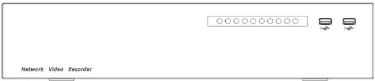
Table 2-3 Front panel function
| Port | Description |
| PWR | When the NVR is operating, the PWR indicator is steady on. When the NVR is shut down, the PWR indicator is turned off. |
| HDD | Hard disk status indicatorThis indicator flashes when data is transmitted. |
 | Only connected to an USB mouse |
Figure 2-4 WiFi model

Table 2-4 Front panel function
| Port | Description |
| PWR | When the NVR is operating, the PWR indicator is steady on. When the NVR is shut down, the PWR indicator is turned off. |
| NET | Network status indicatorThis indicator flashes when data is transmitted. |
| REC | Hard disk status indicatorThis indicator flashes when data is transmitted. |
| Only supports connected to an USB mouse |
2.2 Back Panel
Figure 2-5 3704E1-P4

Figure 2-6 3804-E1-P4/3504E1-P4/3604E1-P4

Figure 2-7 3808E1-P8E/3508E1-P8

Table 2-5 Real panel function
| Port | Description |
| POE | POE network interfaces |
| LAN | RJ 45 10/100/1000 Mbps adaptive Ethernet interface |
| AUDIO OUT / AUDIO IN | Audio output / Audio input |
| VGA | Video output interface |
| HDMI | |
| Alarm I/O | Alarm input/Alarm output |
| GND | |
| DC48V | Connected to an external power adapter |
Figure 2-8 3632E4-P16

Figure 2-9 3816E2-P16/3516E2-P16/3532E2-P16

Table 2-6 Real panel function
| Port | Description |
| POE | POE network interfaces |
| LAN | RJ 45 10/100/1000 Mbps adaptive Ethernet interface |
| AUDIO OUT / AUDIO IN | Audio output / Audio input |
| VGA | Video output interface |
| HDMI | |
| USB 3.0 | Only connected to 3.0 U disk |
| Alarm I/O | Alarm input/Alarm output |
| GND | |
| DC48V | Connected to an external power adapter |
Figure 2-10 3632E4/3664/E4

Figure 2-11 3632E8/3664E8

Table 2-7 Real panel function
| Port | Description |
 | Alarm input and alarm output./RS485 |
| LINE OUT / LINE IN | Audio output / Audio input |
| LAN1 /LAN2 | RJ 45 10/100/1000 Mbps adaptive Ethernet interface. .LAN1 is deployed default gateway and used for external network. LAN2 is used for internal network. |
| VGA | Video output interface |
| HDMI (1/2) | |
| RS232 | Standard RS232 serial communication interface of the device |
| USB 3.0 | Only connected to 3.0 U disk |
| E SATA | External hard disk interface |
 | Power switch |
 | Safe ground screw of the device |
 | AC 110V/220V power input interface |
Figure 2-12 2516E2/3816E2

Figure 2-13 2504E1/2508E1/3804E1/3808E1

Table 2-8 Real panel function
| Port | Description |
 | Alarm input and alarm output./RS485 |
| LINE OUT / LINE IN | Audio output / Audio input |
| LAN | RJ 45 10/100/1000 Mbps adaptive Ethernet interface |
| VGA | Video output interface |
| HDMI | |
| RS232 | Standard RS232 serial communication interface of the device |
| USB 3.0 | Only connected to 3.0 U disk |
| E SATA | External hard disk interface |
 | Power switch |
 | Safe ground screw of the device |
 | Connected to an external power adapter |
Figure 2-14 WiFi model
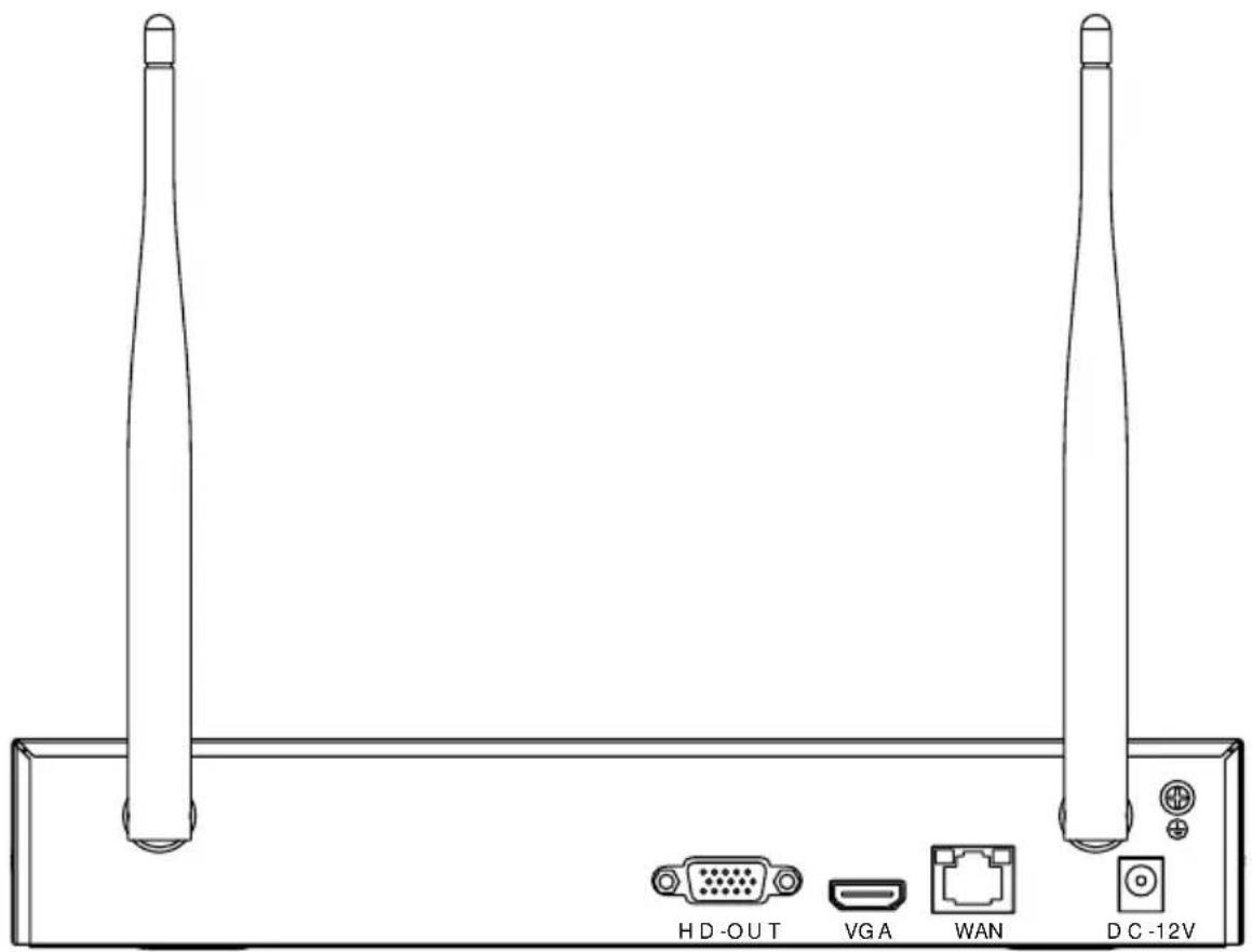
Table 2-9 Real panel function
| Port | Description |
| WAN | RJ 45 10/100/1000 Mbps adaptive Ethernet interface |
| VGA | Video output interface |
| DC 12V | Connected to an external power adapter |
| Safe ground screw of the device |
![graph TD A["Device Port"] -->|Audio out| B["Monitor"] A -->|Audio in| C["Router/Switch"] A -->|Audio in| D["Screen"] A -->|Audio in| E["Alarm"] A -->|IP cameras| F["IP Camera"] A -->|Power| G["Power"] A --> H["Network user"] A --> I["Network user"] A --> J["Network user"]](/content/2026/05/1015136/images/a10ec42cff744e5d2bc8616a8cd85aa462b3b7738610c10cb347653fcc0c0034.jpg)
![graph TD A["Port 1"] --> B["IOE PORTS"] B --> C["Audio out"] B --> D["Audio in"] B --> E["Router/switch"] F["Port 2"] --> G["USB3.0 disk"] H["Port 3"] --> I["ALARM ID"] J["Port 4"] --> K["Screen"] L["Port 5"] --> M["USB3.0 disk"] N["Port 6"] --> O["ALARM out/in"] P["Port 7"] --> Q["Screen"] R["Port…](/content/2026/05/1015136/images/3b0e9f36583eae82edc49c739229de95c0e8eba6be918732464506d5b9aa796c.jpg)
![graph TD A["Server"] -->|USB3.0 disk| B["USB3.0 disk"] A -->|e-SATA hard disk| C["e-SATA hard disk"] A -->|Audio in/out| D["Alarm in/out"] A -->|Audio out| E["Audio in"] A --> F["RS232 interface"] F --> G["Screen"] F --> H["Router/switch"] H --> I["Network user"] H --> J["Network user"] H --> K["Net…](/content/2026/05/1015136/images/c1add4b7679b34cef55cd04017d2d3c8e793622982f60483b1393ece2fd1b4e0.jpg)
2.3 Important Notes
Thank you for choosing the NVR. Please read the user manual carefully before using this product.
The NVR is a complex system-based device. To avoid misoperations and malfunctions caused by environmental factors and human factors during installation, commission, and application, note the following points when installing and using this product:
Read the user manual carefully before installing and using this product.
- Use Monitoring dedicated hard disks as the storage devices of the NVR with high stability and competitive price/performance ratios (the quality of hard disks sold on markets varies greatly with different brands and models).
- Do not open the enclosure of this product unless performed by a professional person to avoid damage and electric shock.
• We are not liable for any video data loss caused by improper installation, configuration, operation, and hard disk errors. - All images in the document are for reference only, please subject to the actual products.
2.4 About This User Manual
Please note the following points before using this user manual:
• This user manual is intended for persons who operate and use the NVR.
- The information in this user manual applies to the full series NVR, NVR as an example for description.
- Read this user manual carefully before using the NVR and follow the methods described in this manual when using the NVR.
• If you have any doubts when using the NVR, contact your product seller.
- As our products are subject to continuous improvement, we reserve the right to modify product manual, without notice and without incurring any obligation.
2.5 Installation Environment and Precautions
Installation environment
Table 2-10 defines the installation environment of the NVR.
Table 2-10 Installation environment
| Item | Description |
| Electromagnetism | The NVR conforms to national standards of electromagnetic radiation and does not cause harm to the human body. |
| Temperature | -10°C to +45°C |
| Humidity | 20% to 80% |
| Atmospheric pressure | 86 Kpa to 106 Kpa |
| Power supply | DC 12V, DC 48V 2A(1 HDD) or AC110/ 220V 4A(2 HDDs or more), please refer to actual products. |
| Power consumption | <15W (not including the hard disk) |
Installation precautions
Note the following points when installing and operating the NVR:
- The power adapter of the NVR uses DC48V±20% input. Do not use the NVR when voltage is too high or too low.
• Install the NVR horizontally. - Avoid direct sunlight on the NVR and keep away from any heat sources and hot environments.
- Connect the NVR to other devices correctly during installation.
- The NVR is not configured with any hard disk upon delivery. Install one or more hard disks when using the NVR for the first time.
The NVR identifies hard disk capacity automatically and supports mainstream hard disk models.
You'd better use high-quality hard disk so that the NVR can work stably and reliably. Please refer to chapter 10 Disk Compatibility
Other precautions
- Clean the NVR with a piece of soft and dry cloth. Do not use chemical solvents.
• Do not place objects on the NVR.
The NVR meets the national standards of electromagnetic radiation and does not cause electromagnetic radiation to the human body.
Series of NVR
3 Install device
3.1 Process
![graph TD A["Start"] --> B["Unpacking inspection"] B --> C["Install hard disk"] C --> D["Connect cable"] D --> E["Boot device"] E --> F["Configure and enter interface"] F --> G["End"]](/content/2026/05/1015136/images/dac052cbbf222b8e81cbb0b3d2f0b2b5b7ab84cbb97eae2b7d1cca46b41506b6.jpg)
Step 1 Check the appearance, packaging, and label of the device to make sure there is no damage.
Step 2 Install the hard disk and fix it to the device bracket.
Step 3 Connect the device cable.
Step 4 Make sure the device is properly connected. Power up and turn on the device.
Step 5 Configure the initial parameters of the device. The boot wizard contains network configuration, add cameras, and manage disks. For details, please refer to the chapter of Wizard.
3.2 Unpacking Inspection
When you receive the video recorder, please check it against the following table.
Should you have any issues, please don't hesitate to contact our after-sales support.
Table 3-1 Unpacking inspection
| No | Item | Check content | |
| 1 | Overall packaging | Appearance | Is there any obvious damage |
| Package | Is there accidental impact | ||
| Accessories | Is it complete | ||
| 2 | Label | Label of device | Is the equipment model consistent with the order contract?Whether the label is torn NOTEDo not tear or discard, otherwise warranty service is not guaranteed. When you call the company for sales personnel calls, you need to provide the serial number of the product on the label. NOTEDo not tear or discard, otherwise warranty service is not guaranteed. When you call the company for sales personnel calls, you need to provide the serial number of the product on the label. |
| 3 | Cabinet | Package | Is there any obvious damage |
| Data cable, power cable, fan power supply, and motherboard | Is the connection loose? NOTEIf it is loose, please contact the company's after-sales personnel. NOTEIf it is loose, please contact the company's after-sales personnel. | ||
NOTE
NOTE
3.3 Install Hard Disk
Check if the hard disk is installed during the first installation. Please use the recommended hard disk model. For more details, see 10 Disk Compatibility.
It is not recommended to use a PC dedicated hard disk.

CAUTION
When replacing the hard disk, please turn off the power and then open the device to replace the hard disk.
Please use the monitoring dedicated SATA hard disk recommended by the hard disk manufacturer.
Choose the hard disk capacity according to the recording requirements.
3.3.1 Install One or Two Hard disks
Step 1 Remove the screws for fixing the upper cover and take down the cover.
Step 2 Take out the screws and silicone cushion, pass the screws through the silicone cushion, and secure it to the screw holes, as show in Figure 3-1..
Figure 3-1 Installing the hard disk screws

Step 3 Pass the screws through the holes on the base and put the hard disk in place, as shown in Figure 3-2.
Figure 3-2 Install hard disk

Step 4 Turn the device over, and fasten the fixing the rest 2 screws, as shown in Figure 3-3.
Figure 3-3 Install hard disk

Step 5 Insert the hard disk data cable and power cable, then put back the upper cover and fasten the fixing screws.
3.3.2 Install Four Hard disks
Step 1 Remove the top cover by loosening the screws..
Step 2 Put the hard disk under the hard disk bracket, hold the hard disk with one hand and aim the hard disk hole at the bracket hole, and then tighten the screws to fix (first install the hard disk near the fan), as shown in Figure 3-4.
Figure 3-4 Installing the hard disks

Step 3 Install other hard disks following step 2.
Step 4 Insert the hard disk data cable and power cable, and then put back the upper cover and tighten the fixing screws.
3.3.3 Install Eight Hard disks
Step 1 Remove the screws for fixing the upper cover and take down the cover.
Step 2 Loosen screws on both sides to lift the upper bracket as shown figure.
Figure 3-5 Loose screws lift the upper bracket

Step 3 Put the hard disk under the lower bracket, hold the hard disk with one hand and aim the hard disk hole at the bracket hole, then fix the screws for hard disk, as shown in Figure 3-6.
Step 4 Pull down the upper bracket and secure it by tightening the screws, then install other hard disks in upper layer following step 3, as shown in the right figure in Figure 3-6.
Figure 3-6 Unscrew the screws
lift the upper bracket

Step 5 Insert the hard disk data cable and power cable, then put back the upper cover and fasten the fixing screws.
4 Basic Operations
4.1 Power on the Device

CAUTION
- Ensure that the NVR is correctly connected to a power supply, and a display is correctly connected to the high-definition multimedia interface (HDMI) or video graphics array (VGA) port of the NVR before power-on.
- In some environments, abnormal power supply may cause the failure of the NVR to work properly and even damage the NVR in severe cases. It is recommended to use a regulated power supply to power up the NVR in such environments.
After connecting the NVR to a power supply, the power indicator is always on. Start the NVR.
The real-time video screen is displayed as shown in Figure 4-1.
Figure 4-1 Real-time video screen
![NVR Activation Language English Username adults Enter a new password Password Confirm the new password Password Enter channel default password Password - Valid password range [0 - 32] characters. - At least 2 kinds of numbers/overcase/uppercase or special. - Only these special characters are support…](/content/2026/05/1015136/images/45b5db3db51725b48105f022d161d317ad2dce4179a9068644671cc017f261a3.jpg)

NOTE
Users need to provide a hard disk for the NVR. The hard disk is strictly detected during device startup.
If the detection result failed, the possible causes are as follows.
The hard disk is new and is not formatted. Login to the system and format the hard disk.
The hard disk is formatted, but the file system is inconsistent with the file system supported by the
NVR. Format the hard disk.
The hard disk is damaged.
4.2 Activation
When users login the device at first time, or reset the NVR, you need to activate the device and set login and channel default password, as shown in Figure 4-2.
Figure 4-2 Activation
![Activation Language English Username admin Enter a new password Password Confirm the new password Password Enter channel default password Password - Valid password range [6–32] characters. - At least 2 kinds of numbers,lowercase,uppercase or special . - Only these special characters are supported l@…](/content/2026/05/1015136/images/f451c3ad3f40741bd9addc4f3f4f3ca82322d9e4e457dce8529f1f5ca5ef2933.jpg)
Table 4-1 Description of activation
| Name | Description |
| Username | The default username is admin, and “admin” is super administrator. |
| Password | Valid password range 6-32 characters.At least 2 kinds of numbers, lower case, upper case or special characters contained.Only these special characters are supported! @#&*+=-%&”(),/’..;;<>?^|~[]{} Channel default password limit is not empty. |
| Confirm password |
Basic Operations User Manual
| Channel password | The NVR channel connection password is the camera login password. |
Users can set the pattern unlock to login the device, as shown in Figure 4-3.
Figure 4-3 Set pattern unlock


NOTE
After setting pattern unlock, the system default login will be pattern unlock login. If pattern unlock is not set, you need enter the password to log in.
If you don't need to set the pattern to unlock, click "Skip this step".
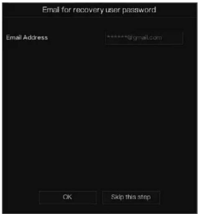
Allow the Mailbox to receive verification code. The password will be reset when you forget it, as shown in Figure 4-4.
Figure 4-4 Set Email

NOTE
Set the email address, if you forget the password, you can though the email address to receive the verification, and reset the password.
If the email address is not set, you can reply to the secure question or send the QR code to the seller to get the temporary password to login to the device.
If you don't need to set the email, click "Skip this step".
Set the secure questions to create a new password in case the user forgets the password.
Figure 4-5 Set question


NOTE
The user can set three questions, and if they forget the password, they can answer the question and enter the reset password interface.
Questions one can be set: Your favorite animal
Company name of your first job
The name of the first boy/girl you like
The worst security question you have ever seen
The most funny worst design you have ever seen
Your favorite team
Your favorite city
The three question options cannot be set to the same issue.
The answer requires a minimum of four characters and a maximum of 32 characters.
If you do not want to set a password question, you can click Skip this step.
4.3 Power off the Device
Click the main menu and choose System > Maintenance, the maintenance setting page is displaying, click Shutdown to power off the NVR. If there is a power switch on the rear panel of the NVR, you can power off the power switch to disconnect the NVR from the power supply.
4.4 Login to the System
Step 1 Login to the device (two modes to login). The pattern unlock is as shown in Figure 4-6.
Figure 4-6 Pattern unlock login page
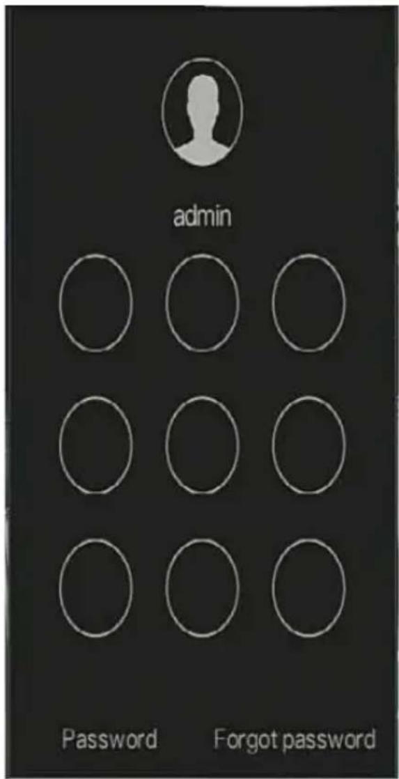
Step 2 On the NVR login page, click “Password” to enter pattern unlock interface. If users don’t set the pattern unlock it will show password to login interface directly, select the language, as shown in Figure 4-7.
Figure 4-7 Password login page

Step 3 Input the username and password.

NOTE
The password incorrect more than 3 times, please login again after 5 minutes. You can also power off, and power on to start on the device, input the correct password to avoid waiting five minutes. If user forget password, click Forgot password. User can choose a way to create new password:
- Scan the QR code and send the QR code to your seller, se the seller will send you the verification code to create a new password.
- Answer the secure question to create new password.
Step 4 Click Login to access the main User Interface (UI).Modify the default password, as shown in Figure 4-8
Figure 4-8 Modify default password
![Modify default password New password Confirm password Modify password - Valid password range [6-32] characters. - At least 2 kinds of numbers,lowercase,uppercase or special character contained. - Only special characters are supported!@#$*+=-_](/content/2026/05/1015136/images/afa89b8a0f425992a6a2798633236d61ed9c5eff1199cf95d17b1301f78b4041.jpg)
----End
5 Wizard
Login the NVR, the wizard is showing on live video, click Start Wizard, the pop-up window will show as Figure 5-1.
Figure 5-1 Wizard
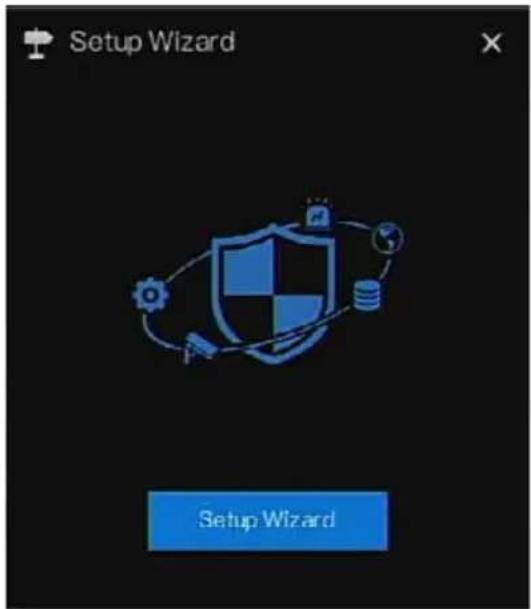
Figure 5-2 Wizard of network

Step 1 Contains he parameter, the details please refer to Table 5-1.
Table 5-1 Network parameter
| Parameter | Description | Configuration |
| DHCP | Enable DHCP, the device will obtain the IP address from the DHCP server. | [Setting method] Enable |
| IP Address | Set the IP of device when DHCP is disable | [Setting method] Manual |
| Subnet mask | Set the subnet mask of device | [Setting method] Manual [Default value] 255.255.255.0 |
| Gateway | If the user wants to access device, he must set that | [Setting method] Manual [Default value] 192.168.0.1 |
| Obtain DNS | N/A | [Setting method] |
Wizard User Manual
| Parameter | Description | Configuration |
| automatically | Enable | |
| Preferred DNS Server | N/A | [Setting method]Manual[Default value]192.168.0.1 |
| Alternate DNS Server | N/A | [Setting method]Manual[Default value]8.8.8.8 |
| Enable Port Mapping | Enable to set the ports of HTTP, HTTPS, RSTP, Control.Auto: device to obtain Web port, data port and client port.Manual: user set the port manually. | [Setting method]Choose type from drop-down list[Default value]Auto |
| HTTP Port | N/A | [Setting method]When Port Mapping is manual, you need to set these. |
| HTTPS Port | N/A | |
| RTSP Port | N/A | |
| Control Port | N/A |
Step 2 Click Next to view the basic information about device, as shown in Figure 5-3.
Figure 5-3 Wizard of date and time

Choose date format and time format from drop-down list.
Click to synchrony time from network.
Disable the NTP-Sync, set time manually.
Roll the mouse to choose year, month and day when clicking the date.
Roll the mouse to choose hour, minute and second when clicking the date.
Click Modify Time to save the time.
Step 3 Click Time Zone, choose the current time zone from drop-down list, as shown in Figure 5-4.
Figure 5-4 Wizard of time zone
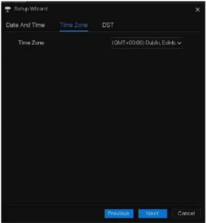
Step 4 Click DST, enable the DST, set start and end time. Select offset time from drop-down list. Step 5 Click Next to enter the adding camera wizard, as shown in Figure 5-5.
Figure 5-5 Wizard of adding camera

The details of adding camera please refer to chapter 7.1.
Step 6 Click to enter wizard of disk, as shown in Figure 5-6.
Figure 5-6 Wizard of disk

You can view the general information of disk. You can also format the disk.
Step 7 Click to enter wizard of P2P, as shown in Figure 5-7
Figure 5-7 P2P

Step 8 Enable the P2P, user can use mobile devices to manage the NVR by scanning the P2P ID, if the mobile phone has loaded the InView Pro 4(search the APP at App Store or Google Play).
Step 9 Click Next to enter the wizard of resolution, as shown in Figure 5-8. Choose resolution from drop-down list. (the highest resolution is 3840*2160)
Figure 5-8 Wizard of resolution
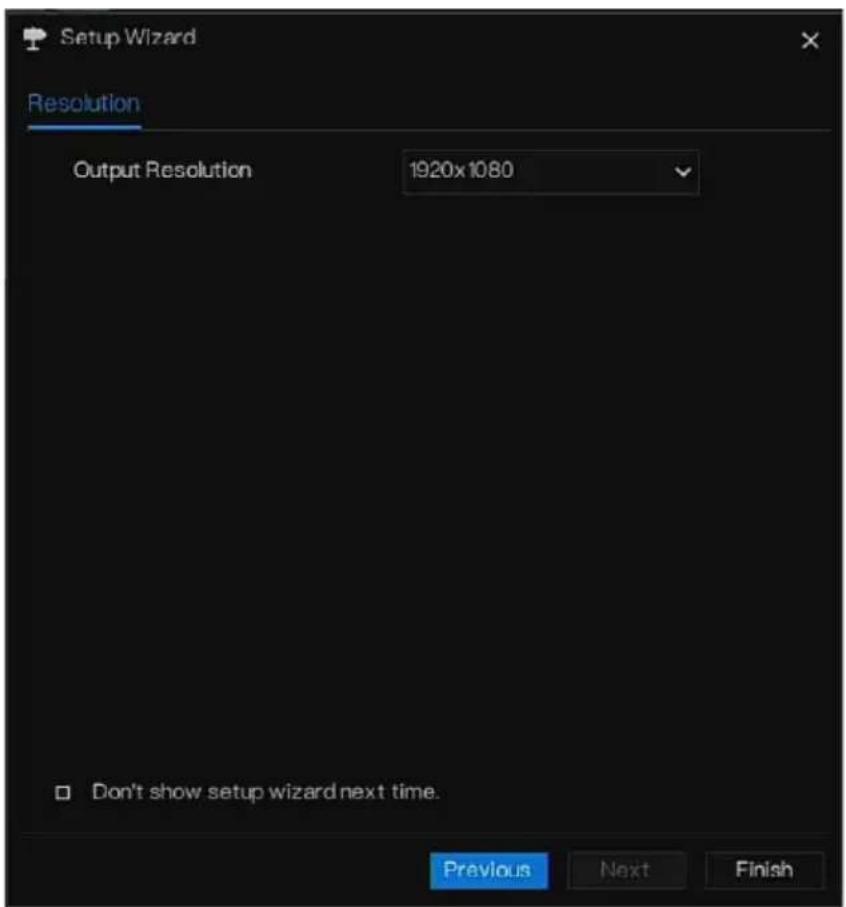
Step 10 Click Finish to end the wizard, tick the Don't show setup wizard next time, it would not show at next time. Reopen wizard at system > User > Advance setting.
6 Quick Navigation
6.1 Quick Bar
After the NVR operation screen is displaying, move the cursor to the far bottom of the NVR screen. The NVR floating menu bar is displaying.
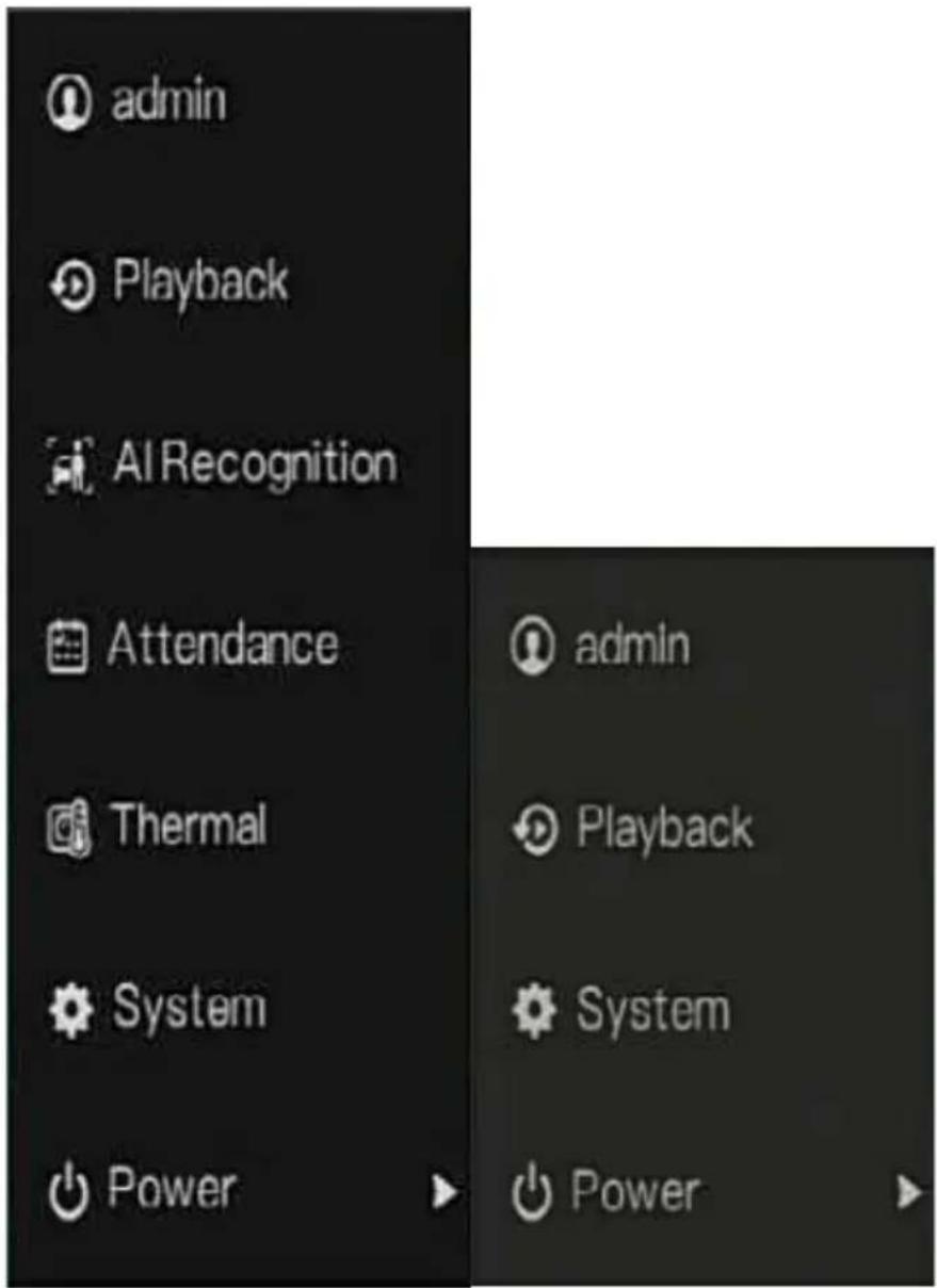
Click in the left of NVR floating menu bar. The quick home menu is showing. The quick home menu contains Playback, System and Power (Shutdown, Reboot and Logout) as shown in Figure 6-1.
Figure 6-1 Quick home menu
In the middle of NVR floating menu bar, the video tool bar provides video window switching, auto SEQ, volume, playback, and channel information, as shown in Figure 6-2.
Figure 6-2 Real-time video toolbar
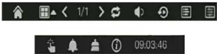
The real-time video toolbar is as follows:

: Layout. Users can choose layout and add new layout strategies as shown in
Figure 6-3. Click ▲ on the right of screen splitting format and choose the channels to view the video. Click + to add a new layout.
Figure 6-3 Add layout
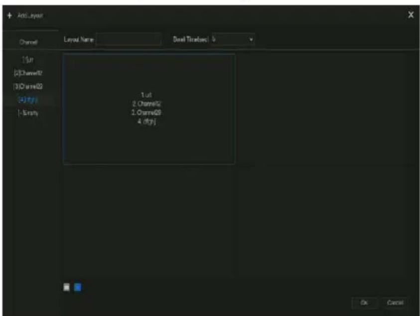
Input the layout name, choose the dwell time, choose the splitting format. Choose one channel or several channels to add on screen.

Auto SEQ. click icon, the layout dwell on screen is enabled, for how to set the dwell on,
please see chapter 7.5.5.

Audio. Click on the icon, the audio setting screen is displaying, where you can choose the
channel and adjust the volume.

: Channel information, tick the channel or encode, the live video will show the channel
information.
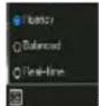
: Preview strategy, users can switch the real-time preview mode according to the network.
There are three modes: fluency, balanced and real-time.
A main menu quick toolbar is on the right of NVR floating menu bar. The main menu quick toolbar provides Manual alarm, Alarm information, Clean alarm, Information and time, as shown in Figure 6-4.
Figure 6-4 Main menu quick toolbar


: Manual alarm, click the icon, users can set different channels, choose alarm out, the window shows in Figure 6-5.
Figure 6-5 Manual alarm
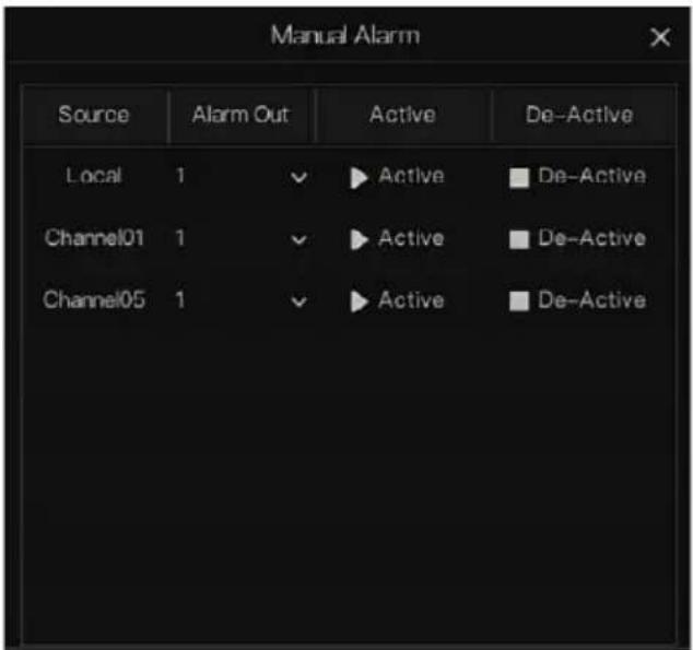

: Alarm message, click on the icon for more details as shown in Figure 6-6.
Figure 6-6 Alarm message


: Clean alarm, click icon and clean the current alarm actions like voice and external alarm out.

: Information, click icon and the general information would show, like network, system, channel, disk and alarm, as shown in Figure 6-7.
Figure 6-7 Information

6.2 Real Time Video Bar
Right click at realtime image, the quick setting will show as figure.

Record: click the icon and start to record video. Click again to end record.
Instant playback: click the icon, the window will be recording video five minutes ago.

is the time bar of playback.
Audio: open or close the audio.
PTZ: This function is only applied for speed dome cameras. The monitored camera can focus, zoom or iris at this pop-up window. You can adjust every parameter as shown in Figure 6-8.
Figure 6-8 PTZ adjust screen


: adjust direction of camera.

: At this part, perform Advanced, Scan and Tour settings.

: 3D, this function can only be used for high speed dome camera. Click the icon to enter the camera live video screen, use the mouse to move the camera or zoom in or out the lens. Click the point to zoom in. Drag and draw the area, zoom in the drawing area, Reverse drag to zoom out.

: Zoom in, click zoom in, roll the mouse wheel to zoom in and zoom out. Right-click to exit the zooming.

: Image, click the icon, as shown in Figure 6-9. Select scene, and drag cursor to adjust value of brightness, sharpness, contrast and saturation.
Figure 6-9 Camera picture parameter


: Two way audio. The NVR and camera can talk to each other.

: Snapshot panorama. If an USB storage device is connected to the NVR device, click to save the panorama snapshot directly.

: fisheye (only used for fisheye cameras), click to switch the fisheye modes, as shown in Figure 6-10.
Figure 6-10 Fisheye

6.3 Playback
Playback refers to playing back a video, fixed-point playback, playback the search type. Click 📷 is the quick navigation bar to access the playback screen, as shown in Figure 6-11.
Figure 6-11 Playback screen
![Playback Time Search Picture Grid Event Recording Backup List Select All [1] Channel01 [2] Channel02 [3] Channel03 [4] Channel04 [5] Channel05 [6] Channel06 [7] Channel07 [8] Channel08 2022 01 Schedule Record ManualRecord Alarm Record 11:47:08 Co 24/04/2022 11:47:08](/content/2026/05/1015136/images/28cd0fdd297fba3d70dc3f75ba47617b7a99c58cfc967c318d58350d3b434523.jpg)
Choose the channels from the channels list, click one day to play (the date has blue line, it means there is recording video at this day, it doesn't mean for all channels has video.)
It maybe has three color bars on the time bar, the blue one is schedule record, the yellow one is manual record, and the red one is alarm record.
The toolbar at the bottom of the playback screen is described as follows:


: Layout.

: Reversed, pause/play, stop.

:30s backward, 30s forward.

: Triple speed, it supports up to 32 times to playback. Click the Number to switch the
speed.

: Zoom. Roll the roller of mouse to zoom in or out.

: Audio.

: Start and end backup. Click the icon, the video backup starts, select the video and click the icon again.
The backup type appears. Click save. And saving the file pop ups as Figure 6-12. Click OK to save.
This function is available after an USB disk is plugging in the device.
Figure 6-12 Select directory


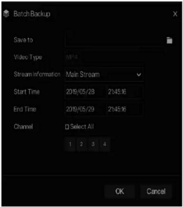
: Batch backup, click the icon to backup multi-channels, as shown in Figure 6-13.
Choose the folder to save, select the stream information from drop-down list, set the start time and end time, select the channels, Click OK to backup. The backup videos are marked by watermark, you can view it by our player.

: Snapshot panorama. Click to save it to USB storage device on NVR.
Figure 6-13 Batch backup

: Type of time bar, recording video can show
6.3.1 Time Search
Search refers to searching for a video by date and time.
Operation Description
Click in the quick navigation bar to access the search screen, as shown in Figure 6-14.
Figure 6-14 Time Search screen
![Playback Time Search Picture Grid Event Recording Backup List Select All [1] Channel01 [2] Channel02 [3] Channel03 [4] Channel04 [5] Channel05 [6] Channel06 [7] Channel07 [8] Channel08 2022-04-23 11:47:15 Sat SN-IPVSOSOUIAR-Z2.7-13.6-13 Schedule Record Manual/Record Alarm/Record 11:47:08 Go 03:20 04…](/content/2026/05/1015136/images/2485d28db2bb7dc3699e3fb41000cbad2512e52993fbf81887e1c0ae58336038.jpg)
Operation Steps
Step 1 Select a camera or cameras in the camera list on the left side of the search screen. The video view of the selected camera is displaying in the play window.
Step 2 Select a date in the calendar on the light-down side of the search screen.
Step 3 Choose record type, and search the video quickly.
Step 4 Choose proper button to adjust video.
----End
6.3.2 Picture Grid
Picture grid refers to evenly dividing the video of a channel by time range and searching for a video based on thumbnails divided by time range.
Click Picture Grid navigation bar to access the picture grid screen, as shown in
Figure 6-15.
Figure 6-15 Picture grid screen
![Playback Time Search Picture Grid Event Recording Backup List [1] Channel01 [2] Channel02 [3] Channel03 [4] Channel04 [5] Channel05 [6] Channel06 [7] Channel07 [8] Channel08 00:00:00 02:00:00 04:00:00 06:00:00 08:00:00 10:00:00 12:00:00 14:00:00 16:00:00 18:00:00 20:00:00 22:00:00 23/04/2022 03:00:0…](/content/2026/05/1015136/images/43c574d71d9e8bfbab1f8dccaca1d5249df8a802b544b605245150fc987e451e.jpg)
Operation Steps
Step 1 Select a camera in the camera list on the left side of the picture grid screen. Videos shot by the camera in the earliest time range on the current day are displayed as thumbnails in the window on the right side.
Step 2 Select a date from calendar.
Step 3 A day are dividend to 12 grids, every two hours is a grid. Click the image to change the interval.
Step 4 Select a required thumbnail, double-click it or right-click it and choose Play from the shortcut menu to play the video.
Step 5 Click to replay the gird individually.
Figure 6-16 Replay

----End
6.3.3 Event Recording
Click the quick navigation bar; choose Event at title to access the alarm event screen, as shown in Figure 6-17
Figure 6-17 Event screen

Operation Steps
Step 1 Select cameras in the camera list on the left.
Step 2 Set start and end time.
Step 3 Tick the alarm type, such as alarm in, camera alarm in, motion alarm, video loss, intelligent analysis and abnormal alarm
Step 4 Click Search by the event, the result would show at window.
Step 5 Double click to play video about event. It will play recording video.

play the recording video.

backup the recording video.

the type of intelligent analysis and abnormal alarm are subdivided, users can tick Detail Alarm to show.
Intelligent analysis includes perimeter, single virtual fence, double virtual fences, loiter, multi loiter, object left, object removed, abnormal speed, converse, illegal parking, signal bad, register, stranger, registered license plate, over temperature, low temperature, abnormal temperature, threshold warning, threshold alarm, temperature difference warning, temperature difference alarm, temperature section alarm, face temperature, wear mask, no mask, personnel count threshold alarm, personnel count threshold alarm(IPC).
Abnormal alarm includes disk error, IP conflict, network disconnected.
User can choose the accurate alarm events to search.
----End
6.3.4 Backup List
Click on the quick navigation bar, choose at title to access the backup screen, as shown in Figure 6-18.
Figure 6-18 Backup screen

View detailed information of backup. Click on Delete to quit the download.
----End
6.4 AI Recognition (Only for Some Models)
At AI recognition interface, we can set the Real time Comparison, Smart search, Archives library, Comparison configuration.
The all snapshots is able to be added to the libraries according the real needs
6.4.1 Real Time Comparison
Real time comparison can compare human faces, vehicle license plate, and AI(include riding, vehicle, full body)
6.4.1.1 Human Face
At real time comparison interface, click the enter the human face comparison interface, choose the cameras with face recognition function to play live video, the snapshots of camera will be compared with the templates which have been registered in libraries, the result shows as in Figure 6-19.
Figure 6-19 Human face comparison
![AI Recognition Real-time comparison Smart Search Archives Library Comparison Configuration 2019-11-05 16:39 30 Tues Select All [1] Channel01 [2] Channel02 [3] Channel03 [4] Channel04 [5] Channel05 [6] Channel06 [7] Channel07 [8] Channel08 [9] Channel09 [10] Channel10 [11] Channel11 [12] Channel12 [1…](/content/2026/05/1015136/images/79ec18258c5b2d1e339b679c8ec31fc87a4434b8b0c16789165a1a6a5d93c173.jpg)
Click the “+” to add the snapshot to face library immediately.
Snapshot in real time video, put the cursor on picture such as +, but add it to face
library, or face search. The cursor on area and the pictures are not update, move the mouse so that the pictures can be shown in time.
----End
6.4.1.2 Vehicle License Plate
At real time comparison interface, click the to enter the vehicle license plate comparison interface, choose the cameras with license plate recognition function to play live video, the snapshot of camera will be compared with libraries, the result shows as in Figure 6-20.
Figure 6-20 Vehicle license plate

Click the “+” to add the snapshot to license plate library immediately.
----End
6.4.1.3 Vehicle and Full Body
At real time comparison interface, click the ☐ to enter the vehicle license plate comparison interface, choose the AI recognition cameras to play live video, the snapshot of camera will be compared in libraries, the snapshot to vehicle and full body will show at the bottom of page, the result shows as in Figure 6-21.
Figure 6-21 Full body
![AI Recognition Real-time comparison Smart Search Archives Library Comparison Configuration Select All 2019-01-16 16:21:21 Wind [1] Channel01 [2] Channel02 [3] Channel03 [4] Channel04 [5] Channel05 [6] Channel06 [7] Channel07 [8] Channel08 [9] Channel09 [10] Channel10 [11] Channel11 [12] Channel12 [1…](/content/2026/05/1015136/images/1433b5191d277ebe858bddf384da4ef1c4fb68151278ee8fe714428d8ac5032a.jpg)
----End
6.4.1.4 Real-time Body Temperature Filter
At AI recognition, click to enter the real-time body temperature filter, Users can select the body temperature camera, which will display temperature recordings and over-temperature snapshots. Click full-screen, the channel list and snapshots statistics will be hidden.
Figure 6-22 Real-time body temperature filter
![AI Recognition Real-time comparison Smart Search Archives Library Comparison Configuration Snapshots Today 1981 142 Total Snapshots Over Temperature Device List Select All [1] Channel01 [2] Channel02 [3] Channel03 [4] Channel04 [5] Channel05 [6] Channel06 [7] Channel07 [8] Channel08 [9] Channel09 [1…](/content/2026/05/1015136/images/ae3e4821d169dc551f9b5b2d0e63b34e1f110668a919b442742c80a7a6fb10d5.jpg)
Figure 6-23 Full screen

If users enable the mask detection, the snapshot results will reminder wear mask or no mask.
----End
6.4.2 Smart Search
At smart search interface, user can search the human face, vehicle license plate, full body, car, body temperature.
Up to 1000 pictures can be displayed. Click to see more details and export search result.
6.4.2.1 Human Face Search
Figure 6-24 Human face search
![AI Recognition Real-time comparison Smart Search Archives Library Comparison Configuration Select All [1] Channel01 [2] Channel02 [3] Channel03 [4] Channel04 Start Time 27/04/2020 14:08:44 End Time 27/04/2020 14:39:44 By Picture By Feature Picture Reset Search Time 27/04/2020 14:08:52 Channel Channe…](/content/2026/05/1015136/images/bdd515a40bf6b8d9df3e4c03b067195345f130d652e1129ae2212f447791d39b.jpg)
Step 1 Choose human face search at smart search interface.
Step 2 Tick the face recognition camera channels, set the start and end time.
Step 3 Choose the condition (by picture or by feature), the picture can be selected from the file folder.
Step 4 Click "Search" to search the snapshot of human face.
Step 5 The result will show at the middle of page, click the picture and the detail information show at the top right of page.
Step 6 The pictures can be added to library or used to search.
Step 7 Click play button of video to play the recording of snapshot, click “Backup” to back up the recording videos.
Figure 6-25 Back up
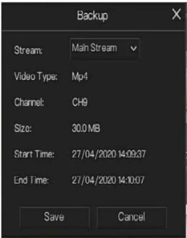
Step 8 Click "Export" to export the result, choose export type pictures or videos.
Figure 6-26 Export

Play video of snapshot, it will play a 30-seconds video before and after the snapshot.
Snapshot in real time video, put the cursor on picture such as my phone add it to face
library, or face search. The cursor on area 6 and the pictures is not update, move the mouse so that the pictures can be shown in time.
---End
6.4.2.2 Vehicle License Plate Search
Figure 6-27 Vehicle License Plate search

Step 1 Choose vehicle License Plate at smart search interface.
Step 2 Tick the vehicle license plate recognition camera channels, set the start time and end time.
Step 3 Input the license plate optionally.
Step 4 Click "Search" to search the snapshot of license plate.
Step 5 The result will show at the page, click "+" add to library.
Step 6 Click "Playback" to view the recording video, click "Backup" to back up the video.
Step 7 Click "Export" to export the result.
----End
6.4.2.3 Full Body Search
Figure 6-28 Full body search
![AI Recognition Real-time comparison Smart Search Archives Library Comparison Configuration Select All [1] Channel01 [2] Channel02 [3] Channel03 [4] Channel04 [5] Channel05 [6] Channel06 [7] Channel07 [8] Channel08 [9] Channel09 Start Time 27/04/2020 14:16:06 End Time 27/04/2020 14:16:06 Gender All C…](/content/2026/05/1015136/images/24c6722ca9445ad797fd4cdc21b5c9f787096c2df003d31d2d6567b76afe370d.jpg)
Step 1 Choose full body search at smart search interface.
Step 2 Tick the AI recognition camera channels, set the start time and end time.
Step 3 Set the gender, click cycling or no cycling.
Step 4 Click "Search" to search the snapshot of human face.
Step 5 The result will show at the middle of page, click the picture and the detail information show at the top right of page.
Step 6 Click play button of video to play the recording of snapshot, click “backup” to back up the video.
Step 7 Click "Export" to export the result.
----End
6.4.2.4 Vehicle Search
Figure 6-29 Vehicle search
![AI Recognition Real-time comparison Smart Search Archives Library Comparison Configuration Select All [1] Channel01 [2] Channel02 [3] Channel03 [4] Channel04 [5] Channel05 [6] Channel06 [7] Channel07 Start Time 12/03/2020 18:15:51 End Time 32/03/2020 18:40:51 Car color White Black Red Grey Other Res…](/content/2026/05/1015136/images/c69b3aa201fa1b7910c72b35d90e5ce7c074f73fb875bc0df1feb4e7e89488f9.jpg)
Step 1 Choose vehicle search at smart search interface.
Step 2 Tick the AI recognition camera channels, set the start time and end time.
Step 3 Tick the color.
Step 4 Click "Search" to search the snapshot of human face.
Step 5 The result will be showed at the middle of page, click the picture and the detail information show at the top right of page.
Step 6 Click play button of video to play the recording of snapshot, click “backup” to back up the video
Step 7 Click "Export" to export the result.
----End
6.4.2.5 Body Temperature Search
Figure 6-30 Body temperature search

Step 1 Choose body temperature search at smart search interface.
Step 2 Tick the AI recognition camera channels, set the start time and end time.
Step 3 Choose the person type, temperature type, input ID optionally.
Step 4 Click "Search" to search the temperature.
Step 5 Click "Export" to export the result
----End
6.4.2.6 Personnel Count
Figure 6-31 Personnel count

Step 1 Choose personnel count at smart search interface.
Step 2 Tick the AI recognition camera channels, set statistical type and date.
Step 3 Click "Search" to search the snapshot of human face.
Step 4 Click the data in different data tables .
----End
6.4.3 Archives Library
At archives library, users can add or edit the face library , license plate library.The license plate libraries can be imported to and exported from IP cameras.
6.4.3.1 Face Library
Figure 6-32 Face library

Click “+” to add a new face library.
Click "Add" to add person face.
Tick the person, click "Delete" to delete the person.
Click "Import" to add the person batch.
Click "Export" to export the all person in library.
Click "Filter" to filter the all persons in library, as shown in Figure 6-33.
Figure 6-33 Filter

Click operate icon to edit or delete the chosen person.
----End
6.4.3.2 License Plate Library
At license plate library interface, users can add/delete/operate the library. It supports the white-list and black-list according the libraries to export and import the library to IP cameras.
Figure 6-34 License plate library
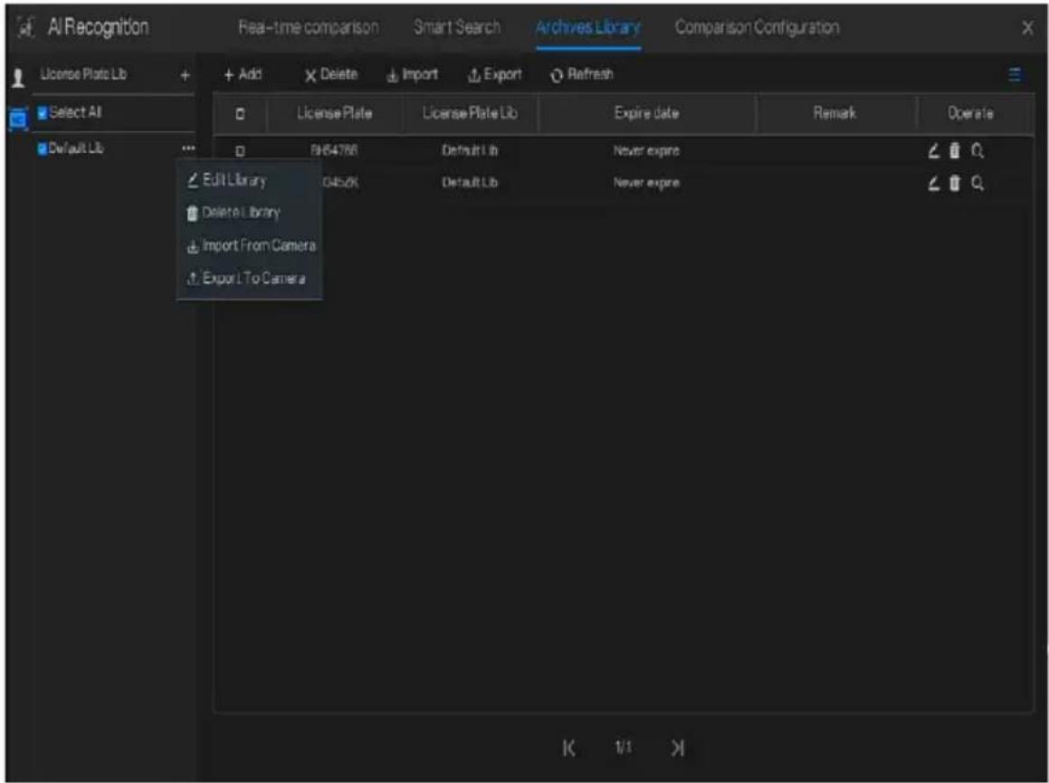
Click “+” to add a new license plate library.
Click "Add" to add a plate to library.
Tick the plate, click "Delete" to delete the license plate.
Click "Import" to add the license plate batch.
Click "Export" to export the all-license plate library.
Click operate icon to edit or delete the chosen license plate.
Click "Import from Camera" to select license plate library to channel.

Click "Export to Camera" to add license plate number to camera.

----End
6.4.4 Comparison Configuration

NOTE
The comparison function is only for AI cameras, please refer to actual cameras.
At comparison configuration interface, user can set the comparison of human face/ license plate/temperature/ mask detection configuration/ personnel count configuration.
6.4.4.1 Face Comparison
At face comparison interface, users can set different channels' strategy, such as similarity, display comparison result, face library, enable alarming, event action, arming time, as shown in Figure 6-35.
Figure 6-35 Face comparison
| Channel | Register Detect Library | Strainer Detect Library | Similarity | Operate |
| Channel1 | Default Lib | Default Lib | 80% | ✓ |
| Channel2 | Default Lib | Default Lib | 80% | ✓ |
| Channel3 | Default Lib | Default Lib | 80% | ✓ |
| Channel4 | Default Lib | Default Lib | 80% | ✓ |
| Channel5 | Default Lib | Default Lib | 80% | ✓ |
| Channel6 | Default Lib | Default Lib | 80% | ✓ |
| Channel7 | Default Lib | Default Lib | 80% | ✓ |
| Channel8 | Default Lib | Default Lib | 80% | ✓ |
| Channel9 | Default Lib | Default Lib | 80% | ✓ |
| Channel10 | Default Lib | Default Lib | 80% | ✓ |
| Channel11 | Default Lib | Default Lib | 80% | ✓ |
| Channel12 | Default Lib | Default Lib | 80% | ✓ |
| Channel13 | Default Lib | Default Lib | 80% | ✓ |
| Channel14 | Default Lib | Default Lib | 80% | ✓ |
| Channel15 | Default Lib | Default Lib | 80% | ✓ |
| Channel16 | Default Lib | Default Lib | 80% | ✓ |
| Channel17 | Default Lib |
Figure 6-36 Strategy

----End
6.4.4.2 License Comparison
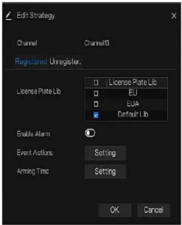
At license plate interface, users can set strategies of different channels of license plate recognition cameras, such as register and unregister, enable alarming, event action, arming time, as shown in Figure 6-37.
Figure 6-37 License comparison
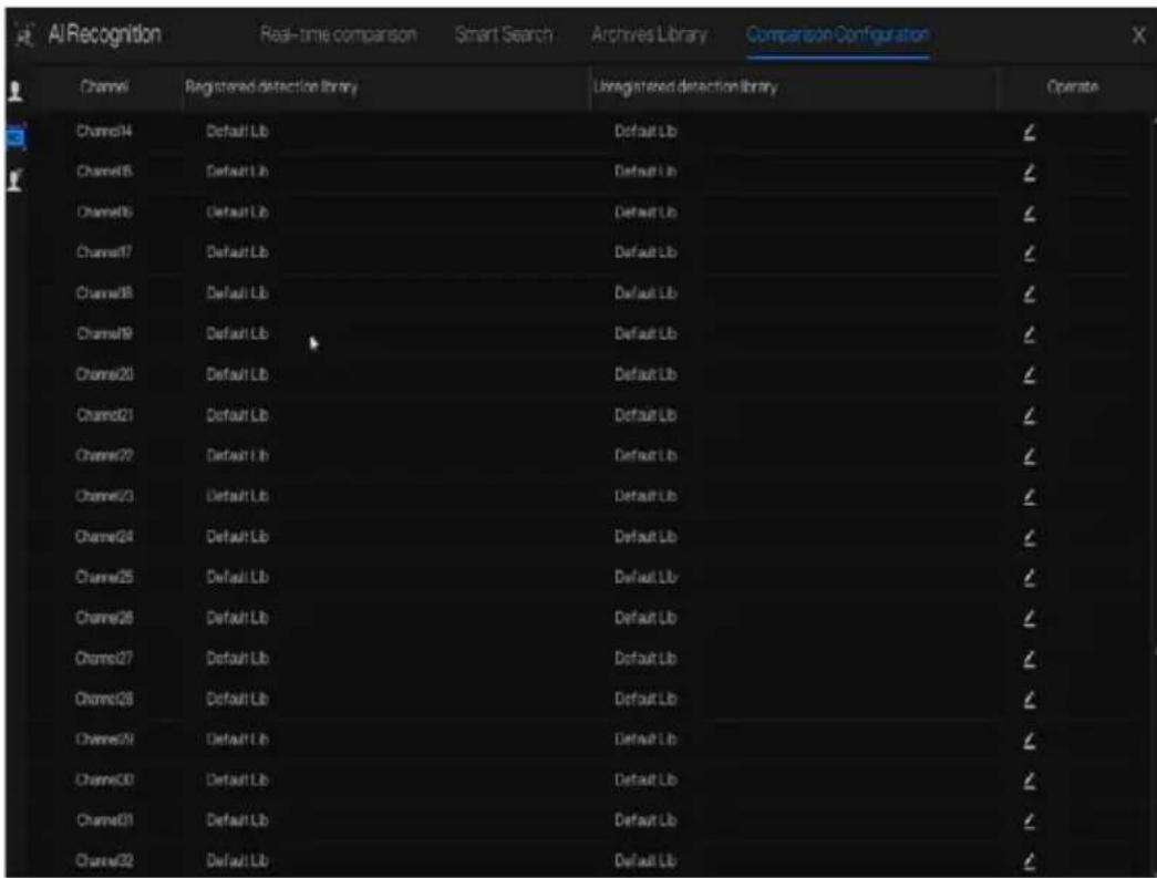
Figure 6-38 Strategy
----End
6.4.4.3 Temperature Comparison
At comparison configuration interface, click to enter the temperature configuration, as shown in Figure 6-39.
Figure 6-39 Temperature comparison
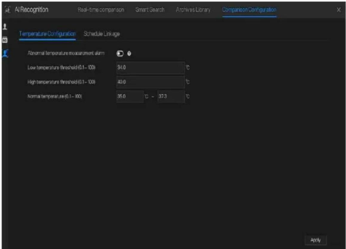
At temperature comparison interface, users can set low temperature threshold, high temperature threshold, and normal temperature.
Abnormal temperature measurement alarm, when it is turned on, the temperature below the low threshold and above the high temperature threshold will generate abnormal temperature alarm. When it is turned off, body temperatures below the low threshold and above the high threshold are discarded.
Figure 6-40 Schedule linkage

Enable alarm, set the schedule linkage, it will send alarm information if the temperature is higher than low threshold and lower the normal temperature, or higher than normal temperature and lower than high threshold.
----End
6.4.4.4 Mask Detection Configuration
Figure 6-41 Mask detection configuration

Enable mask detection, choose the mode (with or without a mask). Set the confidence degree, the default value is 90.
Figure 6-42 Schedule linkage

Enable the alarm, the real-time comparison can show if someone wears a mask or not.
Choose event actions, and set the schedule.
Click "Apply" to save the settings.
----End
6.4.4.5 Personnel Count Configuration
Figure 6-43 Personnel count configuration

Enable personnel count to start the people counting.
Enable OSD to show OSD (OSD is displayed on the auxiliary screen, you need to start the auxiliary screen in "System> Auxiliary Screen" before displaying).
Select the counting clear interval (never, 10 minutes, half an hour, 1 hour, 12 hours, 1 day).
Set correction value, Configure the calibration value to start the manual calibration of the personnel count value.
Alarm threshold: when the people count reaches the threshold, an alarm is activated. Alarm interval: 10s, 20s, 30s, 40s, 50s, 60s.
Click "Apply" to save the settings.
Figure 6-44 Schedule linkage
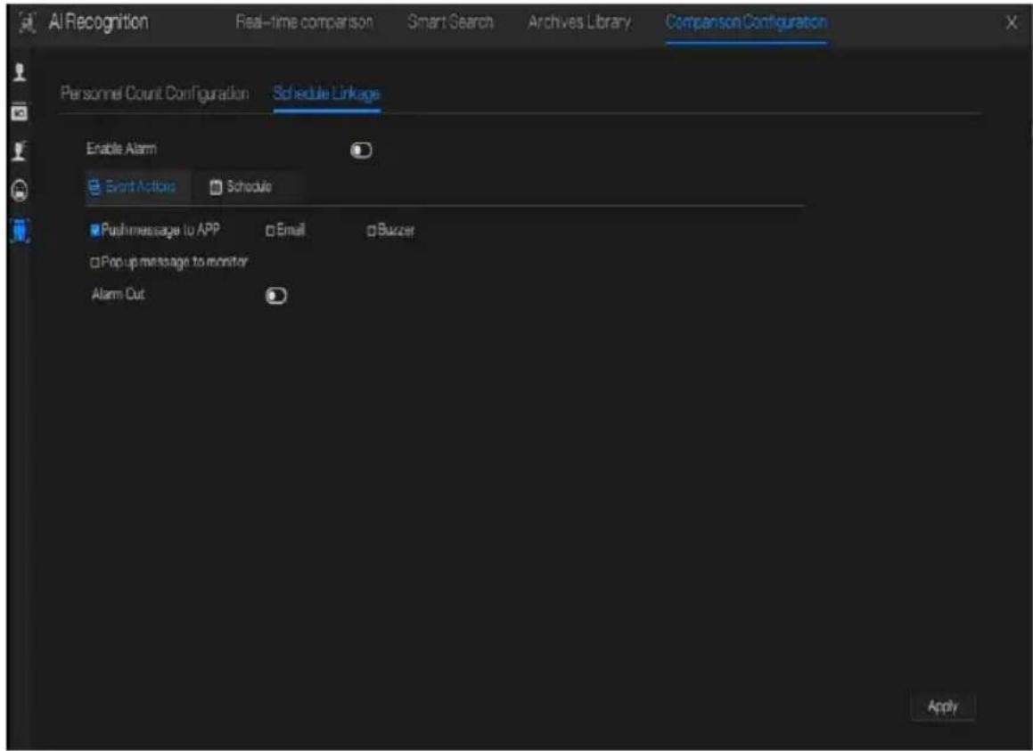
Set schedule linkage action to alarm.
----End
6.5 Attendance (Only for Some Models)
6.5.1 Attendance Data
Click to enter attendance data interface, as shown in Figure 6-45.
Figure 6-45 Attendance data

Operation Steps
Step 1 Tick the attendance library.
Step 2 Choose time mode, such as today, this week, this month and custom time.
Step 3 Choose search type, such as attendance summary and attendance details.
Step 4 Click search, the result will show in interface.
Step 5 Click Export to export the query result.
---End
6.5.2 Attendance Management
In attendance management, users can set attendance rule, library and check point, as shown in Figure 6-46.
Figure 6-46 Attendance rule settings
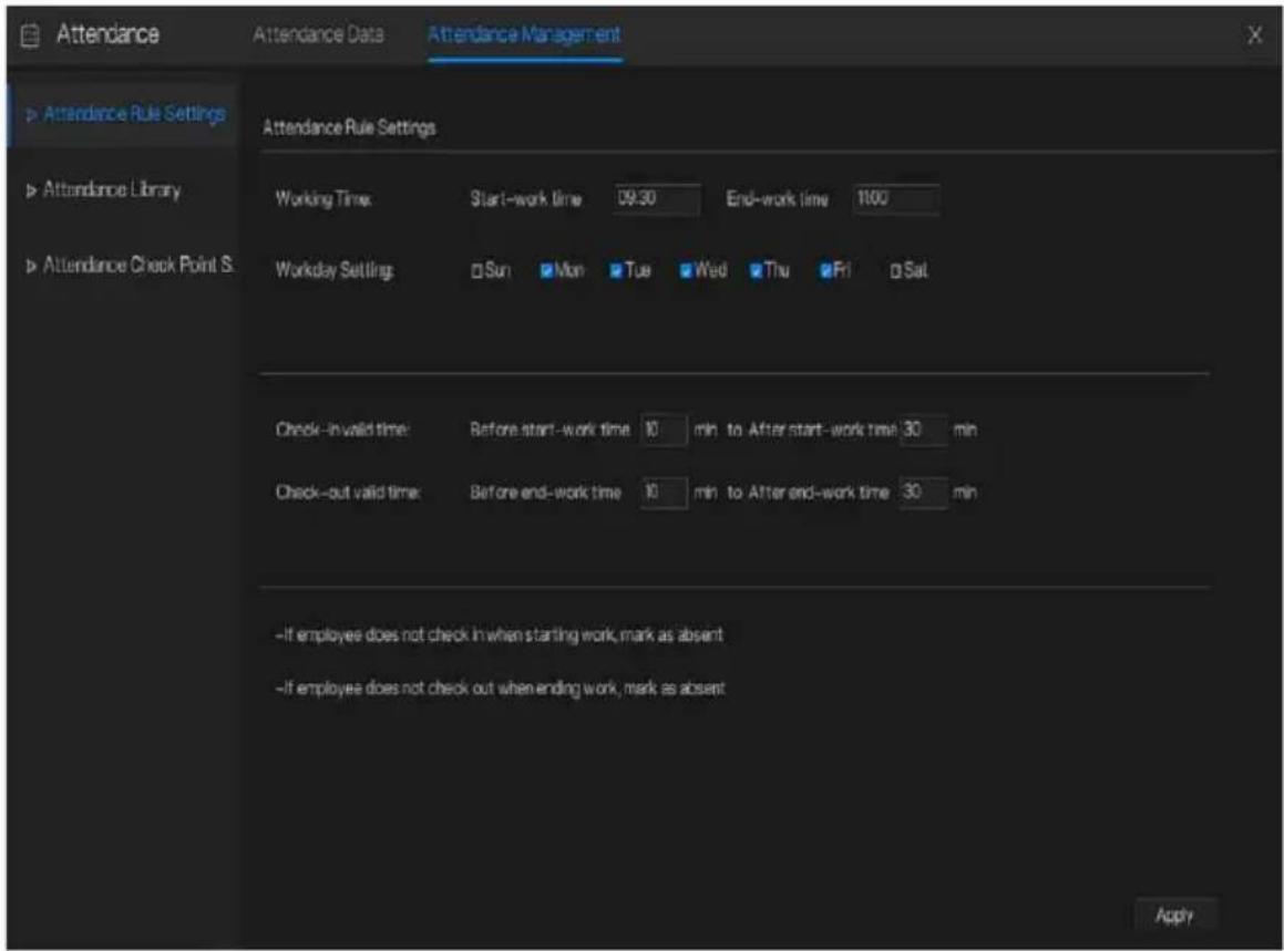
Operation Steps
Step 1 Set start work time and end work time.
Step 2 Tick the workday
Step 3 Set valid time of check in and check out.
Step 4 Click Save to save the setting.
Attendance library
Step 1 Click Attendance Library to add library, the attendance library can call the face database directly.
Figure 6-47 Attendance library

Step 2 Tick the library and click Add to add to attendance library. If you want to modify the library.
Step 3 click Database management management to modify
parameter.
Step 4 Click Save to save the setting.
Attendance check point settings:
Step 1 Click Attendance check point settings to set point, as shown in Figure 6-48.
Figure 6-48 Attendance check point setting

Step 2 Click edit check point setting, as shown in Figure 6-49
Figure 6-49 Check point

Step 3 Enable the function, set similarity and tick the library, all face detection cameras can be set the check points
Step 4 Click OK to save the setting.
---End
6.6 Thermal Temperature (Only for Some Models)

NOTE
The thermal temperature function is only available for some devices. If the current device does not have the function, please ignore it.
6.6.1 Temperature Parameters
Temperature parameters include: temperature unit, ambient type, ambient temperature, cavity temperature, correctional coefficient and area temperature display mode.
Operation Procedure
Step 1 Choose Thermal >Temperature Parameters.
The Temperature Parameters page is displayed, as shown in Figure 6-50.
Figure 6-50 Temperature Parameters interface
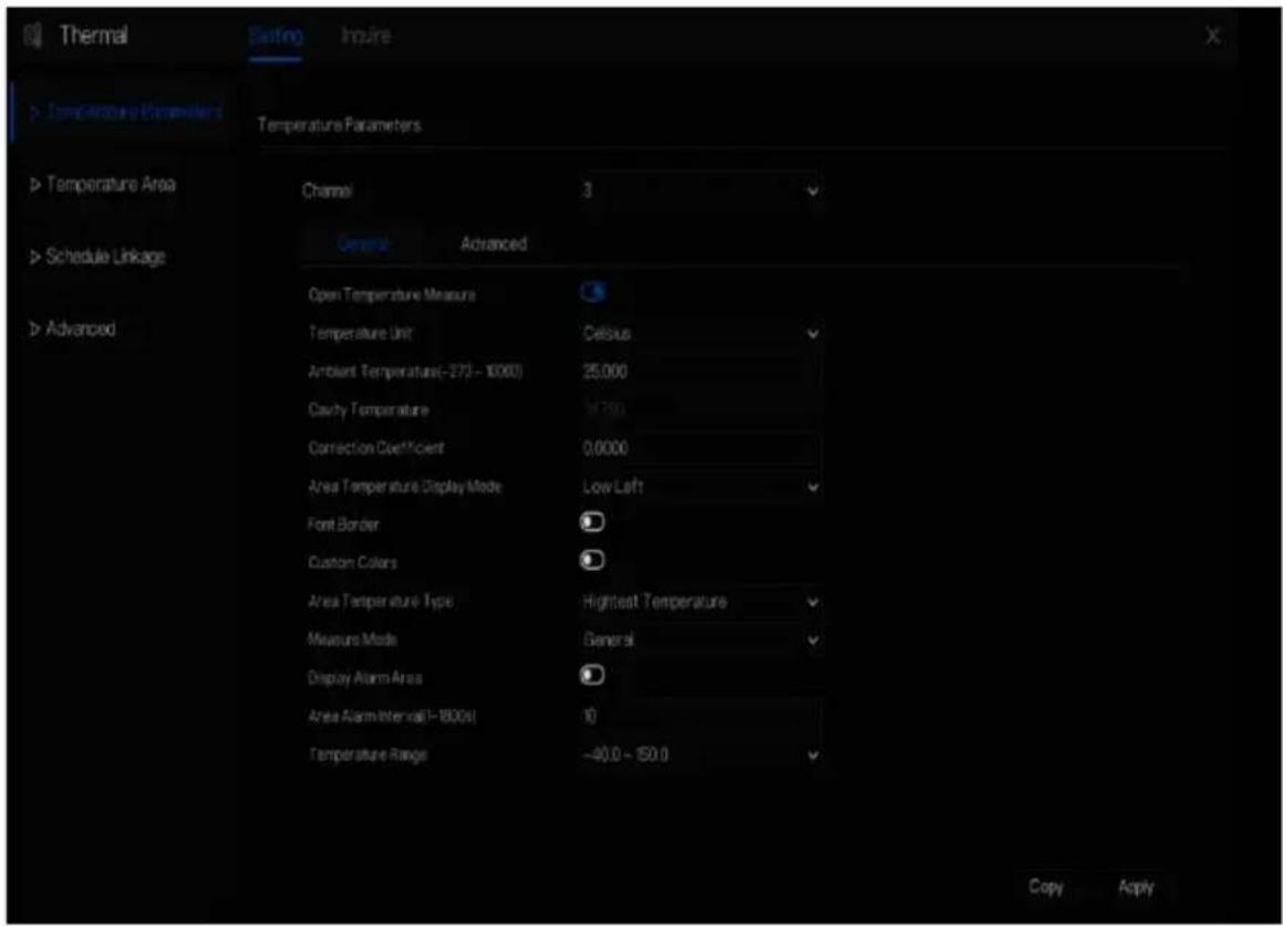
Step 2 Set the parameters according to Table 6-1.
Table 6-1 Temperature parameters
| Parameter | Description | Setting |
| Open Temperature Measure | Enable temperature measure. | |
| Temperature Unit | Celsius and Fahrenheit temperature units are available. | [Setting method]Select a value from the drop-down list box.[Default value]Celsius |
| Ambient Temperature | The ambient temperature of camera. It is set when ambient is outside. | [Setting method]Enter a value manually. |
| Cavity Temperature | The cavity temperature of camera. | N/A |
| Correction Coefficient | Correction coefficient is refer to the deviation of measured object temperature and actual temperature.For example:1. The measured object temperature is 30, and actual temperature is 37, so the correction coefficient should be 7.2. The measured object temperature is 37, and actual temperature is 30, so the correction coefficient should be -7. | [Setting method]Enter a value manually.[Default value]0.00 |
| Area Temperature Display Mode | The display position of temperature information on the live-video image. | [Setting method]Select a value from the drop-down list box.[Default value]Low left |
| Font Border | The font will be bolded. | [Setting method]Enable or disable[Default value]disable |
| Custom Colors | Enable to custom the color, there are nine colors chosen. | [Setting method]Enable or disable[Default value]disable |
| Area Temperature Type | There are three types of area temperature. | [Setting method]Select a value from the drop-down list box.[Default value]Highest Temperature |
| Measure Mode | There are two types measure modes. | [Setting method]Select a value from the drop-down list box.[Default value]General |
| Display Alarm Area | N/A | [Setting method]Enable or disable[Default value]disable |
| Area Alarm Interval | N/A | [Setting method]Enter a value manually ranges from 1 to 1800.[Default value]10 |
Figure 6-51 Advanced parameter
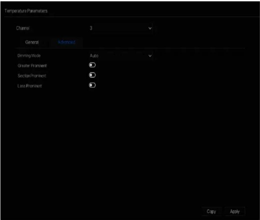
Table 6-2 Advanced parameters
| Parameter | Description | Setting |
| Dimming Mode | There are auto and manual modes. It will show on temperature item. | [Setting method]Select a value from the drop-down list box.[Default value]Auto |
| Greater Prominent | Enable that, the image will show the setting color if the temperature is higher than set value. | [Setting method]Enter a value manually.Choose one color to show. |
| Section Prominent | Enable that, the image will show the setting color if the temperature is between minimum and maximum temperature. | [Setting method]Enter a value manually.Choose one color to show. |
| Less Prominent | Enable that, the image will show the setting color if the temperature is lower than set value. | [Setting method]Enter a value manually.Choose one color to show. |
Step 3 Click Copy to copy the same settings to others thermal cameras.
Step 4 Click Apply.
Step 5 The message "Apply success" is displayed, the system saves the settings.
----End
6.6.2 Temperature Area
Operation Procedure
Step 1 Choose Thermal >Temperature Area.
The Temperature Area page is displayed, as shown in Figure 6-52
Figure 6-52 Temperature area and alarm configuration
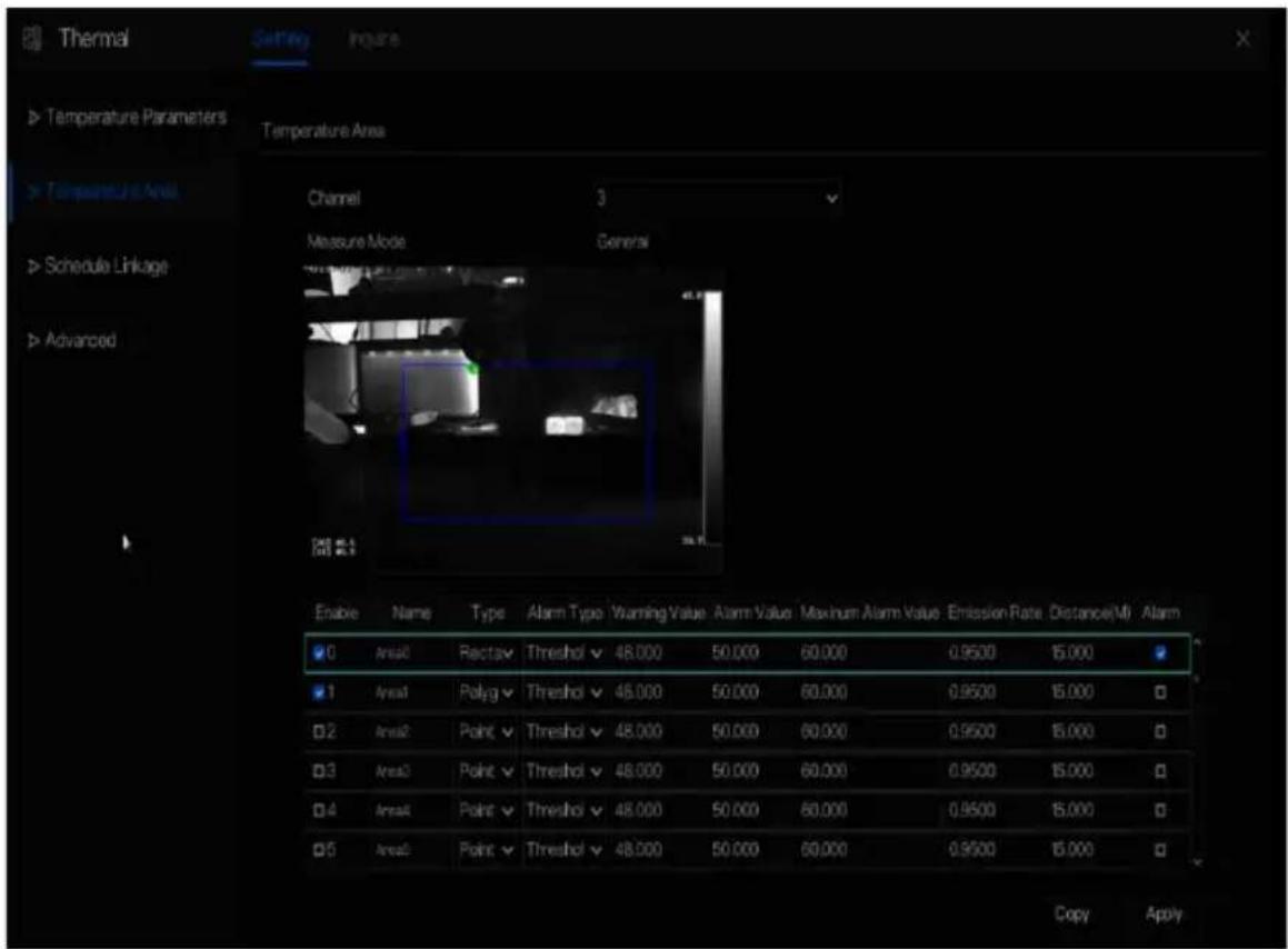
Step 2 Set the parameters according to Table 6-3
Table 6-3 Temperature area and alarm configuration
| Parameter | Description | Setting |
| Channel | N/A | [Setting method]Select a value from the drop-down list box.[Default value]1 |
| Measure Mode | Set at temperature parameter interface. | N/A |
| PTZ Area(only use for PTZ cameras) | Choose or set the preset, adjust the camera with PTZ keyboard.The all presets can set 20 areas to alarm | Set the preset manually, or select an existing preset in the drop-down list. |
| Enable | Tick to enable alarm areas. | N/A |
| ID | It ranges from 0 to 19. | N/A |
| Name | Area name of temperature area. | [Setting method]Enter a value manually. |
| Type | Type of temperature area.ID 0 is default rectangle area, which is full screen.There are 20 areas can be set, these are from 0 to 19 area. | [Setting method]Select a value from the drop-down list box.[Default value]Rectangle/Point |
| Alarm Type | Threshold alarm and Temperature difference alarm are available for alarm type. | [Setting method]Select a value from the drop-down list box.[Default value]Threshold alarm |
| Warning Value | Camera will warn when the surveillance object temperature reaches the warning value. | [Setting method]Enter a value manually.[Default value]48.00 |
| Alarm Value | Camera will alarm when the surveillance object temperature reaches the alarm value. | [Setting method]Enter a value manually.[Default value]50.00 |
| Maximum Alarm Value | The maximum value of the alarm range, if the alarm value is exceeded, no alarm will be generated. | [Setting method]Enter a value manually.[Default value]60.00 |
| Emission Rate | The emission rate is the capability of an object to emit or absorb energy.The emission rate should be set only when the target is special material. | [Setting method]Enter a value manually.[Default value]0.95 |
| Distance(M) | The distance between camera and target. | [Setting method]Enter a value manually.[Default value]15NOTEEnter actual distance when the distance between camera and target is less than 15 m. Enter 15 when the distance between camera and target is great than or equal to 15 m. |
| Alarm | Open or close the alarm output and linkage of area. | [Setting method]Tick the alarm areas |
Step 3 Set temperature area.
- Tick an area ID.
- Select type from drop-list.
- Press and hold the left mouse button, and drag in the video area to draw a temperature area. Right-click to finish the area selection.
- Click Apply, the message “Apply success” is displayed, the temperature area is set successfully.
Delete a temperature area:
- Select an area ID.
- Click the temperature area and right-click.
-
Unselected the area ID.
-
Click Apply, the message "Apply success" is displayed, the temperature area is deleted successfully.
Step 4 Click Apply.
Step 5 The message "Apply success" is displayed, the system saves the settings.
----End
6.6.3 Schedule Linkage
Operation Procedure
Step 1 Choose Thermal > Schedule Linkage
The Schedule Linkage page is displayed, as shown in Figure 6-53.
Figure 6-53 Schedule Linkage

Step 2 Tick the output channel.
Step 3 Enable “Alarm Record”, “E-mail” button.
Step 4 Set schedule linkage.
Figure 6-54 Schedule

Method 1: Click left mouse button to select any time point within 0:00-24:00 from Monday to Sunday as shown in Figure 6-53.
Method 2: Hold down the left mouse button, drag and release mouse to select the alarm time within 0:00-24:00 from Sunday to Saturday.

NOTE
When you select time by dragging the cursor, the cursor cannot be moved out of the time area. Otherwise, no time can be selected.
Method 3: Click in the alarm time page to select the whole day or whole week.
Deleting alarm time: Click again or inverse selection to delete the selected alarm time.
Step 5 Click Apply.
Step 6 The message "Apply success" is displayed, the system saves the settings.
----End
6.6.4 Advanced
Operation Procedure
Step 1 Choose Thermal > Advanced to enter the advance interface, as shown in Figure 6-55.
Figure 6-55 Advanced

Step 2 Select the temperature collection interval from the drop-list.
Step 3 Click Apply.
Step 4 The message "Apply success" is displayed, the system saves the settings.
----End
6.6.5 Inquire
Operation Procedure
Step 1 Choose Thermal > Inquire to enter the inquire interface, as shown in Figure 6-56.
Figure 6-56 Inquire
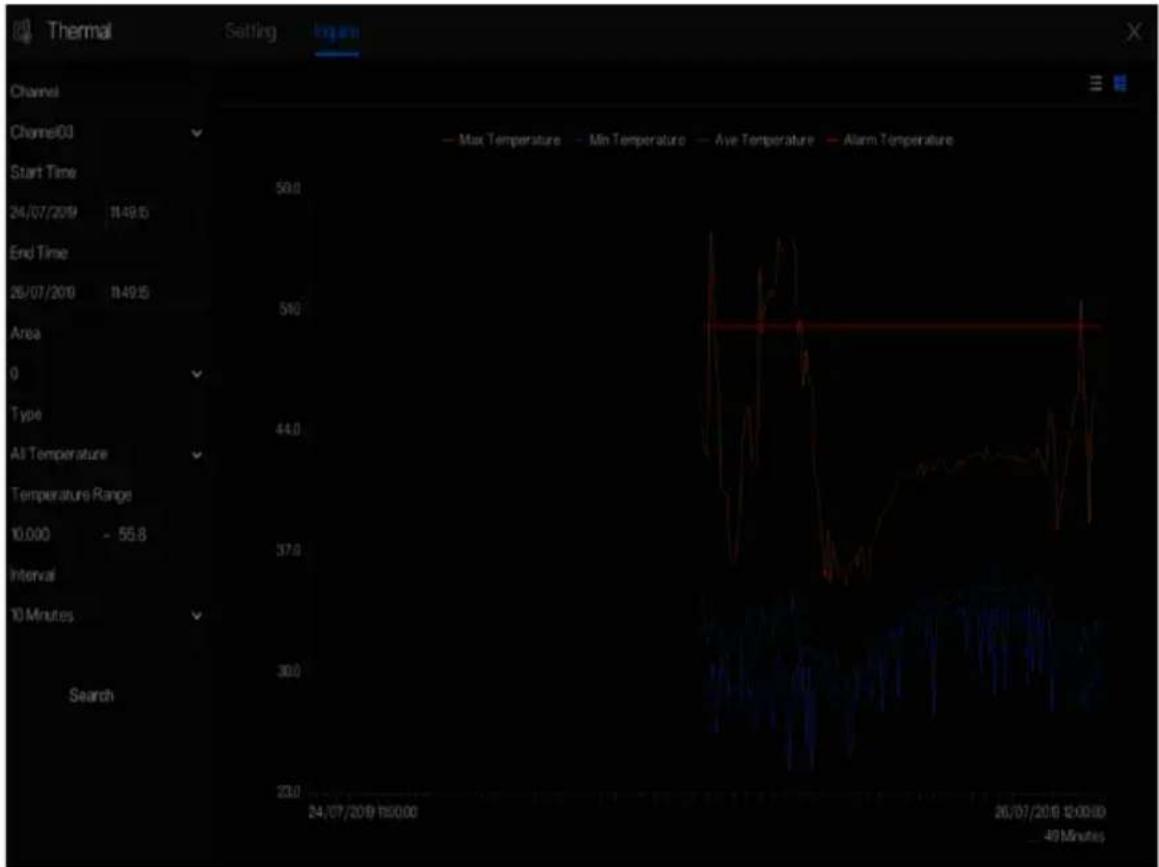
Step 2 Choose a channel is thermal camera.
Step 3 Set the start and end time.
Step 4 Choose the area, which is set at the temperature area interface. The default area is 0(full screen).
Step 5 Choose the type of temperature, set the temperature range.
Step 6 Choose the interval of showing, click Search to show the result, there are two modes to show result, list or picture.
----End
6.7 Channel Information
Click the 📄 will show as Figure 6-57, tick the Channel or Encode, the information will show in live video screen.
Figure 6-57 Channel information

----End
6.8 Main Menu
Right-click on the UI screen, the main menu as shown in Figure 6-58. The main menu includes
Channel, Record, Network, Alarm and System.
Figure 6-58 NVR main menu

----End
7 UI System Setting

NOTE
Different devices may have different functions, please refer to actual products.
7.1 Channel Management
IP cameras can directly be connected to input channels of the NVR by plugging in POE port.
When IP cameras are insufficient, the NVR can automatically search for and add IP cameras or
manually add cameras in the same Local Area Network (LAN).
Channel management includes Add or Delete Camera, Encode, Sensor Setting, OSD, Privacy
Zone, ROI, Microphone, Human Thermometer, Smart, and Intelligent Tracking.
7.1.1 Camera
Operation Description
Click Channel in the main menu to access the camera management screen, as shown in Figure 7-
1 There are four modes for adding cameras, manually add, batch add, search to add, POE add,
and automatic add.
Figure 7-1 Channel management screen


: Modify device parameters, remote channel is based on cameras (human body
temperature has two remote channels, fisheye cameras have four remote channels) as shown in Figure 7-2.
Figure 7-2 Modify device parameter

----End
7.1.1.1 Add Camera Automatically
The NVR can add automatically cameras to the camera list.
Operation Methods
Method 1: Click Start Search button, the cameras in the same network as your recorder will show in list, the search will be lasting for 20 seconds. Input username and password (the default value both are admin) click Add Devices Method 2: Select the cameras you want to add, and click Add and cameras would be added to the camera list.
Tick the online non-onvif channels at list and click to access the directory of software; it would to update the channels at once.

NOTE
- On the camera management screen, check the status of channels in the camera list. If the status of a channel is, this camera is online. If the status of a channel is, this camera is offline.
● The added cameras should be the same network as NVR.
----End
7.1.1.2 Add Camera Manually
Operation Steps
Step 1 Click add devices as shown in Figure 7-3.
Figure 7-3 Add camera screen

Step 2 Input IP address, port, user name and password of this camera. Double click the online camera IP to copy its configuration. Quick change of other channel's parameters can be done.
Step 3 Select a protocol from the drop-down list(ONVIF, Private, custom protocols). Remote channel is only used for multi channels cameras, such as human temperature cameras, fisheye cameras, and so on.
Step 4 Click , the camera is added successfully.

NOTE
If all channels of the NVR are connected by cameras, please delete the cameras that you don't need, so that you can add more cameras.
If an IP camera is added manually, input the correct username and password of the camera below the online device list. The camera will be added successfully. If not the camera would be shown on list at offline.
The protocol can be chosen the custom protocols these are set at protocol interface.
The user can click the added channel to copy the information to save the time, you can just need to modify difference information, such as the remote channel.
----End
7.1.1.3 Add Camera by RSTP
If the user wants to add the different protocol cameras to NVR, you can set the protocol management, and add cameras one by one, as shown in Figure 7-4.
Figure 7-4 Protocol management
![System Channel Record Alarm Network System Camera Protocol Management Custom Protocol Custom Protocol 1 Protocol Name Custom 1 Stream Type Main Stream Sub Stream Protocol Type RTSP RTSP Port 554 554 Path Example[Type]/[IP Address][Port]/[Path]; Apply](/content/2026/05/1015136/images/739ce27ac9532e2366e6ab2ff7e065b84867b1ed91aafe539274b7d0aa7dbf2f.jpg)
Step 1 Click Channel > Camera > Protocol Management.
Step 2 Choose the custom protocol from the drop-down list, there are 16 kinds of protocols can be set.
Step 3 Input the protocol name.
Step 4 Tick main stream and sub stream. The main stream shows image on full screen live video.
The sub stream shows image on split screen. If you just tick main stream and the channel will not show image on split screen.
Step 5 Choose the type of protocol, the default value is RTSP.
Step 6 Input the port of the IP camera.
Step 7 Input the path (it may vary with different camera models).
Step 8 Click Apply to save the settings.

NOTE
Choose the protocol from the drop-down list, the protocol is set at protocol management interface. The cameras should be confirmed to the protocols.
----End
7.1.1.4 Delete Camera
Operation Steps
Step 1 Select a camera to delete in the camera list and click the delete confirmation message screen is displaying, as shown in Figure 7-5.
Figure 7-5 Delete confirmation message

Step 2 Click , the camera will be deleted successfully.
7.1.1.5 Operate Camera
At camera list, click to operate camera as shown in Figure 7-6, users can update, reboot and reset the camera immediately.
Figure 7-6 More operation
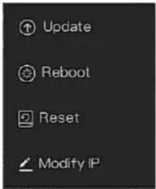
Step 1 Click Update, pop-up window to select software, as shown in Figure 7-7.
Step 2 Set the directory click to update camera.
Figure 7-7 Select directory of software

Step 3 Click Reboot, message “Are you sure to reboot?” would show, click OK to reboot the camera.
Step 4 Click Reset, message “Are you sure to reset?” would show, users can enable the retain IP address function. Click to reboot the camera.
Step 5 Tick the cameras with non-onvif protocol and cameras are online, click Update to update all cameras at once.
Step 6 IP address of the online camera can be modified, click Modify IP to modify as shown in following figure, input the new IP address and subnet mask.

NOTE
Update need upload the firmware by flash driver.
----End
7.1.2 Encode Parameter
The system allows setting the stream information, encoding type, resolution, frame rate, bitrate control, bitrate and quality for cameras in a channel in Encode Parameter screen.
Operation Description
Click Encode in the main menu or Menu of the channel management screen and choose Encode to access the Encode screen, as shown in Figure 7-8.
Figure 7-8 Encode screen
![System Channel Record Alarm Network System Camera Encode Channel [1]Channel01 OSD Privacy Zone ROI Microphone Human Thermometer Smart Intelligent Trucking Stream Information Video Format Audio Encode Type Resolution Frame Rate(tpa) IFrame Interval(Frame) Bitrate Type Ultrate(kbps) Quality Smart Enco…](/content/2026/05/1015136/images/f733d46ad0db310621fe1947fb7c467cfce8453ab691a0cb8c28f2d4c789de06.jpg)
Operation Steps
Step 1 Select a channel from the drop-down list of channel.
Step 2 Set video format, audio encode type, resolution, frame rate, bitrate type, bitrate size and quality from the drop-down lists.
Step 3 Click Copy and select channels or tick all, then click OK to apply the parameter settings to cameras in selected channels, click Apply to save encode parameter settings.
----End
7.1.3 Sensor Setting
Sensor setting refers to basic attributes of pictures, it includes the brightness, sharpness, contrast and saturation. You can set picture parameters for each channel based on scene.
Operation Description
Click Sensor Setting in the main menu or click menu of the channel management screen and choose Sensor Setting to access the Sensor Setting screen, as shown in Figure 7-9.
Figure 7-9 Sensor setting screen
![System Channel Record Alarm Network System Sensor Setting 2022-04-24 17:54:48:59 Channel [1]Channel01 Image Scene Exposure White Balance Day/Night Noise Reduction Enhance Image Scene Default Brightness - + 50 Sharpness - + 50 Contrast - + 50 Saturation - + 50 Default Apply](/content/2026/05/1015136/images/6775b407fde76fe2b11bd89884d3181c8e0b51a0488f685feee719cbf887a6e2.jpg)
The Sensor Setting are as follows:
• Brightness: it indicates brightness or darkness of an image.
- Sharpness: it indicates picture's clarity.
• Contrast: it refers to the brightest white and darkest black in an image.
• Saturation: it indicates brilliance of the picture color.
Other parameters are sensor settings of IP cameras, like scene, exposure, white balance, day-night, noise reduction, enhance image, zoom focus, etc.
- Scene: it includes indoor, outdoor, default. Mirror includes normal, horizontal, vertical, horizontal + vertical.
- Exposure: it includes mode, max shutter, meter area and max gain.
• White balance: it includes tungsten, fluorescent, daylight, shadow, manual, etc.
UI System Setting User Manual
• Day-night: users can transit day to night, or switch mode.
• Noise reduction: it includes 2D NR and 3D NR.
• Enhance image: it includes WDR, HLC, BLC, defog and anti-shake.
• Zoom focus: users can zoom and focus.
Operation Steps
Step 1 Select a channel from the drop-down list of channel.
Step 2 Select scene from the drop-down list. The default values of picture parameters vary with scenarios.
Step 3 Set parameters.
Step 4 Click Default to factory settings, click to save Apply Settings.
----End
7.1.4 OSD Settings
Click OSD in the main menu or menu of the channel management screen and choose OSD to access the OSD screen, as shown in Figure 7-10.
Figure 7-10 OSD setting screen
![System Channel Record Alarm Network System ► Camera ► Encode ► Sensor Setting ► OSD ► Privacy Zone ► ROI ► Microphone ► Human Thermometer ► Smart ► Intelligent Tracking OSD Time 04:24.12.59.02 Sum Channel [1]Channel01 Time Channel Name Channel01 Copy Apply](/content/2026/05/1015136/images/3e3d68cd8858f6ee6c19ec921796656e6e2d0afcdb1dc526c0ba46622ff559e1.jpg)
Operation Steps
Step 1 Select a channel from the drop-down list of channel.
Step 2 Click 📄 to Time to enable or disable OSD time setting.
Step 3 Click to Name to enable or disable OSD channel setting.
Step 4 Set the channel name.
Step 5 In the video window, click and drag time or channel to move to a location.
Step 6 Click Copy channels, then click to apply to OK settings to cameras in selected channels, click Apply SD settings.
----End
7.1.5 Privacy Zone
The system allows you to mask images in a specified zone and which is called privacy zone.
Operation Description
Click Privacy Zone in the main menu or menu of the channel management screen and choose privacy zone to access the Privacy Zone screen, as shown in Figure 7-11.
Figure 7-11 Privacy zone screen
![System Channel Record Alarm Network System Camera Encode Sensor Setting OSD Privacy Zone ROI Microphone Human Thermometer Smart Intelligent Tracking Privacy Zone 02-04-24 19:00:12 Bus Channel [1]Channel01 - Click and hold left button and drag to select an area - Double click an area to delete it - S…](/content/2026/05/1015136/images/86977b86bcb8975a4e88d115883f6fd0d23a23129af0ed86a8403cad0742fcdd.jpg)
Operation Steps
Step 1 Select a channel from the drop-down list of channel.
Step 2 In the video window, hold down and drag the left mouse button to draw a privacy area.
Step 3 Click Copy and select channels or tick all, then click OK to apply the privacy settings to cameras in selected channels, click Apply Privacy settings.
Step 4 Double click privacy area to delete setting.
----End
7.1.6 ROI
Click ROI in the main menu or menu of the channel management screen and choose ROI to access the ROI screen, as shown in Figure 7-12.
Figure 7-12 ROI
![System Channel Record Alarm Network System Camera Encode Sensor Setting OSD Privacy Zone ROI Microphone Human Thermometer Smart Intelligent Tracking ROI 22:04:24 12:29:34 3ns Channel [1]ChannelID Stream Main Stream Area ID 1 Enable Level 5 Area Name - Note: Max size 50% - Right click to remove the z…](/content/2026/05/1015136/images/ebd1fbd0e22f832b7d1e862af10d8f08c8043711f7871ca6cd2af8ed27891584.jpg)
Table 7-1 RIO parameter
| Parameter | Description | Setting |
| Stream | Stream ID. | [Setting method]Select a value from the drop-down list box.[Default value]Stream 1 |
| Enable | Enable the ROI | [Setting method]Click the button.[Default value]OFF |
| Area ID | ROI area ID, there are 8 area | [Setting method]Select a value from the drop-down list box.[Default value]1 |
| Level | The measure result of ROI. The higher the grade, the clearer the area inside and the more vaguer the area outside. There are five levels. | [Setting method]Select a value from the drop-down list box.[Default value]5 |
| Area Name | The marked name used for areas. | [Setting method]Enter a value manually. The value cannot exceed 32 bytes. |
----End
7.1.7 Microphone (Only for Some Models)
Click Microphone in the main menu or menu of the channel management screen and choose Microphone to access the Microphone screen, as shown in Figure 7-13.
Figure 7-13 Microphone
![System Channel Record Alarm Network System Camera Encode Sensor Setting OSD Privacy Zone ROI Microphone Human Thermometer Smart Intelligent Tracking Microphone Channel [1]Channel01 Microphone Microphone Type Line In Microphone Volume - 50 + 50 Apply](/content/2026/05/1015136/images/4856ecd8c842c652db72838310fb727d0ea97027e19812fd7e457b1d0a22497b.jpg)
Table 7-2 Microphone
| Parameter | Description | Setting |
| Enable Microphone | Indicates whether to enable the microphone function. | [Setting method]Click the button on to enable microphone. |
| Microphone Type | Microphone types include:• Line InAn active audio input is required. | [Setting method]Select a value from the drop-down list box. |
| Microphone Volume | Allows you to adjust the microphone volume. | [Setting method]Slide the slider left or right.[Default value]50NOTEThe value ranges from 0 to 100. |
----End
7.1.8 Human Thermometer (Only for Some Models)
Click Human thermometer in the main menu or menu of the channel management screen and choose Human thermometer to access the Human thermometer screen, as shown in Figure 7-14.
Figure 7-14 Human thermometer
![System Channel Record Alarm Network System Parameter Configure Thermal Mapping Thermal Calibration 2023-04-24 15:00:54 Channel [5]ChannelDS Remove All Face Detection Temperature Param Low temperature als Normal temperature. High temperature als Schedule Face Detection Display Trace Info Mode1 Show D…](/content/2026/05/1015136/images/9d6be5888c95d4d05bc000a2f17078552be00811834bea023258353c9fe8b082.jpg)
7.1.8.1 Parameter Configuration
Table 7-3 Human thermometer
| Parameter | Description | Setting |
| Face detection | Detect face of human | [Setting method]Enable[Default value]On |
| Display trace | Display the information of tracing. OFF, mode 1 and mode 2 | [Setting method]Enable the button[Default value]Mode 1 |
| Show detection area | Enable, the live video will show area of detection. | [Setting method]Enable |
| Confidence coefficient | Face detection sensitivity, the value range is high, medium,low, the larger the value is, the higher the sensitivity. The higher the sensitivity value is, the higher the detection rate will be, but the more false detection may occur, such as the false detection of the patterns on pedestrian clothes to adult faces. | [Setting method]Choose from drop -list [Default value]Medium |
| Area ID | There are 8 areas can be set to detect temperature.Choose from the drop-list, left-click to draw the area, right-click to finish the set. | [Setting method]Choose from drop -list [Default value]1 |
| Face pixel min (1-2000) | When the pixel of the face in the image is less than the set value (the minimum pixel for face recognition), it is not captured. | [Setting method]Input a number from 1 to 2000[Default value]30 |
| Face pixel max (1-2000) | When the pixel of the face in the image is more than the set value (the maximum pixel for face recognition), it is not captured. | [Setting method]Input a number from 1 to 2000[Default value]70 |
| Image matting quality | The quality of snap image, There are three mode can be chosen, such as low, mid and high. | [Setting method]Choose from drop list. [Default value]Medium |
| Snapshot mode | There are two types, timing and optimal. | [Setting method]Choose from drop -list [Default value]Timing |
| Upload image interval | The snapshot mode is optimal, set the interval. | [Setting method]Input a number from 1 to 10[Default value]5 |
| Snapshot count | At optimal mode, set the number of snapshot image | [Setting method]Input 1 |
| Yaw degree(0-90) | Both eyes appear on the screen, offset in the left and right direction | [Setting method]Input a number from 0 to 90[Default value]30 |
| Tilt degree(0-90) | The face is deflected, and both eyes cannot appear in the picture. | [Setting method]Input a number from 0 to 90[Default value]30 |
| Pitch degree(0-90) | Face is moving up and down | [Setting method]Input a number from 0 to 90[Default value]30 |
| FTP upload image matting | Configuration > Network Service > FTP, set FTP related parameters, the captured picture will be sent to the set FTP location | [Default value]Disable |
| FTP upload whole image | Capture a picture and send a whole image. | [Default value]Disable |
| OSD over snapshot | Enable, the snapshots will record the temperature, as shown in figure. | [Default value]Disable |
Figure 7-15 Temperature parameters

Table 7-4 Temperature parameters
| Parameter | Description | Setting |
| Temperature Unit | Celsius and Fahrenheit temperature units are available. The unit is link to all temperature parameter, please modify the linkage value. | [Setting method]Select a value from the drop-down list box.[Default value]Celsius |
| Ambient Temperature | The ambient temperature of camera. | [Setting method]Enter a value manually. |
| Cavity Temperature | The cavity temperature of camera. | N/A |
| Correction Coefficient | Correction coefficient refers to the deviation of measured object temperature and actual temperature.For example:1. The measured object temperature is 30, and actual temperature is 37, so the correction coefficient is 7.2. The measured object temperature is 37, and actual temperature is 30, so the correction coefficient is -7. | [Setting method]Enter a value manually.[Default value]0.00 |
| Mount distance | The actual distance between the detection person and the device, it is set to facilitate the temperature measurement accuracy. | [Setting method]Select a value from the drop-down list box.[Default value]General |
| Face color | Enable, if the camera detect the face and the face will be covered color, normal is yellow, and high temperature is red, as shown in figure. | [Default value]Disable |
| Environment adaptation | Enable, the device will restart the temperature if the ambient temperature of camera varies greatly. It is recommended not to open. | [Default value]Disable |
| Abnormal temperature display | Enable, the measure temperature is lower than 34 °C will show on OSD.Disable, the measure temperature is lower than 34 °C will not show on OSD. | [Default value]Disable |
| Temperature area | Two modes, shows at themal channel. Mode 1 is full face area, mode 2 is forehead area. | [Setting method]Select a value from the drop-down list box.[Default value]Mode 1 |
UI System Setting User Manual
| Parameter | Description | Setting |
| Temperature measure mode | Two modes, mode 1 is suitable for high air temperature, if the forehead temperature is less than 31 °C, not to show as body temperature. Mode 2 is suitable for low air temperature, if the forehead temperature is at 30-31 °C, so it will show as body temperature too. | [Setting method] Select a value from the drop-down list box. [Default value] Mode 1 |
| Normal temperature range | Set the temperature range, when the detection is out of range, it will be alarming. | [Setting method] Enter a value manually. [Default value] 36 ~37.3 |
Low temperature alarm linkage / Normal temperature linkage / High temperature linkage: when the detection temperature is meet the setting, you can set the linkage action to alarm, as shown in Figure 7-16.
Figure 7-16 Linkage action

Set the alarm linkage schedule.
Click Apply to save the settings.
----End
Figure 7-17 Thermal mapping
![System Channel Record Alarm Network System Parameter Configure Thermal Mapping Thermal Calibration Channel 2022-04-24 18:10:56.5µm Channel [5]Channel05 2022-04-24 18:10:56.5µm Horizontal Shift(%) 0.00 Vertical Shift(%) 0.00 Mapping Point Point Three Apply](/content/2026/05/1015136/images/9e07f4ace918337e69d8290b48051b734d406ce42db114b9c899db8a3beb9230.jpg)
Table 7-5 Parameter of thermal mapping
| Parameter | Description | Setting |
| Zoom in /zoom out. | [Setting method]Click the button | |
| Near focus / far focus. | [Setting method]Click the button | |
| Horizontal shift (%) | The points move small at horizontal direction. | [Setting method]Enter a value manually.[Default value]0.00 |
| Vertical shift (%) | The points move small at vertical direction. | [Setting method]Enter a value manually.[Default value]0.00 |
UI System Setting User Manual
| Parameter | Description | Setting |
| Mapping point | You need map three points at two channels. Points are correspond of each.The three points should cover most areas, and two points are located in the diagonal display of the picture.Point one is green cross.Point two is red cross.Point three is blue cross. | [Setting method]Select from drop list . |
7.1.8.3 Thermal Calibration
Figure 7-18 Thermal calibration
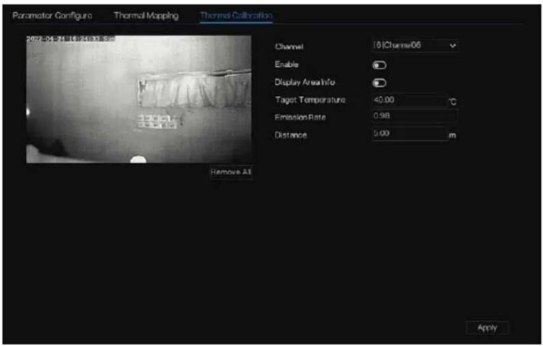
Table 7-6 Thermal calibration
| Parameter | Description | Setting |
| Display area information | Enable to show the information of displaying area. | [Setting method] enable |
| Target temperature | The special calibration tool's temperature, it is general black body's target temperature. | [Setting method] Input value |
| Emission rate | Emission rate is the thermal calibration device's base parameter, the general blackbody's is 0.98. | [Setting method]Input value |
| Distance | Distance is the actual horizontal distance between measuring object and the camera | [Setting method]Input value |
----End
7.1.9 Smart (Only for Some Models)

NOTE
It is only available for cameras with AI function.
The comparison function is only for AI multiobject cameras, please refer to actual cameras.
7.1.9.1 AI Multiobject
Figure 7-19 AI multiobject
![System Channel Record Alarm Network System AI Multiobject License Plate Recognition 2015-04-26 18:27:02 Channel [3]Channel03 Remove All Parameter Configure Schedule Face Detection Fullbody Detection Vehicle Detection Display Trace Info OFF Show Detection Area Confidence Degree Medium Image Matting Q…](/content/2026/05/1015136/images/de565beda19fcf5455cb6c0388c73184398b1703d0bbdb2381466c76e3c1ab00.jpg)
Table 7-7 AI multiobject
| Parameter | Description | How to set |
| Face detection | The camera will snap the face when someone appears in live video. | Enable |
| Full body detection | The camera will snap the whole body when someone appears in live video. | Enable |
| Licence plate detection | The camera will snap the licence when the vehicle's licence appears in live video. | Enable |
| Vehicle detection | The camera will snap the licence when the vehicle appears in live video. | Enable |
| Display trace info | Enable the function and a trace frame will show at live video. Mode 1: Mode 1: Mode 2: Mode 2: | Choose from drop list. |
| Show detection area | Enable to set a detection area, and the frame will show at live video | Enable |
| Confidence | The range of snap image, there are three type, | Choose from drop- |
| coefficient | such as high, mid and low. The higher the confidence, the better the snap quality and the fewer snapshots. | down list. |
| Face pixel min(30-300) | 30-300 pixels, the smaller the pixel be set, the more face will be captured, but it may be mistaken. | Input a value ranges 30 to 300 |
| Body pixel min(30-300) | 30-300 pixels, the smaller the pixel be set, the more body will be captured, but it may be mistaken. | Input a value range 30 to 300 |
| Vehicle pixel min(30-800) | 30-300 pixels, the smaller the pixel be set, the more face will be captured, but it may be mistaken. | Input a value range 30 to 800 |
| Image matting quality | The quality of snap images, There are three modes can be chosen, such as low, mid and high. | Choose from drop list. |
| Snapshot mode | There are three modes can be chosen, such as timing, and optimal. | Choose from drop list. |
| Upload image interval(1-10 s) | At timing mode, set the interval of upload image. | Input a value ranges 1 to 10 |
| FTP upload image matting | Configuration > Network Service > FTP, set FTP related parameters, the captured picture will be sent to the set FTP location | Enable |
| FTP upload whole image | Capture a picture and send a whole image. | Enable |
Figure 7-20 Schedule
![Al Multinobject License Plate Recognition 2023-04-24 18:51:16:00 Channel [3]Channel03 Remove All Parameter Configure Schedule All 2 4 6 8 10 12 14 16 18 20 22 24 Sun Mon Tue Wed Thu Fri Sat Apply](/content/2026/05/1015136/images/9bfc0b11bb60a2e3b17ba50dfd211fcd8187f6f665628aa2f930ff37745fa3a5.jpg)
----End
7.1.9.2 License Plate Recognition
Figure 7-21 License plate recognition

Table 7-8 License plate recognition
| Function | Procedure | Description |
| Licence plate recognition | The camera will snap the face when someone appears in live video. | Enable |
| Confidence coefficient | The range of snap image, there are three type, such as high, mid and low. The higher the confidence, the better the snap quality and the fewer snapshots. | Choose from drop-down list. |
| Minimum plate width (60-100 Pixel) | 60-100 pixels, the smaller the pixel, the more plates will be captured, but it may be wrong. | Input a value ranges 60 to 100 |
| Image matting quality | The quality of snap image, There are three modes can be chosen, such as low, mid and high. | Choose from drop-down list. |
| Snapshot mode | There are three modes can be chosen, such as timing, and optimal. | Choose from drop-down list. |
| Upload image interval(1-10 s) | At timing mode, set the interval of upload image. | Input a value ranges 1 to 10 |
| Snapshot count (1) | At optimal mode, set the number of snapshot image | Input 1 |
| FTP upload image matting | Configuration > Network Service > FTP, set FTP related parameters, the captured picture will be sent to the set FTP location | Enable |
| FTP upload whole image | Capture a picture and send a whole image. | Enable |
----End
7.1.10 Intelligent Tracking (Only for Some Models)

NOTE
This function is available for high speed camera.
The automatic target tracking function is that the dome camera can continuously track the moving target of the pre-made scene, and automatically adjusts the camera zoom focus according
to the moving target distance, and the dome automatically returns to the preset scene when the moving target disappears.
Figure 7-22 Intelligent tracking
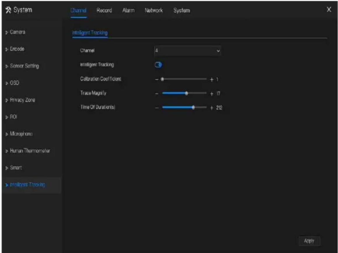
Table 7-9 Intelligent tracking parameters
| Parameter | Description | Setting |
| Enable | Enable the button to enable the intelligent tracking | [How to set]Click Enable to enable.[Default value]OFF |
| Calibration Coefficient | It is equivalent to a control coefficient, and real-time tracking doubling rate nonlinear positive correlation, usually the higher the installation height, the greater the calibration coefficient value; it ranges from 1 to 30 | [Setting method]Drag the slider.[Default value]1 |
| Trace Magnify | It is the value of lens zoom, it has a large influence on the real-time tracking magnification, | [Setting method]Drag the slider.[Default value]7 |
| Time of Duration | The maximum time of a tracking period, it ranges from 0 to 300 s. | [Setting method]Drag the slider.[Default value]120 |
----End
7.2 Record Setting
Set the Record Schedule, Disk, Storage Mode, S.M.A.R.T, Disk Detection, Disk Calculation, FTP and so on.
7.2.1 Record Schedule
Operation Description
Click Record in the main menu or click the record page of any function screen in the main menu to access the record schedule screen, as shown in Figure 7-23.
Figure 7-23 Record management screen
![System Channel Record Alarm Network System Record Schedule Record Schedule Channel [1]Channel01 Enable Record Enable Record Audio Enable ANR All 2 4 6 8 10 12 14 16 18 20 22 24 Sun Continuous Mon Alarm Tue Motion Wed I/O Thu MI/I/O Fri M & I/O Sat](/content/2026/05/1015136/images/9d446960357a3f0a9f77cba14c53978fd317c2bab2e7bcdc3522dcf095017fbe.jpg)
Operation Steps
Step 1 Select a channel from the drop-down list of channel option.
Step 2 Enable the record.
Step 3 Enable the record audio.
Step 4 Enable ANR, the camera is installed with SD card, if the camera is disconnected from the network, when the network is recovered, the NVR can read the recording of camera and copy the loss video form the SD card.
Step 5 Set the record schedule.
Method 1: Hold down the left mouse button, drag and release mouse to select the arming time within 00:00-24:00 from Monday to Sunday.

NOTE
- When you select time by dragging the cursor, the cursor cannot move out of the time area. Otherwise, no time would be selected.
● The selected area is blue. The default is all week. - Users can choose alarm type to record, if the chosen alarm is happening at the setting time, it will record. So that it will using the disk effectively to avoid repeating useless recording.
● The ANR function can be used only for the cameras with supplementary recording function. - Users can set different alarms to record.
Method 2: Click in the record schedule page to select the whole day or whole week.
Step 6 Deleting record schedule: Click again or inverse selection to delete the selected record schedule.
Step 7 Click Copy and select channels or tick all, then click OK to apply the record management settings to selected channels, click Apply Settings.
----End
7.2.2 Disk
View the total capacity of disk, disk status, disk SN code and storage space of disk. You can format the disk and set record expiration time.
Operation Description
Step 1 Click Record in the main menu or menu of the record screen and choose Disk to access the disk screen, as shown in Figure 7-24.
Figure 7-24 Disk screen
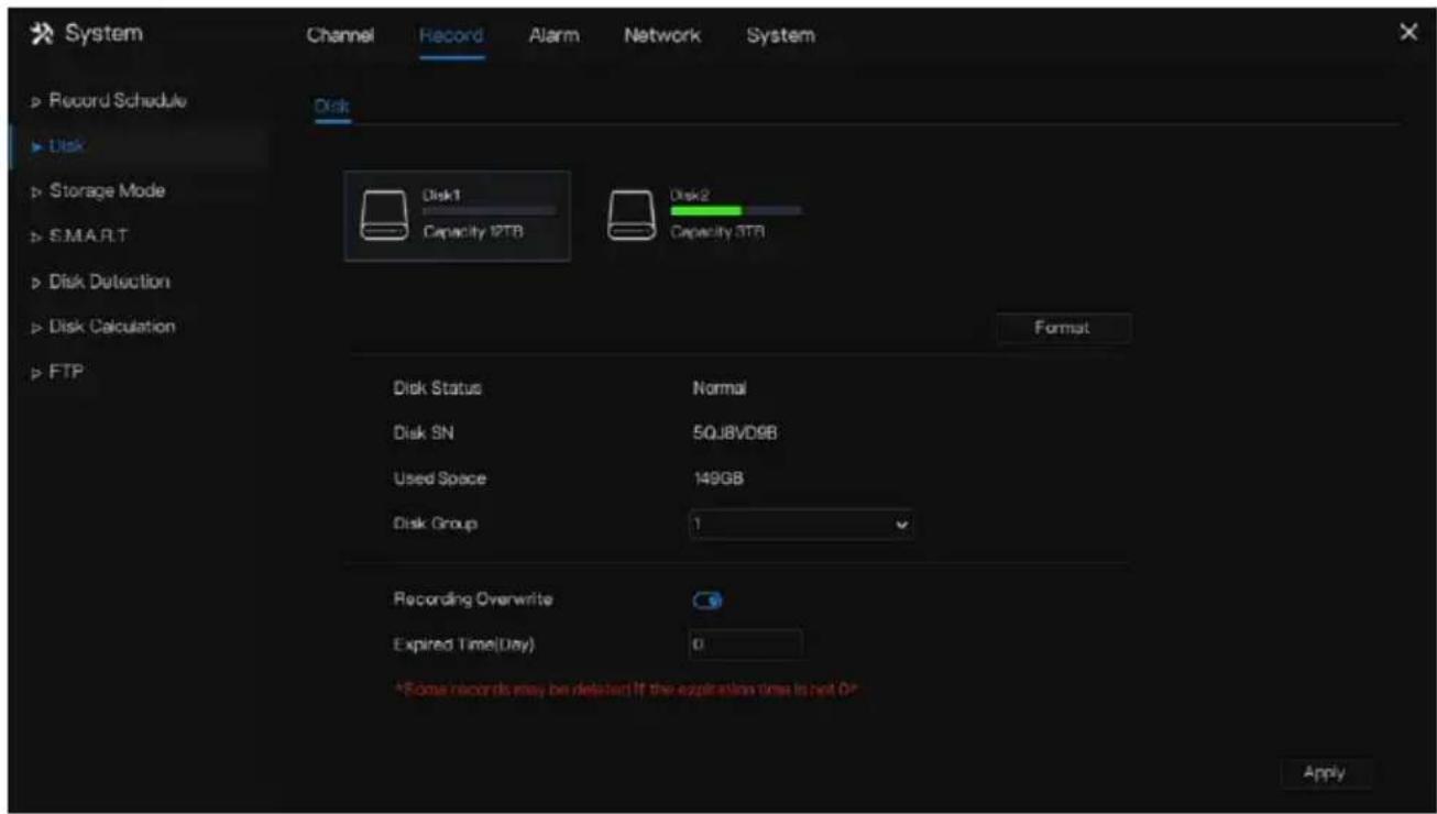
Step 2 Click Format. The message “Are you sure to format disk? Your data will be lost” is displaying.
Step 3 Choose the disk group, there are four groups.
Step 4 Click , and the disk would be formatted.
Step 5 Enable recording overwrite, the disk will be overwrote automatically.
Step 6 Record expiration setting. Select record expiration days from the drop-down list of record expiration. The expired time is not 0, the records will be deleted when the time is over the setting value.
Step 7 Click Apoly e settings.

NOTE
The disk groups can keep the recording of channels at different disks, it will improve the storage efficiency.
The expired time is 0, it means the disk will be rewrite only when the disk is full.
----End
7.2.3 RAID (Only for Some Models)
The NVR support to build/edit/delete the RAID. Users can choose the type of RAID according to the importance of recording.

NOTE
RAID is only used for the device with 4 disks or more. And the disks must be enterprise level disks. The capacity of disks is the same for efficient using.
The maximum capacity of RAID cannot exceed 100T.
RAID5 at least 3 disks can be created. RAID6 at least 4 disks can be created. RAID10 at least 4 disks can be created. Create hot spare disk need more one disk or double basic disks.
The capacity of disks is the same for efficient using
Figure 7-25 RAID

Operation Steps
Step 1 Click RAID to create the RAID.
Step 2 Click Create to choose a disk to create a new RAID.
Step 3 Tick Hot-spare Disk to back up in case the disk is broken. The number of disk must be more than one.
Step 4 Click to save the creation, format the new RAID.
----End
7.2.4 Storage Mode
Users need to distribute the channels to different disk groups, and use disk capacity reasonably, as shown in Figure 7-26
Figure 7-26 Storage mode

Operation Steps
Step 1 Choose the disk group.
Step 2 Select the channel to record to disk group.
Step 3 Click Apply to save the settings.
Step 4 The group list will show the detail information.

NOTE
If the channels are not in list, it means NVR will not record these channels, please make sure that all channels are in list.
Choose number of channel number you should consider the capacity of disk group.
----End
7.2.5 S.M.A.R.T
7.2.5.1 S.M.A.R.T
S.M.A.R.T is Self-Monitoring Analysis and Reporting Technology, u which is able to check the disk as shown in Figure 7-27.
Figure 7-27 S.M.A.R.T

----End
7.2.5.2 WDDA
The western digital disk has the WDDA function, the NVR can read the information of disk, so that users can view the status of disk, as shown in Figure 7-28.
Figure 7-28 WDDA

----End
7.2.6 Disk Detection
Detect the disk before recording videos so that the data are secure as shown in Figure 7-29.
Figure 7-29 Disk Detection

Operation Steps
Step 1 Choose the disk from the drop-down list.
Step 2 Tick All or key Area to detect the disk. It will take some several minutes.
Step 3 Click Scan to scan the disk.
Step 4 The result of disk will show in interface

NOTE
The green block means good, the red block means bad, if the red blocks are too much or at key section, please change the disk immediately.
Please turn off the video recording before the disk is detected, otherwise the recording of video maybe lost.
----End
7.2.7 Cloud Storage (Only for Some Models)
The cloud storage can save the motion detection and intelligent analysis alarm Support Google Drive.
Figure 7-30 Cloud Storage
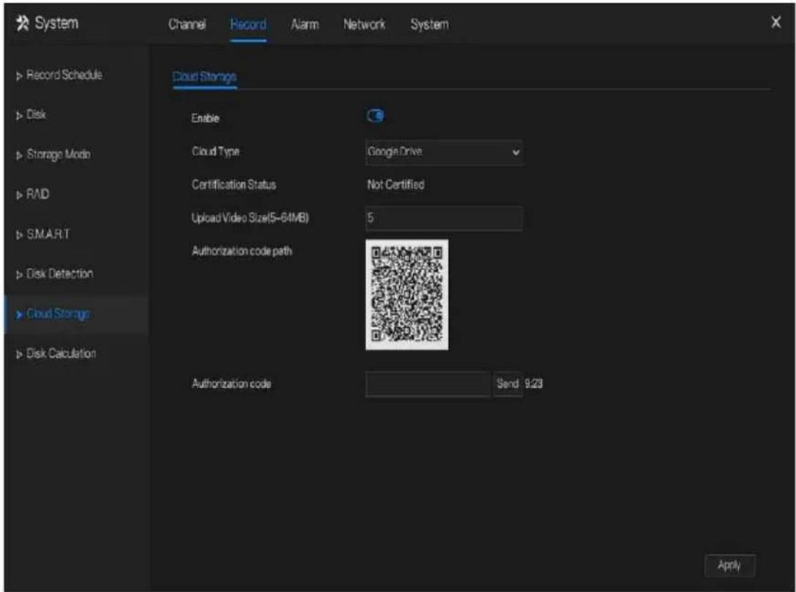
Operation Steps
Step 1 Enable the cloud storage, and the UUID of code path will show.
Step 2 Choose the cloud type, the default is Google cloud.
Step 3 Set upload video size, the video is saving in sub stream(the video size is less).
Step 4 Use browser to scan the UUID to jump to Google drive certification, input the account and password to certificate the NVR.
Step 5 Input the code, click Send to fish certificate, as shown in Figure 7-31.
Figure 7-31 Certification

Step 6 Click Apply to save the settings

NOTE
Google Cloud only needs to be authenticated once, without multiple authentications. After the authentication is completed, the cloud storage function can be turned on or off as required.
This function needs to be re-certified after the device is restored to factory settings.
The UUID is the path of Google drive.
----End
7.2.8 Disk Calculation
Users can calculate the usage of disk, so that he can set the storage strategy reasonably, as shown in Figure 7-32.
There are two modes can be set, computing capacity and computing time
Figure 7-32 Disk calculation of capacity

Figure 7-33 Disk calculation of time

----End
7.2.9 FTP
Enable FTP upload, when the alarm happens, users can linkage the FTP upload to save the alarm recordings.
Figure 7-34 FTP

Step 1 Enable the FTP upload.
Step 2 Input the FTP address and port.
Step 3 Input the account, password and FTP path.
Step 4 Set the upload file size, it ranges from 0 to 64 MB.
Step 5 Click "Test" to test the parameters. After the test is successful, click "Apply" to save the settings
----End
7.3 Alarm Management
Set the General alarm information, Motion Detection, Video Loss, Intelligent Analysis, Alarm In, Abnormal Alarm, Alarm out and Local intelligent analysis in alarm management screen.
7.3.1 General
7.3.1.1 General
Step 1 Click Alarm in the main menu (or click the alarm page of any function screen in the main menu) to access the alarm management screen, as shown in Figure 7-35.
Figure 7-35 Alarm management screen

Step 2 Click to enable the alarm function.
Step 3 Select a value from the drop-down list of duration time.
Step 4 Click Apply to save alarm settings.
----End
7.3.1.2 IO control push
If you select normally open and tick the disabled items, the alarm input 1 will not push message.
Only when the alarm in 1 is in the normally closed, it can push alarm message.
Step 1 Enable the IO control push.
Figure 7-36 IO control push
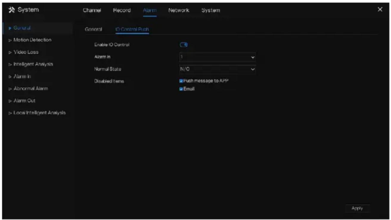
Step 2 Choose one alarm in and mode(N/C, N/O).
Step 3 Tick the disable items, click “Apply” to save settings.
----End
7.3.2 Motion Detection
The NVR will send motion detection alarm while something moving in the specific view of camera.
Operation Description
Step 1 Click Motion Detection in the main menu or menu of the alarm management screen and choose Motion Detection to access the Motion Detection screen, as shown in Figure 7-37.
Figure 7-37 Motion detection screen
![System Channel Record Alarm Network System General Motion Detection Channel [1]Channel01 Video Loss Enable Motion Detection Enable Motion Analysis Event Actions [+]Detraction Area Schedule Push message to APP Pop up message to monitor Email Runner FTP PTZ Full Screen Enable Alarm Out Enable Camera A…](/content/2026/05/1015136/images/483f2f3c723497070fdc6d6b9ebf9e03dbe20dcf100fe28056bfcdf2193a4073.jpg)
Operation Steps
Step 1 Select a channel from the drop-down list of channel.
Step 2 Click 📄 enable motion detection.
Step 3 Enable motion analysis if the camera detects the motion action, the area will be block as shown in Figure 7-38.
Step 4 Enable the Event actions include: push messages to App, pop up messages to monitor, send Email, buzzer, FTP, PTZ, full screen, alarm out, camera alarm out, event recordings and so on.
Step 5 Click Area page to access the motion detection area setting, as shown in Figure 7-38.
Figure 7-38 Motion detection area setting screen
![Motion Detection Channel [1]Channel01 Enable Motion Detection Enable Motion Analysis Event Actions Detection Area Schedule 02-04-24 18:52:28 Sat Sensitivity Medium Copy Apply](/content/2026/05/1015136/images/cadf7c43da1dfc4fe9169b75aa85ac83cb5b5cb8f2984277d3136abe5be0c8a3.jpg)
Area :
- Hold down and drag the left mouse button to draw a motion detection area.
- Select a value from the drop-down list next to Sensitivity.
Step 6 Click Schedule page to access the schedule screen. For details, please see 7.2.1 Record Schedule Figure 7-23Step 5 Set the record schedule.
Step 7 Click Copy and select channels or tick all, then click OK to apply the motion detection settings to cameras in selected channels, click Apply motion detection alarm settings.

NOTE
Double click to delete the selected area.
The default area is whole area.
If you leave the page without applying, the tip "Do you want to save?" would show. Click save to save the settings. Click cancel to quit the settings.
Enable the alarm out, users need to set alarm time and output ID, four ID are corresponding to back panel's alarm out, 1 A and 1 B, 2 A and 2 B, 3 A and 3 B, 4 A and 4 B.
Channel alarm out is corresponding to alarm port of camera.
Figure 7-39 Alarm schedule

----End
7.3.3 Video Loss
If a camera is disconnected to NVR, it will trigger video loss alarm.
Operation Description
Click Video Loss in the main menu or menu of the alarm management screen and choose video Loss to access the video loss screen, as shown in Figure 7-40.
Figure 7-40 Video loss screen
![System General Motion Detection Video Loss Intelligent Analysis Alarm In Abnormal Alarm Alarm Out Local Intelligent Analysis Channel Record Alarm Network System Virion Lops Channel [1]Channel01 Enable Video Lops Alarm Event Actions Schedule Push message to APP Pop up message to monitor Email Buzzer…](/content/2026/05/1015136/images/106991df3bf9c43fcc7ede26ab5228105e30d50c93a60c80fc8017271c42a8ff.jpg)
Operation Steps
Step 1 Select a channel from the drop-down list of channel.
Step 2 Click to enable video loss alarm.
Step 3 Enable the Event actions include: push message to App, pop up message to monitor, send Email, buzzer, FTP, PTZ, alarm out, event recording and so on.
Step 4 Click Schedule page to access the schedule screen.
Step 5 For details, please see 7.2.1 Record Schedule Figure 7-23Step 5 Set the record schedule.
Step 6 Click Copy a channel, then click to apply the OK parameter settings to cameras in selected channels, click Apply video loss settings.
----End
7.3.4 Intelligent Analysis (Only for Some Models)

NOTE
The channel camera can set the intelligent analysis which are depended on the performance of cameras.
Operation Description
Step 1 Click Intelligent Analysis in the main menu or menu of the alarm management screen and choose Intelligent Analysis to access intelligent analysis screen, as shown in Figure 7-41.
Figure 7-41 Intelligent Analysis screen
![System Channel Record Alarm Network System General Inflation Line Crossing Double Virtual Fences Object Left Object Removed Signal Back Loiter Motion Detection Channel [3]Channel00 Video Loss Enable Intelligent Analysis Event Action Detection Area Schedule Abnormal Alarm Push message to APP Pop up m…](/content/2026/05/1015136/images/1eff383a31299b21fb5877ff5c9c3ad9561e1e0bae52dfeec33b356776c80b19.jpg)
Step 2 Select one action to set the alarm.(Intrusion, Line crossing, Single virtual fence, Double virtual fences, Object left, Object removed, Signal bad, Loiter, Multi loiter, Abnormal speed, Converse, Illegal parking, Personnel count, Fence, Enter area, Leave area, Advanced).
Step 3 Select a channel from the drop-down list of channel.
Step 4 Click to enable intelligent analysis alarm.
Step 5 Enable the event actions include: push message to App, pop up message to monitor, send Email, buzzer, FTP, PTZ, full screen, alarm out, camera alarm out, event recording and so on.
Step 6 Click Schedule page to access the schedule screen.
Step 7 For details, please see Figure 7-23Step 5 Set the record schedule.
Step 8 Click Copy a channel, then click to apply the OK parameter settings to cameras in selected channels, click Apply video loss settings.
Figure 7-42 Personnel count
![System Channel Record Alarm Network System General Multi Loiter Abnormal Speed Converse Illegal Parking Personnel Course Fence Enter Area Leave Area Motion Detection Channel [3]Channel03 Video Loss Enable Intelligent Analysis Event Actions Detection Area Schedule Alarm In Abnormal Alarm Alarm Out Lo…](/content/2026/05/1015136/images/32a0a717cf0dc1bc4a7009e8b0dd7aca340b606e96f0aba12c735a378d97e3df.jpg)
Table 7-10 Personnel count parameters
| Parameter | Description | Setting |
| Enable | Click the button to enable personnel count. | [How to set]Click Enable to enable.[Default value]OFF |
| OSD enable | Enable, the statistical data of personnel count will show on OSD | [How to set]Click Enable to enable.[Default value]OFF |
| Counting clear interval | There are five modes can be chosen, such as 10 min, half-hour, 1 hour, 12-hour, 1 day. | [Setting method]Choose from drop-down list[Default value]7 |
| Area type | The area to distinguish entry and exit. | [Default value]Line |
----End
Fence:
It is only available for fence AI multi-object cameras. When a person or car is found in detection area, it will alarm.
Users can choose several event actions to alarm.
Figure 7-43 Fence
![System Channel Record Alarm Network System General Multi Order Abnormal Speed Converse Bagd Parking Personnel Count Fence Enter Area I have Area Motion Detection Channel [1]Channel01 Video Loss Enable Intelligent Analysis Event Actions Detection Area Schedule Alarm In Abnormal Alarm Push message to…](/content/2026/05/1015136/images/68f51926c3649b865dbaaa718101fefaa0cd730c828e6a917d8ec1a988ed387c.jpg)
Figure 7-44 Fence detection area
![System Channel Record Alarm Network System General Multi Loiter Abnormal Speed Converse Illegal Parking Personnel Count Force Enter Area Leave Area Motion Detection Channel [1]Channel01 Video Loss Enable Intelligent Analysis Event Actions Detection Area Schedule Abnormal Alarm 2022-04-25 11:04:40 Ma…](/content/2026/05/1015136/images/dc445288a6567660effa6bf82aff0cd879c08ea6d1683c7b09e04eb35929f759.jpg)
Enable limit target type, choose the type(person or car, person, car).
Enable video stream draw line, when detects the car or person, it will show the blue frame to mark the target.
Use the mouse to draw the detection area, users can draw serval areas depending on the real condition.
----End
7.3.5 Alarm In

NOTE
This function requires access to a camera that supports external alarm in.
There are two types alarm in, one is the NVR's alarm in, another is the camera channel's alarm in.
Operation Description
Click Alarm in in the main menu or menu of the alarm management screen and choose Alarm in to access the alarm in screen, as shown in Figure 7-45.
Figure 7-45 Alarm in screen
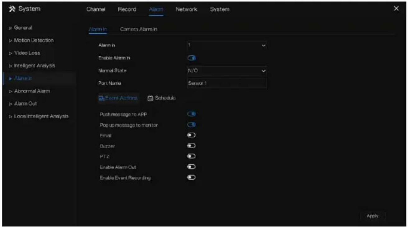
Figure 7-46 Camera alarm in
![System Channel Record Alarm Network System General Motion Detection Video Loss Intelligent Analysis Alarm In Abnormal Alarm Alarm Out Local Intelligent Analysis Alarm In Camera Alarm In Channel [1]Channel01 Alarm In 1 Normal State N/O Enable Alarm In Event Actions Schedule Push message to APP Pop up…](/content/2026/05/1015136/images/da92a85077eca0861ba20e5c62e4cc047b2eaef5ad374431b7a6eb62856cdfd1.jpg)
Operation Steps
Step 1 Select a channel in alarm in.
Step 2 Click to enable or disable the functions.
Step 3 Select Alarm type from the drop-down list.

NOTE
NC: Normal close the alarm
NO: Normal open the alarm
Step 4 Set name.
Step 5 Enable the event actions include: push message to App, pop up message to monitor, send Email, buzzer, FTP, PTZ, full screen, alarm out, camera alarm out, event recording and so on.
Step 6 Click Schedule page to access the schedule screen. For details, please see 7.2.1 Record Schedule Figure 7-23Step 5 Set the record schedule.
Step 7 Click Apply Settings of Alarm in.
----End
7.3.6 Abnormal Alarm
Abnormal alarm includes disk alarm, IP conflict and network disconnected.
Operation Description
Step 1 Click Abnormal Alarm in the main menu or menu of the alarm management screen and choose Abnormal Alarm to access the abnormal alarm screen, as shown in Figure 7-47.
Figure 7-47 Abnormal alarm screen
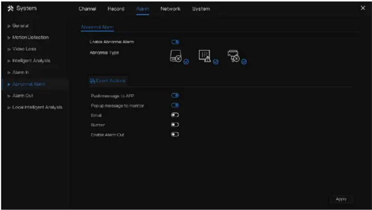
Step 2 Tick the abnormal actions.
Step 3 Enable the event actions include: push message to App, pop up message to monitor, send Email, buzzer, alarm out and so on.
Step 4 Click Apply to save abnormal alarm settings.
----End
7.3.7 Alarm Out
7.3.7.1 Alarm Out
Choose one output ID as the output interface.
Figure 7-48 Alarm out

----End
7.3.7.2 Camera Alarm out

NOTE
This function requires access to a camera that connected to an external alarm out device.
Figure 7-49 Camera alarm out
![System Channel Record Alarm Network System ► Gunural ► Motion Detection ► Video Loss ► Intelligent Analysis ► Alarm In ► Abnormal Alarm ► Alarm Out ► Local Intelligent Analysis Alarm Out Camera Alarm Out Channel [1]Channel01 Port Number 1 Port Name Name Valid Signal Close Alarm Output Mode SwitchMod…](/content/2026/05/1015136/images/8c8596a5efbf562145e48263c54ecf7b882749c711671cfbb5da30437be88ffe.jpg)
Table 7-11 Camera alarm out
| Parameter | Description | Setting |
| Alarm Output | ID of the alarm output channel. NOTE The number of alarm output channels depends on the device model. | [Setting method] Select a value from the drop-down list box. [Default value] 1 |
| Name | Alarm output channel name. | [Value range] 0 to 32 bytes |
| Valid Signal | The options are as follows: • Close: An alarm is generated when an external alarm signal is received. • Open: An alarm is generated when no external alarm signal is received. | [Setting method] Select a value from the drop-down list box. [Default value] Close |
| Alarm Output Mode | When the device receives I/O alarm signals, it will send the alarm information to an external alarm device in the mode specified by this parameter. The options include the switch mode and pulse mode.NOTEIf the switch mode is used, the alarm frequency of the device must be the same as that of the external alarm device.If the pulse mode is used, the alarm frequency of the external alarm device can be configured. | [Setting method]Select a value from the drop-down list box.[Default value]Switch Mode |
| Alarm Time(ms)(0: Continuous) | Alarm output duration. The value 0 indicates that the alarm remains continuous valid. | [Setting method]Enter a value manually.[Default value]0[Value range]0 to 86400 seconds |
| Manual Control | Control the alarm output. | N/A |
----End
7.3.8 Local Intelligent Analysis
7.3.8.1 General
At “Alarm > Local Intelligent Analysis > General” interface, enable the local intelligent analysis to set the local intrusion, as shown in Figure 7-50.
Figure 7-50 Local intelligent analysis – General

Enable the alarm function.
Enable Draw Rectangle, the detection rectangle will be showed on the live video of intrusion.
Choose the channels, up to 4 channels can be chosen.
Enable or disable the intrusion, modify the channels, the device will be rebooted.
7.3.8.2 Intrusion
At “Alarm > Local Intelligent Analysis > Intrusion” interface to set the parameter of local intrusion.
The intrusion refers to that an alarm is generated when the targets of specified types (such as person, car, and both person and car) enter the detection area.
Figure 7-51 Intrusion
![System Channel Record Alarm Network System General Influsive Motion Detection Channel [1]Channel01 Video Loss Enable Intelligent Analysis Event Actions Detection Area Schedule Alarm In Abnormal Alarm Push message to APP Alarm Out Pop up message to monitor Local Intelligent Analysis Email Bluzzer FTP…](/content/2026/05/1015136/images/557ae19d97c8be502187d7d6381c93824c8cdf6aefb22f385e2c4a698d45e002.jpg)
Event action:
Choose the channel to enable the intrusion, enable the event actions (such as push message to App, Pop up message to monitor, Email, Buzzer, FTP, PTZ, Full screen, Alarm out, Camera alarm out, Event recording, and so on). Click “Apply” to save the settings.
Figure 7-52 Detection area
![General Inflation Channel [1]Channel01 Enable Event Actions Detection Area Schedule 2022-04-26 11:43:21 kgs Limit Target Type Type Person Remove All Apply](/content/2026/05/1015136/images/4bfce44a359eedbf5a85a9d936d74f1cc94a1bb1a89bf853dbb4aea10e654c4c.jpg)
Detection area:
Move the cursor to the drawing interface and click to generate a point, move the cursor to draw a line, and then click to generate another point. This is how a line is generated. In this way, continue to draw lines to form any shape, and right-click to finish line drawing.

NOTE
- A drawn line cannot cross another one, or the line drawing fails.
- Any shape with 8 sides at most can be drawn.
- The quantity of detection areas is not limited yet and will be described in future when a limit is applied.
Choose Limit target from the drop-down list, person/ person or car / car.
Figure 7-53 Set schedule
![General Channel [1]Channel01 Enable Event Actions Detection Area Schedule All 2 4 6 8 10 12 14 16 18 20 22 24 Sun Mon Tue Wed Thu Fri Sat Apply](/content/2026/05/1015136/images/2a33396bcd3500aee69a5e45d83f6671712aaec05e761b712c5b42f9434ee609.jpg)
Set schedule:
Method 1: Click left mouse button to select any time point within 0:00-24:00 from Monday to Sunday as shown in Figure 7-53.
Method 2: Hold down the left mouse button, drag and release mouse to select the schedule within 0:00a-24:00 from Monday to Sunday.

NOTE
When you select time by dragging the cursor, the cursor cannot be moved out of the time area. Otherwise, no time can be selected.
Method 3: Click in the schedule page to select the whole day or whole week.
Deleting schedule: Click 📄 again or inverse selection to delete the selected schedule.
----End
7.4 Network Management
Set the Network Parameter, 802.1X, DDNS, E-mail, Port Mapping, P2P, IP Filter, SNMP 3G/4G and PPPOE, Network Traffic in the network management screen.
Operation Description
Step 1 Click Network in the main menu (or click the network page of any function screen in the main menu) to access the network management screen, as shown in Figure 7-54.
Figure 7-54 Network management screen

7.4.1 Network
Set DHCP and DNS manually or automatically.
7.4.1.1 IP
Operation Steps
Step 1 Click next to DHCP to enable or disable the function of automatically getting an IP address. The function is disabled by default.
Step 2 If the function is disabled, click input boxes next to IP, Subnet mask, and Gateway to set the parameters as required.
Step 3 Click next to Obtain DNS Automatically to enable or disable the function of automatically getting a DNS address. The function is enabled by default.
Step 4 If the function is disabled, click input boxes next to DNS 1(default 192.168.0.1) and DNS 2(default 8.8.8.8), delete original address, and enter a new address.
Step 5 Click Apply settings.
----End
7.4.1.2 Port
Operation Steps
Step 1 Click Port page to access the port setting screen, as shown in Figure 7-55.
Figure 7-55 Port setting screen
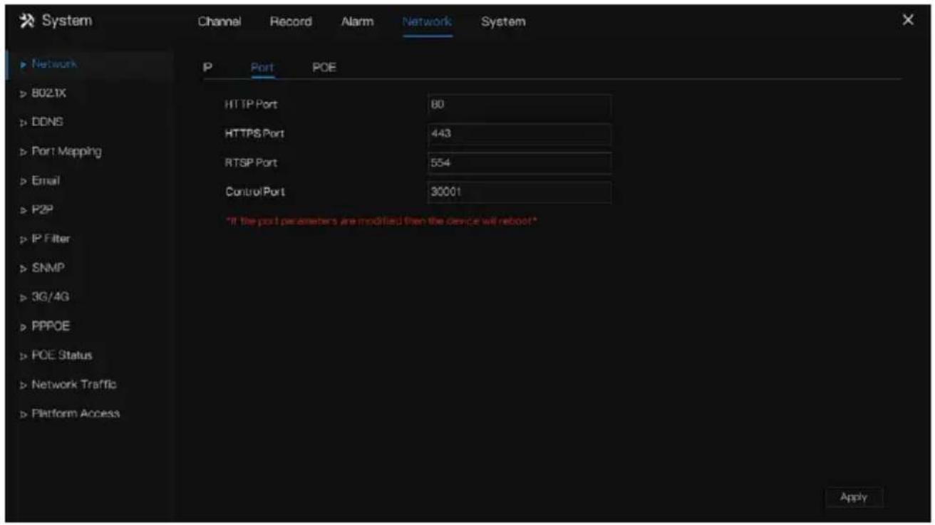
Step 2 Set the HTTP port, HTTPS port, RTSP port and Control port.
Step 3 Click Apply port settings.
----End
7.4.1.3 IPv4CCTV (Only for Some Models)
The no POE device has two LANs, LAN1 and LAN2.
Operation Steps
Step 1 Click IPv4 CCTV page to access the LAN2 setting screen, as shown in Figure 7-56.
Figure 7-56 IPv4 CCTV

Step 2 Input the IP address, subnet mask, default gateway.
Step 3 Click Apply to save the settings.

NOTE
LAN1 and LAN2 can be connected to different network, so that NVR can add more cameras. LAN1 usually is connected to the external network, it is default gateway. LAN2 connect to internal network.
----End
7.4.1.4 POE (Only for Some Models)
Operation Steps
Step 1 Click POE page to access the POE setting screen, as shown in Figure 7-57.
Figure 7-57 POE screen

Step 2 The NVR will deploy IP addresses to the cameras connected to POE immediately.
Step 3 Click Apply E camera IP address successfully.
----End
7.4.1.5 WiFi Parameter (Only for Some Models)
Operation Steps
Step 1 Click WiFi Parameter page to access the WiFi Parameter setting screen, as shown in Figure 7-57.
Figure 7-58 WiFi Parameter

Step 2 Set the parameters of WiFi.
Step 3 Click Apply to set OE camera IP address successfully.

NOTE
BSDID, default value of the device, cannot be changed.
SSID, the name can be changed to facilitate customer search.
WiFi channel; 1-13 channels, plus the other channel, can be changed according to network blocking conditions to avoid interference.
The area can be selected according to the country where it is located, MKK, ETSI1, ETSI2, FCC.
----End
7.4.1.6 WiFi Network (Only for Some Models)
Operation Steps
Step 1 Click WiFi Parameter page to access the WiFi Parameter setting screen, as shown in Figure 7-57.
Figure 7-59 WiFi network

----End
7.4.2 802.1 X
Operation Steps
Step 1 Click next to 802.1 X to enable or disable the function .The default is disabled.
Figure 7-60 802.1 X

Step 2 Input the user and password of 802.1X, the account is created by user.
Step 3 Click Apply to save the settings. The visitor to view the NVR need to input account to certify.
----End
7.4.3 DDNS
Please make sure connect the specified camera to the Internet, and obtain the user name and password for logging into the dynamic domain name system (DDNS) from the server.
Operation Steps
Step 1 Click DDNS in the main menu or menu of the network management screen and choose DDNS to access the DDNS screen.
Step 2 Click next to Enable to enable the DDNS function. It is disabled by default, as shown in Figure 7-61.
Figure 7-61 DDNS setting screen

Step 3 Select a required value from the protocol drop-down list.
Step 4 Set domain name, input user and password.
Step 5 Click Test to block the domain name.
Step 6 Click Apply DNS network settings

NOTE
An external network can access the NVR via an address that is set in the DDNS settings.
----End
7.4.4 Port Mapping
Step 1 Click Port Mapping in the main menu or menu of the network management screen and choose Port Mapping to access the port mapping screen, as shown in Figure 7-62.
Figure 7-62 Port mapping setting screen
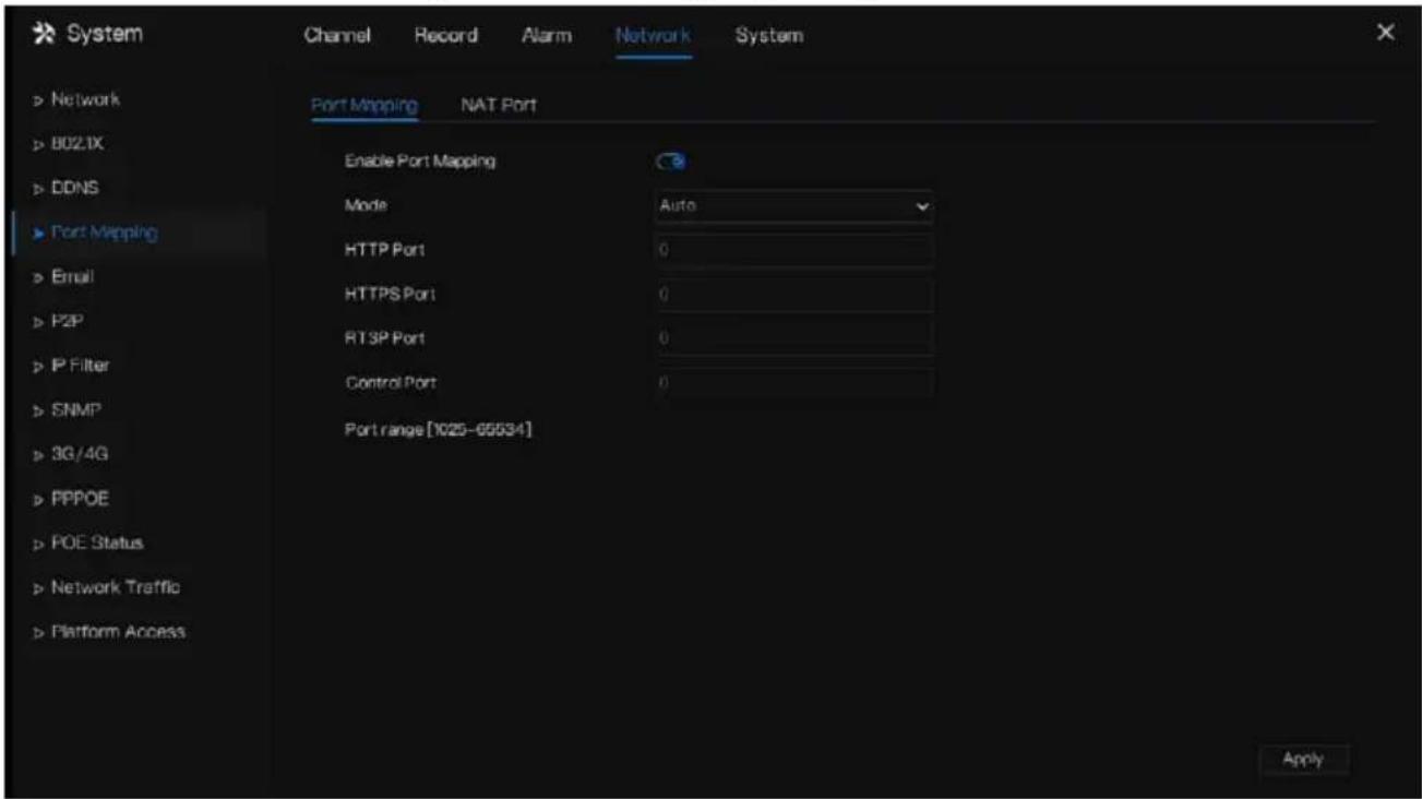
Step 2 Select UPnP enable type.
Step 3 Manual UPnP: input http port, data port and client port manually.
Step 4 Auto UPnP: device obtain the port automatically.
Step 5 Click Apply Settings.
----End
7.4.4.2 NAT Port
NAT Port (Network Address Translation). Access the NVR channels through the NAT port. Users can set the start port, and it will generate the end port automatically. We will view the NAT port when we access the channel through clicking 4.8... at Web interface.
Figure 7-63 NAT port
![System Channel Record Alarm Network System ► Network ► 8021X ► DDNS ► Port Mapping ► Email ► P2P ► IP Filter ► SNMP ► 3G/4G ► PPPOE ► POE Status ► Network Traffic ► Platform Access Port Mapping NAT Port Start Port 40001 End Port 40040 Port range [40001-65534] Apply](/content/2026/05/1015136/images/dcea58a0da19ceb65cce619c225512efdbbcc4283116f601b3b9fdaabfbc31d8.jpg)
---End
7.4.5 Email
If the simple mail transfer protocol (SMTP) function is enabled, the device automatically sends alarm information to specified email addresses when an alarm is generated. Two mailboxes can be set as receivers.
Operation Steps
Step 1 Click E-mail in the main menu or menu of the network management screen and choose E-mail to access the E-mail screen, as shown in Figure 7-64.
Figure 7-64 E-mail setting screen

Figure 7-65 E-mail server 2

Step 2 Set SMTP server address and SMTP server port manually.
Step 3 Input E-mail sender, user name and password manually.
Step 4 Set E-mail for receiving alarm. the message “Mail has been sent, please check” is displaying. Open the mail, if the verification code is received, that shows the E-mail is set successfully.
Step 5 Set E-mail for retrieve the password. the message “Mail has been sent, please check” is displaying. Open the mail, if the verification code is received, E-mail is set successfully.
Step 6 Set SSL encryption for encrypting mail or not, set sending interval.
Step 7 Click Apply Settings.
----End
7.4.6 P2P
Show the UUID code and set the P2P status of the device.
Operation Steps
Step 1 Click P2P in the main menu or menu of the network management screen and choose P2P to access the P2P screen, as shown in Figure 7-66.
Figure 7-66 P2P screen

Step 2 Click ☐ be enable the P2P function.
Step 3 Click Apply to save P2P network settings or click Cancel to cancel settings.
Step 4 After the Inview Pro4 is installed in mobile phone, run the APP and scan the QR to add and access the NVR when the device is online.
----End
7.4.7 IP Filter
Set the IP address in specified network segment to allow or prohibit access.
Operation Steps
Step 1 Click IP Filter in the main menu or menu of the network management screen and choose IP Filter to access the IP filter screen, as shown in Figure 7-67.
Figure 7-67 IP Filter setting screen

Step 2 Click next to IP Filter to enable the function of IP Filter.
Step 3 Select black list or white list drop-down list.
Step 4 Click + to set black &white list IP segment screen is displaying, as show in Figure 7-68.
Figure 7-68 IP Address Segment screen

Step 5 Enter value manually for start IP address, end IP address.
Step 6 Click OK. The system saves the settings. The black and white lists IP segment listed in the black (white) list.

NOTE
Black list: A list of IP addresses in specified network segment that are regarded as unacceptable or untrustworthy and should be excluded or avoided.
White list: a list of addresses in specified network segment considered to be acceptable or trustworthy.
Select a name in the list and click Delete to delete the name from the list.
Select a name in the list and click Edit to edit the name in the list.
Only one rule type is available, and the last rule type set is efficient.
----End
7.4.8 SNMP
There are three versions of simple network management protocols at interface.
Operation Steps
Step 1 Click IP Filter in the main menu or menu of the network management screen and choose IP Filter to access the IP filter screen, as shown in Figure 7-69.
Figure 7-69 SNMP settings screen

Step 2 Click next to SNMPV 1 to enable the function. The interface is shown as Figure 7-70.
Figure 7-70 SNMPV 1/2 interface

Step 3 Input the parameters of protocol.
Step 4 Click Apply Settings or click to cancel Settings Cancel ----End
7.4.9 3G/4G
Users can connect NVR to the data network using a modem.
Operation Steps
Step 1 Plug the modem to NVR, and enable the 3G/4G function, as shown in Figure 7-71.
Figure 7-71 3G/4G setting screen

Step 2 If the connection is successful, set other parameters.
Step 3 Choose access mode, the default is AUTO. There are five modes can be chosen, such as AUTO, LTE, TD-SCDMA, WCDMA, GSM/GPRS.
Step 4 Input the APN, dial number, username, password, IP address. At auto mode, all these parameters can be obtained automatically.
Step 5 Click Apply Settings.

NOTE
Modify the access mode of 3G/4G (AUTO, LTE, TD-SCDMA, WCDMA, GSM/GPRS). If you cannot dial within 5 minutes, re-plug the modem.
Users are familiar with the relevant network (different service provider parameters are different) and modem information before manually switching to other modes, the recommended mode is Auto.
When using the 3G / 4G function, you need to manually close the PPPOE function. Only one function can be used at a time.
If the Internet access type is LTE (4G network), you do not need to dial the number, user name and password.
----End
7.4.10 PPPOE
PPPOE point to point protocol Ethernet, user use the PPPOE to access network immediately, as shown in Figure 7-72.
Figure 7-72 PPPOE
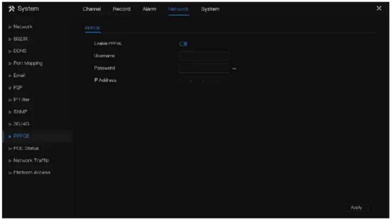
Step 1 Enable the PPPOE function.
Step 2 Input the username, password (provided by network operator).
Step 3 Click Apply Settings, and the IP is obtained automatically.
Step 4 Users input the IP to access NVR web immediately.
----End
7.4.11 POE Status (Only for Some Models)
Users can view the status of POE intuitively, as shown in Figure 7-73.
Figure 7-73 POE status
![graph LR A["POE Status"] --> B["Internet"] A --> C["Router"] B --> D["10W"] B --> E["0.0W"] B --> F["0.0W"] B --> G["0.0W"] B --> H["8.4W"] B --> I["0.0W"] B --> J["0.0W"] B --> K["0.0W"] C --> L["8.4W"] C --> M["0.0W"] C --> N["0.0W"] C --> O["0.0W"] C --> P["8.4W"] C --> Q["0.0W"] C --> R["0.0W"]…](/content/2026/05/1015136/images/b5e858de36142f2dd4ac9a634404f73a71d1a5fd49b04230a36d668d8cbadbb1.jpg)
----End
7.4.12 Network Traffic
Users can view the network traffic immediately, as shown in Figure 7-74
Figure 7-74 Network traffic
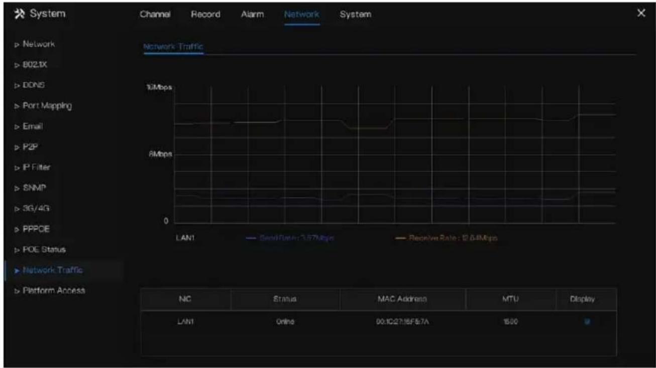
There are two rates, transmit rate and receive rate. The status of LAN(s) show on list.
----End
7.4.13 Platform Access
If the NVR and platform system are not at the same local network, ensure the NVR is connected to the same external server as the platform system. You should build a server for platform in advance, platform's remote IP/Port and NVR are mapping port to external network.
Step 1 Choose Configuration > Network Service > Platform Access.
The Platform Access page is displayed, as shown in Figure 7-75
Figure 7-75 Platform Access page
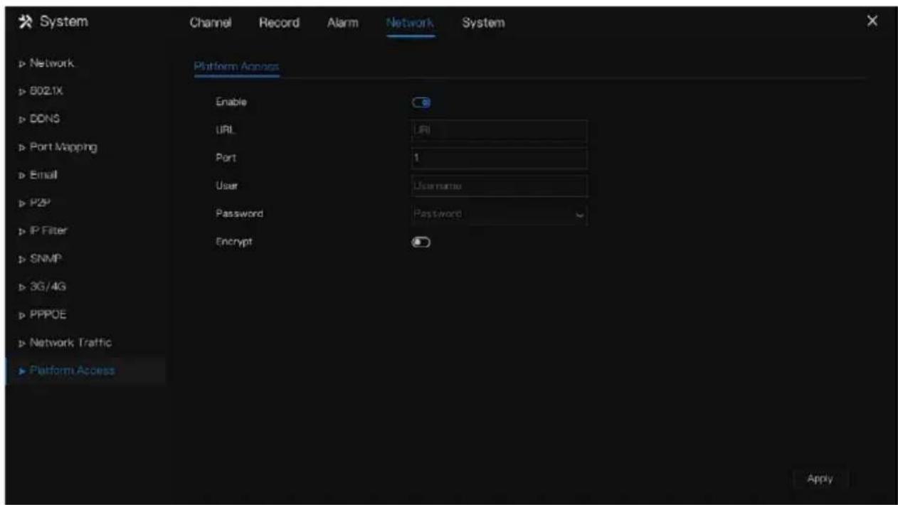
Step 2 Input the parameters. The URL and port are the platform server IP address and port Step 3 The name and port are the platform's login name and password.
Step 4 Add the NVR to platform, you should input the following information.
1: IP/ID/Domain name is Device ID of NVR.
Figure 7-76 IP/ID/Domain

2: The connection mode should be chosen Device active registration.
Figure 7-77 Connect NVR to platform

3: the CMU, MDU and IAU servers of platform should be mapped to the ports to external network in advance.
Figure 7-78 URL address / port

Step 5 If you want to encrypt the access, you can enable the Encrypt.
Step 6 Click Apply.
The message "Apply success!" is displayed, and the system saves the settings.
----End
7.5 System Management
View the device Information and set General information, User Account, Security Center, Layout, Logs, Maintenance and Auto Reboot for the system setting.
Operation Description
Click System in the main menu (or click the system page of any function screen in the main menu) to access the system setting screen, as shown in Figure 7-79.
Figure 7-79 System setting screen

7.5.1 Information
View the device ID, device name, device type, model, firmware version, kernel version, face detection version, HDD volume, channel support, alarm in, and alarm out, audio in, audio out in information screen, as shown in Figure 7-80.
Figure 7-80 Information-system interface
| System | Network | Channel | Disk | Alarm |
| Device ID | B01T003AFEK 109U62 | |||
| Device Name | Device | |||
| Device Type | NVR | |||
| Model | NVR3808E2-P8E-J | |||
| Firmware Version | v4.5.104.0000.003.0.136.0 | |||
| U-boot Version | 1504010C0F18 | |||
| Kernel Version | 15060511R3A | |||
| HDD Number | 2 | |||
| Channels Supported | 8 | |||
| Alarm In | 8 | |||
| Alarm Out | 1 | |||
| Audio In | 1 | |||
| Audio Out | 1 | |||
Network: status, IP address, subnet mask, default gateway, MAC address, DHCP, preferred DNS server, Alternate DNS server, total band width, received packets, and so on, as shown in Figure 7-81.
Figure 7-81 Information-network interface
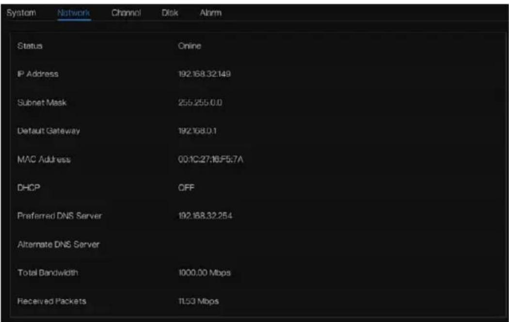
Channel: channel, name, status, video format, resolution, bitrate (kbps), and so on, as shown in Figure 7-82.
Figure 7-82 Information-channel interface
| System | Network | Channel | Disk | Alarm | ||
| Channel | Name | Status | Video Format | Resolution | Bhstrate(kbps) | |
| CH1 | Channel01 | Online | H265/H265 | 100*1080/704*576 | 4896/1024 | |
| CH2 | Channel02 | Offline | H265/H265 | 3640*7180/720*576 | 4296/706 | |
| CH3 | Channel03 | Online | H265/H265 | 2550*1500/104*5.76 | 4896/1024 | |
| CH4 | Channel04 | Online | H265/H265 | 3,80*1,500/704*5.76 | 4896/1024 | |
| CH5 | Channel05 | Online | H265/H265 | 1660*1080/704*580 | 4896/1024 | |
| CH6 | Channel06 | Online | H265/H265 | 704*480/352*240 | 2900/1024 | |
| CH8 | Channel08 | Offline | H265/H265 | 3640*260/720*576 | 4396/788 | |
Disk: disk name, capacity, used, SN, disk model, status, and so on, as shown in Figure 7-83
Figure 7-83 Information-disk interface

Alarm: channel, name, mode, enable, recording channel, and so on, as shown in Figure 7-84.
Figure 7-84 Information-alarm interface
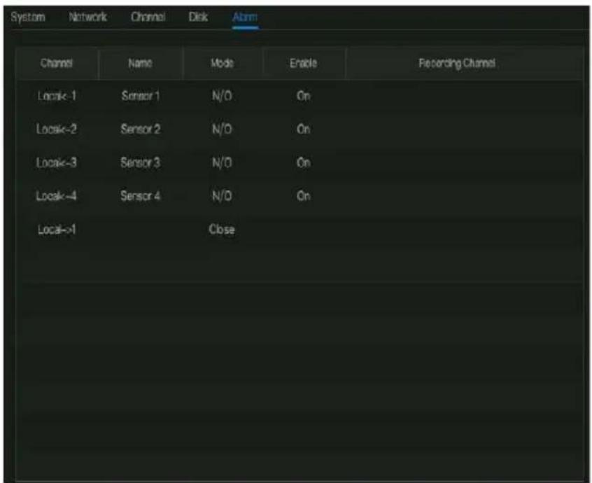
----End
7.5.2 General
7.5.2.1 System
Operation Steps
Step 1 Click General in the main menu or menu of the system management screen and choose General to access the system screen, as shown in Figure 7-85.
Figure 7-85 system setting screen

Step 2 Enter the name of the selected device.
Step 3 Select a proper resolution from the output resolution drop-down list.
Step 4 Select a required language from the Language drop-down list.
Step 5 Set the temperature unit.
Step 6 Click Apply to save settings.
----End
7.5.2.2 Date and Time
Operation Steps
Step 1 Click Date and Time page to access the date and time setting screen, as shown in Figure 7-86.
Figure 7-86 Date and Time setting screen
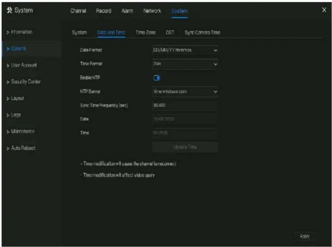
Step 2 Select required format from the Date Format and time format drop-down list.
Step 3 Click Next to NTP Sync to disable time synchronization. Time synchronization is enabled by default. Time is synchronized with the NTP.
Step 4 After NTP Sync is disabled, you can manually set the system time:
Click Date and use the scroll wheel to select the year, month, and date.
Click Time and use the scroll wheel to select the hour, minute, and second.
Click Modify Time to save the time settings.
Step 5 Click Apply to save settings.
----End
7.5.2.3 Time Zone
Operation Steps
Step 1 Click Time zone page to access the time zone setting screen, as shown in Figure 7-87.
Figure 7-87 Time zone setting screen

Step 2 Select a required time zone from the Time Zone drop-down list.
Step 3 Click Apply Settings.
----End
7.5.2.4 DST
When the DST start time arrives, the device time automatically goes forward one hour (offset time). When the DST end time arrives, the device time automatically goes backward one hour. The offset time can change if the local rule is different.
Operation Steps
Step 1 Click DST page to access the DST setting screen, as shown in Figure 7-88.
Figure 7-88 DST setting screen

Step 2 Click to DST to enable DST.
Step 3 Select start time, end time, offset time from the drop-down list respectively, that basis on the local rules.
Step 4 Click Apply to save settings.
----End
7.5.2.5 Sync Camera Time
Enable the sync camera time, the channels will show the sync time, and set the frequency of check
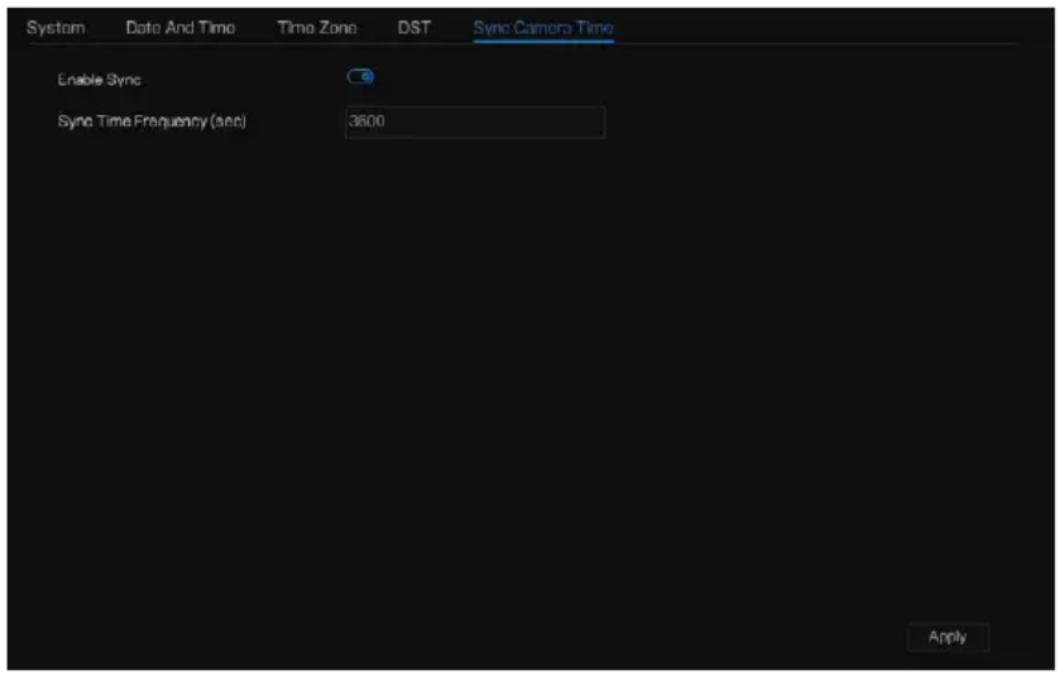
----End
7.5.3 User Account
Add, modify, and delete a user and privilege in user screen, admin user can dispose privilege to different users.
7.5.3.1 User
Operation Steps
Step 1 Click User in the main menu or menu of the system management screen and choose User to access the user screen, as shown in Figure 7-89.
Figure 7-89 User management screen

Step 2 Add or delete a user.
- Add a user
Click Add, the Add User dialog box appears, as shown in Figure 7-90.
Figure 7-90 Add user screen

Input a username, password and confirm password, choose group and change password reminder, set the expire date.

NOTE
The password should include at least two types of letters, characters and numbers.
The password should be 6\~32 characters long.
Step 3 Select a Group from the drop-down list box.
Step 4 Select a Change password reminder value from the drop-down list box.
Step 5 Enable the expire date to set the new user's authority time.
Step 6 Select the operation privileges and channels in the list of the add user screen.
Step 7 Click OK User is set successfully.

NOTE
The default user is Administrator and cannot be deleted or modified.
Select a user from user list and click to edit, or click to delete a user.
----End
7.5.3.2 Advance Setting
Operation Steps
Step 1 Click User in the main menu or menu of the system management screen and choose Adv Setting to access the user screen, as shown in Figure 7-91.
Figure 7-91 Advance setting screen

Step 2 Enable or disable Double Authentication, Auto login, Setup Wizard. Set the logout time if the user disables the auto login.
Step 3 Choose monitor channels when logout, the default is all channels.
Step 4 Click Apply Settings.
----End
7.5.3.3 App Verification
Add the digital number to whitelist, When log in to the mobile app to manage the NVR, enter a series of numbers in the whitelist for testing and verifying to ensure security.
Figure 7-92 App verification

Up to 20 groups of security codes can be added and notes can be modified for them.
Tick the numbers, click “-” to delete the numbers.
Click Apply a setting.
----End
7.5.4 Security Center
7.5.4.1 Password
Operation Steps
Step 1 Click Security Center in the main menu or menu of the system management screen and choose Password to access the modify password screen, as shown in Figure 7-93.
Figure 7-93 Password modification screen
![System Channel Record Alarm Network System Information General User Account Security Center Layout Auxiliary Screen Logs Maintenance Auto Roboot Password Pattern Unlock Secure Email Secure Question Old Password Password New Password Password Confirm Password Password - Valid password range [6-32] ch…](/content/2026/05/1015136/images/f4b94d76f3cb3e0c45b6db0be50731a3b9349dedc46b199cf4466da494133c1d.jpg)
Step 2 Input the correct old password, new password, and confirm password.

NOTE
The password should include at least two kinds of letter, character and number.
The password should be 6\~32 characters.
Only special characters (! @#&*+=-%&"'(),/' .:;<>?^|\~[] {} ) are supported,
Step 3 Click Apoly modified password settings.
----End
7.5.4.2 Pattern Unlock
Operation Steps
Step 1 Click Security Center in the main menu or menu of the system management screen and choose Pattern Unlock to access the modify pattern unlock screen, as shown in Figure 7-94.
Figure 7-94 Pattern unlock screen

Step 2 Input the password, enable pattern unlock.
Step 3 Click Setting Pattern to set an new pattern unlock.
Step 4 Draw the pattern, then it will remind to draw the confirmation pattern again.
Step 5 Click OK the pattern unlock.
----End
7.5.4.3 Secure Email
Set the email to receive the verification code to create new password, as shown in Figure 7-95.
Figure 7-95 Secure Email

Step 1 Input the password of NVR.
Step 2 Set the Email address to receive verification code.
Step 3 Click Apply Cutting.
----End
7.5.4.4 Secure Question
Set the questions to create new password, as shown in Figure 7-95.
Figure 7-96 Secure question

Step 1 Input the password of NVR.
Step 2 Choose the question from drop-down list.
Step 3 Input the answer, click Apply Setting.
----End
7.5.5 Layout
Set viewing video mode, dwell time in display screen. The layout is set as auto sequence multiple screen.
Operation Steps
Step 1 Click Layout in the main menu or menu of the system management screen and choose Layout to access the display screen, as shown in Figure 7-97.
Figure 7-97 Auto Sequence screen
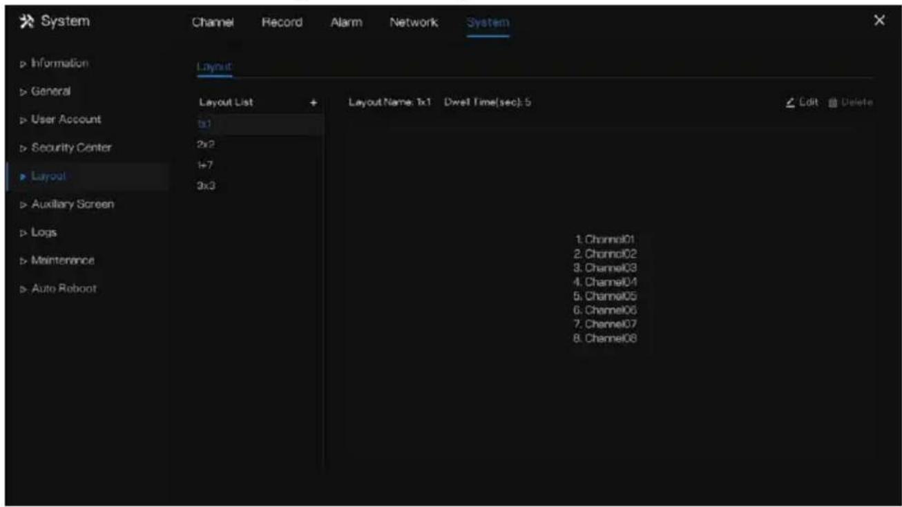
Step 2 Click “+” to add a new layout. The default layout is one splitting screen.
Figure 7-98 Add a new layout
![Add Layout Channel [1]Channel01 [2]Channel02 [3]Channel03 [4]Channel04 [5]Channel05 [6]Channel06 [7]Channel07 [8]Channel08 [-]Empty Layout Name Dwell Time(see) 5 OK Cancel](/content/2026/05/1015136/images/221eca8718138d482c4f418c04651c86a845dc32cd497a79f5c90109415f1f10.jpg)
Step 3 Input the layout name, select dwell time from the SEQ Dwell time drop-down list(the display screen will loop play the real time video according to setting time).
Step 4 Select split screen mode at the bottom of the page. Set the channel display by dragging the channel to specific position, or select the position first, then click the channel. A split screen can play multiple channels. Auto sequence means it will play according to the setting. For example, the first split screen is set as two pages (channel 1 and 2), the second split screen is set as one page (channel 3). When auto sequence is enabled, channel 1 and channel 3 are displayed, then channel 2 and channel 3 are displayed.
Figure 7-99 Auto sequence
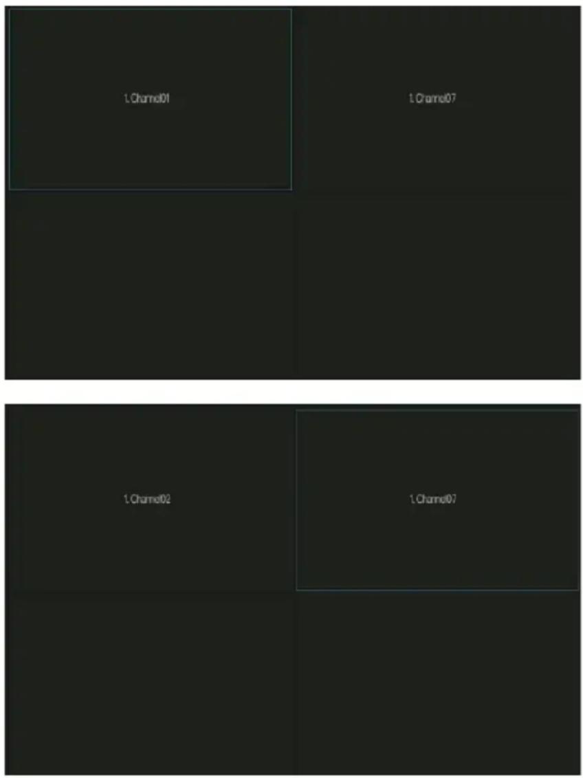
Step 5 Click Apply to save a well settings.

NOTE
User can add up to 16 layouts.
----End
7.5.6 Auxiliary Screen (Only for Some Models)

NOTE
This function only can be used for the devices with 8 or more than channels. The main screen is connected by HDMI (HD-OUT 2), auxiliary screen is connected by VGA.
Operation Steps
Step 1 Click Auxiliary Screen in the main menu or menu of the system management screen.
Step 2 Enable the auxiliary screen, as shown in Figure 7-100
Figure 7-100 Auxiliary screen

Step 3 Set the Output Resolution, Decoding Ability(main + auxiliary), Layout Mode, Display Channel.
Step 4 Enable tour to set Auto Sequence of auxiliary screen as shown in.
Figure 7-101 Auto sequence of auxiliary screen

Step 5 Click Apply Settings.

NOTE
The auxiliary screen shows different channels with main screen, and the auto sequence show all channels.
The auxiliary screen will show the personnel counting information if it is enabling.
----End
7.5.7 Logs
7.5.7.1 System Log
Search for logs information and export the information of logs.
Operation Steps
Step 1 Click Logs in the main menu or menu of the system management screen and choose Logs to access the log screen, as shown in Figure 7-102.
Figure 7-102 Log screen

Step 2 Set start date, end date, start time and end time of the logs on log screen.
Step 3 Select logs type from the drop-down list.
Step 4 Click Search to query logs.
Step 5 Click Export logs to flash disk.
Step 6 the logs can be saved to flash disk and hard disk at the same time, the newest logs is saved to flash disk, and the old logs will be transferred to hard disk.
----End
7.5.7.2 Event Log
Event logs are divided into more detailed types, which can be found quickly. Its operation is the same as the system log, please refer to chapter 7.5.7.1.
Figure 7-103 Event
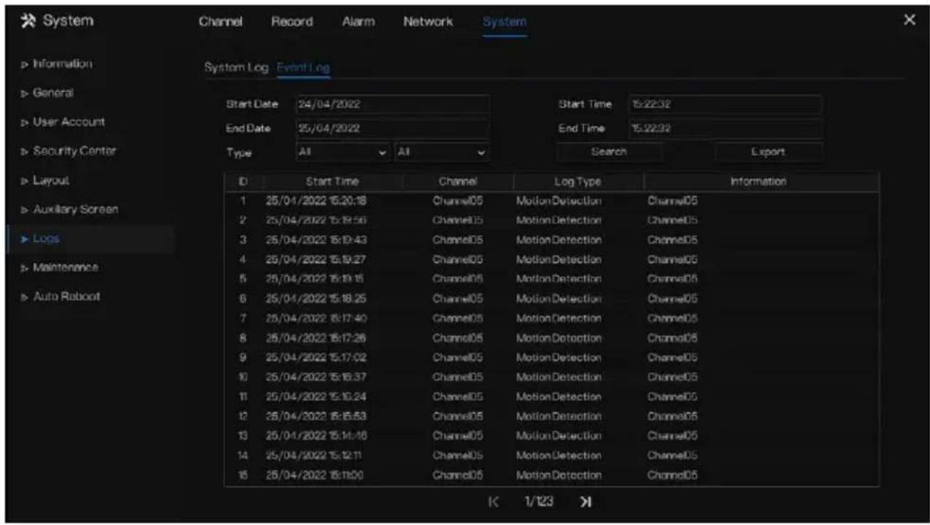
7.5.8 Maintenance
Operation Steps
Step 1 Click Maintenance in the main menu or menu of the system management screen and choose Maintenance to access the maintenance screen, as shown in Figure 7-104.
Figure 7-104 Maintenance screen

Step 2 Click Shutdown, Reboot, Logout, Exit system, Reset or update to operate NVR if you need.
Figure 7-105 Firmware update

Step 3 Click import configuration or export configuration to view the message “Are you sure to import the configuration?” Make sure the flash driver is working.
Step 4 The tips will show on screen, click ok to ensure choice.
Step 5 Click Import Config to import the configuration to flash drive.
Step 6 Import the configuration, the device would restart immediately.
Step 7 Click Export Config to export the configuration from flash drive.

NOTE
When the NVR finishes updating, the device would restart.
Network packet capture: the NVR is plugged into the USB disk, click the network packet capture, and set the relevant parameters of the packet capture. The captured data can be downloaded and used for device problem analysis.
FW Update, firmware update; Plug in the U disk with the update software, choose the file to update.
Save running log: In the U disk to save the running log.
----End
7.5.9 Auto Reboot
Operation Steps
Step 1 Click Auto reboot in the main menu or menu of the system management screen and choose Auto reboot to access the maintenance screen, as shown in Figure 7-104.
Figure 7-106 Auto restart screen

Step 2 Enable the function, restart time is showing as figure
Restart Time Par Day 0:00
Step 3 Restart the NVR per day, week or month.
Step 4 Select the restart time from the drop-down list.
----End
8 WEB Quick Start
The functions of Web are the same as those of UI system, all functions can be referred to chapter 7 UI system setting.
8.1 Activation
If you don't set the password at UI interface, user need activate the device, as shown in Figure 8-1 Activation

Step 1 Set the password, and confirm the password.
Step 2 Input the channel password.
Step 3 Set the email to recovery the password.
Figure 8-2 Email
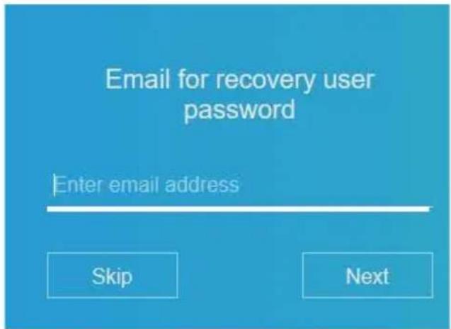
Step 4 Set the question to recovery the password.
Figure 8-3 Question


NOTE
If you don't set the email or question, you can skip the steps.
8.2 Login and Logout

CAUTION
You must use Firefox 53, Chrome 45 or Edge to access the Web interface. Otherwise, the interface functions cannot be used normally.
The win 7/ win 10 system supports Firefox/Chrome, but the XP system does not.
Brower supports 32 bits systems.
Descriptions of browser:
To access the client by using Chrome 42-44, you need to enable manually Npapi in the browser according to following steps:
- In the Chrome address bar, enter chrome://flag/#enable-npapi.
- Go to the experimental features' management page.
- Enable NAPAPI Mac, Windows.
- Click Enable (NPAPI plugin is enabled).
- Re-launch Chrome.
Here we take IE 10 as an example for videos viewing.
Login
Step 1 Open IE browser, enter the IP address of the NVR (default value: 192.168.0.121) in the address box, and press Enter.
The login page is displayed, as shown in Figure 8-4.
Figure 8-4 Login page interface

Step 2 Input the user name and password.

NOTE
The default user name and password both are admin. The password is incorrect more than 3 times, please log in again after 5 minutes.
User can change the system display language on the login page.
The modify password page pop-up window would show when login the NVR for the first time.
Step 3 Click Login to access the homepage, as shown in Figure 8-5.
Figure 8-5 Homepage interface 1

Logout
To logout of the system, click in the upper right corner of the homepage. The pop-up
message shows “Would you like to exit?” Click OK and the login page will display.
Homepage Layout
NVR allows you to use the Web interface in a PC for implementation of such functions as live video, playback, retrieval, setting, image parameters access, configuration, PTZ control and so on. Figure 6-8 shows the overall layout of the interface. For descriptions of the interface, please refer to Table 8-1.
Figure 8-7 Homepage layout

Table 8-1 Descriptions of homepage
| No. | Function | Description |
| 1 | Function navigation bar | Main functions navigation bar of the device, it includes Live Video, Playback, Alarm Search, Face Recognition, Attendance and System Setting. |
| 2 | Alarm | Alarm notification. User can tick pop-up message to monitor, system alarm and channel alarm. |
| 3 | Logout button | User can click Logout to exit the current account and return to the login interface. |
| 4 | Help | Help for running environment, plug-in installation and activation. |
| 5 | Device's list | Display a list of the channels of the managed NVR and the channels managed by NVR. |
| 6 | Real-time video | Display the real-time videos of the channels managed by NVR. |
| 7 | Channel Operation | Include snapshot, record, stream switch and audio on/off. |
| 8 | PTZ control button |  Click low PTZ control buttons in zone 10, you can control the PTZ equipment in the current channels.That function only uses for IP dome camera. Click low PTZ control buttons in zone 10, you can control the PTZ equipment in the current channels.That function only uses for IP dome camera. |
| 9 | Color parameter button |  Click low color parameter setting buttons in zone 9, you can set and adjust the color parameters, for example, brightness, contrast, saturation, and sharpness. Click More to access image settings. Click low color parameter setting buttons in zone 9, you can set and adjust the color parameters, for example, brightness, contrast, saturation, and sharpness. Click More to access image settings. |
| 10 | Operation zone | The operation zone of PTZ control and image parameter setting. |
| 11 | Layouts | Select the one-screen, four-screen, nine-screen or sixteen- screen to switch the layout. |
| 12 | Manual alarm | Trigger and close the external alarm device manually. |
----End
8.3 Browsing Videos
8.3.1 Browsing Real-Time Videos
You can browse real-time videos in the web management system.
Preparation
To ensure that real-time videos can be played properly, perform the following operations when you log in to the web management system for the first time:
Step 1 Open Internet Explorer. Choose Tools > Internet Options > Security > Trusted sites >
Sites. In the displayed dialog box, click Add, as shown in Figure 8-8.
Figure 8-8 Adding a trusted site


Step 2 In Internet Explorer, choose Tools > Internet Options > Security > Customer level, and set Download unsigned ActiveX controls and Initialize and script ActiveX controls not marked as safe for scripting under ActiveX controls and plug-ins to Enable, as shown in Figure 8-9.
Figure 8-9 Configuring ActiveX controls and plug-ins


Step 3 Download and install the player control as prompted. During installing, you need to close the browser.

NOTE
If the repair tips displayed when installing the control, close the browser and continue the installation, reopen the login page when the control is installed.
8.3.2 Live Video
Descriptions
After login the device, click online channel, you can view the real-time videos, as shown in Figure 8-10.
Figure 8-10 Real-time videos interface

----End
8.3.3 Channel Operation
Descriptions
Channel operation includes snapshot, record, stream switch and audio on/off. Table 8-2 describes the operations.
Table 8-2 Descriptions of homepage
| Buttons | Button description | How to operate |
| Snapshot | Click button to take snapshots of the current image. | |
| Record | Click button to start recording and click button again to stop recording. | |
| Switch stream | Click button to switch stream 1 (main stream) and stream 2(sub stream). | |
| Enable/Disable video | Click button to enable the audio and click again to disenable the video. |
----End
8.3.4 PTZ Control and Setting
Descriptions
The PTZ control and setting function applies only to Network Dome or camera connected to an external PTZ.
PTZ Setting
If a Network Dome or a camera connected to PTZ had been added to the NVR channel, users can control the PTZ rotation to adjust their shooting angle when you are viewing the video. This allows you to perform Omni-directional video surveillance.

Click 📄, the PTZ operation and setting interface is as shown in Figure 8-11. Table 8-3 describes the operations.
Figure 8-11 PTZ control interface

Table 8-3 Device parameters
| Buttons | Button description | How to operate |
 | Direction key | Click button to control omni-directional movement of the PTZ. |
 | Speed slider | Drag the slider to adjust the value of PTZ rotation speed. |
 | Zoom in | Click buttons to adjust the focal length. |
 | Zoom out | |
 | Iris+ | Click buttons to adjust the aperture. |
 | Iris- | |
 | Far focus | Click buttons to adjust the focal length. |
 | Near focus | |
 | Auto focus | Click button to focus automatically. |
 | Home preset | N/A |
 | Preset | The camera is set the tour, click the button and dome camera rotate as the setting. |
 | More | More settings, scan and tour |
8.3.5 Sensor Setting
Descriptions
The sensor setting can adjust scene, brightness, sharpness, contrast and saturation, click

access image setting, as shown in Figure 8-12. Table 8-4 describes the operations.
Figure 8-12 Image parameter interface
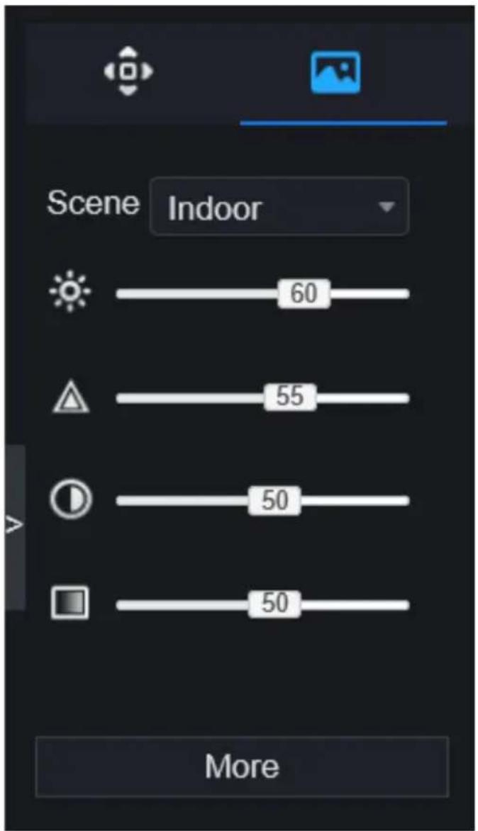
Table 8-4 Device parameters
| Buttons | Button description | How to operate |
 | Brightness | Click button to adjust the image brightness. |
 | Sharpness | Click button to adjust the image definition. |
 | Contrast | Click button to adjust the transparency of the image. |
 | Saturation | Click button to adjust the chromatic purity of the image. |
Click more will be access to system sensor setting. As shown in Figure 8-13, for more detail please refer to chapter Figure 4-7.
Figure 8-13 Sensor setting interface

----End
8.3.6 Layout

Click at the bottom left corner of real-time videos interface, the buttons
indicate 1 screen, 4 screens and 9 screens from left to right. The device with more POE ports can support 16 screens layout.
----End
8.4 Playback
8.4.1 Video Playback
Video playback refers to playing of videos stored in local hard disks.
Procedure
Step 1 Click in the function navigation bar, the video playback interface is displayed, as shown in Figure 8-14.
Figure 8-14 Video playback
![NVR Device [1] Alt [2] Channel12 [3] Channel029 [4] Devos 06/13/2021 05:47:19 Hour B X: 9999 12/06/2021 22:47:22 Hour 12/06/2021 22:47:22 Hour DRAKJ 06/13/2021 05:47:19 Hour 12/05/2021 22:47:21 Hour DIN DH FST DH Schedule Report Manual Review Auto Recycler](/content/2026/05/1015136/images/94a1a4e651d804b8da6931f0e094d2abd6ccb420e7c300cba096491b95ddd96c.jpg)
Step 2 Select a channel. Click a device in the device list. A selected device is marked with .
The unselected device is marked with

Step 3 Select a date from calendar at left bottom, the date will be colored if it has record as shown in upper figure.
Step 4 Tick the type of record, such as schedule record, manual record and alarm record. Step 5 Display videos.
After a device and date are selected, video information is displayed below the video pane. The time scale above the file axis shows the different time points of video recording. The time in blue in the middle is the time of the video playing.
The file axis displays videos. The blue file axis indicates a video exits, grey file axis indicates no video exits.
You can drag the axis to play recording quickly.
You can play a video after selecting a device and date. Figure 8-15 shows the control bar of video playback.
Figure 8-15 Control bar


: reversed.

:play/pause.

triple speed.

: split screen. One or four screens.

: sync/async. You can set the different channels to play synchronously or asynchronous.
Sync mode indicates the selected channels play video synchronously. Async mode indicates users play different time period record

: types of time bar.

: user can operate the record as same as live video.
----End
8.5 Alarm Search
You can search for channel alarm and system alarm in the alarm search interface.
8.5.1 Channel Alarm
Procedure
Step 1 Click to the function navigation bar, the channel alarm interface is displayed, as shown in Figure 8-16.
Figure 8-16 Channel alarm interface
![NVR Device [1] up [2] Channel12 [3] Channel24 [4] Device Start Time 19:05:24:24 08:31:10 End Time 14:05:24:24 08:31:10 Alert In Camera Alarm In Verizon Detection Camera Terrier Video Lines Transgen Analysis Antenna Alert Search ID Start Time Channel Type Information Controls Total Number 0](/content/2026/05/1015136/images/4278e20154efd0d0b43dc4b5d4b85685c86bcc45fa512ff4d2a7fb42083e1838.jpg)
Step 2 Choose the alarm type to search.
Step 3 Click Search, the result will be displayed as shown in Figure 8-17.
Figure 8-17 Channel alarm result
![NVR Device [1] Channel01 [2] Channel02 [3] Channel03 [4] Channel04 [5] Channel05 [6] Channel06 [7] Channel07 [8] Channel08 Start Time 24/04/2022 16:12:35 End Time 25/04/2022 16:12:35 ■ Alarm In ■ Camera Alarm In ■ Motion Detection ■ Camera Timer ■ Video Loss + ■ Intelligent Analysis + ■ Abnormal Ala…](/content/2026/05/1015136/images/56b1e00269b99bea636be91678e15ae46f739d4fa4f65b12f4459d1d84854beb.jpg)

NOTE
Click to select the page of alarm list.

shows the rows shown in every page.
----End
8.6 Attendance (Only for Some Models)
8.6.1 Attendance Data
Click to enter attendance data interface, as shown in Figure 8-18.
Figure 8-18 Attendance data

Operation Steps
Step 1 Tick the attendance library.
Step 2 Choose time mode, such as today, this week, this month and custom time.
Step 3 Choose search type, such as attendance summary and attendance details.
Step 4 Click search, the result will show in interface.
Step 5 Click Export to export the query result.
----End
8.6.2 Attendance Management
In attendance management, user can set attendance rule, library and check point, as shown in Figure 8-19.
Figure 8-19 Attendance rule settings

Operation Steps
Step 1 Set start work time and end work time.
Step 2 Tick the workdays.
Step 3 Set valid time of check in and check out.
Step 4 Click Save to save the setting.
Attendance library
Step 1 Click Attendance Library to add library, the attendance library can call the face database directly.
Figure 8-20 Attendance library
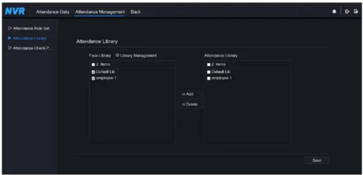
Step 2 Tick the library and click Add to add to attendance library. If you want to modify the library, please enter to library interface to change parameters..
Step 3 click Database management management to modify
parameter.
Step 4 Click Save to save the setting.
Attendance check point settings:
Step 1 Click Attendance check point settings to set point, as shown in Figure 8-21.
Figure 8-21 Attendance check point setting

Step 2 Click edit check point setting, as shown in Figure 8-22
Figure 8-22 Check point

Step 3 Enable the function, set similarity and tick the library, all face detection cameras can be set the check points.
Step 4 Click OK to save the setting.
----End
8.7 AI Recognition (Only for Some Models)
At AI recognition interface, we can set the Real time Comparison, Smart search, Archives library, Comparison configuration.
8.7.1 Real Time Comparison
Real time comparison can compare human face, vehicle license plate, and AI(include riding, vehicle, full body)
8.7.1.1 Human Face
At real time comparison interface, click the user enter the human face comparison interface, choose the cameras with face recognition function to play live video, the snapshot of camera will be compared with libraries, the result shows as in Figure 8-23.
Figure 8-23 Human face comparison

Click the “+” to add the snapshot to face library immediately.
----End
8.7.1.2 Vehicle License Plate
At real time comparison interface, click the ☐ enter the vehicle license plate comparison interface, choose the cameras with license plate recognition function to play live video, the snapshot of camera will be compared with libraries, the result shows as in Figure 8-24.
Figure 8-24 Vehicle license plate

Click the “+” can add the snapshot to license plate library immediately.
To get snapshot in real time video, put the cursor on picture such as your photo add it to
face library, or face search. The cursor on area 6 and the pictures are not update, move the mouse so that the pictures can be shown in time.
----End
8.7.1.3 Vehicle and Full Body
At real time comparison interface, click the “no” to enter the vehicle license plate comparison interface, choose the AI recognition cameras to play live video, the snapshot of camera will compare with libraries, the snapshot to vehicle and full body will show at the bottom of page, the result shows as in Figure 8-25.
Figure 8-25 Full body
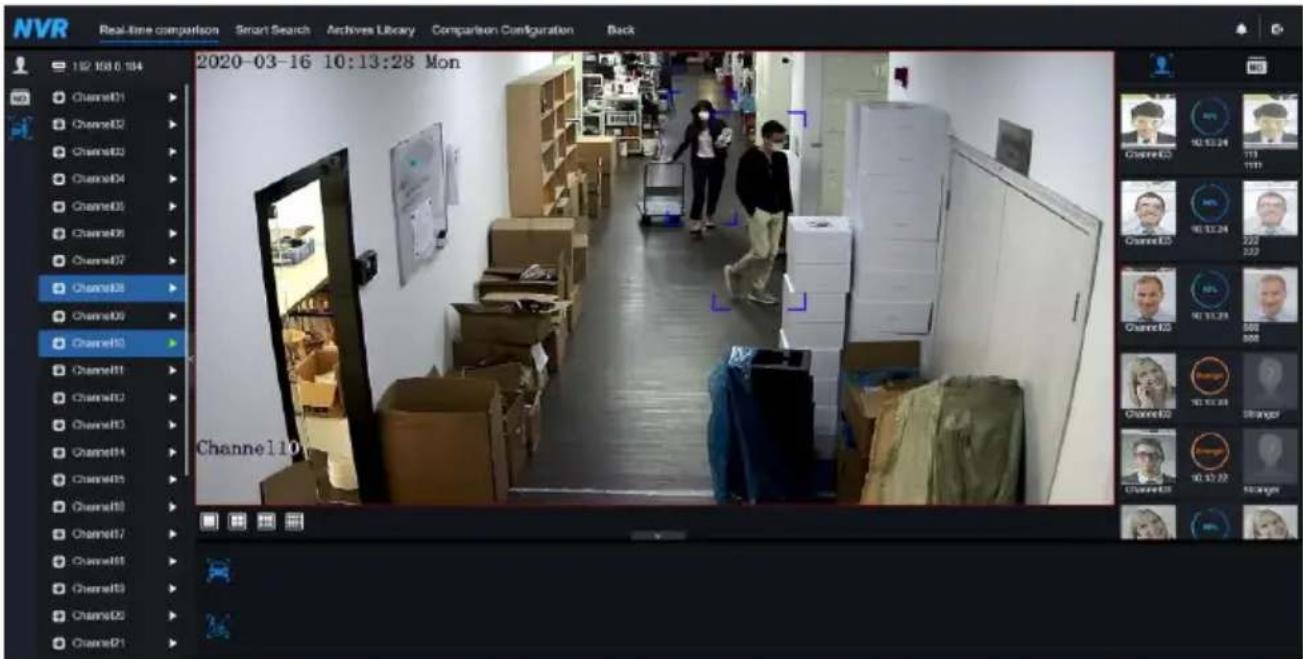
8.7.1.4 Real Time Body Temperature Filter
The real time body temperature will show the snapshot of device, it shows the over temperature and snapshot to human face.
Snapshot will show the characteristic such as no mask (the mask detection configuration can be set at comparison configuration interface)
Figure 8-26 Body temperature

----End
8.7.2 Smart Search
At smart search interface, users can search the human face, vehicle license plate, full body, car, body temperature.
8.7.2.1 Human Face Search
Figure 8-27 Human face search

Step 1 Choose human face search at smart search interface.
Step 2 Tick the face recognition camera channels, set the start time and end time.
Step 3 Choose the condition (by picture or by feature), the picture can be chosen from the file folder.
Step 4 Click "Search" to search the snapshot of human face.
Step 5 The result will show at the middle of page, click the picture and detailed information at the top right of page.
Step 6 Detailed picture can be used to search or add to library.
Step 7 Click play button of video to play the recordings of snapshot.
----End
8.7.2.2 Vehicle License Plate Search
Figure 8-28 Vehicle License Plate search

Step 1 Choose vehicle License Plate at smart search interface.
Step 2 Tick the vehicle license plate recognition camera channels, set the start time and end time.
Step 3 Input the license plate optionally.
Step 4 Click "Search" to search the snapshot of license plate.
Step 5 The result will show at the page, click “+” add to library.
----End
8.7.2.3 Full Body Search
Figure 8-29 Full body search

Step 1 Choose full body search at smart search interface.
Step 2 Tick the AI recognition camera channels, set the start time and end time.
Step 3 Set the gender, click cycling or no cycling.
Step 4 Click "Search" to search the snapshot of human face.
Step 5 The result will show at the middle of page, click the picture and the detail information show at the top right of page.
Step 6 Click play button of video to play the recording of snapshot.
----End
8.7.2.4 Vehicle Search
Figure 8-30 Vehicle search

Step 1 Choose vehicle search at smart search interface.
Step 2 Tick the AI recognition camera channels, set the start time and end time.
Step 3 Tick the color.
Step 4 Click “Search” to search the snapshot of human face.
Step 5 The result will show at the middle of page, click the picture and detailed information at the top right of page.
Step 6 Click play button of video to play the recordings of snapshot.
----End
8.7.2.5 Body Temperature Search
Figure 8-31 Body temperature search

Step 1 Choose body temperature search at smart search interface.
Step 2 Tick the AI recognition camera channels, set the start time and end time.
Step 3 Choose the person type, temperature type, input ID optionally.
Step 4 Click "Search" to search the temperature.
----End
8.7.2.6 Personnel Count
If the AI camera connect to NVR, the NVR can obtain the data of camera directly. Set the statistical type (day, month, year), choose the time to search.
The result can show as line graph, histogram, or list, as shown in Figure 8-32.
Figure 8-32 Personnel count

----End
8.7.3 Archives Library
At archives library, users can add or edit the face library, license plate library.
8.7.3.1 Face Library
Figure 8-33 Face library

Click “+” to add face library.
Click "Add" to add person enroll.
Tick the person, click "Delete" to delete the person.
Click "Import" to add the person batch.
Click "Export" to export all people in library.
Click operate icon to edit or delete the chosen person.
To get snapshot in real time video, put the cursor on picture such as , you can add it to
face library, or face search. The cursor on area 6 and the pictures are not update, move the mouse so that the pictures show in time.
----End
8.7.3.2 License Plate Library
Figure 8-34 License plate library

Click “+” to add license plate library.
Click "Add" to add plate to library.
Tick the plate, click "Delete" to delete the license plate.
Click "Import" to add the license plate batch.
Click "Export" to export the all-license plate library.
Click operate icon to edit or delete the chosen license plate.
----End
8.7.4 Comparison Configuration
At comparison configuration interface, users can set the comparison of human face/ license plate/temperature.
Figure 8-35 Face comparison

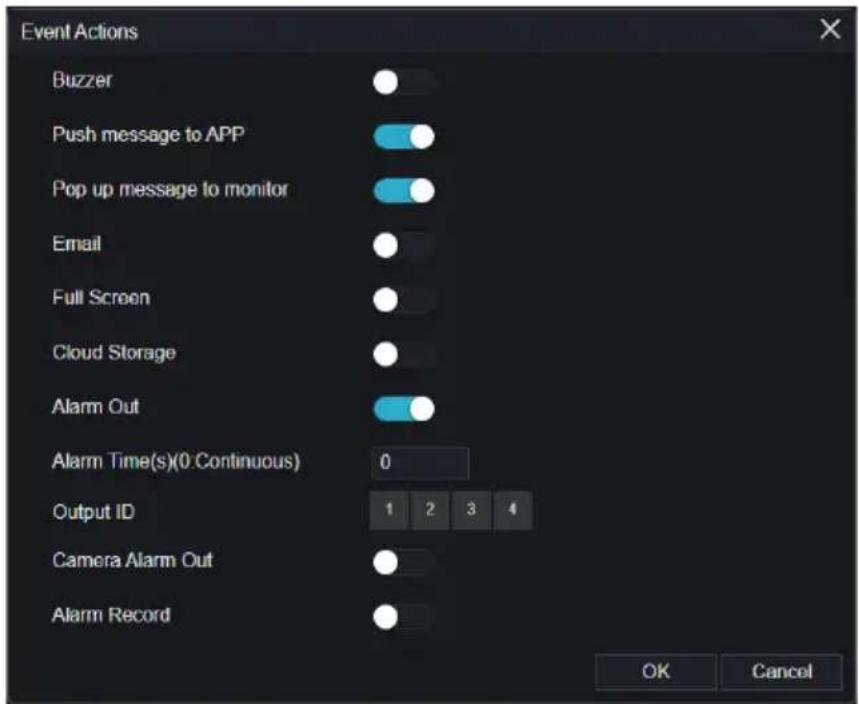
At face comparison interface, users can set different channels' strategy, such as similarity, display comparison result, face library, enable alarming, event action, schedule, as shown in Figure 6-35.
Figure 8-36 License comparison
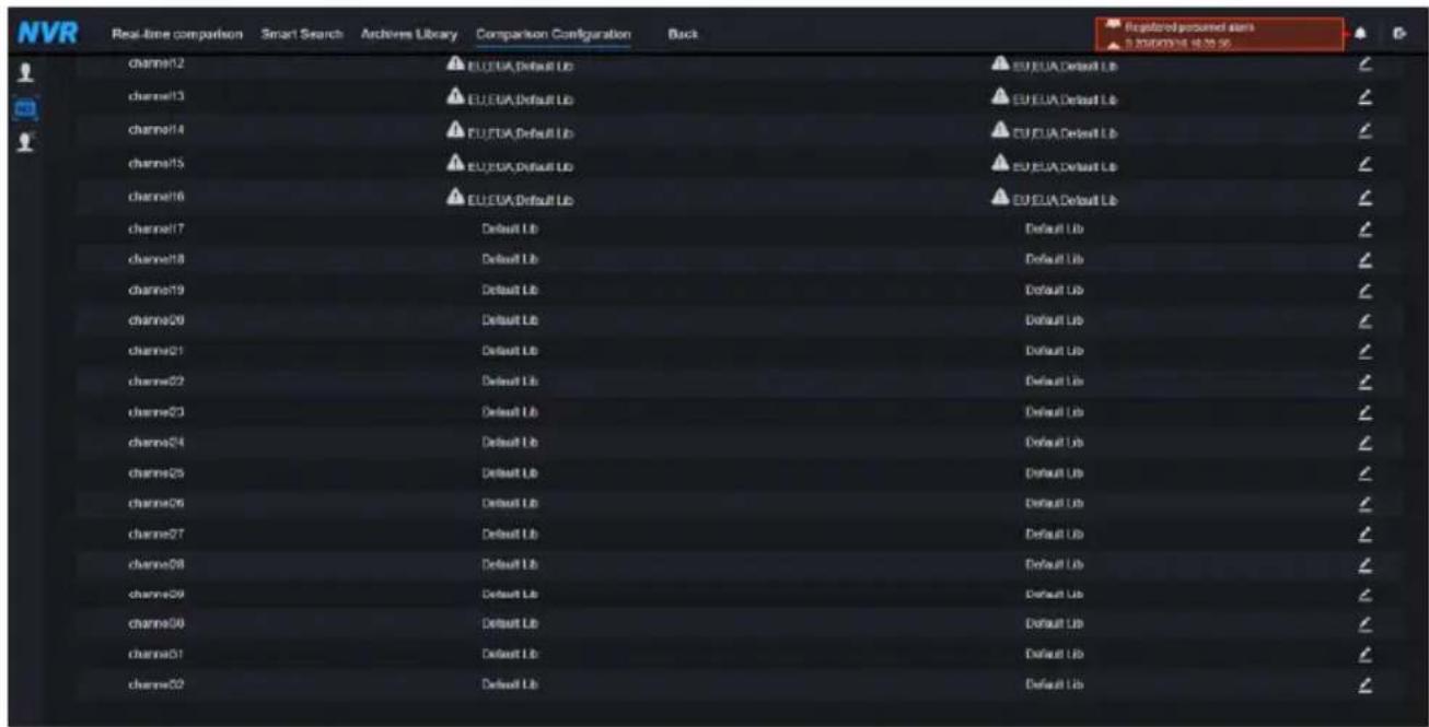
At license plate interface, users can set strategies of different channels of license plate recognition cameras, such as register and unregister, enable alarming, event action, schedule, as shown in Figure 8-36.

means the library is deleted.
Figure 8-37 Temperature comparison
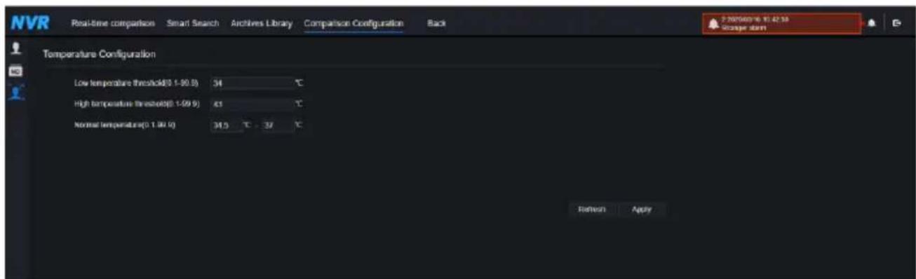
At temperature comparison interface, users can set low temperature threshold, high temperature threshold, normal temperature, as shown in Figure 8-37.
Figure 8-38 Strategy

Mask detection configuration: enable mask detection, set the mode (wear mask, no mask). Set confidence degree, the default value is 90. Click “apply” to save the settings.
Figure 8-39 Mask detection configuration

Enable mask alarm linkage, set the event action and schedule.
Figure 8-40 Schedule linkage
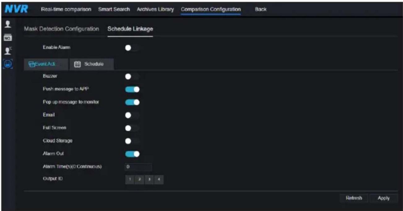
The alarm information is relevant to mask detection configuration.
----End
9 System Setting
The system setting allows you to set system, channel, record, alarm, network and local setting.
9.1 Channel
User can set parameter about camera, encode, sensor setting, OSD and privacy zone.
9.1.1 Camera
Step 0 On the System Setting screen, choose Channel > Camera to access the camera interface, as shown in Figure 9-1.
Figure 9-1 Camera interface

Step 1 Input username and password (the default username and password both are admin), and
Click To Add click add cameras automatically.
Step 2 Click Search to search cameras at the same LAN as NVR, as shown in Figure 9-2.
Choose the cameras, input username and password, click Add to add new cameras.
Figure 9-2 Device search

Step 3 Click Back to back to camera interface.
Step 4 Click Refresh to refresh cameras status.
Step 5 Choose the cameras and click to delete.
Step 6 Click Batch Update to update all selected cameras at once, the pop-up window would show to select software.
Step 7 Click to modify the information of device parameters, as shown in Figure 9-3.
Figure 9-3 Modify device parameters

Step 8 Click to add camera manually, click the added channel to copy information to add, so that user just modify some information quickly, as shown in Figure 9-4.
Figure 9-4 Add camera manually

Step 9 Click to access web immediately.

The pop-up message “Are you sure to restart the device?” “Are you sure to reset?
Reserve IP Address" would respectively show.
Figure 9-5 Modify IP


NOTE

: it indicates the camera is online, users can view the live video immediately.

: it indicates the camera is offline, it may be not connected to the network, or the password is
incorrect. Access to the modify device parameters interface to change.
9.1.1.1 Protocol Management
Set the protocol management, users can add different protocol cameras to NVR
Figure 9-6 Protocol management
![Camera Protocol Management Custom Protocol Custom Protocol 1 Protocol Name Custom 1 Stream Type Main Stream Sub Stream Type RTSP RTSP Port 554 554 Path Example [Type]: [P Address] (Port) [Path] Refresh Apply](/content/2026/05/1015136/images/7c8b95811870ee48402ee2b03cdfdc629004bb5263f002ee707fe720ba0170c4.jpg)
Step 1 Click Channel > Camera > RTSP Connection.
Step 2 Choose the custom protocol from the drop-down list, there are 16 kinds of protocols can be set.
Step 3 Input the protocol name.
Step 4 Tick main stream and sub stream. The main stream shows image on full screen live video. The sub stream shows image on split screen. If you just tick main stream and the channel will not show image on split screen.
Step 5 Choose the type of protocol, the default value is RTSP.
Step 6 Input the port of the IP camera.
Step 7 Input the path, which decided by the manufacturer of cameras.
Step 8 Click to save the settings.
9.1.2 Encode
Step 1 On the System Setting screen, choose Channel > Encode to access the encode interface, as shown in Figure 9-7.
Figure 9-7 Encode interface
![Encode Channel [1]Channel01 Stream Information Main Stream Video Format H265 Audio Encode Type G711A Resolution 1920x1080 Frame Rate(fps) 25 I Frame Interval(Frame) 50 Bitrate Type CBR Bitrate(kbps)(500-6144) 4096 Smart Encode Copy Apply](/content/2026/05/1015136/images/416b73cdba996f8d8c2954280d1785451d3cbca3b5a2174b0943760683b61d4b.jpg)
Step 2 Select a channel from drop-down list.
Step 3 Select stream information, encode type, resolution, frame rate, bitrate control and bitrate from drop-down list.
Step 4 Click Copy to choose other camera to copy settings. Click Apply to save the settings.
----End
9.1.3 Sensor Setting
Step 1 On the System Setting screen, choose Channel >Sensor Setting to access the sensor setting interface, as shown in Figure 9-8.
Figure 9-8 Image interface
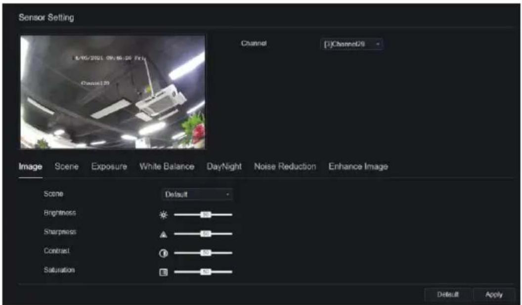
Step 2 Select a channel and scene from drop-down list.
Step 3 Set image parameters, like scene, brightness, sharpness, contrast and saturation.
Step 4 Other parameters are camera's senor setting, please refer IP cameras' settings.
Step 5 Click Copy to choose other cameras to copy settings. Click Apply to save the settings.

NOTE
Brightness: It indicates the total brightness of an image. As the value increases, the image becomes brighter.
Sharpness: It indicates the border sharpness of an image. As the value increases, the borders become clearer, and the number of noise points increases.
Saturation: It indicates the color saturation of an image. As the value increases, the image becomes more colorful.
Contrast: It indicates the measurement of different brightness levels between the brightest white and darkest black in an image. The larger the difference range is, the greater the contrast is the smaller the difference range is, the smaller the contrast is.
Scene: it includes indoor, outdoor, default. Mirror includes normal, horizontal, vertical, horizontal + vertical.
Exposure: it includes mode, max shutter, meter area and max gain.
White balance: it includes tungsten, fluorescent, daylight, shadow, manual, etc.
Day-night: it transit day to night, or switch mode.
Noise reduction: it includes 2D NR and 3D NR.
Enhance image: it includes WDR, HLC, BLC, defog and anti-shake.
Zoom focus: zoom and focus.
----End
9.1.4 OSD
Step 1 On the System Setting screen, choose Channel >OSD to access the OSD interface, as shown in Figure 5-4
Figure 9-9 OSD interface
![OSD Channel [1]Channel01 Time Channel Name Channel01 Name Copy Apply](/content/2026/05/1015136/images/269b022e3ad8c4bb8fbd3b8e8380af1532108a82ac3b6eba457de1ed1a900318.jpg)
Step 2 Select a channel and scene from drop down list.
Step 3 Enable time and channel name. You can set channel name. Drag the icon of Channel Name or Date and Time to move, select the location.
Step 4 Click to choose other cameras to copy settings. Click to save the settings.

----End
9.1.5 Privacy Zone
Step 1 On the System Setting screen, choose Channel >Privacy Zone to access the privacy zone interface, as shown in Figure 9-10.
Figure 9-10 Privacy interface
![NVR Channel Camers Encode Sensor Setting OSD Privacy Zone ROI Microphone Human Thermometer Smart Intelligent Tracking Record Alarm Network System Privacy Zone 05/14/2021 09:40:35 Fri Channel [2]Channel12 Click and hold left button and drag to select an area Double click an area to delete it Supports…](/content/2026/05/1015136/images/b5e0712ac806c44c20a62ad1c106bfc6b75277aa461709a54ca7df190f7fd4e9.jpg)
Step 2 Select a channel from drop-down list.
Step 3 Drag the mouse to select area to cover with rectangle frame. You can set less than four areas to be covered. Double click would delete the area.
Step 4 PTZ can be used for adjusting the IP dome cameras.
Step 5 Click to choose other cameras to copy settings. Click to save the settings.

----End
9.1.6 ROI
ROI(Region of interest), choose channel, stream, area ID and draw the area. Set the level, there are five levels can be chosen. Set area name, click “Apply” to save the settings.
Figure 9-11 ROI
![Channel Camera Encode Sensor Setting OSD Privacy Zone ROI Microphone Human Thermometer Smart Record Alarm Network System ROI Channel [28]Channel28 Stream Sub Stream Area ID 1 Enable Level 5 Area Name Note: Max size 50% Light click to remove the zones drawn Only special characters are supported @4%*(…](/content/2026/05/1015136/images/a78a1ea18cc7b7eaa39f9855fabfc22af2c01444a31e1ec18356e4348bf6192f.jpg)
9.1.7 Microphone (Only for Some Models)
Users can set the microphone parameters of channel.
Figure 9-12 Microphone
![Channel Camera Encode Sensor Setting OSD Privacy Zone ROI Microphone Human Thermometer Smart Record Alum Network System Microphone Channel [1]Channel01 - Microphone Microphone Type Line in - Microphone Volume - + 50 Apply](/content/2026/05/1015136/images/51131d97a5703638af538d6381ce2ebe1d99eaa809ae911add388d65c83d95c8.jpg)
9.1.8 Human Thermometer (Only for Some Models)
Users can set the parameters of human thermometer cameras, such as parameter configure, thermal mapping, thermal calibration, for more detail please refer to the UI settings.
Figure 9-13 Human thermometer
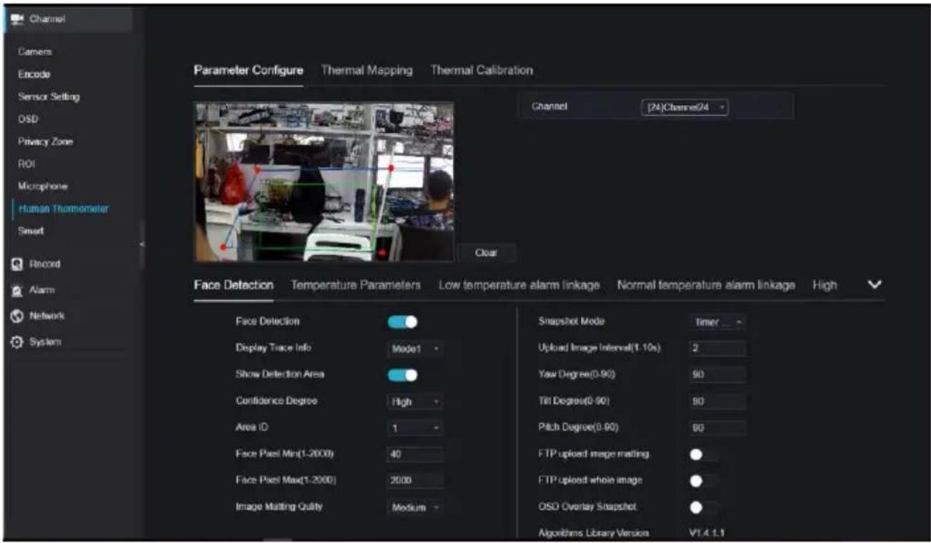
9.1.9 Smart (Only for Some Models)
At smart interface, users can set AI multiobject, license plate recognition, face detection.
Figure 9-14 Smart interface
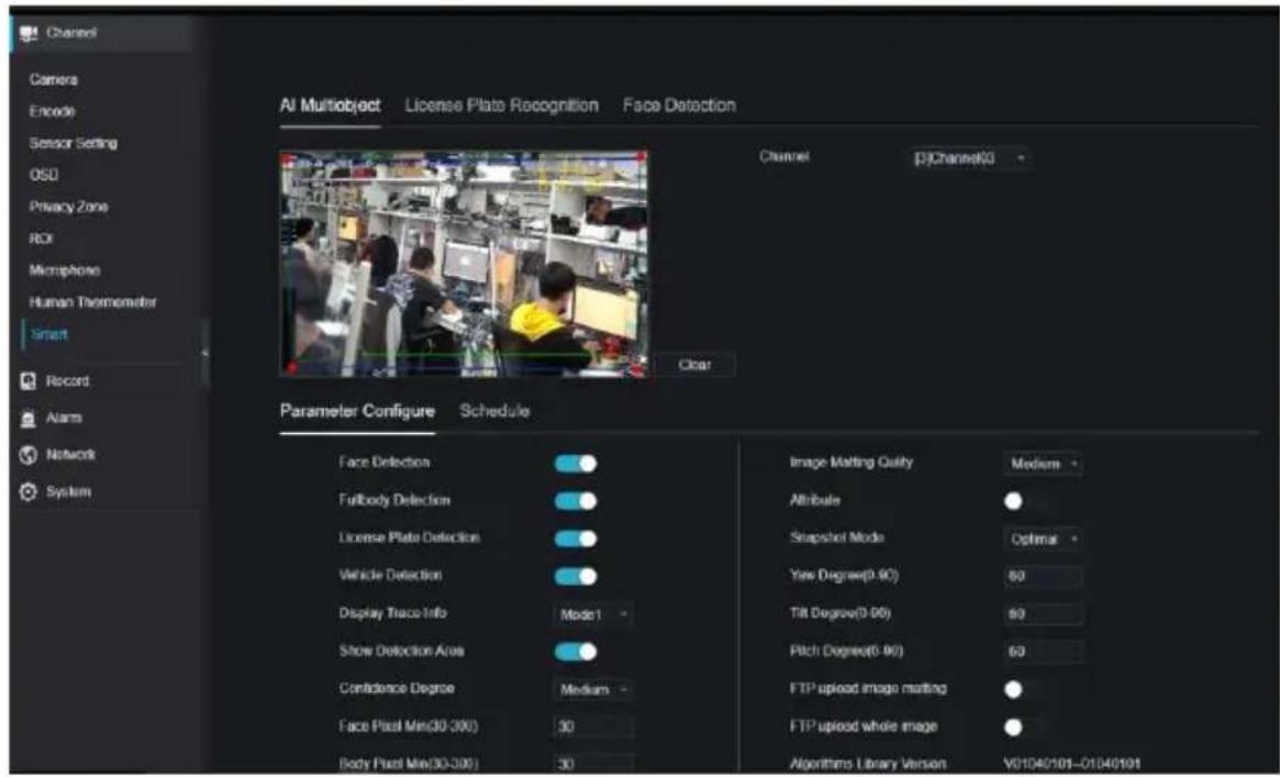
9.1.10 Intelligent Tracking (Only for Some Models)
This function can only be used for high speed dome camera. It works with PTZ function.
Figure 9-15 Intelligent tracking
![NVR Channel Camera Encode Sensor Setting OSD Privacy Zone ROI Microphone Human Thermometer Smart Intelligent Tracking Channel [2]Channel12 - Intelligent Tracking Calibration Coefficient - + 0 Trace Magnify - + 0 Time Of Duration(s) - + 0 Apply Record Alarms Network System](/content/2026/05/1015136/images/9cdf46c37c76618bb7c21cfeafd8151c9339df6ed6425cd3ee8f3816c477bff5.jpg)
The detailed information please refer to UI configuration setting.
9.2 Record
Users can set record policy in storage interface.
9.2.1 Record Schedule
Procedure
Step 1 On the System Setting screen, choose Record > Record schedule to access the record schedule interface, as shown in Figure 9-16.
Figure 9-16 Record schedule interface

Step 2 Select a channel.
Step 3 Enable the record, then enable record audio.
Step 4 Enable ANR, when the IP cameras support the ANR, if the cameras are disconnected to NVR, the NVR can copy the loss video recordings from SD card installed in cameras.
Step 5 Set the record schedule, you can drag the mouse to choose area, click to choose all day or all week, you can also click one by one to set the schedule. Or dray the mouse cursor to choose. Users can set the alarm recording to save the space of disk.
Step 6 Click to return the previous settings.
Step 7 Click Copy to choose other cameras to copy settings. Click Apply to save the settings.
----End
9.2.2 Disk
Step 1 On the System Setting screen, choose Record >Disk to access the disk interface, as shown in Figure 9-17.
Figure 9-17 Disk interface

Step 2 You can view the information like capacity, disk status, disk SN code and used space.
Step 3 Click to delete all data. Before deleting data users will view pop-up window
"Are you sure to format disk? Your data will be lost". Click OK to delete, click Cancel to quit.
Step 4 Choose the disk group from drop-down list, there are four disk groups.
Step 5 Enable the recording overwrite, set the expired time. (If the expired time is 0, it means the disk is full, then the recording will be rewrite. It the expired time is 5 days, the recording video will be rewrite when it reaches the expiration date..)
Step 6 If the recording overwrite is disable, set the expired time, it is up to 90 days.
----End
9.2.3 Storage Mode
Distribute channels to different disk groups as needed for efficient use of the disk capacity.
Figure 9-18 Storage Mode
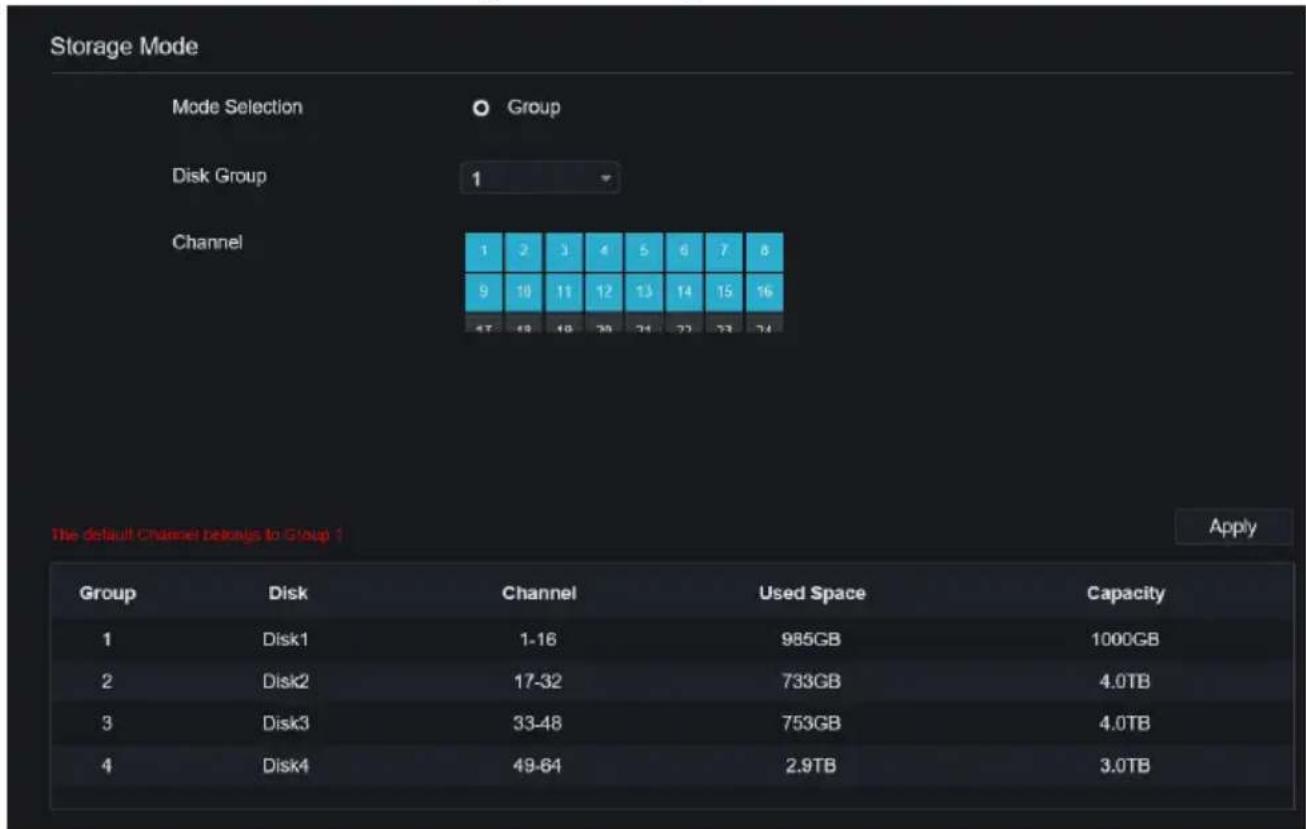
Operation Steps
Step 1 Choose the disk group.
Step 2 Select the channel to record to disk group.
Step 3 Click Apply to save the settings.
Step 4 The group list will show the detail information.
9.2.4 RAID (Only for Some Models)

NOTE
RAID is only used for the device with 4 disks or more. And the disks must be enterprise level disks. It is recommended to choose the same capacity for efficient use.
For Raid5, at least 3 disks can be created. For RAID6, at least 4 disks can be created. For RAID10, at least 4 disks can be created. Creating a hot spare disk requires more disks.
It is recommended to choose the same capacity for efficient use. The RAID with less than 100T capacity can be built.
Figure 9-19 RAID

Operation Steps
Step 1 Click RAID to create the RAID.

Step 2 Click Create to choose disk to create a new RAID.
Step 3 Tick the Hot-spare Disk to back up the broken disk in case, the number of disk must be more than basic disks.
Step 4 Click to save the operation, format the new RAID

Step 5 Click format it will show

Figure 9-20 Modify the RAID

9.2.5 S.M.A.R.T
S.M.A.R.T is Self-Monitoring Analysis and Reporting Technology, users can view the health of disk, as shown in Figure 9-21.
Figure 9-21 S.M.A.R.T

The disk of Western Digital can be viewed by WDDA, as shown in Figure 9-22.
Figure 9-22 WDDA (Supplied for Some Model)
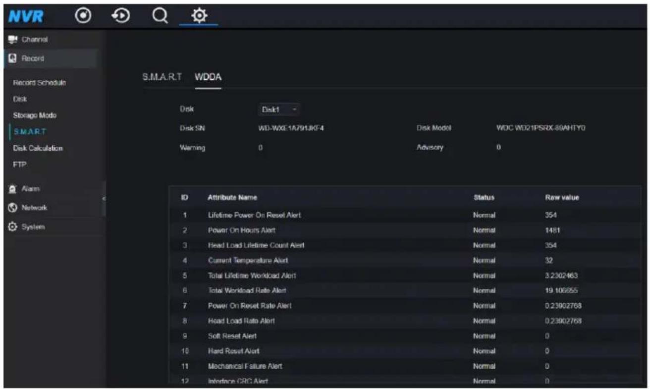
9.2.6 Disk Calculation
There are two modes to calculate the captivity of disk, as Computing Capacity Computation time shown in.
Figure 9-23 Disk calculation


9.2.7 Cloud Storage (Only for Some Models)
User copy the authorization code path to browser to enter Google Drive interface. Google sends the code, and users input the code to authority NVR, so the device can set the alarm recording to Google drive.
Figure 9-24 Cloud Storage


NOTE
Enable the alarm of cloud storage at first so that the Google drive can receive the recoding.
Cloud storage can only be set at motion detection and intelligent analysis interface.
9.2.8 FTP
Set the FTP path to receive the alarm information, as shown in Figure 9-25. More detail information please refer to UI interface parameters.
Figure 9-25 FTP

9.3 Alarm
Users can set general, motion detection, video loss, intelligent analysis and alarm in on alarm interface.
9.3.1 General
9.3.1.1 General
Procedure
Step 1 On the System Setting screen, choose Alarm > General to access the general interface. Step 2 Enable alarm to set duration time and buzzer duration time, as shown in Figure 9-26.
Figure 9-26 General interface

Step 3 Click to save settings. Click to return to the previous settings.
9.3.1.2 IO Control Push
Procedure
Step 1 On the System Setting screen, choose Alarm > General > IO Control Push to access the general interface.
Step 2 Enable the IO control push, as shown in Figure 9-27.
Figure 9-27 IO control push interface

Step 3 Choose one alarm in and mode (N/C, N/O).
Step 4 Tick the disable items, click "Apply" to save settings.
----End
9.3.2 Motion Detection
Procedure
Step 1 On the System Setting screen, choose Alarm > Motion Detection to access the motion detection interface, as shown in Figure 9-28.
Figure 9-28 Motion detection interface
![Motion Detection Channel [1]Channel/01 Enable Motion Detection Event Actions Detection Area Schedule Buzzer Push message to APP Pop up message to monitor Full Screen Email FTP PTZ Enable Alarm Out Enable Camera Alarm Out Enable Event Recording Copy Apply](/content/2026/05/1015136/images/251bb98a8407ff98f80a202cfb517c2a29ba7b11e130e59a336ce081331ec593.jpg)
Step 2 Click channel drop-down list to choose channel.
Step 3 Enable motion detection alarm.
Step 4 Set Event Activity, includes buzzer, push message to APP, pop-up message to monitor, full screen, Email, cloud storage, alarm out (the back panel), channel alarm out (the port of cameras), and alarm record.
Step 5 Click Area to access the motion detection area setting, as shown in Figure 9-29.
Figure 9-29 Motion detection area interface
![Motion Detection Channel [1]Channel01 Enable Motion Detection Event Actions Detection Arms Schedule Sensitivity Medium Copy Apply](/content/2026/05/1015136/images/c5c93307939851bcf54ee1854393267edae58365189bd7a9233dc3bb36d3d386.jpg)
- Hold down and drag the left mouse button to draw a motion detection area.
- Select a value from the drop-down list next to Sensitivity.
- Double -click the chosen area to delete.
Step 6 Click Schedule to access schedule settings, drag and release mouse to select the alarming time within 00:00-24:00 from Monday to Sunday. Click the chosen area can cancel. The settings of alarm schedule are same as disk schedule.
Step 7 Click to choose other cameras to copy settings. Click to

save the settings.
---End
9.3.3 Video Loss
Procedure
Step 1 On the System Setting screen, choose Alarm > Video Loss to access the video loss interface, as shown in Figure 9-30.
Figure 9-30 Video loss interface
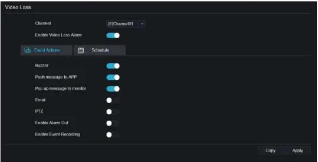
Step 2 Click drop-down list to choose channel.
Step 3 Enable the video loss alarm.
Step 4 Set event activity and schedule please refer to Figure 5-1 motion detection settings.
Step 5 Click to choose other camera to copy settings. Click to save Apply
the settings.
----End
9.3.4 Intelligent Analysis (Only for Some Models)
Procedure
Please refer to chapter 7.4.1 video loss settings, interface displayed as shown in Figure 9-31.
Figure 9-31 Intelligent analysis interface
![Intrusion Line Crossing Double Virtual Fences Object Left Object Removed Signal Bad Loiter Multi Loiter Channel [3]Channel03 Enable Event Actions Detection Area Schedule Buzzer Push message to APP Pop up message to monitor Full Screen Email FTP PTZ Enable Alarm Out Enable Camera Alarm Out Enable Eve…](/content/2026/05/1015136/images/b6c370cef95b12690dd80776609fe6e03c0b28ffa7b94e1f8604895d9dd27574.jpg)
9.3.5 Alarm In
Procedure
Step 1 On the System Setting screen, choose Alarm > Alarm In to access the alarm in interface, as shown in Figure 9-32.
Figure 9-32 Alarm in interface
![Alarm In Alarm In [1]Alarm In Enable Alarm Type N/O Name Sensor 1 Event Acti... Schedule Buzzer Push message to APP Pop up message to monitor Email Alarm Out Alarm Time(s)(0:Continuous) 0 Output ID 1 2 3 4 Alarm Record Apply](/content/2026/05/1015136/images/6b29aa3fcb4fcb47be79bc642a713ff388bf744b49c492cff8d6d68c631d15fa.jpg)
Step 2 Click drop-down list to choose alarm in.
Step 3 Enable the button, choose alarm type.
Step 4 Set name, default as Sensor 1.
Step 5 Set event activity and schedule please refer to motion detection settings.
Step 6 Click to save settings.
----End
9.3.6 Abnormal Alarm
Procedure
Step 1 On the System Setting screen, choose Alarm > Abnormal Alarm to access the abnormal alarm interface, as shown in Figure 6-12.
Figure 9-33 Abnormal alarm interface
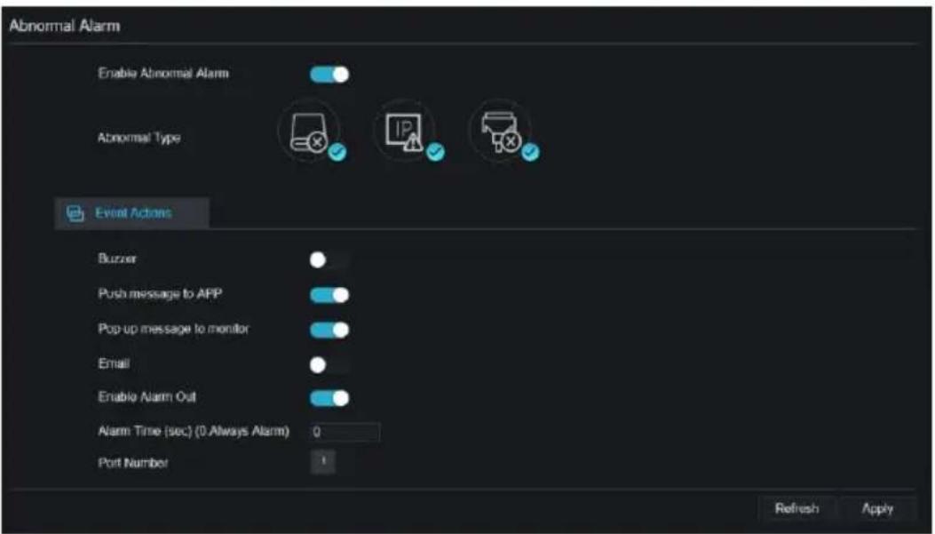
Step 2 Enable the button, tick alarm type.
Step 3 Set event activity and schedule please refer to motion detection settings.
Step 4 Click to save settings.
----End
9.3.7 Alarm out
Set the alarm out, the camera alarm out.
Figure 9-34 Alarm out
![Alarm Out Camera Alarm Out Port Number [1]Alarm Out Port Name Valid Signal Close Alarm Output Mode Switch Mode Refresh Apply](/content/2026/05/1015136/images/8b2a66d5a83f8a8b46df16591f6a5c719ac1f0ad82475251f036f1be2123db60.jpg)
Figure 9-35 Camera alarm out
![Alarm Out Camera Alarm Out Channel [1]Channel01 Port Number 1 Port Name Valid Signal Close Alarm Output Mode Switch Mode Alarm Time(ms)(0 Continuous) 0 Refresh Apply](/content/2026/05/1015136/images/b64b8d7c4bc61dedd53e675988f78aad4a7de96628bec9934d8c83f1ccc46783.jpg)
9.4 Network
Users can set Network, DDNS, E-mail, UPnP, P2P, IP Filter, 802.1X, SNMP and Web Mode.
9.4.1 Network
Procedure
Step 1 On the System Setting screen, choose Network > Network to access the network interface, as shown in Figure 9-36.
Figure 9-36 Network interface

Step 2 Choose network card from the drop-down list. Network card I is LAN1, network card II is LAN2, as shown in Figure 9-37.
Figure 9-37 Network card II

Step 3 Click next to IP to enable or disable the function of automatically getting an IP
address. The function is enabled by default.
If the function is disabled, click input boxes next to IP, Subnet mask, and Gateway to set the parameters as required.
Step 4 Click next to Obtain DNS Automatically to enable or disable the function of
automatically getting a DNS address. The function is enabled by default.
If the function is disabled, click input boxes next to DNS1 and DNS2, delete original addresses, and enter new addresses.
Step 5 Set PORT and POE manually, input the information about these.
Figure 9-38 POE

Step 6 Click Refresh to restore previous settings. Click Apply to save the settings. ----End
9.4.2 DDNS
Procedure
Step 1 Click DDNS in the network interface, choose Network > DDNS to access the DDNS interface as shown in Figure 9-39.
Figure 9-39 DDNS interface

Step 2 Click the button to enable the DDNS function. It is disabled by default.
Step 3 Select a required value from the protocol drop-down list.
Step 4 Set domain name, user, and password.
Step 5 Click to restore previous settings. Click to save the settings.

NOTE
An external network can access an address specified in the DDNS settings to access the NVR.
----End
9.4.3 Email
Procedure
Step 1 Click Email in the network interface, choose Network > Email to access the E-mail interface, as shown in Figure 9-40
Figure 9-40 Email interface

Step 2 Set SMTP server and SMTP server port manually.
Step 3 Set sender E-mail, user name and password manually.
Step 4 Set E-mail for receiving the alarm message.
Step 5 Set E-mail for retrieving the password.
Step 6 Click SSL Encryption drop-down list to enable safeguard of email.
Step 7 Click Refresh to restore previous settings. Click Apply to save the settings.
----End
9.4.4 Port Mapping
Step 1 Click Port Mapping in the network interface, choose Network > Port Mapping to access the UPnP interface as shown in Figure 9-41.
Figure 9-41 Port Mapping interface

Step 2 Select manner from UPnP enable drop list. The default value is auto.
Step 3 After UPnP is manual, set the Web port, data port and client port manually.
Step 4 Click to restore previous settings. Click to save the settings.

NOTE
Auto: System perform UPnP automatically.
Manual: The ports are distributed by the router. Input them according to the router.
9.4.4.2 NAT port
NAT (Network Address Translation), users can browse the web of camera by NAT port. There are five ports can be assigned to each camera. Input the start port, the system will compute the end port automatically.
Figure 9-42 NAT port
![Channel Record Alarm Network Network DDNS Email Port Mapping P2P IP Filter 802.1X SNMP Web Mode 3C/4G PPPOE System Port Mapping NAT Port Start Port 50002 End Port 50161 Port range [40001-65534] Refresh Apply](/content/2026/05/1015136/images/dd1b49b5930622ea918aff6082b239d56e13c051c682f6033d1e27c22a22ad74.jpg)
----End
9.4.5 P2P
Procedure
Step 1 Click P2P in the network interface, choose Network > P2P to access the P2P interface, as shown in Figure 9-43.
Figure 9-43 P2P interface

Step 2 Click Enable to enable the P2P function.
Step 3 Click to restore previous settings. Click to save the settings
Step 4 After installing Inview Pro 4 in mobile phone, run the app and scan the UUID QR code to add it. And then access the NVR while the device is online.
----End
9.4.6 IP Filter
Procedure
Step 1 Click IP Filter in the network interface, choose Network > IP Filter to access the IP filter interface, as shown in Figure 9-44.
Figure 9-44 IP filter interface

Step 2 Click Enable to enable the IP filter function.
Step 3 Click drop-down list of rule type to choose black list or white list.
Step 4 Click ,view the pop-up windows to set black list or white list, as shown in 7.5.5.
Click to delete the list.
Figure 9-45 Black or white list interface

Step 5 Set start IP and end IP.
Step 6 Click to deny settings, click to save the settings.
Step 7 Click to save the previous settings. Click to save the setting

NOTE
Black list: IP address in specified network segment to prohibit access. White list: IP address in specified network segment to allow access. Select a name in the list and click Delete to delete the name from the list. Select a name in the list and click Edit to edit the name in the list. Only one rule type is available, and the last rule type set is efficient.
----End
9.4.7 802.1X
Procedure
Step 1 Click 802.1X in the network interface, 802.1X interface is displayed, enable the button, as shown in Figure 9-46.
Figure 9-46 802.1X interface
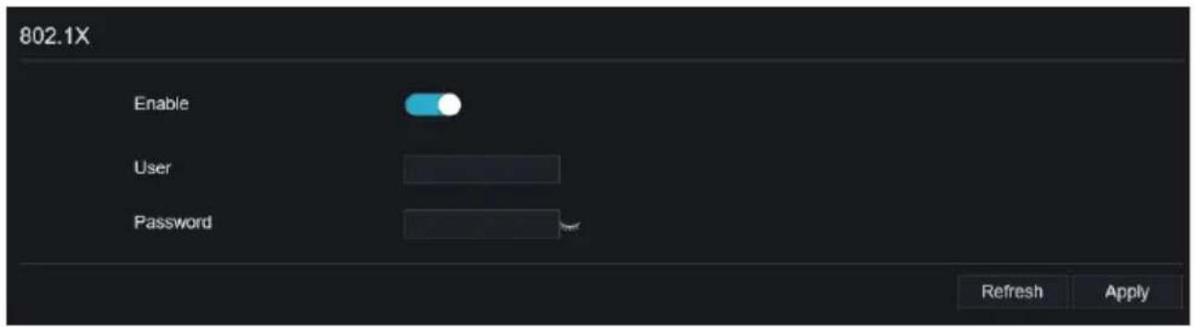
Step 2 Input the user and password of 802.1X authentication.
Step 3 Click to remove previous settings. Click to save the settings.
----End
9.4.8 SNMP
Procedure
Step 1 Click SNMP in the network interface, SNMP interface is displayed, enable the button next to SNMPV1, as shown in Figure 9-47.
Figure 9-47 SNMP interface


Step 2 Input the information of SNMP (simple network management protocol). there are three types of that function. Users can apply that if need.
Table 9-1 SNMP parameters
| Parameter | Description | Setting |
| SMTP Server Address | IP address of the SMTP server. | [Setting method]Enter a value manually. |
| SMTP Server Port | Port number of the SMTP server. | [Setting method]Enter a value manually.[Default value]25 |
| User Name | User name of the mailbox for sending emails. | [Setting method]Enter a value manually. |
| Password | Password of the mailbox for sending emails. | [Setting method]Enter a value manually. |
| Sender E-mail Address | Mailbox for sending emails. | [Setting method]Enter a value manually. |
| Recipient_E-mail_Address1 | (Mandatory) Email address of recipient 1. | [Setting method]Enter a value manually. |
| Recipient_E-mail_Address2 | (Optional) Email address of recipient 2. | |
| Recipient_E-mail_Address3 | (Optional) Email address of recipient 3. | |
| Recipient_E-mail_Address4 | (Optional) Email address of recipient 4. | |
| Recipient_E-mail_Address5 | (Optional) Email address of recipient 5. | |
| Attachment Image Quality | A higher-quality image means more storage space. Set this parameter based on the site requirement. | N/A |
| Transport Mode | Email encryption mode. Set this parameter based on the encryption modes supported by the SMTP server. | [Setting method]Select a value from the drop-down list box.[Default value]No Encrypted |
Step 3 Click to restore previous settings. Click to save the settings.
----End
9.4.9 Web Mode
Step 1 Click Web Mode in the network interface, Web mode interface is displayed, as shown in Figure 5-1.
Figure 9-48 Web mode interface

Step 2 Enable the https, the device will restart and start https secure.
Step 3 Click to restore previous settings. Click to save the settings.
----End
9.4.10 3G/4G
Figure 9-49 3G/4G

Step 1 The user plugs the modem to NVR.
Step 2 Enable the 3G/4G.
Step 3 When the status is connected, users can set the access mode, AUTO is recommended.
Step 4 If choose other access mode, users should input the parameter correctly.
Step 5 Click to restore previous settings. Click to save the settings.
9.4.11 PPPOE
Users can use PPPOE function to manage the NVR conveniently.
Figure 9-50 PPPOE

Step 1 Enable the PPPOE.
Step 2 Input the username and password.
Step 3 The IP address is obtained automatically.
Step 4 Click to restore previous settings. Click to save the settings. Apply
Step 5 User use the IP address to access NVR immediately.
9.4.12 POE Status (Only for Some Models)
Users can view the POE status at this interface, as shown in Figure 9-51.
Figure 9-51 POE status
![graph TD A["Internet"] --> B["Router"] B --> C["Power Supply"] style A fill:#f9f,stroke:#333 style B fill:#ccf,stroke:#333 style C fill:#cfc,stroke:#333](/content/2026/05/1015136/images/d59742a120f205cba33d792c05d91fd29d922602fb714281f3e4f0c145525aab.jpg)
9.4.13 Platform Access
For more detail, please refer to UI interface parameter setting 7.4.13 Platform Access.
Figure 9-52 Platform access

9.5 System
Users can set parameters about information, general, user, password, logs, maintenance and auto restart.
9.5.1 Device Information
Procedure

Step 1 Click on the navigation bar, the device information interface is displayed, as shown in Figure 9-53.
Figure 9-53 Device information interface
| System | Network | Channel | Disk | Alarm |
| Device ID | B011003AFEK109U62 | |||
| Device Name | Device | |||
| Device Type | NVR | |||
| Model | NVR3808E2-P8E-J | |||
| Firmware Version | v4 6 1604 0000.003 0.1 38 0 | |||
| U-boot Version | 1504010C0F18 | |||
| Kernel Version | 15080511183A | |||
| HDD Number | 2 | |||
| Channels Supported | 8 | |||
| Alarm In | 8 | |||
| Alarm Out | 1 | |||
| Audio In | 1 | |||
| Audio Out | 1 |
Step 2 Set the device name according to Table 9-2.
Table 9-2 Device parameters
| Parameter | Description | Setting |
| Device ID | Unique device identifier used by the platform to distinguish the devices. | [Setting method]The parameter cannot be modified. |
| Device Name | Name of the device. | [Setting method]System Setting > GeneralModify the device name. |
| Device Type | N/A | [Setting method]These parameters cannot be modified. |
| Model | ||
| Firmware version | ||
| HDD volume | ||
| Channel support | ||
| Alarm in | ||
| Alarm out | ||
| Audio in | ||
| Audio out |
Figure 9-54 Network
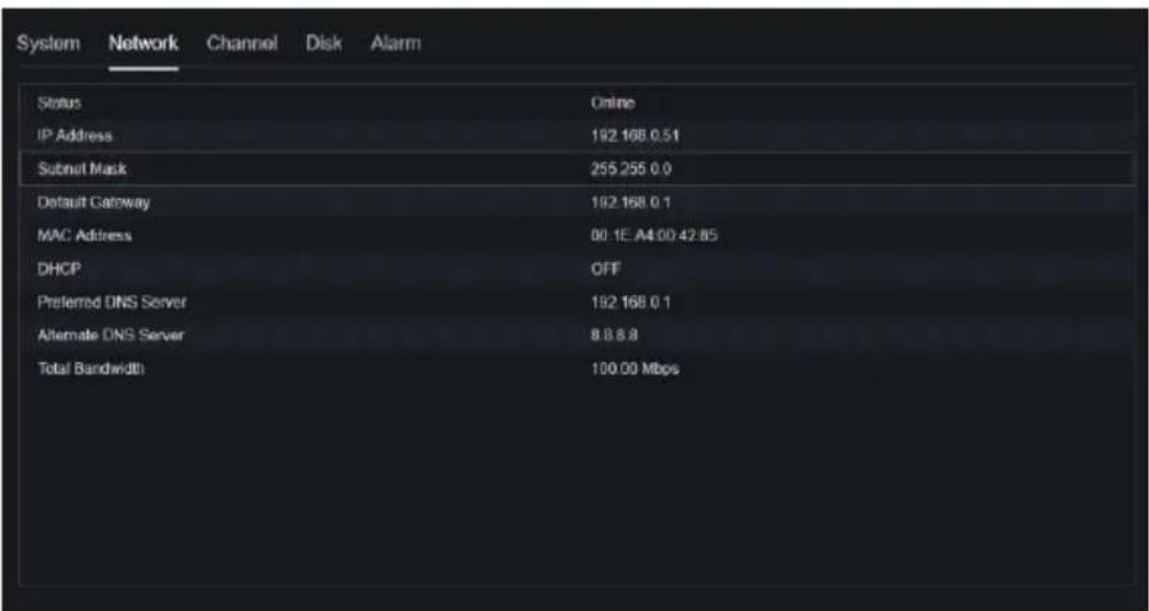
Figure 9-55 Channel
| Channel | Name | Status | Video Format | Resolution | Bitrate(kbps) |
| CH1 | Device | Offline | H265/H265 | 2580*1440/704*576 | 4096/1024 |
| CH2 | Channel12 | Online | H265/H265 | 1920*1080/704*480 | 4096/1024 |
| CH3 | Channel29 | Online | H265/H265 | 1920*1080/704*576 | 4096/1024 |
| CH4 | Device | Online | H264/H264 | 1920*1080/704*576 | 2048/1024 |
Figure 9-56 Disk
| System | Network | Channel | Disk | Alarm | ||
| Disk | Capacity | Used | SN | Disk Model | Status | |
| Disk1 | ZTB | 901GB | WD-WXE1A701JKF4 | WDC WD21PSRX-80/AHTY0 | Normal |
Figure 9-57 Alarm
| System | Network | Channel | Disk | Alarm | |||
| Channel | Name | Mode | Enable | Recording Channel | |||
| Local-1 | Sensor 1 | N/O | On | ||||
| Local-2 | Sensor 2 | N/O | On | ||||
| Local-3 | Sensor 3 | N/O | On | ||||
| Local-4 | Sensor 4 | N/O | On | ||||
| Local->1 | Close |
----End
9.5.2 General
You can set system, date and time, time zone and DST general interface.
Procedure
Step 1 On the System Setting screen, choose System >General to access the general interface, as shown in Figure 9-58.
Figure 9-58 Basic setting interface
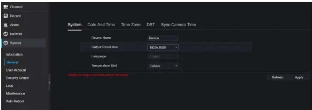
Step 2 Set system.
- Input the device name.
- Choose output resolution from drop list.
- Click to save the system setting.
Step 3 Set date and time.
- Synchronize the time from the NTP server.
- Click NTP Sync button to enable synchronize time. The default value is enabling.
Figure 9-59 System interface
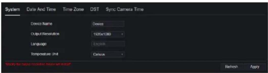
-
Select NTP server, date format and time format from drop list.
-
Click Apply to save date and time setting. The device time will synchronize with NTP server time.
- Set the device time manually, as shown in Figure 9-60.
- Click NTP Sync button to disable synchronize time.
7. Async date and time interface
Figure 9-60 Date and time
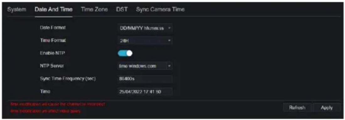
Step 4 Set the time zone.
-
Select date format and time format from the drop-down list.
-
Click to save the device time setting. Click to return to previous setting.
Step 5 Set time zone.
Click Time Zone to enter the time zone setting interface, as shown in Figure 9-61. Time zone setting interface
Figure 9-61 Time zone

Select a time zone from the drop-down list.
Click to save the time zone setting. Click to return to previous setting.
Step 6 Set DST.
- Click DST to enter the DST setting interface, click DST button to enable, as shown in Figure 9-62. The button is disabled by default.
Figure 9-62 DST setting interface
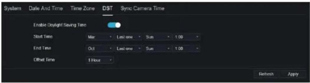
Select a start time from the drop-down list.
Select an end time from the drop-down list.
Select an offset time from the drop-down list.
Figure 9-63 Sync camera time

Enable sync camera time, the cameras of NVR management will be showing the same time. Set the frequency of checks (minimum 10s).
Step 7 Click to save the DST setting. Click to return to previous setting.
----End
9.5.3 User Account
You can create new user accounts to manage the device.
9.5.3.1 Add User
Procedure
Step 1 On the System Setting screen, choose System >User to access the User interface, as shown in Figure 9-64.
Figure 9-64 User interface
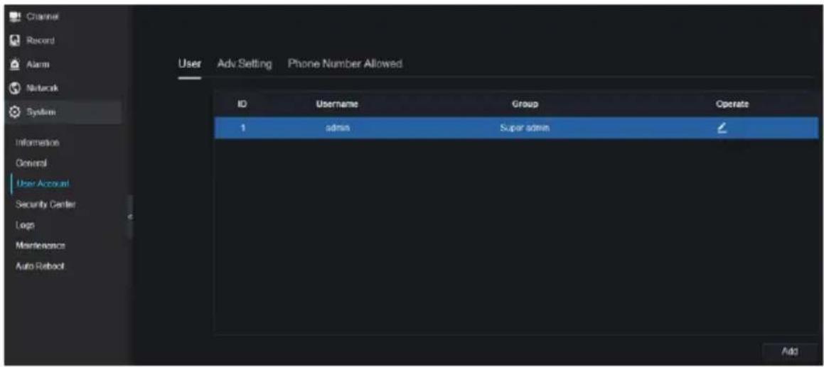
Step 2 Click Add to add a new user, as shown in Figure 9-65.
Figure 9-65 Add user
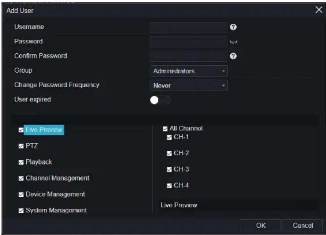
Step 3 Input username, password and confirm password.
Step 4 Select a group and change password reminder from drop-down list.
Step 5 Assign the privilege to the user.
Step 6 Enable the expire date to set the new user's authority time.
Step 7 Select channels to manage.

Step 9 Click to edit user's information.

9.5.3.2 Adv.Setting
Procedure
Step 1 On the System Setting screen, choose System > User > Adv. Setting to access interface, as shown in Figure 9-66.
Figure 9-66 Adv. Setting interface

Step 2 Enable the Password double authentication. If the user want to playback video, he need input another username and password to authenticate.
Step 3 Click to save the device time setting. Click to return to previous setting.
----End
9.5.3.3 App Verification
Add the digital number to white list, when the user logins the cellphone App to manage the NVR, A series of numbers must be added in the whitelist for testing and verification to ensure the security.
Figure 9-67 App Verification

9.5.4 Security Center
9.5.4.1 Password
Procedure
Step 1 On the System Setting screen, choose System >Security Center to access password interface, as shown in Figure 9-68.
Figure 9-68 Password interface

Step 2 Input old password, new password and confirm password.
Step 3 Click Apply to save settings. Click Refresh to return to previous setting.

NOTE
Valid password range [6-32] characters.
At least 2 kinds of numbers, lowercase, uppercase or special character contained.
Only special characters are support ! @#&*+=-%&"'(),/'..;<>?^|\~[]{}.
----End
9.5.4.2 Secure Email
The secure email can receive the verification code of NVR, if user forgot the password accidentally.
Figure 9-69 Secure Email

----End
9.5.4.3 Secure Question
If the user forgets the password and answers the security question correctly, the user can change the password to log in to the NVR..

----End
9.5.5 Logs
9.5.5.1 System Logs
Procedure
Step 1 On the System Setting screen, choose System > Logs to access logs interface, as shown in Figure 9-70.
Figure 9-70 System log interface
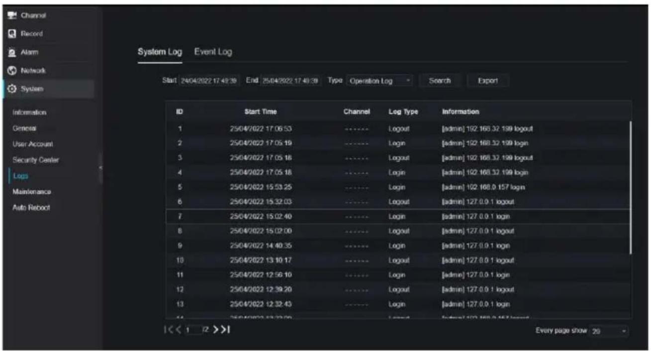
Step 2 Set start and end time from calendar.
Step 3 Select log type from drop-down list.
Step 4 Click Search to acquire log information.
Step 5 Click Export to export the logs.
----End
9.5.5.2 Event
Procedure
Step 1 On the System Setting screen, choose System >Logs > Event to access logs interface, as shown in Figure 9-71.
Figure 9-71 Event log interface

Step 2 Set start and end time from calendar.
Step 3 Select event type from drop-down list.
Step 4 Click Search to acquire log information.
Step 5 Click Export to export the event logs.
----End
9.5.6 Maintenance
Procedure
Step 1 On the System Setting screen, choose System >Maintenance to access maintenance interface, as shown in Figure 9-72.
Figure 9-72 Maintenance interface

Step 2 Click Reboot, the pop-up message will show you, click OK to reboot.
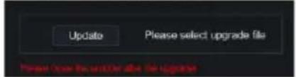
Step 3 Click Update, the message shows "Create Now Before Our Update", choose software from specific location to update.

Step 4 Click Reset, the pop-up message

to reset.
Step 5 If the device is online, and the cloud server has the software, click the Cloud Update, it shows ‘make sure to update’, click OK to update.
----End
9.5.7 Auto Reboot
Procedure
Step 1 On the System Setting screen, choose System > Auto Reboot to access auto restart enable the auto restart, the screen as shown in Figure 9-73.
Figure 9-73 Auto restart

Step 2 Select one type of restart time from drop-down list.
Step 3 Click Apply to save settings. Click Refresh to return to previous setting.
----End
9.6 Local (Supplied for IE Browser)
Set the image download path for snapshot and the record download path for record files in the download configuration interface.

NOTE
This function is only used for IE browser.
Procedure
Step 1 Click Local Download Config in local interface, as shown in Figure 9-74.
Figure 9-74 Local interface
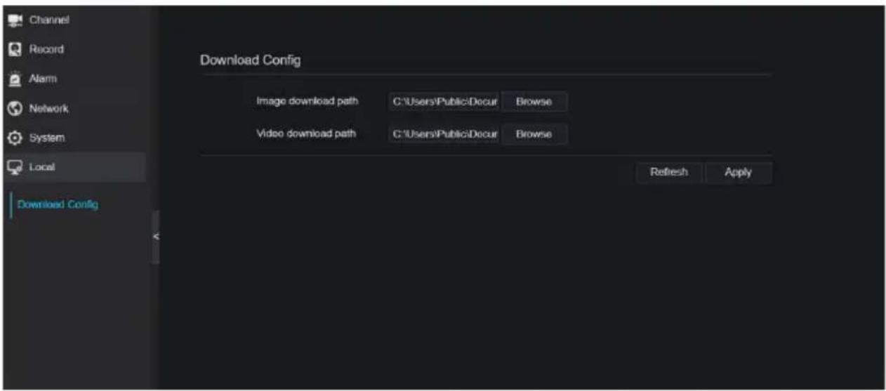
Step 2 Enter the image download path.
Step 3 Enter the record download path.
Step 4 Click Refresh to return the previous settings. Click Apply to save the settings. ----End
10 Disk Compatibility
The hard disks in the following list are tested and certified by our company, if you want to use other hard disks, please consult to our technical staff.
Table 10-1 Disk specification
| Disk Brand | Type | Capacity | Model | Parameter | Verification of Platform |
| WD (Western Digital) | Monitoring level | 3T | WD30EJRX-89G3VY0 | 3000G/5400RPM/64MB/SATA | NVR25 Series /NVR 26 Series /ADR33 Series /ADR36 Series |
| 1T | WD10EJRX-89N74Y0 | 1000G/5400RPM/64MB/SATA | NVR25 Series /NVR 26 Series /ADR33 Series /ADR36 Series | ||
| 4T | WD40PURX-64GVNY0 | 4000G/5400RPM/64MB/SATA | NVR25 Series /NVR 26 Series /ADR33 Series /ADR36 Series | ||
| 2T | WD20EURS-63S48Y0 | NVR25 Series /NVR 26 Series /ADR33 Series /ADR36 Series | |||
| 3T | WD30EURS-63SPKY0 | NVR25 Series /NVR 26 Series /ADR33 Series /ADR36 Series | |||
| 0.5T | WD5000AAKK-001CA0 | NVR25 Series /NVR 26 Series /ADR33 Series /ADR36 Series | |||
| 1T | WD10EZE X-00BN5A0 | 1000G/7200RPM/64MB/SATA | NVR25 Series /NVR 26 Series /ADR33 Series /ADR36 Series | ||
| 4T | WD40EJRX-89T1XY0 | 4000G/5400RPM/64MB/SATA | NVR25 Series /NVR 26 Series /ADR33 Series /ADR36 Series | ||
| 3T | WD30PURX-64P6ZY0 | 3000G/5400RPM/64MB/SATA | NVR25 Series /NVR 26 Series /ADR33 Series /ADR36 Series | ||
| 6T | WD60PURX-64WYOY1 | 6000G/5400RPM/64MB/SATA | NVR25 Series /NVR 26 Series /ADR33 Series /ADR36 Series | ||
| 8T | WD82EJRX-89AD9Y0 | NVR25 Series /NVR 26 Series /ADR33 Series /ADR36 Series | |||
| Desktop | 12T | WD121EJRX-89S5UY0 | 7200RPM/256MB/SATA | NVR25 Series /NVR 26 Series /ADR33 Series /ADR36 Series | |
| Seagate | Monitoring level | 2T | ST2000VX000 | 2000G/5900RPM/64MB/SATA | NVR25 Series /NVR 26 Series /ADR33 Series /ADR36 Series |
| 2T | ST2000VX0 | 2000G/5900RP | NVR25 Series /NVR 26 | ||
| 08 | M/64MB/SATA | Series /ADR33 Series /ADR36 Series | |||
| 4T | ST4000VX0 00 | 4000G/5900RP M/ 64MB/SATA | NVR25 Series /NVR 26 Series /ADR33 Series /ADR36 Series | ||
| 3T | ST3000VX0 00 | 3000G/5900RP M/64MB/SATA | NVR25 Series /NVR 26 Series /ADR33 Series /ADR36 Series | ||
| 4T | ST3000VX0 10 | NVR25 Series /NVR 26 Series /ADR33 Series /ADR36 Series | |||
| 1T | ST31000528 AS | NVR25 Series /NVR 26 Series /ADR33 Series /ADR36 Series | |||
| 6T | ST6000VX0 001 | NVR25 Series /NVR 26 Series /ADR33 Series /ADR36 Series | |||
| 3T | ST3000VX0 10 | 3000G/5900RP M/64MB/SATA | NVR25 Series /NVR 26 Series /ADR33 Series /ADR36 Series | ||
| 8T | ST8000VX0 002 | NVR25 Series /NVR 26 Series /ADR33 Series /ADR36 Series | |||
| Enterprise level | 6T | ST6000VN0 011 | 6000G/7200RP M/128MB/SATA | NVR25 Series /NVR 26 Series /ADR33 Series /ADR36 Series | |
| Toshiba | Monitoring level | 1T | DT01ABA1 00V | 1000G/5400 RPM /32MB/SATA | NVR25 Series /NVR 26 Series /ADR33 Series /ADR36 Series |
| WD (Western Digital) | Monitoring level | 4T/6T/2T/1 T | WD41PSRX | 4000G/5400RP M/64MB/SATA | NVR25 Series /NVR 26Series /NVR 36Series /ADR33Series /ADR36Series |
| 2T | WD20EJRX -89AKWYO | 2000G/5400RP M/64MB/SATA | NVR25 Series /NVR 26Series /NVR 36Series /ADR33Series /ADR36Series | ||
| 10T | NVR25 Series /NVR 26Series /NVR 36Series /ADR33Series /ADR36Series | ||||
| 6T | WD62EJRX -89B2VY0 | NVR 36Series | |||
| 10T | WD102EJR X- 89YN0Y0 | NVR 38 Series /NVR 36Series /ADR33Series | |||
| 18T | WD180EJR X-89AFLY0 | NVR 38 Series /NVR 36Series | |||
| 8T | WD84EJRX -89B2TY0 | NVR 38 Series /NVR 36Series |
Video recording size per channel per hour =bitrate (kbps)*3600/1200/8 (M)
Recording duration = Total hard disk capacity (M) / Video recording size per channel per hour / number channels (H)

- TRADEMARK STATEMENT
- RESPONSIBILITY STATEMENT
- PRIVACY PROTECTION REMINDER
- ABOUT THIS DOCUMENT
- NETWORK SECURITY ADVICE
- REQUIRED MEASURES TO ENSURE BASIC NETWORK SECURITY OF EQUIPMENT
- UPDATE FIRMWARE
- CHANGE YOUR PASSWORD REGULARLY
- MODIFY THE DEFAULT HTTP AND DATA PORTS
- USE HTTPS/SSL ENCRYPTION
- ENABLE IP FILTERING
- CHANGE THE ONVIF PASSWORD
- ONLY FORWARD THE PORTS THAT MUST BE USED
- USE A DIFFERENT USERNAME AND PASSWORD ON THE VIDEO SURVEILLANCE SYSTEM
- RESTRICT THE PERMISSIONS OF THE ORDINARY ACCOUNT
- UPNP
- SNMP
- MULTICAST
- CHECK LOGS
- PHYSICALLY PROTECT YOUR DEVICE
- NETWORK ISOLATION BETWEEN NVR AND IP CAMERAS
- PURPOSE
- SYMBOL CONVENTIONS
- SAFETY INSTRUCTIONS
- REQUIREMENTS
- POWER REQUIREMENT
- IMPORTANT STATEMENT
- CONTENTS
- LEGAL NOTICE ....II
- NETWORK SECURITY ADVICE ....IV
- ABOUT THIS DOCUMENT ...... VII
- SAFETY INSTRUCTIONS......XIII
- CONTENTS......XV
- 1 PREFACE....1
- 2 PRODUCT STRUCTURE .... 5
- 3 INSTALL DEVICE.... 18
- 4 BASIC OPERATIONS 23
- 5 WIZARD.... 31
- 6 QUICK NAVIGATION.... 40
- 7 UI SYSTEM SETTING 98
- 7.5 SYSTEM MANAGEMENT 181
- 8 WEB QUICK START 207
- 9 SYSTEM SETTING.... 246
- 1 PREFACE
- 1.1 PRODUCT DESCRIPTION
- 1.2 PRODUCT FEATURES
- 1.2.1 CLOUD UPGRADE
- 1.2.2 REAL-TIME MONITORING
- 1.2.3 PLAYBACK
- 1.2.4 USER MANAGEMENT
- 1.2.5 STORAGE FUNTION
- 1.2.6 ALARM FUNCTION
- 1.2.7 NETWORK MONITORING
- 1.2.8 SPLIT SCREEN
- 1.2.9 RECORDING FUNCTION
- 1.2.10 BACKUP FUNCTION
- 1.2.11 EXTERNAL DEVICE CONTROL
- 1.2.12 ACCESSIBILITY
- NOTE
- 2 PRODUCT STRUCTURE
- 2.1 FRONT PANEL
- 2.2 BACK PANEL
- 2.3 IMPORTANT NOTES
- 2.4 ABOUT THIS USER MANUAL
- 2.5 INSTALLATION ENVIRONMENT AND PRECAUTIONS
- INSTALLATION ENVIRONMENT
- INSTALLATION PRECAUTIONS
- OTHER PRECAUTIONS
- SERIES OF NVR
- 3 INSTALL DEVICE
- 3.1 PROCESS
- 3.2 UNPACKING INSPECTION
- 3.3 INSTALL HARD DISK
- CAUTION
- 3.3.1 INSTALL ONE OR TWO HARD DISKS
- 3.3.2 INSTALL FOUR HARD DISKS
- 3.3.3 INSTALL EIGHT HARD DISKS
- 4 BASIC OPERATIONS
- 4.1 POWER ON THE DEVICE
- 4.2 ACTIVATION
- 4.3 POWER OFF THE DEVICE
- 4.4 LOGIN TO THE SYSTEM
- 5 WIZARD
- 6 QUICK NAVIGATION
- 6.1 QUICK BAR
- 6.2 REAL TIME VIDEO BAR
- 6.3 PLAYBACK
- 6.3.1 TIME SEARCH
- OPERATION STEPS
- 6.3.2 PICTURE GRID
- 6.3.3 EVENT RECORDING
- 6.3.4 BACKUP LIST
- 6.4 AI RECOGNITION (ONLY FOR SOME MODELS)
- 6.4.1 REAL TIME COMPARISON
- 6.4.1.1 HUMAN FACE
- 6.4.1.2 VEHICLE LICENSE PLATE
- 6.4.1.3 VEHICLE AND FULL BODY
- 6.4.1.4 REAL-TIME BODY TEMPERATURE FILTER
- 6.4.2 SMART SEARCH
- 6.4.2.1 HUMAN FACE SEARCH
- 6.4.2.2 VEHICLE LICENSE PLATE SEARCH
- 6.4.2.3 FULL BODY SEARCH
- 6.4.2.4 VEHICLE SEARCH
- 6.4.2.5 BODY TEMPERATURE SEARCH
- 6.4.2.6 PERSONNEL COUNT
- 6.4.3 ARCHIVES LIBRARY
- 6.4.3.1 FACE LIBRARY
- 6.4.3.2 LICENSE PLATE LIBRARY
- 6.4.4 COMPARISON CONFIGURATION
- 6.4.4.1 FACE COMPARISON
- 6.4.4.2 LICENSE COMPARISON
- 6.4.4.3 TEMPERATURE COMPARISON
- 6.4.4.4 MASK DETECTION CONFIGURATION
- 6.4.4.5 PERSONNEL COUNT CONFIGURATION
- 6.5 ATTENDANCE (ONLY FOR SOME MODELS)
- 6.5.1 ATTENDANCE DATA
- 6.5.2 ATTENDANCE MANAGEMENT
- ATTENDANCE LIBRARY
- ATTENDANCE CHECK POINT SETTINGS
- 6.6 THERMAL TEMPERATURE (ONLY FOR SOME MODELS)
- 6.6.1 TEMPERATURE PARAMETERS
- OPERATION PROCEDURE
- 6.6.2 TEMPERATURE AREA
- DELETE A TEMPERATURE AREA
- 6.6.3 SCHEDULE LINKAGE
- 6.6.4 ADVANCED
- 6.6.5 INQUIRE
- 6.7 CHANNEL INFORMATION
- 6.8 MAIN MENU
- 7 UI SYSTEM SETTING
- 7.1 CHANNEL MANAGEMENT
- 7.1.1 CAMERA
- OPERATION DESCRIPTION
- 7.1.1.1 ADD CAMERA AUTOMATICALLY
- OPERATION METHODS
- 7.1.1.2 ADD CAMERA MANUALLY
- 7.1.1.3 ADD CAMERA BY RSTP
- 7.1.1.4 DELETE CAMERA
- 7.1.1.5 OPERATE CAMERA
- 7.1.2 ENCODE PARAMETER
- 7.1.3 SENSOR SETTING
- UI SYSTEM SETTING USER MANUAL
- 7.1.4 OSD SETTINGS
- 7.1.5 PRIVACY ZONE
- 7.1.6 ROI
- 7.1.7 MICROPHONE (ONLY FOR SOME MODELS)
- 7.1.8 HUMAN THERMOMETER (ONLY FOR SOME MODELS)
- 7.1.8.1 PARAMETER CONFIGURATION
- 7.1.8.3 THERMAL CALIBRATION
- 7.1.9 SMART (ONLY FOR SOME MODELS)
- 7.1.9.1 AI MULTIOBJECT
- 7.1.9.2 LICENSE PLATE RECOGNITION
- 7.1.10 INTELLIGENT TRACKING (ONLY FOR SOME MODELS)
- 7.2 RECORD SETTING
- 7.2.1 RECORD SCHEDULE
- 7.2.2 DISK
- 7.2.3 RAID (ONLY FOR SOME MODELS)
- 7.2.4 STORAGE MODE
- 7.2.5 S.M.A.R.T
- 7.2.5.1 S.M.A.R.T
- 7.2.5.2 WDDA
- 7.2.6 DISK DETECTION
- 7.2.7 CLOUD STORAGE (ONLY FOR SOME MODELS)
- 7.2.8 DISK CALCULATION
- 7.2.9 FTP
- 7.3 ALARM MANAGEMENT
- 7.3.1 GENERAL
- 7.3.1.1 GENERAL
- 7.3.1.2 IO CONTROL PUSH
- 7.3.2 MOTION DETECTION
- AREA
- 7.3.3 VIDEO LOSS
- 7.3.4 INTELLIGENT ANALYSIS (ONLY FOR SOME MODELS)
- END
- FENCE
- 7.3.5 ALARM IN
- 7.3.6 ABNORMAL ALARM
- 7.3.7 ALARM OUT
- 7.3.7.1 ALARM OUT
- 7.3.7.2 CAMERA ALARM OUT
- 7.3.8 LOCAL INTELLIGENT ANALYSIS
- 7.3.8.1 GENERAL
- 7.3.8.2 INTRUSION
- EVENT ACTION
- DETECTION AREA
- SET SCHEDULE
- 7.4 NETWORK MANAGEMENT
- 7.4.1 NETWORK
- 7.4.1.2 PORT
- 7.4.1.3 IPV4CCTV (ONLY FOR SOME MODELS)
- 7.4.1.4 POE (ONLY FOR SOME MODELS)
- 7.4.1.5 WIFI PARAMETER (ONLY FOR SOME MODELS)
- 7.4.1.6 WIFI NETWORK (ONLY FOR SOME MODELS)
- 7.4.2 802.1 X
- 7.4.3 DDNS
- 7.4.4 PORT MAPPING
- 7.4.4.2 NAT PORT
- 7.4.5 EMAIL
- 7.4.6 P2P
- 7.4.7 IP FILTER
- 7.4.8 SNMP
- 7.4.9 3G/4G
- 7.4.10 PPPOE
- 7.4.11 POE STATUS (ONLY FOR SOME MODELS)
- 7.4.12 NETWORK TRAFFIC
- 7.4.13 PLATFORM ACCESS
- 7.5 SYSTEM MANAGEMENT
- 7.5.1 INFORMATION
- 7.5.2 GENERAL
- 7.5.2.1 SYSTEM
- 7.5.2.2 DATE AND TIME
- 7.5.2.3 TIME ZONE
- 7.5.2.4 DST
- 7.5.2.5 SYNC CAMERA TIME
- 7.5.3 USER ACCOUNT
- 7.5.3.1 USER
- 7.5.3.2 ADVANCE SETTING
- 7.5.3.3 APP VERIFICATION
- 7.5.4 SECURITY CENTER
- 7.5.4.1 PASSWORD
- 7.5.4.2 PATTERN UNLOCK
- 7.5.4.3 SECURE EMAIL
- 7.5.4.4 SECURE QUESTION
- 7.5.5 LAYOUT
- 7.5.6 AUXILIARY SCREEN (ONLY FOR SOME MODELS)
- 7.5.7 LOGS
- 7.5.7.1 SYSTEM LOG
- 7.5.7.2 EVENT LOG
- 7.5.8 MAINTENANCE
- 7.5.9 AUTO REBOOT
- 8 WEB QUICK START
- 8.1 ACTIVATION
- 8.2 LOGIN AND LOGOUT
- LOGOUT
- HOMEPAGE LAYOUT
- 8.3 BROWSING VIDEOS
- 8.3.1 BROWSING REAL-TIME VIDEOS
- 8.3.2 LIVE VIDEO
- 8.3.3 CHANNEL OPERATION
- 8.3.4 PTZ CONTROL AND SETTING
- 8.3.5 SENSOR SETTING
- 8.3.6 LAYOUT
- 8.4 PLAYBACK
- 8.4.1 VIDEO PLAYBACK
- 8.5 ALARM SEARCH
- 8.5.1 CHANNEL ALARM
- 8.6 ATTENDANCE (ONLY FOR SOME MODELS)
- 8.6.1 ATTENDANCE DATA
- 8.6.2 ATTENDANCE MANAGEMENT
- 8.7 AI RECOGNITION (ONLY FOR SOME MODELS)
- 8.7.1 REAL TIME COMPARISON
- 8.7.1.1 HUMAN FACE
- 8.7.1.2 VEHICLE LICENSE PLATE
- 8.7.1.3 VEHICLE AND FULL BODY
- 8.7.1.4 REAL TIME BODY TEMPERATURE FILTER
- 8.7.2 SMART SEARCH
- 8.7.2.1 HUMAN FACE SEARCH
- 8.7.2.2 VEHICLE LICENSE PLATE SEARCH
- 8.7.2.3 FULL BODY SEARCH
- 8.7.2.4 VEHICLE SEARCH
- 8.7.2.5 BODY TEMPERATURE SEARCH
- 8.7.2.6 PERSONNEL COUNT
- 8.7.3 ARCHIVES LIBRARY
- 8.7.3.1 FACE LIBRARY
- 8.7.3.2 LICENSE PLATE LIBRARY
- 8.7.4 COMPARISON CONFIGURATION
- 9 SYSTEM SETTING
- 9.1 CHANNEL
- 9.1.1 CAMERA
- 9.1.1.1 PROTOCOL MANAGEMENT
- 9.1.2 ENCODE
- 9.1.3 SENSOR SETTING
- 9.1.4 OSD
- 9.1.5 PRIVACY ZONE
- 9.1.6 ROI
- 9.1.7 MICROPHONE (ONLY FOR SOME MODELS)
- 9.1.8 HUMAN THERMOMETER (ONLY FOR SOME MODELS)
- 9.1.9 SMART (ONLY FOR SOME MODELS)
- 9.1.10 INTELLIGENT TRACKING (ONLY FOR SOME MODELS)
- 9.2 RECORD
- 9.2.1 RECORD SCHEDULE
- PROCEDURE
- 9.2.2 DISK
- 9.2.3 STORAGE MODE
- 9.2.4 RAID (ONLY FOR SOME MODELS)
- 9.2.5 S.M.A.R.T
- 9.2.6 DISK CALCULATION
- 9.2.7 CLOUD STORAGE (ONLY FOR SOME MODELS)
- 9.2.8 FTP
- 9.3 ALARM
- 9.3.1 GENERAL
- 9.3.1.1 GENERAL
- 9.3.1.2 IO CONTROL PUSH
- 9.3.2 MOTION DETECTION
- 9.3.3 VIDEO LOSS
- 9.3.4 INTELLIGENT ANALYSIS (ONLY FOR SOME MODELS)
- 9.3.5 ALARM IN
- 9.3.6 ABNORMAL ALARM
- 9.3.7 ALARM OUT
- 9.4 NETWORK
- 9.4.1 NETWORK
- 9.4.2 DDNS
- 9.4.3 EMAIL
- 9.4.4 PORT MAPPING
- 9.4.4.2 NAT PORT
- 9.4.5 P2P
- 9.4.6 IP FILTER
- 9.4.7 802.1X
- 9.4.8 SNMP
- 9.4.9 WEB MODE
- 9.4.10 3G/4G
- 9.4.11 PPPOE
- 9.4.12 POE STATUS (ONLY FOR SOME MODELS)
- 9.4.13 PLATFORM ACCESS
- 9.5 SYSTEM
- 9.5.1 DEVICE INFORMATION
- 9.5.2 GENERAL
- ASYNC DATE AND TIME INTERFACE
- 9.5.3 USER ACCOUNT
- 9.5.3.1 ADD USER
- 9.5.3.2 ADV.SETTING
- 9.5.3.3 APP VERIFICATION
- 9.5.4 SECURITY CENTER
- 9.5.4.1 PASSWORD
- 9.5.4.2 SECURE EMAIL
- 9.5.4.3 SECURE QUESTION
- 9.5.5 LOGS
- 9.5.5.1 SYSTEM LOGS
- 9.5.5.2 EVENT
- 9.5.6 MAINTENANCE
- 9.5.7 AUTO REBOOT
- 9.6 LOCAL (SUPPLIED FOR IE BROWSER)
- 10 DISK COMPATIBILITY
Brand : D-LINK
Model : DNR-F4216-16P
Category : Video recorder