VABS-P15-S-B6 - Industrial Automation Festo - Free user manual and instructions
Find the device manual for free VABS-P15-S-B6 Festo in PDF.


| Product Type | Vacuum Generator / Valve |
| Model | VABS-P15-S-B6 |
| Brand | Festo |
| Category | Industrial Automation |
| Operating Pressure Range | 2 to 8 bar |
| Vacuum Level | Up to 85% |
| Flow Rate | Approx. 15 l/min at 6 bar |
| Connection Port Size | G1/8 (nominal) |
| Dimensions (L x W x H) | 50 x 30 x 30 mm |
| Weight | Approx. 0.1 kg |
| Material | Aluminum, plastic |
| Operating Temperature | 0°C to 60°C |
| Supply Voltage (if electronic) | Not applicable (pneumatic) |
| Functions | Vacuum generation, switching and monitoring |
| Maintenance | Clean filter regularly; check seals |
| Safety | Operate within specified pressure range; use PPE |
| Spare Parts | Filter elements, seals, O-rings |
| Reparability | Modular design; replaceable components |
| General Information | Part of Festo vacuum range; CE marked |
Frequently Asked Questions - VABS-P15-S-B6 Festo
User questions about VABS-P15-S-B6 Festo
0 question about this device. Answer the ones you know or ask your own.
Ask a new question about this device
Download the instructions for your Industrial Automation in PDF format for free! Find your manual VABS-P15-S-B6 - Festo and take your electronic device back in hand. On this page are published all the documents necessary for the use of your device. VABS-P15-S-B6 by Festo.
USER MANUAL VABS-P15-S-B6 Festo
natural_image
Illustration of a mechanical component with bolts and washers (no text or symbols)FESTO
Festo SE & Co. KG
Ruiter Straße 82
73734 Esslingen
Germany
+49 711 347-0
www.festo.com
Assembly instructions
8148825
2020-12b
[8148827]

Translation of the original instructions
© 2020 all rights reserved to Festo SE & Co. KG
1 Applicable Documents
1
All available documents for the product → www.festo.com/sp.
2 Safety
2.1 Safety instructions
- Only mount the product on components that are in a condition to be safely operated.
- Observe the safety data sheet for the adhesive from the original manufacturer.
2.2 Intended use
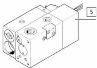
The connection set is intended to create a supply port for measuring the external working pressure 5 in the valve unit.
3 Product range overview
3.1 Scope of delivery
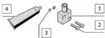
1 Plate (1x)
2 Screw (2x)
3 O-ring (2x)
4 Adhesive (1x)
Fig. 1
3.2 Not in scope of delivery
natural_image
Technical line drawing of a mechanical device with ports and mounting holes (no text or symbols)5 Valve unit (1x) VPCB-...
Fig. 2
4 Function example
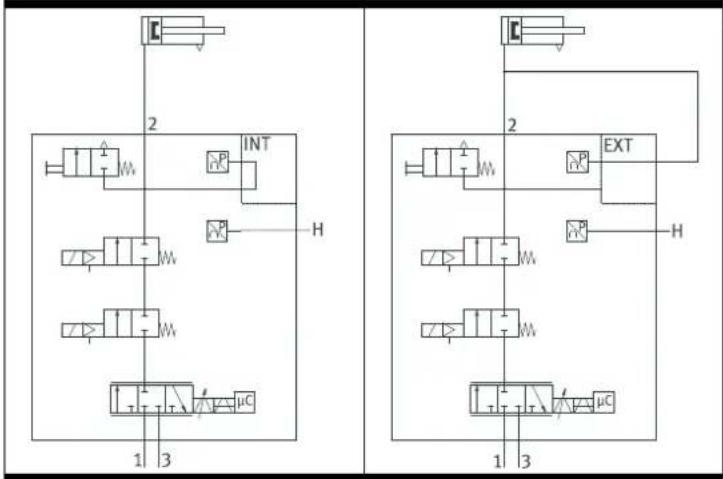
- The working pressure for a valve unit without connection set is measured internally.
- The external working pressure for a valve unit with connection set is measured using the connection set. This requires an external connection from the EXT port to the working port 2. Typical application examples:
- For long distances between the valve and cylinder.
- Use of several cylinders.
Valve unit VPCB
Without connection set VABS with connection set VABS
flowchart
graph TD
    subgraph Left_Circuit
        A["1"] --> B["2"]
        B --> C["3"]
        D["μC"] --> E["4"]
        F["5"] --> G["6"]
        H["7"] --> I["8"]
        J["9"] --> K["10"]
        L["11"] --> M["12"]
        N["13"] --> O["14"]
        P["INT"] --> Q["2"]
        R["EXT"] --> S["3"]
    end
    subgraph Right_Circuit
        T["1"] --> U["2"]
        V["3"] --> W["4"]
        X["5"] --> Y["6"]
        Z["7"] --> AA["8"]
        AB["9"] --> AC["10"]
        AD["11"] --> AE["12"]
        AF["13"] --> AG["14"]
        AH["μC"] --> AI["2"]
        AJ["3"] --> AK["4"]
        AL["5"] --> AM["6"]
        AN["7"] --> AO["8"]
        AP["9"] --> AQ["10"]
        AR["11"] --> AS["12"]
        AT["13"] --> AU["14"]
        AV["EXT"] --> AW["2"]
        AX["EXT"] --> AY["3"]
        AZ["EXT"] --> BA["4"]
        BB["EXT"] --> BC["5"]
        BD["EXT"] --> BE["6"]
        BF["EXT"] --> BG["7"]
        BH["EXT"] --> BI["8"]
        BJ["EXT"] --> BK["9"]
        BL["EXT"] --> BM["10"]
        BN["EXT"] --> BO["11"]
        BP["EXT"] --> BQ["12"]
        BR["EXT"] --> BS["13"]
    end
    style Left_Circuit fill:#f9f,stroke:#333
    style Right_Circuit fill:#bbf,stroke:#333
Tab. 1
5 Assembly
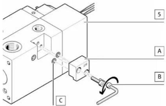
Fig. 3 Demount plate (A)
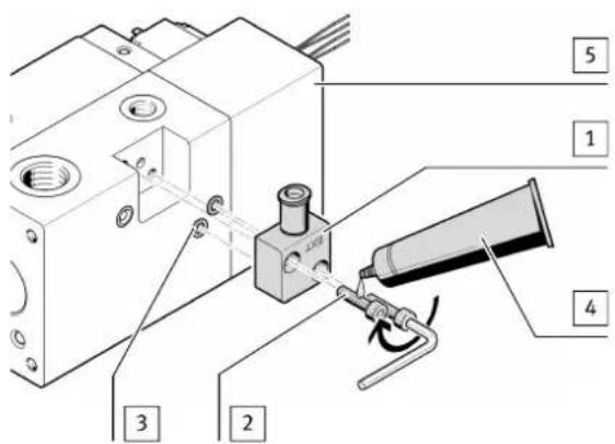
Fig. 4 Mount plate [1]
- Tighten screws 2. Tightening torque: 2.9 Nm ± 10% .
Brand : Festo
Model : VABS-P15-S-B6
Category : Industrial Automation