
PEX2S953LP - Expansion card StarTech.com - Free user manual and instructions
Find the device manual for free PEX2S953LP StarTech.com in PDF.


| Product Type | Expansion Card |
| Model | PEX2S953LP |
| Brand | StarTech.com |
| Interface | PCI Express x1 |
| Ports | 2 x RS232 Serial (DB9 Male) |
| Maximum Baud Rate | 921.6 kbps |
| Chipset | MOSchip MCS9865 |
| Dimensions (L x W x H) | 120 mm x 100 mm x 20 mm |
| Weight | 50 g |
| Power Consumption | 2.5 W (from PCIe slot) |
| Operating Temperature | 0°C to 55°C |
| Humidity Range | 5% to 95% (non-condensing) |
| Form Factor | Low Profile (with included bracket) |
| Supported Operating Systems | Windows, Linux, and macOS |
| Main Functions | Adds two RS232 serial ports for connecting legacy devices, industrial equipment, and point-of-sale systems |
| Compliance | RoHS, FCC, CE, REACH |
| Package Contents | 1x Serial Card, 1x Low Profile Bracket, 1x Driver CD, 1x Quick Installation Guide |
| Maintenance | No regular maintenance required; keep connectors free of dust and debris |
| Safety Instructions | Use anti-static precautions during installation; ensure system is powered off and grounded |
| Spare Parts and Repairability | No user-serviceable parts; card is not repairable; replacement recommended if defective |
Frequently Asked Questions - PEX2S953LP StarTech.com
User questions about PEX2S953LP StarTech.com
0 question about this device. Answer the ones you know or ask your own.
Ask a new question about this device
Download the instructions for your Expansion card in PDF format for free! Find your manual PEX2S953LP - StarTech.com and take your electronic device back in hand. On this page are published all the documents necessary for the use of your device. PEX2S953LP by StarTech.com.
USER MANUAL PEX2S953LP StarTech.com
2-Port PCI Express Serial Card with 16950 UART - Low-Profile
Product Diagram (PEX2S953LP)
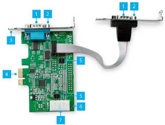
| Port Function | ||
| 1 | Serial Port | Used to connect Serial Devices |
| 2 | Screws | Used to attach the Serial Port to the BracketUsed to secure a Serial Cable to the Serial Port |
| 3 | Bracket | Used to attach the Card to the Computer |
| 4 | PCI Express Bus Connector | Used to connect the PCI Express Serial Card to the Computer's Motherboard |
| 5 | Jumper | Used to configure Serial Port power settings |
| 6 | Printed Circuit Board | Components such as Jumpers are located on the Board |
7 LP4 Power Connector • Used to connect a Power Source
Requirements
• PCIe Slot
- Needle-Nose Pliers
For the latest requirements and full manual, please visit www.startech.com/PEX2S953LP.
Installation
WARNING!
PCI Express Serial Cards can be severely damaged by static electricity. Make sure that you are properly grounded before you open your Computer Case or touch the PCI Express Serial Card. You should wear an Anti-Static Strap when you install any computer component. If an Anti-Static Strap isn't available, discharge any built-up static electricity by touching a large Grounded Metal Surface for several seconds. Only handle the PCI Express Serial Card by its edges and don't touch the gold connectors.
Jumper Configuration
Note: Jumper configuration is a requirement when connecting Serial Devices that require power through a Serial Port.
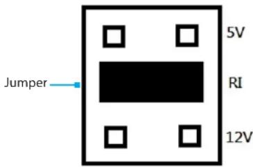
This Jumper can be moved into one of three different positions in order to set the power output voltage for the Serial Ports. The default setting for the Jumpers is RI, which is the setting for no power. The Jumper can be moved to one of the other two settings for 5V or 12V of power. To configure the Jumper, complete the following:
- Locate the Jumper for Port One. Port One is located on the right hand side, labeled as COM1 on the Printed Circuit Board. The Jumper is labeled as J1 on the Printed Circuit Board.
- Carefully remove the Jumper. Lift the Jumper straight up and off of the PCI Express Serial Card.
Note: Always hold the Card by the edges.
- Determine the power setting that is required for Port One.
- Position the Jumper over the set of Pins that correspond with the desired Serial Port Power Setting. See Figure 1 to determine where the Jumper should be positioned.
- Push the Jumper straight down and into place.
Note: Push the Jumper all the way into position for proper contact.
- Repeat these steps to configure the Jumper for Port 2. This Jumper will be labeled as J7 on the Printed Circuit Board.
Figure 1
Hardware Installation
Note: This PCI Express Serial Card is specially designed to allow for power output from the ninth pin of the Serial Connector(s) for devices that support power over Serial. This card allows users to set each Serial Port to 5V, 12V, or RI (no power). Users can also choose to draw the necessary power from the Computer's Power Supply by connecting to the LP4 Power Connector.
- Turn off the power to your Computer.
- Unplug your Computer's Power Cord.
- Remove your Computer's Cover.
- Remove the corresponding Full-Height or Low-Profile Slot Brackets from an available PCIe Slot.
FCC Compliance Statement
This equipment has been tested and found to comply with the limits for a Class B digital device, pursuant to part 15 of the FCC Rules. These limits are designed to provide reasonable protection against harmful interference in a residential installation. This equipment generates, uses and can radiate radio frequency energy and, if not installed and used in accordance with the instructions, may cause harmful interference to radio communications. However, there is no guarantee that interference will not occur in a particular installation. If this equipment does cause harmful interference to radio or television reception, which can be determined by turning the equipment off and on, the user is encouraged to try to correct the interference by one or more of the following measures:
- Connect the equipment into an outlet on a circuit different from that to which the receiver is connected.
- Consult the dealer or an experienced radio/TV technician for help
This device complies with part 15 of the FCC Rules. Operation is subject to the following two conditions:
(1) This device may not cause harmful interference, and (2) this device must accept any interference received, including interference that may cause undesired operation. Changes or modifications not expressly approved by StarTech.com could void the user's authority to operate the equipment.
Industry Canada Statement
This Class B digital apparatus complies with Canadian ICES-003.
This device complies with Industry Canada licence-exempt RSS standard(s). Operation is subject to the following two conditions:
(1) This device may not cause interference, and (2) This device must accept any interference, including interference that may
cause undesired operation of the device.
This equipment complies with IC RSS-102 radiation exposure limit set forth for an uncontrolled environment. This equipment should be installed and operated with minimum distance 0.5cm between the radiator and your body.
Use of Trademarks, Registered Trademarks, and other Protected Names and Symbols
This manual may make reference to trademarks, registered trademarks, and other protected names and/or symbols of third-party companies not related in any way to StarTech.com. Where they occur these references are for illustrative purposes only and do not represent an endorsement of a product or service by StarTech.com, or an endorsement of the product(s) to which this manual applies by the third-party company in question. StarTech.com hereby acknowledges that all trademarks, registered trademarks, service marks, and other protected names and/or symbols contained in this manual and related documents are the property of their respective holders.
- (Full-Profile installations) Remove the four Screws from the Low-Profile Brackets, using Needle-Nose Pliers. Insert the Serial Ports into the Full-Profile Bracket, with the Serial Port that is connected via Ribbon Cable on the left-hand side. Insert and fasten all four of the Screws, using Needle-Nose Pliers.
- To install the Card, carefully align the Card's Bus Connector with the selected PCIe Slot on the Motherboard. Push the Card down firmly to ensure the Card is properly seated into the PCIe Slot.
- (Optional): Connect the LP4 Power Connector Cable from the Computer's Power Supply to the LP4 Power Connector Port on the Card.
- Replace the Slot Bracket's Holding Screw to secure the Card.
- Replace the Computer's Cover and reconnect the Power Cord.
- Download the latest Drivers. See Driver Installation for more details.
Driver Installation
You can download the latest Drivers from the StarTech.com website: www.startech.com/PEX2S953LP
Navigate to the Support Page to locate the Drivers. Follow the instructions included with the Driver Files.
Warranty Information
This product is backed by a lifetime warranty.
For further information on product warranty terms and conditions, please refer to www.startech.com/warranty.
Limitation of Liability
In no event shall the liability of StarTech.com Ltd. and StarTech.com USA LLP (or their officers, directors, employees or agents) for any damages (whether direct or indirect, special, punitive, incidental, consequential, or otherwise), loss of profits, loss of business, or any pecuniary loss, arising out of or related to the use of the product exceed the actual price paid for the product. Some states do not allow the exclusion or limitation of incidental or consequential damages. If such laws apply, the limitations or exclusions contained in this statement may not apply to you.
Safety Measures
+ If product has an exposed circuit board, do not touch the product under power.
Mesures de sécurité
Brand : StarTech.com
Model : PEX2S953LP
Category : Expansion card