
58336 - Milling machine TORO - Free user manual and instructions
Find the device manual for free 58336 TORO in PDF.


| Product Type | Tiller (Rotary Cultivator) |
| Brand | Toro |
| Model | 58336 |
| Engine Type | 4-cycle, air-cooled, Briggs & Stratton |
| Engine Power | 2 hp (1.5 kW) or 4 hp (3 kW) |
| Displacement | 6.65 cu in (108 cc) for 2 hp; 11.39 cu in for 4 hp |
| Fuel Tank Capacity | 1 quart (0.946 L) for 2 hp; 2 quarts (1.88 L) for 4 hp |
| Crankcase Oil Capacity | 20 ounces (0.591 L) |
| Clutch System | V-belt with pivoting idler pulley |
| Tine Type | 8 double-ended heat-treated slasher-style blades |
| Width of Swath | Adjustable from 11 to 22 inches (0.305 to 0.559 m) |
| Wheel Size | 8 x 1.75 semi-pneumatic tires |
| Dimensions (Operating) | 43 in L x 22 in W x 37 in H (1.09 m x 0.56 m x 0.94 m) |
| Dimensions (Storage) | 29 in L x 22 in W x 26 in H (0.74 m x 0.56 m x 0.66 m) |
| Dry Weight | 70 lb (31.8 kg) for 2 hp; 73 lb (33.1 kg) for 4 hp |
| Drag Bar | Steel U-formed, manually pivoted 90° |
| Handle Material | 1 in (25 mm) steel tubing, zinc plated, foldable |
| Chain Drive Case | Die-cast aluminum, pre-filled with oil |
| Maintenance Interval (Oil Change) | First 2 hours, then every 25 hours |
| Warranty | 1 year residential, 45 days commercial |
Frequently Asked Questions - 58336 TORO
User questions about 58336 TORO
0 question about this device. Answer the ones you know or ask your own.
Ask a new question about this device
Download the instructions for your Milling machine in PDF format for free! Find your manual 58336 - TORO and take your electronic device back in hand. On this page are published all the documents necessary for the use of your device. 58336 by TORO.
USER MANUAL 58336 TORO
To assure maximum safety, optimum performance, and to gain knowledge of the product, it is essential that you or any other operator of the tiller read and understand the contents of this manual before the engine is ever started. Pay particular attention to the SAFETY INSTRUCTIONS highlighted by this safety alert symbol —

The symbol means CAUTION, WARNING or DANGER — personal safety instruction. Failure to comply with the instruction may result in personal injury.

FOREWORD
The TORO Tiller has advanced concepts in engineering, design, and safety and if maintained properly, the product will be reliable.
Since the tiller is a high-quality product, TORO is concerned about the future use of the tiller and safety of the user. Therefore, read this manual to familiarize yourself with the safety instructions and the product before operating the tiller. The six major sections of the manual are:
- Safety Instructions
- Setting Up Instructions
- Preparation Before Starting
- Operating Instructions
- Maintenance
- Trouble Shooting
Note that safety, mechanical, and some general information in the manual is emphasized. The words CAUTION, WARNING, DANGER, IMPORTANT, and NOTE are used to classify the information. CAUTION, WARNING, and DANGER identify safety related information; and NOTE identifies general information worthy of special attention.
OPTIONAL SPARK ARRESTER
In some areas there are local, state or federal regulations requiring that a spark arrester be used on the engine of this tiller. If a spark arrester is required, order the following parts from your local Briggs-Stratton dealer:
1 392190 Spark Arrester Assembly
These parts are approved by the United States Department of Agriculture and Forestry. The approval number for the exhaust system is 391911.
When tiller is used or operated on any California forest, brush or grass covered land, a working order spark arrester must be attached to muffler. If not, the operator is violating state law, Section 4442 Public Resources Code.
If help — concerning set-up, operation, maintenance, or safety — is ever needed, contact the local Authorized TORO Service Dealer or Distributor. Refer to the "Yellow Pages" for assistance. In addition to skilled service technicians, the dealer and distributor have other TORO products, as well as factory approved accessories and replacement parts. Keep your Toro Tiller all TORO. Buy genuine TORO replacement parts and accessories.
TABLE OF CONTENTS
| Page | Page | |
| Safety Instructions | 3 | Maintenance 13 |
| Before Operating | 3 | Servicing Air Cleaner 13 |
| While Operating | 3 | Replacing Spark Plug 13 |
| Maintaining Tiller | 3 | Changing Crankcase Oil 14 |
| Specifications | 4 | Checking Oil Level in Chain Case 14 |
| Uncartoning and Loose Parts | 5 | Filling Chain Drive Case 15 |
| Setting Up Instructions | 5 | Lubricating Wheels and Idler Pulley 15 |
| Know Your Tiller | 6 | Draining Gasoline From Fuel Tank 16 |
| Preparation Before Starting | 7 | Cleaning Engine Blower Housing 16 |
| Fill Crankcase With Oil | 7 | Adjusting Belt Tension 16 |
| Fill Fuel Tank With Gasoline | 7 | Replacing Drive Belt 17 |
| Chain Drive Case | 8 | Carburetor Adjustment 17 |
| Controls | 8 | Initial Adjustment 17 |
| Starting and Stopping Instructions | 9 | Final Adjustment 17 |
| Operating Instructions | 10 | Preparing Tiller For Storage 18 |
| Break-In | 10 | Trouble Shooting 19 |
| Drag Stake | 10 | Identification and Ordering 21 |
| Adjusting Wheel | 11 | Model and Serial Numbers 21 |
| Changing Width of Swath | 11 | Maintenance Record 22 |
| Using the Tiller | 12 | The Toro Promise Back Cover |
SAFETY INSTRUCTIONS


natural_image
Black triangular warning symbol with exclamation mark (no text or numbers)This safety alert symbol means CAUTION, WARNING, or DANGER — “personal safety instruction”. Read and understand the instruction, because it has to do with safety. Failure to comply with the insult in personal injury.
The following "Instructions for Safe Tilling" are suggested by The Toro Company. Failure to operate the tiller in accordance with these Safety Instructions MAY RESULT IN PERSONAL INJURY.
BEFORE OPERATING
-
Read and understand the contents of this manual before starting and operating the tiller. Become familiar with all controls and know how to stop tiller quickly. NEVER ALLOW CHILDREN TO OPERATE TILLER.
-
Keep everyone, especially children and pets, away from the area of operation. Remove glass, metal objects, sticks, stones, wire and any other debris that might get caught in or possibly be thrown by the tines.
-
Keep all shields and safety devices in place. If shield, safety device or decal is defective or damaged, repair or replace it before operation is commenced. Also tighten any loose nuts, bolts and screws.
-
Wear long pants and substantial shoes while using the tiller. Do not operate tiller while barefoot, wearing sandals, tennis shoes, sneakers or shorts.
-
Fill fuel tank with gasoline before starting the engine. Avoid spilling any gasoline. Since gasoline is highly flammable, handle it carefully.
A. Use an approved gasoline container.
B. Fill tiller fuel tank outdoors when engine is cool. Engine must not be running to prevent a potential hazard.
C. Wipe up any gasoline that may have spilled, and install gasoline container cap and tiller fuel tank cap before starting the engine.
WHILE OPERATING
- Open doors if engine will be run in the garage, because exhaust fumes are dangerous and could possibly be deadly. Do not run engine indoors.
- Do not operate the tiller if someone is near the area to be tilled.
- Tilling the soil demands attention. Always maintain secure footing, balance and control.
- Till the soil when it is dry, because wet or sticky soil can cause mechanical damage.
- Keep face, hands, feet and any other part of the body or clothing away from concealed or exposed rotating parts such as the tines, belts and pulleys. Stay behind the handles and away from the tines while operating the tiller.
- Release clutch control, shut engine off and wait for all parts to stop before removing any obstruction from the tines.
- If a solid object is hit by the tines or tines get plugged, release clutch control and shut engine off. Remove high tension wire from spark plug; then check for possible damage, an obstruction or loose parts. Make all repairs before using the tiller again.
- Before leaving the operator's position — behind handles — release clutch control and shut engine off. Pull high tension wire off spark plug to prevent possibility of accidental starting.
- Do not touch the engine while it is running or soon after it is stopped, because the engine may be hot enough to cause a burn.
MAINTAINING TILLER
- Before performing any maintenance or servicing the tiller, shut engine off and pull high tension wire off spark plug to prevent possibility of accidental starting.
- Perform only those maintenance instructions described in this manual. If major repairs are ever needed or assistance is desired, contact an Authorized TORO Service Dealer.
- Keep tiller in safe operating condition by having nuts, bolts, and screws tight.
SAFETY INSTRUCTIONS
- To reduce potential fire hazard, make sure engine and tiller chassis is free of excessive grease, vegetation, dirt and other foreign matter.
- Do not overspeed the engine by changing governor settings. Recommended engine speed is
3000 rpm. To assure safety and accuracy, have an Authorized TORO Service Dealer check maximum engine speed (3200 rpm) with a tachometer.
SPECIFICATIONS
Engine: 2 hp (1.5 kw) Briggs & Stratton engine, four cycle, air cooled with output of 2 hp (1.5 kw) at 3600 rpm and 3.15 ft-lb (4.27 N'm) of torque at 3000 rpm. Displacement is 6.65 cubic inches (10.89 cc). Fuel tank capacity is 1 quart (.946 l) of gasoline, and crankcase capacity is 20 ounces (.591 l) of oil.
4 hp (3 kw) Briggs & Stratton engine, four cycle, air cooled, with output of 4 hp (3 kw) at 3600 rpm and 6.1 ft-lb (8.27 N'm) of torque at 2700 rpm. Displacement is 11.39 cubic inches. Fuel tank capacity is 2 quarts (1.88 l) of gasoline, and crank-case capacity is 20 ounces (.591 l) of oil.
Clutch: Clutching system has a tight/slack V-belt controlled by a pivoting idler pulley.
Tines: 8 double-ended heat-treated slasher-style blades.
Chain Drive: All heavy duty ball and roller bearings.
Controls: Throttle control mounted on engine has three positions: FAST, SLOW, and STOP. Drive clutch control is mounted on the right handle. By squeezing the control against handle, pivoting idler pulley is pulled against a V-belt; thus, tine engagement results. When desired, a thumb-actuated locking pin may be used to maintain the engagement.
Wheels: Polypropylene wheels with sintered metal wheel bushings.
Tires: Two 8 x 1.75 semi-pneumatic tires with diamond tread.
Chassis/Chain Case: 1/8 inch (3 mm) wall, 2 piece bolt-together die cast aluminum to provide enclosure for chain drive and mounting for engine, lower handle column, pivot blocks for drag or draw bar, and forward mounting for shroud.
Handles: 1 inch (25 mm) diameter x 16 gauge (1.65 mm) steel tubing, welded to a control bracket. Handles are zinc plated and have vinyl handle grips. Handles fold down to a storage position.
Drag Bar: a 1/4 inch x 1 inch (6 mm x 25 mm) steel U-formed drag bar manually pivoted to working and storage position. The drag bar is free swinging, approx. 90°.
Width of Swath: Width of swath is adjustable from 11 to 22 inches (.305 m to .559 m).
Overall Dimensions: Handles in operating position - 43 inches (1.092 m) long, 22 inches (.559 m) wide, 37 inches (.940 m) high. Handles folded in storage position - 29 inches (.737 m) long, 22 inches (.559 m) wide, 26 inches (.66 m) high.
Weight: 2 hp (1.5 kw) – dry weight 70 lb. (31.75Kg) (approx.); 4 hp (3 kw) – dry weight 73 lb. (33.11Kg) (approx.).
Parts and Accessories: At the time of manufacture, the tiller was made from quality parts and is as safe as normal tiller design allows. To assure safety and optimum performance, purchase only genuine TORO replacement parts and accessories to keep the Toro Tiller all TORO. NEVER USE "WILL-FIT" REPLACEMENT PARTS AND ACCESSORIES. The TORO label assures you it is genuine.

LOOSE PARTS
NOTE: Carefully remove all loose parts and packing inserts from carton. Cut end of carton nearest the wheels and ROLL tiller out of carton to avoid any unnecessary lifting. Use chart below to make sure that all parts have been shipped.
| Description | Quantity | Use |
| Owner's Manual | 1 | Read Owner's Manual before operating tiller. |
| Registration Card | 1 | Fill out and send to The TORO Company. |
| Oil Tube | 1 | Filling crankcase with oil. |
SETTING UP INSTRUCTIONS
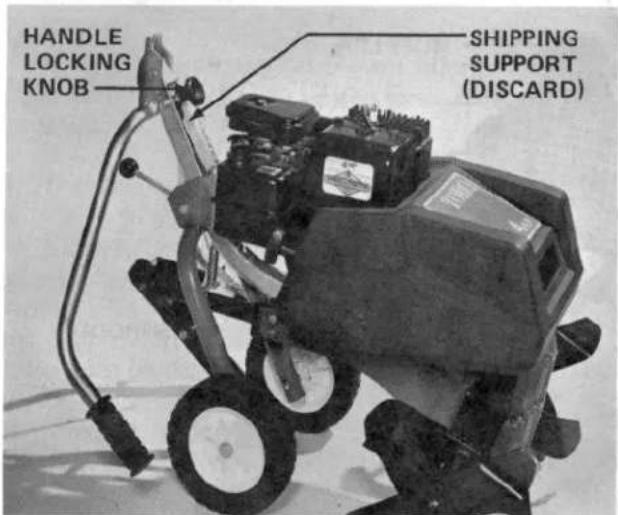
Figure 1 Tiller-Chain Drive out of carton
Your new Chain Drive Tiller comes completely assembled from the factory. However, the handle must be rotated into the operating position.
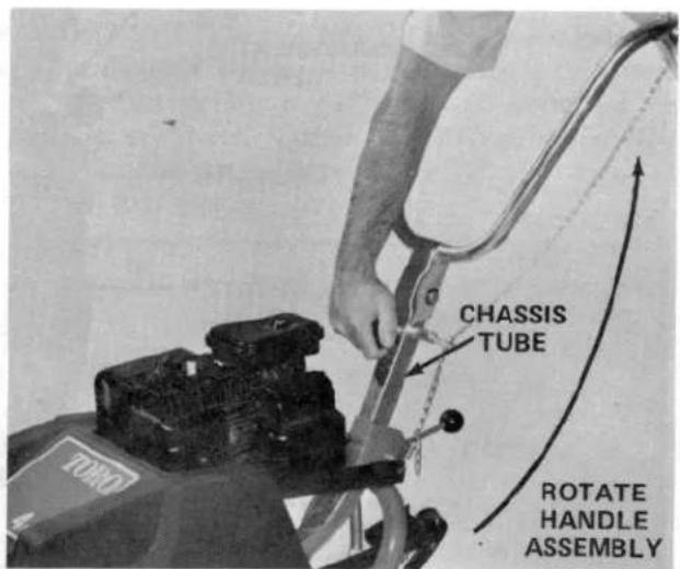
Figure 2 Handles Rotated to Operating Position
To rotate handles:
- Remove handle locking knob.
- Discard shipping support (Fig 1).
- Replace handle knob and rotate handle upward so that the slot in the handle assembly is under the handle locking knob.
- Secure the handle assembly to the chassis tube by tightening handle locking knob securely.
KNOW YOUR TILLER
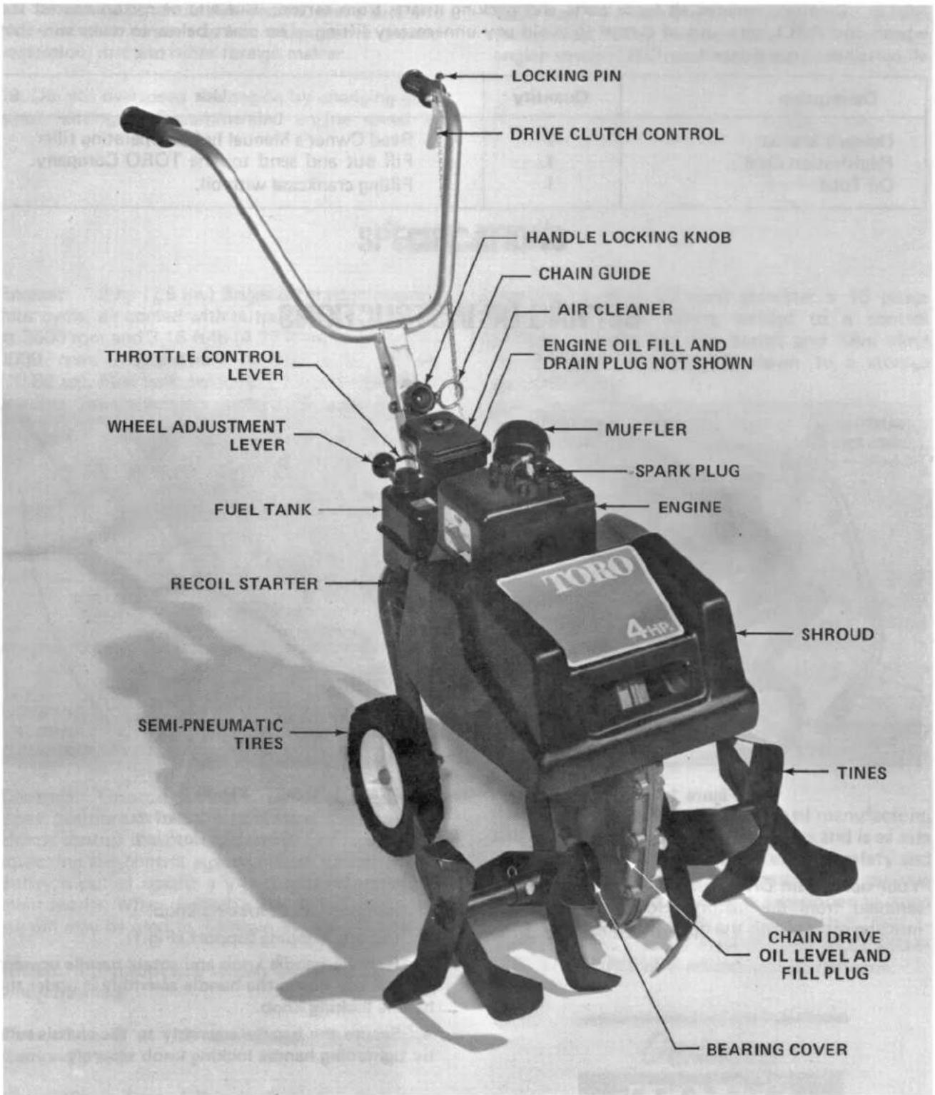
Figure 3
LEFT and RIGHT indicate the left and right sides of the tiller when facing toward the front of the machine from the operating position.
PREPARATION BEFORE STARTING
FILL CRANKCASE WITH OIL
Tools Required: Pliers, Clean Rag, Funnel and Oil Tube (provided)
IMPORTANT: The tiller is shipped from the factory without oil in the crankcase. Before starting engine, crankcase must be filled to the proper level with recommended oil.
IMPORTANT: Check level of oil every 5 operating hours or each time tiller is used. Initially, change oil after the first 2 hours of operation; thereafter, under normal conditions, change oil after every 25 hours of operation. Change oil more frequently when engine is operated in only dusty or dirty conditions.
- Move tiller to a level surface to assure accurate oil level reading.
- Clean the area around the oil filler plug so foreign matter cannot enter filler hole when plug is removed.
-
Remove filler plug from crankcase (Fig. 4).
-
Slowly, pour approximately 20 ounces (.591 l) of oil into crankcase using provided oil tube with funnel (Fig. 4). The Briggs & Stratton engine uses any high quality detergent oil having the American Petroleum Institute — API — “service classification” MS, SC, SD, or SE. Oil viscosity — weight — must be selected according to the season’s ambient temperature.
A. Summer (over 40°F, 4°C) Use S.A.E. 30 or 10W-40 oil.
B. Winter (below 40^ F, 4^ C) — Use S.A.E. 10W or 5W-30 oil.

Figure 4 Filling Crankcase With Oil
- After crankcase is filled with oil, rock the tiller gently to release any air that may be trapped in the crankcase. If level of oil drops, add enough to bring it up to the point of overflowing.
- Install filler plug into opening in crankcase. Wipe up any oil that may have spilled.
FILL FUEL TANK WITH GASOLINE
Tools Required: Clean Rag and Funnel with Filter
Always use clean, fresh gasoline. If gasoline is allowed to stand it will form gum-like varnish deposits in the carburetor, fuel line, and fuel tank. Such deposits cause starting problems and poor engine operation.
IMPORTANT: Do not mix oil w/gasoline because engine damage and poor performance may result. Do not use premium gas, gasohol, white gas or gasoline additives. Either leaded-regular or low lead gasoline is acceptable to fill the 2 quart (1.88 l) fuel tank.

DANGER
Because gasoline is flammable, caution must be used when storing or handling it. Do not fill fuel tank while engine is running, hot or when machine is in an enclosed area. Vapors may build up and be ignited by a spark or flame source many feet away. DO NOT SMOKE while filling the fuel tank to prevent the possibility of an explosion. Always fill fuel tank outside and wipe up any spilled gasoline before starting engine. Use a funnel or spout to prevent spilling gasoline, and fill tank to about 1/2 inch (12.7 mm) below the filler neck. Store gasoline in a clean safety-approved container and keep the cap in place on the container. Keep gasoline in a cool, well-ventilated place; never in an enclosed area such as a hot storage shed. To assure volatility, do not buy more than a 30 day supply of gasoline. Gasoline is a fuel for internal combustion engines; therefore, do not use it for any other purpose. Since many children like the smell of gas, keep it out of their reach because the fumes are explosive and dangerous to inhale.
PREPARATION BEFORE STARTING
- Clean area around the fuel tank cap so foreign matter cannot enter the tank when cap is removed.
- Remove cap from fuel tank and fill tank with leaded regular or low lead gasoline. Then install fuel tank cap.
- Wipe up any gasoline that may have spilled while tank was being filled.
CHAIN DRIVE CASE
The chain drive case comes filled with oil. It is not necessary to fill chain drive case unless shipping carton shows evidence that oil has leaked out: Refer to Filling Chain Drive Case, page 17.
Under normal operating conditions the chain drive case need only be checked once a year to make sure oil level is maintained. However, if there is evidence of oil leaking from the chain case or bearings, check oil level more frequently. If oil leaks persist contact your nearest Authorized TORO Service Dealer.
CONTROLS
Drive Clutch Control (Fig. 5) — Clutch control is mounted near the left handle grip. By squeezing control against handle, pivoting idler pulley is pulled against a V-belt; thus, forward tine engagement results. To maintain tine engagement, squeeze clutch control continuously or depress locking pin and release control against pin. Squeeze clutch control against handle, which will disengage locking pin, and allow control to release: Tines and forward movement will stop.
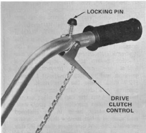
Figure 5
Locking Pin and
Drive Clutch Control
Throttle Lever (Fig. 6) — Throttle lever is mounted on the right side of the engine, and it has three positions — FAST, SLOW, and STOP.
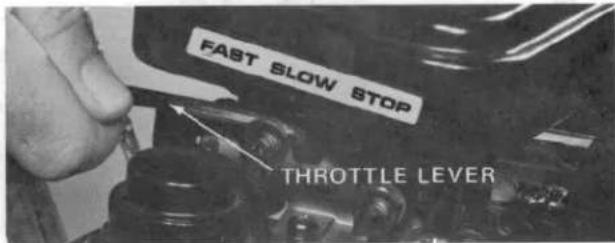
Figure 6
Throttle Lever
Choke Valve (Fig. 7) — Choke valve is located on the carburetor and is used for starting a cold engine; The choke valve has two positions:
A. Full choke - choke valve fully extended.
B. No choke - choke valve fully pushed in.

Figure 7
Full Choke Position
CONTROLS
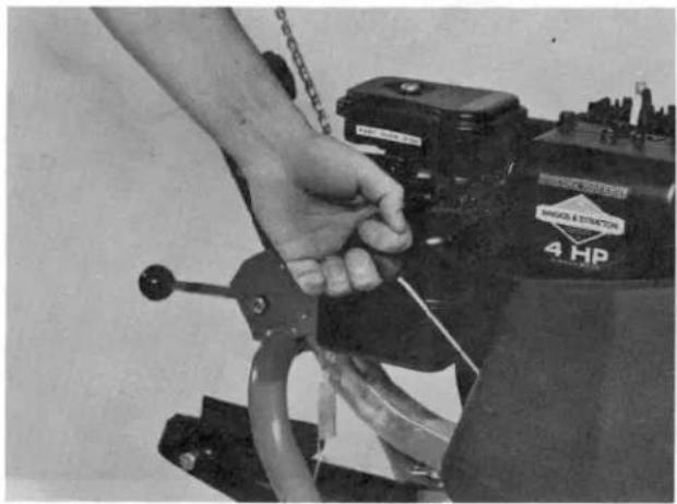
Recoil Starter (Fig. 8) — Pull recoil starter handle to start engine.
natural_image
Close-up of a hand gripping a cable with a battery labeled '4 HP' (no readable text or symbols beyond label)Figure 8 Recoil Starter
Wheel Adjusting Lever (Fig. 9) — The wheels on the tiller can be raised or lowered to govern the forward speed of the tiller and depth of tilling.
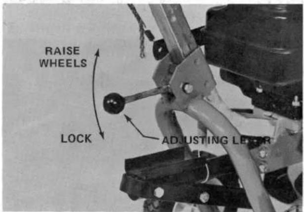
Figure 9 Adjusting Wheels
STARTING AND STOPPING INSTRUCTIONS
NOTE: Make sure the high tension wire is installed on the spark plug before attempting to start engine.
- Check drive clutch control to make sure it is fully released (Fig. 10).

Figure 10 Clutch Control Released
- Pull Throttle lever out to the FAST position (Fig. 11).

Figure 11 Throttle in Fast Position
STARTING AND STOPPING INSTRUCTIONS
- Pull the choke valve out (Fig. 12) when starting a cold engine. However, a warm or hot engine usually does not require any choking. When starting a warm engine, move throttle lever to the FAST position.

Figure 12 Full Choke Position
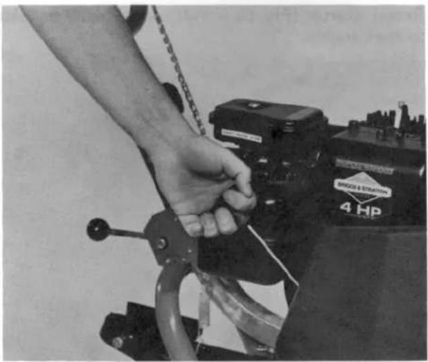
- Pull recoil starter handle out until positive engagement results: Then pull handle vigorously to start engine (Fig. 13). When engine starts, regulate choke and throttle to keep the engine running. As engine gets warm move choke inward fully (no-choke position).
natural_image
Close-up of a hand operating a 4 HP industrial machine tool (no visible text or symbols)Figure 13 Recoil Starter
- To stop engine, during operation, release (disengage) drive clutch control and move throttle lever to the stop position.

CAUTION
To stop engine quickly in an emergency, release (disengage) drive clutch control and move throttle lever to the STOP position.
OPERATING INSTRUCTIONS
BREAK-IN
The engine requires no special break-in other than changing crankcase oil after the first two hours of operation. Operate the tines to make sure that drive system is functioning correctly. After the first five hours of operation, check condition of belt and check for possible loosening of any nuts, bolts, and screws.
DRAG STAKE
Drag Stake (Fig. 14 and 15) — When the drag stake engages the soil, it forces the tines into the soil and eases operator effort in controlling forward advance and overall control of the tiller. When tiller is pulled backward, drag stake will pivot forward so movement is not adversely affected.
OPERATING INSTRUCTIONS
Tilling (Engaged) Position:
- Rotate locking channel so that the drag stake is free to rotate down to tilling position (Fig. 14).

Figure 14 Tilling Position
Transport Position:
- After tilling, move drag stake forward and rotate locking channel to hold drag stake in transport position (Fig. 15).

Figure 15 Storage and Transport Position
ADJUSTING WHEELS
Wheels on the tiller can be raised or lowered to govern forward speed of the tiller and depth of tilling. To adjust, proceed as follows:
- Move adjusting lever upward (Fig. 16). Raise or lower the wheels to the desired position, then

Figure 16 Adjusting Wheels
lock wheels in position by depressing adjusting lever. Ground conditions vary greatly, and you will have to experiment with degree of adjustment until you get satisfactory results.
-
Wheels will ride on the ground once tilling begins.
-
After tilling, wheels can be adjusted again for transporting tiller.
CHANGING WIDTH OF SWATH
- The width of swath is adjustable from 11 to 22 inches (.305 m to .559 m) by removing the two (2) outboard tine sections. To remove tine sections, remove cotter pins and clevis pins; then slide tine sections off inboard tines (Fig. 17 and 18).
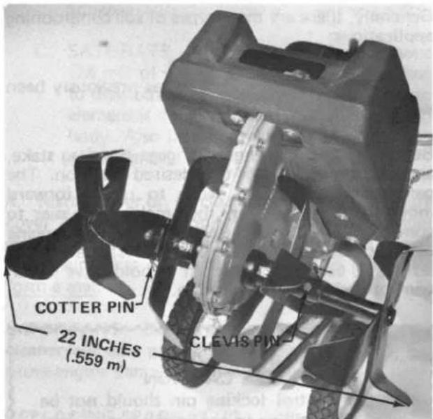
Figure 17 Maximum Width

Figure 18 Minimum Width
OPERATING INSTRUCTIONS
USING THE TILLER
The tiller is a multiple-use, soil conditioning product. It can be used to renovate a garden, flowerbed or lawn. Soil "conditioning" occurs when the soil is blended, mixed, aerated or pulverized by the rotation of the tines. Two or more passes may be required to condition soil properly; however, different types of soil will affect the total working time. Wet soil tends to ball up, stick to the tines, and may result in poor conditioning. Wet, tilled soil may dry into rock-like lumps with a hard crusty cover. This condition is not conducive to seed germination and plant growth. Wet soil may plaster onto the tine rotor, resulting in reduced penetration when tilling. In addition, any abnormal buildup of soil on the belts may cause mechanical damage. Therefore, use the tiller only when the ground is "dry" (when soil may be crumbled with the hand), and wash tiller after use to remove any accumulated dirt and vegetation.
Generally, there are three types of soil conditioning applications:
- Breaking up untilled soil.
- Conditioning soil that has previously been tilled.
- Cultivating.
Before starting the engine, engage the drag stake, and adjust wheels to the desired position. The penetrating drag stake tends to retard forward movement of the tiller, thus making it easier to control. When breaking up untilled soil run engine at maximum speed. To prevent fatigue of the left hand, use the locking pin to hold drive clutch control in the engaged position.

CAUTION
Clutch control locking pin should not be used when tilling in confined areas or near fences.
Initially, untilled soil and grass are broken apart by pressing down on the handles to produce slow forward movement and maximum rotation of the tines; and it may even be necessary to hold back on the handles to further reduce forward movement. After the soil is broken apart, slight upward pressure on the handles produces faster forward movement of the tiller. During the actual tilling operation you may try to maneuver a turn. The compact tiller is versatile and will react to turning maneuvers without any damage to the tiller. However, experience and soil conditions will dictate degree of turn. The tiller can be pulled backward and turned easily, since the drag stake pivots out of the ground.
To condition the soil effectively, a definite tilling pattern must be used. Till a single row; then skip a space equal to the width of the tines, and make the return pass. Continue this pattern until the entire area is broken apart. Next, condition the entire area again by tilling at right angles to the previously tilled swaths. When the entire area is broken up, till deeper by raising wheels and adjusting handle force for a slow propelling rate. A four-inch depth of conditioned soil is deep enough for most row crops and turf, seed-bed areas. Vine crops, however, usually require six or more inches of conditioned soil.
Another tiller application is conditioning soil that has been tilled previously. Even though the soil has been conditioned before, the ground must be dry for the effective reconditioning that may be required. Do not till when the soil is wet. Engine speed should be regulated to produce good pulverization of the soil, and this is affected by the type of soil being conditioned. Never condition the soil until it becomes granular or powdery, because the surface soil will have a tendency to pack and resist plant growth. If the general texture of the soil is somewhat sandy, use only enough engine speed to loosen the soil for planting. Other than engine speed, the use of the tiller and tilling pattern is the same as when untilled is first conditioned. Keep the wheels adjusted so that an erect, non-straining operating position can be maintained.
When cultivating - uprooting weeds - the tiller must be controlled carefully to avoid plant damage. To maintain control of the tiller, adjust wheels, engage drag stake, and reduce engine speed. Wheels should be adjusted to allow the operator to maintain an erect position.
In summary, till or cultivate the soil when it is dry, because better "conditioning" will result. Maximum engine speed is required to break up soil that has never been tilled. By comparison, regulate engine speed as required when conditioning soil that has already been tilled. Cultivating, by contrast, requires reduced engine speed so that precise control of the tiller can be maintained. And, after the tiller has been used, hose off any dirt and vegetation from the tines, pulleys, belts and shroud. Wipe engine with a damp cloth, in preference to spraying it with water. Store the tiller in a clean, dry garage or storage shed.
IMPORTANT: 1) Always make sure that air cleaner is cleaned and serviced before operating tiller. 2) Make sure blower and air cleaner are free of debris. Clean every 4 hours when tilling dry vegetation or dry, dusty soil. If this is not done, chaff will build up in blower housing, causing engine to overheat.
MAINTENANCE

CAUTION
Shut engine off before performing any maintenance service. To prevent possibility of accidental starting, pull high tension wire off spark plug. Make sure that wire does not contact plug accidentally (Fig. 19).

Figure 19
High Tension Wire
in V Notch
SERVICING AIR CLEANER
Tools Required: Screwdriver
NOTE: The air cleaner element must be cleaned after every 25 hours of engine operation. However, element must be cleaned every few hours when operating conditions are extremely dusty or sandy.
- Pull high tension wire off spark plug.
- Remove screw and cover to expose air cleaner element (Fig. 20).
- Inspect air cleaner element at the inlet holes on the bottom of air cleaner, and at the top of the air cleaner element. If element is dirty or discolored, it must be removed from the air cleaner body, then cleaned.
A. WASH element in a solution of liquid detergent and water. Squeeze element to remove dirt, but do not twist the element, because it may tear.
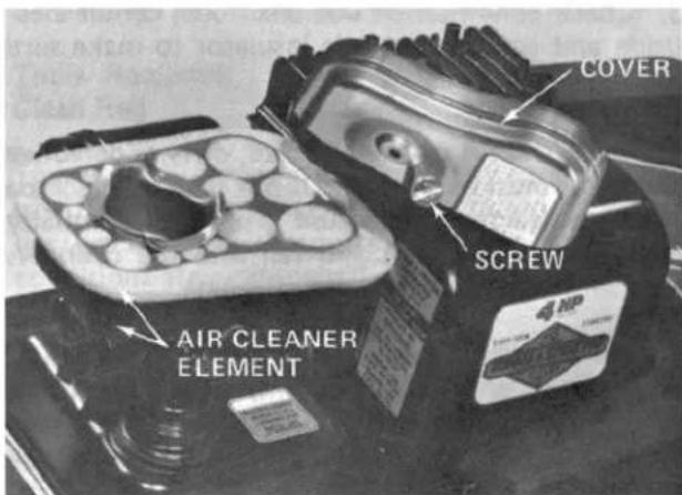
Figure 20
Air Cleaner Element
B. DRY element by wrapping it in a clean rag. Squeeze rag and element until element is dry.
C. SATURATE element with 5 teaspoons (25 ml) of engine oil, and squeeze element to distribute and remove excess oil. A damp element is desirable. Next, put element into body. Also install screen and spacer on top of element.
- Install cover on air cleaner body, and make sure cover and element form a seal. Mount air cleaner assembly on top of carburetor with long screw. Make sure that all parts are seated in place and form a seal.
IMPORTANT: Do not operate engine without air cleaner element and screw mounted in place, because engine damage will likely result.
REPLACING SPARK PLUG
Tools Required: Spark Plug Socket Wrench, Spark Plug Gapping Tool and Clean Rag
Since air gap between center and side electrodes of the spark plug increases gradually during normal operation of the engine, check condition of electrodes after every 25 operating hours. Recommended air gap is 0.030 of an inch (0.76 mm). Correct spark plugs to use are Champion RCJ-8 or Autolite AR7N.
- Clean area around spark plug so foreign matter cannot fall into cylinder when spark plug is removed.
- Pull high tension wire off spark plug and remove plug from cylinder head.
MAINTENANCE
- Check condition of side electrode, center electrode and center electrode insulator to make sure there is no damage.
IMPORTANT: A cracked, fouled, dirty or defective spark plug must be replaced. Do not sand blast, scrape or clean electrodes because grit may eventually release from the plug and fall into the cylinder. The result is usually a damaged engine.
- Set air gap between center and side electrodes at 0.030 of an inch (0.76 mm) (Fig. 21). Install correctly gapped spark plug with gasket seal, and tighten plug to 15 ft-lb (20.4 N'm). If torque wrench is not used, tighten plug firmly.

Figure 21 Air Gap Between Electrodes
- Do not install high tension wire onto spark plug unless tiller is to be used immediately. This prevents possibility of accidental starting.
CHANGING CRANKCASE OIL
Tools Required: 3/8 Inch Open End Wrench, Shallow Oil Drain Pan, and Clean Rag
Check oil level after every 5 hours of operation or each time tiller is used. Change oil after the first 2 hours of operation; thereafter, under normal conditions, change oil after every 25 hours of engine operation. However, change oil more frequently when engine is operated in dusty or sandy conditions. If possible, run engine just before changing oil; warm oil flows better and carries out more contaminants than does cool oil.
-
Position tiller on level surface so oil drains completely and a true reading results when crankcase is refilled.
-
Shut engine off, and pull high tension wire off spark plug.
-
Clean area around drain plug (Fig. 22). Next, place shallow drain pan below drain plug so oil can run into pan.
-
Remove drain plug from crankcase, and let oil drain into pan. To make sure that oil drains completely, tip tiller slightly to the rear.

Figure 22 Location of Oil Drain Plug Installed
- After oil drains completely, reinstall drain plug, and wipe up any oil that may have spilled.
- With tiller parked on level surface, fill crankcase with oil: Refer to Fill Crankcase With Oil, page 7.
CHECKING OIL LEVEL IN CHAIN CASE
Tools Required: Screwdriver and Clean Rag
Under normal operating conditions, the chain drive case needs to be checked only once a year to make sure oil level is maintained. However, if there is evidence of oil leaking from the chain case or bearings, check oil level more frequently. If oil leaks persist, contact your nearest Authorized TORO Service Dealer.
- Position tiller on a level surface.
- Clean area around oil level plug to prevent foreign matter from entering inspection hole when plug is removed.
MAINTENANCE
- Remove oil level plug (Fig. 23).
- A small amount of oil should flow from the inspection hole, indicating chain drive case is properly filled.
- Replace oil level plug.

Figure 23
Oil Level
Plug Removed
FILLING CHAIN DRIVE CASE
Tools Required: Screwdriver, Funnel, SAE 30 Oil, and Clean Rag
- Position tiller on a level surface.
- Clean area around oil level plug to prevent foreign matter from entering inspection hole when plug is removed.
- Remove oil level plug (Fig. 23).
- Tip tiller on the left side, insert funnel into oil inspection hole, and add a small amount of SAE 30 oil.
- Remove funnel; place tiller back upright. When a small amount of oil flows from the inspection hole, chain drive case is properly filled.
- Replace oil level plug.
LUBRICATING WHEELS AND IDLER PULLEY
Tools Required: Screwdriver, SAE 30 Oil, and Clean Rag
The wheel bushings and idler pulley must be lubricated after every 15 hours of operation or, if used less, once a year. Lubricate more frequently when conditions are extremely dusty or sandy.
- Clean area around wheel bushings with rag. Lubricate wheel bushing with a few drops of oil (Fig. 24). Spin wheels to distribute the oil, and wipe up any excess oil.

Figure 24
Lubricating Wheels
- Remove 6 screws holding the shroud to the tiller chassis; remove shroud (Fig. 25).

natural_image
Close-up of a hand using a tool to adjust or install a mechanical component, no visible text or symbols.Figure 25
Removal of Screws
Holding Shroud
MAINTENANCE
- Clean area around idler pulley and on back of idler pulley. Lubricate idler pulley hub and pivot with a few drops of SAE 30 oil (Fig. 26). Spin idler pulley to distribute oil; wipe up any excess oil.
- Replace shroud and fasteners.
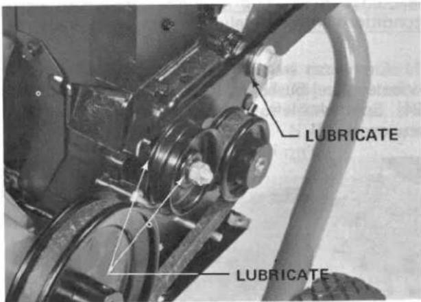
Figure 26 Lubrication Points
DRAINING GASOLINE FROM FUEL TANK
Tools Required: Pump-Type Siphon and Clean Rag

CAUTION
Since gasoline is highly flammable, to prevent potential fire hazard make sure engine is cool and drain gasoline outdoors. Wipe up any gas that may spill. Do not drain gasoline near open flames, because gasoline fumes may be ignited by a spark. Do not smoke when handling gasoline.
- Clean area around fuel tank to prevent foreign matter from entering filler hole when cap is removed.
- Using a pump-type siphon, pump gasoline into a clean gas can. This is the only method recommended for draining gasoline.
CLEANING ENGINE BLOWER HOUSING
Tools Required: 7/16 Inch Open End Wrench, Screwdriver and Brush
IMPORTANT: When tilling dry vegetation or under very dry, dusty conditions, clean blower housing every 2 to 4 hours of operation. Proceed as follows:
- Remove 6 screws that hold shroud to tiller chassis (Fig. 27).

natural_image
Close-up of a hand using a tool to adjust or install a mechanical component, no visible text or symbolsFigure 27 Removal of Screws Holding Shroud
- Remove the three 7/16 inch screws that hold engine blower housing to engine (Fig. 28).
- Clean all debris out of engine cooling fins.
- Reinstall engine blower housing and shroud.
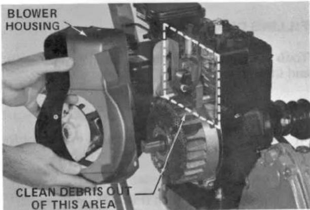
Figure 28 Blower Housing Removed
ADJUSTING BELT TENSION
If tines slip or do not rotate when tilling, it may be necessary to adjust belt tension.
- Remove spring from idler pulley arm.
MAINTENANCE
- Move spring up on link on the chain. Reinstall spring on idler pulley arm (Fig. 29).
- Start engine and engage clutch control drive: Tines should now rotate. Continue the above steps until tine rotation is evident, or slippage has been cured. Tines must not rotate when drive clutch control handle is released.

Figure 29 Adjusting Belt Tension
REPLACING DRIVE BELT
Tools Required: 3/8 Inch Open End Wrench, Screwdriver, and New Belt
Under normal conditions, belt replacement should not be necessary. However, if belt replacement is necessary, proceed as follows:
- Remove 6 screws holding shroud to tiller chassis (Fig. 30).

natural_image
Close-up of hands using a tool to adjust or install a mechanical component (no visible text or symbols)Figure 30 Removal of Screws Holding Shroud
- Remove belt from pulleys.
- Loosen belt guide locking screw (Fig. 31).
- Assemble new belt, and adjust the belt guide to allow 1/16 inch (1.6 mm) clearance between the bottom of the belt and the belt guide when clutch control is engaged (Fig. 31).
- Tighten belt guide locking screw.
- Start engine: With drive clutch control released, belt and chain case pulley must not rotate.
- Stop engine, and disconnect spark plug wire.
- Reassemble tiller shroud and screws.

Figure 31 Belt Replacement and Adjustment
CARBURETOR ADJUSTMENT
Carburetors are adjusted at the factory, and normally do not need adjustment unless they have been disassembled.
INITIAL ADJUSTMENT
Close needle valve (turn clockwise — (Fig. 32), then open 1 12 turns (turn counterclockwise). This initial adjustment will permit the engine to be started and warmed up before making final adjustment.
FINAL ADJUSTMENT
With drive clutch control released (tines stopped) and engine running at normal operating speed (approximately 3000 rpm without load) close the needle valve slowly (turn clockwise) until engine starts to lose speed (lean mixture). Then slowly open needle valve (turn counterclockwise), past the point of smoothest operation, until engine just
MAINTENANCE
begins to run unevenly. This mixture should be rich enough for best performance under load (Fig. 32).
Hold throttle in idling position. Turn idle adjusting screw until fast idle is obtained (1750 rpm).
Test the engine under full load. If engine tends to stall or die out, it usually indicates that the mixture is slightly lean, and it may be necessary to open the needle valve slightly (1/8 to 1/4 turn counterclockwise) to provide a richer mixture. This richer mixture may cause a slight unevenness in idling.
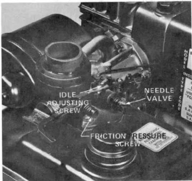
Figure 32 Carburetor With Air Cleaner Removed

WARNING
Engine must be running so final adjustment of carburetor can be performed. To guard against possible personal injury, disengage drive clutch control. Keep hands, feet, face, and other parts of the body away from the tines, belts and pulleys.
IMPORTANT: Air cleaner must be installed on the engine whenever carburetor is being adjusted. The air cleaner mounting screws must also be tight when engine is run. Fuel tank must be half full of gasoline to get best carburetor adjustment.
PREPARING TILLER FOR STORAGE
- Drain gasoline from fuel tank: Refer to Draining Gasoline From Fuel Tank, page 16. Next, start engine and let it run at idle speed until it stops because all gasoline is used.
- Pull high tension wire off spark plug, and clean area around the plug so foreign matter cannot fall into cylinder when plug is removed. Next, remove plug from cylinder head and pour two tablespoons (25 ml) of engine oil into spark plug hole. Pull recoil starter handle slowly to distribute oil on inside of cylinder. Then reinstall spark plug, and tighten it to 15 ft-lb (20.4 N·m). If torque wrench is not used, tighten plug firmly. DO NOT INSTALL HIGH TENSION WIRE ON SPARK PLUG.
- Drain oil from crankcase: Refer to Changing Crankcase Oil, page 14. However, do not fill crankcase with oil at this time.
- Clean dirt and chaff from outside of cylinder, cylinder head fins and blower housing. Also, remove vegetation, dirt and grime from external parts of tiller chassis, engine, shrouding and tines. Make sure idler pulley pivots freely.
- Check and tighten all cap screws, bolts, screws, nuts and mating parts. If any part is damaged, repair or replace it.
- Lubricate wheels and pivot points: Refer to Lubricating Wheels and Idler Pulley, page 15.
- "Touch up" all rusted or chipped paint surfaces. Make sure to sand affected area before painting.
- Fill crankcase with oil: Refer to Fill Crankcase With Oil, page 7. Clean air cleaner element: Refer to Servicing Air Cleaner, page 13.
TROUBLE SHOOTING
| Problem | Possible Causes | Corrective Action |
| Engine does not start. | 1. Gas tank is empty.2. Choke arm not in FULL position.3. Spark plug loose.4. High tension wire loose or disconnected from spark plug.5. Spark plug gap is incorrect.6. Spark plug is defective.7. Faulty points or condenser. | 1. Fill fuel tank with gasoline: Refer to Fill Fuel Tank With Gasoline, page 7.2. Move choke to FULL CHOKE position: Refer to Starting and Stopping Instructions, page 9.3. Tighten spark plug to 15 ft-lb (20.4 N·m).4. Install high tension wire on spark plug.5. Set gap between electrodes at 0.030 of an inch (0.76 mm).6. Install new, correctly gapped plug: Refer to Replacing Spark Plug, page 13.7. Contact Authorized TORO Service Dealer. |
| Engine starts hard or loses power. | 1. Dirt, water, or stale fuel in gas tank.2. Vent hole in fuel tank cap is plugged.3. Air cleaner is dirty. | 1. Drain gas and clean fuel tank. Fill tank with clean, fresh gasoline: Refer to Fill Fuel Tank With Gasoline, page 7.2. Clean or replace fuel tank cap.3. Clean the air cleaner element: Refer to Servicing Air Cleaner, page 13. |
| Engine operates erratically. | 1. Spark plug is defective.2. Spark plug gapped incorrectly.3. Air cleaner is dirty. | 1. Install new, correctly gapped plug: Refer to Replacing Spark Plug, page 13.2. Set gap between electrodes at 0.030 of an inch (0.76 mm).3. Clean the air cleaner element: Refer to Servicing Air Cleaner, page 13. |
TROUBLE SHOOTING
| Problem | Possible Causes | Corrective Action |
| Engine idles poorly. | 1. Air cleaner is dirty.2. Oil level in crankcase is low.3. Air slots in engine shroud are plugged.4. Cooling fins and air passages under engine blower housing are plugged.5. Improper idle adjustment. | 1. Clean the air cleaner element: Refer to Servicing Air Cleaner, page 13.2. Add oil to crankcase: Refer to Fill Crankcase With Oil, page 7.3. Remove obstruction from slots.4. Remove obstruction from cooling fins and blower housing: Refer to Cleaning Engine Blower Housing, page 16.5. Adjust carburetor properly, page 17. |
| Engine misfires at high speed. | 1. Air gap between electrodes of spark plug is too close.2. Carburetor adjusted incorrectly. | 1. Set air gap at 0.030 of an inch (0.76 mm).2. Adjust carburetor: Refer to Carburetor Adjustment, page 17. |
| Engine overheats. | 1. Cooling air flow is restricted.2. Oil level in crankcase is low.3. Incorrect spark plug. | 1. Remove any obstruction from slots in shroud, blower housing, air passages and cooling fins on engine (Fig. 30).2. Add oil to crankcase: Refer to Fill Crankcase With Oil, page 7.3. Install Champion RCJ8 spark plug that is gapped at 0.030 of an inch. |
| Tiller vibrates abnormally. | 1. Tine section is loose.2. Engine mounting bolts are loose.3. Improper carburetor adjustment.4. Air cleaner plugged. | 1. Secure tine section with clevis pin and hair pin cotter.2. Tighten engine mounting bolts.3. Adjust carburetor properly, page 17.4. Service air cleaner, page 13. |
| Tines do not rotate. | 1. Belt is broken.2. Belt is adjusted incorrectly. | 1. Contact Authorized TORO Service Dealer.2. Adjust drive clutch belt: Refer to adjusting Belt Tension, page 16. |
IDENTIFICATION AND ORDERING
MODEL AND SERIAL NUMBERS
The tiller has two identification numbers: a model number and a serial number. The two numbers are stamped on a decal which is located on the rear of the chain drive case (Fig. 33). In any correspondence concerning the tiller, supply the model and serial numbers to make sure that correct information and replacement parts are obtained.
To order replacement parts from an Authorized TORO Service Dealer, supply the following information:
- Model and serial numbers of the tiller.
- Part number, description, and quantity of part(s) desired.
NOTE: Do not order by reference number if a parts catalog is being used; use the PART NUMBER.

Figure 33 Location of Model and Serial No. Decal
MAINTENANCE RECORD
| Date | Hours Used | Oil Change | Air Cleaner Service | Lubrication | Inspect Drive Belt | Winter Storage | Spring Service | Spark Plug | |
MAINTENANCE RECORD
| Date | Hours Used | Oil Change | Air Cleaner Service | Lubrication | Inspect Drive Belt | Winter Storage | Spring Service | Spark Plug | |
The Toru Promise
A ONE YEAR LIMITED WARRANTY
The Toro Company promises to repair your TORO Product if defective in materials or workmanship. The following time periods from the date of purchase apply:
Residential Product 1 Year
Residential Products Used Commercially . . . 45 Days
The costs of parts and labor are included, but the customer pays the transportation costs. Just return any residential product to an Authorized TORO Service Dealer or TORO distributor.
Should you feel your TORO Product is defective and wish to rely on The Toro Promise, the following procedure is recommended:
- Contact any Authorized TORO Service Dealer, TORO Master Service Dealer, or TORO Distributor (the Yellow Pages of your telephone directory is a good reference source).
- He will either instruct you to return the product to him or recommend another Authorized TORO Service outlet which might be more convenient.
- Bring the product along with your original sales slip, or other evidence of purchase date, to the service dealer.
- The servicing dealer will inspect the unit, advise you whether the product is defective and, if so, make all repairs necessary to correct the defect without extra charge to you.
If for any reason you are dissatisfied with the dealer's analysis of the defect or the service performed, you may contact us.
Write:
TORO Consumer Service Department
8111 Lyndale Avenue South
Minneapolis, Minnesota 55420
The above remedy of product defects through repair by an Authorized TORO Service Dealer is the purchaser's sole remedy for any defect.
THERE IS NO OTHER EXPRESS WARRANTY. ALL IMPLIED WARRANTIES OF MERCHANTABILITY AND FITNESS FOR USE ARE LIMITED TO THE DURATION OF THE EXPRESS WARRANTY.
Some states do not allow limitations on how long an implied warranty lasts, so the above limitation may not apply to you.
This warranty applies only to parts or components which are defective and does not cover repairs necessary due to normal wear, misuse, accidents, or lack of proper maintenance. Regular, routine maintenance of the unit to keep it in proper operating condition is the responsibility of the owner.
All warranty repairs reimbursable under The Toro Promise must be performed by an Authorized TORO Service Dealer using Toro approved replacement parts.
Repairs or attempted repairs by anyone other than an Authorized TORO Service Account are not reimbursable under The Toro Promise. In addition, these unauthorized repair attempts may result in additional malfunctions, the correction of which is not covered by warranty.
THE TORO COMPANY IS NOT LIABLE FOR INDIRECT, INCIDENTAL OR CONSEQUENTIAL DAMAGES IN CONNECTION WITH THE USE OF THE PRODUCT INCLUDING ANY COST OR EXPENSE OF PROVIDING SUBSTITUTE EQUIPMENT OR SERVICE DURING PERIODS OF MALFUNCTION OR NON-USE.
Some states do not allow the exclusion or limitation of incidental or consequential damages, so the above limitation or exclusion may not apply to you.
This warranty gives you specific legal rights, and you may also have other rights which vary from state to state.
COUNTRIES OTHER THAN THE UNITED STATES OR CANADA
Customers who have purchased TORO products exported from the United States or Canada should contact their TORO Distributor (Dealer) to obtain guarantee policies for your country, province or state. If for any reason you are dissatisfied with your Distributor's service or have difficulty obtaining guarantee information, contact
the TORO importer. If all other remedies fail, you may contact us at The Toro Company.
International Group
Service Department
One Corporate Center
7401 Metro Boulevard
Minneapolis, Minnesota 55435 U.S.A.
- FOREWORD
- OPTIONAL SPARK ARRESTER
- 392190 Spark Arrester Assembly
- SAFETY INSTRUCTIONS
- BEFORE OPERATING
- WHILE OPERATING
- MAINTAINING TILLER
- SPECIFICATIONS
- LOOSE PARTS
- SETTING UP INSTRUCTIONS
- To rotate handles:
- KNOW YOUR TILLER
- PREPARATION BEFORE STARTING
- FILL CRANKCASE WITH OIL
- FILL FUEL TANK WITH GASOLINE
- DANGER
- CHAIN DRIVE CASE
- CONTROLS
- STARTING AND STOPPING INSTRUCTIONS
- CAUTION
- OPERATING INSTRUCTIONS
- BREAK-IN
- DRAG STAKE
- ADJUSTING WHEELS
- CHANGING WIDTH OF SWATH
- USING THE TILLER
- MAINTENANCE
- SERVICING AIR CLEANER
- Tools Required: Screwdriver
- REPLACING SPARK PLUG
- CHANGING CRANKCASE OIL
- CHECKING OIL LEVEL IN CHAIN CASE
- FILLING CHAIN DRIVE CASE
- LUBRICATING WHEELS AND IDLER PULLEY
- DRAINING GASOLINE FROM FUEL TANK
- CLEANING ENGINE BLOWER HOUSING
- ADJUSTING BELT TENSION
- REPLACING DRIVE BELT
- CARBURETOR ADJUSTMENT
- INITIAL ADJUSTMENT
- FINAL ADJUSTMENT
- WARNING
- PREPARING TILLER FOR STORAGE
- IDENTIFICATION AND ORDERING
- MODEL AND SERIAL NUMBERS
- The Toru Promise
- COUNTRIES OTHER THAN THE UNITED STATES OR CANADA
Brand : TORO
Model : 58336
Category : Milling machine