SIMRAD Fuel Flow Sensor - Fuel Flow Sensor

Fuel Flow Sensor - Fuel Flow Sensor SIMRAD - Free user manual and instructions

Find the device manual for free Fuel Flow Sensor SIMRAD in PDF.

📄 2 pages English EN Download 💬 AI Question 10 questions ⚙️ Specs
Notice SIMRAD Fuel Flow Sensor - page 1
Pick your language and provide your email: we'll send you a specifically translated version.
Product Type Fuel Flow Sensor
Brand Simrad
Compatible Fuel Gasoline only
Flow Rate Range 0.6 - 15 US Gal/hour (2.37 - 170.1 L/hour)
Back Pressure 0.5 psi at 20 US Gal/hour
Fuel Line Size 3/8 inch (9.5 mm)
Drop Cable Length 3 m (10 ft)
Connector Type Micro-C (NMEA 2000)
Installation Orientation Vertical, arrow pointing upwards
Mounting Position Above maximum fuel tank level
In-line Filter Required Yes, between tank and sensor
Network Compatibility NMEA 2000 via Micro-C
Power Supply 12 V DC via network
Operating Environment For gasoline engines only
Not For Diesel engines or fuel systems with return lines
Included Accessories Sensor, Micro-C T-joint, stainless steel hose clamps
Required Tools Sharp knife, screwdriver
Safety Warning Flammable - keep away from sparks and open flames
Maintenance Regularly inspect fuel system; carry spare filter and splice barb

Frequently Asked Questions - Fuel Flow Sensor SIMRAD

What type of fuel can be used with the Simrad Fuel Flow Sensor?
The Simrad Fuel Flow Sensor is designed for gasoline only. It does not work with diesel or any fuel system with a return line.
Can the sensor be used with diesel engines?
No, the sensor is specifically for gasoline engines. It will not operate properly on diesel fuel systems.
What flow rates does the sensor measure?
The sensor measures flow rates from 0.6 to 15 US Gal/hour (2.37 to 170.1 L/hour).
What size fuel line is required?
The sensor is designed for a 3/8 inch (9.5 mm) fuel hose. If your engine uses different hoses, install a section of 3/8 inch line.
How should the sensor be mounted?
Mount the sensor vertically with the flow direction arrow pointing upwards. It must be installed above the fuel tank's maximum fuel level to prevent leakage.
Is a fuel filter necessary?
Yes, you must install an inline fuel filter between the tank and the sensor to prevent debris from clogging the turbine.
What tools are needed for installation?
You will need a sharp knife to cut the fuel line and a screwdriver to tighten the hose clamps.
How long is the drop cable?
The drop cable is 3 meters (10 feet) long and ends with a male Micro-C connector for NMEA 2000 networks.
Can the sensor be used with fuel return line systems?
No, the sensor is not compatible with fuel systems that have a return line or stump.
How do I connect the sensor to the network?
Connect the sensor's drop cable to a powered Micro-C NMEA 2000 compliant network using the provided T-joint. The network requires a 12V DC power supply and terminators.

User questions about Fuel Flow Sensor SIMRAD

0 question about this device. Answer the ones you know or ask your own.

Ask a new question about this device

The email remains private: it is only used to notify you if someone responds to your question.

No questions yet. Be the first to ask one.

Download the instructions for your Fuel Flow Sensor in PDF format for free! Find your manual Fuel Flow Sensor - SIMRAD and take your electronic device back in hand. On this page are published all the documents necessary for the use of your device. Fuel Flow Sensor by SIMRAD.

USER MANUAL Fuel Flow Sensor SIMRAD

Whats in the box Fuel Flow Sensor Micro-C T-Joiner Stainless steel hose clamps

Tools required Overview Sharp knife for cutting fuel line Screw driver for tightening hose clamp Other parts required The Fuel Flow was designed to fit a typical 3/8" SAE USCG Type A1 fuel hose. If your engine has different diameter hoses or metal fuel lines, a section of 3/8" fuel line must be installed between the sensor and the existing lines. Cable ties for securing Fuel Flow Sensor

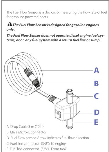
The Fuel Flow Sensor is a device for measuring the flow rate of fuel for gasoline powered boats. ▲ The Fuel Flow Sensor is designed for gasoline engines only. The Fuel Flow Sensor does not operate diesel engine fuel sys- tems, or on any fuel system with a return fuel line or sump. A Drop Cable 3 m (10 ft) B Male Micro-C connector C Fuel Flow sensor: Arrow indicates fuel flow direction D Fuel line connector (3/8): To engine E Fuel line connector (3/8): From tank

Before commencing the installation Caution: Gasoline is extremely flammable. If possible, drain the fuel line before you start or shut any flow valves located at the tank. Keep sparks and flame away from the work area. After installation, remember to clean up any spilled fuel. DANGER No Smoking No Open Flames No Sparks GASOLINE 3 Fuel Filter You must install an in-line fuel filter between the tank and the Fuel Sensor sensor. This will prevent a malfunction caused by contaminated fuel. Debris in unfiltered fuel can clog the sensor's turbine and result in rough performance or engine shut down. As with any fuel system, we recommend you always carry onboard a spare fuel filter and an in-line (3/8") splice barb. This allows you to remove a clogged Fuel Sensor or fuel filter and restore engine operation if the fuel filter fails. We strongly recommend that you inspect your entire fuel system at regular intervals.

Plan the installation Use one Fuel Flow Sensor for each engine A Fuel Flow sensor: Arrow indicates fuel flow direction B Fuel Filters: One before each fuel sensor C Fuel Tank

Plan the installation Mount to vibration free surface with the flow direction arrow pointing upwards. Mount as close as possible to the fuel tank To engine Fuel flow direction From tank Mount vertically

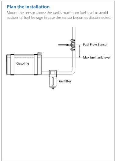
Plan the installation Mount the sensor above the tank's maximum fuel level to avoid accidental fuel leakage in case the sensor becomes disconnected. Fuel Flow Sensor Max fuel tank level Gasoline Fuel filter

Install the fuel flow sensor Cut the 3/8" fuel line at the appropriate place

Install the fuel flow sensor Slide hose clamps on to the fuel line

Install the fuel flow sensor Push the fuel hose on to the sensors barbs checking the flow direction is correct

Install the fuel flow sensor Tighten to hose clamps

Install the fuel flow sensor Secure the Fuel Flow Sensor taking care not to compress the fuel hose

Connect the Fuel Flow Sensor to the network Dimensions The Fuel Flow Sensor connects to a powered Micro-C NMEA 2000 compliant network using the provided T-Joiner A Micro-C drop cable 3 m (10 ft) B Fuel Flow Sensor C Micro-C network terminators (Note: a small network could have a terminator built in to the power cable connected at one end) D Micro-C CAN bus backbone (NMEA 2000, IEC61162-1/2) E 12 V DC Power supply. Connect via a switch and 5 amp fuse A B C D E C

Specifications Flow rates measured (optimum): 0.6 - 45 Gal US / Hour 2.27 - 170 Li/Hour Back pressure 0.5 psi / 20 Gal US / Hour PGNs transmitted 59392 - ISO Acknowledgment 59904 - ISO Request 60928 - ISO Address Claim 126996 - Product Information 127489 - Engine Parameters, Dynamic

Manual assistant
Powered by Anthropic
Waiting for your message
Product information

Brand : SIMRAD

Model : Fuel Flow Sensor

Category : Fuel Flow Sensor