
CP1-FRD1 - Car accessory PAC - Free user manual and instructions
Find the device manual for free CP1-FRD1 PAC in PDF.


| Product Type | Factory matched plug & play harness for CANPRO CP1-S CAN-Bus Interface Module |
| Compatible Vehicles | Select Ford models using 8pin data harness at Steering Column Control Module (SCCM) |
| Number of Outputs | 9 outputs (channels 1-9) |
| Output Current per Channel | 250 mA (low current; requires relay for higher loads) |
| Output Descriptions | Accessory, Illumination, Speed Pulse, Reverse, Ignition (or Ready-to-Drive for EVs), Left Turn Signal, Right Turn Signal, High Beam, Parking Brake |
| Output Polarity | Positive (250mA) for outputs 1-8, Negative (250mA) for output 9 (Parking Brake) |
| Wire Colors | White-Red, Blue, Green-Black, Violet-Black, Yellow-Black, Red-Black, Gray-Red, Blue-Black, Brown-Black |
| DIP Switches | 8 DIP switches for configuration (see installation diagram) |
| LED Status Indicator | Fast flashing RED (update mode), slow flashing GREEN (normal operation), slow GREEN + RED flashes (system fault with channel indication) |
| Main Functions | Provides access to vehicle CAN-Bus signals for aftermarket devices: radar detectors, camera activation, sound system upgrades, lighting, etc. |
| Installation Requirement | Vehicle must be off before disconnecting 8pin harness; steering column shroud must be removed |
| Safety Notes | Unused outputs must be insulated; low current outputs require relay for additional current |
| Fuse Protection | 3 amp fuse on yellow wire near 16pin connector |
| Technical Support | Email: support@PAC-audio.com, Phone: 727-592-5991, Chat: PAC-Audio.com |
| Included Components | CP1-FRD1 harness, CANPRO CP1-S module (sold separately?) - harness includes 16pin connector to module and 8pin vehicle connectors |
Frequently Asked Questions - CP1-FRD1 PAC
User questions about CP1-FRD1 PAC
0 question about this device. Answer the ones you know or ask your own.
Ask a new question about this device
Download the instructions for your Car accessory in PDF format for free! Find your manual CP1-FRD1 - PAC and take your electronic device back in hand. On this page are published all the documents necessary for the use of your device. CP1-FRD1 by PAC.
USER MANUAL CP1-FRD1 PAC
Introduction and Features
The CP1-FRD1 is a factory matched plug & play harness for use with the CANPRO CP1-S CAN-Bus Interface Module for select Ford Model applications using the 8pin data harness for connection at the Steering Column Control Module (SCCM). The harness and module allow a simple and safe way to access vehicle information, status and triggers from the CAN-Bus for a wide range of aftermarket uses such as radar detectors, camera activation, sound system upgrades, lighting and more!
Important Notes
- Any unused outputs should be insulated to prevent shorting.
- The outputs of the CANPRO are low current (250mA) and require the use of a separate relay if additional current is required.
- The vehicle should be in a resting state prior to opening connection to the 8pin data harness. See Installation note for further information.
Wiring Connection Chart
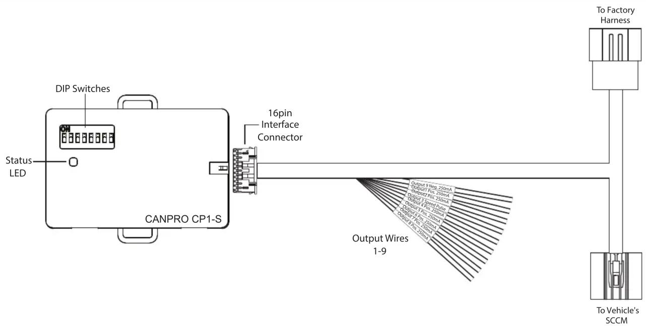
Outputs
| Description | Polarity | Wire Color | |
| Output 1 | Accessory | + Positive (250mA) | White-Red |
| Output 2 | Illumination | + Positive (250mA) | Blue |
| Output 3 | Speed Pulse | Pulse | Green-Black |
| Output 4 | Reverse | + Positive (250mA) | Violet-Black |
| Output 5 | Ignition* | + Positive (250mA) | Yellow-Black |
| Output 6 | Left Turn Signal | + Positive (250mA) | Red-Black |
| Output 7 | Right Turn Signal | + Positive (250mA) | Gray-Red |
| Output 8 | High Beam | + Positive (250mA) | Blue-Black |
| Output 9 | Parking Brake | - Negative (250mA) | Brown-Black |
* In Electric Vehicles, Output 5 provides a positive output when the vehicle is in a “Ready to Drive” state.
Installation
NOTE! Verify the vehicle is off prior to disconnecting the 8pin vehicle harness and do not turn on the accessory or ignition until the 8pin male and female connectors from the CP1-FRD1 are connected.
- Set the DIP switches on the CP1-S as shown in below.

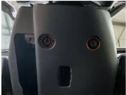
- To access the vehicle's CAN data harness, the steering column shroud must be removed. Remove the two screws (7mm or 9/32") from the underside of the shroud. (FIG A)*
- Pull downward along the bottom edge of the shroud to release the retaining clips and pull towards the rear of the vehicle to remove the bottom portion of the shroud. (FIG B)*
- Ensure the vehicle is Powered Off and unplug the 8pin CAN data harness pictured. (FIG C)*
- Connect one end of the CP1-FRD1 harness to the matching connector in the vehicle. Connect the remaining vehicle connector from the CP1-FRD1 to the other end of the vehicle harness and route the CP1-FRD1 harness along the OEM harness toward the bottom of the dash.(FIG D)*
- Determine a mounting location for the CANPro module in a place where it does not interfere with the movement of any vital vehicle equipment and secure the module.
- Connect the 16pin CP1-FRD1 connector into the CANPro and lengthen and route any Output wires needed. Insulate any unused Output wires!
- After wire connections and testing are complete, secure the CP1-S module and reinstall the console panels.
FIG A
natural_image
Close-up of a car's front panel showing two circular buttons with red dashed lines, no visible text or symbolsFIG B

natural_image
Close-up of a car's rear panel showing green directional arrows pointing to components (no text or symbols visible)FIG C

FIG D

natural_image
Close-up of a mechanical assembly with yellow and red dotted lines indicating components (no visible text or symbols)LED Status Information
| ACTION/COLOR | Description |
| Fast Flashing RED Update mode | for updating of the application or resource files. |
| Slow Flashing (0.5sec) GREEN Normal Operation | |
| Slow Flashing (0.5sec) GREEN, plus additional 0.5sec RED | System Fault. The number of times the interface flashes RED indicates the channel (output) with a fault condition. For example, if the LED flashes GREEN, then flashes RED twice, then back to Green, Channel 2 has a fault condition.To check the fault, see Troubleshooting section below. |
Troubleshooting
- No LED activity: Disconnect and reconnect the CP1, does the LED flash? If not, check the 3 amp fuse in the fuse-holder that is located 2 inches from the 16pin connector on the Yellow wire.
- No Outputs: Verify the DIP switch setting is correct (Installation section, FIG A). If the DIP switch setting needs to be changed, unplug the CP1, change the DIP setting and then reconnect. If the LED is flashing green, test the outputs using a multimeter. If the multimeter is showing the proper output, add a relay to the output to increase current capability.
- System Fault: Disconnect the faulty output (1-9), disconnect and reconnect the 16pin connector to the CP1 so that it loses and gains back power and ground, does it stop flashing red? Check wiring to faulty output to make sure it is not shorted to ground, or add a relay.
Technical Support
Email: support@PAC-audio.com
Phone: 727-592-5991
Chat: PAC-Audio.com

Brand : PAC
Model : CP1-FRD1
Category : Car accessory