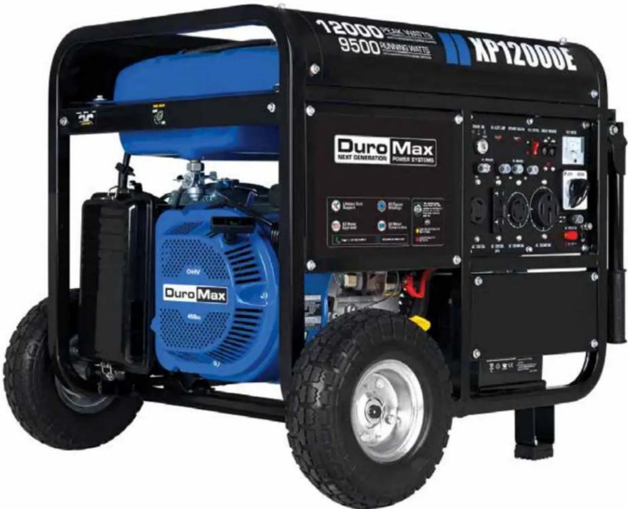
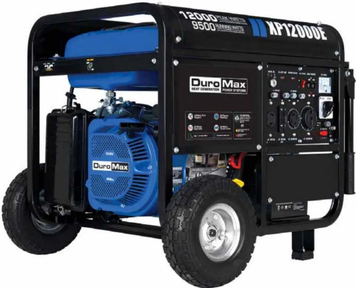
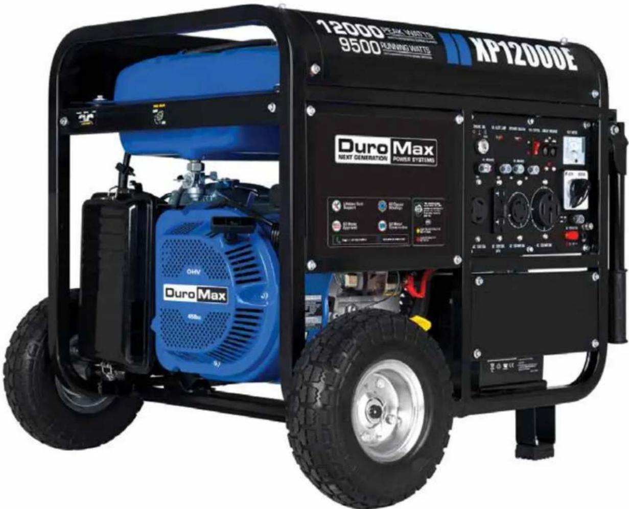
XP12000E - Generator DuroMax - Free user manual and instructions
Find the device manual for free XP12000E DuroMax in PDF.


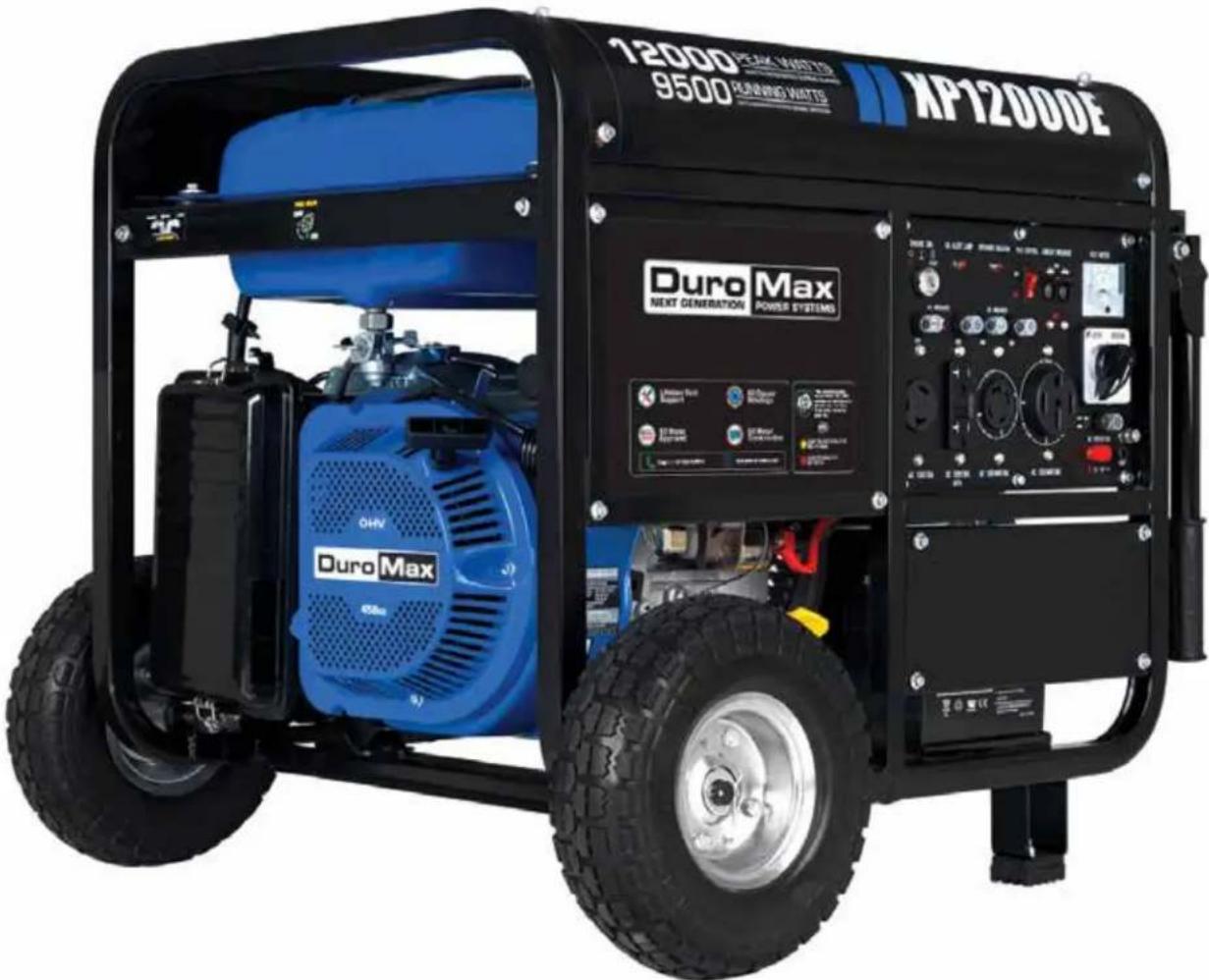
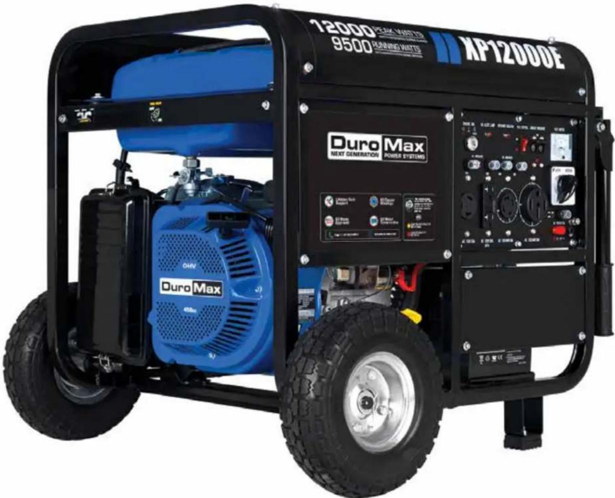
| Product Type | Portable Generator |
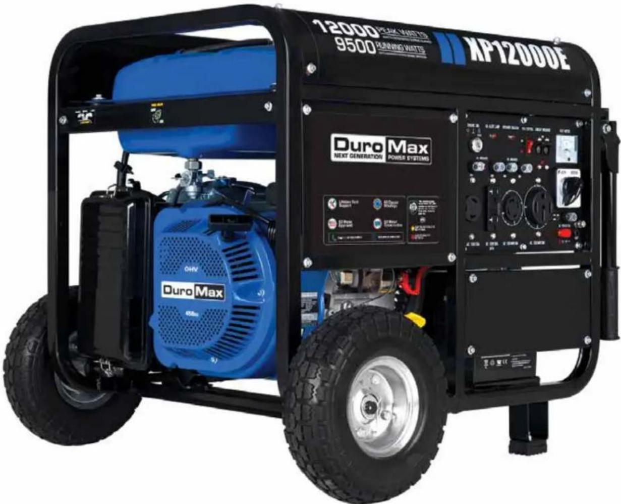
| Model | XP12000E |
| Brand | DuroMax |
| Peak Wattage (Gasoline) | 12,000 W |
| Rated Wattage (Gasoline) | 9,500 W |
| AC Voltage | 120/240 V |
| AC Frequency | 60 Hz |
| Phase | Single Phase |
| Engine Displacement | 457 cc |
| Engine Type | 4-Stroke, OHV |
| Starting Type | Electric & Recoil |
| Fuel Type | Gasoline |
| Gas Tank Capacity | 8.3 US gal (31 L) |
| Oil Capacity | 40.5 fl oz (1.2 L) |
| Recommended Oil | 10W-30 |
| Run Time at 50% Load | 8 hours |
| Noise Level | < 74 dB |
| Dimensions (L x W x H) | 30 in x 30 in x 26 in |
| Weight | 217 lbs |
| Outlets | 120V 3-Prong (5-20R), 120V 3-Prong Twist Lock (L5-30R), 240V 4-Prong Twist Lock (L14-30R), 50A Receptacle, 12V DC Charging Posts |
| Circuit Breaker | Yes, resettable |
| Voltage Selector Switch | Power Boost (120V Only / 120/240V) |
| Idle Control | Yes, for fuel savings |
| CO Alert System | Yes, automatic shutdown and indicator |
| Grounding | Required via ground terminal |
| Warranty | 3 years parts (residential), 1 year commercial |
Frequently Asked Questions - XP12000E DuroMax
User questions about XP12000E DuroMax
0 question about this device. Answer the ones you know or ask your own.
Ask a new question about this device
Download the instructions for your Generator in PDF format for free! Find your manual XP12000E - DuroMax and take your electronic device back in hand. On this page are published all the documents necessary for the use of your device. XP12000E by DuroMax.
USER MANUAL XP12000E DuroMax
This manual provides information regarding the operation and maintenance of these products. We have made every effort to ensure the accuracy of the information in this manual. We reserve the right to change this product at any time without prior notice.
5800 Ontario Mills Pkwy
Ontario, CA 91764 USA
www.duromaxpower.com
Call our Customer Care Team Toll Free 8-5 pm PST Mon-Fri
844-DUROMAX



natural_image
A solid blue square with no text, numbers, or symbols visible.



natural_image
Pure blue square with no text, numbers, or symbols


natural_image
Pure blue square with no text, numbers, or symbols


natural_image
Pure blue square with no text, numbers, or symbolsCONTENTS
1. Introduction
Introduction...... 6
General Safety Procedures.... 8
Carbon Monoxide Safety 14
Unit and Purchase Information.... 16
2. Generator Components
Generator Components 18
Package Contents 20
3. Generator Setup
Shipping Braces 23
Wheel Kit Installation.... 24
Connect the Battery 26
Adding Oil 27
Adding Gasoline 28
Grounding the Generator 29
High Altitude Operation 29
4. Starting the Generator
Check the Oil 32
Check the Gas Level 33
Starting the Generator 34
Starting the Generator Using Recoil Start 36
5. Using the Generator
AC Usage 40
Connecting the Generator to a Home 43
Connecting a Load to the Generator.... 44
Choosing the Right Power Cord 45
DC Usage 46
Voltage Selector Switch 48
Idle Control Usage 48
6.
Stopping the Generator
Shutting Down the Generator....51
7.
Maintenance and Care
Maintenance Schedule....54
Break-In Period 55
Maintenance Log....55
Checking the Oil 56
Changing the Oil....57
Cleaning the Air Filter 58
Spark Plug Maintenance 60
Emptying the Gas Tank 62
Cleaning the Fuel Filter Cup....64
Transporting the Generator 65
Storing the Generator for Use Within 30 Days....67
Storing the Generator for Longer Than 30 Days....68
Specifications....70
8.
Troubleshooting
Basic Troubleshooting....72
Changing/Inspecting the Carbon Brushes 73
Changing/Inspecting the AVR 75
Wiring Diagram 78
9.
Warranty....80
10.
Customer service....83
For more information and resources on this model scan the QR code below to link to our website product information page.

Duro Max
Duro Max
THE DUROMAX WAY
The DuroMax Way is more than just a brand, it is our understanding and appreciation of just how important power can be to someone without it...

natural_image
Family of four sitting on stone steps, smiling and engaged in conversation (no visible text or symbols)DUROMAX FOR HOME
Electricity in our home not only provides comfort but safety as well. From keeping the heat or A/C on to keeping our food cold, power is essential to our daily lives. Inevitability when disaster strikes and we are left without power for a prolonged period of time, our way of life is put at risk. This is by far the most critical time for reliable portable power.

natural_image
Two construction workers in yellow hard hats and blue shirts working on a metal structure (no visible text or symbols)DUROMAX FOR WORK
On the job site, portable power allows you the ability to get work done in remote locations when traditional power sources are usually unavailable. Equipment like table saws, sanders, and work lights are a necessity and portable power can play a critical role in getting a job done successfully and efficiently.

natural_image
Family of four gathered outdoors near a campfire, with a camouflaged vehicle in the background (no visible text or symbols)DUROMAX FOR PLAY
Camping outdoors in a remote location can get one in touch with nature and allow them to forget the stress of the day to day grind. Here portable power can provide comfort as well as safety. With portable power, you can keep your cell phone charged, light up your campsite, or even brew a cup of coffee, all while being miles from civilization.
The DuroMax Way is a commitment to excellence. This vision is focused on the quality, reliability, and durability of our products combined with outstanding customer service. We understand that having dependable power whenever and wherever you need it provides comfort, safety, and peace of mind. It is through this philosophy that DuroMax achieves our vision of...
POWERING EVERYONE... ANYWHERE!
INTRODUCTION
DuroMax Power Equipment is headquartered in Ontario, California and is the industry's leader in Dual Fuel portable generator technology. In addition to a full assortment of portable generators ranging from digital inverters to large 15,000-watt portable standby units, their product line includes pressure washers, engines, pumps, and accessories.
The foundation of our company is built on quality, reliability, durability, and customer service. At DuroMax our vision is simple, we are committed to Powering Everyone... Anywhere!

STOP
Please do not return to the store.
DuroMax representatives are ready to help you with any questions, concerns, or issues about your new product. We can guide you through assembly, start up, and how to operate your new generator. We want you to be able to put your new generator to use right away!
CALL US BEFORE YOU CONSIDER RETURNING THE PRODUCT!
TOLL-FREE 1-844-DUROMAX
Notice Regarding Emissions
Engines that are certified to comply with U.S. EPA emission regulations for SORE (Small off Road Equipment), are certified to operate on regular unleaded gasoline and may include the following emission control systems: (EM) Engine Modifications and (TWC) Three-Way Catalyst (if so equipped).
GENERAL SAFETY PROCEDURES

SAFETY ALERT SYMBOL
The safety alert symbol is used with one of the safety words (DANGER, WARNING, or CAUTION) to alert you of hazards. Please pay attention to these hazard notices both in this manual and on the engine.
Please familiarize yourself with the following safety symbols and words:
- DANGER: Indicates a hazard that will result in serious injury or death if instructions are not followed.
- WARNING: Indicates a strong possibility of causing serious injury or death if instructions are not followed.
- CAUTION: Indicates a possibility of personal injury or equipment damage if instructions are not followed.

DANGER: This generator produces poisonous carbon monoxide gas when running. This gas is both odorless and colorless. Even if you do not see or smell gas, carbon monoxide may still be present. Breathing this poison can lead to headaches, dizziness, drowsiness, and eventually death.
• Use outdoors ONLY in non-confined areas.
- Keep several feet of clearance on all sides to allow proper ventilation of the generator.

WARNING: The exhaust from this product contains chemicals known to the State of California to cause cancer, birth defects, or other reproductive harm.

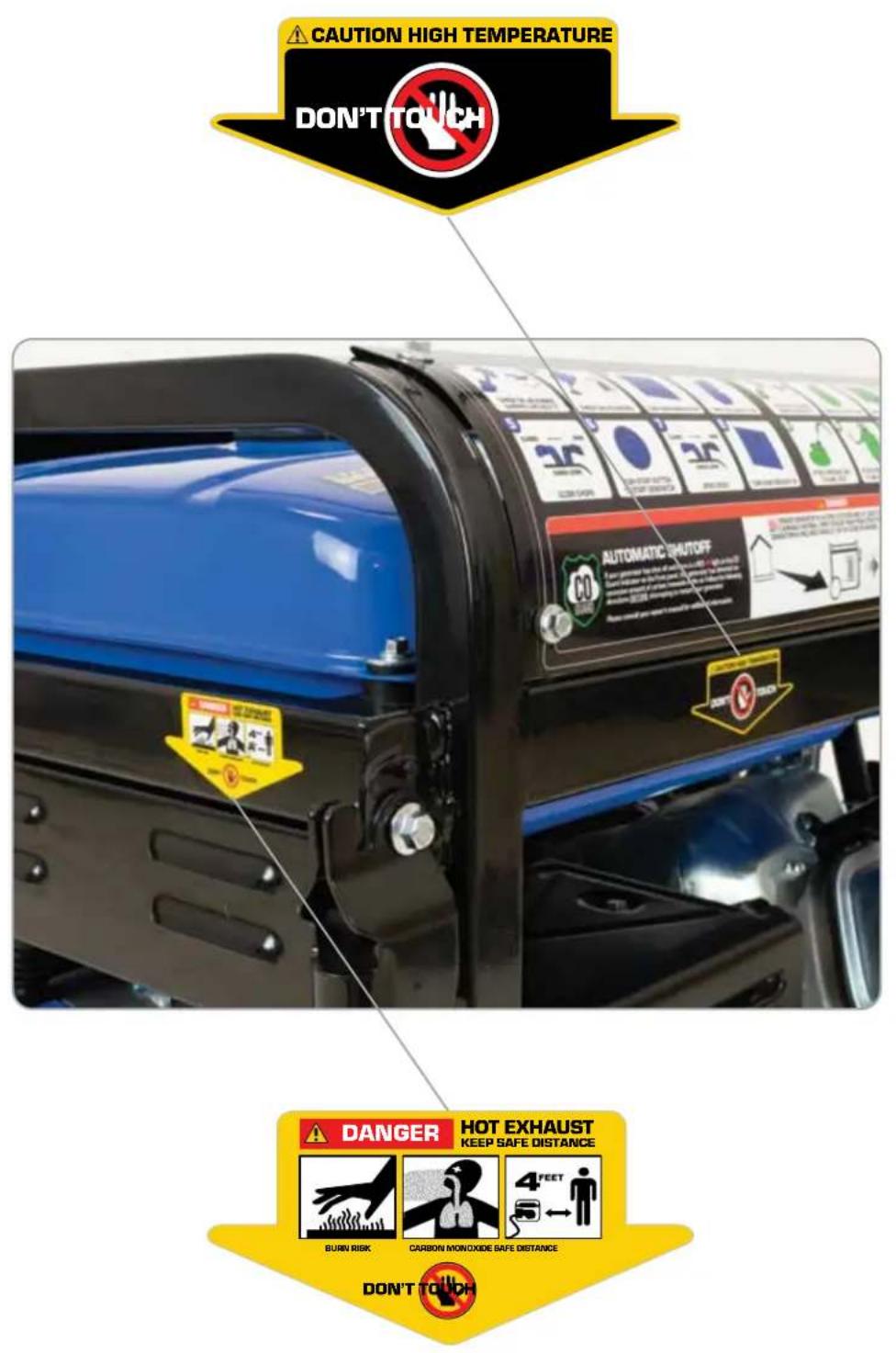
WARNING: This generator produces heat when running. Temperatures near exhaust can exceed 150^ F ( 65^ C).
- Do not touch hot surfaces. Pay attention to warning labels on the generator denoting hot parts of the machine.
- Allow generator to cool several minutes after use before touching engine or areas which heat during use.

WARNING: This generator may emit highly flammable and explosive gasoline vapors, which can cause severe burns or even death. A nearby open flame can lead to an explosion even if not directly in contact with gasoline.
- Do not operate near an open flame.
- Do not smoke near the generator.
• Always operate on a firm, level surface.
• Always turn the generator off before refueling. - Allow generator to cool for at least 2 minutes before removing the fuel cap. Loosen cap slowly to relieve pressure in the tank.
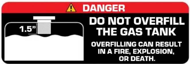
- Do not overfill the gas tank. Gas may expand during operation. Do not fill to the top of the tank.
• Always check for spilled gas before operating.
• Empty the gasoline tank before storing or transporting the generator. - Before transporting, turn the fuel valve to the off position and disconnect the spark plug.

WARNING: This generator produces a powerful voltage, which can result in electrocution.
- ALWAYS ground the generator before using it (see the "Grounding the Generator" portion of the "PREPARING THE GENERATOR FOR USE section).
- The generator should only be plugged into electrical devices, either directly or with an extension cord. NEVER connect to a building electrical system without a qualified electrician. Such connections must comply with local electrical laws and codes. Failure to comply can create a back-flow of power, which may result in serious injury or death to utility workers.
-
Use a ground fault circuit interrupter (GFCI) in highly conductive areas such as metal decking or steelwork. GFCIs are available in-line with some extension cords.
-
Do not use uncovered in rainy or wet conditions.
- Do not touch bare wires or receptacles (outlets).
- Do not allow children or non-qualified persons to operate.
Duro Max
GENERAL SAFETY PROCEDURES (CONTINUED)
WARNING
· INGESTION HAZARD: This product contains a button cell or coin battery
- DEATH or serious injury can occur if ingested
• A swallowed button cell or coin battery can cause Internal Chemical Burns in as little as 2 hours
- KEEP new and used batteries OUT OF REACH of CHILDREN
- Seek immediate medical attention if a battery is suspected to be swallowed or inserted inside any part of the body

3V CR2032
3V CR2450
Non-Replaceable
- Remove and immediately recycle or dispose of used batteries according to local regulations and keep away from children. DO NOT dispose of batteries in household trash or incinerate.
- Even used batteries may cause severe injury or death.
- Call a local poison control center for treatment information.
- Non-rechargeable batteries are not to be recharged.
5.Do not force discharge, recharge, disassemble, heat above (manufacturer's specified temperature rating) or incinerate. Doing so may result in injury due to venting, leakage or explosion resulting in chemical burns. - Ensure the batteries are installed correctly according to polarity (+ and -).
- Do not mix old and new batteries, brands or types of batteries, such as alkaline, carbon-zinc, or rechargeable batteries.
- Remove and immediately recycle or dispose of batteries from equipment not used for an extended period of time according to local regulations.
- Always completely secure the battery compartment. If the battery compartment does not close securely, stop using the product, remove the batteries, and keep them away from children.
GENERAL SAFETY PROCEDURES
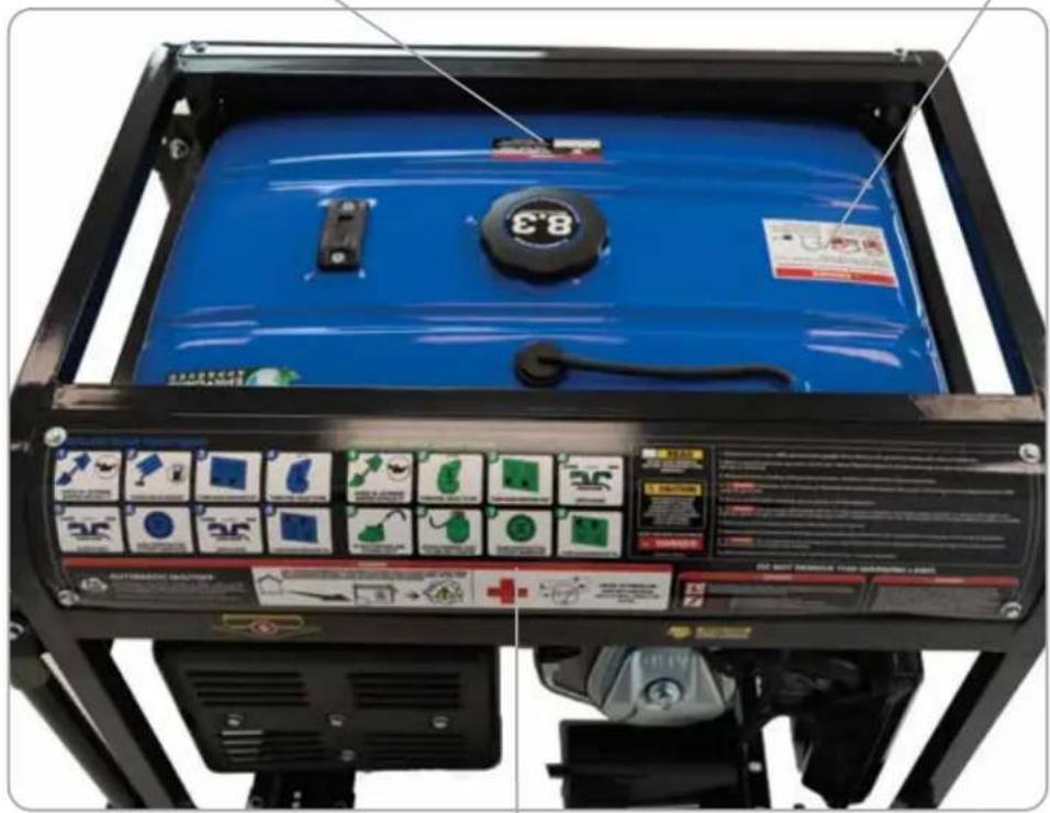
In addition to the above safety notices, please familiarize yourself with the safety and hazard markings on the generator.
DANGER
Using a generator indoors CAN KILL YOU IN MINUTES. Generator exhaust contains carbon monoxide. This is a poison you cannot see or smell.
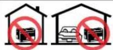
NEVER use inside a home or garage, EVEN IF doors and windows are open.
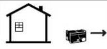
Avoid other generator hazards. READ MANUAL BEFORE USE

CARBON MONOXIDE SAFETY
Carbon Monoxide

Generators are convenient, but they can also be dangerous. All fuel-burning appliances and equipment release a poisonous gas called carbon monoxide.
Carbon monoxide (also known as CO) can be dangerous for humans and pets, even in small amounts, because it blocks oxygen from getting into your body. Carbon monoxide poisoning can lead to death in a very short time. It is odorless, tasteless and invisible, so you may be exposed without knowing it. That is why carbon monoxide is sometimes called "the silent killer."
CO ALERT
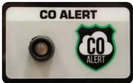
Description
The DuroMax CO ALERT system was created to protect our customers and their families from dangerous carbon monoxide. Just like the detector for your home the CO ALERT tests the air for to keep you safe and healthy.
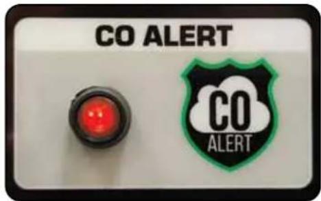
CO Detected
If dangerous carbon monoxide levels are detected:
• The indicator will light red.
• The engine will shutdown.
• The engine will not restart for 5 minutes.
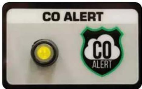
Maintenance Required
If an error in the CO ALERT system is detected the indicator will light yellow. Please contact DuroMax service at 844-DUROMAX for assistance.
ALWAYS READ THE OWNER'S MANUAL FIRST
KNOW THE SYMPTOMS
• HEADACHE • DIZZINESS
• NAUSEA • FATIGUE
• SHORTNESS OF BREATH

natural_image
Yellow curved arrow pointing downward on a gray textured background (no text or symbols)
natural_image
Abstract geometric pattern with diagonal lines and a circular highlight (no text or symbols)POINT FUMES AWAY FROM NEARBY PEOPLE
KEEP IT OUTSIDE AND AWAY FROM DOORS AND WINDOWS
natural_image
Illustration of a charging station with a yellow lightning bolt and antenna (no text or symbols)
As the only safe way to use a portable generator, taking your generator outside is absolutely mandatory to keep your family safe from carbon monoxide. But there's even more you can do. By educating yourself about all carbon monoxide risks, you'll be better prepared to protect your family from this colorless, odorless threat. Visit takeyourgeneratoroutside.com for more information.
TAKE IT OUTSIDE™

CARBON MONOXIDE KILLS
UNIT AND PURCHASE INFORMATION
Serial Number
natural_image
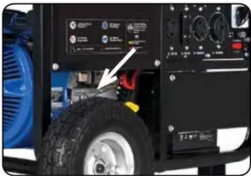
Close-up of a vehicle tire mounted on a black industrial machine with control panel and indicator lights (no visible text or symbols)Serial number
The serial number is located on the engine block, above and to the left of the oil fill.
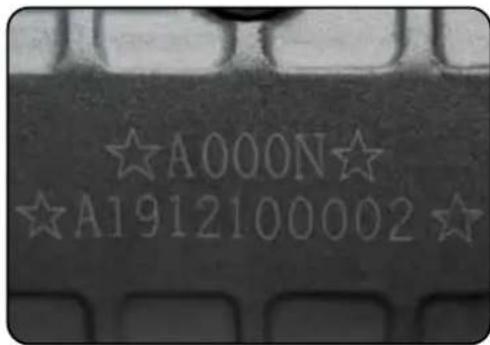
Serial number format
The serial number will be shown in two parts. The engine model, followed by the serial number.
Engine Model:
Serial Number: ____
STAPLE RECEIPT HERE
A purchase receipt may be necessary for warranty parts or service in the future. If you have a paper receipt staple it here for easy reference.
If you purchased the unit online, save the email receipt where you can access it, and record your details here for convenience in the future.
Purchase Date: ____
Order Number: ____
Retailer Name: ____
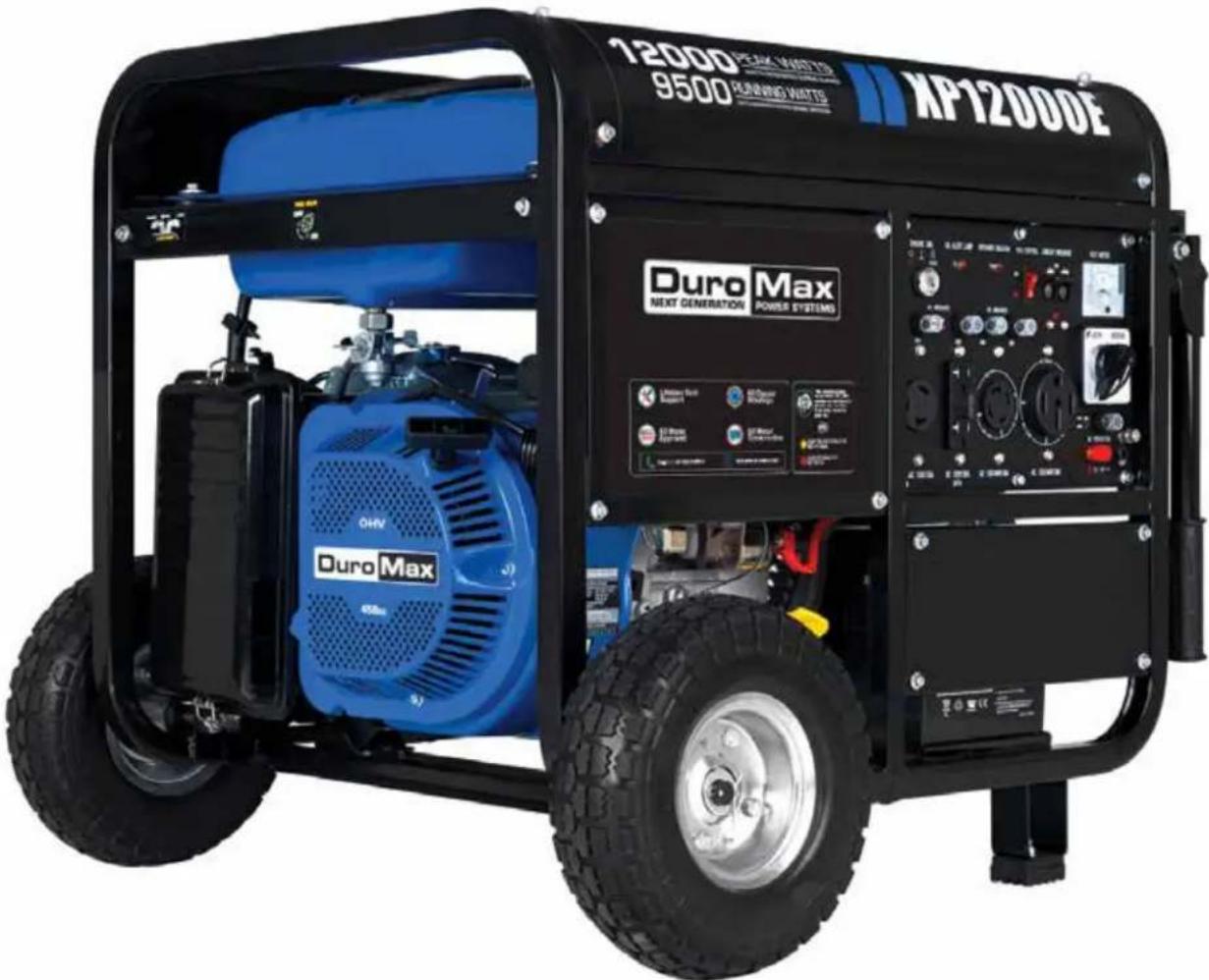
GENERATOR COMPONENTS
To help you get familiar with your new DuroMax generator, please see this component section for easy reference on all the generator's individual features.
GENERATOR COMPONENTS
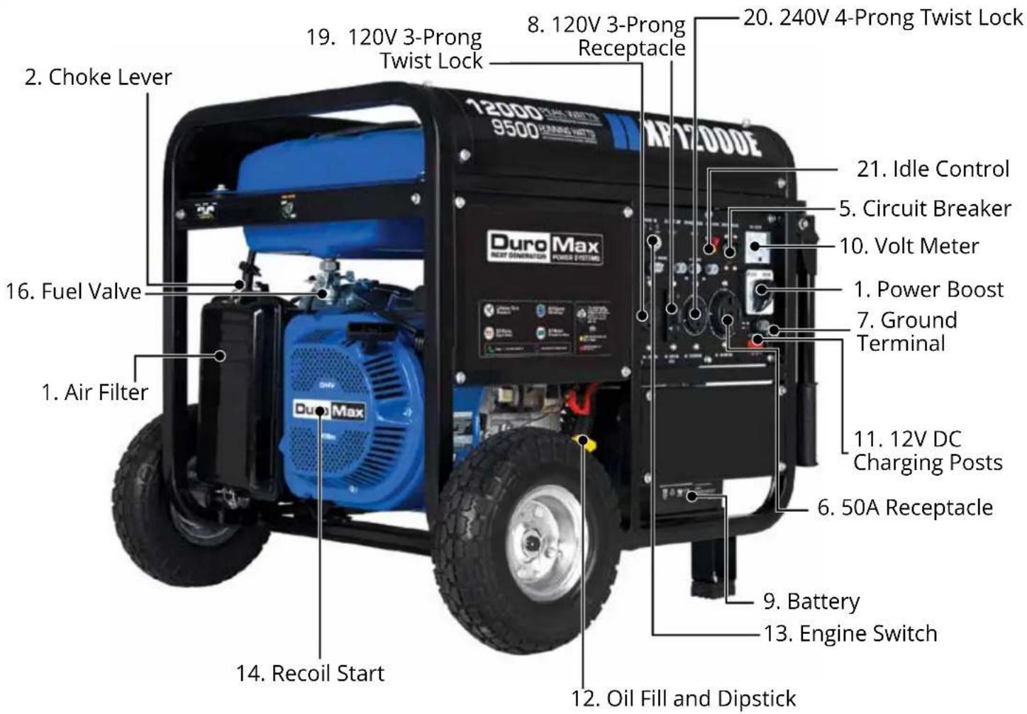
- Air Cleaner - A removable, cleanable, oiled, element that cleans the air going into the engine.
- Choke Lever - Allows the airflow into the carburetor to be restricted to assist in starting the engine.
- Fuel Gauge - Indicates the amount of fuel in the gasoline tank.
- Fuel Cap - Allows access to fill the gasoline tank.
- Circuit Breaker - Resettable switch that protects the generator from electrical overload.
- 50A Receptacle - Use to connect electrical devices that run 120 or 240 Volt, 60Hz, single phase, AC current (NEMA L14-30).
- Ground Terminal - Connect a ground wire here to properly ground the generator.
- 120V 3-Prong Receptacle - Use to connect electrical devices that run 120 Volt, 60 Hz, single phase, AC current (NEMA 5-20).
- Battery - 12V DC battery that powers the electric start system.
- Volt Meter - Provides reading of voltage output.
- 12V DC Charging Posts – DC output for charging batteries or running small DC powered items.
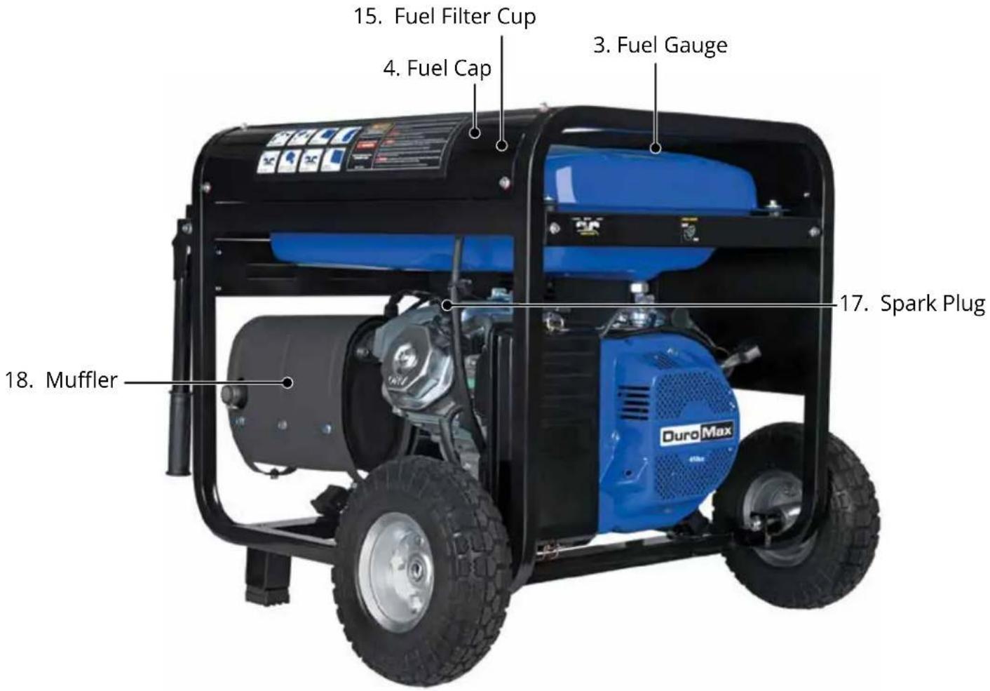
- Oil Fill and Dipstick - Use to add or check the oil.
- Engine Switch - 3 Position Switch to "START", "RUN", or turn "OFF" the generator.
- Recoil Start – Easy pull recoil start to start the engine without the electric start.
- Fuel Filter Cup - Traps dirt and debris in gasoline before it enters the engine.
- Fuel Valve - On/Off Valve that allows fuel into the engine.
- Spark plug – Provides ignition to the engine.
- Muffler - Reduces engine emissions and reduces noise.
- 120V 3-Prong Twist Lock - Use to connect electrical devices that run 120 Volt, 60 Hz, single phase, AC current (L5-30).
- 240V 4-Prong Receptacle - Use to connect electrical devices that run 120 or 240 Volt, 60Hz, single phase, AC current (NEMA 14-50).
- Idle Control - Allows the engine to run at reduced speed when no load is present to save on fuel and reduce noise levels.
■ PACKAGE CONTENTS
Your generator comes with the items listed below. Please check to see that all of the following items are included with your generator.
natural_image
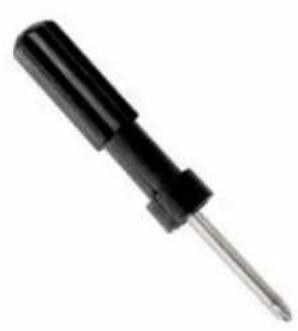
Close-up of a black screwdriver with a metallic tip (no text or symbols visible)Double-Sided Screw Driver
Phillips and slot blade screwdriver used for generator maintenance.

natural_image
Four metallic wrenches arranged vertically (no text or symbols visible)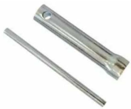
natural_image
Two metallic cylindrical metal rods with circular holes, no text or symbols visibleSpanner Spark Plug Wrench
Assorted wrenches used in generator maintenance and assembly. 10mm/12mm, 13mm/15mm, and 17mm/19mm.
Used in spark plug maintenance, inspection, and installation.

natural_image
Simple curved line drawing resembling a tool or tool (no text or symbols)Oil Funnel w/ Hose
Used to add oil to the generator without messy spills.
natural_image
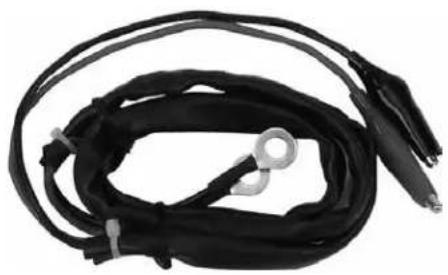
Coiled black cable with two connectors and a metallic ring, isolated on white background (no text or symbols)DC Charge Cables
Used in conjunction with the charging posts to charge 12V automotive style batteries or small DC appliances.
natural_image
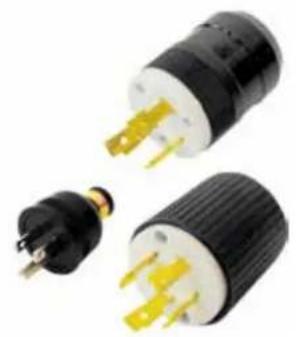
Three black and white electrical plug connectors with gold contacts, shown from different angles (no text or symbols visible)Plug Ends
Plug heads for the receptacles found on the generator are included to make or rewire your own cords.
Note: Actual tools may differ in appearance or design from image shown.
GENERATOR SETUP
Proper setup of your generator will get you going as soon as possible while making sure you and your equipment are safe and cared for.
Duro Max
Step 1 - Remove Shipping Braces
natural_image
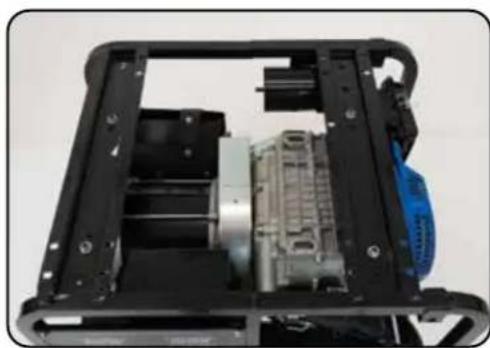
Interior view of a mechanical device showing internal components and housing (no visible text or symbols)1. Unpack
a. Remove the generator from the box.
b. Place the largest piece of packing foam on a flat surface.
c. Flip the generator upside down on the pad.

CAUTION: NEVER attempt this if you have put fuel or oil in the generator.
natural_image
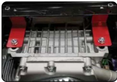
Close-up of a mechanical assembly with red and black components, no visible text or symbols2. Remove braces
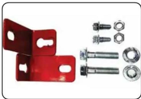
a. The shipping braces prevent engine movement during shipment. Flip the generator over and remove the brightly colored braces between the motor and the frame, and the wood brace under the generator.
natural_image
Collection of red metal bracket components including bolts, nuts, and bolts (no text or symbols visible)
natural_image
Blue trash bin icon with no text or symbolsNote: Shipping braces can be thrown away, they will not be needed again.
■ GENERATOR SETUP (CONTINUED)
Step 2 - Wheel Kit Installation (Optional)
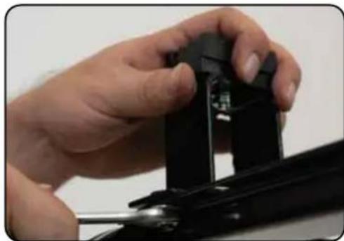
natural_image
Close-up of a hand adjusting a black mechanical component (no visible text or symbols)1. Install support legs
a. Secure the support legs to the frame with the provided lock nuts.
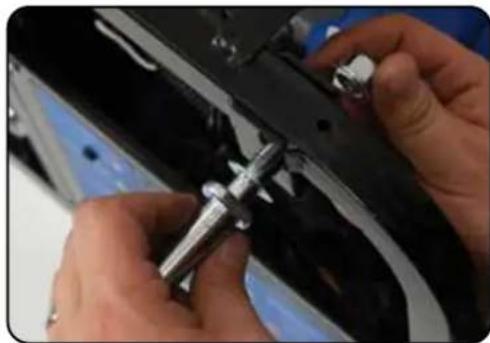
natural_image
Close-up of hands installing a mechanical component with a metal tool (no visible text or symbols)2. Install wheel axles
a. Place the smallest washer onto the wheel axle bolts. b. Insert wheel axle bolts through the frame and secure with the provided nut and wrenches.
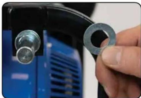
natural_image
Close-up of a hand holding a metal ring attached to a blue industrial component (no visible text or symbols)3. Install inside wheel washers
a. Place one of the large washers onto the axles.
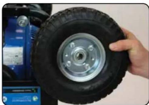
natural_image
Hand holding a black tire with a metallic rim, next to a blue industrial machine (no visible text or symbols)4. Install wheels
a. Place the wheels onto the axles.
natural_image
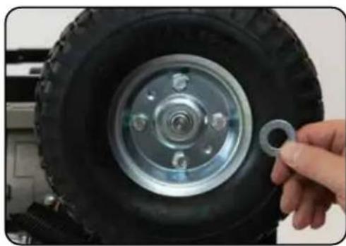
Close-up of a hand holding a small metal ring attached to a black off-road vehicle tire (no text or symbols visible)5. Install outside wheel washers
a. Place the other large washers onto the axles.
natural_image
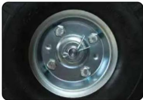
Close-up of a car wheel rim with four bolts and a central hub (no text or symbols visible)6. Install cotter pins
a. Place the cotter pin through the hole at the end of the axle and bend it out to secure the wheel.
natural_image
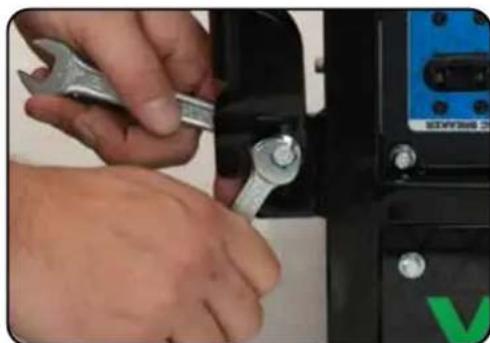
Close-up of hands using a wrench to adjust a mechanical component (no visible text or symbols)7. Install handles
a. Attach the handles to the brackets on the frame using the provided bolts and nuts.

CAUTION: Do not over-tighten the handles, it will prevent free movement.
natural_image
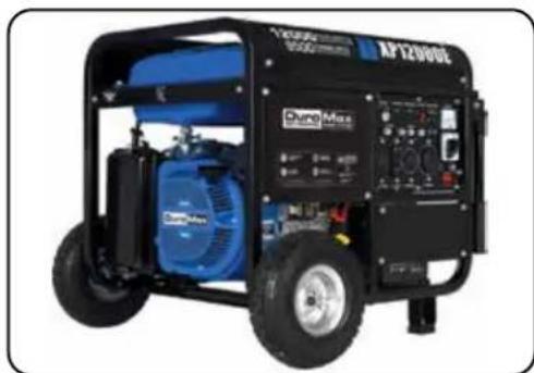
Exterior view of a large outdoor portable gas generator (no visible text or symbols)8. Flip over assembled
a. Flip the assembled generator over onto its wheels and support brackets.
■ GENERATOR SETUP (CONTINUED)
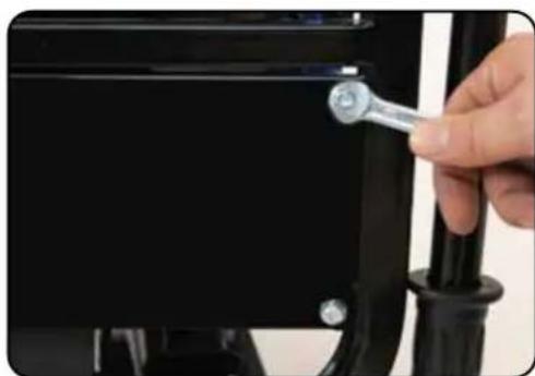
Step 3 - Connect the Battery
natural_image
Close-up of a hand holding a wrench to adjust a black mechanical component (no text or symbols visible)1. Remove the battery cover
a. Remove the battery cover plate using the wrench from the toolkit.
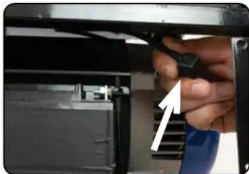
natural_image
Close-up of a hand inserting a component into a device (no visible text or symbols)2. Locate the negative cable
a. Locate the negative battery cable above and behind the battery. One side is connected to ground and the other end needs to be connected to the battery. b. Route the free end to the negative battery terminal.
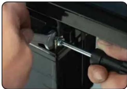
natural_image
Close-up of hands using a screwdriver to adjust or install a mechanical component (no visible text or symbols)3. Connect the negative cable
a. Push the black rubber boot up the wire to expose the connector. b. Securely connect the free end of the battery cable to the negative battery terminal using the screw and nut from the battery with the screwdriver and wrench from the toolkit.
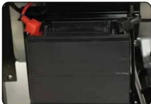
natural_image
Close-up of a black battery pack with red connectors, no visible text or symbols4. Reinstall the battery plate
a. Cover the connected terminal with the black rubber boot. b. Reinstall the battery cover plate using the wrench from the toolkit.
Step 4 - Adding Oil
The generator requires engine oil to operate properly. The generator, when new from the package, contains no oil in the crankcase*. You must add the proper amount of oil before operating the generator for the first time. This amount is equal to the oil capacity of the engine crankcase:
| Model Number XP12000E |
| Engine Oil Capacity 40.5 fl. oz (1.2 L) |

WARNING: Do not apply engine oils with additives or 2-stroke gasoline engine oils; they don't have enough lubrication and may shorten the engine's service life.
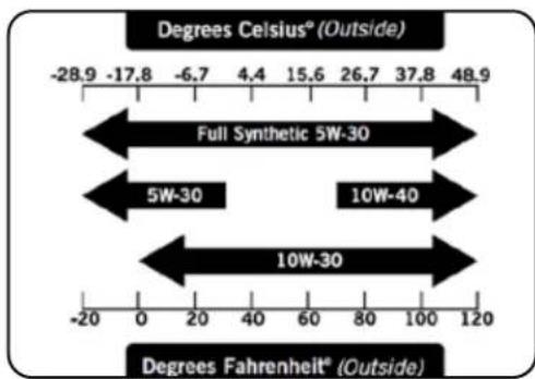
Engine oil recommended: SAE 10W-30.
Viscosity varies with regions and temperatures. Choose your oil viscosity using the chart to the left.
* A small amount of oil from factory testing may be present on arrival.
* Synthetic oil may be used after the 8 hour initial break-in period. Using synthetic oil does not increase the recommended oil change interval. Full synthetic 5W-30 oil will aid in starting in cold temperatures < 5^ (41°F).
natural_image
Close-up of a hand holding a yellow tool interacting with an electrical component (no visible text or symbols)Add oil
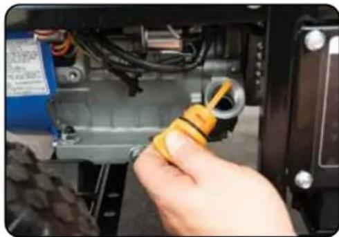
a. Make sure the generator is on a level surface.
b. Unscrew the oil filler/dipstick cap from the engine.
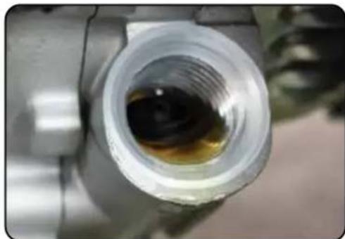
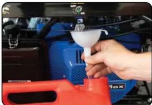
c. Using a funnel, add the appropriate amount of oil into the crankcase. You will know the crankcase is full when the oil level has reached the lower lip of the opening you have just poured the oil into.
d. Replace the oil filler cap.
natural_image
Close-up of a metallic pipe fitting with a dark liquid inside, no visible text or symbols
WARNING: Do not overfill the crankcase. This may damage the motor and shorten the overall life of your generator.
GENERATOR SETUP (CONTINUED)
Step 5 - Adding Gasoline
natural_image
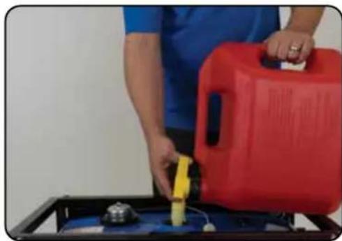
Person pouring liquid into a red gas cylinder on a black tray (no visible text or symbols)Add gasoline
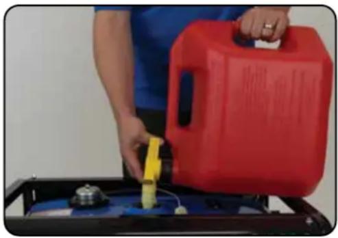
a. Make sure the generator is on a level surface.
b. Unscrew gas cap and set aside (NOTE: the gas cap may be tight and hard to unscrew).
c. Slowly add unleaded gasoline to the fuel tank. Be careful not to overfill. The fuel gauge on the top of the gas tank indicates how much gasoline is in the generator gas tank.
d. Replace fuel cap and wipe up any spilled gasoline with a dry cloth.
| Model Number XP12000E | |
| Gas Tank Capacity 8.3 | US gal. (31 L) |
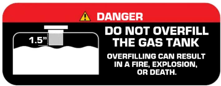

WARNING: Gas can expand. Do not fill the gas tank to the very top. Leave a minimum of 1.5 in open space. Gasoline and gas fumes are highly flammable. Do not fill the tank near an open flame. Always check for fuel spills.
IMPORTANT:
- To ensure that the generator runs smoothly use only FRESH, UNLEADED GAS WITH AN OCTANE RATING OF 87 OR HIGHER.
- Never use an oil/gasoline mixture. Never use old gas.
- Avoid getting dirt or water in the fuel tank.
Gas can age in the tank and make it hard to start up the generator in the future.
• Never store generator for extended periods of time with fuel in the tank.
Step 6 - Grounding the Generator
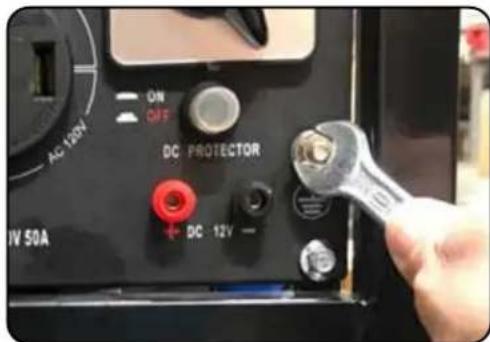
Attach grounding wire
a. Ground the generator by tightening the grounding nut against a grounding wire.
b. Connect the other end to a copper or brass grounding rod that's driven into the earth.
A generally acceptable grounding wire is a No. 12 AWG (American Wire Gauge) stranded copper wire.
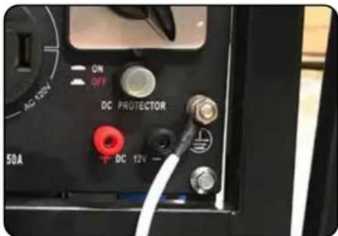
Grounding codes can vary by location. Please contact a local electrician to check the grounding regulations for your area.
Note: If the generator is connected to a home, then it won't be necessary to attach the separate grounding wire and you can opt to use your home ground instead. Please see a certified electrician for further options with grounding your generator.

WARNING: Failure to properly ground the generator can result in electrocution.
High Altitude Operation
At high altitudes, the standard carburetor air/fuel mixture will be too rich. The performance will decrease, and fuel consumption will increase. A very rich mixture will also foul the spark plug and cause hard starting. Operation at an altitude that differs from that at which this engine was certified, for extended periods of time, may increase emissions. High altitude performance can be improved by specific modifications to the carburetor. If you always operate your generator at altitudes above 3,000 feet (900 meters), have a dealer perform this carburetor modification. This engine, when operated at high altitude with the carburetor modifications for high altitude use, will meet each emission standard throughout its useful life. Even with carburetor modification, engine horsepower will decrease by about 3.5% for each 1,000-foot (300-meter) increase in altitude. The effect of altitude on horsepower will be greater than this if no carburetor modification is made.
When the carburetor has been modified for high altitude operation, the air/fuel mixture will be too lean for low altitude use. Operation at altitudes below 3,000 feet (900 meters) with a modified carburetor may cause the engine to overheat and result in serious engine damage.
Duro Max
STARTING THE GENERATOR
If this is not your first time using the generator there are still steps you should take to prepare it for operation each time you use it.
IMPORTANT: At this point, you should be familiar with the procedures described in the first portion of this section entitled "GENERATOR SETUP" If you have not yet read this section, go back and read it now.
BEFORE YOU START YOUR GENERATOR
Step 1 - Check the Oil
natural_image
Close-up of a hand holding a yellow connector into an electrical enclosure (no visible text or symbols)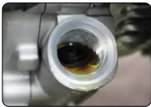
natural_image
Close-up of a metallic pipe fitting with a yellow liquid inside, no visible text or symbolsCheck the oil
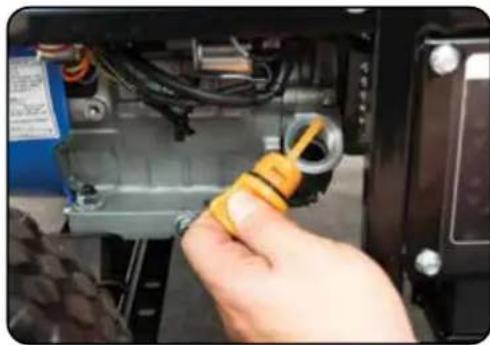
The generator is equipped with an automatic shutoff to protect it from damage due to low oil. Nonetheless, you should check the oil level of the engine before each use to ensure that the engine crankcase has a sufficient amount.
To check the oil level:
a. Make sure the generator is on a level surface.
b. Unscrew the oil filler/dipstick cap.
c. With a dry cloth, wipe the oil off of the stick on the inside of the cap.
d. Insert the dipstick as if you were replacing the cap and then remove it again. There should now be oil on the stick. If there is no oil on the stick, or oil only at the very end of the stick, you should add oil until the engine crankcase is filled (see "Adding Oil" portion of the "Maintenance" section).
e. Be sure to replace the cap when finished checking oil.
| Model Number XP12000E |
| Engine Oil Capacity 40.5 fl. oz (1.2 L) |
Step 2 - Check the Gas Level
natural_image
Person pouring liquid into a red gas cylinder on a blue tray (no visible text or symbols)Check fuel level
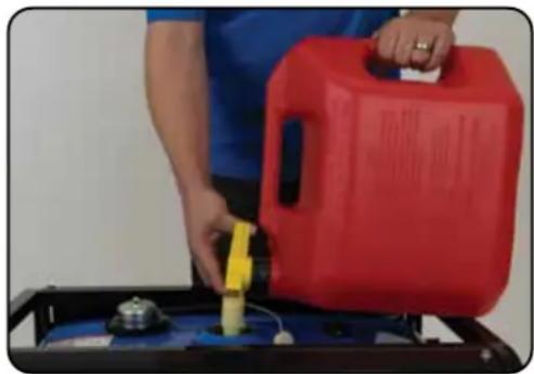
If running the engine on gasoline check to see that there is sufficient gasoline in the fuel tank. The fuel gauge on top of the tank will give a rough estimate of the gasoline level. The gauge will appear white then fill red as the tank is filled.
Note: Fuel gauge may not register with less than 1/3 fuel tank full.

WARNING: Gasoline and gasoline fumes are highly flammable.
- Do not fill the tank near an open flame.
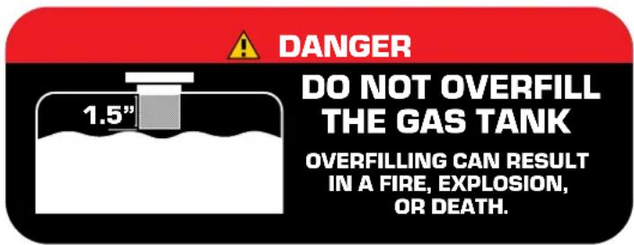
• Always allow the engine to cool for several minutes before refueling. - DO NOT overfill the fuel tank. Fuel expands when shaken or heated. ALWAYS leave 1^1/2 space or more at the top of the tank.
- ALWAYS use fresh fuel or stabilized fuel. Old gasoline (older than 30 days) can cause permanent damage to the fuel system.
• Always check for fuel spills.
■ STARTING THE GENERATOR
Starting the Generator
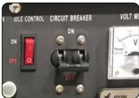
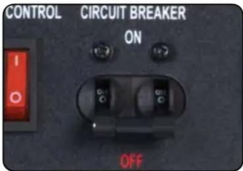
1. Shut breaker OFF
The breaker is located on the right side of the front power panel. Flip the breaker down to prevent accidental load when starting the generator.
natural_image
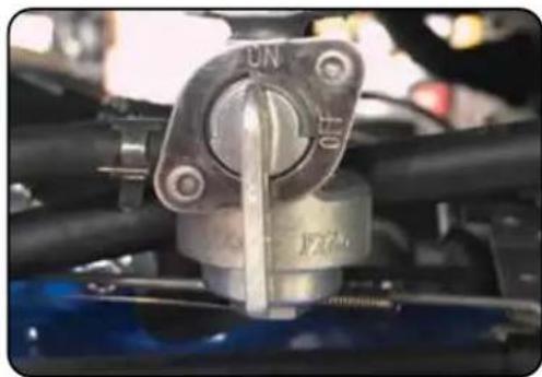
Close-up of a mechanical valve assembly with no visible text or symbols2. Turn gas valve ON
The gas valve is located above the recoil start on the bottom of the fuel tank. Rotate the valve counter-clockwise to the vertical position to turn on the gas supply.
natural_image
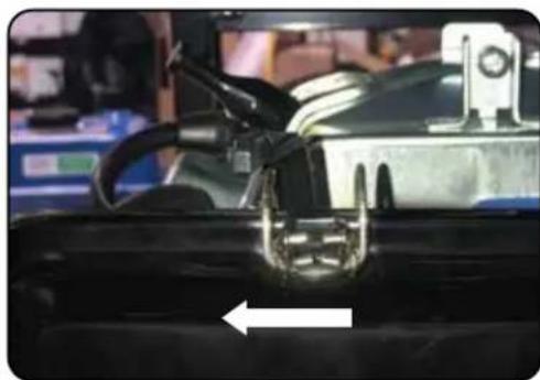
Close-up of a car's front grille with visible mechanical components and a white arrow pointing to a component (no text or symbols)3. Close choke
The choke lever is located above the air filter to the left of the recoil start. Slide the lever to the left to cut the air supply and allow more gas into the engine to start.
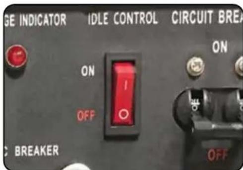
4. Turn idle control OFF
The idle control is located on the top center of the main power panel. Turn the switch "OFF" to prevent the unit from trying to idle down before the engine is warmed up.
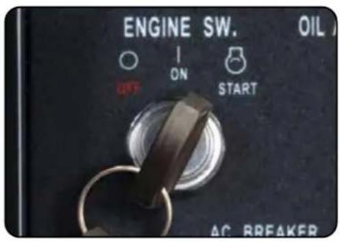
5. Turn engine switch to START
The key switch is located on the left side of the front power panel. Insert the key and turn to the "START" position to start the generator. Allow the key to return to the run position once started.
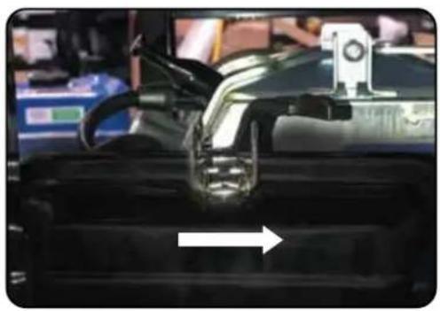
natural_image
Close-up of a car's engine compartment with a white arrow indicating compression or disassembly (no visible text or symbols)6. Open choke
Push the choke to the "OPEN" position as the engine warms up.
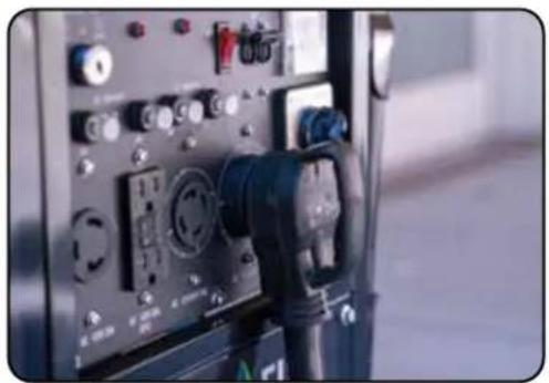
natural_image
Close-up of an electrical testing device with multiple connected components and control knobs (no visible text or labels)7. Turn breaker ON/Connect
The breaker is located on the right side of the front power panel. Flip the breaker up to allow the power to flow to the receptacles. Connect your devices to the receptacles on the front panel. Start with the largest loads first.

CAUTION: Disconnect all electrical loads from the generator before attempting to start!

WARNING: Operating the starter motor for more than 5 seconds can damage the motor. If the engine fails to start, release the switch and wait 10 seconds before operating the starter again.
■ STARTING THE GENERATOR (CONTINUED)
Starting the Generator Using Recoil Start
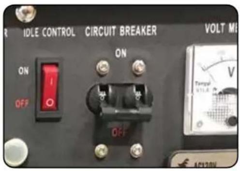
1. Shut breaker OFF
The breaker is located on the right side of the front power panel. Flip the breaker down to prevent accidental load when starting the generator.
natural_image
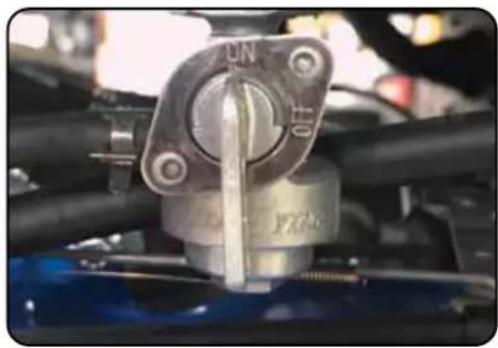
Close-up of a mechanical component with metallic fittings and black pipes (no visible text or symbols)2. Turn gas valve ON
The gas valve is located above the recoil start on the bottom of the fuel tank. Rotate the valve counter-clockwise to the vertical position to turn on the gas supply.
natural_image
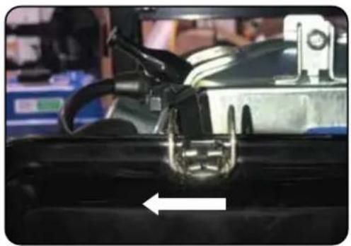
Close-up of a car engine bay with visible mechanical components and a white arrow pointing to a component (no text or symbols)3. Close choke
The choke lever is located above the air filter to the left of the recoil start. Slide the lever to the left to cut the air supply and allow more gas into the engine to start.
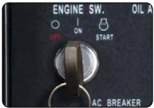
4. Turn engine switch to ON
The key switch is located on the left side of the front power panel. Insert the key and turn to the "ON" position.
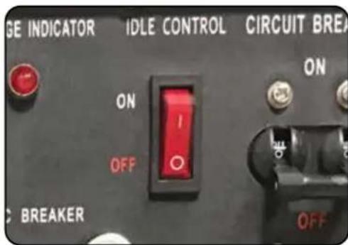
5. Turn idle control OFF
The idle control is located on the top center of the main power panel. Turn the switch "OFF" to prevent the unit from trying to idle down before the engine is warmed up.
natural_image
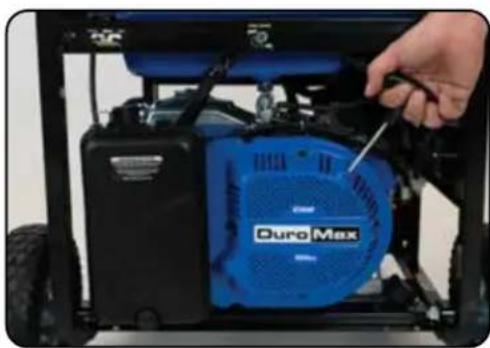
Close-up of a Duro Max electric vehicle engine with a hand adjusting its internal components (no visible text or symbols)6. Pull the recoil start
The recoil start is located on the left side panel next to the air filter. Pull the recoil handle slowly until resistance is felt, then quickly pull the recoil handle until fully extended.

CAUTION: Release the recoil handle only after the cord has retracted. Releasing the recoil handle while extended may cause harm to yourself or your equipment.
natural_image
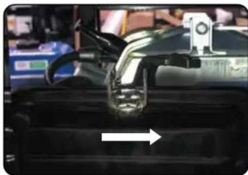
Close-up of a car's front grille with a glass cap and mechanical components, no visible text or symbols7. Open choke
Push the choke to the "OPEN" position as the engine warms up.
natural_image
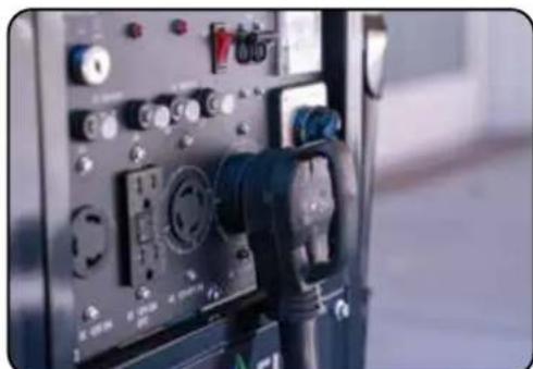
Close-up of an electrical testing device with multiple connected probes and control knobs (no visible text or labels)8. Turn breaker ON/Connect
The breaker is located on the right side of the front power panel. Flip the breaker up to allow the power to flow to the receptacles. Connect your devices to the receptacles on the front panel. Start with the largest loads first.
Duro Max
USING THE GENERATOR
If this is not your first time using the generator, there are still steps you should take to prepare it for operation each time you use it.
IMPORTANT: At this point, you should be familiar with the procedures described in the first portion of this section entitled "GENERATOR SETUP"; if you have not yet read this section, go back and read it now.
AC Usage
- You may connect electrical devices running on AC current according to their wattage requirements.
- The chart below shows the rated and surge wattage of your generator according to its model number.
- The rated wattage corresponds to the maximum wattage the generator can output on a continuous basis.
- The surge wattage corresponds to the maximum amount of power the generator can output for a short period of time. Many electrical devices such as refrigerators require short bursts of extra power, in addition to the rated wattage listed by the device, to stop and start their motors. The surge wattage ability of the generator covers this extra power requirement.
| Fuel Source Rated (Running) Wattage Surge (Peak) Wattage | ||
| Gasoline 9500 12000 | ||
The total running wattage requirement of the electrical devices connected to the generator should not exceed the rated wattage of the generator itself. To calculate the total wattage requirement of the electrical devices you wish to connect, find the rated (or running) wattage of each device. This number should be listed somewhere on the device or in its instruction manual.
If you cannot find this wattage, you may calculate it by multiplying the Voltage requirement by the Amperage drawn: Watts = Volts x Amps. If these specifications are not available, you may estimate the Watts required by your device by using the chart on the next page.
Once you have found the rated wattage requirement of each electrical device, add these numbers to find the total rated wattage you wish to draw from the generator. If this number exceeds the rated wattage of the generator, DO NOT connect all these devices. Select a combination of electrical devices, which has a total rated wattage lower than or equal to the rated wattage of the generator.
| Tool or Appliance Rated | (Running) Watts Additional Surge Watts |
| Electric water heater (40 gal) 4000 0 | |
| Hot plate 2500 0 | |
| Radial arm saw 2000 2000 | |
| Electric Stove 1500 0 | |
| Circular Saw 1500 1500 | |
| Air compressor (1 HP) 1500 3000 | |
| Window air conditioner 1200 1800 | |
| Miter saw 1200 1800 | |
| Microwave 1000 2000 | |
| Well water pump 1000 1500 | |
| Reciprocating saw 960 1040 | |
| Sump pump 800 1200 | |
| Refrigerator freezer 800 1200 | |
| Furnace blower | 800 1300 |
| Computer | 800 0 |
| Electric drill | 600 900 |
| Television | 500 0 |
| Deep freezer | 500 800 |
| Garage door opener | 480 600 |
| Stereo | 400 0 |
| Box fan | 300 600 |
| Clock radio | 300 0 |
| Security system | 180 0 |
| DVD Player | 100 0 |
| Common light bulb | 75 |

CAUTION: The generator can only run at its surge wattage capacity for a very short time. Connect only electrical devices requiring a rated (running) wattage equal to or less than the rated wattage of the generator. Never connect devices requiring a rated wattage equal to the surge wattage of the generator.
NOTE: The above wattage figures are estimates only.
Try to check the wattage listed on your electrical devices before consulting this chart.
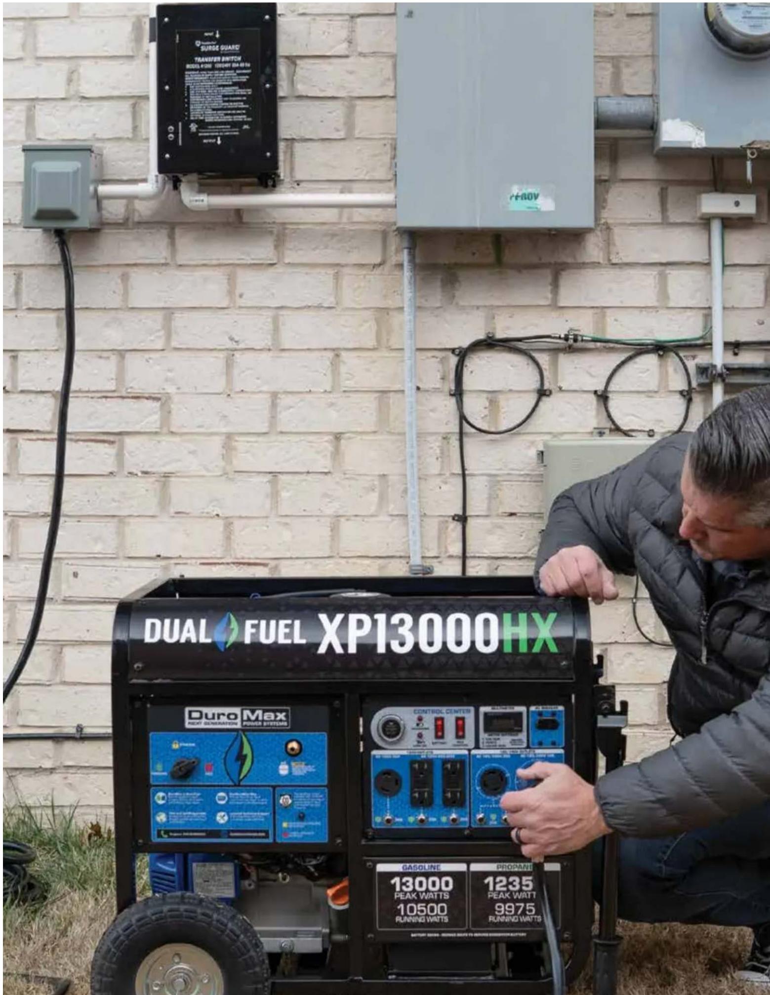
Connecting the Generator to a Home
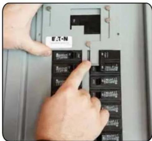
Interlock kit
- Choose what circuits you want to run.
- Requires an electrician to install, but you have the flexibility of switching up your circuits depending on your power needs.
- More hands-on, and some electrical knowledge is needed so you don't overload the generator.
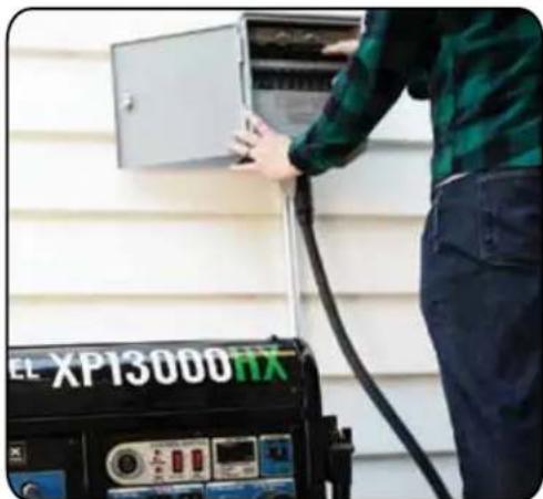
natural_image
Person operating a power supply unit next to an open electrical cabinet (no visible text or symbols)Transfer switch
- Automatically switches power over to your generator during an outage. Requires an electrician to install.
- Once you choose which circuits you want to power, you're locked into your configuration.
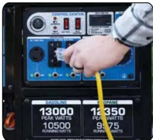
Extension cords
• The most straightforward and affordable option.
- Zero commitment, no installation needed: Simply plug in your appliances and go!
- Perfect for renters, RV/camping trips, and power on the job-site.
■ USING THE GENERATOR (CONTINUED)
Connecting a Load to the Generator
NOTE: Be sure to attach devices to the correct receptacle (outlet).
• 120V devices can be directly connected to the 120V ONLY receptacles.
• 120V devices can be connected to the 120/240V receptacle using an appropriate adapter.
• 240V devices can ONLY be connected to the 240V receptacle.

CAUTION: Do not connect 50 Hz or 3-phase loads to the generator.
natural_image
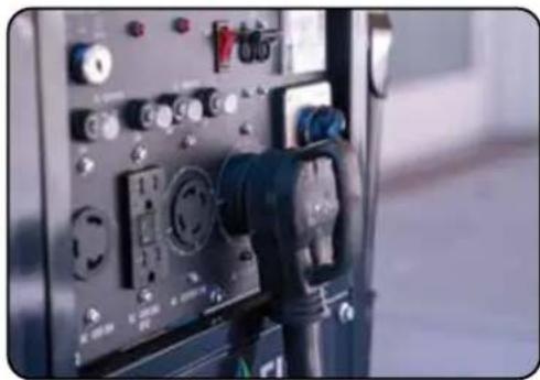
Close-up of an electrical testing device with control knobs and dials (no visible text or symbols)1. Plug in devices
Plug in devices to the appropriate receptacle. When using the generator balance the load as closely as possible. Placing more load on one side of the circuit will reduce the breaker trip period.
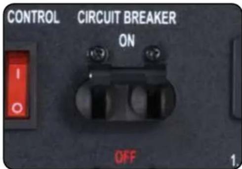
2. Turn breaker ON
Flip the circuit breaker up to the ON position to allow power to the receptacles.

natural_image
Exterior night view of a two-story residential house with illuminated windows and a stone staircase in front (no signage or text visible)3. Turn on connected devices
Start or turn on appliances starting with the biggest loads first.
Choosing the Right Power Cord
Long or thin cords can drain the power provided to an electrical device by the generator. When using such cords, allow for a slightly higher rated wattage requirement for the electrical device. See the table below for recommended cords based on the power requirement of the electrical device.
| DEVICE REQUIREMENTS WIRE GA | UGE BY LENGTH (ft.) | |||||
| AMPS | WATTS (120/240V) 10 25 50 100 150 | |||||
| 5 600 | /1200 18 16 14 12 10 | |||||
| 10 120 | 00/2400 16 14 12 12 10 | |||||
| 15 180 | 00/3600 14 14 12 12 10 | |||||
| 20 240 | 00/4800 12 12 12 10 10 | |||||
| 25 300 | 00/6000 12 10 10 10 8 | |||||
| 30 360 | 00/7200 10 10 10 8 NR | |||||
| 40 480 | 00/9600 8 8 6 6 NR | |||||
| 50 600 | 00/12000 6 6 6 NR NR | |||||
| *NR = NOT RECOMMENDED *Gauge based on twisted copper wire | ||||||
From home back up to just running your electric edger and everything in-between DuroMax has the power cord for you. All DuroMax cords are 100% twisted copper wire for maximum life and reliability.
| Length | 120V 15A | 240V 30A | 240V 50A | ||||
| 14 Gauge | 12 Gauge 10 Gauge | 6 Gauge | |||||
| Single Outlet | Single Outlet | Triple Outlet | Single Outlet | Triple Outlet | L14-30P/L14-30R | 14-50P/CS6364 | |
| 10 ft | XP3010GC | ||||||
| 15 ft | XP5015GC | ||||||
| 25 ft | XPC14025A | XPC12025A | XPC12025C | XPC10025A | XPC10025C | XP3025GC | XP5025GC |
| 50 ft | XPC12050C | XPC10050A | XPC10050C | XP3050GC | XP5050GC | ||
| 100 ft | XPC12100A | XPC12100C | XPC10100A | XPC10100C | |||
■ USING THE GENERATOR (CONTINUED)USING TH
DC Usage
natural_image
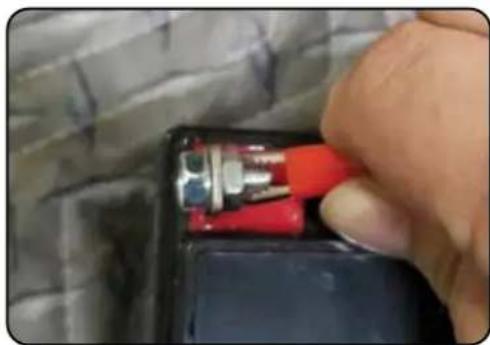
Close-up of a hand inserting a red and black plastic component into a black box, with no visible text or symbols.1. Connect the battery
Connect one charging wire to the positive terminal on the battery and the other charging wire to the negative terminal on the battery.
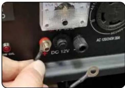
2. Connect positive receptacle
Connect the free end of the positive wire to the positive receptacle (outlet) on the generator.
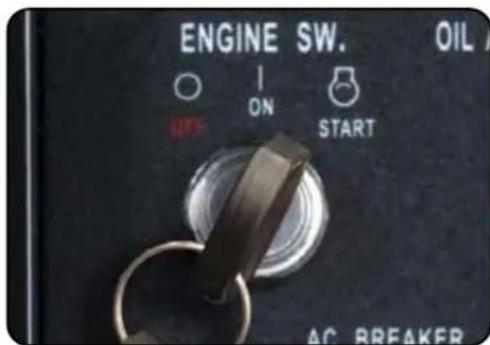
3. Start generator
The start switch is located on the left side of the front power panel. Insert key and move to the start position to start the generator. Allow the switch to return to the run position once started.
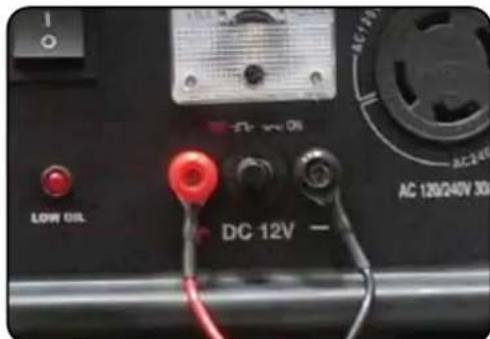
4. Connect negative receptacle
Carefully connect the free end of the negative wire to the negative receptacle on the generator.
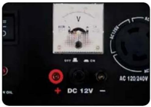
5. Disconnecting battery
When disconnecting, always disconnect the wires from the generator first to avoid a spark.

CAUTION: The DC receptacle is for recharging 12 Volt automotive-type batteries only. Do not connect any other device to this receptacle.

CAUTION: Never try to jump start a car with your generator.

DANGER: Stored batteries emit highly explosive hydrogen gas when charged. Batteries also contain acid, which can cause severe chemical burns.

DANGER: Do not allow open flames or cigarettes nearby for several minutes after charging a battery.

DANGER: Always wear protective goggles and rubber gloves when charging a battery.

DANGER: If battery acid gets on your skin, flush with water. If battery acid gets in your eyes, flush with water and call a physician immediately.

DANGER: If battery acid is swallowed, drink large quantities of milk and call a Physician immediately.
■ USING THE GENERATOR (CONTINUED)USING TH
Voltage Selector Switch
This generator features Power Boost Technology, which gives the user the ability to double the power in the generator for more heavy duty applications.
The voltage selector switches the dual 120V AC windings of the generator to produce "120V ONLY" or "120/240V". If a 240V appliance is connected to the 4-prong receptacle, the switch must be in the "120/240V" position. If only 120V appliances are being connected to the generator select the "120V ONLY" position to double the 120V amperage and automatically balance the load.


WARNING: Only change the voltage selector switch with the main AC circuit breaker OFF. The generator can be seriously damaged if the voltage selector switch is changed with the breaker ON.
Idle Control Usage
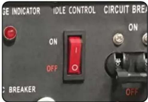
Idle control
The idle control feature lowers the RPM of the generator when there is no load to save gas and decrease engine noise.
When a load is applied, the engine will resume normal speed to provide usable power.
Turn on the idle control when using intermittent loads like power tools and air compressors.
The idle control feature is designed for gasoline only use.

WARNING: Power is unusable when idle control is engaged.
- DO NOT use the idle control function when using the generator for backup house power.
- Idle control function will cause massive fluctuations in voltage and hertz.
- Low amperage loads may not trigger the idle up function.
STOPPING THE GENERATOR
This section will cover the recommended shut off procedure for stopping the generator on various fuels.
Duro Max
■ STOPPING THE GENERATOR
Shutting Down the Generator
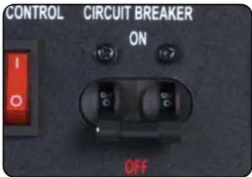
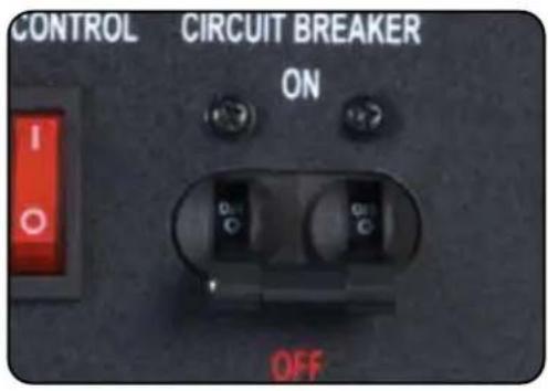
1. Turn the main breaker OFF
Move the main breaker to the "OFF" position.
natural_image
Exterior view of a DureMax portable gas generator (no visible text or symbols on body)2. Run the generator
Allow the generator to run for 3-5 minutes.
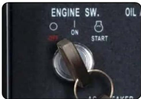
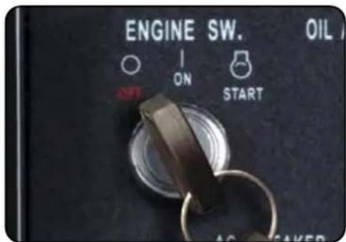
3. Turn the key switch OFF
Turn the key switch counter-clockwise to the "OFF" position to shut the generator off.
natural_image
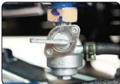
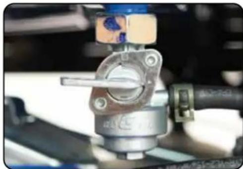
Close-up of a mechanical component with metallic housing and blue components, no visible text or symbols4. Turn fuel valve OFF
Turn the fuel valve clockwise to the horizontal position to shut off the flow of gasoline to the carburetor.
Duro Max
MAINTENANCE AND CARE
Proper maintenance and storage of your generator is essential to ensure trouble free use of your generator when you need it.
By following the maintenance and care requirements, you can keep your generator running smooth and efficient for years to come.
MAINTENANCE AND CARE
Proper routine maintenance of your generator is essential for safe, economical, and trouble-free operation. It will also help reduce air pollution.

WARNING: Improper maintenance, or failure to correct a problem before operation, can cause a malfunction in which you can be seriously injured or killed. Always follow the inspection, maintenance recommendations, and schedules in this instruction manual.
• Make sure the engine is off before you begin any maintenance or repairs.
- Let the engine and exhaust system cool before touching.
- To reduce the possibility of fire or explosion, be careful when working around gasoline. Use only a nonflammable solvent, not gasoline, to clean parts. Keep cigarettes, sparks, and flames away from all fuel-related parts.
Maintenance Schedule
Remember that this schedule is based on the assumption that your machine will be used for its designed purpose. Sustained high-load, high-temperature operation, or use in unusually wet or dusty conditions, will require more frequent service.
| SERVICE | EVERY USE | 1ST MO. OR 8 HRS. (BREAK IN) | EVERY 3 MO. OR 50 HRS. OF HEAVY USE | EVERY 6 MO. OR 100 HRS. OF NORMAL USE | EVERY 12 MO. OR 300 HRS. | EVERY 3 YRS. OR 500 HRS. |
| ENGINE OIL CHECK CHANGE CHANGE | ||||||
| AIR CLEANER CHECK CHECK CHANGE CHANGE | ||||||
| SEDIMENT CUP | CLEAN CLEAN | |||||
| SPARK PLUG CLEAN / | ADJUST | CLEAN / ADJUST | ||||
| SPARK ARRESTOR | CHECK CLEAN | |||||
| IDLE SPEED CHECK / | ADJUST | |||||
| VALVE CLEARANCE | CHECK / ADJUST | |||||
| FUEL TUBE CHECK CHECK / | REPLACE | |||||
| FUEL TANK / FILTER | CLEAN | |||||
| COMBUSTION CHAMBER | CLEAN | |||||
Break-In Period
As the best practice for any new combustion motor it's recommended to perform the break in procedure as follows:
- Run the generator for the first 6-8 hours on conventional oil, then change the oil. After the break-in period synthetic oil may be used.
- During the break in period of the first 6-8 hours keep the generator load under 50% for optimal results.
- Check and clean the air filter if necessary after the break-in period.
Maintenance Log
As a best practice it's recommended to keep a log of the generator hours and maintenance to ensure your generator is always operating to its full potential.
| Date Generator Hours Maintenance Performed | ||
■ MAINTENANCE AND CARE (CONTINUED)
Checking the Oil
natural_image
Close-up of a hand inserting a yellow plug into a mechanical component (no visible text or symbols)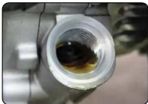
natural_image
Close-up of a metallic pipe fitting with a dark liquid inside, no visible text or symbolsCheck the oil
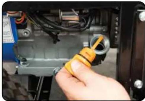
The generator is equipped with an automatic shutoff to protect it from damage due to low oil; nonetheless, you should check the oil level of the engine before each use to ensure that the engine crankcase has a sufficient amount.
To check the oil level:
a. Make sure the generator is on a level surface.
b. Unscrew the oil filler/dipstick cap.
c. With a dry cloth, wipe the oil off of the stick on the inside of the cap.
d. Insert the dipstick as if you were replacing the cap and then remove it again. There should now be oil on the stick. If there is no oil on the stick, or oil only at the very end of the stick, you should add oil until the engine crankcase is filled (see "Adding Oil" portion of the "Maintenance" section).
e. The oil will be visible in the oil fill spout when full.
f. Be sure to replace the cap when finished checking oil.
| Model Number XP12000E |
| Engine Oil Capacity 40.5 fl. oz (1.2 L) |
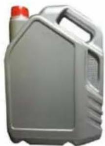
Changing the Oil
natural_image
Gray plastic container with red lid and handle, no visible text or symbols
CAUTION: Worn out or dirty oil does not cool the generator properly and can lead to catastrophic engine damage.
In addition to regular oil changes, it is necessary to drain the oil from the crankcase if it has become contaminated with water or dirt.
natural_image
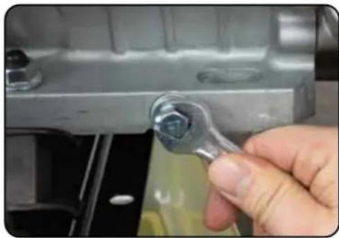
Close-up of a hand holding a small metal wrench against a metallic mechanical component (no text or symbols visible)1. Remove drain plug
Using a 12 mm hex wrench, unscrew the oil drain plug, which is located on the crankcase underneath the oil filler/dipstick cap.
Allow all the oil to drain from the generator.
natural_image
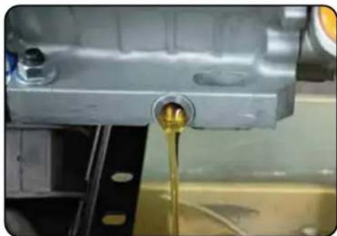
Close-up of a mechanical component with a yellow liquid being poured into it, no visible text or symbols2. Drain oil
Drain oil into an approved oil disposal container. Contact your local auto parts store for information on oil disposal.
natural_image
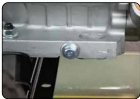
Close-up of a mechanical component with a metallic bracket and screw-like features (no visible text or symbols)3. Replace drain plug
Replace the oil drain plug and tighten with a 12 mm hex wrench.
■ MAINTENANCE AND CARE (CONTINUED)
Cleaning the Air Filter

Routine maintenance of the air cleaner helps maintain proper airflow to the carburetor. Check that the air cleaner is free of excessive dirt after every use.

CAUTION: Improper maintenance may cause less air to enter the engine or dirty air to enter the engine causing overheating and engine wear.
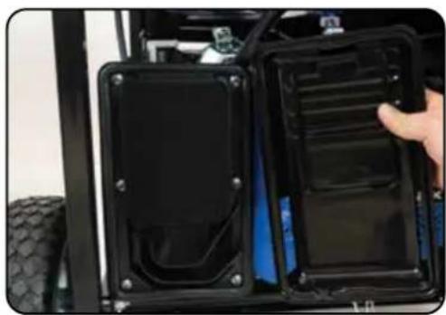
natural_image
Close-up of a black automotive electronic device with two side panels, one being handled by a hand (no visible text or symbols)1. Remove the filter cover
Release the clips on the top and bottom of the cover and remove the filter cover.
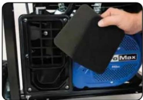
natural_image
Close-up of a hand holding a black square patch over a blue Max air conditioner fan (no visible text or symbols)2. Remove filter
Remove the sponge-like elements from the casing.
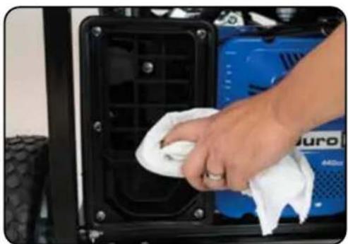
natural_image
Close-up of a hand cleaning a blue Juro vehicle engine compartment with a cloth (no visible text or symbols)3. Clean out filter casing
Wipe the dirt from inside the empty air cleaner casing.
natural_image
Close-up of a hand pouring liquid from a bottle into a clear container, with a black plastic bottle in the background (no visible text or symbols)4. Wash cleaner element
Wash the sponge-like elements in household dish detergent and warm water.
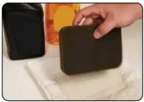
natural_image
Hand holding a black rectangular object on a white surface, with another black container and orange bottle in the background (no visible text or symbols)5. Dry cleaner element
Pat dry on a dry cloth and allow the elements to dry completely.
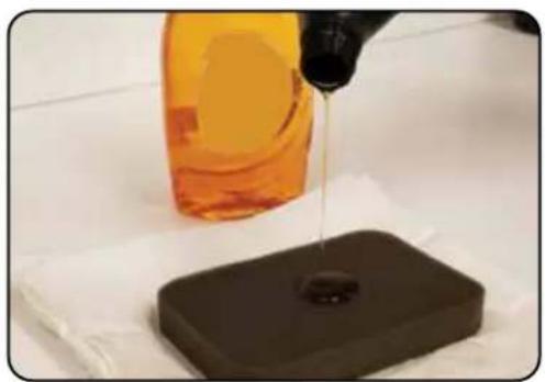
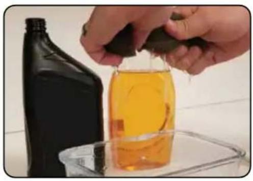
natural_image
Close-up of a bottle pouring liquid into a dark container on a white surface (no text or symbols visible)6. Add engine oil to elements
Soak the dry elements in a small amount of engine oil. Ring out any excess oil.
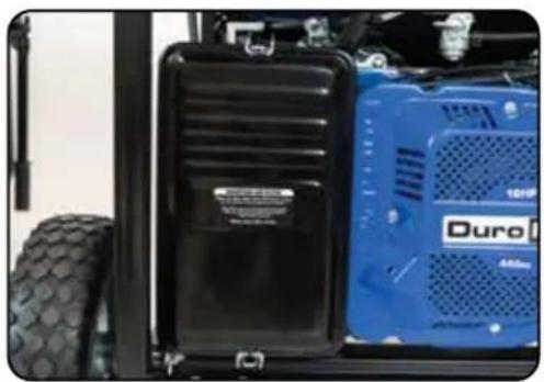
natural_image
Close-up of a blue Duro electric vehicle front panel with visible tire and vent, no text or symbols on the main body.7. Replace elements in casing
Replace the sponge-like elements in the air cleaner casing and replace the cover.
■ MAINTENANCE AND CARE (CONTINUED)
Spark Plug Maintenance

The spark plug is important for proper engine operation. A good spark plug should be intact, free of deposits, and properly gapped.

CAUTION: Improper maintenance may cause reduced fuel economy, misfires, trouble starting, or damage to the spark plug threads.
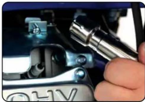
natural_image
Close-up of a hand using a tool to adjust or install a car body panel (no visible text or symbols)1. Remove spark plug cap
Pull on the spark plug cap to remove it.
natural_image
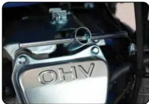
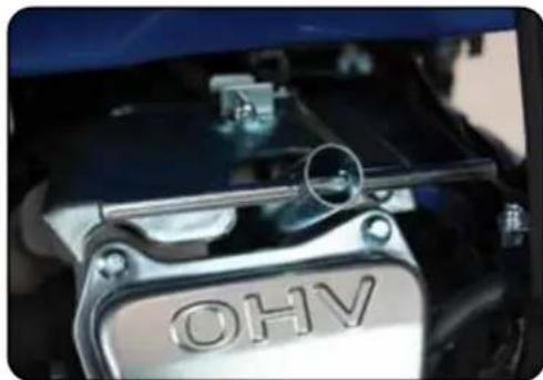
Close-up of a metallic automotive component labeled 'OHV' with a metal handle and circular lens (no readable text beyond label)2. Remove spark plug
Unscrew the spark plug from the generator using the spark plug wrench included with this product.
natural_image
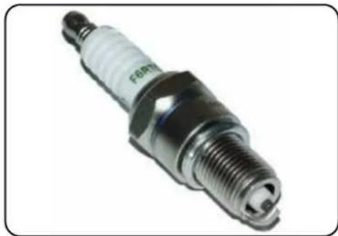
Close-up of a standard spark plug with metallic threaded body and white plastic cap (no visible text or symbols)3. Inspect spark plug
Visually inspect the spark plug. If it is cracked or chipped, discard and replace it with a new spark plug. We recommend using an F6RTC spark plug such as NGK BPR6ES.
natural_image
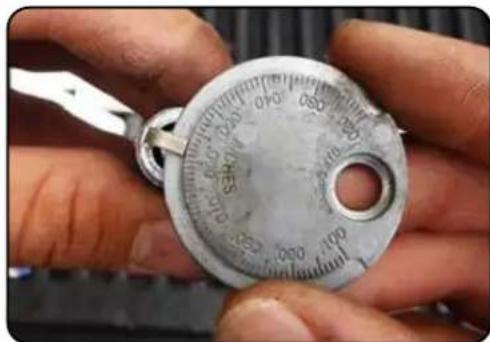
Close-up of hands holding a metallic analog dial with measurement markings (no readable text or symbols)4. Measure plug gap
Measure the plug gap with a gauge. The gap should be 0.7-0.8 mm (0.028-0.031 in).
natural_image
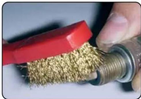
Close-up of a hand using a red tool to cut a textured, coiled metal component (no text or symbols visible)5. Clean and re-gap
If you are re-using the spark plug, use a wire brush to clean any dirt from around the spark plug base and then re-gap the spark plug.
natural_image
Close-up of a car engine bay with visible 'OHV' branding and mechanical components (no readable text beyond label)6. Install spark plug
Screw the spark plug back into its place on the generator using the spark plug wrench.
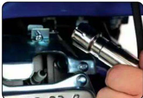
natural_image
Close-up of a hand using a tool to adjust or install electronic components (no visible text or symbols)7. Replace spark plug cap
Replace the spark plug cap.
■ MAINTENANCE AND CARE (CONTINUED)
Emptying the Gas Tank
natural_image
Person pouring liquid into a red gas canister on a tray (no visible text or symbols)If you have been using gasoline in your generator, before storing your generator for extended periods of time you should drain your generator fuel tank of gasoline.

CAUTION: Do not store fuel from one season to another. Gasoline sold at the pump today contains additives such as ethanol that even when stored properly may damage the fuel system components.
natural_image
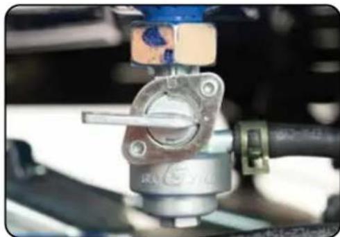
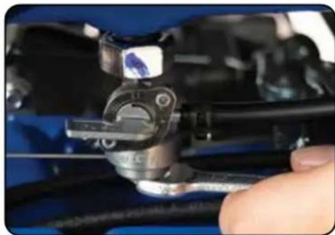
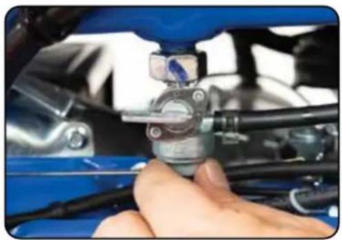
Close-up of a mechanical assembly with a metallic component and a blue tool, no visible text or symbols1. Shut fuel valve OFF
Turn the fuel valve to the "OFF" position.
natural_image
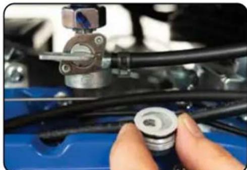
Close-up of a hand adjusting a mechanical component with tools and cables (no visible text or symbols)2. Remove fuel filter cup
Remove the fuel filter cup (see "Removing the Fuel Filter Cup" later in this section).
natural_image
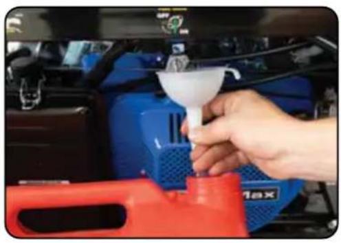
Close-up of hands holding a small mechanical component mounted on a blue car hood (no visible text or symbols)3. Empty fuel filter cup
Empty the fuel filter cup of any fuel.
natural_image
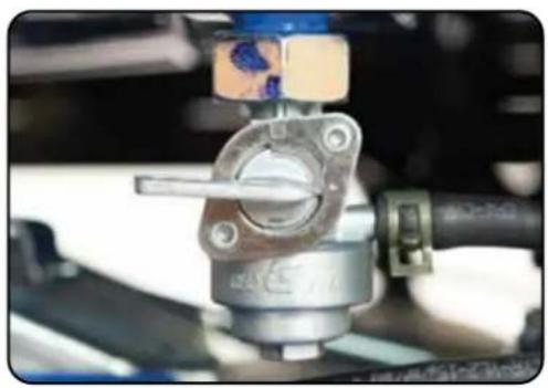
Close-up of a hand pouring liquid into a blue car engine compartment with a red filter cover (no visible text or symbols)4. Drain gas from the generator
With a funnel underneath the fuel valve to catch the gas, turn the fuel valve to the "ON" position. Drain all the gas from the generator.
natural_image
Close-up of a mechanical valve assembly with metallic housing and blue components (no visible text or symbols)5. Shut fuel valve OFF
Turn the fuel valve to the "OFF" position.
natural_image
Close-up of a hand adjusting a mechanical component with blue and black parts (no visible text or symbols)6. Replace fuel filter cup
Reinstall the fuel filter cup.
natural_image
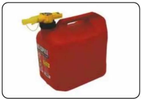
Red fire extinguisher with yellow handle and label (no visible text or symbols on body)7. Store emptied gas
Store the emptied gasoline in a suitable place and add fuel stabilizer to keep fuel fresh and usable.
■ MAINTENANCE AND CARE (CONTINUED)
Cleaning the Fuel Filter Cup
natural_image
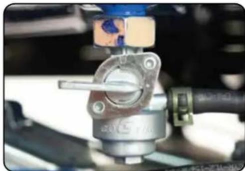
Close-up of a mechanical assembly with a metallic component and a blue tool, no visible text or symbols1. Shut fuel valve off
Turn the fuel valve to the "OFF" position.
natural_image
Close-up of hands adjusting a mechanical component on a blue car hood (no visible text or symbols)2. Remove fuel filter cup
Unscrew the fuel filter cup from the fuel valve using a wrench.
natural_image
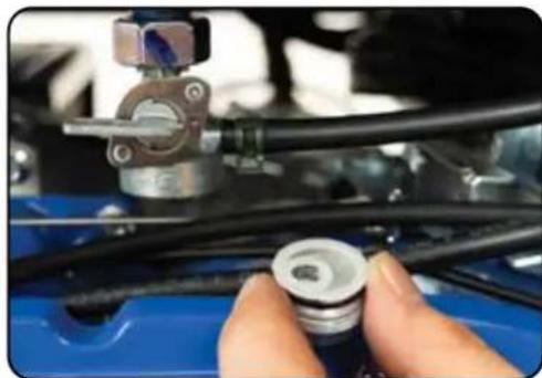
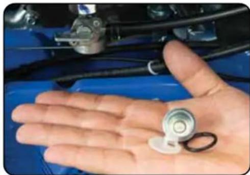
Close-up of a hand holding a small white and black component next to a blue car engine compartment (no visible text or symbols)3. Clean filter cup
Clean the cup of all sediment using a rag or brush.
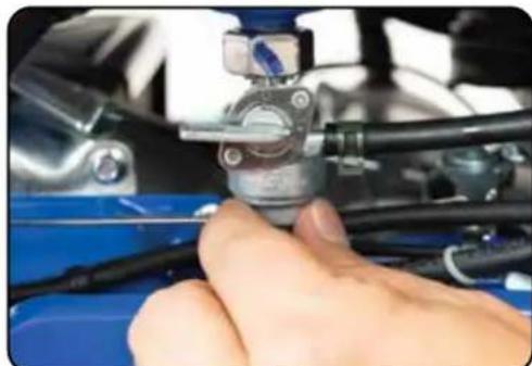
natural_image
Close-up of a hand adjusting a mechanical component with blue and black parts (no visible text or symbols)4. Replace fuel filter cup
Reinstall the fuel filter cup.
Transporting the Generator
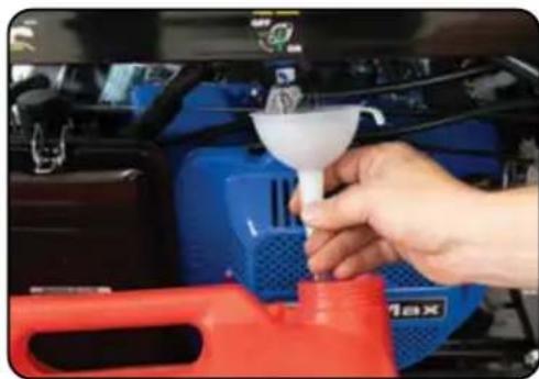
natural_image
Close-up of a hand pouring liquid into a blue car engine compartment with a red filter hood (no visible text or symbols)1. Empty the gas tank
Fully drain your gas tank as shown in "Emptying the Gas Tank" on page 62-63.
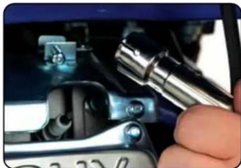
natural_image
Close-up of a hand using a tool to adjust or install a mechanical component, no visible text or symbols2. Disconnect the spark plug
Pull on spark plug cap to disconnect spark plug from ignition wire.

CAUTION: Do not obstruct any ventilation openings and keep the generator in a cool dry area.

CAUTION: Never place any type of storage cover on the generator while it is still hot.
Duro Max
■ MAINTENANCE AND CARE (CONTINUED)
Storing the Generator for Use Within 30 Days
1. Turn breaker OFF and run
Turn OFF the main breaker and allow the generator to run for 3-5 minutes.
natural_image
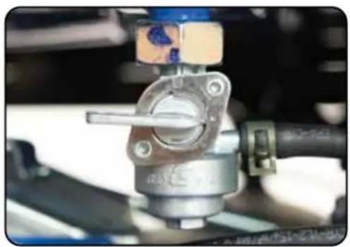
Close-up of a mechanical assembly with a metallic component and a blue tool, no visible text or symbols2. Shut fuel valve OFF and run dry
Shut the fuel valve "OFF" and allow generator to run until it stalls out.
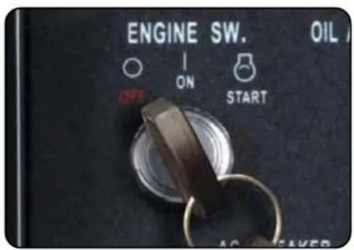
3. Turn the key switch OFF
Turn the key switch counter-clockwise to the "OFF" position to shut the generator off.
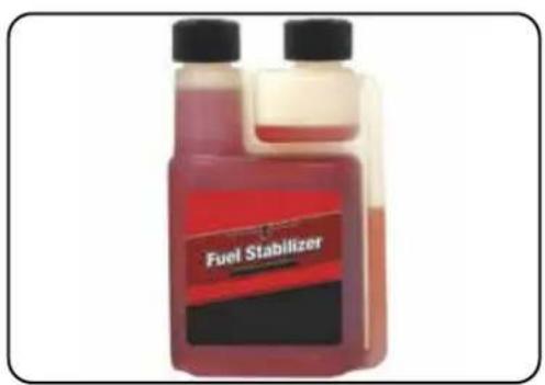
4. Add fuel stabilizer and store
Add fuel stabilizer to gas remaining in tank, and store generator.
■ MAINTENANCE AND CARE (CONTINUED)
Storing the Generator for Longer Than 30 Days
1. Turn breaker OFF and run
Turn OFF the main breaker and allow the generator to run for 3-5 minutes.
natural_image
Close-up of a mechanical assembly with a metallic component and blue components (no visible text or symbols)2. Shut fuel valve OFF and run dry
Shut the fuel valve "OFF" and allow generator to run until it stalls out.
3. Turn the key switch OFF
Turn the key switch counter-clockwise to the "OFF" position to shut the generator off.
natural_image
Close-up of a hand pouring liquid into a car engine compartment with blue and red components (no visible text or symbols)4. Empty the gas tank
Fully drain your gas tank as shown in "Emptying the Gas Tank" on page 62-63.
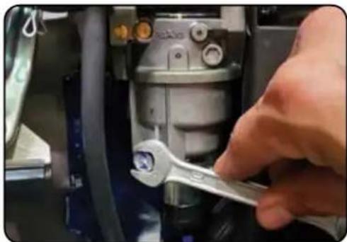
natural_image
Close-up of a hand using a wrench to adjust or install a mechanical component (no visible text or symbols)5. Drain the carburetor
Remove drain bolt from carburetor and drain small amount of fuel in carburetor bowl.
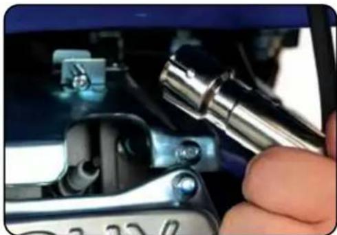
natural_image
Close-up of a hand using a wrench to adjust mechanical parts (no visible text or symbols)6. Remove spark plug
Remove spark plug as shown in "Spark Plug Maintenance" on page 60.
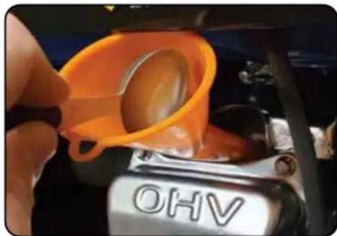
natural_image
Close-up of a hand pouring orange liquid into a car engine compartment with 'OHV' branding (no readable text beyond label)7. Add oil to cylinder
Add 2 tablespoons of 10W-30 motor oil directly into the spark plug hole, and pull the recoil to lubricate cylinder. After lubricating cylinder reinstall the spark plug.
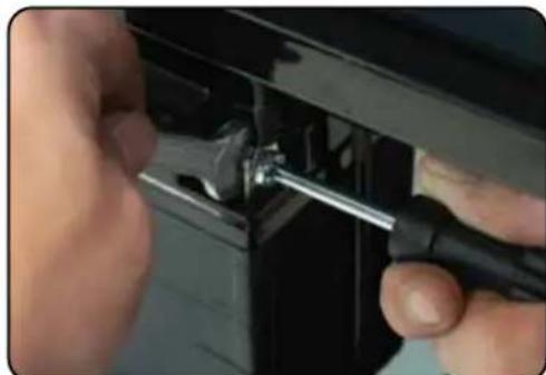
natural_image
Close-up of hands using a screwdriver to adjust or install a black plastic component (no visible text or symbols)8. Remove battery and charge
Remove the generator battery and place it on a 12V battery tender indoors.
SPECIFICATIONS
| Model Number XP12000E | |
| AC Rated Wattage 9,500 W | |
| AC Surge Wattage 12,000 W | |
| AC Rated Voltage 120/240V | |
| Dimensions 30"L x 30"W x 26"H | |
| Weight 217 lbs | |
| Recommended Oil 10W-30 | |
| Engine Displacement 457 cc | |
| Gasoline Capacity 8.3 gal | |
| Oil Capacity 40.5 fl. oz. (1.2 L) | |
| Bore 92 mm | |
| Stroke 69 mm | |
| Engine Speed 3600 rpm | |
| Oil Cooling Type Splash | |
| Bearing Type Stainless steel ball bearing | |
| Cylinder Sleeve Cast iron sleeve | |
| Fuel Delivery System Carburetor | |
| Valve Type OHV | |
| Engine Type | 4-Stroke |
| Engine Cooling Type Forced air | |
| Run Time @ 50% Load 8 hr. | |
| Starting Type Electric/ Recoil | |
| Noise Level | <74 dB |
| Neutral System | Floating |
| AC Rated Frequency | 60 Hz |
| AC Phase | Single |
| Winding Material | 100% copper windings |
TROUBLESHOOTING
This section of the manual is to help you troubleshoot problems with your generator.
TROUBLESHOOTING
| Problem Description | Solution | |
| The engine will not start | Engine switch is “Off” Set engine switch to “On” | |
| Fuel valve is “Closed” Turn the fuel valve to “Open” | ||
| Choke is open Close the choke | ||
| The engine is out of fuel Add fuel | ||
| Fuel is old or contaminated Change fuel | ||
| Spark plug is dirty Clean spark plug | ||
| Spark plug is broken Replace spark plug | ||
| The generator is not level | Move the generator to a level surface | |
| Oil is low Add/change the oil | ||
| Engine runs, but there is no electrical output | The circuit breaker is “Off” Turn “On” circuit breaker | |
| Wiring connection is bad Replace extension cord(s) | ||
| Device connected to generator is malfunctioning | Disconnect malfunctioning device | |
| The generator runs but does not support all electrical devices connected | Generator is overloaded | Disconnect 1 or more items to reduce the load |
| Device connected to the generator is bad | Disconnect malfunctioning device | |
| The air filter is dirty Clean/ replace the air filter | ||
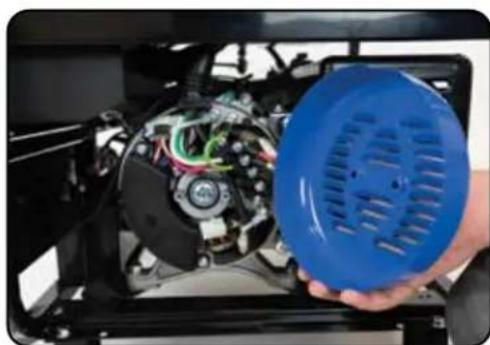
Changing/Inspecting the Carbon Brushes
natural_image
Close-up of a hand holding a blue circular device with visible wiring and components, no text or symbols present.The carbon brushes in conjunction with the AVR regulates power from the generator. The carbon brushes are wearable parts and should be inspected every 250 running hours.
natural_image
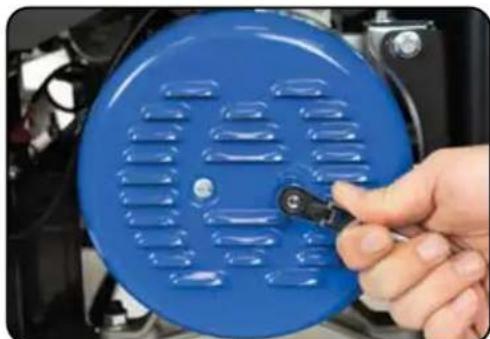
Close-up of a hand holding a blue circular mechanical component with ventilation slots (no visible text or symbols)1. Remove generator cover
Remove the 2 bolts of the generator cover then pull the cover off the generator.
natural_image
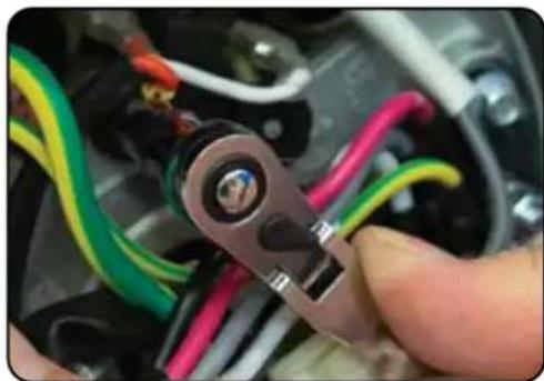
Close-up of a hand holding a handheld electrical switch with multicolored wires (no visible text or symbols)2. Remove bolt from brush
Remove the bolt holding the carbon brush.
natural_image
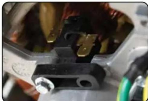
Close-up of mechanical components with no visible text or symbols3. Disconnect AVR wires
Remove the two wires from the AVR on the carbon brush.
■ TROUBLESHOOTING (CONTINUED)
Changing/Inspecting the Carbon Brushes (Cont.)
natural_image
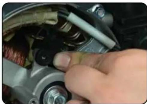
Close-up of a hand adjusting a car brake caliper component (no visible text or symbols)4. Install new brush
Install new carbon brush with bolt.
natural_image
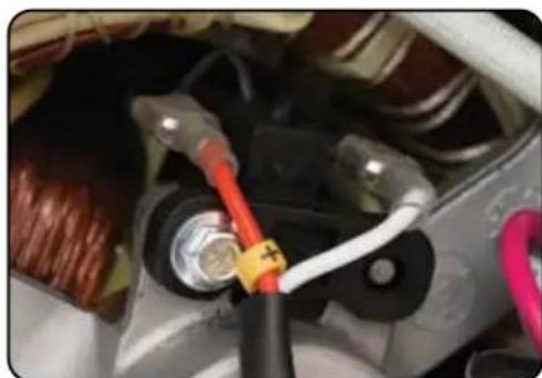
Close-up of a car's electrical connector with red and white wires, no visible text or symbols5. Connect AVR wires
Insert and connect the 2 wires from the AVR, be sure to connect + and - correctly.
natural_image
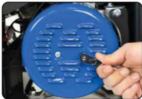
Close-up of a hand holding a blue circular device with a black clip, showing internal components (no text or symbols visible)6. Replace generator cover
Replace the back cover of the generator and secure it with the 2 bolts.
Changing/Inspecting the AVR

natural_image
Close-up of a hand holding a blue plastic fan inspecting an electronic device with visible wiring and components (no text or symbols)The carbon brushes in conjunction with the AVR regulates power from the generator. If the generator is overheated or overloaded, the AVR may be damaged and require replacement.
natural_image
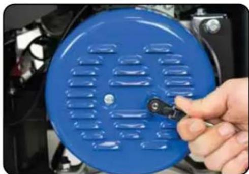
Close-up of a hand holding a blue circular component with ventilation grilles, next to a black handle (no visible text or symbols)1. Remove generator cover
Remove the 2 bolts of the generator cover then pull the cover off the generator.
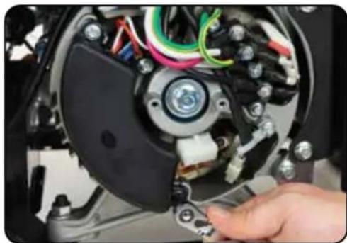
natural_image
Close-up of a hand adjusting a mechanical device with visible wiring and components (no text or symbols)2. Remove AVR bolts
Remove the 2 bolts holding the AVR.
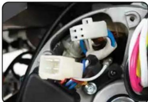
natural_image
Close-up of an automotive electronic component with white plastic connector and wiring (no visible text or symbols)3. Disconnect AVR wire clip
Disconnect the wire clip.
■ TROUBLESHOOTING (CONTINUED)
Changing/Inspecting the AVR (Continued)
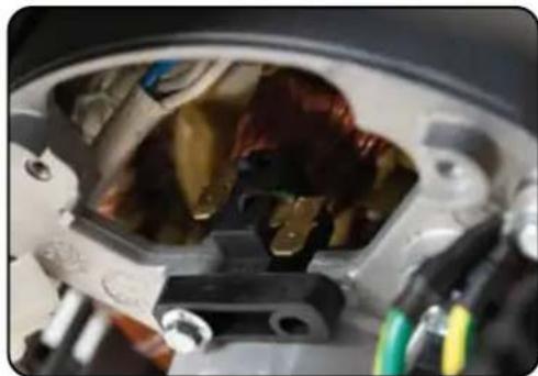
natural_image
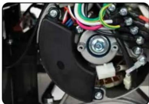
Close-up of a mechanical component with visible internal parts and mounting holes (no text or symbols)4. Disconnect wires from brush
Remove the 2 wires from the AVR on the carbon brush.
natural_image
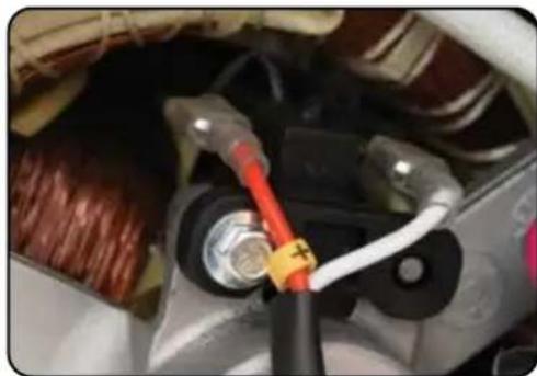
Close-up of an automotive electrical component with visible wiring and a central hub (no text or symbols)5. Install new AVR
Install the new AVR with the 2 bolts.
natural_image
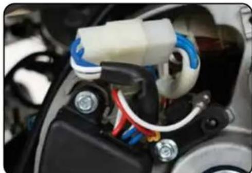
Close-up of a car engine component with red and white wires connected to a black connector (no visible text or symbols)6. Reconnect wires to brush
Insert and connect the 2 wires from the AVR, be sure to connect + and - correctly.
natural_image
Close-up of a mechanical component with wiring and connectors (no visible text or symbols)7. Reconnect the AVR wire clip
Reconnect the wire clip.
natural_image
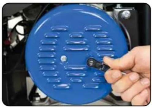
Close-up of a hand holding a blue circular device with ventilation grilles, mounted on a black engine (no visible text or symbols)8. Replace generator cover
Replace the back cover of the generator and secure it with the 2 bolts.
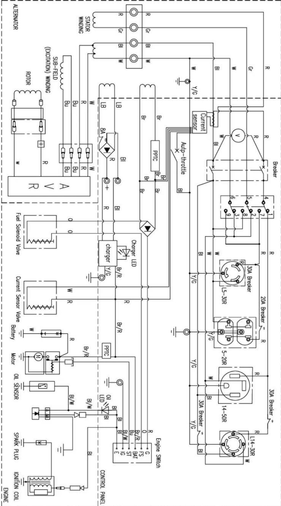
WRING DACRAM OF 120/240V GENERATOR SET
| Bl | Black | Br | Brown | Y/G | Yellow/Green |
| 0 | Orange | Br/R | Brown/Red | Bl/W | Black/White |
| Bu | Blue | LB | Light Blue | G | Green |
| Gr | Grey | Bl | Black | ||
| R | Red | W | White |
| 1G | E | BAT | ST | FS | G | |
Engine Switch Connecting
flowchart
graph TD
    subgraph Powertrain
        direction TB
        A["Engine"] --> B["Control Panel"]
        B --> C["Engine Switch"]
        C --> D["Engine"]
        D --> E["Engine"]
        E --> F["Motor"]
        F --> G["Oil Sensor"]
        G --> H["Spark Plug"]
        H --> I["Incension Coil"]
        J["Motor"] --> K["Oil Sensor"]
        K --> L["Spark Plug"]
        L --> M["Incension Coil"]
        N["Engine"] --> O["Power"]
        O --> P["Control Panel"]
        P --> Q["Engine"]
        Q --> R["Engine"]
        R --> S["Motor"]
        S --> T["Oil Sensor"]
        T --> U["Spark Plug"]
        U --> V["Incension Coil"]
        W["Engine"] --> X["Power"]
        X --> Y["Control Panel"]
        Y --> Z["Engine"]
        Z --> AA["Engine"]
        AA --> AB["Motor"]
        AB --> AC["Oil Sensor"]
        AC --> AD["Spark Plug"]
        AD --> AE["Incension Coil"]
        AF["Engine"] --> AG["Power"]
        AG --> AH["Control Panel"]
        AH --> AI["Engine"]
        AI --> AJ["Engine"]
        AJ --> AK["Motor"]
        AK --> AL["Oil Sensor"]
        AL --> AM["Spark Plug"]
        AM --> AN["Incension Coil"]
        AO["Engine"] --> AP["Power"]
        AP --> AQ["Control Panel"]
        AQ --> AR["Engine"]
        AR --> AS["Engine"]
        AS --> AT["Motor"]
        AT --> AU["Oil Sensor"]
        AU --> AV["Spark Plug"]
        AV --> AW["Incension Coil"]
        AX["Engine"] --> AY["Power"]
        AY --> AZ["Control Panel"]
        BA["Engine"] --> BB["Engine"]
        BB --> BC["Engine"]
        BC --> BD["Motor"]
        BD --> BE["Oil Sensor"]
        BE --> BF["Spark Plug"]
        BG["Engine"] --> BH["Power"]
        BH --> BI["Control Panel"]
        BI --> BJ["Engine"]
        BJ --> BK["Engine"]
        BK --> BL["Motor"]
        BL --> BM["Oil Sensor"]
        BM --> BN["Spark Plug"]
        BO["Engine"] --> BP["Power"]
        BP --> BQ["Control Panel"]
        BR["Engine"] --> BS["Engine"]
        BS --> BT["Engine"]
        BT --> BU["Motor"]
        BU --> BV["Oil Sensor"]
        BV --> BW["Spark Plug"]
        BX["Engine"] --> BY["Power"]
        BY --> BZ["Control Panel"]
        CA["Engine"] --> CB["Engine"]
        CB --> CC["Engine"]
Duro Max
3-year Warranty
All DuroMax Power Equipment warrant the original purchasers to a 3-year Parts Warranty (Residential Use ONLY: Unusually heavy or commercial use is covered for a period of 1-year) in the event of failure due to defects in electrical or mechanical components. Freight on any items submitted for replacement or repair under the Warranty is the responsibility of the equipment owner. This warranty is non-transferable and only valid to the original purchaser.
Warranty Exclusions
The DuroMax Power Equipment warranty does not cover repairs or returns when the fault is: Normal Wear and Tear, Installation Use or Maintenance Services, Cosmetic defects, Accessories, Failures due to acts of God or Natural Disasters, or problems related to/from aftermarket or non-OEM parts.
Warranty Limitations
DuroMax Power Equipment does not claim or hold any obligation to loss of time, freight charges, use of the product, or any incidental damages from the use of this product. THIS WARRANTY IS IN LIEU OF ALL OTHER WARRANTIES, EXPRESSED OR IMPLIED.

YOUR WARRANTY RIGHTS AND OBLIGATIONS
The United States Environmental Protection Agency and DuroMax Power Equipment, are pleased to explain the emission control system warranty on your 2023/2024 model year small off-road engine/equipment. In the United States, new small off-road engine/equipments must be designed, built and equipped to meet stringent anti smog standards. DuroMax must warrant the emission control system on your small off-road engine/equipment for the periods of time listed below provided there has been no abuse, neglect or improper maintenance of your small off-road engine/equipment.
Where a warrantable condition exists, DuroMax will repair your small off-road engine/equipment at no cost to you including diagnosis, parts and labor.
MANUFACTURER'S WARRANTY COVERAGE:
This emissions control system is warranted for two years. If any emission-related part on your small off-road engine/equipment is defective, the part will be repaired or replaced by DuroMax.
OWNER'S WARRANTY RESPONSIBILITIES:
As the small off-road engine/equipment owner, you are responsible for the performance of the required maintenance listed in your owner's manual. DuroMax recommends that you retain all receipts covering maintenance on your small off-road engine/equipment, but DuroMax cannot deny warranty solely for the lack of receipts or for your failure to ensure the performance of all scheduled maintenance.
As the small off-road engine/equipment owner, you should however be aware that DuroMax may deny you warranty coverage if your small off-road engine/equipment or a part has failed due to abuse, neglect, improper maintenance or unapproved modifications.
If you have any questions regarding your warranty rights and responsibilities, you should contact DuroMax at 844-387-6629 or support@duromaxpower.com.
DEFECTS WARRANTY REQUIREMENTS:
(a) The warranty period begins on the date the engine/equipment is delivered to an ultimate purchaser.
(b) General Emissions Warranty Coverage. DuroMax warrants to the ultimate purchaser and each subsequent owner that the engine/equipment is:
(1) Designed, built, and equipped so as to conform with all applicable regulations adopted by the Environmental Protection Agency.
WARRANTY (CONTINUED)
(2) Free from defects in materials and workmanship that causes the failure of a warranted part for a period of two years.
(c) Warranty Parts for Exhaust Emission.
(1) Fuel System
(2) Air Induction System
(3) Ignition System
The following parts are also considered emission related components for exhaust emissions, if applicable
(1) Exhaust Gas Recirculation (EGR) System
(2) After treatment devices.
(3) Crankcase ventilation valves.
(4) Sensors.
(5) Electronic control units.
(d) Warranty Parts for Evaporative Emission include fuel tank, fuel cap, fuel line and fittings, carbon canister, vapor hoses. They may also include, if applicable, liquid/vapor separator, clamps, pressure relief valves, etc.
DuroMax will furnish with each new engine/equipment written instructions for the maintenance and use of the engine/equipment by the owner.
CUSTOMER SERVICE
Duromax Power Equipment is committed to ensuring that our products perform when they need to. Our generators are your lifeline in the event of an emergency. Should you have any problems, please contact our customer service department:
DUROMAX POWER EQUIPMENT 5800 Ontario Mills Parkway Ontario, CA 91764
Customer Service: 844-DUROMAX Customer Service Hours: 8-5 pm PST Mon-Fri
Website: www.duromaxpower.com Email: customerservice@duromaxpower.com

natural_image
Woman in white work uniform and headset smiling while using a laptop (no visible text or symbols)
5800 Ontario Mills Parkway
Ontario, CA 91764
United States
844-DUROMAX
- CONTENTS
- Introduction
- Generator Components
- Generator Setup
- Starting the Generator
- Using the Generator
- 6.
- Stopping the Generator
- 7.
- Maintenance and Care
- 8.
- Troubleshooting
- 9.
- 10.
- Duro Max
- THE DUROMAX WAY
- POWERING EVERYONE... ANYWHERE!
- INTRODUCTION
- STOP
- Notice Regarding Emissions
- GENERAL SAFETY PROCEDURES
- SAFETY ALERT SYMBOL
- Please familiarize yourself with the following safety symbols and words:
- GENERAL SAFETY PROCEDURES (CONTINUED)
- WARNING
- DANGER
- CARBON MONOXIDE SAFETY
- Carbon Monoxide
- CO ALERT
- Description
- CO Detected
- Maintenance Required
- ALWAYS READ THE OWNER'S MANUAL FIRST
- KNOW THE SYMPTOMS
- UNIT AND PURCHASE INFORMATION
- Serial Number
- Serial number format
- STAPLE RECEIPT HERE
- GENERATOR COMPONENTS
- ■ PACKAGE CONTENTS
- GENERATOR SETUP
- Step 1 - Remove Shipping Braces
- Unpack
- Remove braces
- ■ GENERATOR SETUP (CONTINUED)
- Step 2 - Wheel Kit Installation (Optional)
- Install support legs
- Install wheel axles
- Install inside wheel washers
- Install wheels
- Install outside wheel washers
- Install cotter pins
- Install handles
- Flip over assembled
- Step 3 - Connect the Battery
- Remove the battery cover
- Locate the negative cable
- Connect the negative cable
- Reinstall the battery plate
- Step 4 - Adding Oil
- Engine oil recommended: SAE 10W-30.
- Add oil
- GENERATOR SETUP (CONTINUED)
- Step 5 - Adding Gasoline
- Add gasoline
- IMPORTANT:
- Step 6 - Grounding the Generator
- Attach grounding wire
- High Altitude Operation
- STARTING THE GENERATOR
- BEFORE YOU START YOUR GENERATOR
- Step 1 - Check the Oil
- Check the oil
- Step 2 - Check the Gas Level
- Check fuel level
- WARNING: Gasoline and gasoline fumes are highly flammable.
- ■ STARTING THE GENERATOR
- Shut breaker OFF
- Turn gas valve ON
- Close choke
- Turn idle control OFF
- Turn engine switch to START
- Open choke
- Turn breaker ON/Connect
- ■ STARTING THE GENERATOR (CONTINUED)
- Starting the Generator Using Recoil Start
- Turn engine switch to ON
- Turn idle control OFF
- Pull the recoil start
- Open choke
- Turn breaker ON/Connect
- USING THE GENERATOR
- AC Usage
- Connecting the Generator to a Home
- Interlock kit
- Transfer switch
- Extension cords
- ■ USING THE GENERATOR (CONTINUED)
- Connecting a Load to the Generator
- Plug in devices
- Turn breaker ON
- Turn on connected devices
- Choosing the Right Power Cord
- ■ USING THE GENERATOR (CONTINUED)USING TH
- DC Usage
- Connect the battery
- Connect positive receptacle
- Start generator
- Connect negative receptacle
- Disconnecting battery
- Voltage Selector Switch
- Idle Control Usage
- Idle control
- ■ STOPPING THE GENERATOR
- Shutting Down the Generator
- Turn the main breaker OFF
- Run the generator
- Turn the key switch OFF
- Turn fuel valve OFF
- Maintenance Schedule
- Break-In Period
- Maintenance Log
- ■ MAINTENANCE AND CARE (CONTINUED)
- Checking the Oil
- Changing the Oil
- Remove drain plug
- Drain oil
- Replace drain plug
- Cleaning the Air Filter
- Remove the filter cover
- Remove filter
- Clean out filter casing
- Wash cleaner element
- Dry cleaner element
- Add engine oil to elements
- Replace elements in casing
- Spark Plug Maintenance
- Remove spark plug cap
- Remove spark plug
- Inspect spark plug
- Measure plug gap
- Clean and re-gap
- Install spark plug
- Replace spark plug cap
- Emptying the Gas Tank
- Shut fuel valve OFF
- Remove fuel filter cup
- Empty fuel filter cup
- Drain gas from the generator
- Shut fuel valve OFF
- Replace fuel filter cup
- Store emptied gas
- Cleaning the Fuel Filter Cup
- Clean filter cup
- Replace fuel filter cup
- Transporting the Generator
- Empty the gas tank
- Disconnect the spark plug
- Storing the Generator for Use Within 30 Days
- Turn breaker OFF and run
- Shut fuel valve OFF and run dry
- Add fuel stabilizer and store
- Storing the Generator for Longer Than 30 Days
- Empty the gas tank
- Drain the carburetor
- Remove spark plug
- Add oil to cylinder
- Remove battery and charge
- SPECIFICATIONS
- Changing/Inspecting the Carbon Brushes
- Remove generator cover
- Remove bolt from brush
- Disconnect AVR wires
- ■ TROUBLESHOOTING (CONTINUED)
- Changing/Inspecting the Carbon Brushes (Cont.)
- Install new brush
- Connect AVR wires
- Replace generator cover
- Changing/Inspecting the AVR
- Remove AVR bolts
- Disconnect AVR wire clip
- Changing/Inspecting the AVR (Continued)
- Disconnect wires from brush
- Install new AVR
- Reconnect wires to brush
- Reconnect the AVR wire clip
- Replace generator cover
- 3-year Warranty
- Warranty Exclusions
- Warranty Limitations
- YOUR WARRANTY RIGHTS AND OBLIGATIONS
- MANUFACTURER'S WARRANTY COVERAGE:
- OWNER'S WARRANTY RESPONSIBILITIES:
- DEFECTS WARRANTY REQUIREMENTS:
- WARRANTY (CONTINUED)
- CUSTOMER SERVICE
- DUROMAX POWER EQUIPMENT 5800 Ontario Mills Parkway Ontario, CA 91764
Brand : DuroMax
Model : XP12000E
Category : Generator