
EMR-16 - Digital recorder Elmo - Free user manual and instructions
Find the device manual for free EMR-16 Elmo in PDF.


| Product Type | Digital Video Recorder (DVR) |
| Model | EMR-16 |
| Brand | Elmo |
| Recording Medium | Hard Disk Drive (up to 4 units) |
| Video Input | 16 channels (BNC connectors) |
| Video Compression | Motion JPEG (720 x 240 pixels) |
| Audio Recording | Yes, simultaneous with video |
| Recording Modes | Manual, Continuous Timer, Alarm, Motion Detection |
| Playback Features | Forward/backward, variable speed, frame-by-frame, search by date/time/event |
| Duplex Operation | Record and playback simultaneously |
| PTZ Camera Control | RS-485, protocols: Elmo, Pelco D, Panasonic |
| Network Interface | Ethernet (RJ-45), Web server for remote live view, playback, setup, download |
| Alarm Inputs/Outputs | 16 alarm inputs terminal block, TTL/normally open; alarm output DC24V max 20mA |
| USB Ports | 1 for archiving (USB 2.0), 1 for mouse |
| DVD Drive | Optional internal DVD-R/RW drive |
| Monitor Outputs | 2 BNC outputs (Monitor 1 and Monitor 2) |
| Power Supply | 120 V AC, 60 Hz |
| Dimensions (W x H x D) | 420.5 mm x 88 mm x 368 mm |
| Operating Temperature | 5°C to 40°C (41°F to 104°F) |
| Humidity | 30% to 80% (non-condensing) |
Frequently Asked Questions - EMR-16 Elmo
User questions about EMR-16 Elmo
0 question about this device. Answer the ones you know or ask your own.
Ask a new question about this device
Download the instructions for your Digital recorder in PDF format for free! Find your manual EMR-16 - Elmo and take your electronic device back in hand. On this page are published all the documents necessary for the use of your device. EMR-16 by Elmo.
USER MANUAL EMR-16 Elmo
Recording Medium (Hard Disk) and Radiating Fan....6
Motion Detect (Movement Detection) Function 6
System Structuring 6
Ethernet Terminal 6
When Malfunction Occurs ....6
Handling of Recorded Data 6
Features....7
Accessories....8
Names and Functions....9
Front Face....9
Back Face 11
Connection....12
Standard Connection Example....12
Example of Connection with VP Power Unit (VC90P, etc)....13
Example of Connection with Alarm Devices....14
Example of Connection with External Control Equipment....15
Example of Connection with External Storage Media 16
Example of Connection of PTZ Camera 16
Example of Connection with Expansion Hard Disk Unit....17
How To Use....18
Starting Up 18
Turning Off 18
Viewing Live Feeds 19
Screen Display While Showing Live Feeds....19
Switching Cameras 20
Display in Split Screen....20
Automatic Sequence Display 22
PTZ Camera Control 22
2X Digital Zoom Display 24
Viewing Live Feeds from Monitor 2....24
Recording....25
Screen Display During Recording 25
Manual Recording 26
Using Automatic Recording Mode 26
Playback....27
Screen Display During Playback 27
Playback/Stop Playback....28
Changing Playback Speed 29
Playback Frame by Frame 29
Playback at Fast Speed....30
Display in Split Screen....30
How to Use LAYOUT Function....31
Finishing LAYOUT Function 33
Search and Playback Recorded Video 34
Copy Function....38
How to Copy 38
Stop Copying....41
Image File Format Copied to USB Media 41
Image File Format Copied to DVD 41
WEB Server Function 42
Functions 42
Physical Connection Configuration....42
Operation Environment 42
Login/Logout 43
LIVE FEED 45
PLAYBACK 46
MENU 49
E-Mail Function....51
How To Set Up....52
How to Start and Finish Menu Mode....52
Operation of Menu Screen....54
List of Menu Functions....55
Main menu screen 59
Recording Setup 60
Recording Conditions Setup 61
Recording Schedule Setup 63
Concurrent Recording Camera Setup....65
Holiday Setup....66
Motion Setup 67
Screen Display Setup 69
OSD Display Setup 70
Monitor Output Setup 72
Automatic Sequence Setup....73
Camera Name Setup 74
Network Setup 75
E-mail Setup 76
Sending Condition Setup 78
System Setup....79
Control Camera Setup Screen 80
User Setup 81
Log Display 83
Recording Log 83
Error Log 84
Startup Log 85
User Log....86
Equipment Maintenance 88
Writing Method 89
How to Format Hard Disks 89
Operation Under Error Status 91
Hard Disk Error 91
Video Loss ......Error! Bookmark not defined.
Output under Error Status 92
Troubleshooting 93
Warranty and Services 94
Warranty 94
When requesting repair during warranty period 94
Repair after expiration of warranty period 94
Inquiry 94
Repair Parts 94
Specifications....95
Appendix....99
Recording Time Table 99
JPEG Display Software: "Resize Viewer" 113
Specifications 113
Operation Requirements 113
Screen Display and Operation 114
File Display Order....115
External Dimensions 116
Introduction
Thank you very much for your purchasing ELMO Digital Video Recorder. Before use, please read this Instruction Manual carefully so that you may be able to use your newly acquired digital video recorder properly.
After reading, be sure to keep it handy for reference.

The lightning flash with arrowhead symbol, within an equilateral triangle, is intended to alert the user to the presence of uninsulated "dangerous voltage" within the product's enclosure that may be of sufficient magnitude to constitute a risk of electric shock to persons.
The exclamation point within an equilateral triangle is intended to alert the user to the presence of important operating and maintenance (servicing) instructions in the literature accompanying the appliance.
CAUTION
Do not use any power supply other than specified.
WARNING
TO REDUCE THE RISK OF FIRE OR ELECTRIC SHOCK, DO NOT EXPOSE THIS APPLIANCE TO RAIN OR MOISTURE.
This class A digital apparatus meets all requirements of the Canadian Interference-Causing Equipment Regulations.
This equipment has been tested and found to comply with the limits for Class A digital device, pursuant to Part 15 of the FCC Rules. These limits are designed to provide reasonable protection against harmful interference when the equipment is operated in a commercial environment.
This equipment generates, uses, and can radiate radio frequency energy and, if not installed and used in accordance with the instruction manual, may cause harmful interference to radio communications.
Operation of this equipment in a residential area is likely to cause harmful interference in which case the user will be required to correct the interference at his own expense.
USER-INSTALLER CAUTION: Your authority to operate this FCC verified equipment could be voided if you make changes or modifications not expressly approved by the party responsible for compliance to Part of the FCC Rules.
IMPORTANT SAFETY INSTRUCTIONS
- Read these instructions.
- Keep these instructions.
- Heed all warnings.
- Follow all instructions.
- Do not use this apparatus near water.
- Clean only with dry cloth.
- Do not block any ventilation openings. Install in accordance with the manufacturer's instructions.
- Do not install near any heat sources such as radiators, heat registers, stoves or other apparatus (including amplifiers) that produce heat.
- Do not defeat the safety purpose of the polarized or grounding-type plug.
A polarized plug has two blades with one wider than the other. A grounding type plug has two blades and a third grounding prong. The wide blade or the third prong are provided for your safety. If the provided plug does not fit into your outlet, consult an electrician for replacement of the obsolete outlet.
-
Protect the power cord from being walked on or pinched particularly at plugs, convenience receptacles, and the point where they exit from the apparatus.
-
Only use attachments/accessories specified by the manufacturer.
-
Use only with the cart, stand, tripod, bracket, or table specified by the manufacturer, or sold with the apparatus. When a cart is used, use caution when moving the cart/apparatus combination to avoid injury from tip-over.
-
Unplug this apparatus during lightning storms or when unused for long periods of time.
-
Refer all servicing to qualified service personnel. Servicing is required when the apparatus has been damaged in any way, such as power-supply cord or plug is damaged, liquid has been spilled or objects have fallen into the apparatus, the apparatus has been exposed to rain or moisture, does not operate normally, or has been dropped.
-
The apparatus is not waterproofs, to prevent fire or shock hazard, do not expose this appliance to rain or moisture and do not put any water source near this apparatus, such as vase, flower pot, cosmetics container and medicine bottle etc.
-
Grounding or Polarization - This product may be equipped with either a polarized 2-wire AC line plug (a plug having one blade wider than the other) or a 3-wire grounding type plug, a plug having a third (grounding) pin. The 2-wire polarized plug will fit into the power outlet only one way, This is a safety feature. If you are unable to insert the plug fully into the outlet, try reversing the plug. If the plug still fails to fit, contact your electrician to replace your obsolete outlet. Do not defeat the safety purpose of the polarized plug. The 3-wire grounding type plug will fit into a grounding type power outlet. This is a safety feature. If you are unable to insert the plug into the outlet, contact your electrician to replace your obsolete outlet. Do not defeat the safety purpose of the grounding type plug.
-
Lightning - For added protection for this product during a lightning storm, or when it is left unattended and unused for long periods of time, unplug it from the wall outlet and disconnect the antenna or cable system. This will prevent damage to the product due to lightning and power-line surges.

PRECAUTIONS
- Refer all work related to the installation of these products to qualified service personnel or system installers.
- Do not operate the appliances beyond their specified temperature, humidity, or power source ratings.
Use the appliance at temperatures within +5 °C - +40 °C (41 °F - 104 °F) and humidity below 80 %.
The input power source for this appliance is 120 V AC 60 Hz.
Performance and lifetime of hard disk drives are easily affected by heat (used at high temperature) characteristically. It is recommended to use this appliance at temperatures within +20 °C - +30 °C (68 °F - 86 °F).
- Handle the appliance with care.
Do not strike or shake, as this may damage the appliance.
- Do not strike or give a strong shock to the unit.
It may cause damage or allow water to enter the unit.
- Cooling Fan
Turn off the power when cleaning the unit. Otherwise it may cause injuries.
- Cleaning
Turn off the power when cleaning the unit. Otherwise it may cause injuries.
Do not use strong or abrasive detergents when cleaning the appliance body.
Use a dry cloth to clean the appliance when it is dirty.
When the dirt is hard to remove, use a mild detergent and wipe gently.
- Indication label
Refer to the indication labels placed on the back of the unit as to the indications of equipment classification and power source, etc.
- Built-in hard disk drives
Hard disk drives are vulnerable to vibration. Handle them with care.
It is possible to damage them if they are moved while their motors are still running. Do not move them just after turning their power on or off (for around 30 seconds).
When hard disk drive trouble occurs, replace it immediately. Consult your dealer for servicing.
When replacing the hard disk drivers, take notice of the following.
- Place the unit horizontally an a level surface. Do not place the unit in an upright position.
When stacking multiple units, clear a space of more than 5 cm from both sides, the top, the bottom and the rear of the units. - Avoid placing receptacles that contain liquids such as water near the unit.
- If liquid spills onto the unit, it may cause fire or an electric shock.
- Do not expose the unit to water or moisture, or try to operate it in wet areas.
-
Wait until the dew evaporates in any of the following cases;
-
The recorder is placed in an extremely humid place.
- The recorder is placed in a room where a heater has just been turned on.
- The recorder is moved from an air-conditioned room to a humid and high-temperature room.
- We recommend that you make a note of your settings and save them. This will help when you are required to change the system configuration, or when unexpected trouble or failure occurs.
- Distributing, copying, disassembling, reverse compiling, reverse engineering and also exporting in violation of export laws of the software provided with this product, is expressly prohibited.
WARNING
Handling the cord on this product or cords associated with accessories sold with this product, will expose you to lead, a chemical known to the State of California to cause birth defects or other reproductive harm.
Wash hands after handling.
Before Use
Below are the reminders you definitely need to know before using the equipment.
Installation
Use Environment
• Install the equipment in the environment at temperatures within 5 to 40° and humidity between 30 and 80% (where no due condensation)
- When changing the place of installation, be sure to turn off the main power and pull off the power plug from the outlet.
- Do not install at places exposed to dust, oily, smoke, steam, or direct sunlight. The equipment has a air cooling fan system, and therefore, be sure to allow a space over 10 cm from the wall. Dust can accumulate in the ventilating openings even in not dusty places. As use in such a condition can cause abnormal internal temperature rising, clean the ventilating openings after turning the main power off and disconnecting the power plug from the outlet. It is advisable to clean the ventilating openings about once a year.
- Do not install the equipment in strong electromagnetic fields or radio waves.
- Installing the equipment in close proximity to wireless devices such as radios or televisions can result in poor reception.
- Place the equipment at a level and stable place. Do not install the equipment sideways up.
- Hard disks are installed inside the equipment. Shocks or vibrations can cause damages or malfunctioning of the hard disks. Give due consideration to the installation environment.
Handling
- Hard disks are installed inside the equipment. Handle with due caution so as not to give shocks or vibrations regardless of operating or non-operating to avoid malfunctioning.
- Do not unplug the power cord during recording, playback or other operations.
Other Cautions
Recording Medium (Hard Disk) and Radiating Fan
- The hard disk and radiating fan installed inside the equipment are expendables.
- When replacing, consult the reseller of your purchase. (Service is chargeable even during the warranty)
- A reference life of the hard disk is about 3 years for replacement. (Be advised that this duration is simply a reference, and by no means guarantees its performance)
Motion Detect (Movement Detection) Function
- In order to use the motion detect function built into the equipment, conduct the required setup according to the target to be detected.
- When constructing a system for giving an alarm sound in connection with the motion detect function of the equipment, beware of malfunctioning. In order to avoid malfunctioning or non-functioning, consider the use of appropriate sensors in combination.
System Structuring
- When controlling the equipment through the Ethernet terminal in a certain monitoring system setup, malfunction of this equipment or external equipment due to the setup therein or the connection or combination status of devices can affect the entire monitoring system.
- When structuring a monitoring system using this equipment, be advised to thoroughly confirm in advance the operation after connecting or combining the equipment with other equipment.
Ethernet Terminal
- When considering network connection, be advised to consult the network administrators or engineers about setup or equipment requirements in advance.
- The network function of this equipment does not guarantee the connection with all other network devices.
When Malfunction Occurs
- In the event of malfunction, turn the main power off, disconnect the power cord from the outlet, and contact your reseller. Leave the repair work to the specialized repair staff.
Handling of Recorded Data
- Before conducting important recording, perform test recording to make sure of normal recording operation. In the case of setup for long recording mode by lowering the resolution, confirm that the video image quality necessary for recorded footage is secured.
- Be advised that no compensation is available for incidental damage caused by malfunction or defective condition of this equipment or other equipment during recording (such as no recording, no normal playback, loss or the recorded video or sound data, etc)
- This equipment is capable of digital recording video images. Care is needed when recording copyrighted footages.
- In case monitor cameras are set up for the purpose of recording videos with this equipment, the direction or location of cameras that are recording should take into consideration the protection of privacy or portrait rights.
- Video data recorded using this equipment can be regarded as the “personal information” stipulated in the “Private Information Protection Law.” Due caution is needed for handling such video data.
Features
■ High Quality Digital Video and Sound Recording
Compared to the conventional VTR using tape recording, digital recording onto a hard disk enables recording of higher quality video and sound data. Unlike tape recording, rewinding or cuing takes very little time..
The recording pixel size is 720 × 240 per video image. Highly recognized Motion-JPEG is adopted for the data compression method during video recording. A variety of settings are available depending on the purposes and total recording time by means of 4-level image quality setup and recording interval setup ranging from the shortest of 1/60 second to the longest of 1 seconds.
Sound can be recorded simultaneously for any video recording setups.
■ Maximum of 4 Units of Large Capacity Hard Disk Drives Can Be Mounted
Up to 4 large capacity hard disk drives can be mounted for recording video and sound.
Extended recording is possible by recording onto one hard disk at a time, or highly reliable mirror recording is viable by recording onto 2 hard disks at the same time.
■ Handling Input from 16 Cameras
16 input terminals for video signal are provided. The equipment is capable of receiving input from standard video cameras and recording. The video quality and recording intervals can be separately set up for each of the input cameras.
The video images from the input cameras can be displayed on the monitor according to the desired purposes such as split-screen display or automatic sequence.
The monitor output comes in 2 lines (Monitor 1 and Monitor 2). The monitor display can be operated separately for each output, capable of a wide variety of monitoring operations.
■ Simultaneous Operation of Recording, Playback and Live Display
Playback of recorded video is possible while recording continues. (Duplex operation)
Playback image and live image can be displayed singly on the monitor or in screen splits. In the screen split display mode, LAYOUT setup is also available wherein recording continues while playback image from the hard disk as well as live camera images are simultaneously displayed.
There is no need to stop recording, so important scenes can be continuously recorded while checking the recorded data.
■ 2 Types of Recording Modes
In addition to manual recording mode where recording is started by pushing the recording button, automatic recording mode is programmed in which timer setup, alarm input or motion (movements on the monitor) detection automatically starts recording operation according to the preprogrammed schedules for each monitor camera.
In the automatic recording mode, timer setup, alarm input, and motion detection can be set up in combination. This enables a flexible operation according to a variety of monitor requirements.
■ Motion Detect (Movement Detection) Function
Automatic recording can be programmed for a situation wherein movement is detected within a certain designated area of the recording range of an input camera.
■ Convenient Functions of Search and Playback
By specifying recording date and time or events of recording start (manual, alarm input, motion detection, etc), the desired recording video can be quickly searched.
Playback can be done at normal and high speed, as well as in reverse.
■ Capable of Remote Monitoring Via Network
Ethernet terminal is provided as standard equipment enabling connection with networks.
By accessing the Web server installed in the equipment via multi-purpose browser from other hosts on the same network, it is able to operate various functions such as distribution of live feeds from the cameras, search or playback of recorded video, remote control or setup of the equipment, etc.
When connecting our-recommended PTZ cameras, these are also remotely controlled (RS-485) from the browser screen.
Accessories
Below are the accessories of this equipment:
Power supply AC cable
Instruction manual
Cautionary statement
Names and Functions
Below are the names and functions of each control on this equipment:
Front Face

| No. | Name | Description |
| 1 | POWER Key | When pushing the POWER switch while recording, playback or live feed display, the screen display of Monitor 1, buzzer, and each indicator will be turned OFF.When pushing the POWER switch during recording, the recording operation is continued though the screen display is turned off. The screen is displayed when pushing the POWER switch again. |
| 2 | RECORDING Indicator | Indicates the recording statusIndicator ON: Recording in progressIndicator OFF: Other than recording |
| ALARM Indicator (Red) | Indicates whether alarm given or notIndicator ON: Malfunction of equipmentIndicator OFF: Operation normal | |
| HDD Indicator | Indicates the blank space of the hard diskGreen: Disk space is sufficient.Orange: Disk usage is approaching maximum.Red: Disk space is insufficient.* Indicates only whenof “Recording Setup” is set in “NO.” | |
| 3 | Camera Selection Key Key 1 ~ 16 | Selects the channel for full screen display of live feeds or playback video.The selection position can be set in the LAYOUT setting, and the position synchronizes with the 16-split screen. (When there is L2 at the default position whose default is L1, pushing 1 displays the L2 single screen.) |
| Functions as cursor keys while Operation / Setup Display is showing 3: Up、6: Left、8: Right、11: Down、7: Select124591012~16: Not able to use | ||
| 4 | UP Key Increase the setup value | |
| DOWN Key Decrease the setup value | ||
| SEARCH Key Used for search of recorded video data.Pushing this key shows Search screenWhen operation is possible, lamp on the key lights up. | ||
| Recording Key (●)/Recording Stop Key(■) | Starts or stops manual recording.Pushing Recording Key starts manual recording, and pushing it again stops the manual recording.Lamp on the key lights up while manual recording in progress. | |
| SEQ DISP Key | Automatically switches video images according to the setup.See “Automatic Sequence Setup” under “Screen Display Setup”(→P.73) for how to set up | |
| SCRN DIV Key | Displays the Screen Division Setup screen. (→P.20) | |
| MENU Key Displays the Operation / Setup Menu on the screen.The key lamp lights up when operation is possible. | ||
| CAM Key When pushing this key in the single screen mode, PTZ camera control menu is displayed. | ||
| MON 2 Key To be pushed when operating Monitor 2 output.Pushing again puts back to operation of Monitor 1 output.The key lamp lights up during operation of Monitor 2. | ||
| 5 | Jog DialShuttle Dial | Conducts jog or shuttle operation during playback or playback pause.See “Changing Playback Speed” (→P.29) and “Playback Frame by Frame” (→P.29). |
| 6 | SKIP Key ) | Skips to the beginning and start playback in playback video screen.Setup of playback video screen is in LAYOUT.(→P.31) |
| Playback/Pause Key(▶) | Plays back recorded video forward in playback video screen.Setup of playback video screen is in LAYOUT.(→P.31)Pauses the video during playback or backward playback.Each time you push this key, the operation changes from play to pause or from pause to play. | |
| Stop Key (■) | Stops the playback in playback video screen.Setup of playback video screen is in LAYOUT.(→P.31) | |
| BackwardPlayback/Pause Key(◀) | Plays back recorded video backward in playback video screen.Setup of playback video screen is in LAYOUT.(→P.31)Pauses the video during playback or backward playback.Each time you push this key, the operation changes from backward play to pause or from pause to backward play. | |
| Skip Key | Skips to the last recorded position and plays backward in playback video screen.Setup of playback video screen is in LAYOUT.(→P.31) | |
| 7 | USB Port(ARCHIVE) | Connects USB media. The recorded video data or setup status can be stored onto the connected USB media. |
| USB Port(MOUSE) | Connects USB Mouse. This equipment can be operated using the connected USB mouse. | |
| 8 | DVD Drive | DVD drive can be stored within. (Optional) |
Back Face
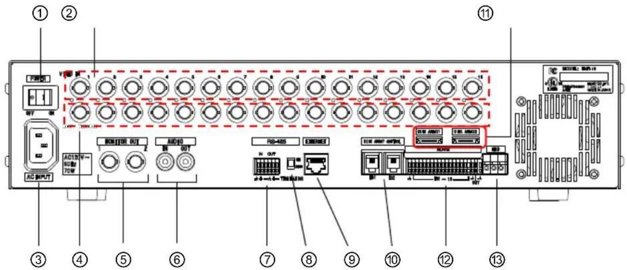
| No. | Names | Description |
| 1 | POWER Switch Turns the power of this equipment on and off.Pushing toward the right turns the power ON and toward the left turns OFF. | |
| 2 | VIDEO IN | Video input connectors for Channels 1 ~ 16. Connect the video output terminals from cameras, or other devices |
| 3 | AC Inlet Power in 120V | AC 60Hz is supplied here to. Connect the power cord to this inlet.Disconnecting the cord from this inlet stops all functions of the equipment. |
| 4 | LOOP THROUGH | Loop connectors for the video input of Channels 1 ~ 16. To be used for distribution of video signals to other equipment. |
| 5 | MONITOR OUT 1 MONITOR OUT 2 | Output for video signal to be connected with monitors.MONITOR 1: Capable of displaying live feeds, playback video images, and setup display screen.MONITOR 2: Only for displaying live feeds. |
| 6 | AUDIO IN AUDIO OUT | Input and output connectors for audio signals |
| 7 | RS-485 Terminal Block | 6P Terminal Block for RS-485 |
| 8 | RS-485 Termination Switch | To be set in ON in case no other equipment is connected after this equipment when connecting RS-485 |
| 9 | Ethernet Terminal | RJ-45 connector for Ethernet, capable of connecting with various networks |
| 10 | DISK ARRAY CONTROL | Terminal for HDD expansion unit (EMR-ESU) control (quadplex-pole quadplex-core), for connecting with the control cable attached to EMR-ESU |
| 11 | DISK ARRAY 1/2 c-SA | TA terminal for HDD expansion unit (EMR-ESU) connection, connecting with the c-SATA cable attached to EMR-ESU |
| 12 | ALARM Terminal Block | Terminal Block for input and output of alarm signals |
| 13 | GND Connects the grounding wire. | |
Connection
Below are the instructions on how to connect the equipment with other equipment:
Caution
- When connecting this equipment with other equipment, be sure to turn off the power of all equipment to be connected.
Standard Connection Example

flowchart
graph TD
    A["To Camera Input Terminal"] --> B["Control Equipment"]
    B --> C["Microphone"]
    C --> D["BNC-BNC Coaxial Cable"]
    D --> E["CCD Camera 1"]
    D --> F["CCD Camera 16"]
    A --> G["To Monitor Connector"]
    G --> H["To Video Input Terminal"]
    H --> I["Color Monitor TV 1"]
    H --> J["Color Monitor TV 16"]
    A --> K["To Monitor Connector"]
    K --> L["BNC-BNC Coaxial Cable"]
    L --> M["To Video Input Terminal"]
    M --> N["Color Monitor TV"]
    M --> O["To Sound Input Terminal"]
Example of Connection with VP Power Unit (VC90P, etc)

flowchart
graph TD
    A["VP Multiple Camera"] --> B["BNC-BNC Coaxial Cable"]
    C["16"] --> D["To Camera Input Terminal"]
    D --> E["VP Power Unit"]
    E --> F["To Sound Output Terminal"]
    F --> G["BNC-BNC Coaxial Cable"]
    G --> H["To Video Input Connector"]
    H --> I["Color Monitor TV"]
    I --> J["To Sound Input Terminal"]
    J --> K["BNC-BNC Coaxial Cable"]
    K --> L["To Video Input Terminal"]
    L --> M["To Sound Output Terminal"]
    M --> N["To Video Input Terminal"]
    N --> O["To Sound Input Terminal"]
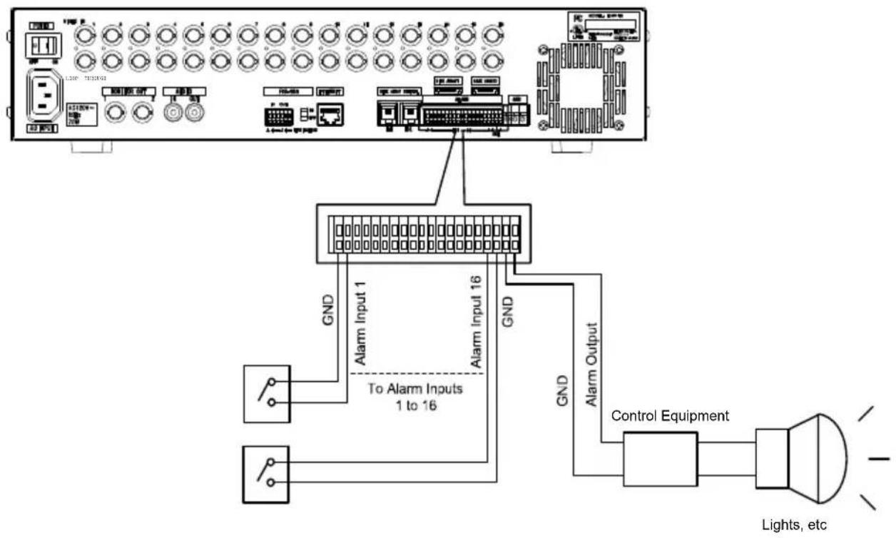
Example of Connection with Alarm Devices
flowchart
graph TD
    A["Alarm Input 1"] -->|GND| B["To Alarm Inputs 1 to 16"]
    C["Alarm Input 16"] -->|GND| B
    D["Control Equipment"] -->|GND| B
    B --> E["Lights, etc"]
■ Connection with Sensor
A sensor can be connected to the terminal block on the back as input from alarm signal. Use no-voltage, normally open output type
Terminal Specification
| Input / Output Terminal | Input / Output Terminal Circuit Signal Specification | |
| • Alarm input |  | TTL negative logic, or no-voltage, normally open outputPulse width; over 100ms |
| • Alarm output |  | Maximum of DC24V、Under 20mA |
Example of Connection with External Control Equipment
■ Mouse
Connect a mouse to the USB Port (MOUSE) on the front of the equipment.

■ Ethernet
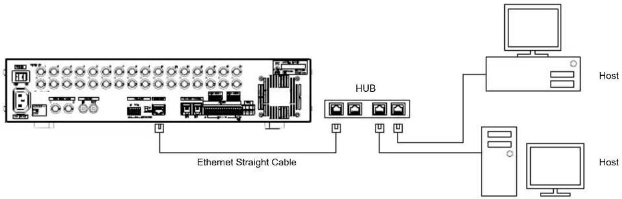
- When connecting via HUB:
flowchart
graph TD
    A["Router"] -->|Ethernet Straight Cable| B["HUB"]
    B --> C["Host"]
    B --> D["Host"]
    B --> E["Computer"]
Connect the Ethernet Terminal of this equipment with the HUB port. Use other than MDI Port of the HUB.
Use Ethernet straight cable (UTP Category 5) available for general use.
- When connecting directly with PC:
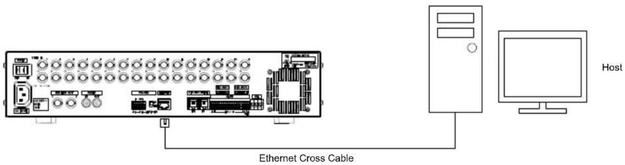
Connect the Ethernet Terminal of this equipment with that of the host.
Use Ethernet cross cable (UTP Category 5) available for general use.
Example of Connection with External Storage Media
USB
By connecting USB media to USB Port (ARCHIVE) on the equipment front, video or equipment setup data can be stored onto it.
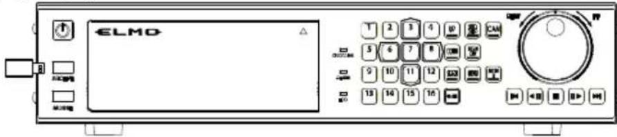
Caution
- USB media to be used must be USB-compliant USB mass storage compatible, with power consumption under 500mA. (However, it does not guarantee connection with all equipment) For more information, contact the shop staff.
- The media to be used with this equipment needs to be formatted in FAT12/FAT16. Format the media with PC, etc. before using it with this equipment. As for the formatting method, consult the instruction manuals of the PC or OS being used.
Example of Connection of PTZ Camera
■ PTZ (Pan, Tilt, Zoom) Camera
Our recommended PTZ cameras can be connected and controlled via RS-485.
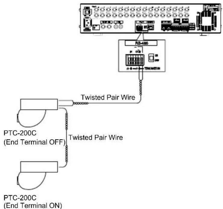
NOTE: Supported PTZ Protocols are: ELMO, PELCO D, Panasonic
Caution
- When connecting with this equipment using the network function, the RS-485ID in the camera side needs to be set according to the camera number. When operating from using the network function, the camera's ID should be set by the control camera ID.
- (e.g. For connection with Camera 3, set the RS-485ID address on the camera side to the same set number for Camera 3.)
Example of Connection with Expansion Hard Disk Unit
See Instruction Manual of the expansion hard disk unit EMR-ESU for more details.
The display indication of the hard disk information on this equipment is as follows:
| BUS | Indication | No. | Master / Slave |
| Installed Primary (IDE0) HDD-A | Master | ||
| Slave | |||
| Installed Secondary (IDE1) HDD-B | Master | ||
| Slave | |||
| Expansion HDD Unit 1 | HDD-C | 0 | Master |
| 1 | Master | ||
| 2 | Master | ||
| 3 | Master | ||
| HDD-D | 0 | Master | |
| 1 | Master | ||
| 2 | Master | ||
| 3 | Master | ||
| Expansion HDD Unit 2 | HDD-E | 0 | Master |
| 1 | Master | ||
| 2 | Master | ||
| 3 | Master | ||
| HDD-F | 0 | Master | |
| 1 | Master | ||
| 2 | Master | ||
| 3 | Master |
How To Use
Below are basic explanations for using this equipment:
Starting Up
-
Connect the provided power cable and each device appropriately.
-
Turn the POWER Switch on the back face "ON."
-
The screen shows the System Check display, and the hard disk Connection Check begins. During the Connection Check, the "POWER" key flickers.

flowchart
graph LR
    A["EMR-16"] -->|Ver 1.00\n0009| B["SYSTEM INITIALIZING."]
    B --> C["......"]
After the System Check finishes, the "POWER" key changes to lighting mode, and a live feed is shown. (In case of factory default setup)
| L1 L2 L3 | L4 | ||
| L5 L6 L7 | L8 | ||
| L9 L10 L11 | L12 | ||
| L13 L14 L15 | L16 |
Turning Off
- Turn off the POWER switch on the back face. This turns the power "OFF."
Caution
- Do not turn off the power during the manual or automatic recording. It can damage the recorded data.
Viewing Live Feeds iewing Live Feeds
Below explains how to show live feeds from connected cameras full screen. Split screen display is also possible by key control.
Caution
- Channels whose number begins with “L” shows live feed. Display arrangement can be done in “LAYOUT” setting.
- “ELMO” logo is displayed when the video image output is set to OFF in the Monitor Output Setup or when the screen is set to the playback mode.
Screen Display While Showing Live Feeds

| No. | Names Description | |
| 1 | Channel No. Indicates the | channel of which the footage is being displayed.L indicates live feed. |
| 2 | Current Time Indicates the | current time.The indication location can be changed by OSD display setup (→P.70) |
| 3 | Camera Name or Camera No. | Indicates the Camera Name or Camera No.The indication can be undisplayed or displayed back by OSD display setup (→P.70) |
| 4 | Live feed Displays live feed | “ELMO” logo is displayed when the video image output is set to OFF in the Monitor Output Setup or when the screen is set to the playback mode in the LAYOUT Setup and the playback is stopped.In the event of video loss, “Video Loss” sign is displayed. |
Switching Cameras
Push the camera selection key of your choice.
⇒ The live feed from the selected camera will be displayed on the monitor screen.
Camera Selection Key "1"

flowchart
graph TD
    A["L1"] --> B["L3"]
Camera Selection Key "3"
Display in Split Screen
Footages from multiple cameras are displayed in split screen mode.
7 split screen patterns are possible as shown below:
16-split screen mode displays only the camera numbers, not the names thereof.
16-Split
| 1 2 3 | 4 | ||
| 5 6 7 | 8 | ||
| 9 10 | 11 12 | ||
| 13 14 | 15 16 |
9-Split A (Position 1\~9)
| 3 1 2 | ||
| 6 4 5 | ||
| 9 7 8 |
9-Split B (Position 10\~16, 1, 2)
| 12 10 11 | ||
| 15 13 14 | ||
| 2 16 1 |
4-Split A (Position 1\~4)
| 1 | 2 |
| 3 | 4 |
4-Split C (Position 9\~12)
| 9 | 10 |
| 11 | 12 |
- You can display images in the layout different from the seven split patterns described above by using the layout function.
- Push the "MENU" or "SCRN DIV" key. Or, right-click on it with the mouse. ⇒ The Operation / Setup Menu will be displayed.
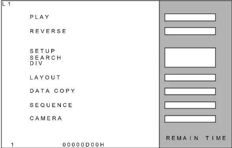
NOTE: * "LAYOUT on the Operation / Setup Menu is not displayed unless LAYOUT MODE of System Setup is set to ACTIVE.
- Using the "3" and "11" keys, move the cursor to "DIV" and push the "7" key. Or click on "DIV."
⇒ The Screen Division Setup screen will be displayed.

* Pushing "SCRN DIV" key also displays the Screen Division Setup screen.
- Using "3," "6," "8," and "11" keys, move the cursor to the desired split pattern and push "7" key. Or, click on the button showing the desired pattern.
⇒ The selected split screen pattern will be displayed.
| Button names | Screen display |
| 1CH ~ 16CH | Full screen display of the selected channel |
| 4SEG A | 4-split screen display A |
| 4SEG B | 4-split screen display B |
| 4SEG C | 4-split screen display C |
| 4SEG D | 4-split screen display D |
| 9SEG A | 9-split screen display A |
| 9SEG B | 9-split screen display B |
| 16SEG | 16-split screen display |
| CANCEL | Go back to Operation Setup Menu |
Automatic Sequence Display
- Pushing the "SEQ DISP" key automatically changes the monitor display according to the setup.
* As for the setup method, see “Automatic Sequence Setup” under “Screen Display Setup” (→P.73)
- Changing the screen to another mode finishes the Automatic Sequence.
PTZ Camera Control
This display function is possible for Monitor 1 in the single screen and the live feed display mode. It is not available for Monitor 2.
You can operate the [X2] button (ZOOM) without connecting to a PTZ camera.
- Push the "CAM" key.
⇒The camera control screen is displayed.

- Click an arrow button, move to the position where you want an enlarged display and click the "+" or "-" button.
⇒Every time you press “+” or “-” button (ZOOM), the image is displayed by plus or minus two times.
→Pushing the X2 button enlarges the center image.
⇒Pushing “+” or “-” button (FOCUS) allows you to adjust focusing.
⇒Pushing “+” or “-” button (FOCUS) enables auto focusing.
⇒Pressing “+” or “-” button (IRIS) allows you to adjust the aperture.
→Pushing "AUTO" button (IRIS) enables automatic adjustment of the aperture.
-
Pushing "3", "6", "8" or "11" key allows you to move in the enlarged area. Drag the mouse to move in the enlarged area.
-
Push the "CAM" key again to exit from the camera control mode.
• Following is how to select and operate from the Operating Menu screen:
- Push the "MENU" key. Or, click the right button on the mouse.
⇒ The Operation / Setup Menu will be displayed.
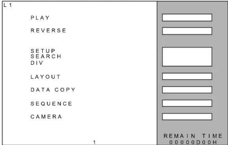
NOTE: * "LAYOUT" on the Operation / Setup Menu is not displayed unless LAYOUT MODE of System Setup is set to ACTIVE.
- Using "3" and "11" keys, move the cursor to the "CAMERA" button and push "7" key. Or, click on the "CAMERA" button.
⇒ The Camera Control screen will be displayed.
* Pushing "CAM" key in the single screen mode also displays the Camera Control screen.
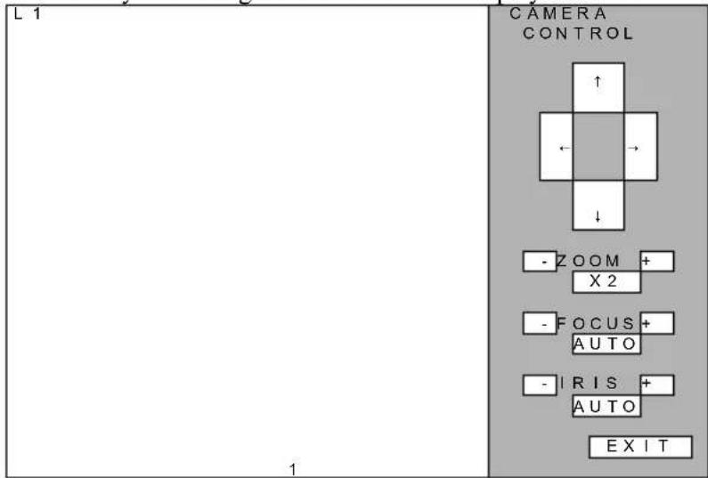
- Using the arrow buttons (↑, ↓, ←, →), move the camera position to the desired location.
ZOOM (+/-): Changes PTZ camera's zoom.
ZOOM (X2): "X2" - 2X digital zoom.
FOCUS (+/-): Moves the camera focal point.
FOCUS (AUTO): Automatic focus
IRIS (+/-): Changes the camera iris.
IRIS (AUTO): Automatic iris
- For ending Zoom mode, push the "CAM" key once again or click the "EXIT" button. Push the "EXIT" key again ton exit from the camera control mode.
2X Digital Zoom Display
This display function is possible for Monitor 1 in full screen display mode. It is not available for Monitor 2.
- Click "X2" button in the Camera Control screen.
2X zoom image will be shown.
-
Using the mouse, or "3," "6," "8," and "11" keys, the zoomed section can be moved.
-
For ending Zoom mode, push the "CAM" key once again.
Viewing Live Feeds from Monitor 2
Monitor 2 shows live feeds at all times.
- Push the "MON 2" key.
→The display will be switched to the panel operation for Monitor 2. While panel operation of Monitor 2, the “MON 2” key lights up.
- Push the "MON 2" key once again.
⇒ The display will be switched to the panel operation for Monitor 1. The indicator of the "MON 2" is turned off.
Recording cording
This operation records live feeds onto hard disk.
Two types of recording modes are available; Manual Recording and Automatic Recording.
- Manual Recording: Recording begins when the “Recording” key is pushed.
- Automatic Recording: Recording begins automatically according to the schedule (continue, alarm input, and motion) set up for each camera.
Screen Display During Recording
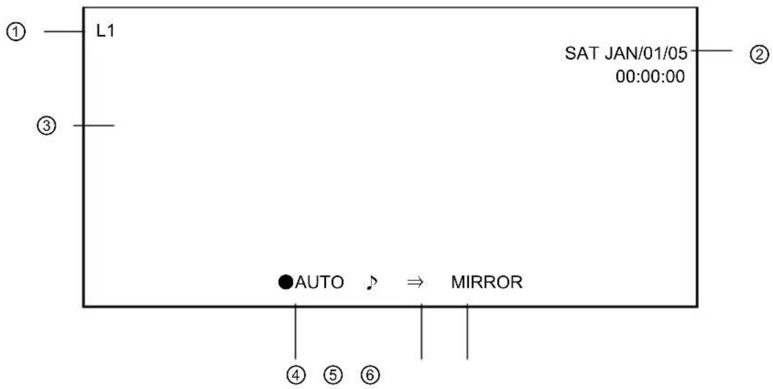
| No. | Names Description | |
| 1 | Channel No. Indicates the | channel of which the footage is being displayed.L indicates live feed. |
| 2 | Current Time Indicates the | current time.The location can be changed by OSD display setup (→P.70) |
| 3 | Live feed Shows live feed | In case no video image is input, “E L M O” logo is displayed. In the event of video loss, “Video Loss” sign is displayed. |
| 4 | Recording Status Indication | Indicates recording status.AUTO: Automatic recording in progressMANUAL: Manual recording in progress♪: Sound recording in progress |
| 5 | Overwrite Recording Setup Indication | Indicates overwrite setup status○: To overwrite⇒: Not to overwriteOverwrite setup can be adjusted under “Recording Setup.” (→P.59) |
| 6 | Recording Mode Indication | Indicates hard disk recording modeNothing displayed: Extended recordingMIRROR: Mirroring recordingRecording mode is set up using the hard disk formatting method.(→P.89 “How to Format Hard Disk”) |
Note
- The display location of ② above or the indications for ④ to ⑥ can be undisplayed or displayed back by OSD Display Setup (→P.70)
Manual Recording
- Pushing the "Recording" key once again stops the recording.
- Push the "Recording" key during live feed display or playback.
⇒ “RECORDING” indicator lights up and manual recording begins according to the recording setup.
Note
Pushing the “Recording” key during automatic recording switches to manual recording mode. When the automatic recording conditions (continue, alarm, or motion) happen during manual recording, these do not start recording.
Using Automatic Recording Mode
Set the continue recording, alarm recording and motion recording conditions for each camera. ( See P.61 for setting up the conditions)
⇒ When the setup conditions happen, automatically begins recording.
- Continue Recording
Timer recording begins when the set time for automatic recording comes.
When alarm signal or motion detection is input while the alarm or motion mode is set in addition to the timer setup, alarm or motion recording begins. When the alarm or motion recording ends while it is still within the timer setup, the recording mode is shifted to timer recording.
- Alarm Recording
When alarm signal is input to the set channel, alarm recording begins.
In case the buzzer sound output is set in “EFFECT” under “System Setup,” the buzzer sounds. (The buzzer can be deactivated using the “STOP” key)
When another alarm input or motion detection happens during alarm recording, the newly input alarm recording or motion recording begins.
- Motion Recording
When a movement is detected within the detection area on the screen, motion recording begins. In case the buzzer sound output is set in “EFFECT” under “System Setup,” the buzzer sounds. (The buzzer can be deactivated using the “STOP” key)
When alarm input or motion detection happens during motion recording, the recording mode is shifted to the newly input alarm recording or motion recording.
Caution
- Extended recording is stored on HDD-A by priority. As HDD-A becomes full, the data is next stored on HDD-B. In case expansion hard disk units are mounted, the recording is stored in the order of HDD-C → HDD-D → HDD-E → HDD-F.
- When synchronizing signal of video input cannot be detected, the equipment regards it as video defect, lighting up Alarm Indicator, Buzzer sound, Alarm Input, and recording of error log.
- When the recording settings are changed, the recording will be finished and the settings will be initialized even if the recording is in process. When the pre-recording is is process, the recording will restart from the time when the settings are changed.
Playback ayback
Below explains how to play back recorded video. Playback is also possible during recording. Playback is possible only on Monitor 1. Monitor 2 is not capable of playback.
Caution
- Channel whose number begins with "PB" shows playback video. Display arrangement can be done in "LAYOUT" setting.
- Channel that shows live feed is in “live feed mode” and doesn’t playback video.
• To start playback video, please set the screen to playback video in LAYOUT setup.
Screen Display During Playback
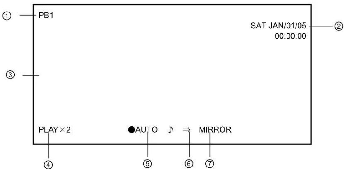
| No. | Names Description | ||||
| 1 | Channel No. Indicates the | channel No. being displayed.PB indicates playback video.Playback video screen is able to set up in LAYOUT.(→P.31) | |||
| 2 | Current Time Indicates the | time of recording.The location can be changed by OSD display setup (→P.70) | |||
| 3 | Showing Video Being Played Back | Shows the playback videoWhen no video is input, the screen shows black color full screen | |||
| 4 | Playback Speed | Indicates the speed of playbackThe speed of fast playback is indicated as shown below: | |||
| PLAY | Forward | (×1) | REVERSE | ||
| PLAY×2 | Forward | (×2) | REVERSE×2 | ||
| PLAY×4 | Forward | (×4) | REVERSE×4 | ||
| PLAY×8 | Forward | (×8) | REVERSE×8 | ||
| PLAY×1 min Forward (1min.) REVERSE×1 min Backward (1 min) | |||||
| PLAY×10 min | Forward (10 mins) | REVERSE×10 mins | Backward (10 mins) | ||
| 5 | Recording Status Indication | Indicates recording status.●AUTO: Automatic recording in progressMANUAL: Manual recording in progress♪: Sound recording in progress | |||
| 6 | Overwrite Recording Setup Indication | Indicates overwrite setup status○: To overwrite⇒: Not to overwriteOverwrite setup can be adjusted under “Recording Setup.” (→P.59) | |||
B
Backward
Backward
Backward
| 7 | Recording ModeIndication | Indicates hard disk recording modeNothing displayed: Extended recordingMIRROR: Mirroring recordingRecording mode is set up using the hard disk formatting method.(→P.89 “How to Format Hard Disk”) |
Note
The display location of ② above or the indications for ④ to ⑦ can be undisplayed by changing the OSD Display Setup (→ P.70)
Playback/Stop Playback
-
During ELMO log is displayed in playback video screen, push the “||▶ (Playback)” key or “◀ || (Reverse playback)” key. Playback video screen is able to set up in TRIPLEX.(→P.31) ⇒ Playback or Backward playback begins.
-
Pushing the “■ (Stop)” key stops playback and returns to ELMO logo display. Pushing the “◀ ||” or “||” key pauses the playback.
- Following is how to control from the Operation Menu Display.
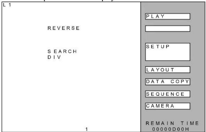
- Push the "MENU" key. Or, click the right button on the mouse. ⇒ The Operation / Setup Menu will be displayed.
-
Playback: Using the "3" and "11" keys, move the cursor to the "PLAY" button, and push the "7" key. Or click on the "PLAY" button. Backward playback: Using the "3" and "11" keys, move the cursor to the "REVERSE" button, and push the "7" key. Or click on the "REVERSE" button. For changing channels: Click on the "DIV" button. After the Screen Division Setup is displayed, select the desired channel. Click on the "LAYOUT" button. After Camera Selection Menu is displayed, select the channel to be played back.
-
Pushing the "STOP" button stops the playback.
Note
- Playback begins from the point where the last playback or backward playback stopped. When the playback continues to the beginning or the end of the recorded data, playback stops and returns to "E L M O" logo displayed.
- When the power is turned on or the point of the last playback or backward playback has been overwritten, playback starts from the oldest point and backward playback starts from the newest point. While overwrite recording is in progress, playback cannot be conducted. Conduct Search and then play back.
- Pushing “▶” key skips to the oldest point and begins playback. Pushing the “◀” key skips to the newest recorded point and begins backward playback.
NOTE: "LAYOUT" is not displayed unless LAYOUT MODE of System Setup is set to ACTIVE.
Changing Playback Speed
- By using Jog Dial:
During playback, turning Jog Dial in the FF (Forward) direction changes the speed of forward playback as follows:
$$ \text { “ } - 1 0 \mathrm{mins} \rightarrow - 1 \mathrm{min} \rightarrow - 8 \times \rightarrow - 4 \times \rightarrow - 2 \times \rightarrow 1 \times \rightarrow 2 \times \rightarrow 4 \times \rightarrow 8 \times \rightarrow 1 \mathrm{min} \rightarrow 1 0 \mathrm{mins} $$
During playback, turning Jog Dial in the REW (Backward) direction changes the speed of backward playback as follows:
$$ " 1 0 \min s \rightarrow 1 \min \rightarrow 8 \times \rightarrow 4 \times \rightarrow 2 \times \rightarrow 1 \times \rightarrow - 2 \times \rightarrow - 4 \times \rightarrow - 8 \times \rightarrow - 1 \min \rightarrow - 1 0 \min s" $$
- By using Shuttle Dial:
Turing Shuttle Dial during playback in the REW (Backward) or FF (Forward) direction plays backward or forward from normal speed to 8×, 1 minute, and 10 minutes.

Caution
- Fast playback might not necessarily be played at the indicated speed.
Playback Frame by Frame
- By using Jog Dial:
Turing Jog Dial in the REW (Backward) or FF (Forward) direction during Pause plays still images frame by frame.

Playback at Fast Speed
• Using Shuttle Dial
While playback is paused, turning the Shuttle Dial in REW (backward) or FF (forward) direction, still images are played back at a fast speed.
Display in Split Screen
Footages from multiple cameras are displayed on monitor in split screen.
The control method is the same as "Display in Split Screen" under "Viewing Live feed." (See P.20)
How to Use LAYOUT Function
During split screen display, live feed and playback video can be displayed at the same time. This function is available during split screen display on Monitor 1.
Note
- “LAYOUT” is not displayed as LAYOUT MODE is set to INACTIVE when the product is shipped from the plant. Set LAYOUT MODE of System Setup to ACTIVE to use the LAYOUT function. (→See P.79)
Caution
• A live feed from one camera cannot be displayed on multiple split screens.
- Push the "MENU" key. Or click on it with the right button of the mouse. ⇒ The Operation / Setup Menu will be displayed.

- Using the "3" and "11" keys, move the cursor to the "LAYOUT" button and push the "7" key. Or click on the "LAYOUT" button. ⇒ The Camera Selection Menu will be displayed.

- Using the "3," "6," "8," and "11" keys, move the cursor to the Camera No. where the display is to be changed, and push the "7" key. Or click on the image where the display is to be changed.
| Cursor | PB1 | PB2 |
| PB3 | PB4 |
- Using the "3," "6," "8," and "11" keys, move the cursor to the Camera No. desired to be displayed and push the "7" key. Or click on the No. desired to be displayed.
LIVE indicates live feed and PLAY indicates playback video.
* Selecting the "BACK button returns to the original screen.
- Using the "3," "6," "8," and "11" keys, move the cursor to the "BACK" button and push the "7" key. Or click on the "BACK" button.
⇒ The live feed of the selected channel will be displayed on the split screen.
(Example : the live feed from L5 is displayed on the PB1 playback video area)
| L5 | PB2 |
| PB3 | PB4 |
Finishing LAYOUT Function
- Push the "MENU" key, or right-click on it using the mouse.
⇒LAYOUT Setting mode (End process) screen is displayed.
| L 5 PB 2 BACK EXIT | |
| PB3 PB 4 |
- Using the "3," and "11" keys, move the cursor to the "EXIT" button and select it by pushing the "7" key. Or, click on the "EXIT" button.
⇒LAYOUT function is finished and split screens are displayed on the monitor.
* Selecting the "CANCEL" tab displays Camera Selection Menu.
Search and Playback Recorded Video
Below explains how to search and play back recorded video.
Note
- After LOGIN to the recorded video search screen, the LOGIN status stays until “LOGOUT” is pressed. User authentication is not required if you search recorded video again under the LOGIN status.
- If you have returned to the live screen without logging out, you will be automatically logged out when the search login time (the value set at factory shipment is 5 minutes) has passed. You will be automatically logged out when the search login time has passed without any entry on the recorded video search screen.
- You can set and change the search login time with AUTO LOGOUT TIME. (→See P.55)
- While displaying live feedor playback video image, push the "SEARCH" key.
Or, pushing the "MENU" key or right click on it shows the Operation / Setup Menu, and then select the "SEARCH" button.
⇒ The User Name Entry Screen will be displayed.
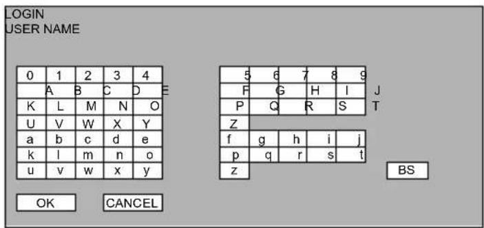
- Enter the user name. Using the "3," "6," "8," and "11" keys, move the cursor to the desired letters and select by pushing the "7" key.
When using a mouse, click on the desired letters.
⇒ The entered letters are displayed on the screen.
- Using the "3," "6," "8," and "11" keys, move the cursor to the "OK" button and select by pushing the "7" key. Or, click on the "OK" button.
⇒ The Password Entry screen will be displayed.

- Enter the password. Using the "3," "6," "8," and "11" keys, move the cursor to the desired letters and select by pushing the "7" key.
When using a mouse, click on the desired letters.
⇒ The entered password is displayed with asterisk “*.”
- Using the "3," "6," "8," and "11" keys, move the cursor to the "OK" button and select by pushing the "7" key. Or, click on the "OK" button.
⇒ The Record Search Item Entry screen will be displayed.

- Specify the search criteria.
Using the "3," "6," "8," and "11" keys to move the cursor and pushing the "UP" or "DOWN" key changes the setup.
When using a mouse, click on the item desired to be changed. Click on it or right click changes the setup.
The setup items are as follows:
| Items | Description |
| START DATE | It is for setting up the starting date and time for search.The initial setup is the oldest data. While overwriting, START DATE is set to 2000/1/1 0:0:0 or the date of the video which was just overwritten. This date is initialized to 2000/1/1 0:0:0 when the PLAY DISK is changed or HDD is formatted. If the search result is happen to be the OVERWRITING Point, START DATE is updated by the new date of the OVERWRITING Point.Selecting “CLEAR” returns to oldest START DATE. |
| END DATE | It is for setting up the ending date and time for search.The initial setup is the present time. Selecting “CLEAR” returns to it. |
| EVENT | It is for setting up event conditions.ALARM: Alarm input recordingMOTION: Motion detection recording.CONTINUE: Continue recordingMANUAL: Manual recordingALL: All event |
| CAM | It is for selecting Camera No.CAM 1~16: The selected camera is designated as search criteria.ALL: All cameras are designated as search criteria. |
Caution
• In case EVENT and CAM are set to ALL, the video of the oldest date between START DATE and
END DATE is displayed. Otherwise the video of the oldest event between START DATE and END DATE is displayed.
- Push the “SEARCH” button. Using the “3,” “6,” “8,” and “11” keys, move the cursor to the “SEARCH” button and select it by pushing the “7” key. Or, click on the “SEARCH” button. Search begins on the specified criteria, and paused recording image, preceding and nearest the specified time, is displayed. When no recording data is found for the search criteria, “NO HIT!” sign is indicated above the SEARCH key of the screen. If you see “OVERWRITING”, the target data is under overwriting and you may be able to access the later time. In this case START DATE is updated by the date time of the overwriting point.
* Pressing "LOGOUT" exits from the search screen and logs out of it.
* Pressing “BACK” returns to the live screen without performing a search. However, the screen is not logged out until the search login time has passed. Pressing the “SEARCH” key again without logging out displays the recorded video search screen without user authentication.
- The found recorded video image in pausing status can be played back forward or backward in the same operation procedure as normal playback.
Caution
- In case more than one data registered with the same recording date are stored in HDD as a result of recording while the time setup was backdated, no data may be found in Date based search.
• To start playback video, please set the screen to playback video in TRIPLEX setup. - The LOGIN status stays until the search login time has elapsed unless you press “LOGOUT” to log out. Press “LOGOUT” to finish the recorded video search.
You can set the search logout time with AUTO LOGOUT TIME. (→See “List of Menu functions” on P.55)
Copy Function
This function transfers recorded data on HDD to USB media connected to ARCHIVE port. This function transfers data to USB media connected to USB2 Port (ARCHIVE) or to DVD.
Caution
- USB
Connect USB media to the ARCHIVE port.
Only mass storage class is compatible.
The used media must be formatted in FAT12/FAT16 and the compatible interface must be USB2.0/1.1.
The copying function copies an easy viewer application (VIEWER.EXE) and the intended video data.
• DVD
Data can be output to DVD-R/DVD-RW. Additional writing is not possible.
The copying function copies an Easy Viewer application (Resizeviewer.exe) and the intended video data. The application includes a user activated video tampering detection function.
DVD comes with data for alteration check. Since the data does not carry data for checking, when conducting alternation check on the data copied from DVD results in error. Alterations can be checked using the Easy Viewer application.
During DVD copying, recording is possible but playback cannot be done.
How to Copy
- Connect USB media to this equipment.
In case copying onto a DVD disc, insert it in the DVD drive. - Push the "MENU" key. Or, right click on it with a mouse.
⇒ The Operation / Setup Menu will be displayed.

- Using the “3” and “11” keys, move the cursor to the “DATA COPY” button and push the “7” key. Or, click on the “DATA COPY” button.
⇒ The User Name Entry Screen will be displayed.
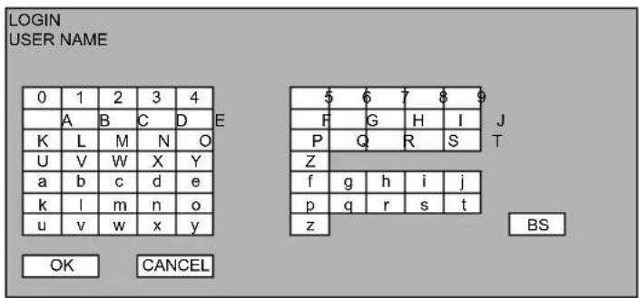
- Enter the user name. Using the "3," "6," "8," and "11" keys, move the cursor to the desired letters and select by pushing the "7" key.
When using a mouse, click on the desired letters.
→ The entered letters are displayed on the screen.
- Using the "3," "6," "8," and "11" keys, move the cursor to the "OK" button and select by pushing the "7" key. Or, click on the "OK" button.
⇒ The Password Entry screen will be displayed.

- Enter the password. Using the "3," "6," "8," and "11" keys, move the cursor to the desired letters and select by pushing the "7" key.
When using a mouse, click on the desired letters.
⇒ The entered password is displayed with asterisk “*.”
- Using the “3,” “6,” “8,” and “11” keys, move the cursor to the “USB” or “DVD” button and select by pushing the “7” key. Or, click on the “USB” or “DVD” button.
⇒ The Data Copy Item Entry screen will be displayed.
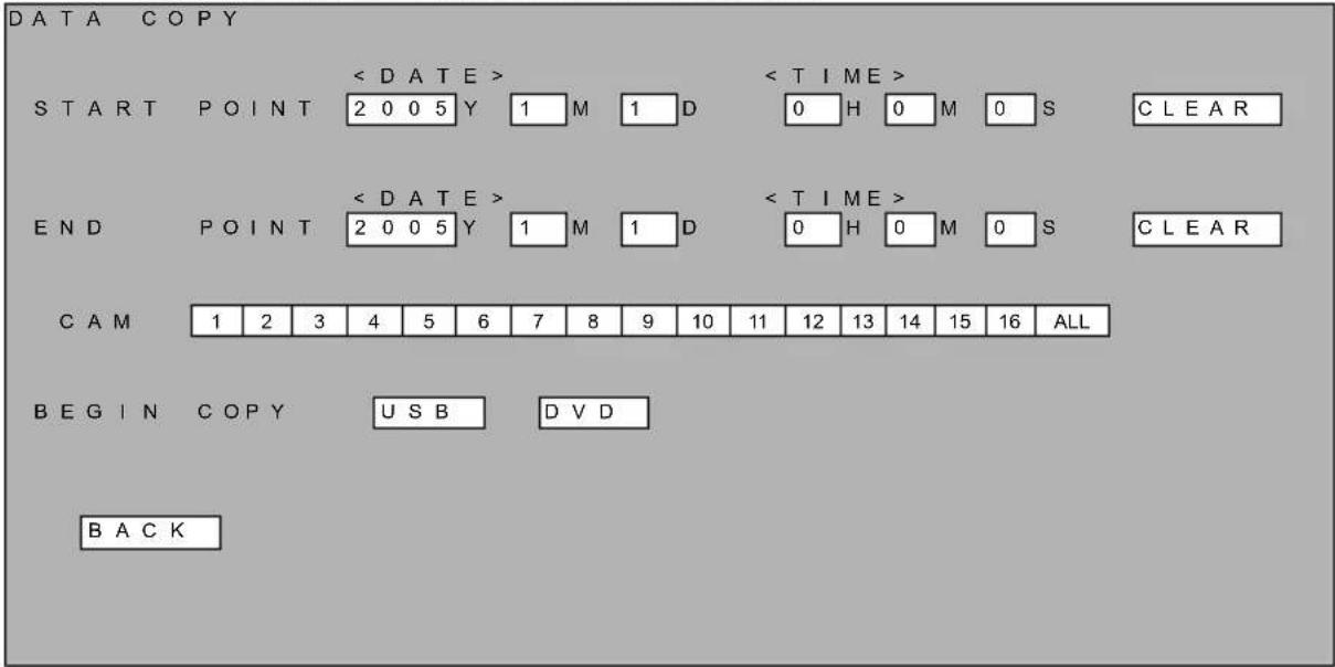
- Specify the starting and ending data and time of data to be copied and the camera.
Using the “3,” “6,” “8,” and “11” keys to move the cursor and pushing the “UP” or “DOWN” key changes the setup.
When using a mouse, click on the item desired to be changed. Click on it or right click changes the setup.
The setup items are as follows:
| Items | Description |
| START POINT | It is for setting up the starting date and time of copying data.The initial setup is the oldest data. Selecting “CLEAR” returns to it. |
| END POINT | It is for setting up the ending date and time of copying data.The initial setup is the present time. Selecting “CLEAR” returns to it. |
| CAM | It is for selecting Camera No. More than one camera can be selected.CAM 1~16: The selected camera is designated for search criteria.ALL: All cameras are designated for search criteria. |
| USB/DVD | Specifies the media onto which the selected data is to be copied.USB: Copying will be conducted onto USB media.DVD (option): Copying will be conducted onto a DVD. * If the DVD drive is not mounted, the DVD button does not appear. |
Caution
- In case more than one data is registered with the same recording date are stored in HDD as a result of recording while the time setup was backdated, the start point and end point may not be specified at times.
-
When USB media or DVD disk is set, click "USB" or "DVD" to start copying.
-
Using the "3," "6," "8," and "11" keys, move the cursor to the "ENTER" button and select by pushing the "7" key. Or, click on the "ENTER" button. Move the cursor to "USB/DVD" with "3", "6", "8" or "11" and finalize with the "7" key. Or, click "USB/DVD".
⇒ Copy begins. The screen turns to the normal screen while the copy is processing, and the message “COPYING” is displayed on the lower part of the screen. When displaying the menu, the copy progress is displayed in percent figures on the play menu part.
- After the copy is finished, select the "COPY STOP" from the MENU, and return to the Operation / Setup Menu.
Stop Copying
- Press the "MENU" key during transfer. Or, right-click the mouse.
⇒The data copy end screen is displayed.
- Pushing the "Stop" key, during data transfer displays Transfer Cancellation Confirmation message. Move the cursor to "COPY STOP" with the "3", "6", "8" or "11" key and finalize with the "7" key. Or, click "COPY STOP."
⇒The transfer stop confirmation message is displayed.
* The transfer stop confirmation message is also displayed when you push the "STOP" key on the normal screen during transfer.

- Stop copying:
Using the cursor key (“3,” “6,” “8,” “11” key), move the cursor to “Yes” and then push the “MENU” key, and the data transfer is stopped and the screen returns to a pausing image.
Continue copying:
Using the cursor key (“3,” “6,” “8,” “11” key), move the cursor to “Cancel” and then push the “MENU” key, and the data transfer resumes.
In the event the copying media becomes full during data transfer, a message, “Copying finished due to no available space in the media” is displayed and the copying is stopped.
In the event an error occurs during data transfer, an error message is displayed and the copying is stopped.
In case USB media is not connected, or the data being copied is overwritten during data transfer, an error message is displayed.
- Pushing the "MENU" key, the screen returns to a paused image.
Image File Format Copied to USB Media
The images copied onto USB media are stored in the following format:
"EMR_xxxx" folder is generated in the root directory.
xxxx indicates “0001\~9999.” In case EMR_xxxx folders already exist, a new folder is generated while giving a number which is one larger than the largest existing folder number. In case 9999 exists, it results in an error, displaying an error message and cancelling data transfer.
The folders below are added to the "EMR_xxxx" folder:
"yyyymmdd" folder
"Camera No." folder
"Hour/Min/Sec, No. + .JPG" * No. is shown in hexadecimal.
JPEG files are stored in the size of 720×240, but the images can be displayed in 720×480 by using the software application which is also stored during data transfer.
Image File Format Copied to DVD
The images copied are stored in the following format:
"EMR_0001" folder is generated in the root directory.
WEB Server Function
Below explains how to use EMR-16 through a WEB browser.
Functions
• Possible to function as a WEB server, to be connected by 3 clients at maximum
• Possible to view live feed by a WEB browser
• Possible to search and play back past recorded video by a WEB browser
• Possible to see and change the Menu setup by a WEB browser
• Possible to download the past video data by a WEB browser
Physical Connection Configuration

flowchart
graph LR
    A["Camera 1"] --> D["Equipment"]
    B["Camera 2"] --> D
    C["..."] --> D
    D --> E["Router"]
    F["Camera 15"] --> D
    G["Camera 16"] --> D
    D --> H["Internet"]
    H --> I["Client"]
    H --> J["Terminal"]
    H --> K["Terminal"]
    H --> L["Terminal"]
    H --> M["Terminal"]
    H --> N["Terminal"]
    H --> O["Terminal"]
    H --> P["Terminal"]
    style H fill:#f9f,stroke:#333
Operation Environment
Browser
Internet Explorer 4.0 or later
Netscape Communicator 4.75 or later
Java
Operates only on Sun JRE 1.5 or later
Login/Logout
- When accessing the equipment's contents for the first time, the certification screen appears.

IN
- Enter the User Name and Password, and click on the "LOG IN" button. The password entered is displayed by the "●" mark. There are two types of certification account; general account and setup account.
- General account (User level): possible to browse only live feed distribution - Setup account (ADMIN level): possible to operate all functions
- After certification is successful, the top page is accessed.
- The top page of general account

- The top page of setup account
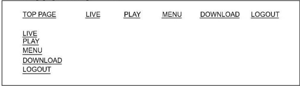
- Select the intended menu
• LIVE Live feeds delivery
- PLAY Playback video delivery
- MENU Setup
• DOWNLOAD Downloading data
- Clicking on "LOGOUT" button logs out. Be sure to log out after finishing the operation. Automatic logout function works for time-out in the case of forced shutdown of PC. The server monitors the access from clients and after 5 minutes pass from the last access, the account is automatically logged out.
Caution
- Entry of wrong User Names or Password does not change the screen display but continues to show the certification screen. In case the maximum number (3 accounts) of clients are accessing, the screen shows an message as shown below and the operation is discontinued.
- Up to one setup account or up to three general account can login at the same time, and therefore, if accessing the equipment while other client has already logged in, the same message is displayed.
BECAUSE IT HAS REACHED THE MAXIMUM NUMBER OF USERS
IT IS NOT POSSIBLE TO OPERATE FROM BROWSER.
PLEASE
TRY
OK
AGAIN
- Pushing the "OK" button returns to the certification screen.
Caution
- Since the automatic logout function uses the built-in clock, if the time setup is changed from the Menu on the equipment or from a WEB menu while a client is logged in, the function may automatically execute logout. Should this occur, please log in again.
LIVE FEED
Through communication with EMR-16, live feeds are distributed. Default display setup is 16-split screen mode.
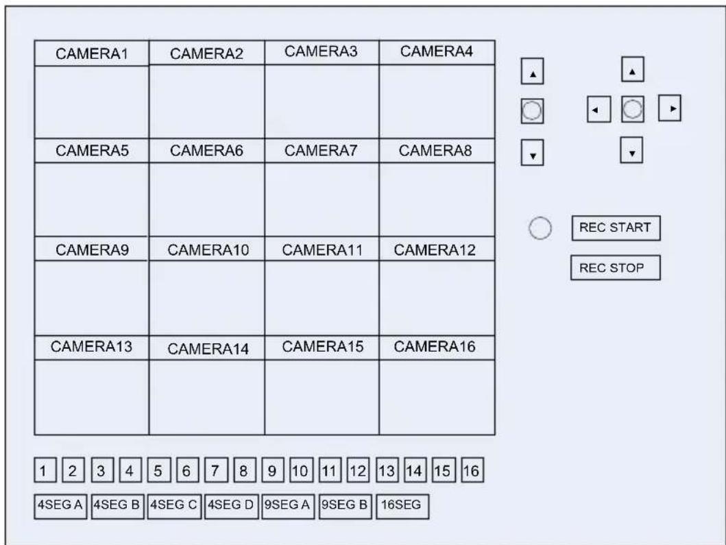
Using the camera switch keys, displaying cameras can be changed:
| Camera No. | Display Screen( ) indicates intial settings | Image Size |
| 1~16 | Full screen display of selected camera 720×480 | |
| 4SEG A 4-split | A (Camera 1~4) 360×240 | |
| 4SEG B 4-split | B (Camera 5~8) | |
| 4SEG C 4-split | C (Camera 9~12) | |
| 4SEG D 4-split | D (Camera 13~16) | |
| 9SEG A 9-split | A (Camera 1~9) 240×160 | |
| 9SEG B 9-split | B (Camera 10~16, 1, 2) | |
| 16SEG 16-split | 180×120 | |
• Start / Stop of Manual Recording
Selecting “REC START” starts manual recording. Pushing the “REC STOP” stops the manual recording.
• Changing the Displayed Channel Location
While in multi-split screen display mode, by right clicking the screen, the location of live feed channel can be changed.
PLAYBACK
Through communication with EMR-16, live feed and playback video can be displayed. This operation is possible only by access in the setup account
The last played video is displayed in a paused image by default, but immediately after the power of the equipment is turned on or when recorded data is not available, a black screen is displayed.
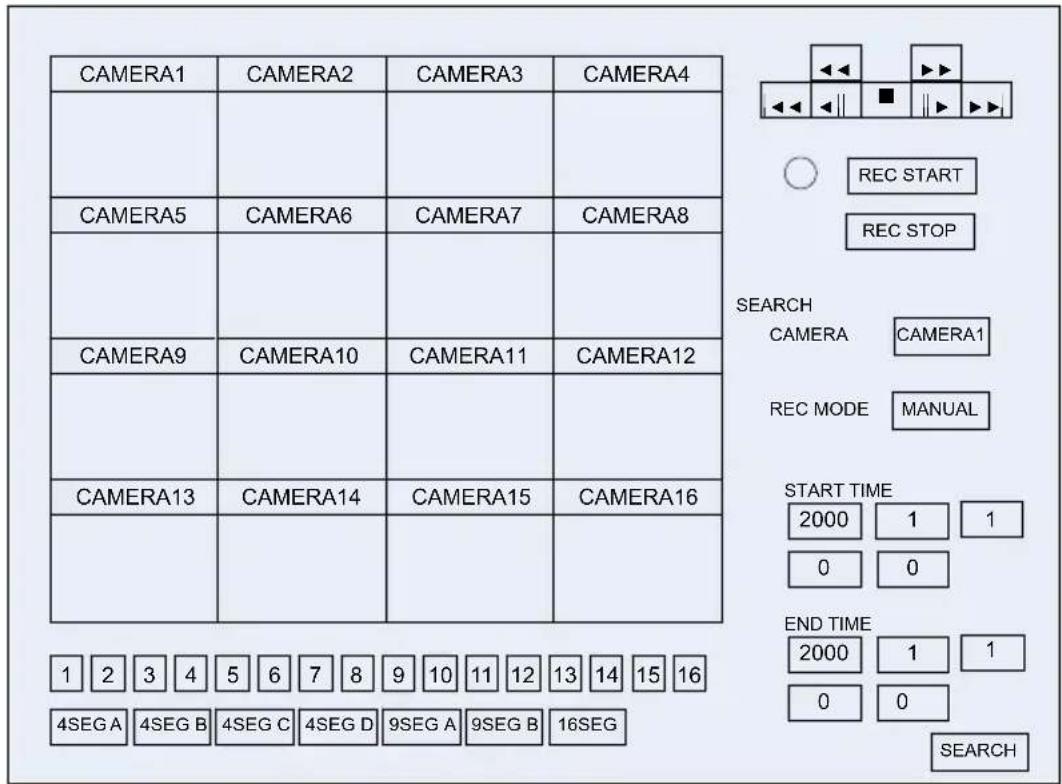
Using the camera switch keys, displaying cameras can be changed:
| Camera No. | Display Screen( ) indicates initial settings | Image Size |
| 1~16 | Full screen display of selected camera | 720×480 |
| 4SEG A 4-split A | (Camera 1~4) 360×240 | |
| 4SEG B 4-split B | (Camera 5~8) | |
| 4SEG C 4-split C | (Camera 9~12) | |
| 4SEG D 4-split D | (Camera 13~16) | |
| 9SEG A 9-split A | (Camera 1~9) 240×160 | |
| 9SEG B 9-split B | (Camera 10~16, 1, 2) | |
| 16SEG 16-split | 180×120 |
- Start / Stop of Manual Recording
Selecting “REC START” starts manual recording. Pushing the “REC STOP” stops the manual recording.
• Changing the Displayed Channel Location
While multi-split screen display mode, by right clicking the screen, the location of live feed channel can be changed.
- Playback Operation
Playback operations shown below are possible using the playback keys:
◀ Fast backward playback (2× →4× →8×)
▶▶ Fast forward playback (2×→4×→8×)
Frame by frame backward playback while pausing
Pause
▶ Frame by frame forward playback while pausing
A pausing display of the oldest video image
▶ A pausing display of the newest video image
Note
- When the position of the oldest or the newest recorded data is reached during forward or backward playback, a pausing display of the final video image is shown.
- Search Operation
This is to conduct search and playback of recorded video. Displayed in STOP mode.
-
By specifying the items below, search can be conducted:
The recorded image closest to and newer than the designated time will be displayed.
| Items | Description |
| CAMERA | It is for selecting Camera No. More than one camera can be selected.CAM 1~16: The selected camera is designated as search criteria.ALL: All cameras are designated as search criteria. |
| REC MODE | It is for setting up event conditions. More than one event can be selected.MANUAL: Manual recordingMOTION: Motion detection recordingALARM: Alarm input recordingCONTINUE: Scheduled recordingALL: All event conditions |
| START TIME It is for setting the starting date and time for search. | |
| END TIME It is for setting the ending date and time for search. | |
- Duplex Display
During playback in split screen mode, one of the split screens can be changed to live feed thus displaying playback video and live feed at the same time. Right-click on the screens to open the pop-up menu.

Selecting one out of Cameras 1\~16 on the pop-up menu, the screen showing the pop-up menu is changed to the selected live feed. To cancel the live feed, select "Cancel" from the pop-up menu. The live feed display location is separately stored for each split screen.
Caution
- During full screen display mode, duplex setup is not available.
- Not all split screens can be changed to live feed display. The operation for changing the last split screen to live feed on the pop-up menu results in error.
• A live feed from one camera cannot be displayed on more than one screen.
MENU
The Menu setup of the equipment can be viewed and changed. This function is available only when login with a setup account.
The Menu below is displayed. By clicking on one of the buttons, the setup screen is displayed.
Main Menu

flowchart
graph TD
    A["Recording setup"] --> B["Recording condition setup"]
    A --> C["Recording schedule setup *"]
    A --> D["Concurrent recording camera setup *"]
    A --> E["Holiday setup screen"]
    A --> F["Motion setup *"]
    G["Screen display setup"] --> H["OSD display setup"]
    G --> I["Monitor output setup"]
    G --> J["Auto sequence setup"]
    G --> K["Camera name setup"]
    L["Network setup"] --> M["E-mail setup"]
    L --> N["System setup"]
    L --> O["Log display"]
    O --> P["Recording log"]
    O --> Q["Error log"]
    O --> R["Startup log"]
    O --> S["User log"]
    T["Equipment maintenance"] --> U
* "AUTO LOGOUT TIME" is displayed on the "System Setup" screen.
* “Recording schedule setup,” “Concurrent recording camera setup,” and “Motion setup” work with Java Applet.
See P.59 under "Recording Setup" for specific setup contents.
Caution
- The setup items below cannot be viewed or changed from the Menu of the WEB server function Network setup: IP address, subnet mask, default gateway
Equipment maintenance: Hard disk formatting, setup reset, log reset, setting external output, setting external input - The setup operation is possible only when the operation mode on the equipment is live and recording is not in progress. The setup operation is possible only when the operation mode on the equipment is in live feed display and recording is not in progress.
- DOWNLOAD
Data recorded in the past stored on the equipment can be downloaded onto the hard disk of a client PC. This function can be accessed only with a setup account.
Since video download uses applet with signature, a dialog for confirming whether the applet with signature is trusted or not is displayed.

* Some versions of Java might show a different message from the above.
Selecting "Yes" enables video download.
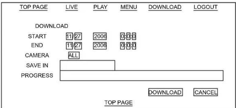
Video data are transferred to and stored onto the hard disk of a client PC in the pixel size of 720 × 240 , but the images can be displayed in 720 × 480 by using the software application which is also stored during download. See JPEG Display Software “Resize Viewer” ( P.99) for more details about this software.
- After selecting the start time, end time, camera and destination to save, select the "DOWNLOAD" button.
⇒ Download begins. During download, the status is displayed in “PROGRESS” section. Pushing the “CANCEL” key stops the download.
The downloaded data is stored in a folder at the destination with the following folder name and file name as multiple JPEG files.
"Camera No." folder "04021300000001.JPG"
Caution
- In case the data is not stored continuously from the start time to end time, the progress might not be displayed accurately
E-Mail Function
In the event of recording start due to alarm input or motion detect or internal alarm generation, e-mail is sent containing the messages shown below:
See “E-mail Setup” (→P.76) under the Menu for detailed information of e-mail setup
Subject:
"EMR-16"
Sent Information
| Generated alarm “Sent information” | |
| Detecting Internal alarm | “REPORT ERROR” |
| Detecting Alarm 1 “REPORT ALARM 1” | |
| Detecting Alarm 2 “REPORT ALARM 2” | |
| Detecting Alarm 3 “REPORT ALARM 3” | |
| Detecting Alarm 4 “REPORT ALARM 4” | |
| Detecting Alarm 5 “REPORT ALARM 5” | |
| Detecting Alarm 6 “REPORT ALARM 6” | |
| Detecting Alarm 7 “REPORT ALARM 7” | |
| Detecting Alarm 8 “REPORT ALARM 8” | |
| Detecting Alarm 9 “REPORT ALARM 9” | |
| Detecting Alarm 10 “REPORT ALARM 10” | |
| Detecting Alarm 11 “REPORT ALARM 11” | |
| Detecting Alarm 12 “REPORT ALARM 12” | |
| Detecting Alarm 13 “REPORT ALARM 13” | |
| Detecting Alarm 14 “REPORT ALARM 14” | |
| Detecting Alarm 15 “REPORT ALARM 15” | |
| Detecting Alarm 16 “REPORT ALARM 16” | |
| Test sending “TEST” | |
How To Set Up
Below are explanations of the contents and method of setup using the Menu screen.
How to Start and Finish Menu Mode
- During live feed display, push the "MENU" key. Or, right click on it with a mouse. The Operation / Setup Menu will be displayed.

- Using the “3” and “11” keys, move the cursor to the “MENU” button and select it by pushing the “7” key. Or click on the “MENU” button. ⇒ The User Name Entry Screen will be displayed.

-
Enter the user name. Using the "3," "6," "8," and "11" keys, move the cursor to the desired letters and select by pushing the "7" key. When using a mouse, click on the desired letters. ⇒The entered letters are displayed on the screen.
-
Using the “3,” “6,” “8,” and “11” keys, move the cursor to the “OK” button and select by pushing the “7” key. Or, click on the “OK” button.
⇒ The Password Entry screen will be displayed.

- Enter the password. Using the "3," "6," "8," and "11" keys, move the cursor to the desired letters and select by pushing the "7" key.
When using a mouse, click on the desired letters.
⇒ The entered password is displayed with asterisk “*.”
- Using the “3,” “6,” “8,” and “11” keys, move the cursor to the “OK” button and select by pushing the “7” key. Or, click on the “OK” button.
⇒ The Main Menu screen will be displayed.

- Using the "3" and "11" keys, move the cursor to the "ENTER" button of the intended menu and select by pushing it with the "7" key. Or, click on the "ENTER" button.
* Selecting the "BACK" button returns to live feed display.
⇒ The selected screen will be displayed (Below is an example of selecting “REC SETUP”)

Operation of Menu Screen
Below are explanations of basic operation of each screen under the Menu mode
Example) Recording Conditions setup
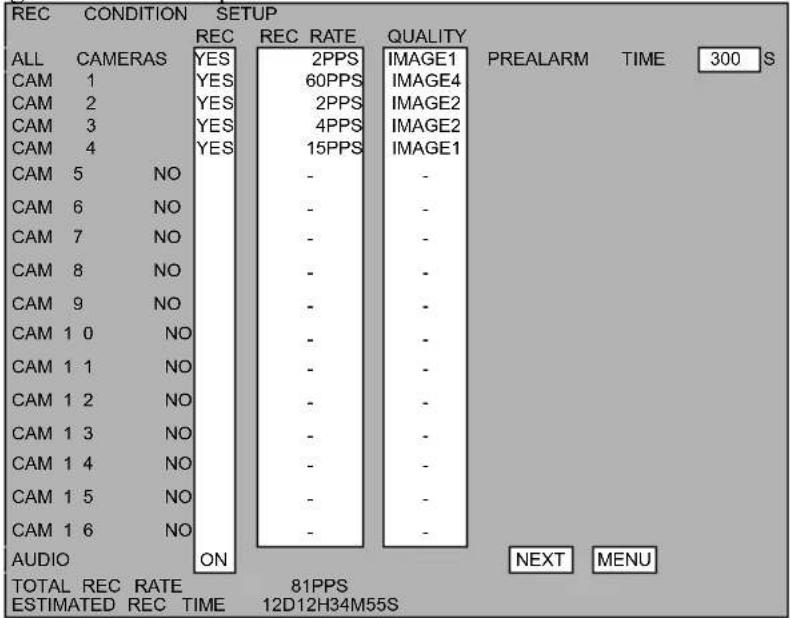
- Move the cursor to the intended item and change the setup.
- Using keys
Using the “3,” “6,” “8,” and “11” keys, move the cursor to the item where the setup is to be changed.
Pushing the “UP” key changes the value. Pushing the “DOWN” key changes the value in the opposite direction.
- Using a mouse
Each click on the item changes the value. Each right click on the item changes the value in the opposite direction.
- Moving to the next screen registers the changed values.
| ENTER | Displays the selected menu screen. |
| NEXT | Displays the next screen |
| PREV | Displays the previous screen |
| MENU | Displays the menu screen for setup |
- Using keys
Using the “3,” “6,” “8,” and “11” keys, move the cursor to the intended button, and select by pushing it with the “7” key.
- Using a mouse
Click on the intended button.
List of Menu Functions
The settings shown in ( ) indicate factory default setup.
| Menu item | Items | Settings | Ref. page | ||
| Recording Setup | OVERWRITE | YES/NO (NO) | |||
| Recording Conditions Setup | REC(For each camera) | YES/NO (YES for all cameras) | |||
| REC RATE(For each camera) | 60PPS, 30PPS, 15PPS, 10PPS, 7.5PPS, 5PPS, 4PPS, 3PPS, 2PPS, 1PPS (7.5PPS for all cameras) | ||||
| QUALITY(For each camera) | IMAGE1~4(IMAGE1 for all cameras) | ||||
| AUDIO | ON/OFF (ON) | ||||
| PREALARM | 0~300 seconds (0 second) | ||||
| Recording schedule(For each camera) | Can be set for each day of the week [Sun to Sat] and specified dates at a 30-minute interval.Start time: 0:00~24:00 (0:00)End time: 0:00~24:00 (24:00) | ||||
| Recording Event:ALARM, MOTION, CONTINUE,ALARM & MOTION, orALARM & CONTINUE | |||||
| POST | DIM99 seconds (default AIRSM) | ||||
| POST TIME MOTION | 0~999 seconds (default: 10S) | ||||
| Concurrent Recording Camera setup Camera setup for simultaneous recording upon occurrence of Events*The camera settings on the diagonal line cannot be turned off. | |||||
| Holiday setup Can be set for each of dates No. 01 to 801/1~12/31 / no setup (No setup)Cannot be set for dates not in existence such as 2/31 | 66 | ||||
| Motion setup Setup for motion detection area | |||||
| Screen Display Setup | MONITOR1 INIT. MODE | POS 1~16, 4SEG A~D,9SEG A~B, 16SEG (default: 16SEG) | |||
| MONITOR2 INIT. MODE | POS 1~16, 4SEG A~D,9SEG A~B, 16SEG (default: 16SEG) | ||||
| FULL SCREEN VIEW SETUP NONE | ALARMMOTIONBOTH (BOTH) | ||||
| FULL SCREEN VIEW PRIORITY FIRSTLAST (LAST) | |||||
| FULL SCREEN VIEW TIME | 0~9, 10, 20, 30, 40, 50, 60, 70, 80, 90,100, 110, 120 seconds / No limit (10 sec) | ||||
| OSD Display Setup | AUDIO | ON/OFF (ON) | |||
| OVER WRITE | ON/OFF (ON) | 70 | |||
| RECORD | ON/OFF (ON) | 70 | |||
| PLAY | ON/OFF (ON) | 70 | |||
| PLAYBACK TIME ONLY/SCREEN/OFF (ONLY) | 70 | ||||
| RECORD TIME RECORD/REMAIN/OFF (REMAIN) 70 | |||||
| HDD MODE ON/OFF (ON) 70 | |||||
| DATE ON/OFF (ON) | |||||
| TIME ON/OFF (ON) | |||||
| DATE OSD POSITION UP/DOWN/LEFT UP LEFT DOWN/RIGHT UP RIGHT DOWN (LEFT UP) | 70 | ||||
| MONITOR1 CAM NAME OFF/NAME/NUM (NAME) 70 | |||||
| MONITOR2 CAM NAME | 70 | ||||
| Monitor output setup | MONITOR1 (For each camera) | ON/OFF (ON) | |||
| MONITOR2 (For each camera) | ON/OFF (ON) | ||||
| Auto sequence setup | MONITOR1 Setup for | each of the Steps 1~22POS 1~16 / 4 SEG A~D, 9SEG A, B / 16SEG (Steps 1~16: POS11~16, Steps 17~: POS1)0~60 seconds (Step 1~22: 3 sec) | 73 | ||
| MONITOR2 | |||||
| Camera Name Setup(For each camera) | 15 letters in cap/small alphabets, numbers, marks(CAMERA1-CAMERA16) | ||||
| Network Setup | IP ADDRESS | 0~255, 4 digits (192.168.0.100) | |||
| SUBNET MASK | 0~255, 4 digits (255.255.255.0) | ||||
| DEFAULT GATEWAY | 0~255, 4 digits (0.0.0.0) | ||||
| PRIMARY DNS SERVER | |||||
| SECONDARY DNS SERVER | |||||
| WEB PORT NUMBER | GENERIC,1024~65535 (GENERIC) | ||||
| LIVE DELIVERY IMAGE | IMAGE1~4 (IMAGE1) | ||||
| TRANSFER RATE | 32Kbps, 64Kbps, 128Kbps, 256Kbps 512Kbps, 1Mbps, 2Mbps, 4Mbps, or UNLIMITED (UNLIMITED) | ||||
| E-mail Setup | SOURCE ADDRESS | 46 letters in cap/small alphabets, numbers, marks (No setup) | |||
| DESTINATION ADR1 | |||||
| DESTINATION ADR2 | |||||
| DESTINATION ADR3 | |||||
| DESTINATION ADR4 | |||||
| SMTP SERVER DOMAIN | 46letters(No setup) | ||||
| POP3 AUTHENTICATION | YES/NO (NO) | ||||
| ENCRYPTION | YES/NO (NO) | ||||
| USER NAME | 23 letters in cap/small alphabets, numbers, marks (No setup) | ||||
| PASSWORD | |||||
| POP3 SERVER DOMAIN | 46letters(No setup) | ||||
| E-mail Sending Setup | SYSTEM ALARM | ON/OFF | 78 | ||
| ALARM1~16 | ON/OFF | 78 | |||
| Test sending | E-mail containing the title, “EMR-16” and main text, “TEST” is sent to the registered addresses | ||||
| System Setup | HD REMAINING TIME | 0~999 hours (1 hour) | |||
| BUZZER EFFECT/NO EFFECT (EFFECT) | (1) | ||||
| ALARM OUTPUT DURING ALARM REC | INTERNAL ALARM LEVEL WARNING ALL (ALL) | ||||
| ALARM OUTPUT TIME DURING ALARM REC | 1 SEC (DURING ALARM REC) | ||||
| Control Camera Setup | TYPE PTC-200C / PELCO-D / OTHER (OTHER) | 80 | |||
| CAM ID | |||||
| User Setup ADMIN | N1-4 Within 10 letters | (1: ELMO, others: blank) | |||
| ADMIN PASS1-4 Within 10 letters (1: ELMO, others: blank) | |||||
| USER1-16 Within 10 letters (All blank) | |||||
| USER PASS 1-16 Within 10 letters (All bkank) | |||||
| REC SETUP | ENABLE/DISABLE (ADMIN: ENABLE, USER: DISABLE) | ||||
| DISPLAY SETUP | ENABLE/DISABLE (ADMIN: ENABLE, USER: DISABLE) | ||||
| NETWORK SETUP | ENABLE/DISABLE (ADMIN: ENABLE, USER: DISABLE) | ||||
| MAIL SETUP | ENABLE/DISABLE (ADMIN: ENABLE, USER: DISABLE) | ||||
| SYSTEM SETUP EN | ENABLE/DISABLE (ADMIN: ENABLE, USER: DISABLE) | ||||
| LOG MENU | ENABLE/DISABLE (ADMIN: ENABLE, USER: DISABLE) | ||||
| MAINTENANCE | ENABLE/DISABLE (ADMIN: ENABLE, USER: DISABLE) | ||||
| SEARCH | ENABLE/DISABLE (ADMIN: ENABLE, USER: DISABLE) | ||||
| DATA COPY | ENABLE/DISABLE (ADMIN: ENABLE, USER: DISABLE) | ||||
| PLAY DISK | PLAY DISK SELECT ALL(LONG ONLY)DISK A/DISK B(MIRROR ONLY) (ALL) | ||||
| LAYOUT MODE | ACTIVE INACTIVE (INACTIVE) | 79 | |||
| Log Viewer | Rec Log DATE TIME | — | 83 | ||
| CH | — | ||||
| STATUS | — | ||||
| Error Log | DATE TIME | — | |||
| CAM | — | ||||
| STATUS | — | ||||
| Start Log DATE TIME | — | ||||
| STATUS | — | ||||
| User Log DATE TIME | — | ||||
| DETAIL | — | ||||
| USER NAME | — | ||||
| Equipment Maintenance | TIME SETUP 2000/1/1~2099/12/31 | (2005/1/1 00:00:00)Cannot be set for dates not in existence such as 2/31 | |||
| HDD RESET | Formats the hard disk (Extended mode) | 89 | |||
| SETUP RESET | Rests the setup 89 | ||||
| LOG RESET | Rests the log 89 | ||||
| EXPORT SETTING Writes the setup on | a connected media | ||||
| IMPORT SETTING Reads the setup from | a connected media | ||||
| DAYLIGHT SAVINGS TIME ON/OFF | (ON) | ||||
| BEGIN Month / Week Day Time | (MAR 2ND SUN 2:00 AM) | ||||
| END Month / Week Day Time | (NOV 1ST SUN 2:00 AM) | ||||
| NTP SERVER DOMAIN Moves to NTP | server domain name input screen. | ||||
| TIME ZONE | Sets the time zone at a 15-minute interval. (-12:00~+13:00) | ||||
| AUTO LOGOUT TIME | 1MIN. / 2MIN. / 3MIN. / 4MIN. / 5MIN. / 6MIN. / 7MIN. / 8MIN. / 9MIN. / 10MIN. / NO Limit (5MIN) | 59 | |||
Main menu screen
Display setting screens from the main menu.
Set the search login time of AUTO LOGOUT TIME.
NOTE
When you access this unit with a WEB browser, set AUTO LOGOUT TIME on the SYSTEM SETUP screen.

| Item | Description |
| REC SETUP | Displays the recording setup screen. (→P60.) |
| DISPLAY SETUP | Displays the screen display setup screen. (→P.69) |
| NETWORK SETUP | Displays the network setup screen. (→P.75) |
| MAIL SETUP | Displays the mail setup screen. (→P.76) |
| SYSTEM SETUP | Displays the system setup screen. (→P.79) |
| LOG VIEWER | Displays the log display screen. (→P.83) |
| MAINTENANCE | Displays the device maintenance screen. (→P.88) |
| AUTO LOGOUT TIME | Set the search login time to execute the automatic logout from the LOGIN status for recorded video search. The search login time is reset and counting starts again every time you operate the recorded video search screen. If you set NO Limit, automatic logout is not executed.Setting range: 1MIN., 2MIN., 3MIN., 4MIN., 5MIN., 6MIN., 7MIN., 8MIN., 9MIN., 10MIN., NO Limit |
| BACK | Returns to the live display screen. |
Recording Setup
Below are instructions for recording setup:

| Items | Settings |
| REC CONDITION SETUP | Displays the recording setup screen (→P.61) |
| SCHEDULE SETUP | Displays the schedule setup screen (→P.63) |
| CONCURRENT SETUP | Displays the concurrent recording camera (→P.65) |
| HOLIDAY SETUP | Displays the holiday setup screen (→P.66) |
| MOTION SETUP | Displays the motion recording setup screen (→P.67) |
| OVERWRITE | Setup for enabled or disabled of hard disk overwriteYES: When the hard disk is full, recording continues while overwriting the oldest recorded dataNO: When the hard disk is full, recording discontinues* When the remaining time (recordable time remaining on the disk) goes below the remaining time setup under the System Setup, the “HDD” indicator begins flickering. When the disk free space is all gone, the “HDD” indicator lights up and the recording stops.(See “System Setup” →P79 When the remaining time (recordable time remaining on the disk) goes below the setup remaining time specified under the System Setup, the “HDD” indicator lights up in orange color. When the free disk space is all gone, the “HDD” indicator lights up in red color and the recording stops.) |
| MENU | Returns to the Main Menu Screen |
Recording Conditions Setup
Recording conditions such as image quality or intervals can be set up for each camera.
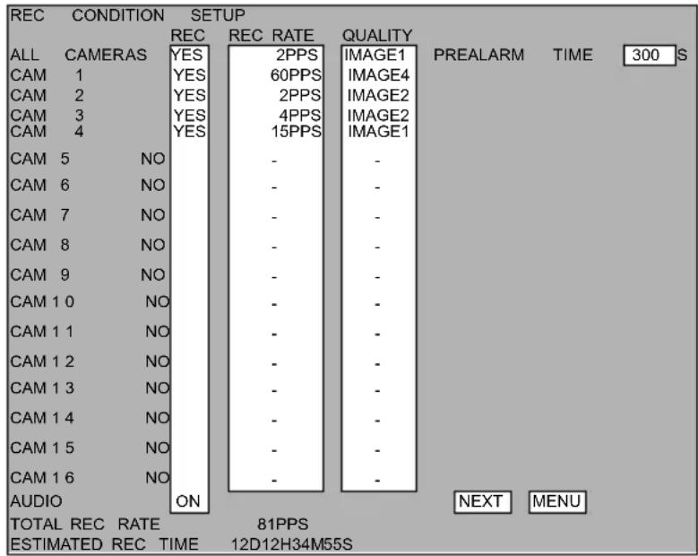
(See P.99 “Recording Time Table”) The shorter the recording interval is, the shorter the total recordable time becomes, and the longer the recording interval, the longer the total recording time. The higher the image quality is set, the shorter the total recordable time is available, and the lower the image quality, the longer the total recordable time is.
| Items | Settings |
| REC | Setting up whether to conduct recordingYES : Allows Manual recordingNO : Does not allow Manual recording* When set in “NO,” the indication on the right shows “—” and the cursor cannot be moved there. |
| REC RATE | Setting up recording intervals for each camera during recordingThe shorter the interval is set, the shorter the recordable time.Setup range: 60, 30, 15, 10, 7.5, 5, 4, 3, 2, and 1 PPS* PPS = The number of images recorded per 1 second |
| QUALITY | Sets image quality for each camera during recordingThe higher the image quality is set, the shorter the recordable time.Setup range: IMAGE 1~4 |
| AUDIO | Setting up whether to record sound during recordingON : Sound is recordedOFF : Sound is not recorded |
| PREALARM | Setting up the number of seconds before alarm input when the recording is to beginSetup range: 0~300 seconds |
| NEXT | Displays the Recording Schedule Setup Screen (→P.63) |
| MENU | Returns to the Main Menu Screen |
• TOTAL REC RATE
Displays a total of the recording rates of the setup cameras. The maximum rates are 120PPS and this number cannot be exceeded.
Video is recorded in the same field if it is recorded in the recording rate other than 60PPS. Therefore, you may not set a combination of recording rates that do not allow allocating the same field. In that case, set TOTAL REC RATE to 118 or less.
• ESTIMATED REC RATE
Displays a reference remaining recordable time based on a calculation of the current recording setups and the hard disk free spaces.
■ Setup of Image Quality
The “File Size” indicates the size of data after compression, and the larger the size is the image quality is finer, closer to the original video footage.
IMAGE 1 indicates the highest image quality although the recording time is shorter than other lower settings. IMAGE 4 conversely is the lowest yet suitable for Extended recording.
Setups should be adjusted according to the required recording conditions. (See P.108 “Recording Time Table”)
| Image Quality File Size | |
| IMAGE 1 64KB | |
| IMAGE 2 48KB | |
| IMAGE 3 32KB | |
| IMAGE 4 16KB | |
Recording Schedule Setup
Automatic recording conditions can be set up for each camera.

- Select from "CAM1\~16" the camera for which schedule is set up.
- Select the event for automatic recording and set up the day of the week and time. Setup is possible in units of 30 minutes.
⇒ The color of setup time zone changes to the same color of the event button selected.
Example) "ALARM" event is set up for 0:00 to 8:30 on Sunday.

Using Keys
Using the “3,” “6,” “8,” and “11” keys, move the cursor to the “ALARM” button, and select by pushing it with the “7” key.
Using the “3,” “6,” “8,” and “11” keys, move the cursor to the intended date and time frame, and change the setup by pushing “UP” and “DOWN” keys. Pushing the “UP” and “DOWN” keys, select the range. Pushing the “7” key enters the change. When the cursor is moved to the sections for days of the week, and a day is selected by pushing the “7” key, one whole day is selected for that day of the week.
Using Mouse
Click on the "ALARM" button. Drag the frames of the intended date and time using a mouse.
* Selecting "ALL CLEAR" cancels all the schedule setup.
- Enter the recording time after an alarm and motion event in the section of "POST TIME ALARM" and "POST TIME MOTION."
- Select the camera to which the setup is copied, and select "ENTER."
- Conduct the setup for each camera following the above procedure 1 to 4.
* In case “ALARM & MOTION” is selected, complete the setup for Concurrent Recording Camera also. (→P65)
| Items | Settings |
| PREV | Returns to the Recording Setup Screen (→P.61) |
| NEXT | Displays the Concurrent Recording Camera Setup Screen(→P.65) |
| MENU Returns to the | Main Menu Screen |
Concurrent Recording Camera Setup
How to conduct setup for concurrent recording operation upon alarm or motion detection.
Concurrent recording cameras

The vertical axis represents cameras detecting alarm (or motion) events, and the horizontal axis indicates cameras detecting alarm (or motion) events.
The vertical axis represents alarm input numbers or cameras detecting or motion events.
The horizontal axis represents cameras that conduct concurrent recording upon occurrence of alarm or motion events.
- Using Keys
Using the “3,” “6,” “8,” and “11” keys, move the cursor to the desired position and change the setup by pushing “UP” and “DOWN” keys. Move the cursor to the desired position with the “3”, “6”, “8” and “11” keys and finalize the change with the “7” key.
• Using a mouse
Click on the position to be set up. Each click changes between ON and OFF.
The sections on the diagonal line (1-1, 2-2, 3-3…) are always ON and never set in OFF.
* The red colored numbers indicate Camera No. 10 - 16.
* Selecting a Camera No. on the vertical axis turns all cameras on.
| Items | Settings |
| PREV | Returns to the Recording Schedule Setup Screen (→P.63) |
| MENU | Returns to the Main Menu Screen |
Holiday Setup
Specific dates when Automatic recording is conducted can be set up. The specific dates correspond to the dates indicated by the “HOL” sign on the Recording Schedule Screen. A maximum of 80 days can be set up for one year.

* When inputting “—” for either month or day, the other also shows “—.”
* Setup is not possible for dates not in existence such as 2/31 (February 31)
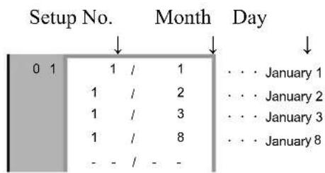
• Using Keys
Using the "3," "6," "8," and "11" keys, move the cursor to the desired position and change the setup by pushing "UP" and "DOWN" keys.
- Using a mouse
Click on the position to be set up. Each click changes between ON and OFF. Left- or right-click on the positions for setup. The left click increases the number. The right click decreases the number.
Note
- When the weekly setup and holiday setup are overlapped, the Holiday Setup is given priority.
| Items | Settings |
| MENU | Returns to the Main Menu Screen |
Motion Setup
How to conduct Motion Detect Setup.
- Select "ENTER" button of the intended camera.

⇒ The Motion Setup Screen will be displayed.

* The background display is live feed from the selected camera.
* The screen is divided into a grid of 30×24. For each of 28×22 areas but the circumference, enable/disable status and sensitivity of motion detection can be set up.
* When movement is detected in an area wherein Motion Setup in set in ON, the area in which such movement has been detected is colored in orange.
- Setting up motion detection areas
- Using Keys
1) Using the “3,” “6,” “8,” and “11” keys, move the cursor (pink color) to the intended area for motion setup and change between Motion Detect ON and OFF with the “7” key. The area set in ON turns to green color
Motion Detect ON: Green color
Motion Detect OFF: No color
2) By pushing the "UP" and "DOWN" keys, the sensitivity of the selected area is set up.
SENSE LEVEL: 1\~5 (SENSE LEVEL 1 is the setup for highest sensitivity)
3) Pushing the "MENU" ends the setup and returns to the Motion Screen Selection Screen
- Using a mouse
1) Click on the intended area for motion setup. Each click changes between ON and OFF. Motion Detect ON: Green color Motion Detect OFF: No color
2) Right click of the mouse shows the menu for sensitivity setup of the selected area.
| ENTER |
| BACK |
| CANCEL |
| SENSE 1 |
| SENSE2 |
| SENSE3 |
| SENSE4 |
| SENSE5 |
. . . Setup finished
- - - Returns to the Motion Setup Screen
- - - Returns to the Motion Screen Selection Screen
··· Sensitivity 1\~5
3) Click on the "ENTER" button. When the setup has been changed, the save menu is displayed.
| OK |
| BACK |
| CANCEL |
• • • Saves the setup and returns to the Recording Setup Menu
- · · Returns to the Motion Screen Selection Screen
··· Cancels the setup and returns to the Recording Setup Menu
4) Click on the "OK" button and return to the Recording Setup Menu
Caution
- Some monitors show the displayed areas smaller than the actual video display. In such a case, some of the areas might not be properly displayed.
- It is advisable to check the operation for proper detection performance before using the Motion Detect Function.
Screen Display Setup
Below shows how to set up screen display.
| DISPLAY SETUP | |
| OSD SETUP | ENTER |
| MONITOR OUTPUT | SETUP |
| AUTO SEQUENCE | SETUP(MON1) |
| AUTO SEQUENCE | SETUP(MON2) |
| CAMERA NAME SETUP | ENTER |
| MONITOR1 INIT. | MODE |
| MONITOR2 INIT. | MODE |
| FULL SCREEN VIEW | SETUP 1 |
| FULL SCREEN VIEW | SETUP 2 |
| FULL SCREEN VIEW | TIME |
| MENU | |
| Items | Settings |
| OSD SETUP | Displays the OSD Display Setup Screen (→P.70) |
| MONITOR OUTPUT SETUP | Displays the Monitor Output Setup Screen (→P.72) |
| AUTO SEQUENCE (MON1) SETUP | Displays the Automatic Sequence Setup Screen. (→P.73) |
| AUTO SEQUENCE (MON2) SETUP | |
| CAMERA NAME SETUP | Displays the Camera Name Setup Screen (→P.74) |
| MONITOR 1 INIT. MODE | Sets up the initial Screen display mode when Monitor Startup. |
| MONITOR 2 INIT. MODE | POS1~16, 4SEG A~D,9SEG A, B and 16SEG |
| FULL SCREEN VIEW SETUP | Sets up Screen Display conditions upon event occurrence.ALARM: Only AlarmMOTION: Only MotionALL: Alarm and MotionNO: No sequence |
| FULL SCREEN VIEW PRIORITY | Sets up the event to be displayed by priority upon event occurrence.FIRST: Gives priority to the first event occurrenceLAST: Gives priority to the last event occurrence |
| FULL SCREEN VIEW TIME | Sets up the time for displaying upon event occurrence. The 0 sec setup does not display any image.Setup range: 0~9, 10, 20, 30, 40, 50, 60, 70, 80, 90, 100, 110, and 120sec, INFINITY |
| MENU | Returns to the Main Menu Screen |
Below are instructions on how to set up the screen display using playback or recording.
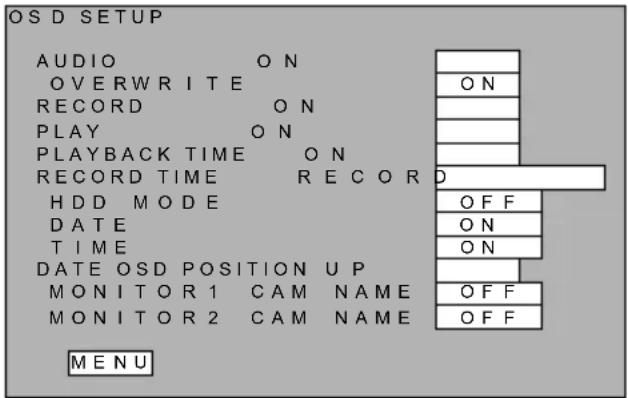
| Items | Settings |
| AUDIO | Enable or disable the display of sound recording status (“♪”) during recordingON: Enables displayOFF: Disables display |
| OVERWRITE | Enable or disable the display of overwrite setup (⇒,_) during recordingON: Enables displayOFF: Disables display |
| RECORD | Enable or disable the display of recording status (●) during recordingON: Enables displayOFF: Disables display |
| PLAY | Enable or disable the display of playback speed during playbackON: Enables displayOFF: Disables display |
| PLAYBACK TIME | Enable or disable the display of playback timeON: Enables display at the display position of current timeALL: Enables display for each playback screen (In the 16-split screen mode, the play time is displayed at the same position in case of selecting ONLY.)OFF: Disables display |
| RECORD TIME | Enable or disable the display of recording timeRECORD: Enables display of recording timeREMAIN: Enables display of remaining timeOFF: Disables display |
| HDD MODE | In case of MIRROR mode, , the “MIRROR” is displayed.ON: Enables displayOFF: Disables display |
| DATE | Enable or disable the display of current dateON: Enables displayOFF: Disables display |
| TIME | Enable or disable the display of current timeON: Enables displayOFF: Disables display |
DATE OSD POSITION Sets up the display position of current date and time UP : Center top
| Items | Settings |
| DOWN : Center bottomLEFT UP : Left topLEFT DOWN : Left bottomRIGHT UP : Right topRIGHT DOWN : Right bottom | |
| MONITOR1 CAM NAME | Enable or disable the display of camera namesOFF : Disables display |
| MONITOR2 CAM NAME | NAME : Enables display of camera namesNUM : Enables display of camera No. |
| MENU Returns to the Display Setup Screen | |
Monitor Output Setup
This is to set up whether to display the live feeds from each camera on Monitor 1 or 2. During playback, all cameras' recorded video is displayed regardless of the setup entered herein.

| Items | Settings |
| MONITOR1 Enable or disable the display of live feeds. | |
| MONITOR2 | ON: Enables displayOFF: Disables display |
| MENU | Returns to the Display Setup Screen |
Automatic Sequence Setup
This menu sets up the screen display operation when pushing the “SEQ DISP” key. (In case the sequence setup is changed during automatic sequence in operation, the change setup is activated after the current sequence operation is finished.)

After the setup “display time” is over, the display is automatically switched in the order listed in the “display screen” Setup for 22 steps is possible.
| Items | Settings |
| Display screen Sets up the display screen for each stepSetup range :POS 1~16 / 4 SEG A~D / 9SEG A, B / 16SEG | |
| Display time | Sets up the display time for each step.Setup range : 0~60 sec |
| MENU | Returns to the Display Setup Screen |
Caution
• The display time for STEP1 cannot be set in 0 second.
Camera Name Setup
This is to set up then names of each camera.

- Using the "3" and "11" keys, move the cursor to the "ENTER" button, and push the "7" key. Or, click on the "ENTER" button with a mouse.
⇒ The Camera Name Entry Screen will be displayed.

- Using the “3,” “6,” “8,” and “11” keys, move the cursor to the letters to be entered and select by pushing the “7” key.
When using a mouse, click on the letters.
* Selecting the "BS" button deletes one letter.
* Maximum number of entry letters: 15 letters for each camera
⇒ The entered letters are displayed on the screen.
- After finishing the name entry, use the "3," "6," "8," and "11" keys to move the cursor to the "OK" button, and select it with the "7" key. When using a mouse, click on the "OK" button.
⇒ The screen display returns to the Camera Name Selection Screen.
* Selecting the "CANCEL" button, the setup is cancelled.
Network Setup
This sets up parameters necessary for LAN connection.

| Items | Settings |
| IP ADDRESS | Sets up IP addressSetup range: 0~255, 4 digits |
| SUBNET MASK | Sets up subnet maskSetup range: 0~255, 4 digits |
| DEFAULT GATEWAY | Sets up default gatewaySetup range: 0~255, 4 digits |
| PRIMARY DNS SERVER | Sets up primary DNS serverSetup range: 0~255, 4 digits |
| SECONDARY DNS SERVER | Sets up secondary DNS serverSetup range: 0~255, 4 digits |
| WEB PORT NUMBER | Sets up port number of WEB serverSetup range: GENERIC, 1024~65535GENERIC is set in No.80 |
| LIVE DELIVERY IMAGE | Sets up the image quality of live deliverySetup range: IMAGE 1~4* See P.62“Image Quality Setup” for more detail |
| TRANSFER RATE | Sets up transfer rateSetup range: 32, 64, 128, 256, 512Kbps,1 ,2, and 4Mbps, UNLIMITED |
IMPORTANT!
- In order to enable the changed network setup, conduct the following operations after exiting the Menu.
- Turn "OFF" the main power switch on the equipment back panel.
- Wait for about 5 seconds and start up again. (See P.18 "Starting Up.")
E-mail Setup
This is to establish the e-mail setting to be conducted in the event of an alarm input or malfunction.

| Items | Settings |
| SOURCE ADDRESS | Sets up the address of this equipment (→P.72) |
| DESTINATION ADR1 | Displays the Entry Screen for Destination Address 1 |
| DESTINATION ADR2 | Displays the Entry Screen for Destination Address 2 |
| DESTINATION ADR3 | Displays the Entry Screen for Destination Address 3 |
| DESTINATION ADR4 | Displays the Entry Screen for Destination Address 4 |
| SMTP SERVER DOMAIN | Set up the domain address of SMTP server |
| POP AUTHENTICATION | Sets up whether to conduct POP3 certification when sending mailYES: conducts certificationNO: not to conduct certification |
| ENCRYPTION | Sets up whether to encrypt the User Name and Password for POP3 certificationYES: encryptNO: not to encrypt |
| USER NAME | Displays the Entry Screen for User Name for POP3 certification |
| PASSWORD | Displays the Entry Screen for Password for POP3 certification |
| POP3 SERVER DOMAIN | Sets up the domain address of POP3 server |
| SUBMIT SETUP | Displays the Sending Conditions Setup Screen (→P.78) |
| TEST SUBMIT | Conducts test sending mail containing the title “EMR-16” and main text “TEST” to the designated destination addresses. |
| MENU | Returns to the Main Menu |
[Setup Procedure of Address, User Name and Password]
Screen display example) Source Address

- Using the “3,” “6,” “8,” and “11” keys, move the cursor to the letters to be entered and select by pushing the “7” key.
When using a mouse, click on the letters.
* Maximum number of entry letters
USER NAME or PASSWORD: 23 letters, Others: 46 letters
* Selecting the "BS" button deletes one letter.
⇒ The entered letters are displayed on the screen.
- After finishing the entry, use the "3," "6," "8," and "11" keys to move the cursor to the "OK" button, and select it with the "7" key. When using a mouse, click on the "OK" button.
⇒ The display returns to the E-mail Setup Screen.
Selecting the "CANCEL" tab disables the setting.
Sending Condition Setup
This is to set up whether to send e-mail in the event of an internal alarm, recording start due to alarm input or motion detection.

| Items | Settings |
| SYSTEM ALARM | Sets up whether to send e-mail upon occurrence of internal alarmON: To sendOFF: Not to send |
| ALARM1~16 | Sets up whether to send e-mail upon recording start due to alarm inputON: To sendOFF: Not to send |
| MENU | Returns to the E-MAIL setup Screen |
System Setup
| SYSTEM SETUP | |
| HD REMAINING TIME | 0 HOUR |
| BUZZER | EFFECT |
| ALARM OUTPUT | |
| DURING ALARM REC | ON |
| INTERNAL ALARM | OFF |
| LEVEL WARNING | OFF |
| ALARM OUTPUT TIME | DURING REC |
| CAMERA SETUP | ENTER |
| USER SETTING | ENTER |
| PLAY DISK | ALL |
| LAYOUT MODE | INACTIVE |
| MENU | |
| Items | Settings | |
| HD REMAINING TIME Sets | the remaining recording time under which the “HDD” indicator lights up in orange in case the “OVERWRITE” setup under “Recording Setup” is set in “NO”Setup range: 0~999 (hours) | |
| BUZZER | Sets up whether to sound the buzzer (in the cases of alarm events, motion detection, video loss of the recording channel, internal defects, etc) EFFECT : enabledNO EFFECT : disabled | |
| ALARM OUTPUT Sets up alarm output | ||
| DURING ALARM REC | Output during alarm recordingON : EnabledOFF : Disabled | |
| INTERNAL ALARM Output | put upon occurrence of internal alarm (video loss, disk defect, etc)ON : EnabledOFF : Disabled | |
| LEVEL WARNING | Sets up the output conditions in case of remaining time warning and disc full situationON : EnabledOFF : Disabled | |
| ALARM OUTPUT TIME Sets up alarm output timeDURING ALARM REC : alarm output enabled while alarm continues1 SEC : alarm output enabled for 1 second after an occurrence of alarm | ||
| CONTROL CAMERA | Displays the Control Camera Setup Screen (→P.80) | |
| USER SETTING | Displays the User Setup Screen (→P.81) | |
| PLAY DISK Sets up the active disk in MIRROR mode.ALL:ALL Disk(LONG format only, No mirror operation)DISK A:Disk A side(MIRROR format Disk A)DISK B:Disk B side(MIRROR format Disk B)In the explanation of P. 90, disks in the left side of ‘⇔’ such as HDD-A,HDD-C and HDD-E are included in DISK A side. | ||
| LAYOUT MODE Set ACTIVE/INACTIVE of layout setting.ACTIVE: EnabledINACTIVE: Disabled | ||
| MENU | Returns to Main Menu screen | |
Control Camera Setup Screen
This is to select the camera to be controlled by RS-485.
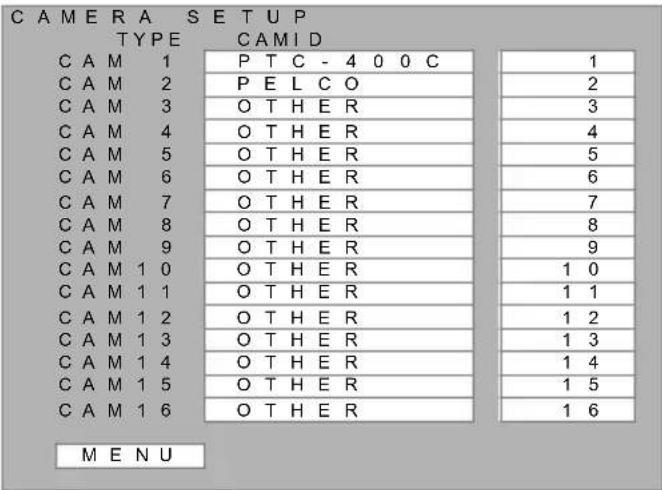
Cameras shown below can be controlled:
Regarding TYPE
PTZ Camera: ELMO PTC-400C, Pelco-D
Other cameras: Other than PTZ cameras (fixed)
Regarding CAMID
Sets up the ID of PTZ cameras
User Setup
From this screen, User Setup and registration can be conducted. Administrator user cannot conduct this Setup.

| Items | Setup value | Settings |
| ADMIN | Under 20 letters | Sets up the ADMIN NameThe ADMIN user cannot change SYSTEM SETUP to DISABLE. |
| ADMIN PASS | Under 20 letters | Displays the Password Setup Entry Screen |
| ADMIN CTRL | Displays the User Control Setup Screen | |
| USER | Under 20 letters | |
| USER PASS | Under 20 letters | Displays the Password Setup Entry Screen |
| USER CTRL | Displays the User Control Setup Screen | |
| MENU | Returns to the System Setup sreen |
- Using the “3,” “6,” “8,” and “11” keys, move the cursor to the User Name to be changed (or newly entered) and select by pushing the “7” key. Or, click on the User Name to be changed. The User Name Entry Screen will be displayed.

- Enter the User Name. Using the "3," "6," "8," and "11" keys, move the cursor to the letters to be entered and select by pushing the "7" key.
When using a mouse, click on the letters.
→ The entered letters are displayed on the screen.
- Use the "3," "6," "8," and "11" keys to move the cursor to the "OK" button, and select it with the "7" key. When using a mouse, click on the "OK" button.
⇒ The screen returns to the User Setup Screen. In case a new User Name has been set up, the screen displays the Password Entry Screen. Proceed with password setup.
- Using the “3,” “6,” “8,” and “11” keys, move the cursor to the “ENTER” button of the password to be changed and select by pushing the “7” key. Or, click on the “ENTER” button. The Password Entry Screen will be displayed.

- Enter the password. Using the "3," "6," "8," and "11" keys, move the cursor to the letters to be entered and select by pushing the "7" key.
When using a mouse, click on the letters.
⇒ The entered password is displayed with asterisk “*.”
- Use the "3," "6," "8," and "11" keys to move the cursor to the "OK" button, and select it with the "7" key. When using a mouse, click on the "OK" button.
⇒ The screen returns to the User Setup Screen.
Enable or disable the user's permission to change the setup.
The default setup for ADMIN level is "ENABLE" and for USER level is "DISABLE."
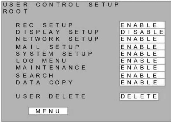
| Items | Setup value | Settings |
| REC SETUP | ENABLE/DISABLE | Recording Setup |
| DISPLAY SETUP | ENABLE/DISABLE | Display Setup |
| NETWORK SETUP | ENABLE/DISABLE | Network Setup |
| MAIL SETUP | ENABLE/DISABLE | E-mail Setup |
| SYSTEM SETUP | ENABLE/DISABLE | System Setup (User Name cannot be set up) |
| LOG MENU | ENABLE/DISABLE | Log Browsing (Parameters are damaged) |
| MAINTENANCE | ENABLE/DISABLE | Maintenance Setup |
| SEARCH | ENABLE/DISABLE | Search |
| DATA COPY | ENABLE/DISABLE | Data copy |
| USER DELETE DELETE | DELETE | * The top user on ADMIN level cannot be deleted. |
Log Display
Log Display has the following items:
• REC LOG: Log of dates and times when recording started and ended
• ERROR LOG: Log of times and types of error occurrence
- STARTUP LOG: Log of times when the equipment was turned on or restored from power outage
- USER LOG: Log of USER operations described by user names and menu names
| LOG VIEWER | |
| REC LOG | ENTER |
| ERROR LOG | ENTER |
| STARTUP LOG | ENTER |
| USER LOG | ENTER |
| MENU | |
Recording Log
This displays the dates and times of recording start and end from the latest log entry. This log records up to 1000 entries after which point the oldest ones are deleted in order.
| R E C L O G | |||||||||||
| D A T E / T I M E | C A M S T A T U S | ||||||||||
| 0 | 5 / | 2 | / | 1 | 5 | 1 | 2 : 0 | 0 : 0 | 0 | 9 | M O T I O N R E C E N D |
| 0 | 5 / | 2 | / | 1 | 4 | 1 | 2 : 0 | 0 : 0 | 0 | 9 | M O T I O N R E C S T A R T |
| 0 | 5 / | 2 | / | 1 | 3 | 1 | 2 : 0 | 0 : 0 | 0 | 5 | T I M E R R E C E N D |
| 0 | 5 / | 2 | / | 1 | 2 | 1 | 2 : 0 | 0 : 0 | 0 | 5 | T I M E R R E C S T A R T |
| 0 | 5 / | 2 | / | 1 | 1 | 1 | 2 : 0 | 0 : 0 | 0 | 1 | A L A R M R E C S T A R T |
| 0 | 5 / | 2 | / | 1 | 0 | 1 | 2 : 0 | 0 : 0 | 0 | H A N D R E C E N D | |
| 0 | 5 / | 2 | / | 9 | 9 : 0 | 5 : 0 | 0 | H A N D R E C S T A R T | |||
| 0 | 5 / | 2 | / | 8 | 7 : 0 | 0 : 0 | 0 | 1 | A L A R M R E C E N D | ||
| M E N U | |||||||||||
Scroll on the screen using the "3" and "11" keys or click and right click. To finish the screen, push either the "7" or "11" key.
20 log entries are displayed at maximum on the screen, and below the oldest log is indicated by “—.”
| Items | Setting value | Indications |
| DATE TIME | Displays the date and time the event occurred | |
| CAM | Displays the Camera No. wherein the event occurred.The Camera No. is not displayed for Manual recording start/end and Automatic recording start/end. | |
| STATUS | Displays types of the logged eventsMOTION REC START: Motion recording startMOTION REC END: Motion recording endALARM REC START: Alarm recording startALARM REC END: Alarm recording endCONTINUE REC START: Timer recording startCONTINUE REC END: Timer recording endMANUAL REC START: Manual recording startMANUAL REC END: Manual recording end | |
| MENU | — | Returns to the Log Selection Screen |
Error Log
This displays the dates and times when errors occurred with the latest log entry at the top. This log records up to 100 entries after which point the oldest ones are deleted in order.

Scroll on the screen using the "3" and "11" keys or click and right click. To finish the screen, push "7" key.
20 log entries are displayed at maximum on the screen, and below the oldest log is indicated by “—.”
| Items | Setting value | Indications |
| DATE TIME | Displays the date and time the event occurred. | |
| CAM | Displays the Camera No. wherein the event occurred.In case of HDD ERROR, the number of the troubled HDD is shown.The number is related to the HDD name in P.17.1:HDD-A MASTER 2:HDD-A SLAVE3:HDD-B MASTER 4:HDD-B SLAVE5:HDD-C MASTER0 6:HDD-C MASTER17:HDD-C MASTER2 8:HDD-C MASTER39:HDD-D MASTER0 10:HDD-D MASTER11:HDD-D MASTER2 12:HDD-D MASTER313:HDD-E MASTER0 14:HDD-E MASTER115:HDD-E MASTER2 16:HDD-E MASTER317:HDD-F MASTER0 18:HDD-F MASTER119:HDD-F MASTER2 20:HDD-F MASTER3 | |
| STATUS | Displays types of the logged events.VIDEO LOSS: Occurrence of video lossVIDEO INPUT: Video input (The image input is regained from video loss.):VIDEO INVALID: Video invalid (The video input was disabled.)REST WARNING START: Rest warning start (The remaining capacity of HDD is less than the warning setting.)REST WARNING END: Rest warning end (As the remaining capacity of HDD is more than the warning setting, the warning is cancelled.)DISK FULL: Disk full (The disk is full.)DISK FULL CANCEL: Cancels the disk full error.HDD ERROR: Occurrence of hard disk error | |
| MENU | — | Returns to the Log Selection Screen. |
Startup Log
This log records the dates and times when the power was turned or the equipment was restored from power outage, and displays the latest log entry at the top. This log records up to 100 entries after which point the oldest ones are deleted in order.

Scroll on the screen using the "3" and "11" keys or click and right click. To finish the screen, push "7" key.
20 log entries are displayed at maximum on the screen, and below the oldest log is indicated by “—.”
| Items | Setting value | Indications |
| DATE TIME | — | Displays the date and time the event occurred. |
| STATUS | Main power ON / | Displays the type of startup.MAIN POWER ON: Main power was turned ON. |
| MENU | — | Returns to the Log Selection Screen. |
User Log
This log records the operations by USERS and displays the latest record at the top. This log records up to 200 entries after which point the oldest ones are deleted in order.
| USER LOG | |||||
| OPERATION | DATE/TIME | DETAIL | USER | NAME | |
| 05/ | 2/10 | 9:03:15 | MAIN MENU | ELMO | |
| 05/ | 2/10 | 9:03:10 | REC SETUP | ELMO | |
| 05/ | 2/10 | 9:03:03 | REC CONDITION | ELMO | |
| 05/ | 2/10 | 9:00:20 | *SCHEDULE SETUP | ELMO | |
| 05/ | 2/10 | 9:00:10 | REC SETUP | ELMO | |
| 05/ | 2/10 | 9:00:00 | MAIN MENE | ELMO | |
| MENU | |||||
Scroll on the screen using the "3" and "11" keys or click and right click. To finish the screen, push "7" key.
20 log entries are displayed at maximum on the screen, and below the oldest log is indicated by “—.”
| Items | Setting value | Indications |
| DATE TIME | — | Displays the date and time the event occurred |
| DETAIL | — | Displays the Menu namesCAM 1 MOTION~CAM16 MOTION:Motion setting screen (each camera)CAM 1 CAM NAME~CAM16 CAM NAME:Camera name setting screen (each camera)LOG_OUT: Logout from the menuMAIN MENU: Main menuREC SETUP: Recording setting screenREC CONDITION: Recording condition setting screenSCHEDULE SETUP: recording schedule setting screenCONCURRENT REC: Concurrent recording camera setting screenHOLIDAY SETUP: Holiday setting screenMOTION SETUP: Motion screen selection screenDISPLAY SETUP: Screen setting screenOSD SETUP: OSD setting screenMONITOR OUTPUT: Monitor output setting screenAUTO SEQ MONI 1: Auto sequence setting (Monitor-1) screenAUTO SEQ MONI 2: Auto sequence setting (Monitor-2) screenCAM NAME SETUP: Camera name setting screenNETWORK SETUP: Network setting screenMAIL SETUP: Mail setting screenSOURCE ADDRESS: Sender setting input screenDESTINATE ADDR1: Destination address-1 setting input screenDESTINATE ADDR2: Destination address-2 setting input screenDESTINATE ADDR3: Destination address-3 setting input screenDESTINATE ADDR4: Destination address-4 setting input screenPOP3_USER NAME: User setting input screenPOP3_PASSWORD: Password setting input screenSMTP SERVER: SMTP server setting input screen |
| Items | Setting | value Indications |
| POP3 SERVER: POP3 server setting input screenSUBMIT SETUP: Sending condition setting screenSYSTEM SETUP: System setting screenCAMERA SETUP: Control camera setting screenUSER SETUP: User setting screenUSER ENTRY: User setting input screenPASSWORD: Password setting input screenUSER CTRL SET: User control setting screenLOG VIEWER: Log menu screenREC LOG: Log screen (recording)ERROR LOG: Log screen (error)START UP LOG: Log screen (start)USER LOG: Log screen (operation)MAINTENANCE: Maintenance screenHDD RESET: Harddisk initialization screenRECORD SEARCH: Search screenDATA COPY: Data copy screenNTP SERVER: NTP server setting input screenLOG_IN: Login screenAUTO SEQ MONI: Auto sequence setting screen (for WEB)HDD RESET EXEC: Initialize harddiskSETUP RESET: Initialize settingEXPORT SETTING: Export settingIMPORT SETTING: Import setting | ||
| USER NAME | — | Displays the User Name who conducted operation |
| MENU | — | Returns to the Log Selection Screen |
Note) * is displayed when the Setup has been changed.
Equipment Maintenance
This setup conducts the resetting of log records or formatting of hard disks.
| MAINTENANCE | |||
| TIME SETUP 2005Y 1M 1D 0H 0M 0S | |||
| HDD RESET ENTER | |||
| SETUP RESET ENTER | |||
| LOG RESET ENTER | |||
| EXPORT SETTING ENTER | |||
| IMPORT SETTING ENTER | |||
| DAYLIGHT SAVINGS TIME ON | |||
| BIGIN APR 1ST SUN 2:00 | |||
| END OCT LAST SUN 2:00 | |||
| NTP SERVER DOMAIN ntp.e1 ENTER | |||
| TIME ZONE +09:00 | |||
| MENU |
| Items | Settings |
| TIME SETUP Sets up the current timeIt is to be set up in case the power has been turned off for a long period of time and the data and time have been undisplayed. | |
| HDD RESET Formats hard disks. The setup setting and log record are kept. Displays the Hard Disc Format screen.See “How to Format Hard Disks” (→P.89) for more detailed instruction. | |
| SETUP RESET Resets the saved Menu setups | |
| LOG RESET Resets the log | |
| EXPORT SETTING | Outputs and writes the setup settings onto the connected media.In case no media is connected or error occurs during writing, an error message is displayed. |
| IMPORT SETTING When reading the setup settings from the file output in EXTERNAL OUTPUT operation and afterward edited by PC, a reading error occurs.In case no media is connected or error occurs during reading, an error message is displayed. | |
| DAYLIGHT SAVINGS TIME | Sets up whether to apply summer time. (This sets the time an hour earlier than usual.)ON: EnabledOFF: Disabled |
| BEGIN Sets up the starting time for summer time | |
| END | Sets up the ending time for summer time |
| NTP SERVER DOMAIN | Moves to NTP server domain name input screen. |
| TIME ZONE Sets the time zone at a 15-minute interval. (-12:00~+13:00) | |
| MENU Returns to the Main Menu screen. | |
Writing Method
- When selecting "SETUP RESET," "LOG RESET," "EXPORT SETTING," or "IMPORT SETTING," the confirmation screen for executing the selected maintenance is displayed.

- Use the "6" and "8" keys to move the cursor to the "YES" button, and select it with the "7" key. When using a mouse, click on the "YES" button. ⇒ The selected maintenance operation is executed. * For cancelling the selected maintenance, select "NO."
Caution
- When writing the setup, it is stored in the file name "PARAM16.DAT" in the root directory of USB media.
How to Format Hard Disks
Through the setup of disk mode, hard disks can be formatted.
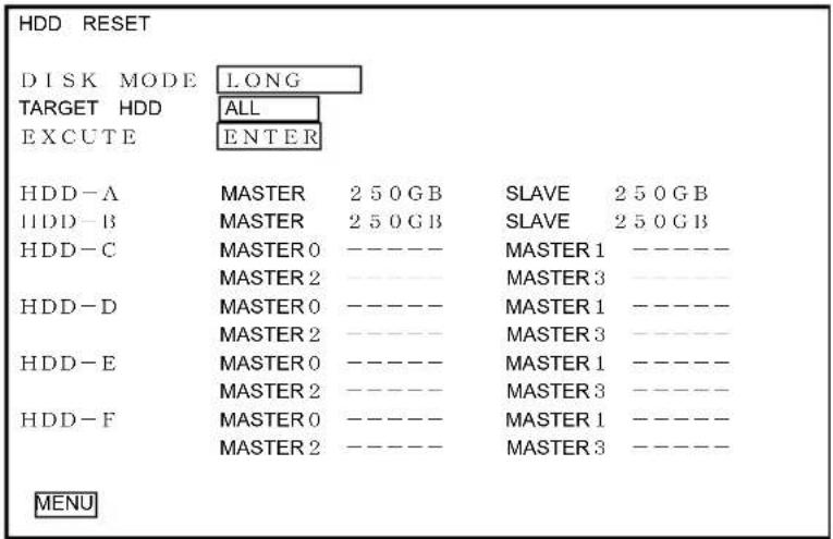
| Items | Settings | |
| DISK MODE | LONG | Formats hard disks in Extended (Long Time) recording mode |
| MIRROR1 | Formats hard disks in mirroring recording mode where it is conducted first on the installed hard disks and the expanded disks. | |
| MIRROR 2 | Formats hard disks in mirroring recording mode to be conducted only on the expanded hard disks. | |
| TARGET HDD | ALL | Initializes all connected hard disks. |
| NEW HDD ONLY | Initializes only replaced or added unused hard disks. | |
| EXCUTE | ENTER | Executes hard disc formatting. |
| MENU | Returns to the Maintenance screen. |
Below is the data writing order in each disk mode in the hard disk setup:
Extended (Long) recording
HDD-A → HDD-B → HDD-C → HDD-D → HDD-E → HDD-F →
HDD-A → · · ·
Mirroring recording 1 (Mirroring for Installed HDD, Expanded HDD Unit 1 and Expanded HDD Unit 2)
HDD-A ⇔ HDD-B → HDD-C ⇔ HDD-D → HDD-E ⇔ HDD-F →
HDD-A ⇔ HDD-B → · · ·
Mirroring recording 2 (Mirroring for Expanded HDD Unit 1 and Expanded HDD Unit 2)
HDD-C ⇔ HDD-D → HDD-E ⇔ HDD-F → HDD-C ⇔ HDD-D →
HDD-E ⇔ HDD-F → · · ·
* In case the hard disk capacity differs in mirroring recording mode, the recording stops (or moves on to the next disks) when the hard disk with larger capacity is full.
* In case a partner disk is not connected (in such a case where mirroring recording is conducted while only one unit of Installed HDD is installed), the recording is conducted using only the connected hard disk drives.
Operation Under Error Status
Hard Disk Error
In case an error occurs in hard disks while recording including pre-alarm, the recording is continued using other hard disks regardless of the recording mode. In such a case, the equipment alarm indicator flickers, buzzer sounds (according to setup), alarm is output (according to setup) and error log conducts recording.
In case an error occurs in all hard disks during startup / recording or error occurs in any of the hard disks during disk formatting, a message below is displayed.
HDD ERROR
PLEASE PRESS MENU KEY AND HDD RESET
Turn off the power by pushing the “POWER” key and push the “POWER” key again to restart the equipment.
Video Loss
Under all conditions except for standby mode, video loss is being monitored. When detecting video loss, the equipment alarm indicator lights up (in red color), buzzer sounds (according to setup), alarm is output (according to setup) and error log conducts recording.
The target of video loss detection is cameras being turned “Recording” in “Recording Setup” mode.
Output under Error Status
Alarm Output
| Alarm output setup | Alarm output time setup | Recording on alarm input and motion | Hard disk error Video loss | Remaining time runs short of setup time |
| Alarm recording | During alarm recording | Output during recording | Not influenced Not influenced | |
| 1 second Output | for 1 second after recording start | Not influenced Not influenced | ||
| Internal alarm | — | Not influenced | Output until error is restored | Not influenced |
| Remaining time warning | — Not influenced | Not influenced | Output while running short | |
Buzzer
| Buzzer setup | Recording on alarm input and motion | Hard disk errorVideo loss | Remaining time runsshort of setup time |
| ON Output during recordingPress “STOP” key to stop the buzzer. | Output until error is restoredPress “STOP” key to stop the buzzer. | Not output | |
| OFF Not output | Not output Not output | ||
| Sending conditions | Recording on alarm input | Recording on motion | Hard disk error Video loss | Remaining time runs short of setup time |
| Internal alarm | Not to be sent Not to be sent To be sent Not to be sent | |||
| ALARM To be sent Not to be sent Not to be sent | Not to be sent | |||
Troubleshooting
When encountering the situations below, follow the instructions and try the troubleshooting measures provided.
In case doing so does not solve the problem, contact the dealer where you purchased the DVR.
| Phenomenon Possible Cause Measures to be taken | ||
| No screen image | Power is not turned on. | Start up the equipment. (→P.18) |
| Power plug is not inserted into the outlet properly. | After turning the main power off, insert the power plug all the way, and start up the equipment. In case the plug is soiled, clean up. | |
| Video cables are not properly connected. | Check the connection of video cables and connect them properly. (→P.13~P.17) | |
| Monitor Output Setup is set in “Non-Display.” | Set the Monitor Output Setup in “Display.ON” (→P.72) | |
| Cannot stop recording | Check the schedule setup (→P.63) and rectify accordingly. | |
| Cannot conduct Automatic Recording (CONTINUE, alarm, or motion) | Not in Automatic recording mode | Set in Automatic recording mode (→P.26) |
| The setup is not appropriate. | Check the schedule setup (→P.63) and rectify accordingly. | |
| The time setup is not correct. Set up the current date and time accurately (→P.88) | ||
| Cannot conduct alarm recording | The cord for alarm input is not connected properly. | Check the connection of alarm input cord and connect properly. (→P.14) |
| Cannot conduct motion recording | The motion recording in not enabled or not set up properly. | Set up for appropriate detection areas and sensitivity levels (→P.67) |
| Unable to end the recording setup | A combination of recording rates that cannot allocate the same field | Set TOTAL REC RATE to 118 or less. (→P.61) |
| Sound is not recorded. | The recording setup for “AUDIO” is set in “NO.” | Set the recording setup for “AUDIO” in “YES.” (→P.59) |
| The cables for sound are not connected properly | Check the connection of sound cables and connect properly. (→P.16) | |
| Cannot conduct search and playback | The hard disks have been formatted or not no recorded data is not them | After recording, conduct search or playback (→P.25, 34) |
| No recorded data is available on the designated disk. | Change the playback disk. (→P.88) | |
| No playback video. | Check the LAYOUT setup. (→P.31) | |
| No OSD display. | The OSD Display Setup is in “OFF.” | Check the OSD display setup and set it in “YES.” (→P.70) |
| The current time displayed on the screen is not correct. | The time has not been adjusted or the main power has not been turned on over a long period of time. | In case the main power is not turned on for over 30 days, the time data is lost. The error of the installed clock is within ±30 seconds per month and the precision is 5±5ppm. Adjust the clock as needed. (→P.88) |
| The alarm indicator keeps lighting up and does not go off. | Error such as video loss has occurred during recording. (→P.Error! Bookmark not defined.) | Format the hard disc. (→P89) |
| “HDD ERROR” message is displayed on the screen. | The format information on the hard disk has been damaged. | Restart the hard disk and format it. (→P89) |
| Error occurred to the hard disk Contact the dealer where you purchased. | ||
Warranty and Services
Warranty
The warranty certificate is presented from the dealer. Be sure to check the “name of dealer, purchase date” etc on the certificate, read the warranty descriptions carefully and keep it safely. The duration of warranty of this equipment is 2 years from the date of purchase. The warranty for hard discs is for 1 year from the date of purchase.
When requesting repair during warranty period
Contact the dealer of your purchase. The dealer is in charge of repair pursuant to the descriptions on the certificate. The warranty certificate needs to be presented upon requesting repair. The information necessary on such an occasion is as follows: Address, Name, Telephone Number Date of Purchase (refer to the certificate) Descriptions of malfunction or error
Repair after expiration of warranty period
In case repair is necessary after the expiration of the warranty period, first contact the dealer of your purchase.
Inquiry
Contact the dealer of your purchase for any inquiry regarding repair during the warranty period or after-sales service.
Repair Parts
We keep the repair parts (parts necessary to maintain the desired functions) for this product until 6 years after the termination of manufacture. This parts storage period also represents the period wherein repair service can be offered.
Specifications
- Basic Specifications
| Items | Description | Remarks |
| Power | 120VAC, 60Hz | |
| Power consumption 70W HDD×4 | ||
| External dimensions W: 42 | 0.5, H :88, D: 368 (mm) | |
| Weight Approx. 8.2 kg HDD×4 | ||
| Recommended Installation | Indoors, on a flat area (horizontally) | |
| Service temperature and humidity | 5°C~40°C, 30%~80% | Non-condensing |
| Accessories Instruction Manual, AC cable, Warranty, HDD Instruction | ||
- Input / Output Specifications
| Items | Description | Remarks | |
| Video | Signal method | NTSC Compliant | |
| Video input | 16 inputs (BNC), VBS, 1.0V (p-p)75Ω auto termination | Hi-Z reception when loop-out is connected | |
| Video output | 2 inputs (BNC), VBS, 1.0V (p-p)75Ω | ||
| Video loop-out | 16 outputs (BNC) | Loop through of video input | |
| Sound | Sound input | 1 input (RCA pin), 0dBV (316mV)Over 10kΩ unbalanced | |
| Sound output | 1 input (RCA pin), 0dBV (316mV)600Ω unbalanced | ||
| Alarm | Input | 16 inputs (Terminal block) for each cameraNo-voltage make contactOr TTL level negative logic pulse | |
| Output | 1 input (Terminal block), Open collector | ||
| Network | 1 port (RJ-45) | 100BASE-TXIEEE802.3 compliant | |
| RS-485 | 1ch (Terminal block 6P)Half duplex asynchronous method9600bps | PTZ camera control output | |
| USB | 2ch USB1.1 compliant (A connector) | For copy and for mouse, one for each | |
| Expansion hard disk terminals | Disk terminals | e-SATA connector2 ports | |
| Control terminals | RJ11 4-pole 4-core connector2 ports RS232C level |
- Function Specifications
| Items | Description | Remarks | |
| Recording | Image processing method | Encoding method: Motion JPEGInput: 13.5MHz 4:2:2 format 8 bitPixels: 720×240 pix/field | |
| Sound processing method | Encoding method: PCM digitalInput: 16kHz 8bit monaural | ||
| Recording medium 3.5" HDD (IDE) mounted4 units as normal equipment | Disk structure decided on formatting(Extended or mirroring)when expansion unit is not used | ||
| Manual recording setup | Recording interval: 10 steps(60, 30, 15, 10, 7.5, 5, 4, 3, 2,1PPS)Recording image quality: 4 steps (64, 48, 32, 16 KB)Sound recording: enabled or disabled | The recording interval can be set up for each camera(Limiting conditions depending on the number of cameras)The recording image quality can be set up for each camera | |
| Recording | Automatic recording setup | Sound recording: enabled or disabledPreset time: 0 - 300 seconds | (For each camera)(Applicable to all cameras) |
| Schedule | Setup of starting and ending time | (For each camera) | |
| Motion(Movement detection) | Detection area: optionally set from the blocks of 28×22Detection sensitivity: 5 steps | (For each camera) | |
| Receiving CH Alarm: | enabled or disabledMotion: enabled or disabled | (For each camera) Setup up for selecting the channel to receive alarm and camera to receive motion. | |
| Setup for specified date | For 80 days (specifying the month and date) | ||
| Other recording functions | - Function to play back while recording (duplex)- Live feed can be displayed while duplex operation (triplex).- Upon recovering from power outage, recording is continued.- Mirroring recording (simultaneous recording onto 2 units of HDD)- Concurrent recording camera setting | ||
| Screen Display | Live Full, 4-, 9-, 16-split, sequence(for Monitor 1)Full, 4-, 9-, 16-split (for Monitor 2) | Front key / external control | |
| Playback Full, 4-, 9-, 16-split, sequence(for Monitor 1) | |||
| LAYOUT Live and playback footages are displayed simultaneously on 4-, 9-, 16-split screen(for Monitor 1) | |||
| Screen Display | Display Text display: 20×6 dotsNo. of text display: 51 letters ×22 linesText types: Alphanumeric characters | Only for Monitor 1 | |
| Operation status display | While startup: messageWhile waiting: clock, HDD recognition statusWhile recording: clock, HDD recognitionstatus, indicating recording in progress and various setup statusWhile playback: clock, HDD recognitionstatus, indicating playback in progress and various setup statusWhile setup up: displaying Menu screenWhile searching: displaying Search screen | Only for Monitor 1 | |
| Title display Undisplayed while showing live feed and playback in 16-split screen mode.During LAYOUT operation, “L (live)” or “PB ( playback)” before the camera No. | |||
| Clock Display | Y, M, D, H, M, S in 24-hour system Only for Monitor 1 | ||
| Precision | 5±5ppm (25°C) within 30 seconds monthly | ||
| Leap year Counted up to Year 2099 | |||
| Zoom Function Double zoom Only | while full screen | display | |
| Playback Function Forward / fast forward / backward / fast backward / relative time fast forward / relative time rewinding / pause / frame by frame advance / skip / backward skip | |||
| Search Function | Event based search Camera and event are to be specified | ||
| Log Function, Alarm Log | Startup, recording start, recording stop, and equipment malfunction, The above cause and date / time are recorded | Equipment defect: video loss, hard disk error | |
| Serial | RS-485 Controlling PTZ cameras, etc, using the installed network function | PTC-200C, PTC-201C IP, PTC-400C, PTC-401CIP, Pelco-D | |
| Network Function TCP/IP base Web server installedFunctions below using multi-purpose browser- Remote monitoring of live and recording, playback video- Monitoring and operation of the manual recording- Camera control using RS-485- Sending E-mail upon alarm incidents | Communication port number is variable.Simultaneous access connection from multiple clients | ||
| Items | Description | Remarks |
| Copy Function Possible to output recorded video for storage media (USB media, DVD) Connecting USB media to the USB port (ARCHIVE) port DVD drive is mounted on the EMR-16 at the user's option. | USB media and DVD are optional. | |
| Security Login by entering User Name and Password Only one user on ADMIN level, automatic logout after 5 minutes of no operation | ||
Appendix
Recording Time Table
* The indications are in units of hours
* The recording times are reference in case all cameras have the same recording interval setup
* Recording interval units: pps
■ Mirroring Recording Using 4 Units of 250GB HDD
1 camera Without sound recording
| Rec Interval | 1/60 | 1/30 | 1/15 | 1/10 | 2/15 | 1/5 | 1/4 | 1/3 | 1/2 | |||
| Frames / 1 secQuality Setup | 60 | 30 | 15 | 10 | 7.5 | 5 | 4 | 3 | ||||
| Image Quality 1 | 35.61 | 71.23 | 142.45 | 284.90 | 284.90 | 427.35 | 534.19 | 712.25 | 1068.38 | |||
| Image Quality 2 | 47.24 | 94.48 | 188.96 | 283.45 | 377.93 | 566.89 | 708.62 | 944.82 | 1417.23 | |||
| Image Quality 3 | 70.15 | 140.29 | 280.58 | 420.88 | 561.17 | 841.75 | 1052.19 | 1402.92 | 2104.38 | 42 | ||
| Image Quality 4 | 136.17 | 272.33 | 544.66 | 816.99 | 1089.32 | 1633.99 | 2042.48 | 2723.31 | 4084.97 | 8169.93 | ||
1 camera With sound recording
| Rec Interval | 1/60 | 1/30 | 1/15 | 1/10 | 2/15 | 1/5 | 1/4 | 1/3 | 1/2 | |||
| Frames / 1 secQuality Setup | 60 | 30 | 15 | 10 | 7.5 | 5 | 4 | 3 | 2 | |||
| Image Quality 1 | 35.34 | 70.15 | 139.24 | 207.30 | 274.35 | 405.52 | 503.22 | 656.69 | 951.29 | 1 | ||
| Image Quality 2 | 46.76 | 92.59 | 183.35 | 272.33 | 359.58 | 529.10 | 655.14 | 849.47 | 1218.32 | |||
| Image Quality 3 | 69.10 | 136.17 | 268.38 | 396.83 | 521.65 | 761.04 | 938.44 | 1202.50 | 1693.77 | 283 | ||
| Image Quality 4 | 132.28 | 257.20 | 500.50 | 730.99 | 949.67 | 1355.01 | 1653.44 | 2057.61 | 2777.78 | 4208.75 | ||
2 cameras Without sound recording
| Rec Interval | 1/60 | 1/30 | 1/15 | 1/10 | 2/15 | 1/5 | 1/4 | 1/3 | 1/2 | |
| Frames / 1 secQuality Setup | 60 | 30 | 15 | 10 | 7.5 | 5 | 4 | 3 | ||
| Image Quality 1 | — | 35.61 | 71.23 | 142.45 | 284.90 | 284.90 | 427.35 | 534.19 | 712.25 | 1068.38 |
| Image Quality 2 | — | 47.24 | 94.48 | 188.96 | 283.45 | 377.93 | 566.89 | 708.62 | 944.82 | 1417.23 |
| Image Quality 3 | — | 70.15 | 140.29 | 280.58 | 420.88 | 561.17 | 841.75 | 1052.19 | 1402.92 | 2104.38 |
| Image Quality 4 | — | 136.17 | 272.33 | 544.66 | 816.99 | 1089.32 | 1633.99 | 2042.48 | 2723.31 | 4084.97 |
2 cameras With sound recording
| Rec Interval | 1/60 | 1/30 | 1/15 | 1/10 | 2/15 | 1/5 | 1/4 | 1/3 | 1/2 |
| Frames / 1 secQuality Setup | 60 | 30 | 15 | 10 | 7.5 | 5 | 4 | 3 | 2 |
| Image Quality 1 | — | 35.07 | 69.62 | 103.65 | 137.17 | 202.76 | 251.61 | 328.34 | 475.65 |
| Image Quality 2 | — | 46.30 | 91.68 | 136.17 | 179.79 | 264.55 | 327.57 | 424.74 | 609.16 |
| Image Quality 3 | — | 68.08 | 134.19 | 198.41 | 260.82 | 380.52 | 469.22 | 601.25 | 846.88 |
| Image Quality 4 | — | 128.60 | 250.25 | 365.50 | 474.83 | 677.51 | 826.72 | 1028.81 | 1388.89 |
3 cameras Without sound recording
| Rec Interval | 1/60 | 1/30 | 1/15 | 1/10 | 2/15 | 1/5 | 1/4 | 1/3 | 1/2 | |
| Frames / 1 secQuality Setup | 60 | 30 | 15 | 10 | 7.5 | 5 | 4 | 3 | ||
| Image Quality 1 | — | — | 47.48 | 71..23 | 94.97 | 142.45 | 178.06 | 237.42 | 356.13 | 712.25 |
| Image Quality 2 | — | — | 62.99 | 94.48 | 125.98 | 188.96 | 236.21 | 314.94 | 472.41 | 944.82 |
| Image Quality 3 | — | — | 93.53 | 140.29 | 187.06 | 280.58 | 350.73 | 467.64 | 701.46 | 1402.92 |
| Image Quality 4 | — | — | 181.55 | 272.33 | 363.11 | 544.66 | 680.83 | 907.77 | 1361.66 | 2723.31 |
1
2
3 cameras With sound recording
| Rec Interval | 1/60 | 1/30 | 1/15 | 1/10 | 2/15 | 1/5 | 1/4 | 1/3 | 1/2 | |
| Frames / 1 secQuality Setup | 60 | 30 | 15 | 10 | 7.5 | 5 | 4 | 3 | ||
| Image Quality 1 | — | — | 46.41 | 69.10 | 91.45 | 135.17 | 167.74 | 218.90 | 317.10 | 571.56 |
| Image Quality 2 | — | — | 61.12 | 90.78 | 119.86 | 176.37 | 218.38 | 283.16 | 406.11 | 712.25 |
| Image Quality 3 | — — | 89.46 | 13 | 2.28 | 173.88 | 253.68 | 31 | 2.81 | 400.83 | 564.59 |
| Image Quality 4 | — — | 166.83 | 24 | 3.66 | 316.56 | 451.67 | 551. | 15 | 685.87 | 925.93 |
1
2
944.82
1402.92
4 cameras Without sound recording
| Rec Interval | 1/60 | 1/30 | 1/15 | 1/10 | 2/15 | 1/5 | 1/4 | 1/3 | 1/2 | |
| Frames / 1 secQuality Setup | 60 | 30 | 15 | 10 | 7.5 | 5 | 4 | 3 | ||
| Image Quality 1 | — | — | 35.61 | 53.42 | 71.23 | 106.84 | 133.55 | 178.06 | 267.09 | 534.19 |
| Image Quality 2 | — | — | 47.24 | 70.86 | 94.48 | 141.72 | 177.15 | 236.21 | 354.31 | 708.62 |
| Image Quality 3 | — | — | 70.15 | 105.22 | 140.29 | 210.44 | 263.05 | 350.73 | 526.09 | 1052.19 |
| Image Quality 4 | — | — | 136.17 | 204.25 | 272.33 | 408.50 | 510.62 | 680.83 | 1021.24 | 2042.48 |
1
2
4 cameras With sound recording
| Rec Interval | 1/60 | 1/30 | 1/15 | 1/10 | 2/15 | 1/5 | 1/4 | 1/3 | 1/2 | |
| Frames / 1 secQuality Setup | 60 | 30 | 15 | 10 | 7.5 | 5 | 4 | 3 | 2 | |
| Image Quality 1 | — | — | 34.81 | 51.82 | 68.59 | 101.38 | 125.81 | 164.17 | 237.82 | 428.67 |
| Image Quality 2 | — | — | 45.84 | 68.08 | 89.90 | 132.28 | 163.78 | 212.37 | 304.58 | 534.19 |
| Image Quality 3 | — | — | 67.10 | 99.21 | 130.41 | 190.26 | 234.61 | 300.63 | 423.44 | 708.62 |
| Image Quality 4 | — — | 125.13 | 18 | 2.75 | 237.42 | 338.75 | 413 | 36 51 | 4.40 | 694.44 |
1
1
1052.19
5 cameras Without sound recording
| Rec Interval | 1/60 | 1/30 | 1/15 | 1/10 | 2/15 | 1/5 | 1/4 | 1/3 | 1/2 | |
| Frames / 1 secQuality Setup | 60 | 30 | 15 | 10 | 7.5 | 5 | 4 | 3 | 2 | |
| Image Quality 1 | — | — | — | 42.74 | 56.98 | 85.47 | 106.84 | 142.45 | 213.68 | 427.35 |
| Image Quality 2 | — | — | — | 56.69 | 75.59 | 113.38 | 141.72 | 188.96 | 283.45 | 566.89 |
| Image Quality 3 | — | — | — | 84.18 | 112.23 | 168.35 | 210.44 | 280.58 | 420.88 | 841.75 |
| Image Quality 4 | — | — | — | 163.40 | 217.86 | 326.80 | 408.50 | 544.66 | 816.99 | 1633.99 |
1
[Non-Text]
5 cameras With sound recording
| Rec Interval | 1/60 | 1/30 | 1/15 | 1/10 | 2/15 | 1/5 | 1/4 | 1/3 | 1/2 |
| Frames / 1 secQuality Setup | 60 | 30 | 15 | 10 | 7.5 | 5 | 4 | ||
| Image Quality 1 | — | — | — | 41.46 | 54.87 | 81.10 | 100.64 | 131.34 | 190.26 |
| Image Quality 2 | — | — | — | 54.47 | 71.92 | 105.82 | 131.03 | 169.89 | 243.66 |
| Image Quality 3 | — | — | — | 79.37 | 104.33 | 152.21 | 187.69 | 240.50 | 338.75 |
| Image Quality 4 | — | — | — | 146.20 | 189.93 | 271.00 | 330.69 | 411.52 | 555.56 |
6 cameras Without sound recording
| Rec Interval | 1/60 | 1/30 | 1/15 | 1/10 | 2/15 | 1/5 | 1/4 | 1/3 | 1/2 | |
| Frames / 1 secQuality Setup | 60 | 30 | 15 | 10 | 7.5 | 5 | 4 | 3 | ||
| Image Quality 1 | — | — | — | 35.61 | 47.48 | 71.23 | 89.03 | 118.71 | 178.06 | 356.13 |
| Image Quality 2 | — | — | — | 47.24 | 62.99 | 94.48 | 118.10 | 157.47 | 236.21 | 472.41 |
| Image Quality 3 | — | — | — | 70.15 | 93.53 | 140.29 | 175.36 | 233.82 | 350.73 | 701.46 |
| Image Quality 4 | — | — | — | 136.17 | 181.55 | 272.33 | 340.41 | 453.89 | 680.83 | 1361.66 |
6 cameras With sound recording
| Rec Interval | 1/60 | 1/30 | 1/15 | 1/10 | 2/15 | 1/5 | 1/4 | 1/3 | 1/2 |
| Frames / 1 secQuality Setup | 60 | 30 | 15 | 10 | 7.5 | 5 | 4 | ||
| Image Quality 1 | — | — | — | 34.55 | 45.72 | 67.59 | 83.87 | 109.45 | 158.55 |
| Image Quality 2 | — | — | — | 45.39 | 59.93 | 88.18 | 109.19 | 141.58 | 203.05 |
| Image Quality 3 | — | — | — | 66.14 | 86.94 | 126.84 | 156.41 | 200.42 | 282.29 |
| Image Quality 4 | — | — | — | 121.83 | 158.28 | 225.84 | 275.57 | 342.94 | 462.96 |
7 cameras Without sound recording
| Rec Interval | 1/60 | 1/30 | 1/15 | 1/10 | 2/15 | 1/5 | 1/4 | 1/3 | 1/2 | |
| Frames / 1 secQuality Setup | 60 | 30 | 15 | 10 | 7.5 | 5 | 4 | 3 | ||
| Image Quality 1 | — | — | — | — | 40.70 | 61.05 | 76.31 | 101.75 | 152.63 | 305.25 |
| Image Quality 2 | — | — | — | — | 53.99 | 80.98 | 101.23 | 134.97 | 202.46 | 404.92 |
| Image Quality 3 | — | — | — | — | 80.17 | 120.25 | 150.31 | 200.42 | 300.63 | 601.25 |
| Image Quality 4 | — | — | — | — | 155.62 | 233.43 | 291.78 | 389.04 | 583.57 | 1167.13 |
7 cameras With sound recording
| Rec Interval | 1/60 | 1/30 | 1/15 | 1/10 | 2/15 | 1/5 | 1/4 | 1/3 | 1/2 |
| Frames / 1 secQuality Setup | 60 | 30 | 15 | 10 | 7.5 | 5 | 4 | ||
| Image Quality 1 | — | — | — | — | 39.19 | 57.93 | 71.89 | 93.81 | 135.90 |
| Image Quality 2 | — | — | — | — | 51.37 | 75.59 | 83.59 | 121.35 | 174.05 |
| Image Quality 3 | — | — | — | — | 60.82 | 108.72 | 134.06 | 171.79 | 241.97 |
| Image Quality 4 | — | — | — | — | 135.67 | 193.57 | 236.21 | 293.94 | 396.83 |
8 cameras Without sound recording
| Rec Interval | 1/60 | 1/30 | 1/15 | 1/10 | 2/15 | 1/5 | 1/4 | 1/3 | 1/2 | |
| Frames / 1 secQuality Setup | 60 | 30 | 15 | 10 | 7.5 | 5 | 4 | 3 | ||
| Image Quality 1 | — | — | — | — | 35.61 | 53.42 | 66.77 | 89.03 | 133.55 | 267.09 |
| Image Quality 2 | — | — | — | — | 47.24 | 70.86 | 88.58 | 118.10 | 177.15 | 354.31 |
| Image Quality 3 | — | — | — | — | 70.15 | 105.22 | 131.52 | 175.36 | 263.05 | 526.09 |
| Image Quality 4 | — | — | — | — | 136.17 | 204.25 | 255.31 | 340.41 | 510.62 | 1021.24 |
1
2
8 cameras With sound recording
| Rec Interval | 1/60 | 1/30 | 1/15 | 1/10 | 2/15 | 1/5 | 1/4 | 1/3 | 1/2 | |
| Frames / 1 secQuality Setup | 60 | 30 | 15 | 10 | 7.5 | 5 | 4 | 3 | 2 | 1 |
| Image Quality 1 | — | — | — | — | 34.29 | 50.69 | 62.90 | 82.09 | 118.91 | 214.33 |
| Image Quality 2 | — | — | — | — | 44.95 | 66.14 | 81.89 | 106.18 | 152.29 | 267.09 |
| Image Quality 3 | — | — | — | — | 65.21 | 95.13 | 117.30 | 150.31 | 211.72 | 354.31 |
| Image Quality 4 | — | — | — | — | 118.71 | 169.38 | 206.68 | 257.20 | 347.22 | 526.09 |
1
9 cameras Without sound recording
| Rec Interval | 1/60 | 1/30 | 1/15 | 1/10 | 2/15 | 1/5 | 1/4 | 1/3 | 1/2 | |
| Frames / 1 secQuality Setup | 60 | 30 | 15 | 10 | 7.5 | 5 | 4 | 3 | 2 | 1 |
| Image Quality 1 | — | — | — | — | — | 47.48 | 59.35 | 79.14 | 118.71 | 237.42 |
| Image Quality 2 | — | — | — | — | — | 62.99 | 78.74 | 104.98 | 157.47 | 314.94 |
| Image Quality 3 | — | — | — | — | — | 93.53 | 116.91 | 155.88 | 233.82 | 467.64 |
| Image Quality 4 | — | — | — | — | — | 181.55 | 226.94 | 302.59 | 453.89 | 907.77 |
1
9 cameras With sound recording
| Rec Interval | 1/60 | 1/30 | 1/15 | 1/10 | 2/15 | 1/5 | 1/4 | 1/3 | 1/2 | |
| Frames / 1 secQuality Setup | 60 | 30 | 15 | 10 | 7.5 | 5 | 4 | 3 | 2 | 1 |
| Image Quality 1 | — | — | — | — | — | 47.23 | 58.96 | 78.44 | 117.14 | 231.24 |
| Image Quality 2 | — | — | — | — | — | 62.54 | 78.04 | 103.75 | 154.73 | 304.16 |
| Image Quality 3 | — | — | — | — | — | 92.55 | 115.39 | 153.19 | 227.83 | 444.27 |
| Image Quality 4 | — | — | — | — | — | 177.92 | 221.29 | 292.63 | 431.83 | 823.66 |
1
10 cameras Without sound recording
| Rec Interval | 1/60 | 1/30 | 1/15 | 1/10 | 2/15 | 1/5 | 1/4 | 1/3 | 1/2 | |
| Frames / 1 secQuality Setup | 60 | 30 | 15 | 10 | 7.5 | 5 | 4 | 3 | 2 | 1 |
| Image Quality 1 | — | — | — | — | — | 42.74 | 53.42 | 71.23 | 106.84 | 213.68 |
| Image Quality 2 | — | — | — | — | — | 56.69 | 71.23 | 94.48 | 141.72 | 283.45 |
| Image Quality 3 | — | — | — | — | — | 84.18 | 105.22 | 140.29 | 210.44 | 420.88 |
| Image Quality 4 | — | — | — | — | — | 163.40 | 204.25 | 272.33 | 408.50 | 816.99 |
1
10 cameras With sound recording
| Rec Interval | 1/60 | 1/30 | 1/15 | 1/10 | 2/15 | 1/5 | 1/4 | 1/3 | 1/2 |
| Frames / 1 secQuality Setup | 60 | 30 | 15 | 10 | 7.5 | 5 | 4 | ||
| Image Quality 1 | — | — | — | — | — | 42.53 | 53.10 | 70.66 | 105.57 |
| Image Quality 2 | — | — | — | — | — | 56.33 | 70.30 | 93.49 | 139.50 |
| Image Quality 3 | — | — | — | — | — | 83.39 | 103.99 | 138.11 | 205.57 |
| Image Quality 4 | — | — | — | — | — | 160.45 | 199.66 | 264.24 | 390.55 |
11 cameras Without sound recording
| Rec Interval | 1/60 | 1/30 | 1/15 | 1/10 | 2/15 | 1/5 | 1/4 | 1/3 | 1/2 |
| Frames / 1 secQuality Setup | 60 | 30 | 15 | 10 | 7.5 | 5 | 4 | ||
| Image Quality 1 | — | — | — | — | — | 38.85 | 48.56 | 64.75 | 97.13 |
| Image Quality 2 | — | — | — | — | — | 51.54 | 64.42 | 85.89 | 128.84 |
| Image Quality 3 | — | — | — | — | — | 76.52 | 95.65 | 127.54 | 191.31 |
| Image Quality 4 | — | — | — | — | — | 148.54 | 185.68 | 247.57 | 371.36 |
11 cameras With sound recording
| Rec Interval | 1/60 | 1/30 | 1/15 | 1/10 | 2/15 | 1/5 | 1/4 | 1/3 | 1/2 |
| Frames / 1 secQuality Setup | 60 | 30 | 15 | 10 | 7.5 | 5 | 4 | ||
| Image Quality 1 | — | — | — | — | — | 38.68 | 48.30 | 64.28 | 96.08 |
| Image Quality 2 | — | — | — | — | — | 51.24 | 63.96 | 85.07 | 127.00 |
| Image Quality 3 | — | — | — | — | — | 75.87 | 94.64 | 125.73 | 187.28 |
| Image Quality 4 | — | — | — | — | — | 146.10 | 181.88 | 240.87 | 356.47 |
12 cameras Without sound recording
| Rec Interval | 1/60 | 1/30 | 1/15 | 1/10 | 2/15 | 1/5 | 1/4 | 1/3 | 1/2 |
| Frames / 1 secQuality Setup | 60 | 30 | 15 | 10 | 7.5 | 5 | 4 | ||
| Image Quality 1 | — | — | — | — | — | 35.61 | 44.52 | 59.35 | 89.03 |
| Image Quality 2 | — | — | — | — | — | 47.24 | 59.05 | 78.74 | 118.10 |
| Image Quality 3 | — | — | — | — | — | 70.15 | 87.68 | 116.91 | 175.36 |
| Image Quality 4 | — | — | — | — | — | 136.17 | 170.21 | 226.94 | 340.41 |
12 cameras With sound recording
| Rec Interval | 1/60 | 1/30 | 1/15 | 1/10 | 2/15 | 1/5 | 1/4 | 1/3 | 1/2 |
| Frames / 1 secQuality Setup | 60 | 30 | 15 | 10 | 7.5 | 5 | 4 | ||
| Image Quality 1 | — | — | — | — | — | 35.47 | 44.29 | 58.96 | 88.15 |
| Image Quality 2 | — | — | — | — | — | 46.99 | 58.66 | 78.04 | 116.55 |
| Image Quality 3 | — | — | — | — | — | 69.60 | 86.83 | 115.39 | 171.97 |
| Image Quality 4 | — | — | — | — | — | 134.11 | 167.01 | 221.29 | 327.86 |
13 cameras Without sound recording
| Rec Interval | 1/60 | 1/30 | 1/15 | 1/10 | 2/15 | 1/5 | 1/4 | 1/3 | 1/2 | |
| Frames / 1 secQuality Setup | 60 | 30 | 15 | 10 | 7.5 | 5 | 4 | 3 | 2 | |
| Image Quality 1 | — | — | — | — | — | — | 41.09 | 54.79 | 82.18 | 164.37 |
| Image Quality 2 | — | — | — | — | — | — | 54.51 | 72.68 | 109.02 | 218.04 |
| Image Quality 3 | — | — | — | — | — | — | 80.94 | 107.92 | 161.88 | 323.75 |
| Image Quality 4 | — | — | — | — | — | — | 157.11 | 209.49 | 314.23 | 628.45 |
13 cameras With sound recording
| Rec Interval | 1/60 | 1/30 | 1/15 | 1/10 | 2/15 | 1/5 | 1/4 | 1/3 | 1/2 | |
| Frames / 1 secQuality Setup | 60 | 30 | 15 | 10 | 7.5 | 5 | 4 | 3 | 2 | |
| Image Quality 1 | — | — | — | — | — | — | 40.90 | 54.45 | 81.43 | 161.38 |
| Image Quality 2 | — | — | — | — | — | — | 54.18 | 72.09 | 107.70 | 212.82 |
| Image Quality 3 | — | — | — | — | — | — | 80.21 | 106.62 | 158.98 | 312.37 |
| Image Quality 4 | — | — | — | — | — | — | 154.39 | 204.66 | 303.50 | 586.96 |
14 cameras Without sound recording
| Rec Interval | 1/60 | 1/30 | 1/15 | 1/10 | 2/15 | 1/5 | 1/4 | 1/3 | 1/2 | |
| Frames / 1 secQuality Setup | 60 | 30 | 15 | 10 | 7.5 | 5 | 4 | 3 | 2 | |
| Image Quality 1 | — | — | — | — | — | — | 38.16 | 50.88 | 76.31 | 152.63 |
| Image Quality 2 | — | — | — | — | — | — | 50.62 | 67.49 | 101.23 | 202.46 |
| Image Quality 3 | — | — | — | — | — | — | 75.16 | 100.21 | 150.31 | 300.63 |
| Image Quality 4 | — | — | — | — | — | — | 145.89 | 194.52 | 291.78 | 583.57 |
14 cameras With sound recording
| Rec Interval | 1/60 | 1/30 | 1/15 | 1/10 | 2/15 | 1/5 | 1/4 | 1/3 | 1/2 | |
| Frames / 1 secQuality Setup | 60 | 30 | 15 | 10 | 7.5 | 5 | 4 | 3 | 2 | |
| Image Quality 1 | — | — | — | — | — | — | 37.99 | 50.59 | 75.66 | 150.05 |
| Image Quality 2 | — | — | — | — | — | — | 50.33 | 66.98 | 100.09 | 197.95 |
| Image Quality 3 | — | — | — | — | — | — | 74.53 | 99.09 | 147.81 | 290.79 |
| Image Quality 4 | — | — | — | — | — | — | 143.54 | 190.36 | 282.51 | 547.62 |
15 cameras Without sound recording
| Rec Interval | 1/60 | 1/30 | 1/15 | 1/10 | 2/15 | 1/5 | 1/4 | 1/3 | 1/2 | |
| Frames / 1 secQuality Setup | 60 | 30 | 15 | 10 | 7.5 | 5 | 4 | 3 | 2 | |
| Image Quality 1 | — | — | — | — | — | — | 35.61 | 47.48 | 71.23 | 142.45 |
| Image Quality 2 | — | — | — | — | — | — | 47.24 | 62.99 | 94.48 | 188.96 |
| Image Quality 3 | — | — | — | — | — | — | 70.15 | 93.53 | 140.29 | 280.58 |
| Image Quality 4 | — | — | — | — | — | — | 136.17 | 181.55 | 272.33 | 544.66 |
15 cameras With sound recording
| Rec Interval | 1/60 | 1/30 | 1/15 | 1/10 | 2/15 | 1/5 | 1/4 | 1/3 | 1/2 |
| Frames / 1 secQuality Setup | 60 | 30 | 15 | 10 | 7.5 | 5 | 4 | 3 | |
| Image Quality 1 | — | — | — | — | — | 35.47 | 47.23 | 70.66 | 140.20 |
| Image Quality 2 | — | — | — | — | — | 46.99 | 62.54 | 93.49 | 185.03 |
| Image Quality 3 | — | — | — | — | — | 69.60 | 92.55 | 138.11 | 272.00 |
| Image Quality 4 | — | — | — | — | — | 134.11 | 177.92 | 264.24 | 513.22 |
16 cameras Without sound recording
| Rec Interval | 1/60 | 1/30 | 1/15 | 1/10 | 2/15 | 1/5 | 1/4 | 1/3 | 1/2 |
| Frames / 1 secQuality Setup | 60 | 30 | 15 | 10 | 7.5 | 5 | 4 | 3 | |
| Image Quality 1 | — | — | — | — | — | — | 44.52 | 66.77 | 133.55 |
| Image Quality 2 | — | — | — | — | — | — | 59.05 | 88.58 | 177.15 |
| Image Quality 3 | — | — | — | — | — | — | 87.68 | 131.52 | 263.05 |
| Image Quality 4 | — | — | — | — | — | — | 170.21 | 255.31 | 510.62 |
16 cameras With sound recording
| Rec Interval | 1/60 | 1/30 | 1/15 | 1/10 | 2/15 | 1/5 | 1/4 | 1/3 | 1/2 |
| Frames / 1 secQuality Setup | 60 | 30 | 15 | 10 | 7.5 | 5 | 4 | 3 | |
| Image Quality 1 | — | — | — | — | — | — | 44.29 | 66.28 | 131.57 |
| Image Quality 2 | — | — | — | — | — | — | 58.66 | 87.70 | 173.69 |
| Image Quality 3 | — | — | — | — | — | — | 86.83 | 129.61 | 255.49 |
| Image Quality 4 | — | — | — | — | — | — | 167.01 | 248.18 | 482.88 |
■ Extended Recording Using 4 Units of 250GB HDD 4
1 camera Without sound recording
| Rec Interval | 1/60 | 1/30 | 1/15 | 1/10 | 2/15 | 1/5 | 1/4 | 1/3 | 1/2 | ||||
| Frames / 1 secQuality Setup | 60 | 30 | 15 | 10 | 7.5 | 5 | 4 | 3 | 2 | ||||
| Image Quality 1 | 71.23 | 142.45 | 284.90 | 427.35 | 569.80 | 854.70 | 1068.38 | 142.45 | 213.675 | 4273.50 | |||
| Image Quality 2 | 94.48 | 188.96 | 377.93 | 566.89 | 755.86 | 1133.79 | 1417.23 | 1889.64 | 2834.47 | 5668.93 | |||
| Image Quality 3 | 140.29 | 280.58 | 561.17 | 841.75 | 1122.33 | 1683.50 | 2104.38 | 2805.84 | 4208.75 | 8417.51 | |||
| Image Quality 4 | 272.33 | 544.66 | 1089.32 | 1633.99 | 2178.65 | 3267.97 | 4084.97 | 5446.62 | 8169.93 | 16339.87 | |||
1 camera With sound recording
| Rec Interval | 1/60 | 1/30 | 1/15 | 1/10 | 2/15 | 1/5 | 1/4 | 1/3 | 1/2 | |
| Frames / 1 secQuality Setup | 60 | 30 | 15 | 10 | 7.5 | 5 | 4 | 3 | 2 | 1 |
| Image Quality 1 | 70.68 | 140.29 | 278.47 | 414.59 | 548.70 | 811.03 | 1006 | 44 1313. | 37 1902 | 59 3429.36 |
| Image Quality 2 | 93.53 | 185.19 | 366.70 | 544.66 | 719.17 | 1058.20 | 1310.27 | 1698.95 | 2436.65 | 4273.50 |
| Image Quality 3 | 138.20 | 272.33 | 536.77 | 793.65 | 1043.30 | 1522.07 | 1876.88 | 2405.00 | 3387.53 | 5668.93 |
| Image Quality 4 | 264.55 | 514.40 | 1001.00 | 1461.99 | 1899.34 | 2710.03 | 3306.88 | 4115.23 | 5555.56 | 8417.51 |
2 cameras Without sound recording
| Rec Interval | 1/60 | 1/30 | 1/15 | 1/10 | 2/15 | 1/5 | 1/4 | 1/3 | 1/2 |
| Frames / 1 secQuality Setup | 60 | 30 | 15 | 10 | 7.5 | 5 | 4 | 3 | |
| Image Quality 1 | 35.61 | 71.23 | 142.45 | 213.68 | 284.90 | 427.35 | 534.19 | 712.25 | 1068.38 |
| Image Quality 2 | 47.24 | 94.48 | 188.96 | 283.45 | 377.93 | 566.89 | 708.62 | 944.82 | 1417.23 |
| Image Quality 3 | 70.15 | 140.29 | 280.58 | 420.88 | 561.17 | 841.75 | 1052.19 | 1402.92 | 2104.38 |
| Image Quality 4 | 136.17 | 272.33 | 544.66 | 816.99 | 1089.32 | 1633.99 | 2042.48 | 2723.31 | 4084.97 |
2 cameras With sound recording
| Rec Interval | 1/60 | 1/30 | 1/15 | 1/10 | 2/15 | 1/5 | 1/4 | 1/3 | 1/2 | 1 |
| Frames / 1 secQuality Setup | 60 | 30 | 15 | 10 | 7.5 | 5 | 4 | 3 | 2 | |
| Image Quality 1 | 35.34 | 70.15 | 139.24 | 207.30 | 274.35 | 405.52 | 503.22 | 656.69 | 951.29 | 1714.68 |
| Image Quality 2 | 46.76 | 92.59 | 183.35 | 272.33 | 359.58 | 529.10 | 655.14 | 849.47 | 1218.32 | 2136.75 |
| Image Quality 3 | 69.10 | 136.17 | 268.38 | 396.83 | 521.65 | 761.04 | 938.44 | 1202.50 | 1693.77 | 2834.47 |
| Image Quality 4 | 132.28 | 257.20 | 500.50 | 730.99 | 949.67 | 1355.01 | 1653.44 | 2057.61 | 2777.78 | 4208.75 |
3 cameras Without sound recording
| Rec Interval | 1/60 | 1/30 | 1/15 | 1/10 | 2/15 | 1/5 | 1/4 | 1/3 | 1/2 | |
| Frames / 1 secQuality Setup | 60 | 30 | 15 | 10 | 7.5 | 5 | 4 | 3 | ||
| Image Quality 1 | — | 47.48 | 94.97 | 142 | 45 | 89.93 | 284.90 | 356.1 | 3 | 474.83 |
| Image Quality 2 | — | 62.99 | 125.98 | 18 | 8.96 | 251.95 | 377.93 | 472 | 41 | 629.88 |
| Image Quality 3 | — | 93.53 | 187.06 | 280.58 | 374.11 | 561.17 | 701.46 | 935.28 | 1402.92 | 2805.84 |
| Image Quality 4 | — | 181.55 | 363.11 | 544.66 | 726.22 | 1089.32 | 1361.66 | 1815.54 | 2723.31 | 5446.62 |
3 cameras With sound recording
| Rec Interval | 1/60 | 1/30 | 1/15 | 1/10 | 2/15 | 1/5 | 1/4 | 1/3 | 1/2 |
| Frames / 1 secQuality Setup | 60 | 30 | 15 | 10 | 7.5 | 5 | 4 | 3 | |
| Image Quality 1 | — | 46.76 | 92.82 | 138.20 | 182.90 | 270.34 | 335.48 | 437.79 | 634.20 |
| Image Quality 2 | — | 61.73 | 122.23 | 181.55 | 239.72 | 352.73 | 436.76 | 566.32 | 812.22 |
| Image Quality 3 | — | 90.78 | 178.92 | 264.55 | 347.77 | 507.36 | 625.63 | 801.67 | 1129.18 |
| Image Quality 4 | — | 171.47 | 333.67 | 487.33 | 633.11 | 903.34 | 1102.29 | 1371.74 | 1851.85 |
4 cameras Without sound recording
| Rec Interval | 1/60 | 1/30 | 1/15 | 1/10 | 2/15 | 1/5 | 1/4 | 1/3 | 1/2 |
| Frames / 1 secQuality Setup | 60 | 30 | 15 | 10 | 7.5 | 5 | 4 | 3 | |
| Image Quality 1 | — | 35.61 | 71.23 | 106.84 | 142.45 | 213.68 | 267.09 | 356.13 | 534.19 |
| Image Quality 2 | — | 47.24 | 94.48 | 141.72 | 188.96 | 283.45 | 354.31 | 472.41 | 708.62 |
| Image Quality 3 | — | 70.15 | 140.29 | 210.44 | 280.58 | 420.88 | 526.09 | 701.46 | 1052.19 |
| Image Quality 4 | — | 136.17 | 272.33 | 408.50 | 544.66 | 816.99 | 1021.24 | 1361.66 | 2042.48 |
4 cameras With sound recording
| Rec Interval | 1/60 | 1/30 | 1/15 | 1/10 | 2/15 | 1/5 | 1/4 | 1/3 | 1/2 |
| Frames / 1 secQuality Setup | 60 | 30 | 15 | 10 | 7.5 | 5 | 4 | 3 | 2 |
| Image Quality 1 | — | 35.07 | 69.62 | 103.65 | 137.17 | 202.76 | 251.61 | 328.34 | 475.65 |
| Image Quality 2 | — | 46.30 | 91.68 | 136.17 | 179.79 | 264.55 | 327.57 | 424.74 | 609.16 |
| Image Quality 3 | — | 68.08 | 134.19 | 198.41 | 260.82 | 380.52 | 469.22 | 601.25 | 846.88 |
| Image Quality 4 | — | 128.60 | 250.25 | 365.50 | 474.83 | 677.51 | 826.72 | 1028.81 | 1388.89 |
5 cameras Without sound recording
| Rec Interval | 1/60 | 1/30 | 1/15 | 1/10 | 2/15 | 1/5 | 1/4 | 1/3 | 1/2 |
| Frames / 1 secQuality Setup | 60 | 30 | 15 | 10 | 7.5 | 5 | 4 | 3 | 2 |
| Image Quality 1 | — | — | 56.98 | 85.47 | 113.96 | 170.94 | 213.68 | 284.90 | 427.35 |
| Image Quality 2 | — | — | 75.59 | 113.38 | 151.17 | 226.76 | 283.45 | 377.93 | 566.89 |
| Image Quality 3 | — | — | 112.23 | 168.35 | 224.47 | 336.70 | 420.88 | 561.17 | 841.75 |
| Image Quality 4 | — | — | 217.86 | 326.80 | 435.73 | 653.59 | 816.99 | 1089.32 | 1633.99 |
5 cameras With sound recording
| Rec Interval | 1/60 | 1/30 | 1/15 | 1/10 | 2/15 | 1/5 | 1/4 | 1/3 | 1/2 |
| Frames / 1 secQuality Setup | 60 | 30 | 15 | 10 | 7.5 | 5 | 4 | 3 | |
| Image Quality 1 | — — | 55.69 | 82.92 | 109.74 | 162.21 | 201.29 | 262.67 | 380.52 | |
| Image Quality 2 | — — | 73.34 | 108.93 | 143.83 | 211.64 | 262.05 | 339.79 | 487.33 | |
| Image Quality 3 | — — | 107.35 | 158.73 | 208.66 | 304.41 | 375.38 | 481.00 | 677.51 | |
| Image Quality 4 | — | — | 200.20 | 292.40 | 379.87 | 542.01 | 661.38 | 823.05 | 1111.11 |
1 2 685.87 854.70 1133.79
6 cameras Without sound recording
| Rec Interval | 1/60 | 1/30 | 1/15 | 1/10 | 2/15 | 1/5 | 1/4 | 1/3 | 1/2 | 1 |
| Frames / 1 secQuality Setup | 60 | 30 | 15 | 10 | 7.5 | 5 | 4 | 3 | 2 | |
| Image Quality 1 | — | — | 47.48 | 71.23 | 94.97 | 142.45 | 178.06 | 237.42 | 356.13 | 712.25 |
| Image Quality 2 | — | — | 62.99 | 94.48 | 125.98 | 188.96 | 236.21 | 314.94 | 472.41 | 944.82 |
| Image Quality 3 | — | — | 93.53 | 140.29 | 187.06 | 280.58 | 350.73 | 467.64 | 701.46 | 1402.92 |
| Image Quality 4 | — | — | 181.55 | 272.33 | 363.11 | 544.66 | 680.83 | 907.77 | 1361.66 | 2723.31 |
6 cameras With sound recording
| Rec Interval | 1/60 | 1/30 | 1/15 | 1/10 | 2/15 | 1/5 | 1/4 | 1/3 | 1/2 | |
| Frames / 1 secQuality Setup | 60 | 30 | 15 | 10 | 7.5 | 5 | 4 | 3 | ||
| Image Quality 1 | — | — | 46.41 | 69.10 | 91.45 | 135.17 | 167.74 | 218.90 | 317.10 | 571.56 |
| Image Quality 2 | — | — | 61.12 | 90.78 | 119.86 | 176.37 | 218.38 | 283.16 | 406.11 | 712.25 |
| Image Quality 3 | — — | 89.46 | 13 | 2.28 | 173.88 | 253.68 | 31 | 2.81 | 400.83 | 564.59 |
| Image Quality 4 | — | — | 166.83 | 243.66 | 316.56 | 451.67 | 551.15 | 685.87 | 925.93 | 1402.92 |
1 2 944.82
7 cameras Without sound recording
| Rec Interval | 1/60 | 1/30 | 1/15 | 1/10 | 2/15 | 1/5 | 1/4 | 1/3 | 1/2 | 1 |
| Frames / 1 secQuality Setup | 60 | 30 | 15 | 10 | 7.5 | 5 | 4 | 3 | 2 | |
| Image Quality 1 | — | — | 40.70 | 61.05 | 81.40 | 122.10 | 152.63 | 203.50 | 305.25 | 610.50 |
| Image Quality 2 | — | — | 53.99 | 80.98 | 107.98 | 161.97 | 202.46 | 269.95 | 404.92 | 809.85 |
| Image Quality 3 | — | — | 80.17 | 120.25 | 160.33 | 240.50 | 300.63 | 400.83 | 601.25 | 1202.50 |
| Image Quality 4 | — | — | 155.62 | 233.43 | 311.24 | 466.85 | 583.57 | 778.09 | 1167.13 | 2334.27 |
1 1 2 610.50 809.85
7 cameras With sound recording
| Rec Interval | 1/60 | 1/30 | 1/15 | 1/10 | 2/15 | 1/5 | 1/4 | 1/3 | 1/2 | |
| Frames / 1 secQuality Setup | 60 | 30 | 15 | 10 | 7.5 | 5 | 4 | 3 | ||
| Image Quality 1 | — | — | 39.78 | 59.23 | 78.39 | 115.86 | 143.78 | 187.62 | 271.80 | 489.91 |
| Image Quality 2 | — — | 52.39 | 77.81 | 102.74 | 151.17 | 187.18 | 242.71 | 242.71 | 348.09 | |
| Image Quality 3 | — — | 76.68 | 113.38 | 149.04 | 217.44 | 268.13 | 343.57 | 343.57 | 483.93 | |
| Image Quality 4 | — | — | 143.00 | 208.86 | 271.33 | 387.15 | 472.41 | 587.89 | 793.65 | 1202.50 |
8 cameras Without sound recording
| Rec Interval | 1/60 | 1/30 | 1/15 | 1/10 | 2/15 | 1/5 | 1/4 | 1/3 | 1/2 |
| Frames / 1 secQuality Setup | 60 | 30 | 15 | 10 | 7.5 | 5 | 4 | 3 | |
| Image Quality 1 | — — | 35.61 | 53.42 | 71.23 | 106.84 | 133.55 | 178.06 | 267.09 | 534.19 |
| Image Quality 2 | — — | 47.24 | 70.86 | 94.48 | 141.72 | 177.15 | 236.21 | 354.31 | 708.62 |
| Image Quality 3 | — | — | 70.15 | 105.22 | 140.29 | 210.44 | 263.05 | 350.73 | 526.09 |
| Image Quality 4 | — | — | 136.17 | 204.25 | 272.33 | 408.504 | 510.62 | 680.83 | 1021.24 |
8 cameras With sound recording
| Rec Interval | 1/60 | 1/30 | 1/15 | 1/10 | 2/15 | 1/5 | 1/4 | 1/3 | 1/2 |
| Frames / 1 secQuality Setup | 60 | 30 | 15 | 10 | 7.5 | 5 | 4 | 3 | |
| Image Quality 1 | — — | 34.81 | 51.82 | 68.59 | 101.38 | 125.81 | 164.17 | 237.82 | 428.67 |
| Image Quality 2 | — — | 45.84 | 68.08 | 89.90 | 132.28 | 163.78 | 212.37 | 304.58 | 534.19 |
| Image Quality 3 | — | — | 67.10 | 99.21 | 130.41 | 190.26 | 234.61 | 300.63 | 423.44 |
| Image Quality 4 | — | — | 125.13 | 182.75 | 237.42 | 338.75 | 413.36 | 514..40 | 694.44 |
9 cameras Without sound recording
| Rec Interval | 1/60 | 1/30 | 1/15 | 1/10 | 2/15 | 1/5 | 1/4 | 1/3 | 1/2 | |
| Frames / 1 secQuality Setup | 60 | 30 | 15 | 10 | 7.5 | 5 | 4 | 3 | ||
| Image Quality 1 | — | — | — | 47.48 | 63.31 | 94.97 | 118.71 | 158.28 | 237.42 | 474.83 |
| Image Quality 2 | — | — | — | 62.99 | 83.98 | 125.98 | 157.47 | 209.96 | 314.94 | 629.88 |
| Image Quality 3 | — | — | — | 93.53 | 124.70 | 187.06 | 233.82 | 311.76 | 467.64 | 935.28 |
| Image Quality 4 | — | — | — | 181.55 | 242.07 | 363.11 | 453.89 | 605.18 | 907.77 | 1815.54 |
9 cameras With sound recording
| Rec Interval | 1/60 | 1/30 | 1/15 | 1/10 | 2/15 | 1/5 | 1/4 | 1/3 | 1/2 | |
| Frames / 1 secQuality Setup | 60 | 30 | 15 | 10 | 7.5 | 5 | 4 | 3 | ||
| Image Quality 1 | — | — | — | 47.36 | 63.09 | 94.46 | 117.92 | 156.88 | 234.29 | 462.48 |
| Image Quality 2 | — | — | — | 62.77 | 83.59 | 125.09 | 156.09 | 207.51 | 309.46 | 608.33 |
| Image Quality 3 | — | — | — | 93.04 | 123.84 | 185.11 | 230.78 | 306.39 | 455.65 | 888.53 |
| Image Quality 4 | — | — | — | 179.72 | 238.82 | 355.84 | 442.59 | 585.26 | 863.67 | 1647.31 |
10 cameras Without sound recording
| Rec Interval | 1/60 | 1/30 | 1/15 | 1/10 | 2/15 | 1/5 | 1/4 | 1/3 | 1/2 |
| Frames / 1 secQuality Setup | 60 | 30 | 15 | 10 | 7.5 | 5 | 4 | 3 | |
| Image Quality 1 | — | — | — | 42.74 | 56.98 | 85.47 | 106.84 | 142.45 | 213.68 |
| Image Quality 2 | — | — | — | 56.69 | 75.59 | 113.38 | 141.72 | 188.96 | 283.45 |
| Image Quality 3 | — | — | — | 84.18 | 112.23 | 168.35 | 210.44 | 280.58 | 420.88 |
| Image Quality 4 | — | — | — | 163.40 | 217.86 | 326.80 | 408.50 | 544.66 | 816.99 |
10 cameras With sound recording
| Rec Interval | 1/60 | 1/30 | 1/15 | 1/10 | 2/15 | 1/5 | 1/4 | 1/3 | 1/2 | |
| Frames / 1 secQuality Setup | 60 | 30 | 15 | 10 | 7.5 | 5 | 4 | 3 | ||
| Image Quality 1 | — | — | — | 42.63 | 56.80 | 85.06 | 106.20 | 141.32 | 211.14 | 417.32 |
| Image Quality 2 | — | — | — | 56.51 | 75.27 | 112.66 | 140.60 | 186.98 | 279.00 | 549.38 |
| Image Quality 3 | — | — | — | 83.78 | 111.53 | 166.77 | 207.98 | 276.22 | 411.14 | 803.70 |
| Image Quality 4 | — | — | — | 161.91 | 215.23 | 320.90 | 399.32 | 528.47 | 781.10 | 1496.45 |
11 cameras Without sound recording
| Rec Interval | 1/60 | 1/30 | 1/15 | 1/10 | 2/15 | 1/5 | 1/4 | 1/3 | 1/2 | |
| Frames / 1 secQuality Setup | 60 | 30 | 15 | 10 | 7.5 | 5 | 4 | 3 | ||
| Image Quality 1 | — | — | — | 38.85 | 51.80 | 77.70 | 97.13 | 129.50 | 194.25 | 388.50 |
| Image Quality 2 | — | — | — | 51.54 | 68.71 | 103.07 | 128.84 | 171.79 | 257.68 | 515.36 |
| Image Quality 3 | — | — | — | 76.52 | 102.03 | 153.05 | 191.31 | 255.08 | 382.61 | 765.23 |
| Image Quality 4 | — | — | — | 148.54 | 198.06 | 297.09 | 371.36 | 495.15 | 742.72 | 1485.44 |
11 cameras With sound recording
| Rec Interval | 1/60 | 1/30 | 1/15 | 1/10 | 2/15 | 1/5 | 1/4 | 1/3 | 1/2 | |
| Frames / 1 secQuality Setup | 60 | 30 | 15 | 10 | 7.5 | 5 | 4 | 3 | ||
| Image Quality 1 | — | — | — | 38.77 | 51.65 | 77.36 | 96.60 | 128.56 | 192.15 | 380.19 |
| Image Quality 2 | — | — | — | 51.39 | 68.45 | 102.48 | 127.91 | 170.14 | 254.00 | 500.84 |
| Image Quality 3 | — | — | — | 76.19 | 101.45 | 151.74 | 189.27 | 251.47 | 374.55 | 733.65 |
| Image Quality 4 | — | — | — | 147.31 | 195.88 | 292.21 | 363.76 | 481.73 | 712.94 | 1370.90 |
12 cameras Without sound recording
| Rec Interval | 1/60 | 1/30 | 1/15 | 1/10 | 2/15 | 1/5 | 1/4 | 1/3 | 1/2 | |
| Frames / 1 secQuality Setup | 60 | 30 | 15 | 10 | 7.5 | 5 | 4 | 3 | ||
| Image Quality 1 | — | — | — | 35.61 | 47.48 | 71..23 | 89.03 | 118.71 | 178.06 | 356.13 |
| Image Quality 2 | — | — | — | 47.24 | 62.99 | 94.48 | 118.10 | 157.47 | 236.21 | 472.41 |
| Image Quality 3 | — | — | — | 70.15 | 93.53 | 140.29 | 175.36 | 233.82 | 350.73 | 701.46 |
| Image Quality 4 | — | — | — | 136.17 | 181.55 | 272.33 | 340.41 | 45.3.89 | 680.83 | 1361.66 |
12 cameras With sound recording
| Rec Interval | 1/60 | 1/30 | 1/15 | 1/10 | 2/15 | 1/5 | 1/4 | 1/3 | 1/2 | |
| Frames / 1 secQuality Setup | 60 | 30 | 15 | 10 | 7.5 | 5 | 4 | 3 | ||
| Image Quality 1 | — | — | — | 35.54 | 47.36 | 70.94 | 88.59 | 117.92 | 176.30 | 349.13 |
| Image Quality 2 | — | — | — | 47.12 | 62.77 | 93.98 | 117.32 | 156.09 | 233.11 | 460.18 |
| Image Quality 3 | — | — | — | 69.87 | 93.04 | 139.19 | 173.65 | 230.78 | 343.94 | 674.83 |
| Image Quality 4 | — | — | — | 135.13 | 179.72 | 268.22 | 334.02 | 442.59 | 655.72 | 1264.78 |
13 cameras Without sound recording
| Rec Interval | 1/60 | 1/30 | 1/15 | 1/10 | 2/15 | 1/5 | 1/4 | 1/3 | 1/2 | |
| Frames / 1 secQuality Setup | 60 | 30 | 15 | 10 | 7.5 | 5 | 4 | 3 | ||
| Image Quality 1 | — | — | — | — | 43.83 | 65.75 | 82.18 | 109.58 | 164.37 | 328.73 |
| Image Quality 2 | — | — | — | — | 58.14 | 87.21 | 109.02 | 145.36 | 218.04 | 436.07 |
| Image Quality 3 | — | — | — | — | 86.33 | 129.50 | 161.88 | 215.83 | 323.75 | 647.50 |
| Image Quality 4 | — | — | — | — | 167.59 | 251.38 | 314.23 | 418.97 | 628.46 | 1256.91 |
13 cameras With sound recording
| Rec Interval | 1/60 | 1/30 | 1/15 | 1/10 | 2/15 | 1/5 | 1/4 | 1/3 | 1/2 | |
| Frames / 1 secQuality Setup | 60 | 30 | 15 | 10 | 7.5 | 5 | 4 | 3 | ||
| Image Quality 1 | — | — | — | — | 43.72 | 65.50 | 81.80 | 108.91 | 162.86 | 322.76 |
| Image Quality 2 | — | — | — | — | 57.95 | 86.79 | 108.35 | 144.18 | 215.39 | 425.63 |
| Image Quality 3 | — | — | — | — | 85.92 | 128.56 | 160.41 | 213.24 | 317.96 | 624.75 |
| Image Quality 4 | — | — | — | — | 166.02 | 247.88 | 308.77 | 409.32 | 607.00 | 1173.92 |
14 cameras Without sound recording
| Rec Interval | 1/60 | 1/30 | 1/15 | 1/10 | 2/15 | 1/5 | 1/4 | 1/3 | 1/2 | |
| Frames / 1 secQuality Setup | 60 | 30 | 15 | 10 | 7.5 | 5 | 4 | 3 | ||
| Image Quality 1 | — | — | — | — | 40.70 | 61.05 | 76.31 | 101.75 | 152.63 | 305.25 |
| Image Quality 2 | — | — | — | — | 53.99 | 80.98 | 101.23 | 134.97 | 202.46 | 404.92 |
| Image Quality 3 | — | — | — | — | 80.17 | 120.25 | 150.31 | 200.42 | 300.63 | 601.25 |
| Image Quality 4 | — | — | — | — | 155.62 | 233.43 | 291.78 | 389.04 | 583.57 | 1167.13 |
14 cameras With sound recording
| Rec Interval | 1/60 | 1/30 | 1/15 | 1/10 | 2/15 | 1/5 | 1/4 | 1/3 | 1/2 | |
| Frames / 1 secQuality Setup | 60 | 30 | 15 | 10 | 7.5 | 5 | 4 | 3 | ||
| Image Quality 1 | — | — | — | — | 40.61 | 60.84 | 75.99 | 101.17 | 151.33 | 300.10 |
| Image Quality 2 | — | — | — | — | 53.83 | 80.62 | 100.66 | 133.96 | 200.18 | 395.91 |
| Image Quality 3 | — | — | — | — | 79.81 | 119.44 | 149.05 | 198.18 | 295.63 | 581.58 |
| Image Quality 4 | — | — | — | — | 154.27 | 230.40 | 287.07 | 380.71 | 565.02 | 1095.23 |
15 cameras Without sound recording
| Rec Interval | 1/60 | 1/30 | 1/15 | 1/10 | 2/15 | 1/5 | 1/4 | 1/3 | 1/2 | |
| Frames / 1 secQuality Setup | 60 | 30 | 15 | 10 | 7.5 | 5 | 4 | 3 | ||
| Image Quality 1 | — | — | — | — | 37.99 | 56.98 | 71.23 | 94.97 | 142.45 | 284.90 |
| Image Quality 2 | — | — | — | — | 50.39 | 75.59 | 94.48 | 125.98 | 188.96 | 377.93 |
| Image Quality 3 | — | — | — | — | 74.82 | 112.23 | 140.29 | 187.06 | 280.58 | 561.17 |
| Image Quality 4 | — | — | — | — | 145.24 | 217.86 | 272.33 | 285.82 | 544.66 | 1089.32 |
15 cameras With sound recording
| Rec Interval | 1/60 | 1/30 | 1/15 | 1/10 | 2/15 | 1/5 | 1/4 | 1/3 | 1/2 | |
| Frames / 1 secQuality Setup | 60 | 30 | 15 | 10 | 7.5 | 5 | 4 | 3 | ||
| Image Quality 1 | — | — | — | — | 37.91 | 56.80 | 70.94 | 94.46 | 141.32 | 280.41 |
| Image Quality 2 | — | — | — | — | 50.25 | 75.27 | 93.98 | 125.09 | 186.98 | 370.06 |
| Image Quality 3 | — | — | — | — | 74.51 | 111.53 | 139.19 | 185.11 | 276.22 | 544.00 |
| Image Quality 4 | — | — | — | — | 144.07 | 215.23 | 268.22 | 355.84 | 528.47 | 1026.43 |
16 cameras Without sound recording
| Rec Interval | 1/60 | 1/30 | 1/15 | 1/10 | 2/15 | 1/5 | 1/4 | 1/3 | 1/2 | |
| Frames / 1 secQuality Setup | 60 | 30 | 15 | 10 | 7.5 | 5 | 4 | 3 | ||
| Image Quality 1 | — | — | — | — | 35.61 | 53.42 | 66.77 | 89.03 | 133.55 | 267.09 |
| Image Quality 2 | — | — | — | — | 47.24 | 70.86 | 88.58 | 118.10 | 177.15 | 354.31 |
| Image Quality 3 | — | — | — | — | 70.15 | 105.22 | 131.52 | 175.36 | 263.05 | 526.09 |
| Image Quality 4 | — | — | — | — | 136.17 | 204.25 | 255.31 | 340.41 | 510.62 | 1021.24 |
16 cameras With sound recording
| Rec Interval | 1/60 | 1/30 | 1/15 | 1/10 | 2/15 | 1/5 | 1/4 | 1/3 | 1/2 | |
| Frames / 1 secQuality Setup | 60 | 30 | 15 | 10 | 7.5 | 5 | 4 | 3 | 2 | 1 |
| Image Quality 1 | — | — | — | — | 35.54 | 53.26 | 66.52 | 88.59 | 132.55 | 263.14 |
| Image Quality 2 | — | — | — | — | 47.12 | 70.58 | 88.14 | 117.32 | 175.41 | 347.39 |
| Image Quality 3 | — | — | — | — | 69.87 | 104.60 | 130.56 | 173.65 | 259.21 | 510.97 |
| Image Quality 4 | — | — | — | — | 135.13 | 201.93 | 251.70 | 334.02 | 496.36 | 965.76 |
1
JPEG Display Software: "Resize Viewer"
Specifications
As the JPEG images output from EMR-16 come in the resolution of 720·240, they look somewhat flattened vertically when displayed.
JPEG Display Software normalizes the image size ratio and displays them normally.
JPEG Display Software is provided also when conducting USB Copy Function ( P.38) and WEB Image Download ( P.49) being output simultaneously from EMR-16.
Operation Requirements
Windows 98SE/ME/2000/XP
Required PC specifications:
CPU: Pentium 2 400MHz or later
Memory: 64MB or more
Hard disk space: 10MB or more

| No. | Description |
| 1 | Begins automatic backward playback. |
| 2 | Plays backward frame by frame. |
| 3 | Plays forward frame by frame. |
| 4 | Begins automatic forward playback. |
| 5 | Prints the file being displayed. |
| 6 | Turn ON/OFF the falsification detecting function. |
| 7 | Indicates the folder being displayed (Not possible to edit). |
| 8 | Selects a file for displaying. |
• Regardless of the source data resolutions, images are displayed in 720×480 at all times.
• Automatic playback is at the speed of 1/10 second.
- Pushing the forward/backward frame advance buttons pauses the operation.
• The print button is disabled during automatic playback.
• No pop-up menus on a right click are available.
- A right click on the Window title (blue section on the top) indicates "move," "minimize," "close" and "version information."
- Pushing the □ button displays a dialog for file opening (extension is JPG) and as a file is selected the JPEG image is displayed.
• In case an undisplayable file is selected, the screen display does not change.
- When the falsification detection function is turned on and the image is falsified, notify the falsification on the dialog and stop reproduction on the screen.
File Display Order
Example)
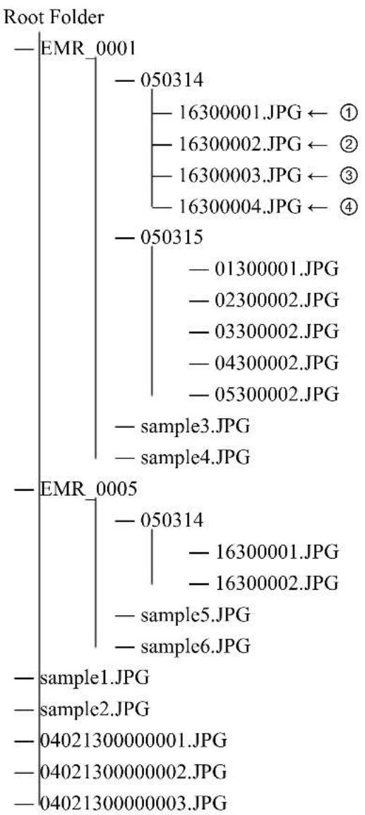
flowchart
graph TD
    A["Root Folder"] --> B["EMR_0001"]
    A --> C["EMR_0005"]
    B --> D["050314"]
    D --> E["16300001.JPG ← ①"]
    D --> F["16300002.JPG ← ②"]
    D --> G["16300003.JPG ← ③"]
    D --> H["16300004.JPG ← ④"]
    C --> I["050315"]
    I --> J["— 01300001.JPG"]
    I --> K["— 02300002.JPG"]
    I --> L["— 03300002.JPG"]
    I --> M["— 04300002.JPG"]
    I --> N["— 05300002.JPG"]
    C --> O["sample3.JPG"]
    C --> P["sample4.JPG"]
    C --> Q["sample1.JPG"]
    C --> R["sample2.JPG"]
    C --> S["sample2.JPG"]
    C --> T["sample2.JPG"]
    C --> U["sample2.JPG"]
    C --> V["sample2.JPG"]
In the above configuration, the folder in which the files selected by the □ button is looped. (In case ① is displayed in the above configuration, the displaying order is from ① \~ ④) When the application is started up, the screen is non-displaying (white).
External Dimensions
Units: mm

Note
| >100% of the total. |
ELMO
FOCUS ON THE FUTURE
ELMO USA Corp.
Headquarters
1478 Old Country Road
Plainview, NY 11803-5034, U.S.A.
Tel. (516) 501-1400 Fax. (516) 501-0429
E-mail: elmo@elmousa.com
Web: http://www.elmousa.com
West Coast Branch
Cypress Pointe Business Park
5676 Corporate Avenue
Cypress, CA 90630, U.S.A.
Tel. (714) 828-8457 Fax. (714) 828-8429
- WEB Server Function 42
- How To Set Up....52
- Screen Display Setup 69
- Log Display 83
- Equipment Maintenance 88
- Operation Under Error Status 91
- Troubleshooting 93
- Warranty and Services 94
- Introduction
- CAUTION
- WARNING
- IMPORTANT SAFETY INSTRUCTIONS
- PRECAUTIONS
- Before Use
- Installation
- Use Environment
- Handling
- Other Cautions
- Recording Medium (Hard Disk) and Radiating Fan
- Motion Detect (Movement Detection) Function
- System Structuring
- Ethernet Terminal
- When Malfunction Occurs
- Handling of Recorded Data
- Features
- ■ High Quality Digital Video and Sound Recording
- ■ Maximum of 4 Units of Large Capacity Hard Disk Drives Can Be Mounted
- ■ Handling Input from 16 Cameras
- ■ Simultaneous Operation of Recording, Playback and Live Display
- ■ 2 Types of Recording Modes
- ■ Motion Detect (Movement Detection) Function
- ■ Convenient Functions of Search and Playback
- ■ Capable of Remote Monitoring Via Network
- Accessories
- Names and Functions
- Front Face
- Back Face
- Connection
- Example of Connection with Alarm Devices
- ■ Connection with Sensor
- Example of Connection with External Control Equipment
- ■ Mouse
- ■ Ethernet
- Example of Connection with External Storage Media
- USB
- Example of Connection of PTZ Camera
- ■ PTZ (Pan, Tilt, Zoom) Camera
- Example of Connection with Expansion Hard Disk Unit
- How To Use
- Starting Up
- Turning Off
- Viewing Live Feeds iewing Live Feeds
- Switching Cameras
- Display in Split Screen
- Automatic Sequence Display
- PTZ Camera Control
- 2X Digital Zoom Display
- Viewing Live Feeds from Monitor 2
- Recording cording
- Note
- Manual Recording
- Using Automatic Recording Mode
- Playback ayback
- Playback/Stop Playback
- Changing Playback Speed
- Playback Frame by Frame
- Playback at Fast Speed
- How to Use LAYOUT Function
- Finishing LAYOUT Function
- Search and Playback Recorded Video
- Copy Function
- - USB
- • DVD
- How to Copy
- Stop Copying
- Image File Format Copied to USB Media
- Image File Format Copied to DVD
- WEB Server Function
- Functions
- Operation Environment
- Browser
- Java
- Login/Logout
- LIVE FEED
- PLAYBACK
- - Duplex Display
- MENU
- Main Menu
- E-Mail Function
- How To Set Up
- How to Start and Finish Menu Mode
- Operation of Menu Screen
- List of Menu Functions
- Main menu screen
- Recording Setup
- Recording Conditions Setup
- • TOTAL REC RATE
- • ESTIMATED REC RATE
- ■ Setup of Image Quality
- Recording Schedule Setup
- Concurrent Recording Camera Setup
- Holiday Setup
- Motion Setup
- Screen Display Setup
- Monitor Output Setup
- Automatic Sequence Setup
- Camera Name Setup
- Network Setup
- IMPORTANT!
- E-mail Setup
- Sending Condition Setup
- Control Camera Setup Screen
- User Setup
- Log Display
- Recording Log
- Error Log
- Startup Log
- User Log
- Equipment Maintenance
- Writing Method
- How to Format Hard Disks
- Operation Under Error Status
- Hard Disk Error
- Video Loss
- Output under Error Status
- Troubleshooting
- Warranty and Services
- Warranty
- When requesting repair during warranty period
- Repair after expiration of warranty period
- Inquiry
- Repair Parts
- Specifications
- Appendix
- Recording Time Table
- ■ Mirroring Recording Using 4 Units of 250GB HDD
- ■ Extended Recording Using 4 Units of 250GB HDD 4
- JPEG Display Software: "Resize Viewer"
- Operation Requirements
- File Display Order
- External Dimensions
- ELMO
- FOCUS ON THE FUTURE
- ELMO USA Corp.
Brand : Elmo
Model : EMR-16
Category : Digital recorder