
NRGence PE6108A - Power Supply ATEN - Free user manual and instructions
Find the device manual for free NRGence PE6108A ATEN in PDF.


| Product Type | Intelligent PDU (Power Distribution Unit) with energy meter |
| Dimensions (W x D x H) | 432 x 158 x 44 mm |
| Weight | 2.8 kg |
| Input Voltage | 100-240 VAC, 50/60 Hz |
| Output Voltage | 100-240 VAC |
| Rated Current | 16 A |
| Maximum Power | 3680 VA |
| Number of Outlets | 8 IEC C13 outlets |
| Input Plug Type | C14 power cord |
| Measurement Functions | Current, voltage, active power, apparent power, power factor, energy |
| Network Interface | Ethernet 10/100 Mbps, RJ45 port |
| Supported Protocols | HTTP, HTTPS, SNMP v1/v2c/v3, Telnet, SSH, DHCP, NTP |
| Environmental Sensors | Temperature and humidity (port for external sensor) |
| Remote Control | Individual outlet on/off, scheduling, sequences |
| Local Display | 2-line LCD screen, navigation buttons |
| LED Indicators | Per outlet: status (on/off), overload |
| Protection Device | 16A magnetic circuit breaker |
| Rack Mounting | 1U, mounting kit included |
| Housing Material | Steel, epoxy coating |
| Operating Temperature | 0°C to 50°C |
| Operating Humidity | 20% to 80% RH (non-condensing) |
| Maintenance and Cleaning | Dust with a dry cloth, do not use liquids |
| Spare Parts and Repairability | Repair reserved for qualified personnel; parts: power cord, fuse, external sensor |
| Standards and Certifications | CE, RoHS, FCC Class A |
| Warranty | 2 years |
Frequently Asked Questions - NRGence PE6108A ATEN
User questions about NRGence PE6108A ATEN
0 question about this device. Answer the ones you know or ask your own.
Ask a new question about this device
Download the instructions for your Power Supply in PDF format for free! Find your manual NRGence PE6108A - ATEN and take your electronic device back in hand. On this page are published all the documents necessary for the use of your device. NRGence PE6108A by ATEN.
USER MANUAL NRGence PE6108A ATEN
This equipment has been tested and found to comply with the limits for a Class A digital device, pursuant to Part 15 of the FCC Rules. These limits are designed to provide reasonable protection against harmful interference when the equipment is operated in a commercial environment. This equipment generates, uses, and can radiate radio frequency energy and, if not installed and used in accordance with the instruction manual, may cause harmful interference to radio communications. Operation of this equipment in a residential area is likely to cause harmful interference in which case the user will be required to correct the interference at his own expense.
The device complies with Part 15 of the FCC Rules. Operation is subject to the following two conditions: (1) this device may not cause harmful interference, and (2) this device must accept any interference received, including interference that may cause undesired operation.
FCC Caution
Any changes or modifications not expressly approved by the party responsible for compliance could void the user's authority to operate this equipment.
Warning
Operation of this equipment in a residential environment could cause radio interference.
Achtung
This product is RoHS compliant.
PE Device Safety Notice

- Set the maximum permissible breaker protection in the building circuitry to the current rating specified on the rating plate. Observe all national regulations and safety codes as well as deviations for breakers.
- Only connect the PE Device to a grounded power outlet or a grounded system!
Make sure that the total current input of the connected systems does not exceed the current rating specified on the rating plate of the PE Device.
There is a risk of explosion if the battery is replaced with an incorrect type. Dispose of used batteries according to the relevant instructions.
This user manual is provided to help you get the most out of your eco PDU. It covers all aspects of the power distribution unit, including installation, configuration, and operation.
The eco PDU models covered in this manual include:
| Model |
| PE6108AV |
| PE6208AV |
| PE8208AV |
An overview of the information found in the manual is provided below.
Chapter 1, Introduction, introduces you to the eco PDU, its purpose, features, and benefits, with its front and back panel components described.
Chapter 2, Hardware Setup, provides step-by-step instructions for setting up the eco PDU.
Chapter 3, Basic Operation and First-Time Setup, explains the basic operations of the eco PDU, and the necessary configurations for first-time setup.
Chapter 4, Browser Operation, describes how to log into the eco PDU remotely from a web browser, and the various functions it provides.
Chapter 5, Telnet Access, describes how to connect to and remotely access the eco PDU via Telnet.
Appendix, provides specifications and other technical information regarding the eco PDU.
Conventions
This manual uses the following conventions:
Monospaced Indicates text that you should key in.
[ ] Indicates keys you should press. For example, [Enter] means to press the Enter key. If keys need to be chorded, they appear together in the same bracket with a plus sign between them: [Ctrl+Alt].
- Numbered lists represent procedures with sequential steps.
◆ Bullet lists provide information, but do not involve sequential steps.
Indicates selecting consecutive options (such as on a menu or dialog box). For example, Start > Run means to open the Start menu, and then select Run.

Indicates critical information.
Package Contents
◆ 1 PE6108AVA / PE6208AV series / PE8208AV series
Power Distribution Unit
◆ 1 power cord (inapplicable to PE6208AVX)
◆ 1 RJ-45 cable
◆ 1 cable tie (PE6208AV series only) / 4 cable ties (PE8208AV series only) / 10 cable ties (only for J plug)
◆ 1 foot pad set (4 pcs)
◆ 1 mounting kit
◆ 1 user instructions*
Check to make sure that all of the components are present and in good order. If you encounter any problems, contact your dealer.
Read this manual thoroughly and follow the installation and operation procedures carefully to prevent any damage to the unit or to any other devices on the eco PDU installation.
Product Information
For information about all ATEN products and how they can help you connect without limits, visit ATEN on the Web or contact an ATEN Authorized Reseller. Visit ATEN on the Web for a list of locations and telephone numbers:
| International http://www.aten.com |
| North America http://www.aten-usa.com |
User Information
Online Registration
Be sure to register your product at our online support center:
| International http://eservice.aten.com |
Telephone Support
For telephone support, call this number:
| International 886-2-86 | 92-6959 |
| China 86-400-810-0-8 | 10 |
| Japan 81-3-5615-581 | 1 |
| Korea 82-2-467-6789 | |
| North America 1-888- | 999-ATEN ext 4988 |
| 1-949-428-1111 |
User Notice
All information, documentation, and specifications contained in this manual are subject to change without prior notification by the manufacturer. The manufacturer makes no representations or warranties, either expressed or implied, with respect to the contents hereof and specifically disclaims any warranties as to merchantability or fitness for any particular purpose. Any of the manufacturer's software described in this manual is sold or licensed as is. Should the programs prove defective following their purchase, the buyer (and not the manufacturer, its distributor, or its dealer), assumes the entire cost of all necessary servicing, repair and any incidental or consequential damages resulting from any defect in the software.
The manufacturer of this system is not responsible for any radio and/or TV interference caused by unauthorized modifications to this device. It is the responsibility of the user to correct such interference.
The manufacturer is not responsible for any damage incurred in the operation of this system if the correct operational voltage setting was not selected prior to operation. PLEASE VERIFY THAT THE VOLTAGE SETTING IS CORRECT BEFORE USE.
If any bodily injury or property damage with respect to operation of the product results from users not having installed the product in accordance with the instructions provided in the product's user manual, or the product is used in an environment with a current load over the designed specifications of the product, ATEN is not liable for any loss or damage.
Contents
EMC Information....ii
About This Manual ......iv
Conventions v
Package Contents v
Product Information ...... vi
User Information ...... v
Online Registration . . . . . . . . . . . . . . . . . . . . . . . . . . . . . . . . . . . . . . . . . . . . . . . . . . . . . . . . . . . . . . . . . . . vi
Telephone Support....vi
User Notice....vii
Contents viii
Chapter 1. Introduction
Overview....1
Features 3
Connections 3
Metering 3
Outlet Switch Control 3
Requirements 4
Optional Accessories 5
Sensors....5
Cable Holders 5
Components 6
PE6108AV / PE6208AV / PE8208AV Front View 6
PE6108AV / PE6208AV / PE8208AV Rear View (exclude PE6208AVX)
8
PE6208AVX Rear View. 9
Chapter 2.Hardware Setup
Before You Begin 11
Stacking and Rack Mounting 11
Stacking 11
Rack Mounting 13
Power Cord Installation (PE6208AVX) 15
Before Installation 15
Cord Selection....15
Plug Selection 15
Installation....16
Installation....19
Securing the Cables 21
Securing the Sensors 22
Chapter 3.Basic Operation and First Time-Setup
Operation Methods ...... 23
Browser....23
eco DC 23
SNMP 23
First-Time Setup 24
Network Configuration....25
Changing the Administrator Login . . . . . . . . . . . . . . . . . . . . . . . . . . . . . . . . . . . . . . . . . . . . . . . . . 26
Moving On....26
Chapter 4. Browser Operation
Logging In 27
The eco PDU Main Page 28
Page Components....28
Energy....30
Connections 30
Configuration (PE6208AV) 34
Configuration (PE8208AV) 36
User....42
Administrator Information 42
User Information 43
Log 45
The System Log Event List 45
Notification Settings....46
Setup....47
Device Configuration....47
Date/Time 53
Security 55
Login Failures ....55
Working Mode....55
Session Timeout ....55
Account Policy....56
Login String / IP Filter / Mac Filter .....57
Authentication & Authorization 60
Private Certificate 61
PDU....63
Firmware File. 63
Chapter 5.RS-232 / Telnet Commands
Remote Terminal Operations 67
Telnet 67
RS-232 Serial Control....69
Commands 70
Verification....70
Read Outlet Status ....71
Switch Outlet Status 73
Read Power Value 75
Read Environmental Value 77
Close Telnet Session 78
Safety Instructions 79
General 79
The eco PDU's Main Power Cord 85
Securing the Power Cables....85
Montage sur bâti 86
Technical Support. 88
International 88
North America....88
IP Address Determination....89
Specifications 91
PE6108AVA 91
PE6208AVA / PE6208AVB / PE6208AVG / PE6208AVX. . . . . . . . 9 3
PE6208AVJ Japan 95
PE8208AVB / PE8208AVG. 97
PE8208AVJ Japan 99
Administrator Login Failure....101
Limited Warranty....102
Overview
ATEN NRGence PE6108AV / PE6208AV / PE8208AV eco PDUs are intelligent PDUs that contain 8 AC outlets with a detachable front panel for convenient rack mounting and are available in various IEC or NEMA socket configurations.
They provide secure, centralized, intelligent, power management (power on, off, cycle) for data center IT equipment (servers, storage systems, KVM switches, network devices, serial data devices, etc.), as well as the ability to monitor the center's health environment via sensors*. The basic characteristics of each model are shown in the table on page 3.
NRGence eco PDUs offer remote power control combined with real-time power measurement - allowing you to control and monitor the power status of devices attached to the PDUs, either at the PDU and outlet level (PE8208AV) or Bank level (PE6208AV), from practically any location via a TCP/IP connection.
The power status of each outlet can be set individually, allowing users to switch each device On/Off. The eco PDU also offers comprehensive power analysis reports when used with the eco DC (eco PDU manager web GUI) which can separate departments and locations, providing precise measurements of current, voltage, power and watt-hour in a real-time display.
Installation and operation is fast and easy: plugging cables into their appropriate ports and user-friendly browser-based configuration and management is all that is entailed. Since the eco PDU firmware is upgradeable over the Net, you can stay current with the latest functionality improvements simply by downloading updates from our website as they become available.
NRGence eco PDU supports any 3rd party v3 SNMP manager software and NRGence eco DC (eco PDU manager web GUI). NRGence eco DC provides you with an easy method for managing multiple devices, offering an intuitive and user-friendly Graphical User Interface that allows you to configure a PDU device and monitor power status of the equipment connected to it.
This series of ATEN eco PDUs have threshold alerts that can sound an alarm and send SNMP trap or e-mail alerts when a threshold is exceeded. This feature
provides a faster response time to recover servers and other devices when the outlets surpass thresholds set by you.
The PE6108AV / PE6208AV / PE8208AV is an excellent fit for any ATEN VanCryst Pro A/V or VK Control System installation. Using our cross platform solutions not only provide you with the best performance but also utilize extra features which bring you more confidence and more power to control.
With its advanced security features and ease of operation, the eco PDU is the most convenient, most reliable, and most cost effective way to remotely manage power access for multiple computer installations and allocate power resources in the most efficient way possible.
Note: Sensors are optional accessories. A sensor-enabled installation is required to generate a more complete energy-efficient data and chart. Higher sensor installation density is helpful to generate more accurate data. See Optional Accessories, page 5, for further information.
Features
Connections
◆ Space saving 1U rack mount design with rear mounting
- Detachable front panel for convenient rack mounting
◆ Supports 10/100Mbit Ethernet Interface
◆ Supports TCP/IP, UDP, HTTP, HTTPS, SSL, DHCP, SMTP, ARP, NTP, DNS, Auto Sense, Ping, SNMP V1, V2, and V3, Telnet
- Supports 2-level account/password security, IP/MAC filter, TLS 1.0, RADIUS
- Management support via eco DC and web browser (IE, Firefox, Chrome, Safari)
Additional functions available with ATEN VanCryst Pro A/V & VK Control System installations
Metering
- Bank-level power metering and monitoring (PE6208AV); or PDU and outlet-level power metering and monitoring (PE8208AV)
- Environment monitoring — supports external temperature and/or humidity sensors for rack temperature and humidity monitoring
- Current, voltage, power, power dissipation, temperature, and humidity metering and threshold level setting
Outlet Switch Control
- Remote power outlet control (on/off, power cycle) by individual outlets and outlet groups
◆ Outlet group support at the PDU level - Supports multiple power control methods — Wake on LAN, System After AC Back, Kill the Power
- Power-On sequencing — users can set the power-on sequence and delay time for each outlet to allow equipment to be powered on in the correct order
- Local power on/off/reboot control via RS-232 port
- Proactive Overload Protection (POP) — automatically powers off outlets when current overloads to protect connected devices
Requirements
- Browsers accessing the eco PDU unit must support TLS 1.0.
- For cold booting of attached computers, the computer's BIOS must support Wake on LAN or System after AC Back.
- For Safe Shutdown:
- The computer must be running Windows (Windows 2000 or higher) or Linux.
- The Safe Shutdown program — PMonitor — must be installed and running on the computer (available by download from our website).
Note: Safe shutdown program PMonitor can be downloaded from the Support and Download section of the product web page, as shown below
| OS | Description | Ver. | Release Date | File Name |
| Other | ||||
| MIB File | v1.1.115 | 2015-05-05 | PE_MIB_File_v1.1.115.zip | |
| PE MIB File | v1.1.112 | 2014-06-19 | PE8_MIB_File_v1.1.112.tar | |
| PE MIB File | v1.1.109 | 2013-09-06 | PE8_MIB_File_v1.1.109.tar | |
| IP Installer | v1.4.132 | 2012-02-10 | IPinstaller-ALTUSEN_v1.4.132.zip | |
| Linux | PMonitor | v1.1 | 2012-02-10 | PowerMonitor_v1.1.zip |
| Windows | PMonitor | v1.0.081 | 2012-02-10 | PMonitorSrv_v1.0.081.zip |
| PE MIB File | v1.0.063 | 2012-02-10 | PE8_MIB_File_v1.0.063.zip | |
Optional Accessories
Sensors
Sensors are optional accessories. You can use the eco PDU unit without sensors. However, if you want to have complete energy management of an instrumented data center with the use of the eco PDU, you would need to use eco DC, a management web GUI, and install 4 sensors for each of the racks to generate a complete energy-efficient data and chart. Higher sensor installation density is helpful to generate more accurate data. 8-port models have 2 sensor ports. In this case, Sensor 1 needs to be installed at the intake of the rack and sensor 2 needs to be placed at the exhaust of IT equipment of the rack. A sensor-enabled installation is required to generate a more complete energy-efficient data and chart. Higher sensor installation density is helpful to generate more accurate data. Available sensors are show in the table, below:
| Sensor Part Number | |
| Temperature EA1140 | |
| Temperature / Humidity EA1240 | |
| Differential Pressure / Temperature EA1340 | |
Sensor Management
Sensors can be managed via the eco PDU's built-in graphical user interface (GUI) or with NRGence eco DC that can be downloaded from the ATEN website. The download link can be found on the software CD provided with the eco PDU package.
Cable Holders
Cable holders are optional accessories. For added safety, use ATEN Lok-U-Plug cable holders to secure the cables from your attached devices in place on the eco PDU unit. Use only the ATEN Lok-U-Plug cable holders that have been specifically designed to work with the eco PDU. Using any other kind of cable securing device could be highly dangerous.
| Part Number Description | |
| 2X-EA07 Lok-U-Plug Cable Holder (10 pcs) | |
| 2X-EA08 Lok-U-Plug Installation Tool (4 pcs) |
Components
PE6108AV / PE6208AV / PE8208AV Front View
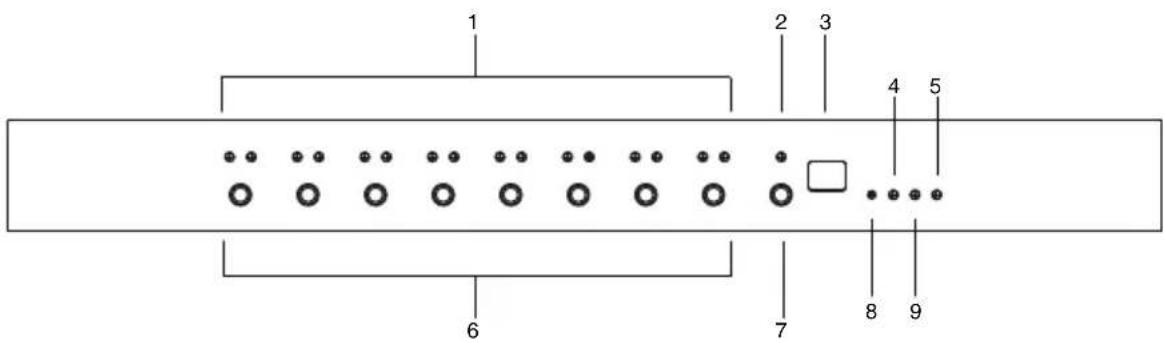
No. Item Description
| 1 port LEDs The port LEDs provide status information about their corresponding AC outlet ports. There is one pair of LEDs for each port. The one on the left is the Local LED; the one on the right is the Power LED:◆ A Local LED lights GREEN to indicate that the device attached to its corresponding port is capable of being controlled locally via the Power Control Button. The Local Mode is enabled/disabled with the Outlet Locked check box in the web GUI.◆ A Power LED lights ORANGE to indicate that there is electricity going to its corresponding outlet. The LED flashes under the following conditions:◆ If Modem Ring Resume is enabled (see Modem Ring Resume*, page 30), an outlet still receives electricity even when its corresponding computer has been powered OFF. The Power LED blinks OFF, then ON for 8 seconds, then OFF, then ON for 8 seconds, etc., to indicate this situation.◆ When a power status change is pending, the LED flashes until the change has taken place.◆ If both LEDs flash it indicates that there is either an overcurrent situation, or the relay has failed. | |
| 2 current LED | Lights to indicate that the Current (in amps) is being displayed on the status LED. |
| No. | Item Description | |
| 3 | status LED The | current (in amps), IP address or Holiday Mode status displays here. You can switch between the current and IP status using the current / IP switch (see item 7, below).◆ When the current status is displayed the current LED (see above) lights RED.◆ When the IP status is selected, the unit's IP address (two digits of an octet at a time) will be shown, twice.◆ When Holiday Mode is enabled the status LED displays hd (see Holiday Mode, page 41). |
| 4 | 10/100 Mbps data LED | ◆ The LED lights ORANGE to indicate 10 Mbps data transmission speed.◆ The LED lights GREEN to indicate 100 Mbps data transmission speed. |
| 5 | power LED Lights when the PDU is powered up and ready to operate. | |
| 6 | power control buttons | Each button (1 to 8), controls the power status of its corresponding AC output port as follows:◆ Under Local Mode, pressing and holding the button in for more than 3 seconds switches the power to its corresponding port On or Off.◆ Pressing and holding button (1) in for more than 8 seconds sequentially reboots all outlets.◆ Pressing and holding button (8) in for more than 8 seconds enables/disables Holiday Mode (see Holiday Mode, page 41). |
| 7 | current / IP switch | Switches displaying the current (in amps) – to displaying the IP address on the status LED.◆ When pushed, the status LED will display the unit's IP address (two digits of an octet at a time) twice and then switch back to displaying the current. |
| 8 | reset button | Press and release to reboot the PDU. Pressing and holding this button for more than three seconds resets the PDU to its factory default settings. This button is recessed and must be pushed with a thin object, such as the end of a paper clip, or a ballpoint pen. |
| 9 | link LED Lights | GREEN to indicate that a connection via the PDU's RJ-45 Ethernet port has been established. Flashes to indicate that data is being transmitted. |
PE6108AV / PE6208AV / PE8208AV Rear View (exclude PE6208AVX)
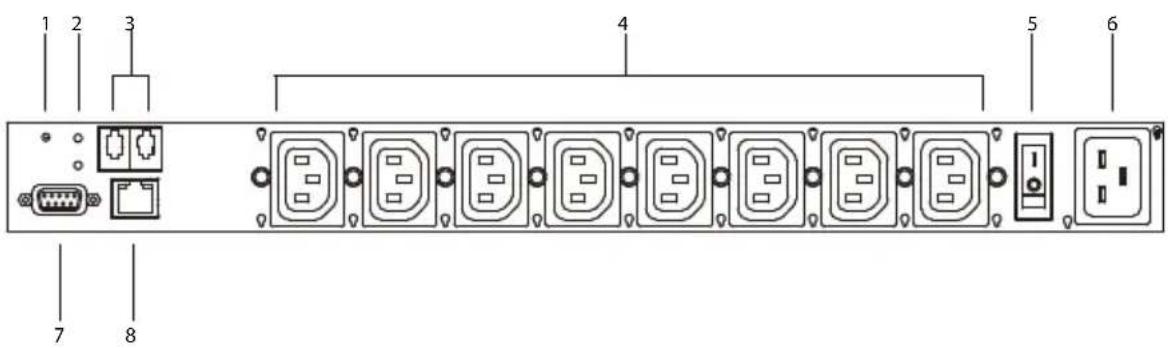
PE6208AVG rear view is used as the example above.
| No. | Item Description | |
| 1 | resetbutton | Press and release to reboot the PDU. This button is recessed and must be pushed with a thin object, such as the end of a paper clip, or a ballpoint pen. |
| 2 | sensorLEDs | Two sensor LEDs light GREEN when a sensor is connected to the respective sensor port. |
| 3 | sensorports | External sensors plug into these two RJ-11 ports. |
| 4 | powersockets | The power cables that connect to the computers plug in here. |
| 5 | powerswitch | This standard rocker switch powers the PE6108AV / PE6208AV / PE8208AV on or off. |
| 6 | powersocket | The power cable from the AC source plugs in here. |
| 7 | RS-232port | This port can be used to attach to a computer for local power on/off/reboot control. |
| 8 | LAN port The Cat 5e cable that connects the PE6108AV / PE6208AV / PE8208AV to the Internet plugs in here. | |
PE6208AVX Rear View
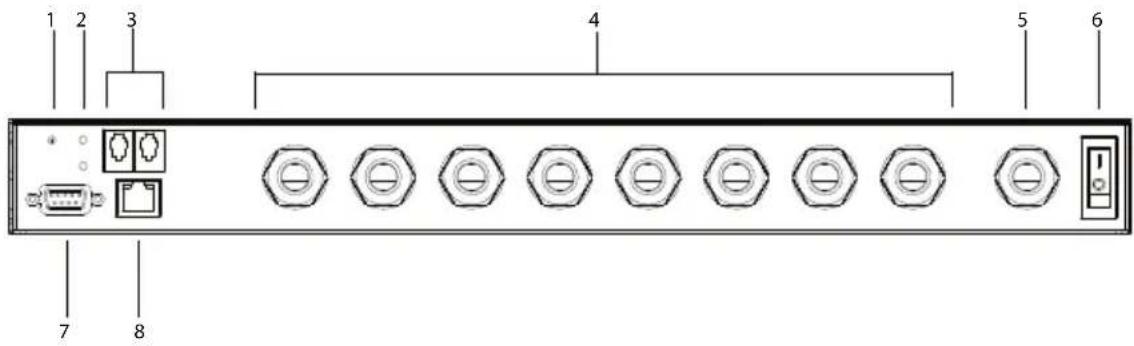
| No. | Item Description | |
| 1 | resetbutton | Press and release to reboot the PDU. This button is recessed and must be pushed with a thin object, such as the end of a paper clip, or a ballpoint pen. |
| 2 | sensorLEDs | Two sensor LEDs light GREEN when a sensor is connected to the respective sensor port. |
| 3 | sensorports | External sensors plug into these two RJ-11 ports. |
| 4 | poweroutlet cableglands | Connect power of computers here. Please refer to Power Cord Installation (PE6208AVX) on page 15. |
| 5 | power inletcable gland | Connect AC source here. Please refer to Power Cord Installation (PE6208AVX) on page 15. |
| 6 | powerswitch | This standard rocker switch powers the PE6208AVX on or off. |
| 7 | RS-232port | This port can be used to attach to a computer for local power on/off/reboot control. |
| 8 | LAN port The Cat | at 5e cable that connects the PE6208AVX to the Internet plugs in here. |
This Page Intentionally Left Blank
Before You Begin

Stacking and Rack Mounting
Stacking
The PE6108AV / PE6208AV / PE8208AV can be placed on any appropriate level surface that can safely support its weight plus the weight of its attached cables. To place or stack the PE6108AV / PE6208AV / PE8208AV, remove the backing material from the bottom of the rubber feet that came with this package, and stick them onto the switch's bottom panel at the corners, as shown in the diagrams, below:
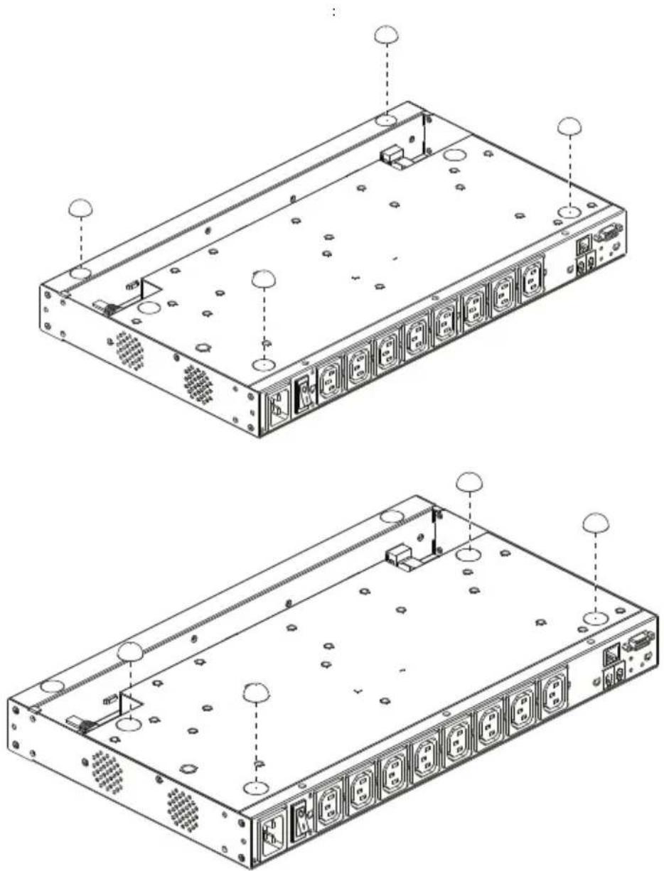
natural_image
Technical line drawings of a server rack with multiple ports and ventilation slots (no text or labels)Note: To ensure adequate ventilation, allow at least 5.1 cm on each side, and 12.7cm at the back for power cord and cable clearance.
Rack Mounting
The PE6108AV / PE6208AV / PE8208AV can be installed in most standard 19" (1U) racks. To rack mount the unit do the following:
- Separate the front and rear modules by removing the four module attaching screws:
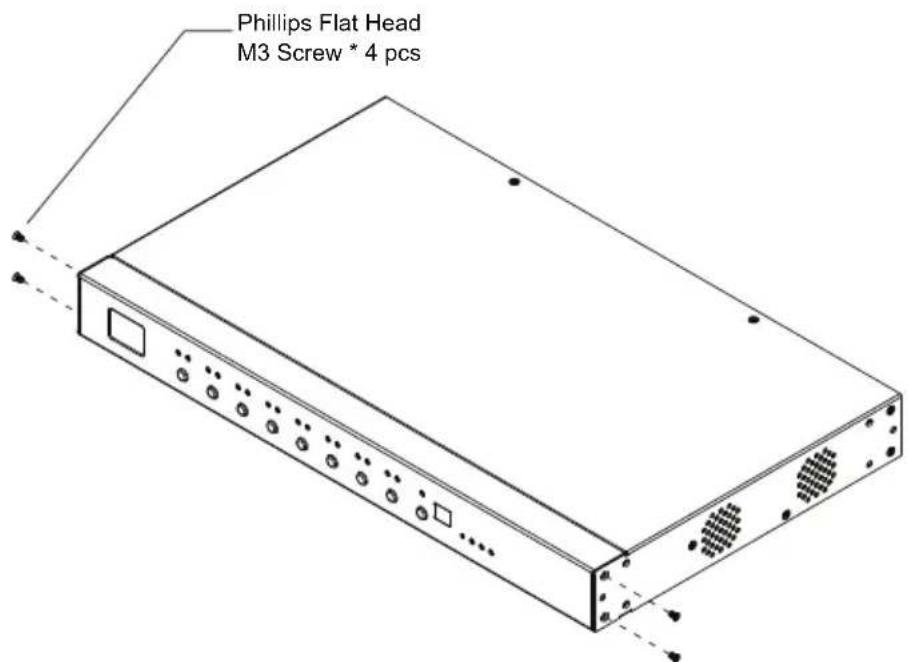
- Use the screws you just removed, and the ones supplied with the rack mounting kit to screw the rack mounting brackets into both modules:
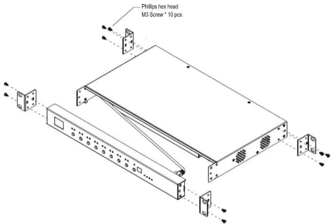
-
There is an RJ-45 port on the front panel and rear module used to connect the two units. A standard Ethernet cable can be used to extend the front panel and rear module farther apart.
-
Position the device in the rack and align the holes in the mounting brackets with the hole in the rack.
-
Screw the mounting brackets to the rack.
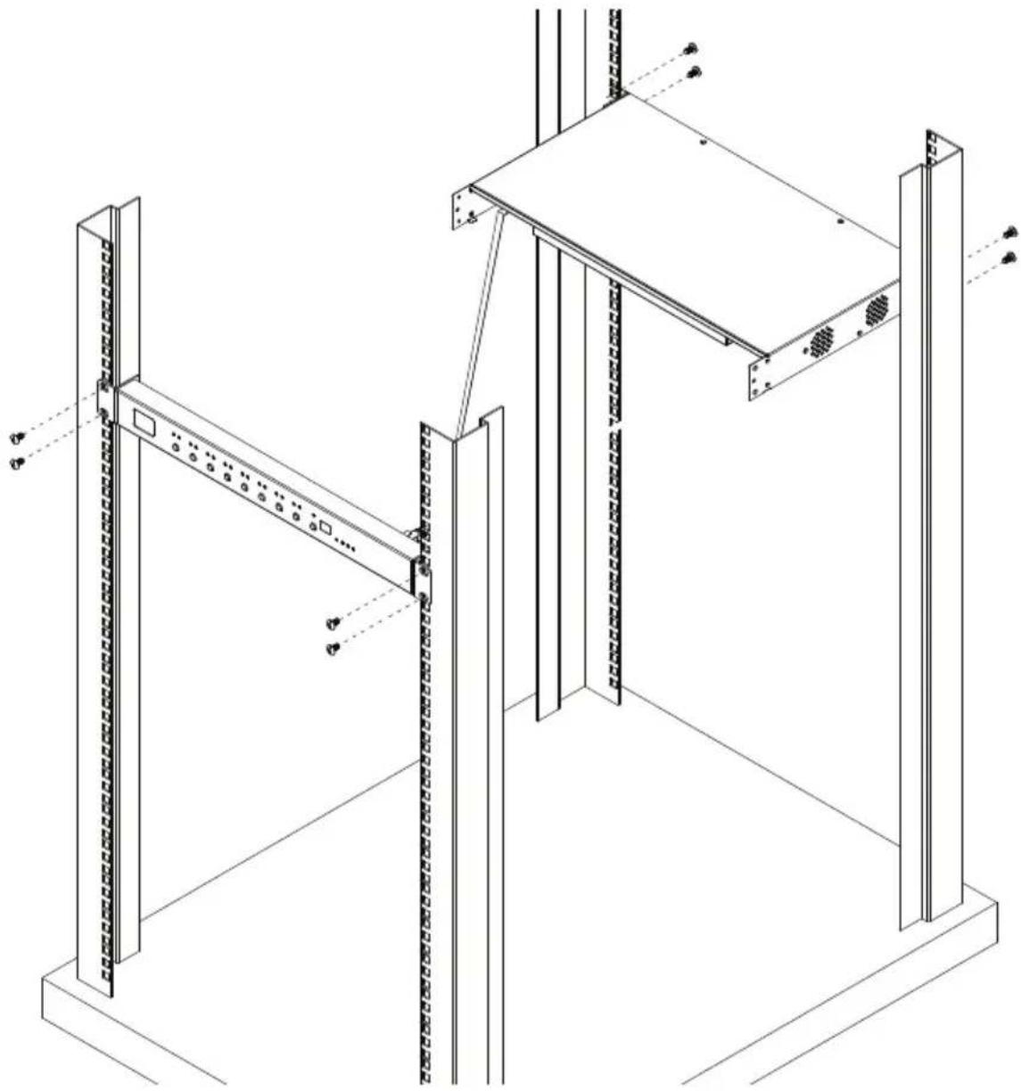
natural_image
Technical line drawing of a structural frame assembly with vertical supports and mounting brackets (no text or symbols)Note: Cage nuts are provided for racks that are not prethreaded.
Power Cord Installation (PE6208AVX)
The PE6208AVX eco PDU provides terminal blocks that allow for custom power cord installation. Please read the following precautions before proceeding to the installation instructions.
Before Installation
WARNING! Unless you are a licensed electrician, DO NOT perform wiring assembly for this product. Assembly or attempted assembly by unlicensed electricians may result in fire, personal injury, electrical shock, and death. If you are not a qualified electrician (having appropriate licensing and insurance) - STOP NOW. ATEN is not responsible for any damages to equipment or loss of data due to improper installation.
Cord Selection
- The preferred cable is a flexible 3.0m long (max), 14 AWG cord, or a 1.5mm ^2 , 3G flexible cord (e.g.: H05VV-F, 250V.), with a diameter of 7 - 10mm.
- The rated ampacity of the power cord must be greater than or equal to the product’s rated ampacity marked on its nameplate.
- The number of wires in the power cord must match the number of terminals (including the ground terminal).
- The power cord may be permanently connected to the power supply subject to local regulatory agency approval.
Plug Selection
- If a plug is to be attached to the power cord, the plug chosen should be 250V, 16A, 3C, IEC 60320 C19.
- For all other locations, subject to local regulatory agencies policies, the plug’s rated ampacity needs to be the same as the products rated ampacity.
Installation
These instructions must be performed by a licensed electrician.
- Remove the six screws from the cover covering the terminal block compartment.
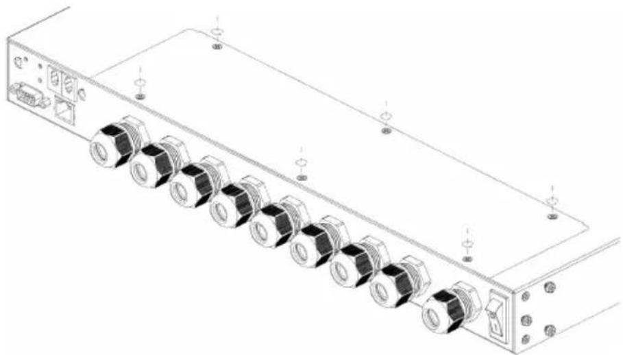
natural_image
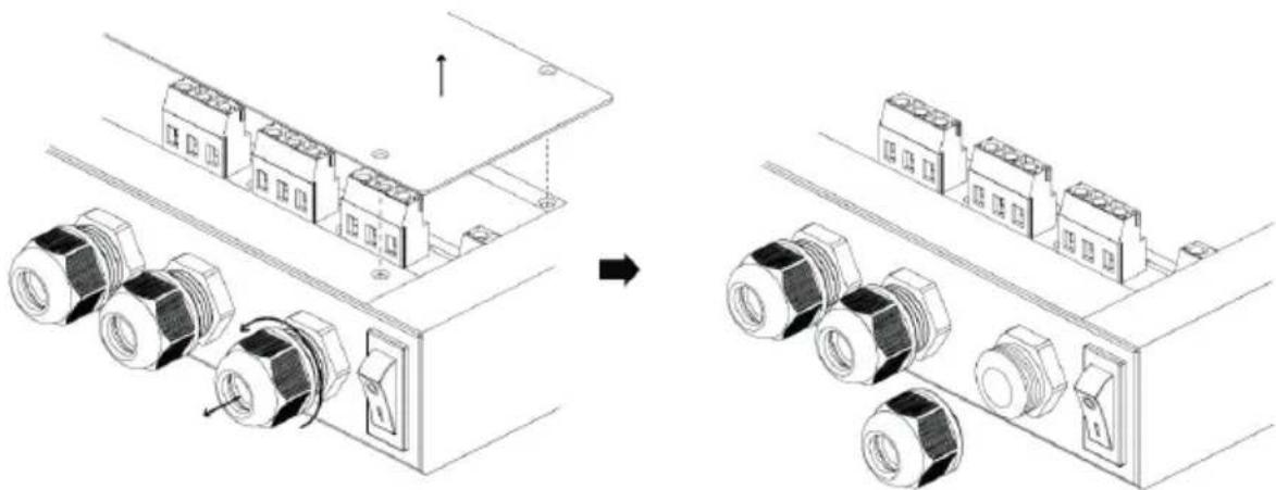
Technical line drawing of a server rack with multiple connectors and ports (no text or symbols)- Remove the cover from the compartment and loosen the cable gland by turning the gland nut counter-clockwise (use a dedicated spanner if required).
natural_image
Technical line drawing showing assembly of electrical connectors with bolted components (no text or symbols)- Strip off the outer jacket of the power cord using a wire stripper. Use the slot appropriate for the cord's size (refer to Cord Selection) on the wire stripper.
Make sure there is a length of 45-60mm exposed for the 3 inner wires and remove any jute, paper or other fillers.
- There should be 3 inner wires. Strip the wires using the appropriate slot (refer to Cord Selection) with the wire stripper.
Make sure there is a length of 6-7mm wire exposed for inserting into the terminal block.
- Add wire ferrules to the wires.
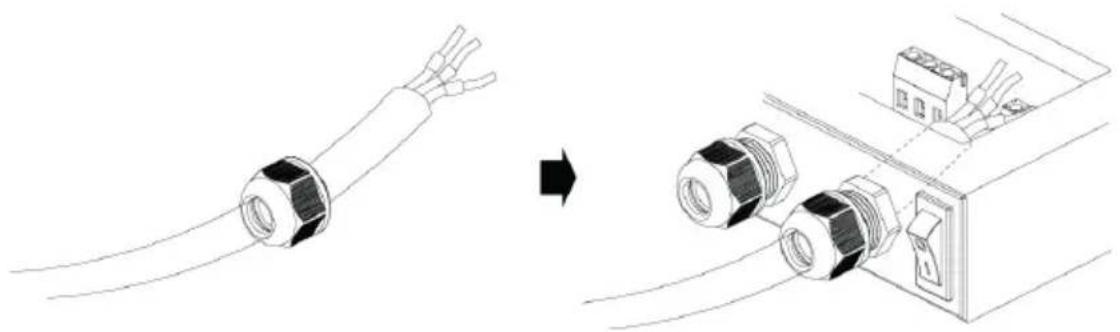
- Slide the power cord into the compartment through the cable gland and inner ring as shown below:
natural_image
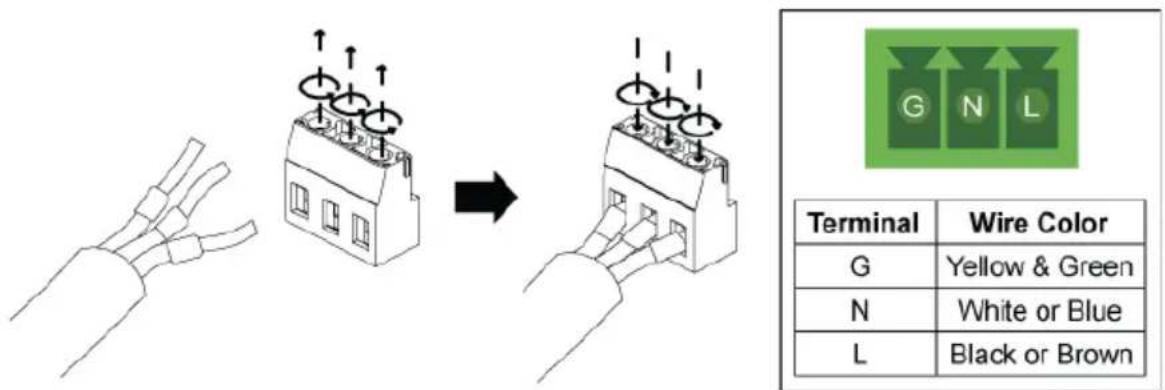
Diagram showing cable installation process: wire being replaced by connector (no text or symbols)- Open the gates of the power terminal block by loosening the screws on the top using a screwdriver. Insert the wires according to the table on the right. Tighten the screws on the top (to a torque of 0.5N.m) to secure the wires in the gates.
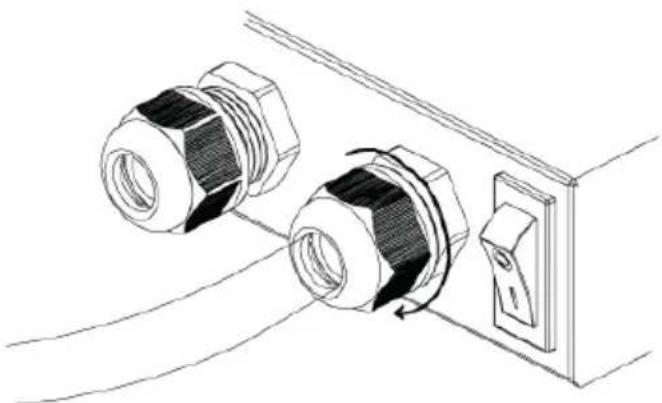
- Use a dedicated spanner where necessary, tighten the cable gland by turning the gland nut clockwise (to a torque of 2-3N.m) to secure the cable to the PDU unit. Verify that the power cord is secure and cannot be twisted, pushed or pulled in the gland.
natural_image
Technical line drawing of two bolted connectors connected to a switch (no text or symbols)- Replace the cover and tighten the six screws to secure it to the unit.
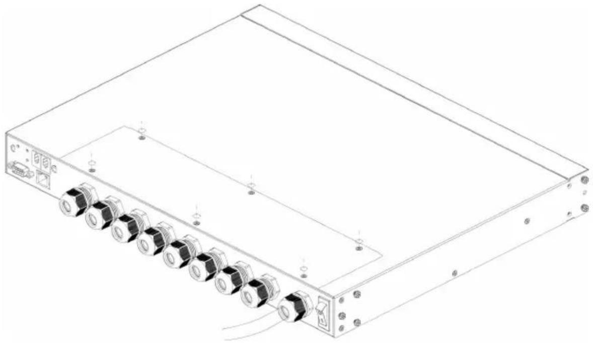
natural_image
Line drawing of a server rack with multiple ports and connectors (no text or symbols)Installation
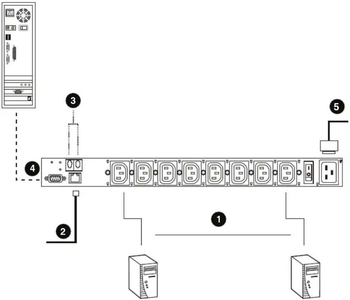
To install the PDU, refer to the installation diagram below (the numbers in the diagram correspond to the numbered steps), and do the following:
-
For each device you want to connect, use its power cable to connect from the device's AC socket to any available outlet on the eco PDU.
For PE6208AVX, please refer to Power Cord Installation (PE6208AVX). -
Plug the Ethernet cable into the eco PDU's LAN port to connect it to the network.
-
If you are using sensors in your eco PDU installation, connect them to the sensor ports on the unit's rear panel.
Note: Sensors are optional. Please see Optional Accessories, page 5, and the detailed sensor installation diagrams later in this chapter for further information.
-
If you choose to use a serial device for control, connect its serial port to the PE6108AV / PE6208AV / PE8208AV's RS-232 port.
-
Connect the eco PDU's power cord to an AC power source.
Note: We strongly advise that you do not plug the eco PDU into a multi socket extension cord, since it may not receive enough amperage to operate correctly.
- Once you have finished these installation steps, you can turn on the eco PDU and the connected devices.
Note: We strongly recommend using cable ties and cable bars to safely and securely route the cables attached to the front of the unit.
flowchart
graph TD
    A["Server"] -->|2| B["Port 1"]
    A -->|3| C["Port 2"]
    A -->|4| D["Port 3"]
    A -->|5| E["Port 4"]
    B --> F["Computer"]
    C --> G["Computer"]
    D --> H["Computer"]
    E --> I["Computer"]
PE6208AVG is the model used in the installation example picture above.
Securing the Cables
For added safety, use ATEN Lok-U-Plug cable holders (not for PE6208AVX) to secure the cables from your attached devices in place on the eco PDU unit. Secure the cable holders using the specially designed holes around the individual power outlets, as shown below:
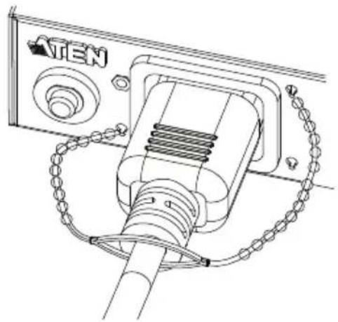
natural_image
Technical line drawing of a mechanical assembly with no visible text or symbolsNote: 1. Cable holders are an optional accessory. See Cable Holders, page 5.
- Use only the ATEN Lok-U-Plug cable holders that have been specifically designed to work with the eco PDU. Using any other kind of cable securing device could be highly dangerous.
Securing the Sensors
Connect the sensors to the eco PDU's rear panel sensor ports and secure them using sensor mounts, tie wraps, and adhesive cable tie holders. If you use a tie wrap to secure the sensor, tighten the tie wrap over the recessed channel on the sensor, as shown in the following diagram:
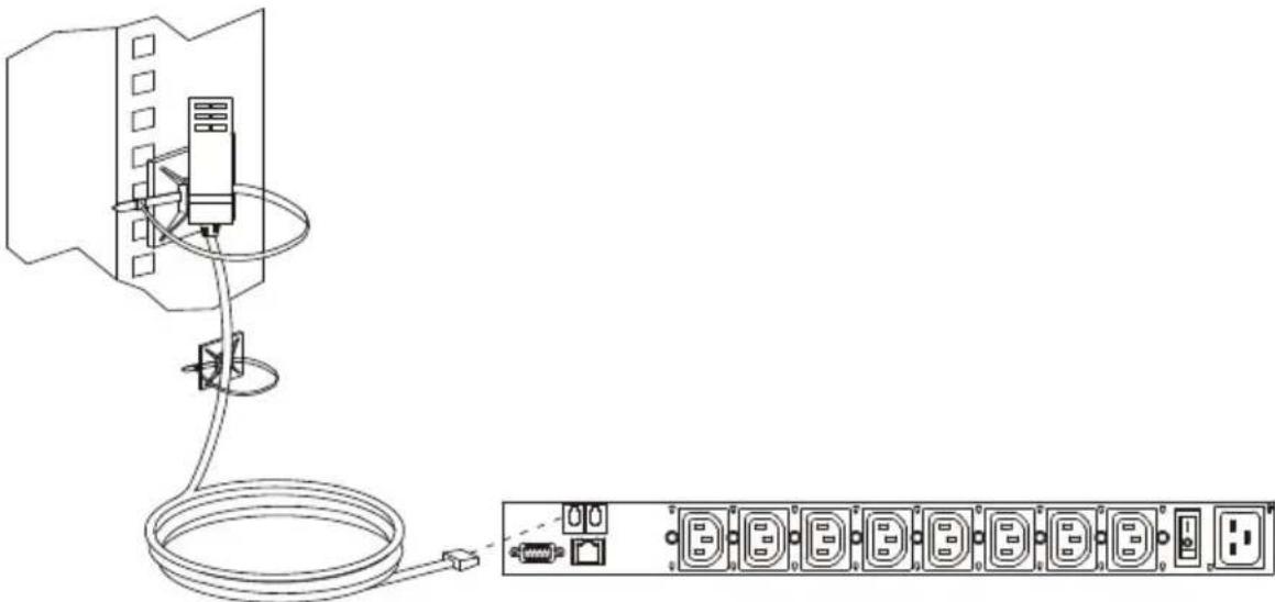
natural_image
Line drawing of an electrical connection setup with a cable and terminal block (no text or symbols)Note: 1. The sensors shown in the above diagram are for reference purposes only. The sensors for the eco PDU may look slightly different.
- Depending on the model and type of sensor, sensor mounts, tie wraps, and adhesive cable tie holders may or may not be provided in the package.
Chapter 3
Basic Operation and First-Time Setup
Operation Methods
NRGence eco PDU models provide three methods to access and manage your installation: Browser, eco DC (eco PDU management web GUI), and SNMP.
Note: The following sections of this chapter contain information concerning Browser operation. For eco DC operation, please reference the separate eco DC user manual. The eco DC web GUI and user manual can be downloaded from the ATEN website.
Browser
The eco PDU can be accessed and controlled via any supported Internet browser from any platform. See First-Time Setup, page 24, and the following sections in this chapter, for full details.
eco DC
The eco DC (eco PDU management web GUI) provides you with an easy method for managing multiple devices, offering an intuitive and user-friendly Graphical Interface that allows you to configure a PDU device and monitor power status of the equipment connected to it. eco DC can be downloaded from the ATEN website, along with a separate eco DC user manual.
SNMP
The eco PDU supports any 3rd party V3 SNMP Manager Software. SNMP Management Information Database (MIB) files for the eco PDU device can be found on the software CD provided with the eco PDU package.
First-Time Setup
Once the eco PDU installation has been cabled up, the next task the Administrator needs to perform involve configuring the network parameters, changing the default Super Administrator login settings, and adding users.
The way to accomplish this is to log in vi a web browser.
Note: 1. Since this is the first time you are logging in, use the default Username: administrator; and the default Password: password. For security purposes we recommend changing them to something unique (see Changing the Administrator Login, page 26).
2. For remote methods of getting logged in to the PDU, see IP Address Determination, page 89.
After you successfully log in, the eco PDU Energy/Connections page appears:
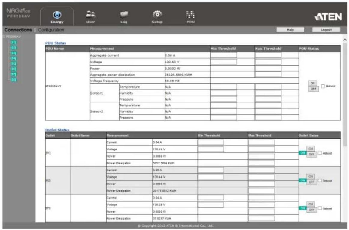
Note: Operation details are discussed in Energy, page 30, in the next chapter. For further setup information, continue with this chapter
Network Configuration
To configure the network settings, do the following:
- Click the Setup tab.
- The interface displays the Device Configuration page. A screen similar to the one below appears:
![NRGence PE6208AV Energy User Log Setup PDU Device Configuration | Security General POU Name: QA MAC Address: 00:10.74.9D.77.06 Firmware Version: FWV Ver:1.8.174 Rock Location name: test Service Ports Only HTTPS HTTP / HTTPS HTTP: 80 HTTPS: 443 IPv4 Configuration Obtain IP address automatically [DHCP] Set P address manually [Fixed IP] IP Address: Subnet Mask Default Gateway: Obtain DNS server address automatically Set DNS server address manually](/content/2026/05/957546/images/2b5916120f2a91d441d315ca27f706a21d43a9e77c39ae9651766e2fdedc34f3.jpg)
- Fill in the fields according to the information provided under Device Configuration, page 47.
Changing the Administrator Login
To change the default Administrator username and password, do the following:
1. Click the User tab.
The Accounts page has a detailed list of users – with more information about them – in the large central panel:
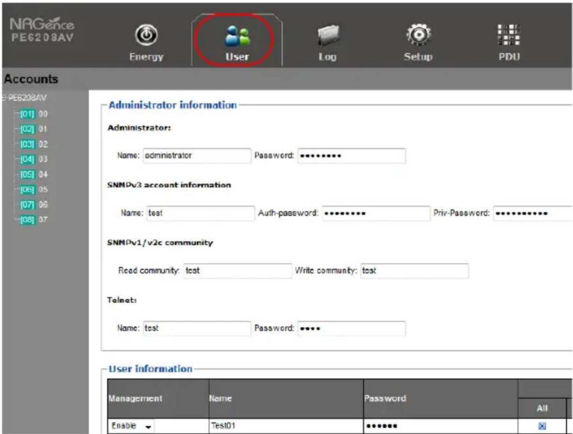
- In the Administrator Information section, reset the name and password fields to something unique, then click Save (at the bottom of the page.)
Note: If you forget the Administrator's name or password, short the mainboard jumper to restore the default Administrator account. See see Administrator Login Failure, page 101 in the Appendix for full details.
Moving On
After setting up the network and changing the default Administrator username and password, you can proceed to other administration activities – including adding users. This is covered in the next chapter.
Logging In
The eco PDU can be accessed via a supported Internet browser from any platform.
Note: Browsers must support TLS 1.0.
To access the eco PDU do the following:
- Open your browser and specify the IP address of the eco PDU you want to access in the browser's URL location bar.
Note: You can get the IP address from the eco PDU administrator, or see IP Address Determination, page 89, for information about setting it up yourself.
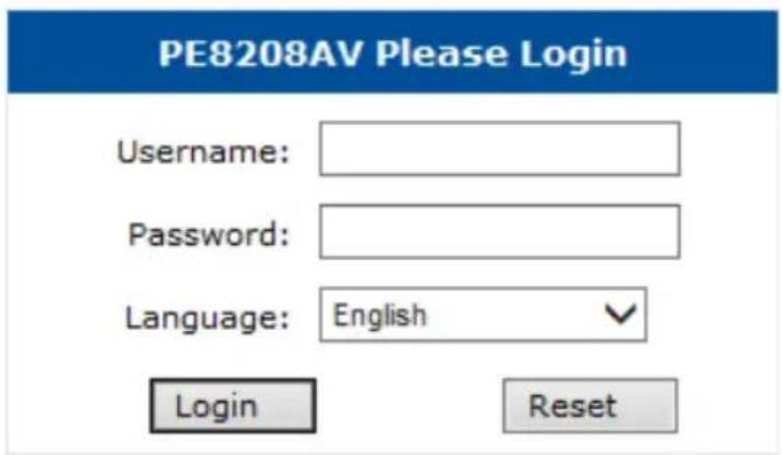
- If a Security Alert dialog box appears, accept the certificate – it can be trusted. The Login page appears:
-
Provide a valid Username and Password (set by the administrator), and select your language. (Options are: English [default]; Traditional Chinese; Simplified Chinese; Japanese; German; Italian; Spanish; French; Russian; Korean; Portuguese).
-
Then Click Login to bring up the browser Main Page.
The eco PDU Main Page
After you have successfully logged in, the eco PDU Main Page comes up with the Energy Connections page displayed:
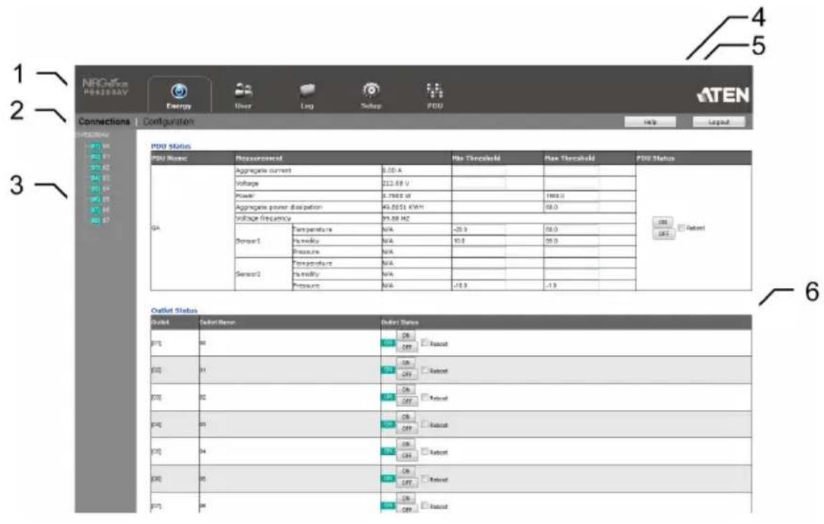
Note: The screen depicts an Administrator's page. Depending on a user's type and permissions, not all of these elements appear.
Page Components
The web page screen components are described in the table, below:
| No. | Item Description | |
| 1 | Tab Bar The tab bar contains | the eco PDU's main operation categories. The items that appear in the tab bar are determined by the user's type, and the authorization options that were selected when the user's account was created. |
| 2 | Menu Bar The menu bar contains | ains operational sub-categories that pertain to the item selected in the tab bar. The items that appear in the menu bar are determined by the user's type, and the authorization options that were selected when the user's account was created. |
| 3 | Sidebar The Sidebar provides | a tree view listing of outlets that relate to the various tab bar and menu bar selections. |
| 4 Help Connects to on-line help | at the ATEN website for the device's configuration and operation. | |
| 5 Logout Click this button to log | out of your eco PDU session. | |
| 6 Interactive Display Panel This | is your main work area. The screens that appear reflect your menu choices and Sidebar node selection. | |
Energy
Connections
When you log in to the eco PDU, the interface opens with its default selection of the Energy tab; and the Connections menu. The contents of the PDU Status and Outlet Status sections are displayed in the main panel.
![NRG60 PE8208AV Energy User Log Setup PDU Connections | Configuration Help Logout PDU Status PDU Name Measurement Min Threshold Max Threshold PDU Status PE8208AV1 Aggregates current 0.36 A OK □ Reboot Voltage 130.63 V OFF Power 0.0000 W N/A Aggregate power dissipation 35126.5891 KWH N/A N/A N/A N/A N/A N/A N/A N/A N/A N/A N/A N/A N/A N/A N/A N/A N/A N/A N/A N/A N/A N/A N/A N/A N/A N/A N/A N/A N/A N/A N/A N/A N/A N/A N/A N/A N/A N/A N/A N/A N/A N/A N/A N/A N/A N/A N/A N/A N/A N/A N/A N/A N/A N/A N/A N/A N/A N/A N/A N/A N/A N/A N/A N/A N/A N/A N/A "N/A Sensor1 Temperature N/A N/A N/A N/A N/A N/A N/A N/A N/A N/A N/A N/A N/A N/A N/A N/A N/A N/A N/A N/A N/A N/A N/A N/A N/A N/A N/A N/A N/A N/A N/A N/A N/A ,N/A Heddykry N/A N/A N/A N/A N/A N/A N/A N/A N/A N/A N/A N/A N/A N/A N/A N/A N/A N/A N/A N/A N/A N/A N/A N/A N/A N/A N/A N/A N/A N/A N/A N/A N/A LN Pressure N/A N/A N/A N/A N/A N/A N/A N/A N/A N/A N/A N/A N/A N/A N/4 Sensor2 Temperature N/A N/A N/A N/A N/A N/A N/A N/A N/A\\nA Heddykry N/A N/A N/A\\nA Pressure N/A N/A\\nA Outlet Status Outlet Coutlet name Measurement Min Threshold Max Threshold POutet States [51] Current 0.84 A Voltage 130.44 V Power 0.0000 W Power Dissipation 5857.5604 KWH Current 0.85 A Voltage 130.44 V Power 0.0000 W Power Dissipation 29177.8512 KWH Current 0.84 A Voltage 130.39 V Power 0.0000 W Power Dissipation 37.6257 KWH Outlet Status On OFF □Reboot On OFF □Reboot On OFF □Reboot On OFF □Reboot © Copyright 2012 ATEN □ International Co., Ltd.](/content/2026/05/957546/images/2656f79aa1ab027408ba2f0edc07b7a64c4b1d0caf48a665603b442e4b6a9c28.jpg)
Note: Only enabled eco PDU models will display the Outlet Status submenu section. Other models provide only PDU Status monitoring. See Features, page 3, for which models support PDU and Outlet Status or PDU Status only monitoring.
PDU Status
All eco PDU models support PDU device level monitoring. The PDU Status section allows you to set up a power management configuration for the PDU device as a whole:
PDU Status
| PDU Name | Measurement | Min Threshold | Max Threshold | PDU Status | ||||
| PE8206AV1 | Aggregate current | 0.36 A | ONOFF □ Reboot | |||||
| Voltage | 130.13 V | |||||||
| Power | 0.0000 W | |||||||
| Aggregate power dissipation | 35126.5891 KWH | |||||||
| Voltage frequency | 59.88 HZ | |||||||
| Sensor1 | Temperature | N/A | ||||||
| Humidity | N/A | |||||||
| Pressure | N/A | |||||||
| Sensor2 | Temperature | N/A | ||||||
| Humidity | N/A | |||||||
| Pressure | N/A | |||||||
■ PDU Threshold Settings
These fields are used to set the maximum, minimum, and fluctuation threshold settings for Aggregate Current, Voltage, Power, and Aggregate Power Dissipation. If a range falls below the minimum setting, or exceeds the maximum setting an alarm is triggered. The Aggregate Current Max Threshold setting triggers the Proactive Overload Protection (POP) mode (see page 34).
♦ Voltage Frequency is displayed here in Hz.
- On / Off / Reboot
You can manually turn the device On and Off from this page by clicking the radio buttons. To Reboot the device, enable the Reboot checkbox and click on Save (located at the bottom of the page).
- Sensor 1 / Sensor 2
If you have sensors installed in your installation, use these fields to set the maximum, minimum and fluctuation threshold settings for Temperature, Humidity, and Differential Pressure.
Note: Sensors are optional accessories. Check with your dealer for details.
Outlet Status (PE6208AV)
The PE6208AV supports on, off and reboot control from the outlet status column for each outlet.
Outlet Status
| Outlet | Outlet Name | Outlet Status | ||
| [01] | 00 | ON | ONOFF | Reboot |
| [02] | 01 | ON | ONOFF | Reboot |
| [03] | 02 | ON | ONOFF | Reboot |
| [04] | 03 | ON | ONOFF | Reboot |
| [05] | 04 | ON | ONOFF | Reboot |
■ On / Off / Reboot
You can manually turn the outlet On and Off from this page by clicking the radio buttons. To Reboot the outlet, enable the Reboot checkbox and click on Save (located at the bottom of the page).
Outlet Status (PE8208AV)
The PE8208AV supports outlet level monitoring; and on, off and reboot control. The main panel Outlet Status section allows you to set up a power management configuration for each outlet at an individual level.
Outlet Status
| Outlet | Outlet Name | Measurement | Min Threshold | Max Threshold | Outlet Status | |
| [01] | Current | 0.04 A | ||||
| Voltage | 129.98 V | |||||
| Power | 0.0000 W | |||||
| Power Dissipation | 5857.5604 KWH | |||||
| [02] | Current | 0.05 A | ||||
| Voltage | 129.98 V | |||||
| Power | 0.0000 W | |||||
| Power Dissipation | 29177.8512 KWH | |||||
| [03] | Current | 0.04 A | ||||
| Voltage | 129.98 V | |||||
| Power | 0.0000 W | |||||
| Power Dissipation | 37.0257 KWH | |||||
■ Outlet Threshold Settings
These fields are used to set the maximum, minimum, and fluctuation threshold settings for Current, Voltage, Power, and Power Dissipation. If a range falls below the minimum setting, or exceeds the maximum setting an alarm is triggered. The Current Max Threshold setting triggers the Proactive Overload Protection (POP) mode (see page 36).
■ On / Off / Reboot
You can manually turn the outlet On and Off from this page by clicking the radio buttons. To Reboot the outlet, enable the Reboot checkbox and click on Save (located at the bottom of the page).
Configuration (PE6208AV)
The Configuration page is used to configure the settings of the PE6208AV at the individual power outlet level.
POP Settings
□ Enable Bank POP Priority Mode
Power On Time Schedule Settings
□ Enable Power On Time Schedule
Buzzer Setting
Enable Buzzer Alarm
Outlet Reboot Setting
√ Enable Outlet Sequential Reboot
■ POP Settings
This section allows you to enable Proactive Overload Protection (POP). Proactive Overload Protection is triggered when the PDU's Aggregate Current Max Threshold setting is exceeded (see page 31). Effective on all outlets, this added safety feature automatically powers off the outlets according to the settings below:
- Enable Bank POP Priority Mode checking this box enables Proactive Overload Protection and will power off outlets according to the Bank POP Priority List (see page 35).
■ Power On Time Schedule Settings
Check the Enable Power On Time Schedule box to use the Power ON Delay setting to set the amount of time the eco PDU waits before powering on an outlet. See Power ON Delay in the table on the next page.
■ Buzzer Setting
Checking the Enable Buzzer Alarm box sounds an alarm and sends SNMP trap or e-mail alerts when a threshold setting exceeds the minimum or maximum setting.
■ Outlet Reboot Setting
Checking the Enable Outlet Sequential Reboot box allows you to sequentially reboot all outlets by pressing the Power Control Button of Outlet 1 for more than 8 seconds.
■ Bank POP Priority List
Use the eight drop-down menus to set the priority for when Proactive Overload Protection powers off the outlets. The outlet set as Priority1 will be powered off first, Priority2 will be powered off second, and so on. Outlets set to N/A will not be powered off when Proactive Overload Protection is triggered.
To change the Priority List, set at least two drop-down menus to N/A. Outlets set to N/A become available for selection in the Priority drop-down menus. An easy way to reconfigure all outlets is to set all drop-down menus to N/A and then go back select an outlet for each Priority1\~8 setting. Outlets set to N/A will not be powered off when Proactive Overload Protection is triggered.
Bank POP Priority List
| Bank 1 | ||
| Priority1 | N/A | √ |
| Priority2 | Outlet 2 | √ |
| Priority3 | N/A | √ |
| Priority4 | N/A | √ |
| Priority5 | Outlet 5 | √ |
| Priority6 | Outlet 6 | √ |
| Priority7 | Outlet 7 | √ |
| Priority8 | Outlet 8 | √ |
Configuration (PE8208AV)
The Configuration page is used to configure the settings of the PE8208AV at the individual power outlet level:
POP Settings
√ Enable Outlet POP
√ Enable Bank POP LIFO Mode
□ Enable Bank POP Priority Mode
Power On Time Schedule Settings
□ Enable Power On Time Schedule
Buzzer Setting
√ Enable Buzzer Alarm
Outlet Reboot Setting
√ Enable Outlet Sequential Reboot
■ POP Settings
This section allows you to enable Proactive Overload Protection (POP). Proactive Overload Protection is triggered when a PDU's or Outlet's Current Max Threshold setting is exceeded. Effective on all outlets, this added safety feature automatically powers off outlets according to the settings below:
- Enable Outlet POP checking this box triggers Proactive Overload Protection to power off an outlet when it's Current Max Threshold setting is exceeded (see page 33).
- Enable Bank POP LIFO Mode checking this box triggers Proactive Overload Protection to power off a newly inserted device (LIFO), when it causes the PDU's Aggregate Current Max Threshold setting to be exceeded (see page 31). All other outlets stay powered on.
- Enable Bank POP Priority Mode checking this box triggers Proactive Overload Protection when the PDU's Aggregate Current Max Threshold setting is exceeded (see page 31). This will power off outlets according to the Bank POP Priority List settings (see page 37).
- For more information about how the POP Settings work together, see POP Setting Scenarios, page 38.
■ Power On Time Schedule Settings
Check the Enable Power On Time Schedule box to use the Power ON Delay setting to set the amount of time the eco PDU waits before powering on an outlet. See Power ON Delay in the table on the next page.
■ Buzzer Setting
Checking the Enable Buzzer Alarm box sounds an alarm and sends SNMP trap or e-mail alerts when a threshold setting exceeds the minimum or maximum setting.
■ Outlet Reboot Setting
Checking the Enable Outlet Sequential Reboot box allows you to sequentially reboot all outlets by pressing the Power Control Button of Outlet 1 for more than 8 seconds.
■ Bank POP Priority List
Use the eight drop-down menus to set the priority for when Proactive Overload Protection powers off the outlets. The outlet set as Priority1 will be powered off first, Priority2 will be powered off second, and so on. Outlets set to N/A will not be powered off when Proactive Overload Protection is triggered.
To change the Priority List, set at least two drop-down menus to N/A. Outlets set to N/A become available for selection in the Priority drop-down menus. An easy way to reconfigure all outlets is to set all drop-down menus to N/A and then go back select an outlet for each Priority1\~8 setting. Outlets set to N/A will not be powered off when Proactive Overload Protection is triggered.
Bank POP Priority List
| Bank 1 | ||
| Priority1 | N/A | √ |
| Priority2 | Outlet 2 | √ |
| Priority3 | N/A | √ |
| Priority4 | N/A | √ |
| Priority5 | Outlet 5 | √ |
| Priority6 | Outlet 6 | √ |
| Priority7 | Outlet 7 | √ |
| Priority8 | Outlet 8 | √ |
POP Setting Scenarios
| Setting Description | ||
| A Triggers Proactive Overload Protection to power | ||
| ☑ Enable Outlet POP☐ Enable Bank POP LIFO Mode☐ Enable Bank POP Priority Mode | off an outlet when it's Current Max Threshold setting is exceeded. Only the outlet that exceeds the threshold setting is powered off. | |
| B Triggers setting A and: | ||
| ☑ Enable Outlet POP☑ Enable Bank POP LIFO Mode☐ Enable Bank POP Priority Mode | Triggers Proactive Overload Protection to shut off power to a newly inserted device (LIFO), when it causes the PDU's Aggregate Current Max Threshold setting to be exceeded. Only the outlet with a newly inserted device is powered off; all other outlets stay on. If another outlet exceeds the Aggregate Current threshold, an alarm is triggered. | |
| C Triggers setting A and: | ||
| ☑ Enable Outlet POP☑ Enable Bank POP LIFO Mode☑ Enable Bank POP Priority Mode | Triggers Proactive Overload Protection when the PDU's Aggregate Current Max Threshold setting is exceeded and shuts off power to the (LIFO) outlet first, and then the remaining outlets in order, according to the Bank POP Priority List. Any outlet set to N/A will not be powered off. | |
| D Triggers setting A and: | ||
| ☑ Enable Outlet POP☐ Enable Bank POP LIFO Mode☑ Enable Bank POP Priority Mode | Triggers Proactive Overload Protection when the PDU's Aggregate Current Max Threshold setting is exceeded to power off outlets according to the Bank POP Priority List. Any outlet set to N/A will not be powered off. | |
■ Outlet Configuration
The Outlet Configuration section lets you set the power management settings for each outlet on the PDU.
Outlet Configuration
| Outlet | Outlet Name | Confirmation Required | Outlet Locked | Delay Time (sec) | Remote Turn ON Method | |
| Power ON | Power OFF | |||||
| [01] | ☑ | ☐ | 5 | 1 | Method: Kill the Power √MAC Address: 0000000000 | |
| [02] | ☐ | ☐ | 5 | 1 | Method: Kill the Power √MAC Address: 0000000000 | |
| [03] | ☐ | ☐ | 5 | 1 | Method: Kill the Power √MAC Address: 0000000000 | |
| [04] | ☐ | ☐ | 5 | 1 | Method: Kill the Power √MAC Address: 0000000000 | |
| [05] | ☐ | ☐ | 5 | 1 | Method: Kill the Power √MAC Address: 0000000000 | |
| [06] | ☐ | ☐ | 5 | 1 | Method: Kill the Power √MAC Address: 0000000000 | |
| [07] | ☐ | ☐ | 5 | 1 | Method: Kill the Power √MAC Address: 0000000000 | |
| [08] | ☐ | ☐ | 5 | 1 | Method: Kill the Power √MAC Address: 0000000000 | |
| Heading Meaning | |
| Outlet Shows the port number of the listed outlet. | |
| Outlet Name Each outlet can be given a distinctive name. The maximum number of characters is 15. | |
| Confirmation Required | If this option is enabled (there is a check in the checkbox), a dialog box comes up asking you to confirm a power operation before it is performed. If it is disabled (there is no check in the checkbox), the operation is performed without confirmation. |
| Outlet Locked CheckDelay Time (sec)Power ON | ck this box to disable use of the front panel Power Control Button for the outlet. When you check the box the outlet's Local LED turns off and the Power Control Button will no longer reboot the outlet.Note: Uncheck the box to enable Local Mode.Sets the amount of time the eco PDU waits after the Power Button is clicked (see Outlet Status (PE6208AV), page 32), before it turns on the power to the outlet. You must check the Enable Power On Time Schedule Setting box for this setting to take effect.See Power On Time Schedule Settings, page 34, for details.Note:The default delay time is 0 seconds; the maximum is 999 seconds. When a series of outlets are scheduled to be powered up, they turn on in sequence with a default delay of 10 milliseconds between each outlet. |
| Delay Time (sec)Power OFF | Sets the amount of time the eco PDU waits after the Power Button is clicked (see Outlet Status (PE6208AV), page 32), before it turns off the power to the outlet.For the System after AC Back option (see below), after the delay time expires, the eco PDU waits another fifteen seconds, then shuts the computer down.The default delay time is 15 seconds. The maximum delay time is 999 seconds. |
| Remote Turn ON Method | Use the drop-down menu to select one of the choices, below:Wake on LAN:This is a Safe Shutdown and Restart option. If this is selected, when an Outlet is turned Off, the eco PDU first sends a message to the computer telling it to prepare for a shutdown; it then waits for the amount time set in the Power Off Delay field to give the OS time to close down before the computer is powered down to standby mode.Likewise, when the Outlet is turned On, the eco PDU waits for the amount time set in the Power On Delay field, then sends an Ethernet message to the computer connected to the Outlet telling the computer to turn itself On.Note:For Safe Shutdown and Restart, the computer must be running Windows (98 or higher), or Linux, and the Safe Shutdown program (available by download from our website), must be installed and running on the computer.System after AC Back:This is a Safe Shutdown and Restart option. If this is selected, when an Outlet is turned Off, the eco PDU first sends a message to the computer telling it to prepare for a shutdown; it then waits for the amount time set in the Power Off Delay field to give the OS time to close down before the computer is powered down.When the Outlet is turned On, the eco PDU waits for the amount time set in the Power On Delay field, then sends power to the server. When the server receives the power, it turns itself on.Note:For Safe Shutdown and Reboot, the computer must be running Windows (98 or higher), or Linux, and the Safe Shutdown program (available by download from our website), must be installed and running on the computer.Kill the Power:If this option is selected, the eco PDU waits for the amount time set in the Power Off Delay field, and then turns the Outlet's power Off. Turning the power off performs a cold (non-safe) shutdown. |
| MAC Address In order to use either of the Safe Shutdown and Restart methods the MAC address of the computer connected to the outlet must be filled in here. | |
| Auto Ping Method | Auto Ping Method pings a device at specified intervals and if there is no response (Request timed out) the PDU automatically powers cycles the outlet (off and then on).Config: Use this drop-down menu to select the type of device you want to ping:◆ Sky/SkyHD/SkyQ (DLNA) will auto configure the Method and Port settings and they cannot be changed.◆ Use Other to ping any other network device.Method: Use the drop-down menu to select:◆ None to disable Auto Ping Method.◆ Ping to ping a specified IP address.◆ Telnet to ping the port of a specified IP address.Interval Time: Enter the number of minutes to elapse between each auto-ping that is sent to test the network device.Retries: Enter the number of power cycles to attempt if the device cannot be pinged after the initial power cycle. If the device still cannot be pinged after the specified number of retries, the PDU will stop pinging the device and shut off the outlet. To restart Auto Ping Method, you must set the Auto Ping Method to None, reselect Ping or Telnet, and then power on the outlet.IP Address: Enter the IP address of the device you want to ping.Port: Enter the port number of the device you want Telnet to ping. This option is available when Telnet is selected. |
| Holiday Mode Use | this drop-down menu to select the outlet's Holiday Mode.When Holiday Mode is enabled, each outlet will be set to the selection chosen for it: POWER OFF or POWER ON.When Holiday Mode is disabled, the outlets return to the outlet status setting before Holiday Mode was enabled.To enable/disable Holiday Mode, press and hold Power Control Button (8) in for more than 8 seconds. This is a toggle setting. |
When you have finished making your configuration settings, click Save.
User
When you select the User tab the screen comes up with Administrator Information and User Information displayed in the main panel. The eco PDU supports one Administrator account and up to eight User accounts.
Note: 1. Each account can support 2 login sessions.
- The eco PDU supports a total of 3 concurrent login sessions.
| User information | ||||||||||||
| Management | Name | Password | Outlet | |||||||||
| All | 01 | 02 | 03 | 04 | 05 | 06 | 07 | 08 | ||||
| Enable ✓ | Test01 | ****** | M | ✓ | ✓ | ✓ | ✓ | ✓ | ✓ | ✓ | ✘ | |
| Enable ✓ | bret | ****** | M | ✓ | M | ✓ | ✓ | M | ✓ | ✘ | ✓ | |
| Enable ✓ | c | - | M | ✓ | ✓ | ✓ | ✓ | ✓ | ✓ | ✓ | ✘ | |
| Enable ✓ | a | - | M | ✓ | ✓ | ✓ | ✓ | ✓ | ✓ | ✓ | ✘ | |
| Enable ✓ | a | - | M | ✘ | ✓ | ✓ | ✓ | ✓ | ✓ | ✓ | ✓ | |
| Enable ✓ | f | - | M | M | ✓ | ✓ | ✓ | ✓ | ✓ | ✓ | ✓ | |
| Enable ✓ | x | - | M | M | ✓ | ✓ | ✓ | ✓ | ✓ | ✓ | ✓ | |
| Enable ✓ | q | - | M | ✓ | ✓ | ✓ | ✓ | ✓ | ✓ | ✘ | ✓ | |
Note: There is a pre-installed administrator account. It can be used to set up the device and to begin creating users. The Username for this account is administrator; the password is password. For security purposes, we strongly recommend changing these to something unique.
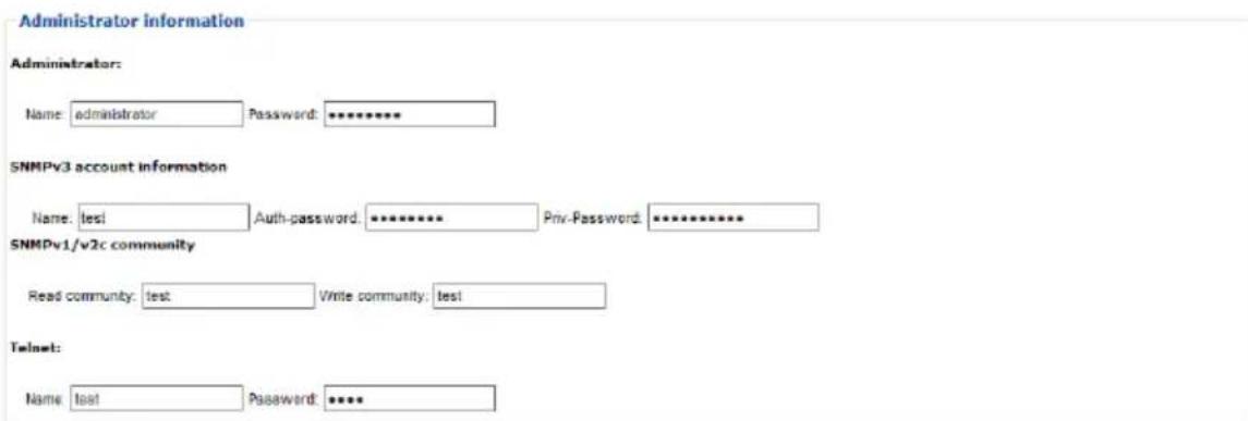
Administrator Information
This section is used to set the Administrator name and password. Only Administrators can view this section. For details, see Changing the Administrator Login, page 26.
SNMPv3 Account Information
- Enter values for Name, Auth-Password and Priv-Password for SNMPv3 authentication, if required.
SNMPv1/v2c Community
- Enter values Read community and Write community for SNMPv1/V2c authentication, if required.
Telnet
- Use the Name and Password fields to change the account used to login via Telnet sessions.
Click Save to save your settings.
User Information
To add a user, do the following:
- Select the Enable or Disable in the Management drop-down menu.
- Key in a name and password in the Name and Password fields.
- Set the outlet-by-outlet permissions of the user in the Outlet field.
- Click Save to save your settings.
Note: Values must be entered in both the Name and Password fields in order to enable an account.
The various options are explained in more detail in the following table:
| Field Description | ||
| Management The Management field allows you to Enable or Disable a user's account:◆ Enable – stores the user account (see User Information, page 43◆ Disable – disables the user account | ||
| Name From 1 to 16 characters are allowed depending on the Account Policy settings. See Account Policy, page 56. | ||
| Password From 1 to 16 characters are allowed depending on the Account Policy settings. See Account Policy, page 56. | ||
| Outlet This field allows you to set the outlet-by-outlet permissions of the user. Click on the user/port icon to cycle through the three permissions options, as follows: | ||
| Save Click this button to save your operation or changes | ||
Log
The Log tab keeps a record of transactions that take place on its installation, and stores up to 128 events at one time. The System Log page provides a powerful array of filters and functions that allow you to view and export the log file data, as well as be informed by email of specified events as they occur.
| No. | Date/Time | Category | Severity | User | Description |
| 001 | 2014-07-16 23:44:10 | Device | Information | administrator | Bank 1 name was changed by administrator. |
| 002 | 2014-07-18 23:43:52 | Device | Information | administrator | Bank 1 name was changed by administrator. |
| 003 | 2014-07-16 23:01:22 | Device | Information | Outlet 6 was turned OFF. | |
| 004 | 2014-07-18 23:01:21 | Device | Information | administrator | OFF command issued to Outlet 6 by administrator. |
| 005 | 2014-07-16 23:01:13 | Device | Information | Outlet 3 was turned OFF. | |
| 006 | 2014-07-18 23:01:12 | Device | Information | administrator | OFF command issued to Outlet 3 by administrator. |
| 007 | 2014-07-16 23:01:06 | Device | Information | Outlet 1 was turned OFF. | |
| 008 | 2014-07-18 23:01:05 | Device | Information | administrator | OFF command issued to Outlet 1 by administrator. |
| 009 | 2014-07-16 21:33:21 | User Management | Information | administrator | User (Username: ss) access rights were modified by administrator. |
| 010 | 2014-07-16 21:33:21 | User Management | Information | administrator | User (Username: dd) access rights were modified by administrator. |
| 011 | 2014-07-16 21:33:21 | User Management | Information | administrator | User (Username: lf) access rights were modified by administrator. |
| 012 | 2014-07-16 21:32:41 | User Management | Information | administrator | User (Username: ds) access rights were modified by administrator. |
| 013 | 2014-07-16 21:31:29 | Authentication | Information | administrator | administrator 19.3.41.62 logged in. |
| 014 | 2014-07-16 20:39:33 | Authentication | Information | administrator | administrator 19.3.52.74 logged out. |
| 015 | 2014-07-16 14:40:19 | Device | Information | administrator | Outlet 24 name was changed by administrator. |
| 016 | 2014-07-16 14:40:19 | Device | Information | administrator | Outlet 23 name was changed by administrator. |
| 017 | 2014-07-16 14:40:18 | Device | Information | administrator | Outlet 22 name was changed by administrator. |
The System Log Event List
- Clicking on a device in the Sidebar displays its log events in the main panel's log event list.
- Clicking the Refresh button brings the log list up to date with the latest events.
- The entry box to the right of the Refresh button lets you set the number of events to display per page. Simply key in the number of your choice.
-
The top right of the main panel shows the total number of pages in the log file, and what page you are currently viewing.
◆ The buttons on the bottom row function as follows: -
Clear – click to erase the contents of the log event list
- First Page – click to go to the first page of the log event list
- Previous Page – click to move to the previous page of the log event list
- Next Page – click to move to the next page of the log event list
- Last Page – click to move to the last page of the log event list
- Export Log – click to save the contents of the log event list to file.
Notification Settings
The Notification Settings page is used to specify which of the eco PDU's components will receive notification of a log event. When you click the Notification Settings menu item, a page similar to the one below appears:
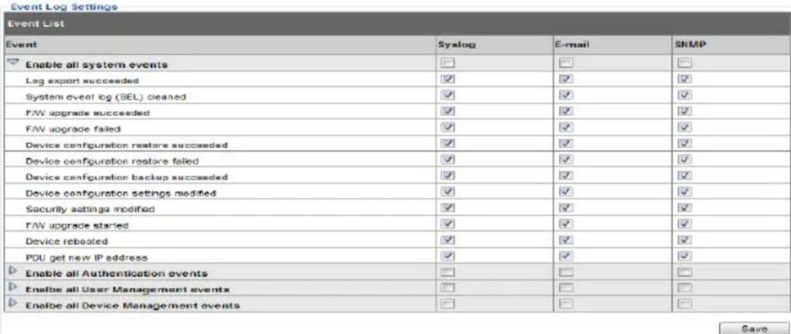
◆ The event categories are listed in the left column.
- When you first open the page, only the main category items appear. (Main category item rows have a gray background.)
Sub-category items are nested under the main category headings. Click the arrow in front of the main category headings to display the subcategory items. (Sub-category item rows have a white background.)
- Click the checkboxes under the column headings to select which component(s) will receive notification of the log events.
- Clicking on a main category heading's row automatically selects all the sub-category items nested below it.
If you only want to set notification for some of the sub-category events, don't put a check in the main category row. Instead, drop down the sub-category list, and only check the sub-category events you want.
- When you have finished making your setting choices, click Save. When a specified log event occurs, notification of that event will be sent to the selected component.
- Reset Digital Output: If an event has been triggered that changes the digital output sensor from Low to High, click this button to return the sensor to the Low state.
Setup
The Setup tab provides Device Configuration and Security settings. The Device Configuration page allows administrators to configure eco PDU system settings. The Security page controls access to the PDU.
Device Configuration
This page presents information about the selected device, as described in the following sections:
General
General
PDU Name :
PE8 Series
MAC Address :
00:04:A3:1E:FC:19
Firmware Version :
1.0.023 Ver
Rack Location name :
PE8 Series
| Item Meaning | |
| PDU Name This field | ld lets you give the device a unique name. Simply delete whatever is in the text box and key in the name of your choice.Click Save (located at the bottom of the page) to save the new name. |
| MAC Address This | item displays the eco PDU's MAC address. |
| Firmware Version | This item displays the current firmware version number. You can reference it to see if there are newer versions available on the NRGence website. |
| Rack Location Name | This field lets you give the rack location a unique name for easy reference. |
Service Ports
As a security measure, if a firewall is being used, the Administrator can specify the port numbers that the firewall will allow. If a port other than the default is used, users must specify the port number as part of the IP address when they log in. If an invalid port number (or no port number) is specified, the eco PDU will not be found.
Select whether to allow only secure browser logins, as show below:
Service Ports
Only HTTPS HTTP/HTTPS
HTTP: 80
HTTPS: 443
An explanation of the fields is given in the table below:
| Field Explanation |
| HTTP The port number for a browser login. The default is 80. |
| HTTPS The port number for a secure browser login. The default is 443. |
Note: 1. Valid entries for all of the Service Ports are from 1–65535.
-
The service ports cannot have the same value. You must set a different value for each one.
-
If there is no firewall (on an Intranet, for example), it doesn't matter what these numbers are set to, since they have no effect.
IPv4 Configuration
The PDU's IPv4 IP and DNS addresses (the traditional method of specifying IP addresses) can either be assigned dynamically (DHCP), or a fixed IP address can be specified.
IPv4 Configuration
Obtain IP address automatically [DHCP]
Set IP address manually [Fixed IP]
IP Address:
Subnet Mask:
Default Gateway:
Obtain DNS server address automatically
Set DNS server address manually
Preferred DNS Server:
Alternate DNS Server:
natural_image
Three horizontal gray bars with no text or symbols- For dynamic IP address assignment, select the Obtain IP address automatically radio button. (This is the default setting.)
- To specify a fixed IP address, select the Set IP address manually radio button and fill in the IP address with values appropriate for your network.
- For automatic DNS Server address assignment, select the Obtain DNS Server address automatically radio button.
- To specify the DNS Server address manually, select the Set DNS server address manually radio button, and fill in the addresses for the Preferred and Alternate DNS servers with values appropriate for your network.
Note: 1. If you choose Obtain IP address automatically, when the device starts up it waits to get its IP address from the DHCP server. If it hasn't obtained the address after one minute, it automatically reverts to its factory default IP address (192.168.0.60.)
-
If the device is on a network that uses DHCP to assign network addresses, and you need to ascertain its IP address, see IP Address Determination, page 89, for information.
-
Specifying the Alternate DNS Server address is optional.
Event Notification
The Event Notification section is divided into three sections: SMTP Server; SNMP Trap Receivers; and Syslog Server. Each section is described below.
SMTP Server
Event Notification
SMTP Server
√ Enable report from the following SMTP Server
SMTP Server:
192.168.0.78
SMTP Port Number :
25
My server requires authentication
Account Name:
test
Password:
●●●●
From:
test@aten.com
To:
test@aten.com
To have the eco PDU email reports from the SMTP server to you, do the following:
- Enable the Enable report from the following SMTP Server, and key in the IP address and Port number of your SMTP server.
- If your server requires authentication, put a check in the My server requires authentication checkbox.
- Key in the appropriate account information in the Account Name, Password, and From fields.
Note: Only one email address is allowed in the From fields, and it cannot exceed 64 characters.
- Key in the email address (addresses) of where you want the event reports sent to in the To field.
Note: If you are sending the report to more than one email address, separate the addresses with a semicolon. The total cannot exceed 256 characters.
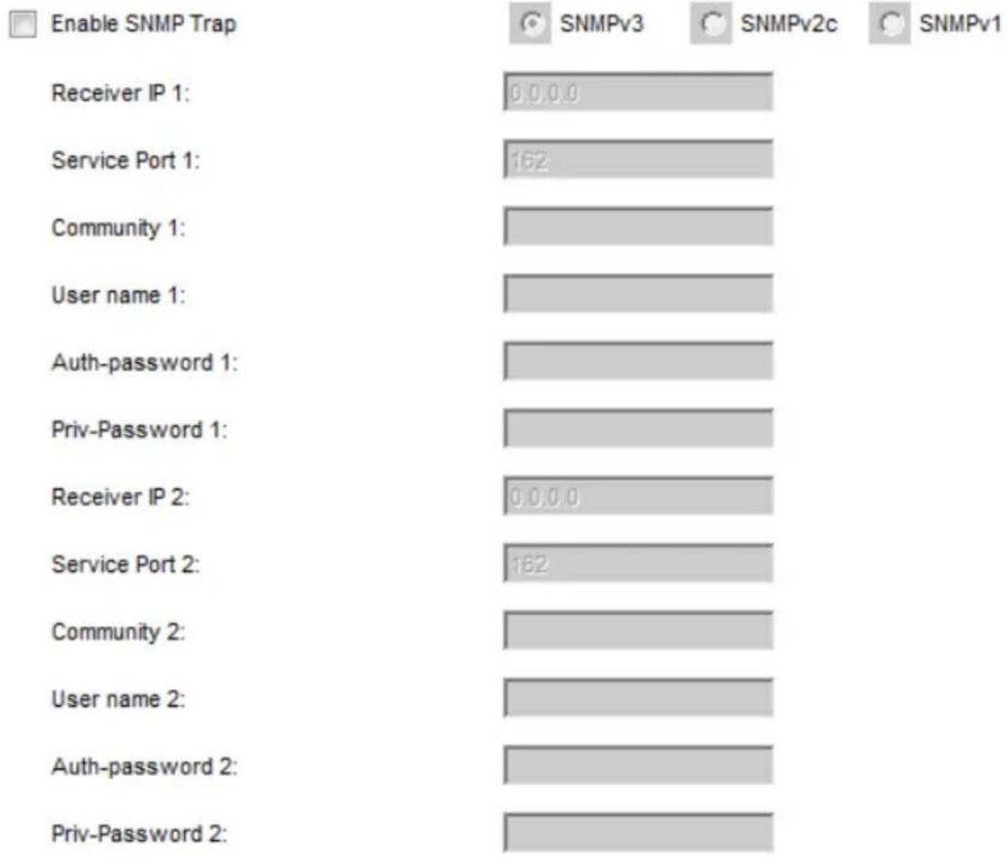
- SNMP Trap Receivers
SNMP Trap Receiver
bar
| Category | Enable SNMP Trap | | :--- | :--- | | Receiver IP 1: | 0,0,0,0 | | Service Port 1: | 162 | | Community 1: | | | User name 1: | | | Auth-password 1: | | | Priv-Password 1: | | | Receiver IP 2: | 0,0,0,0 | | Service Port 2: | 162 | | Community 2: | | | User name 2: | | | Auth-password 2: | | | Priv-Password 2: | |Up to four SNMP management stations can be specified. If you want to use SNMP trap notifications, do the following:
- Check Enable SNMP Trap.
- Select which version of SNMP you want to use.
- Key in the IP address(es) and the service port number(s) of the computer(s) to be notified of SNMP trap events. The valid port range is 1–65535. The default port number is 162.
Note: Make sure that the port number you specify here matches the port number used by the SNMP receiver computer.
-
Key in the community value(s) if required for the SNMP version.
-
Key in the auth/privacy password(s) that correspond to each of the stations.
Syslog Server
Syslog Server

Enable Syslog Server
Server IP:
Service Port:
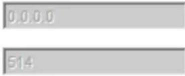
To record all the events that take place on eco PDU devices and write them to the eco PDU Syslog server, do the following:
-
Check Enable Syslog Server.
-
Key in the IP address and the port number of the Syslog server. The valid port range is 1-65535. The default port number is 514.
Date/Time
The Date/Time dialog page sets the eco PDU time parameters:
Date Time
Time Zone
(GMT-12:00) Eniwetok Kwajalein
Daylight Savings Time
Manual Input
Sync with PC
Network Time
Enable auto adjustment
AU | ntp1.cs.mu.OZ.AU
Preferred custom server IP:
0.0.0.0
Alternate time server:
AU | ntp1.cs.mu.OZ.AU
Alternate custom server IP:
0,0,0,0
Adjust time everydays
1
Adjust Time Now
Time Zone
- To establish the time zone that the eco PDU is located in, drop down the Time Zone list and choose the city that most closely corresponds to where it is at.
- If your country or region employs Daylight Saving Time (Summer Time), check the corresponding checkbox.
Manual Input
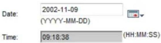
Use this section to specify the eco PDU's date and time manually.
- Click the calendar icon and click the calendar entry for the date.
- Key the time into the Time field, using the HH:MM:SS (hours, minutes, seconds) format.
Note: This section is only enabled when auto adjustment (in the Network Time section) is disabled (the checkbox is unchecked).
As an alternative to specifying the date and time by entering them into the date and time fields, you can click to put a check in the Sync with PC checkbox, in which case the eco PDU will take its date and time settings from the locally connected PC.
Network Time
To have the time automatically synchronized to a network time server, do the following:
- Check the Enable auto adjustment checkbox.
- Drop down the time server list to select your preferred time server
- or -
Check the Preferred custom server IP checkbox, and key in the IP address of the time server of your choice.
-
If you want to configure an alternate time server, check the Alternate time server checkbox, and repeat step 2 for the alternate time server entries.
-
Key in your choice for the number of days between synchronization procedures.
Finishing Up
When you have finished making your settings on this page, click Save.
After you have saved your changes, if you want to synchronize immediately, click Adjust Time Now.
Security
The Security page controls access to the eco PDU device.
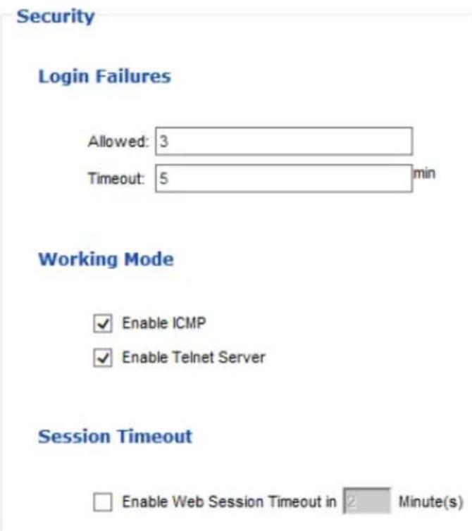
Login Failures
- Allowed sets the number of consecutive failed login attempts that are permitted from a remote user.
- Timeout sets the amount of time a remote user must wait before attempting to login again after exceeding the number of allowed failures.
Working Mode
- If Enable ICMP is checked, the eco PDU device can be pinged. If it is not enabled, the device cannot be pinged. The default is Enabled.
- If Enable Telnet Server is checked, the PDU is accessible via a Telnet sessions using the Telnet username and password (see Telnet, page 43)
Session Timeout
- If Enable Web Session Timeout in is checked, a user's web session will logout due to inactivity after the number of Minute(s) entered (1–5) is surpassed.
When you have finished making your settings on this page, click Save.
Account Policy
The Account Policy section governs policies in regard to usernames and passwords.
Account Policy
Minimum Username Length: 6
Minimum Password Length: 6
Password Must Contain At Least:
One Upper Case
One Lower Case
One Number
Disable Duplicate Login
Check a policy and enter the required information in the appropriate fields.
| Item Description | |
| Minimum Username Length Sets | the minimum number of characters required for a username. Acceptable values are from 1–16. |
| Minimum Password Length Sets | the minimum number of characters required for a password. Acceptable values are from 1–16. |
| Password Must Contain At Least | Checking any of these items requires users to include at least one of the specified items in their password.Note: This policy does not affect existing user accounts. Only new user accounts created after this policy has been enabled, and users required to change their passwords are affected. |
| Disable Duplicate Login Check this | to prevent users from logging in with the same account at the same time. |
Login String / IP Filter / Mac Filter
Login String/IP Filter/MAC Filter
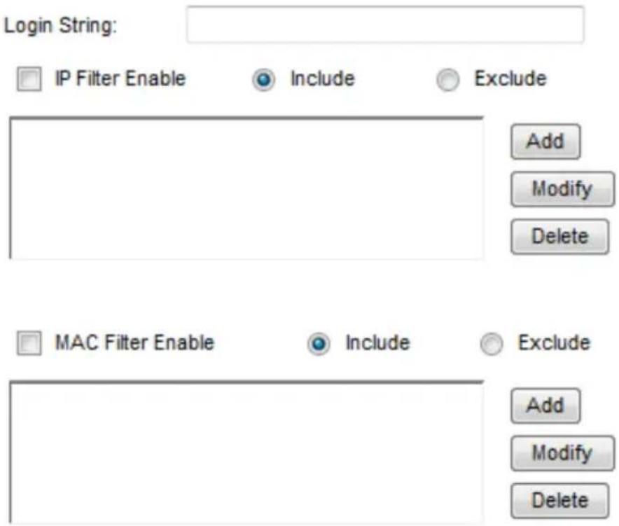
■ Login String
The Login String entry field is used to specify a login string (in addition to the IP address) that users must include when accessing the eco PDU device with a browser. For example:
192.168.0.126/abcdefg
◆ The following characters are allowed:
0-9 a-z A-Z \~! @ \$ * () _ ' ,
◆ The following characters are not allowed:
& ^ { } ' ' < > | " % " : / ? # \ [Space] + - = [ ] ;
Compound characters (É Ç ñ ... etc.)
Note: 1. There must be a forward slash between the IP address and the string.
- If no login string is specified here, anyone will be able to access the eco PDU device login page using the IP address alone. This makes your installation less secure.
For security purposes, we recommend that you change this string occasionally.
■ IP Filter / MAC Filter
If any filters have been configured, they appear in the IP Filter and/or MAC Filter list boxes.
IP and MAC Filters control access to the eco PDU based on the IP and/or MAC addresses of the client computers attempting to connect. A maximum of 5 IP filters and 5 MAC filters are allowed.
To enable IP and/or MAC filtering, click to put a check mark in the IP Filter Enable and/or MAC Filter Enable checkbox.
- If the include button is checked, all the addresses within the filter range are allowed access; all other addresses are denied access.
- If the exclude button is checked, all the addresses within the filter range are denied access; all other addresses are allowed access.
Adding Filters
To add an IP filter, do the following:
- Click Add. A dialog box similar to the one below appears:
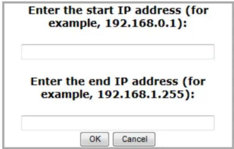
-
Specify the start filter address in the dialog box (for example, 192.168.0.200), then click OK.
-
To filter a single IP address, key in the same address as the start IP. To filter a continuous range of addresses, key in the end number of the range (for example, 192.168.0.225).
-
After filling in the address, click OK.
Repeat these steps for any additional IP addresses you want to filter.
To add a MAC filter, do the following:
- Click Add. A dialog box similar to the one below appears:
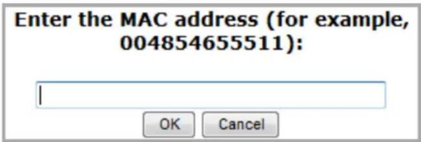
- Specify the MAC address in the dialog box (for example, 001074670000), then click OK.
Repeat these steps for any additional MAC addresses you want to filter.
IP Filter / MAC Filter Conflict
If there is a conflict between an IP filter and a MAC filter – for example, where a computer's IP address is allowed by the IP filter but its MAC address is excluded by the MAC filter – then that computer's access is blocked.
In other words, if either filter blocks a computer, then the computer is blocked, no matter what the other filter is set to.
Modifying Filters
To modify a filter, select it in the IP Filter or MAC Filter list box and click Modify. The Modify dialog box is similar to the Add dialog box. When it comes up, simply delete the old address(es) and replace it with the new one(s).
Deleting Filters
To delete a filter, select it in the IP Filter or MAC Filter list box and click Delete.
Authentication & Authorization
The Authentication & Authorization page is used to set up login authentication and authorization management from external sources.
Authentication & Authorization
RADIUS Settings

Enable RADIUS
Preferred RADIUS Server IP:
Preferred RADIUS Service Port:
Alternate RADIUS Server IP:
Alternate RADIUS Server Port:
Timeout:
Retries:
Shared Secret (at least 6 characters):
0,0,0,0
1812
0,0,0,0
1645
1
D
F
sec
RADIUS Settings
To allow authentication and authorization for the eco PDU device through a RADIUS server, do the following:
- Check Enable.
-
Fill in the IP addresses and service port numbers for the Preferred and Alternate RADIUS servers. The default port number for the Preferred server is 1812; the default port number for the Alternate server is 1645.
-
On the RADIUS server, set the entry for each user as follows:
su/administrator or su/user
Where xxxx represents the Username given to the user when the account was created on the eco PDU device. The user's access rights are the ones assigned for the eco PDU device, as well. (See User Information, page 43.)
Note: su/user supports view ports only; su/administrator supports all eco PDU functions.
Private Certificate
When logging in over a secure (SSL) connection, a signed certificate is used to verify that the user is logging in to the intended site. For enhanced security, the Private Certificate section allows you to use your own private encryption key and signed certificate, rather than the default ATEN certificate.
Private Certificate
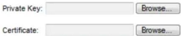

There are two methods for establishing your private certificate: generating a self-signed certificate; and importing a third-party certificate authority (CA) signed certificate.
Generating a Self-Signed Certificate
If you wish to create your own self-signed certificate, a free utility – openssl.exe – is available for download over the web.
Obtaining a CA Signed SSL Server Certificate
For the greatest security, we recommend using a third party certificate authority (CA) signed certificate. To obtain a third party signed certificate, go to a CA (Certificate Authority) website to apply for an SSL certificate. After the CA sends you the certificate and private encryption key, save them to a convenient location on your computer.
(Continues on next page.)
Importing the Private Certificate
To import the private certificate, do the following:
- Click Browse to the right of Private Key; browse to where your private encryption key file is located; and select it.
- Click Browse to the right of Certificate; browse to where your certificate file is located; and select it.
- Click Upload to complete the procedure.
Note: 1. Clicking Restore Default returns the device to using the default ATEN certificate.
2. Both the private encryption key and the signed certificate must be imported at the same time.
When you have finished making your settings on this page, click Save.
PDU
The PDU tab is used to upgrade the eco PDU's firmware, and to backup and restore the device's configuration settings.
Firmware File
When you click the Maintenance tab, the display opens with the Firmware Upgrade menu page, which looks similar to the one below:
![Firmware File ✓ Check Main Firmware Version Energy Box Name F/W Version [PE1108A] F/W Ver:1.1.133 Filename: Browse... Upgrade Backup Password: Save Restore Filename: Browse... Password: Restore](/content/2026/05/957546/images/26d4651798fff18de1cd6feb0dcae293f9d856bf14fe4a1450164e5e60a6672b.jpg)
A description of the items shown in this panel are given in the table, below:
| Item Description | |
| Check Main Firmware Version | If you enable Check Main Firmware Version, the eco PDU's current firmware level is compared with that of the upgrade file. If the current version is equal to or higher than the upgrade version, a popup message appears, to inform you of the situation and stops the upgrade procedure. |
| Name Lists all of the | eco PDU devices. Click to put a check in the checkbox of the device's whose firmware you want to upgrade. |
| F/W Version Displays | the eco PDU's current firmware version. |
| Filename As new versions | versions of the firmware become available, they are posted on our website and can be downloaded to a convenient location on your computer. Click the Browse button to select the downloaded upgrade file. |
| Upgrade Click this | button to upgrade the firmware of the selected devices. |
■ Upgrading the Firmware
To upgrade the firmware refer to the screenshot on the preceding page, and do the following:
- Go to our website and download the new firmware file to a convenient location on your computer.
- Click the Browse button; navigate to where the firmware file is located and select it.
-
Click Upgrade to start the upgrade procedure.
-
If you enabled Check Main Firmware Version the current firmware level is compared with that of the upgrade file. If the current version is equal to or higher than the upgrade version, a popup message appears, to inform you of the situation and stops the upgrade procedure.
- If you didn't enable Check Main Firmware Version, the upgrade file is installed without checking what its level is.
-
Once the upgrade completes successfully, the switch resets itself.
-
Log in again, and check the firmware version to be sure it is the new one.
■ Firmware Upgrade Recovery
Should the eco PDU's firmware upgrade procedure fail, and the device becomes unusable, the following firmware upgrade recovery procedure will resolve the problem:
- Power off the device.
- Press and hold the reset button (see page 7).
- While holding the Reset Switch in, power the switch back on.
This causes the switch to use the original factory installed main firmware version. Once the switch is operational, you can try upgrading the main firmware again.
Backup/Restore
Selecting Backup/Restore on the menu bar gives you the ability to back up the switch's configuration and user profile information:
Backup
To backup the device's settings do the following:
- In the Password field, key in a password for the file.
Note: Entering a password is optional. If you do enter a password, make a note of it, since you will need it to be able to restore the file.
- Click Save.
- When the browser asks what you want to do with the file, select Save to disk; then save it in a convenient location.
Restore
To restore a previous backup, do the following:
- Click Browse; navigate to the file and select it.
Note: If you renamed the file, you can leave the new name. There is no need to return it to its original name.
- In the Password field, key in the same password that you used to save the file.
Note: If you did not set a password when you created the backup file, you can omit this step.
- Select as many of the options that are presented as you wish to restore.
- Click Restore.
After the file is restored, a message appears to inform you that the procedure succeeded.
This Page Intentionally Left Blank
Remote Terminal Operations
With ATEN PE6108AV / PE6208AV / PE8208AV you can log in remotely from a computer using Telnet or via the built-in bi-directional RS-232 serial interface that allows system control through a high-end controller or PC.
Telnet
Telnet is a program that connects to a device over a network to provide text-based management and control. Telnet provides some of the same management features found in the eco PDU's web GUI. You can reference the eco PDU's web GUI functions by downloading the user manual from our website (www.aten.com). This can help you as you work your way through the text-based commands used to control the eco PDU that are discussed in this guide.
Telnet is available on all NRGence ^™ eco PDUs installed with the latest firmware. You can log in to the eco PDU via Telnet from any computer connected to the same network.
Setup
Log in to the eco PDU's web GUI, go to the Setup tab and click Security from the menu bar. Under Working Mode, check Enable Telnet Server and then click Save at the bottom of the page.
![NRGence PE8208AV Device Configuration | Security Help PE8208AV [01] [02] [03] [04] [05] [06] [07] [08] Security Login Failures Allowed: 3 Timeout: 5 min Working Mode Enable ICMP Enable Telnet Server Session Timeout](/content/2026/05/957546/images/70ba92204fdc66cf9c2fcfbfff11905df0cb64600b7cd2a4543f56e3904a43d2.jpg)
Note: If the Enable Telnet Server option is not available, please download the latest firmware from our website.
Logging In
To log in to the eco PDU via Telnet, do the following:
- On your computer, open the start menu and select Run. Type: cmd
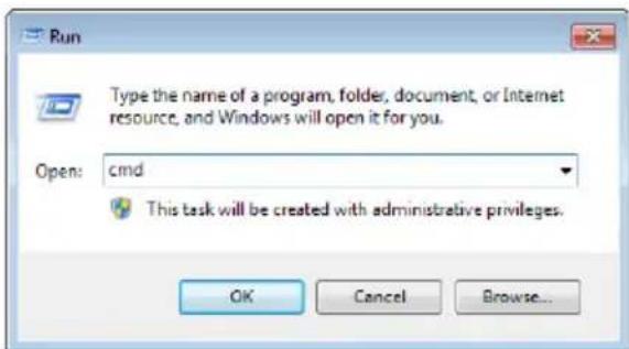
Click OK.
- At the command prompt, key in telnet and the IP Address of the PDU, as follows:
telnet [IP Address]
- Press Enter. The login screen appears:
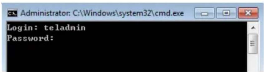
- At the login prompt, enter Username: teladmin; and Password: telpwd.
Note: The Telnet username and password can be configured on the User tab of the eco PDU's web GUI.
- When the Telnet session is established, Logged in successfully appears along with the command line prompt:
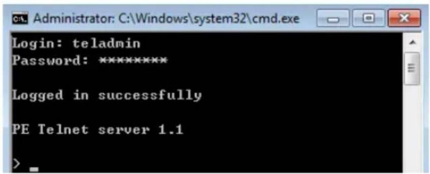
RS-232 Serial Control
This section provides the serial control settings and PIN assignments used to configure the RS-232 Serial Port.
RS232 Pin Assignment
| Pin Description | Pin Description | ||
| 1 Not connected 6 | Not connected | ||
| 2 RXD 7 | Not connected | ||
| 3 TXD 8 | Not connected | ||
| 4 Not connected 9 | Not connected | ||
| 5 | GND |
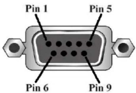
Configuring the Serial Port
The controller's serial port should be configured as follows:
| RS-232 Serial Control Protocol Settings | |
| Baud Rate 115200 | (Default) |
| Data Bit 8 bits | |
| Parity None | |
| Stop Bit 1 Bit | |
| Flow Control None | |
Commands
Use the Telnet and RS-232 text commands to view and configure the eco PDU as described in each section. The text-based command line provides some of the same functions found under the Energy tab of the eco PDU's web-based GUI. Commands to view and configure the eco PDU are provide in the following sections. You can reference information provided in the user manual for the functions as you use the commands.
Verification
After sending an incorrect command, a verification message appears at the end of the command line.
- Invalid command or exceed max command length - the command has the wrong format and/or values. Try typing in the command string again using the correct format and/or values.
Read Outlet Status
The Read Outlet Status command allows you to view the power status of an outlet on the eco PDU.
The formula for Read Outlet Status commands is as follows:
$$ \text { Command } + \text { Outlet } + \text { Number } + \text { Return String } + [ \text { Enter } ] $$
- For example, if you want to read the status of outlet 01 with a simple return string, type the following:
$$ \text { read status o01 simple [Enter] } $$
- For example, if you want to read the status of outlet 12 with a format return string, type the following:
$$ \text { read status o12 format [Enter] } $$
The following tables show the possible values for the Read Outlet Status commands:
| Command Description | |
| read status Read status command | |
| Outlet Description | |
| o Outlet command | |
| xx PDU Outlet numberxx: Outlet on PDUExample: o02 | |
| Return String Description | |
| simple Return | simple string status |
| format Return | format string status |
The following table lists the available Read Outlet Status commands:
| Command Outlet | Return String | Enter Description |
| read status of XX simple | [Enter] | Read the status of outlet XX with a simple return string.XX: Outlet number |
| read status of XX format | [Enter] | Read the status of outlet XX with a format return string.XX: Outlet number |
Note: 1. Each command string can be separated with a space.
- The Return String command string can be skipped and format will be used by default.
Switch Outlet Status
The Switch Outlet Status command allows you to change the power status of an outlet on the eco PDU.
The formula for Switch Outlet Status commands is as follows:
$$ \text { Command } + \text { Outlet } + \text { Number } + \text { Control } + \text { Option } + [ \text { Enter } ] $$
- For example, if you want to switch off outlet 04 immediately, type the following:
$$ \text { sw o04 off imme [Enter] } $$
- For example, if you want to switch on outlet 12 with the time delay set for the outlet, type the following:
$$ \text { sw o12 on delay [Enter] } $$
- For example, if you want to reboot outlet 08, type the following:
$$ \text { sw o08 reboot [Enter] } $$
The following tables show the possible values for the Switch Outlet Status commands:
| Command Description | |
| sw Switch outlet status command | |
| Outlet Description | |
| o Outlet command | |
| xx PDU outlet number | |
| Control Description | |
| on Switch outlet on | |
| off Switch outlet off | |
| reboot Switch outlet off and then switch outlet on | |
| Option Description | |
| imme Switch outlet status immediately | |
| delay Switch outlet status with time delay set for the outlet |
The following table lists the available Switch Outlet Status commands:
| Command | Outlet | Control | Option | Enter | Description |
| sw oXX on imme | delay | [Enter] S | witch outlet XX on with optionXX: Outlet number | ||
| sw oXX off imme | delay | [Enter] S | witch outlet XX off with optionXX: Outlet number | ||
| sw oXX reboot [Enter] Read the status of outlet XX | XX: Outlet number | ||||
Note: 1. Each command string can be separated with a space.
- The Option command string can be skipped and delay will be used by default.
Read Power Value
The Read Power Value command allows you to view the power measurement values of the eco PDU, Bank or Outlet.
The formula for Read Power Value commands is as follows:
$$ \begin{array}{l} \text {Command + Target + Number + Measurement + Return String +} \ \text {[ E n t e r ]} \end{array} $$
- For example, if you want to read the voltage measurement of outlet 12 with a simple return string, type the following:
$$ \text { read meter olt o12 volt simple [Enter] } $$
- For example, if you want to read the power dissipation measurement of bank 02 with a format return string, type the following:
$$ \text { read meter bnk o02 pd format [Enter] } $$
- For example, if you want to read the voltage frequency measurement of the PDU with a simple return string, type the following:
$$ \text { read meter dev freq simple } [ \text { Enter } ] $$
The following tables show the possible values for the Read Power Value commands:
| Command Description | |
| read meter Read power value command | |
| Target Description | |
| dev Get value from PDU | |
| bnk Get value from bank | |
| olt Get value from outlet | |
| Number Description | |
| o Target number command | |
| xx Bank or outlet numberxx: Bank or Outlet on PDUExample: o02 | |
| Measurement Description | |
| curr Read current measurement | |
| volt Read voltage measurement | |
| pow Read power measurement | |
| Measurement Description | |
| pd Read power dissipation measurement | |
| pf Read power factor measurement | |
| freq Read voltage frequency measurement | |
| Return String Description | |
| simple Return simple string measurement | |
| format Return format string measurement |
The following table lists the available Read Power Value commands:
| Command | Target | Number | Measurement | Return String | Enter | Description |
| read meter | dev curr | voltpowpdpffreq | simple format | [Enter] | Read PDU measurement with return string | |
| read meter | bnk oXX curr | voltpowpdpffreq | simple format | [Enter] | Read bank XX measurement with return stringXX: Bank number | |
| read meter | olt | oXX | currvoltpowpdpffreq | simple format | [Enter] | Read outlet XX measurement with return stringXX: Outlet number |
Note: 1. Each command string can be separated with a space.
- The Return String command string can be skipped and format will be used by default.
Read Environmental Value
The Read Environmental Value command allows you to view measurements from the eco PDU's environmental sensors.
The formula for Read Environmental Value commands is as follows:
$$ \text { Command } + \text { Sensor } + \text { Number } + \text { Return String } + [ \text { Enter } ] $$
- For example, if you want to read environmental sensor 02 with a simple return string, type the following:
$$ \text { read sensor o02 simple [Enter] } $$
- For example, if you want to read environmental sensor 01 with a format return sting, type the following:
$$ \text { read sensor o01 format [Enter] } $$
The following tables show the possible values for the Read Environmental Value commands:
| Command Description | |
| read sensor Read environmental value command | |
| Sensor Description | |
| o Environmental sensor command | |
| xx Sensor number | xx: Environmental sensor on PDU (01~04)Example: o02 |
| Return String Description | |
| simple Return | simple string measurement |
| format Return | format string measurement |
The following table lists the available Read Environmental Value commands:
| Command Sensor | Return String | Enter Description |
| read sensor of XX simple format | [Enter] R | read environmental sensor XX with return string option |
Note: 1. Each command string can be separated with a space.
- The Return String command string can be skipped and format will be used by default.
Close Telnet Session
The Close Telnet Session command allows you to disconnect the telnet session from the eco PDU.
The formula for the Close Telnet Session command is as follows:
$$ \text { Command } + [ \text { Enter } ] $$
- For example, if you want to disconnect the telnet session, type the following:
$$ \text { quit } [ \text { Enter } ] $$
The following table shows the value for the Close Telnet Session command:
| Command Description |
| quit Close telnet session command |
The following table lists the Close Telnet Session command:
| Command Enter Description | ||
| quit [Enter] | Disconnect telnet session with eco PDU | |
Safety Instructions
General
- This product is for indoor use only.
- Read all of these instructions. Save them for future reference.
◆ Follow all warnings and instructions marked on the device. - Do not place the device on any unstable surface (cart, stand, table, etc.). If the device falls, serious damage will result.
♦ Do not use the device near water. - Do not place the device near, or over, radiators or heat registers.
- The device cabinet is provided with slots and openings to allow for adequate ventilation. To ensure reliable operation, and to protect against overheating, these openings must never be blocked or covered.
- The device should never be placed on a soft surface (bed, sofa, rug, etc.) as this will block its ventilation openings. Likewise, the device should not be placed in a built-in enclosure unless adequate ventilation has been provided.
- Never spill liquid of any kind on the device.
- Avoid circuit overloads. Before connecting equipment to a circuit, know the power supply’s limit and never exceed it. Always review the electrical specifications of a circuit to ensure that you are not creating a dangerous condition or that one doesn’t already exist. Circuit overloads can cause a fire and destroy equipment.
- Unplug the device from the wall outlet before cleaning. Do not use liquid or aerosol cleaners. Use a damp cloth for cleaning.
- The device should be operated from the type of power source indicated on the marking label. If you are not sure of the type of power available, consult your dealer or local power company.
- To prevent damage to your installation it is important that all devices are properly grounded.
- The device is equipped with a 3-wire grounding type plug. This is a safety feature. If you are unable to insert the plug into the outlet, contact your electrician to replace your obsolete outlet. Do not attempt to defeat the
purpose of the grounding-type plug. Always follow your local/national wiring codes.
If an extension cord is used with this device, make sure that the total of the ampere ratings of all products used on this cord does not exceed the extension cord's ampere rating. Make sure that the total of all products plugged into the wall outlet does not exceed 15 ampere.
- The equipment should be installed near the wall socket outlet and the disconnect device (appliance coupler) should be readily accessible.
- Do not allow anything to rest on the power cord or cables. Route the power cord and cables so that they cannot be stepped on or tripped over.
- To help protect your system from sudden, transient increases and decreases in electrical power, use a surge suppressor, line conditioner, or uninterruptible power supply (UPS).
- Position system cables and power cables carefully; Be sure that nothing rests on any cables.
- When connecting or disconnecting power to hot pluggable power supplies, observe the following guidelines:
- Install the power supply before connecting the power cable to the power supply.
◆ Unplug the power cable before removing the power supply. -
If the system has multiple sources of power, disconnect power from the system by unplugging all power cables from the power supplies.
-
Never push objects of any kind into or through cabinet slots. They may touch dangerous voltage points or short out parts resulting in a risk of fire or electrical shock.
- Do not attempt to service the device yourself. Refer all servicing to qualified service personnel.
- If the following conditions occur, unplug the device from the wall outlet and bring it to qualified service personnel for repair.
◆ The power cord or plug has become damaged or frayed.
◆ Liquid has been spilled into the device.
- The device has been exposed to rain or water.
- The device has been dropped, or the cabinet has been damaged.
- The device exhibits a distinct change in performance, indicating a need for service.
- The device does not operate normally when the operating instructions are followed.
- Only adjust those controls that are covered in the operating instructions. Improper adjustment of other controls may result in damage that will require extensive work by a qualified technician to repair.
- Do not connect the RJ-11 connector marked “Sensor” to a public telecommunication network.
- Before working on the rack, make sure that the stabilizers are secured to the rack, extended to the floor, and that the full weight of the rack rests on the floor. Install front and side stabilizers on a single rack or front stabilizers for joined multiple racks before working on the rack.
- Always load the rack from the bottom up, and load the heaviest item in the rack first.
Make sure that the rack is level and stable before extending a device from the rack. - Use caution when pressing the device rail release latches and sliding a device into or out of a rack; the slide rails can pinch your fingers.
- After a device is inserted into the rack, carefully extend the rail into a locking position, and then slide the device into the rack.
- Do not overload the AC supply branch circuit that provides power to the rack. The total rack load should not exceed 80 percent of the branch circuit rating.
- Make sure that all equipment used on the rack – including power strips and other electrical connectors – is properly grounded.
- Ensure that proper airflow is provided to devices in the rack.
- Ensure that the operating ambient temperature of the rack environment does not exceed the maximum ambient temperature specified for the equipment by the manufacturer
- Do not step on or stand on any device when servicing other devices in a rack.
The eco PDU's Main Power Cord
Use the power cord supplied with this package. If it becomes necessary to replace the cord supplied with this package, be sure to use a cord of at least the same standard as the one provided.
Securing the Power Cables
To secure the cables in the eco PDU's power outlets, use only the ATEN Lok-U-Plug cable holders that have been specifically designed to work with the eco PDU. Using any other kind of cable securing device could be highly dangerous. Please contact your ATEN dealer for information about ATEN Lok-U-Plugs.
Montage sur bâti
- For online technical support – including troubleshooting, documentation, and software updates: http://eservice.aten.com
- For telephone support, see Telephone Support, page vi
North America
| Email Support support@aten-usa.com | ||
| Online Technical Support | Troubleshooting Documentation Software Updates | http://eservice.aten.com |
| Telephone Support 1-888-999-ATEN | ext 49881-949-428-1111 | |
When you contact us, please have the following information ready beforehand:
◆ Product model number, serial number, and date of purchase.
- Your computer configuration, including operating system, revision level, expansion cards, and software.
◆ Any error messages displayed at the time the error occurred.
- The sequence of operations that led up to the error.
◆ Any other information you feel may be of help.
IP Address Determination
If you are an administrator logging in for the first time, you need to access the eco PDU in order to give it an IP address that users can connect to. There are two methods to choose from. In each case, your client computer must be on the same network segment as the eco PDU. After you have connected and logged in you can give the device its fixed network address. (See Notification Settings, page 46.)
Method 1:
For computers running Windows, an IP address can be determined and/or assigned with the IP Installer utility. The utility can be obtained from the Download area of our web site or from the software CD. Look under Driver/SW, and the model of your device. After downloading the utility to your computer, do the following:
- Unzip the contents of IPInstaller.zip to a directory on your hard drive.
- Go to the directory that you unzipped the IPInstaller program to and run IPInstaller.exe. A dialog box similar to the one below appears:
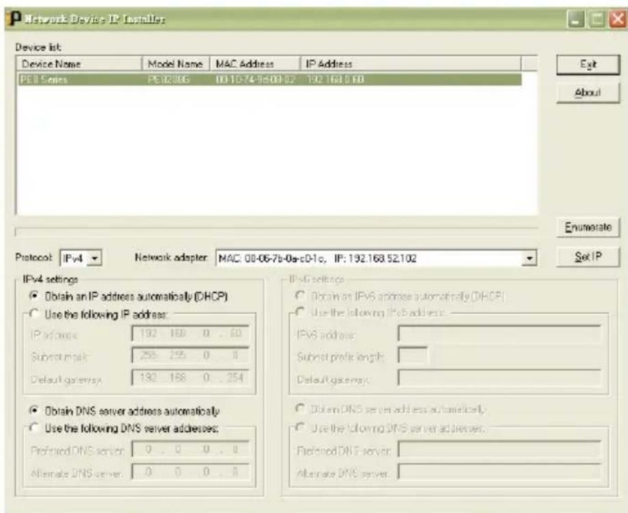
(Continues on next page.)
(Continued from previous page.)
- Select the device in the Device List.
Note: 1. If the list is empty, or your device doesn't appear, click Enumerate to refresh the Device List.
-
If there is more than one device in the list, use the MAC address to pick the one you want. The eco PDU's MAC address is located on its bottom panel.
-
Select either Obtain an IP address automatically (DHCP), or Specify an IP address. If you chose the latter, fill the IP Address, Subnet Mask, and Gateway fields with the information appropriate to your network.
- Click Set IP.
- After the IP address shows up in the Device List, click Exit to end the program.
Method 2:
- Set your computer's IP address to 192.168.0.XXX Where XXX represents any number or numbers except 60. (192.168.0.60) is the default address of the eco PDU.)
- Specify the device's default IP address (192.168.0.60) in your browser, and you will be able to connect.
- Assign a fixed IP address for the device (see IPv4 Configuration, page 49), that is suitable for the network segment that it resides on.
- After you log out, reset your computer's IP address to its original value.
- Once you have logged in, go to Network Settings to set up the permanent IP environment (see IPv4 Configuration, page 49).
Method 3:
NRGence eco DC allows you to determine/assign an IP address in order to configure a PDU device and monitor power status of the equipment connected to it. NRGence eco DC can be obtained from the Download area of the ATEN web site.
Specifications
PE6108AVA
| Function PE6108AVA | |
| Electrical | |
| Nominal Input Voltage 100 - 120 V AC | |
| Maximum Input Current 15 A (Max), 12 A (UL de-rated) | |
| Frequency 50 - 60 Hz | |
| Input Connection For A/J Plug: NEMA 5-15P | |
| Input Power 1800 V A (Max),1440 V A (UL de-rated) | |
| Outlet Type Total: 8 x NEMA 5-15R | |
| Nominal Output Voltage 100 - 120V AC | |
| Maximum Output Current (Outlet) | NEMA 5-15R: 15 A (Max) 12 A (UL de-rated) |
| Maximum Output Current (Bank) | 15 A (Max) 12 A (UL de-rated) |
| Maximum Output Current (Total) | 15 A (Max) 12 A (UL de-rated) |
| Metering Per Bank Level Current | Voltage, VA, PF and KWh Monitoring |
| Outlet Switching Yes | |
| Environment Sensor Ports 2 | |
| Metering Accuracy Voltage range: 100 V AC - 250 V AC +/- 1%Power range: 100 W - 5000 W +/- 2%Current range: 0.1 A - 1 A +/- 0.1 A, 1 A - 20 A +/- 1% | |
| Communication | |
| 10/100 Mbps | 1 x RJ-45 |
| RS-232 | 1 x DB-9 |
| Switches | |
| Power | Yes |
| Physical Properties | |
| Dimensions(L x W x H) | 43.24 x 26.73 x 4.40 cm(17.02 x 10.52 x 1.73 in.) |
| Weight | 3.70 kg (8.15 lb) |
| Power Cord Length | 3 m |
| Environmental | |
| Temperature (Operating / Storage) | 0 - 45 °C / -20 - 60 °C |
| Humidity (Operating & Storage) | 0-80% RH, Non-Condensing |
| Function | PE6108AVA |
| Compliance | |
| EMC Verification FCC, J55032 | |
| Safety Verification PSE | |
PE6208AVA / PE6208AVB / PE6208AVG / PE6208AVX
| Function | PE6208AVA | PE6208AVB | PE6208AVG | PE6208AVX |
| Electrical | ||||
| Nominal Input Voltage | 100 - 120 V AC 100 | - 240 V AC 100 - 240 V AC 100 - 240 V AC | ||
| Maximum Input Current | 20 A (Max), 16 A (UL de-rated) | 20 A (Max), 16 A (UL de-rated) | 16 A (Max) 16 A | |
| Frequency 50 - 60 Hz | ||||
| Input Connection AV | J:NEMA L5-20P A2/J2: NEMA 5-20P | NEMA 6-20P IEC | 60320 C20 Terminal | Block(3P) |
| Input Power 2400 V | A (Max), 1920 V A (UL de-rated) | 4600 V A (Max), 3680 V A (UL de-rated) | 3680 V A (Max) | 800 V A (Max) |
| Outlet Type | Total: 8 x NEMA 5-20R | Total: 8 x IEC60320 C13 | Total: 8 x IEC60320 C13 | Total: 8 x Terminal Block (3P) |
| Nominal Output Voltage | 100 - 120 V AC 100 | - 240 V AC 100 - 240 V AC 100 - 240 V AC | ||
| Maximum Output Current (Outlet) | NEMA 5-20R: 20 A (Max) 16 A (UL de-rated) | C13: 15 A (Max) 12 A (UL de-rated) | C13: 10A | 16 A (Max) |
| Maximum Output Current (Bank) | 20 A (Max) 16 A (UL de-rated) | 20 A (Max) 16 A (UL de-rated) | 16 A (Max) | 16 A (Max) |
| Maximum Output Current (Total) | 20 A (Max) 16 A (UL de-rated) | 20 A (Max) 16 A (UL de-rated) | 16 A (Max) | 16 A (Max) |
| Metering | Per Bank Level Current, Voltage, VA, PF and KWh Monitoring | |||
| Outlet Switching | Yes | |||
| Environment Sensor Ports | 2 | |||
| Metering Accuracy | Voltage range: 100 V AC-250 V AC +/- 1%Power range: 100 W - 5000 W +/- 2%Current range: 0.1 A - 1 A +/- 0.1 A, 1 A - 20 A +/- 1% | |||
Communication
| Function PE6 | 208AVA PE6208AVB | PE6208AVG PE6208AVX | ||
| 10/100 Mbps 1 x RJ-45 | ||||
| RS-232 1 x DB-9 | ||||
| Switches | ||||
| Power Yes | ||||
| Physical Properties | ||||
| Dimensions(L x W x H) | 43.24 x 26.72 x 4.40 cm(17.02 x 10.52 x 1.73 in.) | |||
| Weight 3.76 kg (8.28 lb) | ||||
| Power Cord Length | 3 m 3 m 3 m | N.A. | ||
| Environmental | ||||
| Temperature(Operating / Storage) | 0 - 50 °C / -20 - 60°C | 0 - 50 °C / -20 - 60°C | 0 - 40 °C / -20 - 60°C | 0 - 50 °C / -20 - 60°C |
| Humidity(Operating & Storage) | 0-80% RH, Non-Condensing | |||
| Compliance | ||||
| EMC Verification F | CC, J55032 FCC Others by Request | CE-EMC, FCC,J55032 Others by Request | FCC, CE | |
| Safety Verification | PSE Others by Request | CE-LVD, Othersby Request | CE, LVD | |
PE6208AVJ Japan
(Continues on next page.)
| Function PE8208AVB PE8208AVG | |||
| Power Outlets | Direct 8 | ||
| Connectors Power Inlet 1 x IEC 60320 C20 | |||
| LEDs Current / IP 2-digit 7-segment (Yellow) | |||
PE8208AVJ Japan
(Continues on next page.)
If you are unable to perform an Administrator login (because the Username and Password information has become corrupted, or you have forgotten it, for example), you can clear the login information with the following procedure:
- Power off the eco PDU and remove its housing.
- Short the jumper labeled J4 (PIN1 and PIN2).
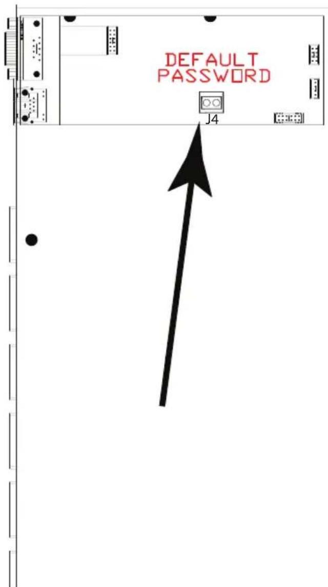
- Power on the eco PDU.
- When the 2-digit, 7-segment display shows "00", power off the switch.
- Remove the jumper cap from J4.
- Close the housing and start the eco PDU.
After you start, you can use the default Username and Password to log in.
Limited Warranty
ATEN warrants its hardware in the country of purchase against flaws in materials and workmanship for a Warranty Period of two [2] years (warranty period may vary in certain regions/countries) commencing on the date of original purchase. This warranty period includes the LCD panel of ATEN LCD KVM switches. Select products are warranted for an additional year (see A+ Warranty for further details). Cables and accessories are not covered by the Standard Warranty.
What is covered by the Limited Hardware Warranty
ATEN will provide a repair service, without charge, during the Warranty Period. If a product is detective, ATEN will, at its discretion, have the option to (1) repair said product with new or repaired components, or (2) replace the entire product with an identical product or with a similar product which fulfills the same function as the defective product. Replaced products assume the warranty of the original product for the remaining period or a period of 90 days, whichever is longer. When the products or components are replaced, the replacing articles shall become customer property and the replaced articles shall become the property of ATEN.
To learn more about our warranty policies, please visit our website: http://www.aten.com/global/en/legal/policies/warranty-policy/
Copyright © 2021 ATEN® International Co., Ltd.
Released: 2021-08-11
ATEN and the ATEN logo are registered trademarks of ATEN International Co., Ltd. All rights reserved. All other brand names and trademarks are the registered property of their respective owners.
- FCC Caution
- Warning
- Achtung
- PE Device Safety Notice
- Conventions
- Package Contents
- Product Information
- User Information
- Online Registration
- Telephone Support
- User Notice
- Contents
- Chapter 1. Introduction
- Chapter 2.Hardware Setup
- Chapter 3.Basic Operation and First Time-Setup
- Chapter 4. Browser Operation
- Chapter 5.RS-232 / Telnet Commands
- Overview
- Features
- Connections
- Metering
- Outlet Switch Control
- Requirements
- Optional Accessories
- Sensors
- Sensor Management
- Cable Holders
- Components
- PE6208AVX Rear View
- Before You Begin
- Stacking and Rack Mounting
- Stacking
- Rack Mounting
- Power Cord Installation (PE6208AVX)
- Before Installation
- Cord Selection
- Plug Selection
- Installation
- Securing the Cables
- Securing the Sensors
- Chapter 3
- Basic Operation and First-Time Setup
- Operation Methods
- Browser
- eco DC
- SNMP
- First-Time Setup
- Network Configuration
- Changing the Administrator Login
- Click the User tab.
- Moving On
- Logging In
- The eco PDU Main Page
- Page Components
- Energy
- PDU Status
- ■ PDU Threshold Settings
- Outlet Status (PE6208AV)
- ■ On / Off / Reboot
- Outlet Status (PE8208AV)
- ■ Outlet Threshold Settings
- Configuration (PE6208AV)
- POP Settings
- Power On Time Schedule Settings
- Buzzer Setting
- Outlet Reboot Setting
- ■ POP Settings
- ■ Power On Time Schedule Settings
- ■ Buzzer Setting
- ■ Outlet Reboot Setting
- ■ Bank POP Priority List
- Configuration (PE8208AV)
- ■ Outlet Configuration
- User
- Administrator Information
- SNMPv3 Account Information
- SNMPv1/v2c Community
- Telnet
- Log
- The System Log Event List
- Notification Settings
- Setup
- Device Configuration
- General
- Service Ports
- IPv4 Configuration
- Event Notification
- SMTP Server
- - SNMP Trap Receivers
- Syslog Server
- Date/Time
- Date Time
- Time Zone
- Manual Input
- Network Time
- Finishing Up
- Security
- Login Failures
- Working Mode
- Session Timeout
- Account Policy
- Login String / IP Filter / Mac Filter
- Login String/IP Filter/MAC Filter
- ■ Login String
- ■ IP Filter / MAC Filter
- Adding Filters
- IP Filter / MAC Filter Conflict
- Modifying Filters
- Deleting Filters
- Authentication & Authorization
- RADIUS Settings
- Private Certificate
- Generating a Self-Signed Certificate
- Obtaining a CA Signed SSL Server Certificate
- Importing the Private Certificate
- PDU
- Firmware File
- ■ Upgrading the Firmware
- ■ Firmware Upgrade Recovery
- Backup/Restore
- Backup
- Restore
- Remote Terminal Operations
- RS-232 Serial Control
- Configuring the Serial Port
- Commands
- Verification
- Read Outlet Status
- Switch Outlet Status
- Read Power Value
- Read Environmental Value
- Close Telnet Session
- Safety Instructions
- The eco PDU's Main Power Cord
- Securing the Power Cables
- Montage sur bâti
- IP Address Determination
- Method 1:
- (Continued from previous page.)
- Method 2:
- Method 3:
- Specifications
- Limited Warranty
- What is covered by the Limited Hardware Warranty
Brand : ATEN
Model : NRGence PE6108A
Category : Power Supply