
TPTCM112III - Printer CUSTOM - Free user manual and instructions
Find the device manual for free TPTCM112III CUSTOM in PDF.


| Product Type | Thermal Receipt Printer |
| Printing Technology | Direct Thermal |
| Paper Width | 80 mm |
| Resolution | 203 dpi |
| Print Speed | 250 mm/s |
| Interfaces | USB, Serial (RS-232), Ethernet |
| Auto-Cutter | Yes, partial/full cut |
| Dimensions (W x D x H) | 180 x 140 x 120 mm |
| Weight | 1.2 kg |
| Power Supply | 24V DC, 2.5A |
| Power Consumption | Max 60 W (printing), Standby 5 W |
| Paper Type | Thermal roll paper, 80 mm x 80 mm OD |
| Operating Temperature | 0°C to 45°C |
| Humidity | 10% to 90% (non-condensing) |
| Maintenance | Clean print head and platen roller after each roll of paper |
| Safety Features | Thermal protection, auto-shutdown on overheat |
| Spare Parts Available | Print head, cutter blade, platen roller, power adapter |
| Compatible OS | Windows, Linux, macOS (driver dependent) |
| Warranty | 1 year (standard) |
Frequently Asked Questions - TPTCM112III CUSTOM
User questions about TPTCM112III CUSTOM
0 question about this device. Answer the ones you know or ask your own.
Ask a new question about this device
Download the instructions for your Printer in PDF format for free! Find your manual TPTCM112III - CUSTOM and take your electronic device back in hand. On this page are published all the documents necessary for the use of your device. TPTCM112III by CUSTOM.
USER MANUAL TPTCM112III CUSTOM
Customer Service Department: www.custom4u.it
© 2023 CUSTOM S.p.A. – Italy.
All rights reserved. Total or partial reproduction of this manual in whatever form, whether by printed or electronic means, is forbidden. While guaranteeing that the information contained in it has been carefully checked, CUSTOM S.p.A. and other entities utilized in the realization of this manual bear no responsibility for how the manual is used. Information regarding any errors found in it or suggestions on how it could be improved are appreciated. Since products are subject to continuous check and improvement, CUSTOM S.p.A. reserves the right to make changes in information contained in this manual without prior notification.
The pre-installed multimedia contents are protected from Copyright CUSTOM S.p.A. Other company and product names mentioned herein may be trademarks of their respective companies. Mention of third-party products is for informational purposes only and constitutes neither an endorsement nor a recommendation. CUSTOM S.p.A. assumes no responsibility with regard to the performance or use of these products.
THE IMAGES USED IN THIS MANUAL ARE USED AS AN ILLUSTRATIVE EXAMPLES. THEY COULDN'T REPRODUCE THE DESCRIBED MODEL FAITHFULLY.
UNLESS OTHERWISE SPECIFIED, THE INFORMATION GIVEN IN THIS MANUAL
ARE REFERRED TO ALL MODELS IN PRODUCTION AT THE ISSUE DATE OF THIS DOCUMENT.
GENERAL INSTRUCTIONS
CUSTOM S.p.A. declines all responsibility for accidents or damage to persons or property occurring as a result of tampering, structural or functional modifications, unsuitable or incorrect installations, environments not in keeping with the equipment's protection degree or with the required temperature and humidity conditions, failure to carry out maintenance and periodical inspections and poor repair work.
GENERAL SAFETY INFORMATION
Your attention is drawn to the following actions that could compromise the characteristics of the product:
- Read and retain the instructions which follow.
- Follow all indications and instructions given on the device.
- Make sure that the surface on which the device rests is stable. If it is not, the device could fall, seriously damaging it.
- Make sure that the device rests on a hard (non-padded) surface and that there is sufficient ventilation.
- Do not fix indissolubly the device or its accessories such as power supplies unless specifically provided in this manual.
- When positioning the device, make sure cables do not get damaged.
- [Only OEM equipment] The equipment must be installed in a kiosk or system that provides mechanical, electrical and fire protection.
- The mains power supply must comply with the rules in force in the Country where you intend to install the equipment.
- Make sure that there is an easily-accessible outlet with a capacity of no less than 10A closely to where the device is to be installed.
- Make sure the power cable provided with the appliance, or that you intend to use is suitable with the wall socket available in the system.
- Make sure the electrical system that supplies power to the device is equipped with a ground wire and is protected by a differential switch.
- Before any type of work is done on the machine, disconnect the power supply.
- Use the type of electrical power supply indicated on the device label.
- These devices are intended to be powered by a separately certified power module ing an SELV, non-energy hazardous output. (IEC60950-1 second edition).
- [Only POS equipment] The energy to the equipment must be provided by power supply approved by CUSTOM S.p.A.
• Take care the operating temperature range of equipment and its ancillary components.
- Do not block the ventilation openings.
- Do not insert objects inside the device as this could cause short-circuiting or damage components that could jeopardize printer functioning.
- Do not carry out repairs on the device yourself, except for the normal maintenance operations given in the user manual.
- The equipment must be accessible on these components only to trained, authorized personnel.
- Periodically perform scheduled maintenance on the device to avoid dirt build-up that could compromise the correct, safe operation of the unit.
- Do not touch the head heating line with bare hands or metal objects. Do not perform any operation inside the printer immediately after printing because the head and motor tend to become very hot.
- Use consumables approved by CUSTOM S.p.A.

THE CE MARK AFFIXED TO THE PRODUCT CERTIFY THAT THE PRODUCT SATISFIES THE BASIC SAFETY REQUIREMENTS.
The device is in conformity with the essential Electromagnetic Compatibility and Electric Safety requirements laid down in Directives 2014/30/EU and 2014/35/EU inasmuch as it was designed in conformity with the provisions laid down in the following Standards:
- EN 55032 (Electromagnetic compatibility of multimedia equipment - Emission Requirements)
- EN EN55024/EN55035 (Electromagnetic compatibility of multimedia equipment - Immunity requirements)
• EN IEC/EN62368-1 (Audio/video, information and communication technology equipment)
The device is in conformity with the essential requirements laid down in Directives 2014/53/EU about devices equipped with intentional radiators. The Declaration of Conformity and other available certifications can be downloaded from the site www.custom4u.it.

GUIDELINES FOR THE DISPOSAL OF THE PRODUCT
The crossed-out rubbish bin logo means that used electrical and electronic products shall NOT be mixed with unsorted municipal waste. For more detailed information about recycling of this product, refer to the instructions of your country for the disposal of these products.
- Do not dispose of this equipment as miscellaneous solid municipal waste, but arrange to have it collected separately.
- The re-use or correct recycling of the electronic and electrical equipment (EEE) is important in order to protect the environment and the wellbeing of humans.
- In accordance with European Directive WEEE 2012/19/EU, special collection points are available to which to deliver waste electrical and electronic equipment and the equipment can also be handed over to a distributor at the moment of purchasing a new equivalent type.
- The public administration and producers of electrical and electronic equipment are involved in facilitating the processes of the re-use and recovery of waste electrical and electronic equipment through the organisation of collection activities and the use of appropriate planning arrangements.
- Unauthorised disposal of waste electrical and electronic equipment is punishable by law with the appropriate penalties.
- For the waste sorting of the packaging materials, please check the local waste disposal laws.
FCC STATEMENT
(FEDERAL COMMUNICATIONS COMMISSIONS).
This note is valid only for device bringing FCC trademark.
This device complies with Part 15 of the FCC Rules. Operation is subject to the following conditions:
The devices may not cause harmful interference. The devices must accept any interference received, including interference that may cause undesired operation.
NOTE: This equipment has been tested and found to comply with the limits for a Class B digital device, pursuant to Part 15 of the FCC Rules. These limits are designed to provide reasonable protection against harmful interference in a residential installation. This equipment generates, uses and can radiate radio frequency energy and, if not installed and used in accordance with the instructions, may cause harmful interference to radio communications. However, there is no guarantee that interference will not occur in a particular installation. If this equipment does cause harmful interference to radio or television reception, which can be determined by turning the equipment off and on, the user is encouraged to try and correct the interference by one or more of the following measures:
Reorient or relocate the receiving antenna.
Increase the separation between the equipment and receiver.
Connect the equipment into an outlet on a circuit different from that to which the receipt is connected.
Consult the dealer or an experienced radio/TV technician for help.
Modifi cations to this product not authorized by CUSTOM S.p.A. could void the FCC & Industry Canada regulations and negate your authority to operate the product.
This Class B digital apparatus complies with Canadian ICES-003.
For details on the commands, refer to the manual with code 77200000003100
For further information about the use of "PrinterSet" tool refer to the manual with code 78200000001800
TABLE OF CONTENTS
1 INTRODUCTION....9
2 IDENTIFICATION OF THE MODELS 11
3 DESCRIPTION 13
3.1 Box contents.... 1 3
3.2 Device components: external views 16
3.3 Product label....2 2
3.4 Key functions: power up 23
3.5 Key functions: standby 24
3.6 Status messages 25
4 INSTALLATION 27
4.1 Fastening 27
4.2 Connections 33
4.3 Pinout 34
4.4 Driver and SDK....37
5 OPERATION 39
5.1 Adjusting paper width 39
5.2 Switch the device on....42
5.3 Loading the paper roll 43
5.4 Fixing the paper on rewinder 45
5.5 Issuing ticket....48
6 CONFIGURATION 67
6.1 Configuration by keys....67
6.2 Configuration by software....69
6.3 Configuration by file 71
6.4 Device status 73
6.5 Communication parameters 74
6.6 Operating parameters....75
6.7 Alignment parameters....78
6.8 Hexadecimal dump....79
7 ALIGNMENT 81
7.1 Enable alignment 82
7.2 Calibration....91
7.3 Labels gap detection sensor autoset procedure....93
7.4 Alignment parameters....97
7.5 Printing area 101
8 MAINTENANCE 103
8.1 Paper jam 103
8.2 Planning of cleaning operations 106
8.3 Cleaning 107
8.4 Firmware upgrade....115
9 SPECIFICATION 117
9.1 Hardware specifications 117
9.2 Character specifications ..... 123
9.3 Device dimensions 124
9.4 Device dimensions with paper roll holder 130
9.5 Device dimensions with paper roll holder 132
9.6 Power supply and power cord dimensions....134
9.7 Paper specification 136
9.8 Character sets 138
10 CONSUMABLES....141
11 ACCESSORIES 143
12 TECHNICAL SERVICE....147
1 INTRODUCTION
This document is divided into sections and chapters. Each chapter can be reached by the index at the beginning of this document. The index can be reached by the button on each page as shown in the diagram below.

bar
| Category | Value | | -------- | ----- | | Numbered title for chapter | 5 | | Numbered title for paragraph | 5.1 | routine(1) | | Information valid for devices AAAA, BBBB | AAAA, BBBB | | Information valid for device CCCC | CCCC | | Useful information to not compromise devices operation | | Generic information or suggestions for the use of the devices | | Information or suggestions related to specific operations | ATTENTION: NOTES: (1)2 IDENTIFICATION OF THE MODELS
NOMENCLATURE DESCRIPTION
TPTCM60III EJC TPTCM60III with ejector group and 200 dpi printhead
TPTCM60IIIIL TPTCM60III labels configuration with 200 dpi printhead
TPTCM112III TPTCM112III base configuration with 200 dpi printhead
TPTCM112III 300 DPI TPTCM112III base configuration with 300 dpi printhead
TPTCM112III STRONG CUT TPTCM112III with strong cut autocutter and 200 dpi printhead
TPTCM112III EJC TPTCM112III with ejector group with 200 dpi printhead
TPTCM112III EJC 300 DPI TPTCM112III with ejector group with 300 dpi printhead
TPTCM112IIIL TPTCM112III labels configuration with 200 dpi printhead
TPTCM112III CL TPTCM112III continuous labels configuration with 200 dpi printhead
3 DESCRIPTION
3.1 Box contents
Remove the device from its carton being careful not to damage the packing material so that it may be re-used if the device is to be transported in the future.
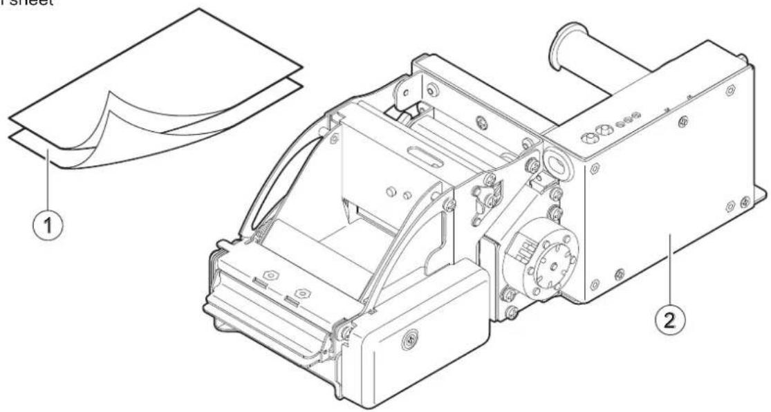
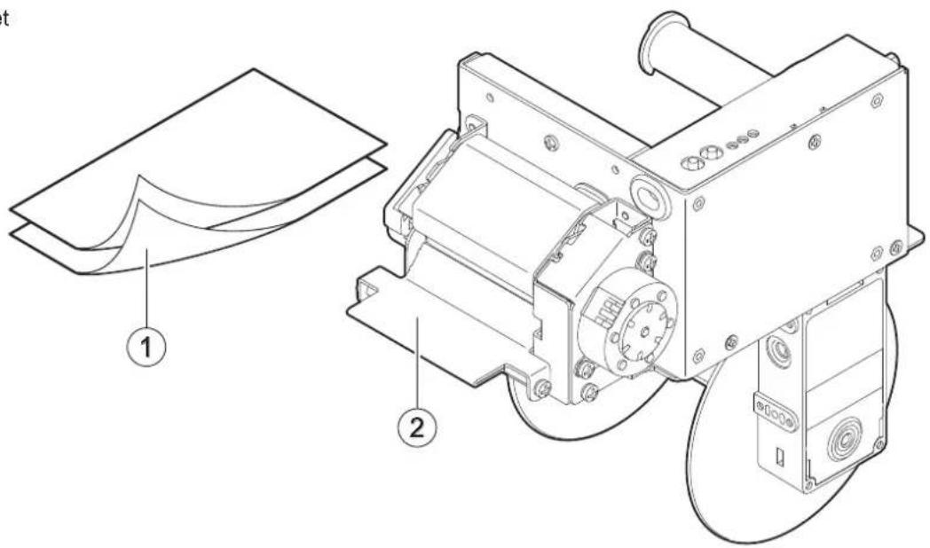
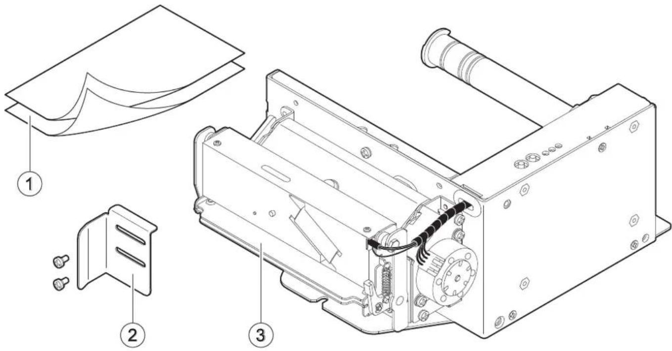
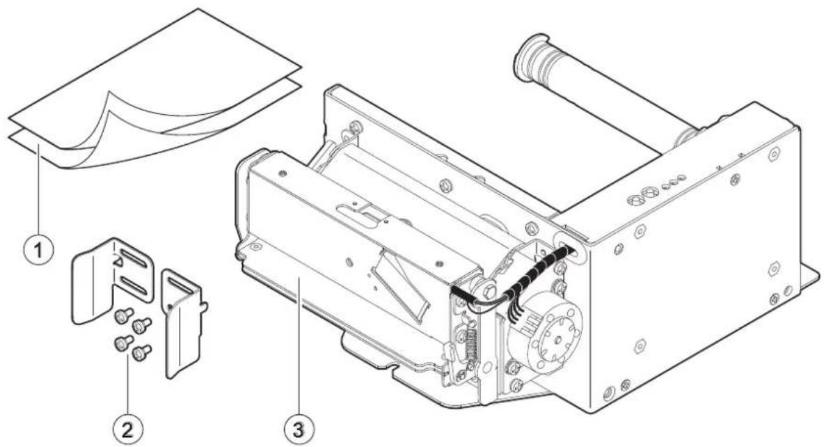
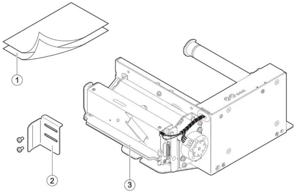
Make sure that all the components illustrated below are present and that there are no signs of damage. If there are, contact customer service.
TPTCM60III EJC
-
Installation instruction sheet
-
Device
TPTCM60IIIIL
-
Installation instruction sheet
-
Device
TPTCM112III, TPTCM112III 300 DPI
- Installation instruction sheet
- Paper guide bracket with fixing screws (x 2)
- Device
TPTCM112III STRONG CUT, TPTCM112III CL
- Installation instruction sheet
- Paper guide brackets (internal and external) with fixing screws (x 4)
- Device
TPTCM112III EJC, TPTCM112III EJC 300 DPI
- Installation instruction sheet
- Device
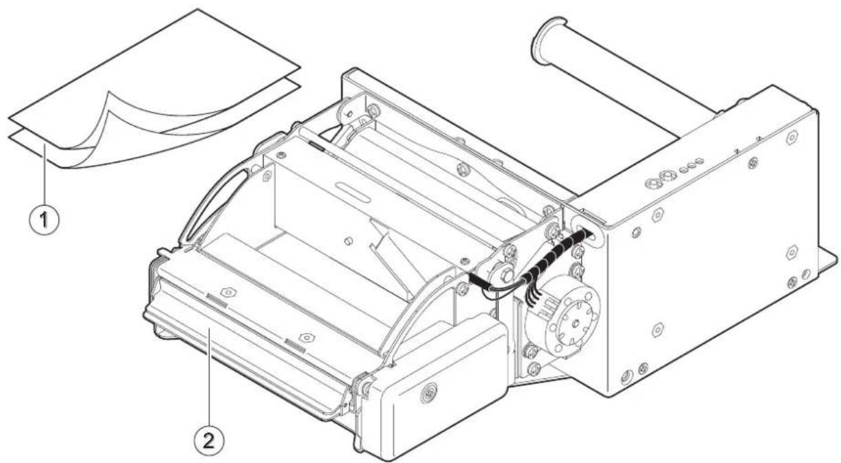
TPTCM112IIIL
- Installation instruction sheet
- Paper guide bracket with fixing screws (x 2)
- Device
3.2 Device components: external views
TPTCM60III EJC
- Printing mechanism + head temperature sensor
- Sensor for paper presence in input
- LF LINE FEED key
- FF FORM FEED key
- POWER ON led
- STATUS led
- Low paper led
- Paper input
- Internal ring for roll blocking
- RS232 serial port
- USB port
- Power supply port
-
Connector for low paper sensor + cap (for optional adjustable paper roll)
-
Low paper sensor
- Roll holder pin 60 mm
- External ring for roll blocking
- Cutter
- Inspection cover for ejector
- Sensor for paper presence in output
- Paper out
- Sensor for ejector position
- Cover for ejector gears
- Printing mechanism motor
- Device chassis
- Sensor for print head lifted
- Printing mechanism lifting lever
- Lifting lever for ejector
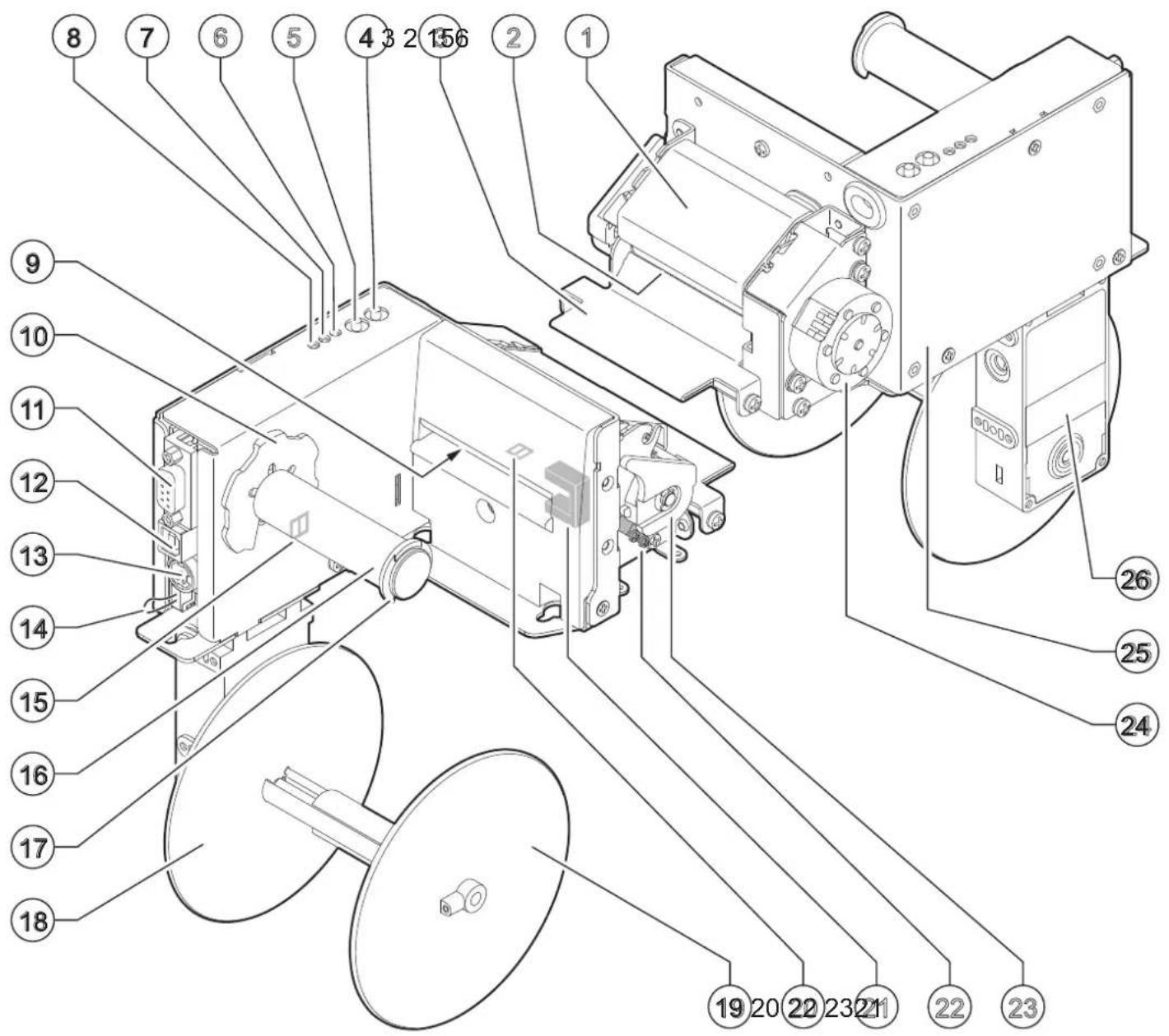
TPTCM60IIIIL
- Printing mechanism + head temperature sensor
- Paper out
- Peeler
- LF LINE FEED key
- FF FORM FEED key
- POWER ON LED
- STATUS LED
- Low paper LED
- Paper input
- Internal ring for roll blocking
- RS232 serial port
- USB port
-
Power supply port
-
Connector for low paper sensor + cap (for optional adjustable paper roll)
- Low paper sensor
- Roll holder pin 60 mm
- External ring for roll blocking
- Roll locking disc (fixed)
- Roll locking disc (adjustable)
- Sensor for paper presence in input
- Fork sensor for labels gap detection
- Sensor for print head lifted
- Printing mechanism lifting lever
- Printing mechanism motor
- Device chassis
- Rewinder motor
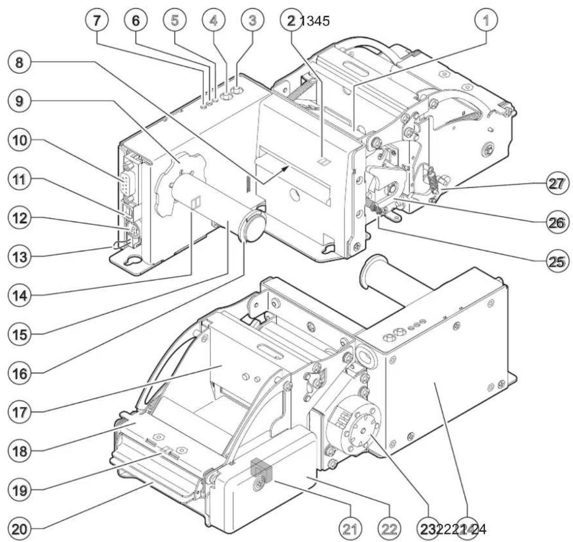
TPTCM112III, TPTCM112III 300 DPI, TPTCM112III CL
- Printing mechanism lifting lever
- Printing mechanism + head temperature sensor
- Sensor for black mark alignment
- LF LINE FEED key
- FF FORM FEED key
- POWER ON LED
- STATUS LED
- Low paper LED
- Paper input
- Internal ring for roll blocking
- RS232 serial port
- USB port
-
Power supply port
-
Connector for low paper sensor + cap (for optional adjustable paper roll)
- Low paper sensor
- Roll holder pin 80, 86, 100, 112 mm
- External ring for roll blocking
- Cutter
- Paper out
- Lifting lever for cutter
- Printing mechanism motor
- Device chassis
- Sensor for paper presence in input
- Sensor for print head lifted
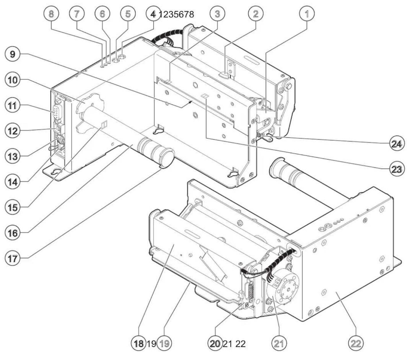
TPTCM112III STRONG CUT
- Printing mechanism lifting lever
- Printing mechanism + head temperature sensor
- Sensor for black mark alignment
- LF LINE FEED key
- FF FORM FEED key
- POWER ON LED
- STATUS LED
- Low paper LED
- Paper input
- Internal ring for roll blocking
- RS232 serial port
- USB port
-
Power supply port
-
Connector for low paper sensor + cap (for optional adjustable paper roll)
- Low paper sensor
- Roll holder pin 80, 86, 100, 112 mm
- External ring for roll blocking
- Strong Cut cutter
- Paper out
- Lifting lever for cutter
- Printing mechanism motor
- Device chassis
- Sensor for paper presence in input
- Sensor for print head lifted
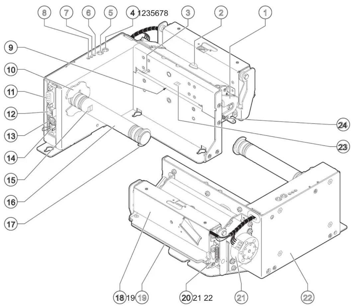
TPTCM112III EJC, TPTCM112III EJC 300 DPI
- Printing mechanism + head temperature sensor
- LF LINE FEED key
- FF FORM FEED key
- POWER ON LED
- STATUS LED
- Low paper LED
- Paper input
- Internal ring for roll blocking
- RS232 serial port
- USB port
- Power supply port
- Connector for low paper sensor + cap (for optional adjustable paper roll)
-
Low paper sensor
-
Roll holder pin 112 mm
- External ring for roll blocking
- Cutter
- Sensor for paper presence in output
- Paper out
- Inspection cover for ejector
- Sensor for ejector position
- Cover for ejector gears
- Printing mechanism motor
- Device chassis
- Sensor for paper presence in input
- Sensor for print head lifted
- Printing mechanism lifting lever
- Lifting lever for ejector
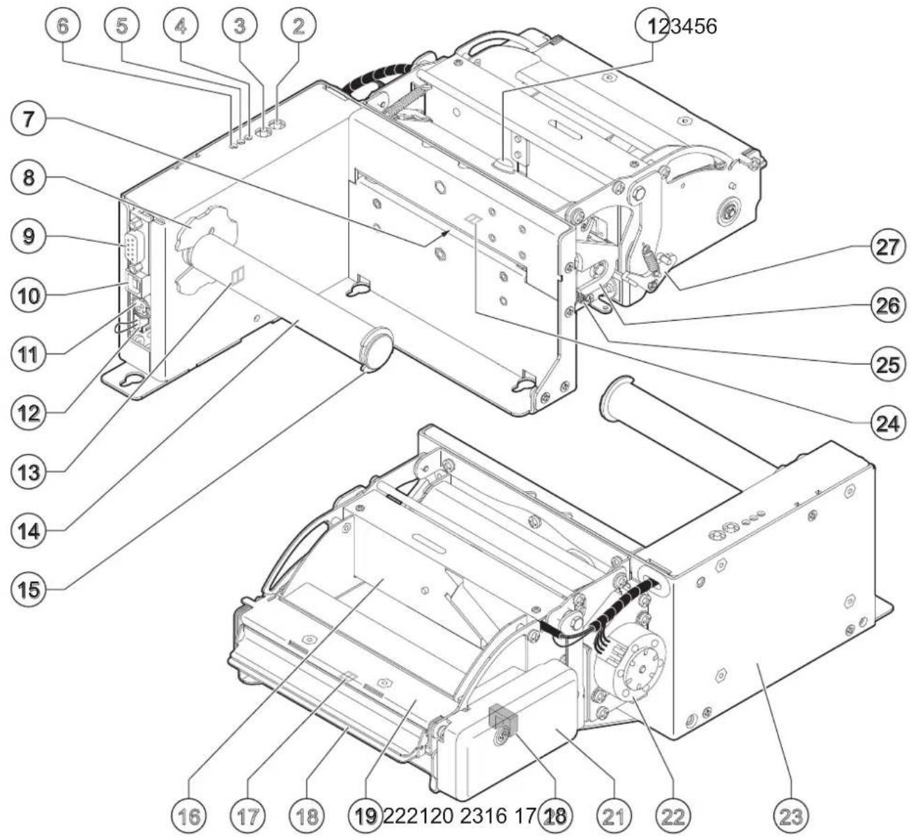
TPTCM112IIIL
- Printing mechanism lifting lever
- Printing mechanism + head temperature sensor
- Upper sensor for labels gap detection
- Lower sensor for labels gap detection
- LF LINE FEED key
- FF FORM FEED key
- POWER ON LED
- STATUS LED
- Low paper LED
- Paper input
- Internal ring for roll blocking
- RS232 serial port
-
USB port
-
Power supply port
- Connector for low paper sensor + cap (for optional adjustable paper roll)
- Low paper sensor
- Roll holder pin 101, 112 mm
- External ring for roll blocking
- Cutter
- Paper out
- Lifting lever for cutter
- Printing mechanism motor
- Device chassis
- Sensor for print head lifted
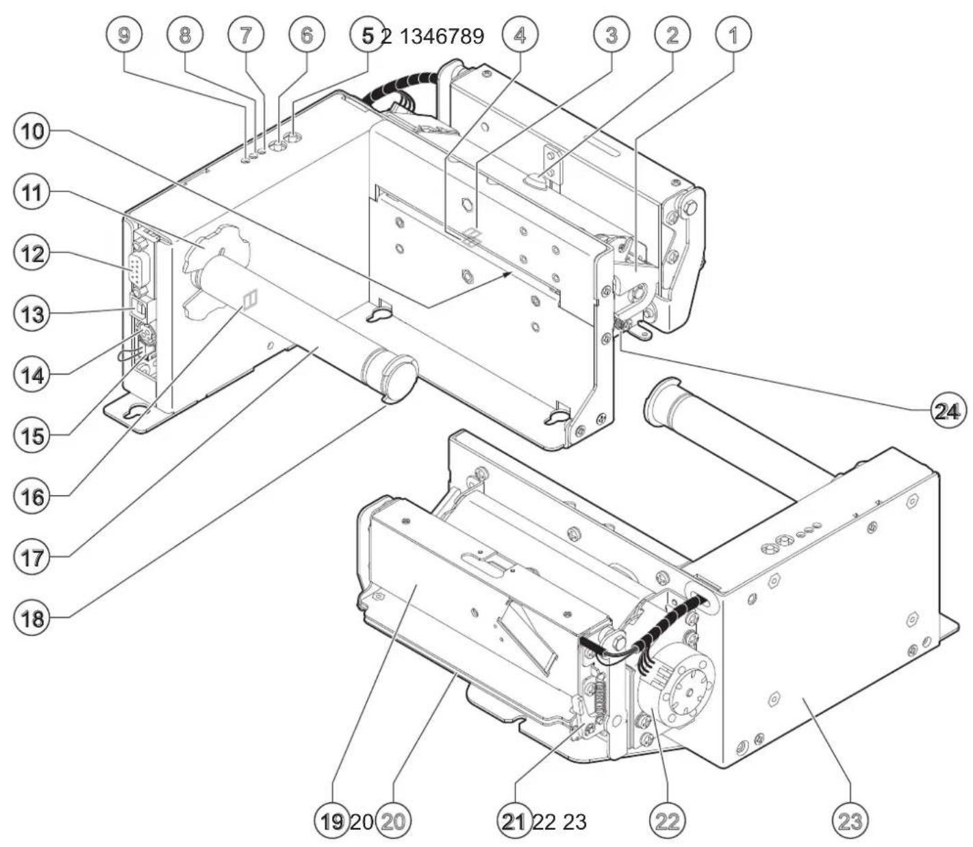
3.3 Product label
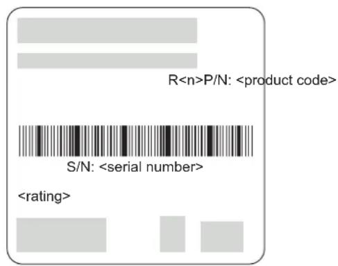
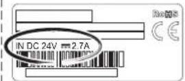
The main data used to identify the machine are shown on the label attached to the bottom of the device.
In particular, it shows the electrical data for the connection to a power source. It also shows the product code, the serial number and the hardware revision (R).
3.4 Key functions: power up
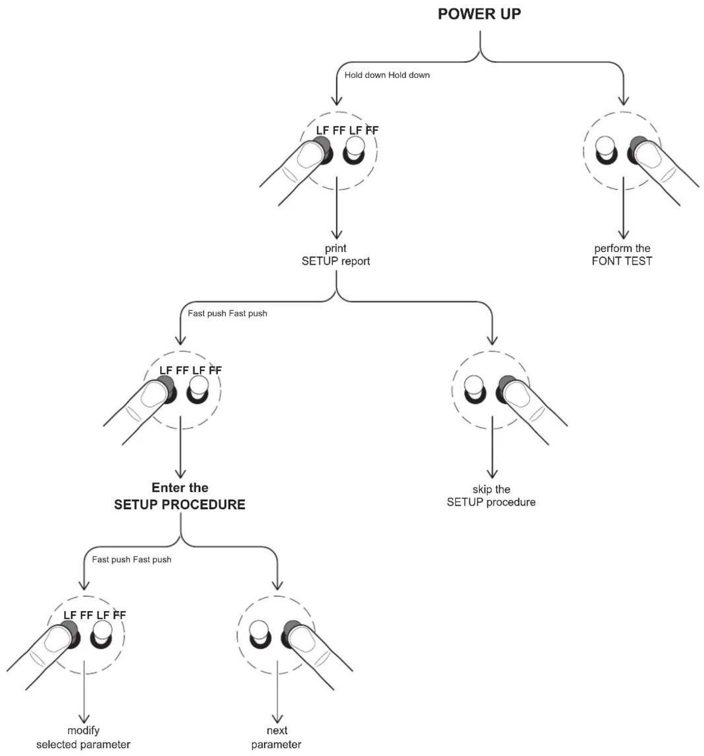
flowchart
graph TD
    A["POWER UP"] --> B["Hold down Hold down"]
    B --> C["LF FF LF FF"]
    C --> D["print SETUP report"]
    A --> E["perform the FONT TEST"]
    C --> F["Fast push Fast push"]
    F --> G["LF FF LF FF"]
    G --> H["Enter the SETUP PROCEDURE"]
    H --> I["Fast push Fast push"]
    I --> J["LF FF LF FF"]
    J --> K["modify selected parameter"]
    J --> L["next parameter"]
    G --> M["skip the SETUP procedure"]
3.5 Key functions: standby
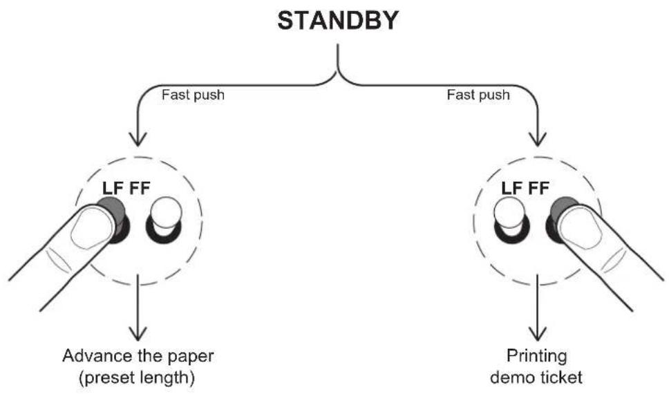
flowchart
graph TD
    A["STANDBY"] --> B["LF FF"]
    A --> C["LF FF"]
    B --> D["Advance the paper (preset length)"]
    C --> E["Printing demo ticket"]
    B --> F["Fast push"]
    C --> G["Fast push"]
3.6 Status messages
The three status LED indicate hardware status of device. Given in the table below are the various LEDs signals and the corresponding device status.
POWER ON LED
Signals the status of the powered device.
STATUS LED DESCRIPTION
- OFF DEVICE NOT POWERED
Signals the status of the powered device.
STATUS LED DESCRIPTION
Signals the hardware status of device.
| STATUS LED DESCRIPTION | |
| - OFF DEVICE OFF | |
| YELLOW | ON DEVICE ON: NO ERROR |
| x 2 PRINTHEAD OVERHEATED | |
| x 3 PAPER END | |
| x 4 POWER SUPPLY VOLTAGE INCORRECT | |
| x 5 RECEPTION ERROR(PARITY, FRAME ERROR, OVERRUN ERROR) | |
| x 6 COMMAND NOT RECOGNIZED | |
| x 7 COMMAND RECEPTION TIME OUT | |
| x 8 PRINTHEAD LIFTED | |
| x 9 PAPER JAM | |
| x 10 AUTOCUTTER ERROR | |
| x 11 RAM ERROR | |
| x 12 EXTERNAL MEMORY ERROR | |
4 INSTALLATION
4.1 Fastening
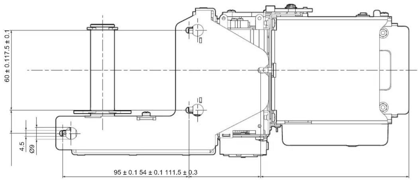
All the dimensions shown in following figures are in millimetres.
ATTENTION: Correctly prepare the fixing holes for screws and the drilling for the paper mouth in order to avoid deformation and torsion of the device or its components which could compromise its operation.
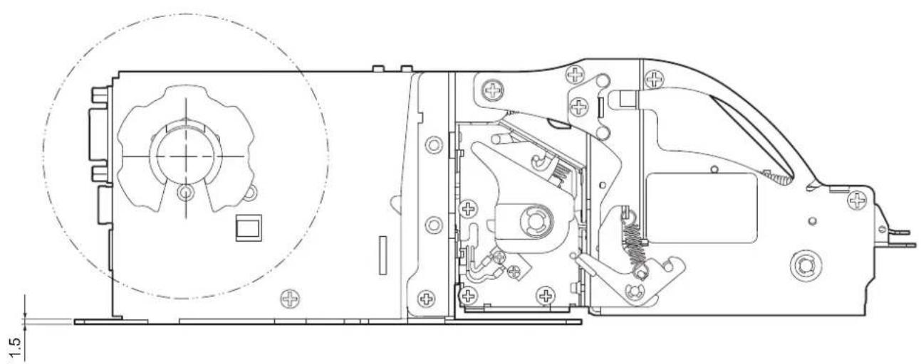
TPTCM60III EJC
The device is provided with three fixing holes on the bottom of device (see following figure). To install the device on a panel, use three M4 screws.
natural_image
Technical line drawing of a mechanical assembly with internal components and a circular detail (no text or symbols)TPTCM60IIIIL
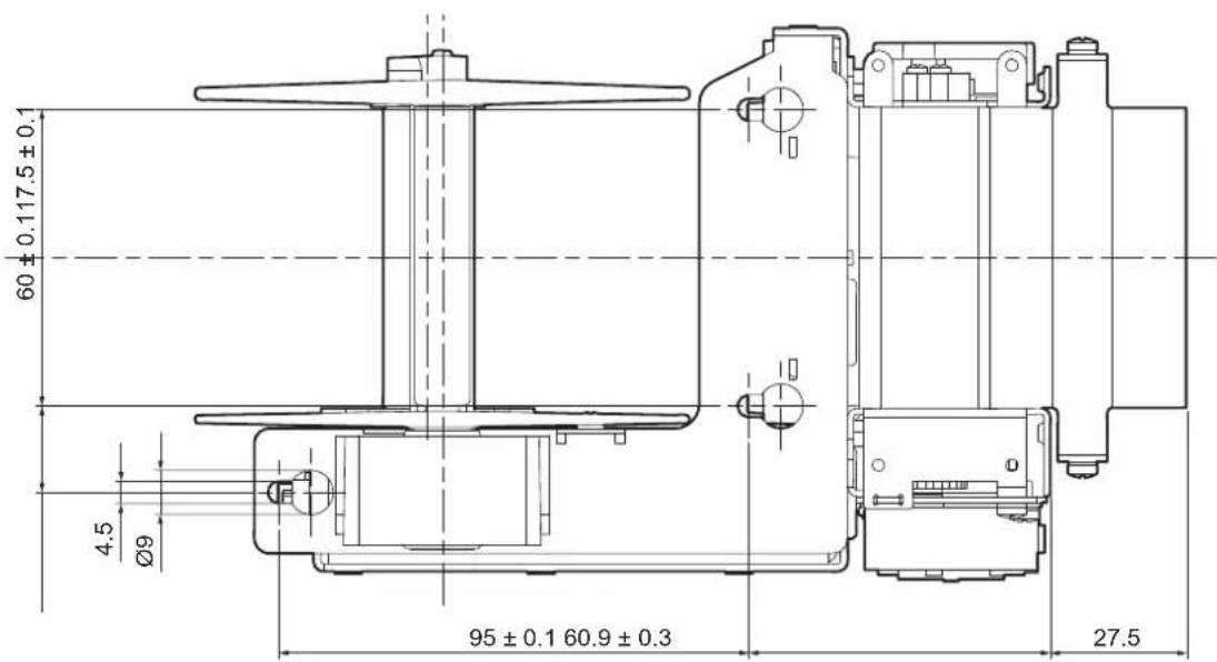
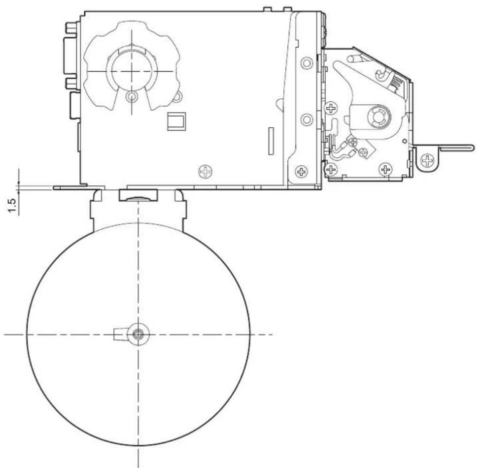
The device is provided with three fixing holes on the bottom of device (see following figure).
To install the device on a panel, use three M4 screws.
Prepare the panel considering the presence of the rewinder and the paper path (see paragraph 5.4 and paragraph 9.3).
natural_image
Technical line drawing of a mechanical device with circular base and gear mechanism (no text or symbols)TPTCM112III, TPTCM112III EJC, TPTCM112III STRONG CUT, TPTCM112IIIIL, TPTCM112III CL
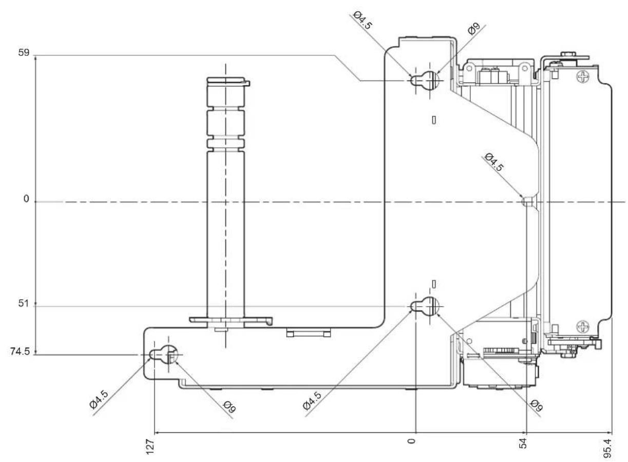
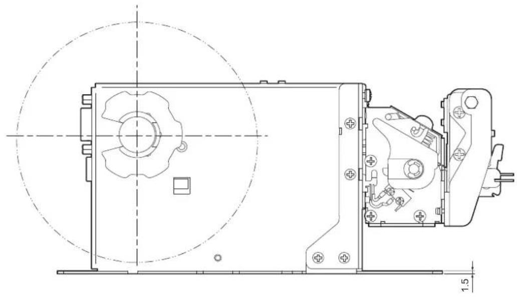
The device is provided with four fixing holes on the bottom of device (see following figure).
To install the device on a panel, use four M4 screws.
natural_image
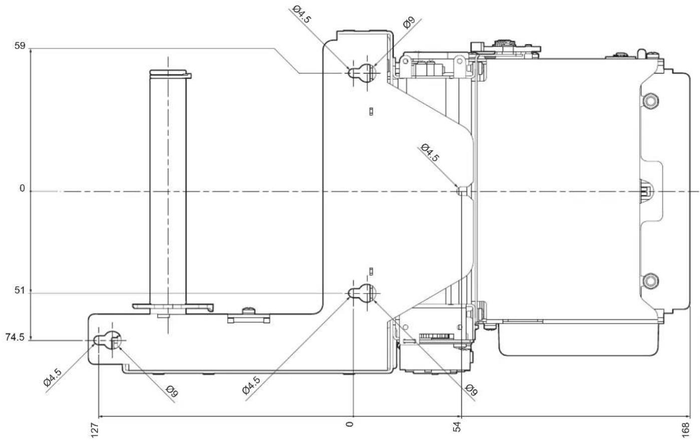
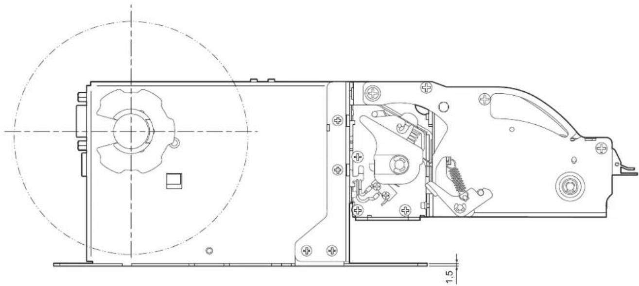
Technical line drawing of a mechanical assembly with circular and linear features, no visible text or symbolsThe device is provided with four fixing holes on the bottom of device (see following figure).
To install the device on a panel, use four M4 screws.
natural_image
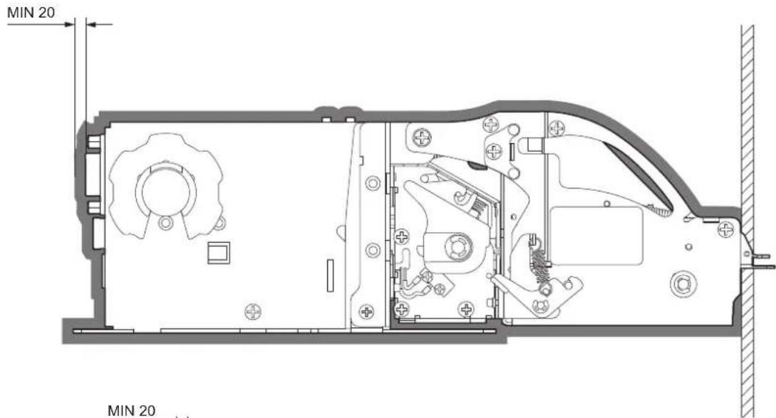
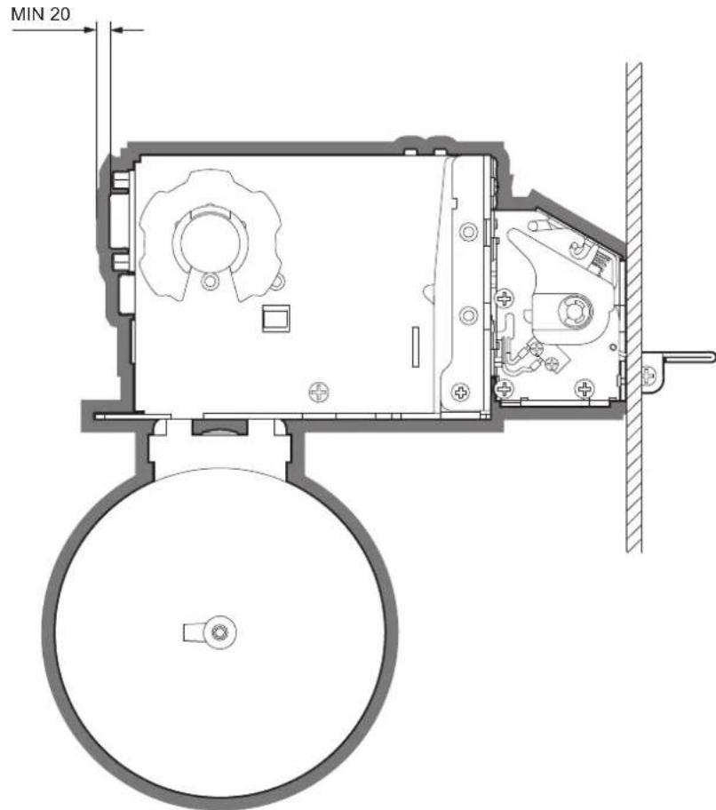
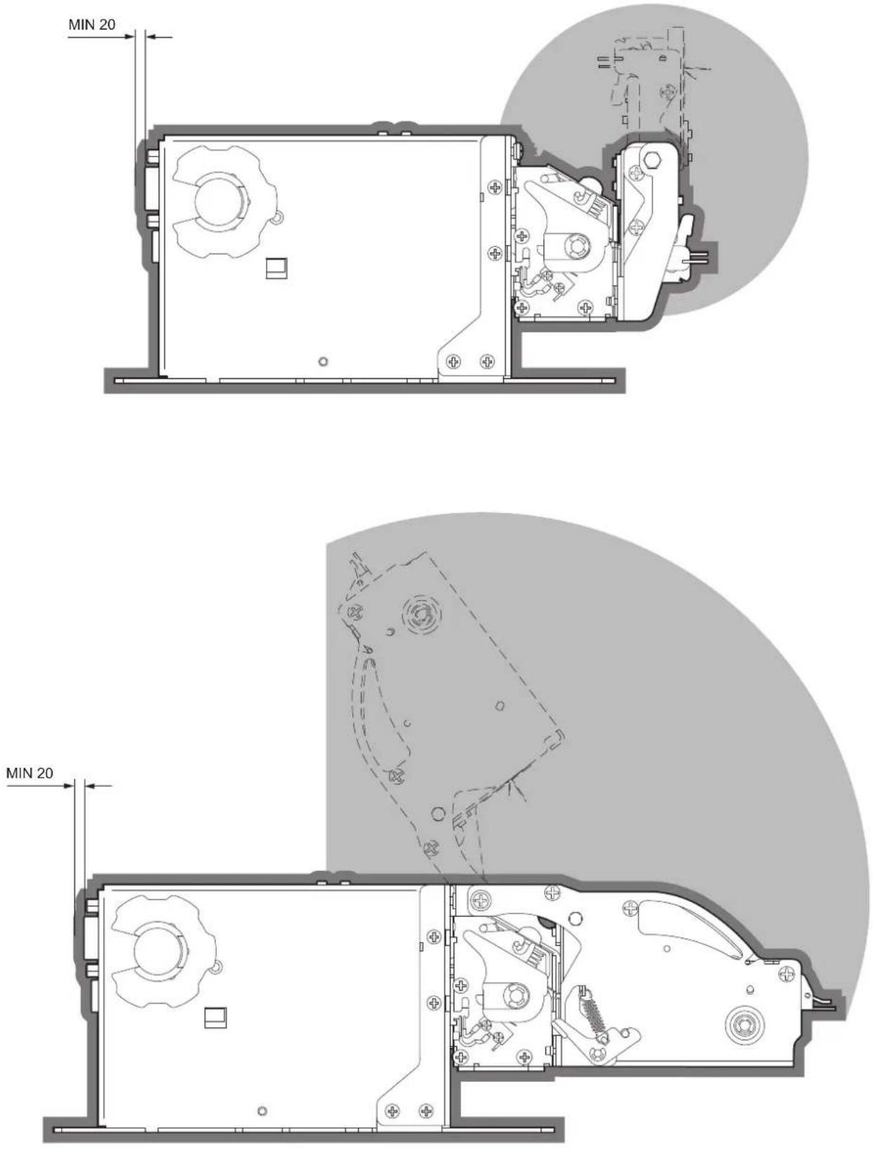
Technical line drawing of a mechanical device with internal components and mounting holes (no text or symbols)When you place the device in the operating position, make sure to leave the proper free space around the device of at least 20mm , also considering the space for activating the mobile components so to not compromise operation and maintenance.
Refer to paragraph 9.3 for models dimensions.
4.2 Connections
The following figure shows the possible connections for the device. When the RS232 and USB communication cables are connected to the device at the same time, communication takes place via the USB port.
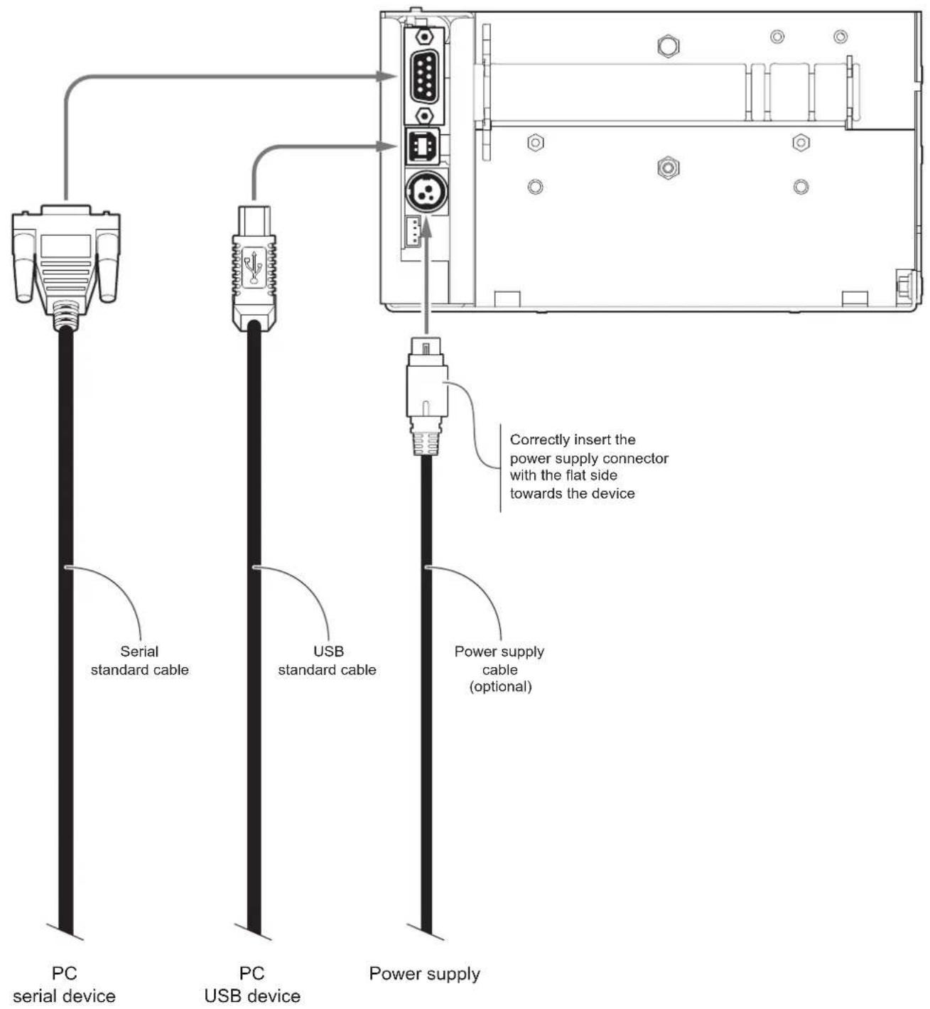
ATTENTION: In some conditions, we recommend the installation of a ferrite core on the power supply cable.
4.3 Pinout
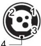
POWER SUPPLY
Tripolar female connector

The following figure shows the connector pinout of power supply cable:
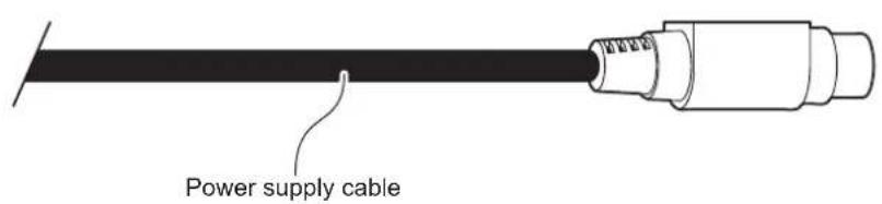
Tripolar male connector
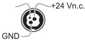
ATTENTION:
Respect power supply polarity.
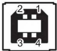
USB INTERFACE
Female USB type B connector

flowchart
graph LR
    A["J12"] --> B["1 JSB0_VBUS (out)"]
    A --> C["2 JSB0_D-"]
    A --> D["3 JSB0_D+"]
    A --> E["4 GND"]
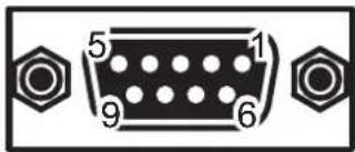
RS232 SERIAL INTERFACE
Female DB9 connector
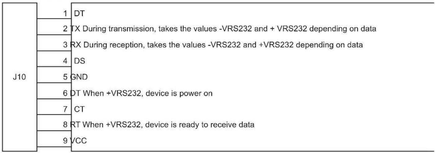
Given the presence of the RS232 standard, logic value "0" corresponds to the voltage value +VRS232 (voltage value between +3Vdc and +15Vdc) and logic value "1" corresponds to the voltage value -VRS232 (voltage value between -3Vdc and -15Vdc.
DEVICE > PC connection
The following picture shows an example of connection between the device and a personal computer using a 9 pin RS232 serial connector:
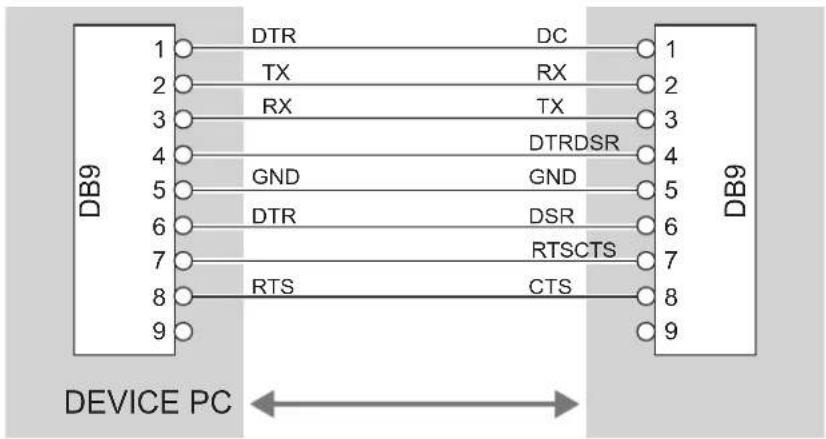
When use a serial cable, we recommend the installation of a ferrite core on the power supply cable.
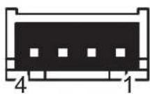
LOW PAPER
4 ways male JST connector (S4B-PH-K-S)

The following figure shows the pinout of the connector of the cable for low paper to use for the device:
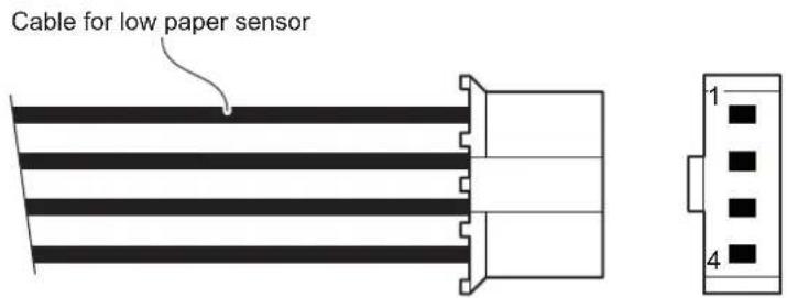
Female JST connector series PHR-4
| PIN | color | SignalCab |
| 1 | Red | +5V |
| 2 | Blue | NPE (input) |
| 3 | Black | n.c. |
| 4 | Yellow | GND |
4.4 Driver and SDK
The drivers for the following operating system are available in the website www.custom4u.it:
| OPERATING SYSTEM DESCRIPTION INSTALLATION PROCEDURE | ||
| Windows | Driver for Windows XP | From the START menu, press Run and type-in the path where the SW was saved on your PC, then click OK. Follow the instructions that appear on the screen to install the driver. |
| Driver for Windows VISTA (32/64 bit) | ||
| Driver for Windows 7 (32/64 bit) | ||
| Driver for Windows 8 (32/64 bit) | ||
| Driver for Windows 8.1 (32/64 bit) | ||
| Driver for Windows 10 (32/64 bit) | ||
| Self-installing driver for Virtual COM (32/64 bit)(see paragraph 6.5) | ||
| Linux 32/64 bit | Follow the instruction get back on the “Readme.txt” file. You can find it in the software package downloaded in advance. | |
5 OPERATION
5.1 Adjusting paper width
The devices manage only 60 mm paper width roll. However, it is necessary to correctly place the two rings for roll blocking (internal and external) to ensure the right paper alignment inside the device.
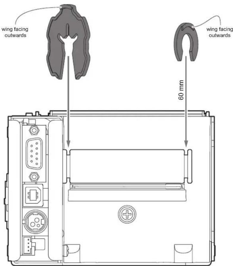
TPTCM112III, TPTCM112III 300 DPI, TPTCM112III EJC, TPTCM112III EJC 300 DPI, TPTCM112III
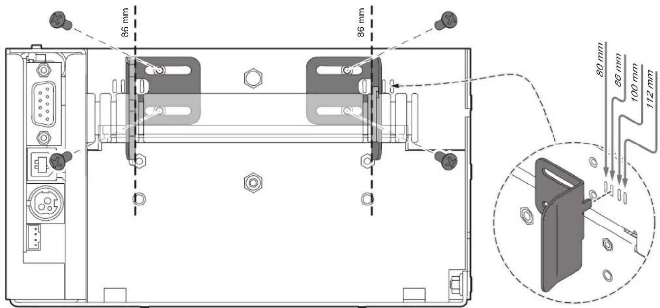
Paper width may be set to 80, 100 or 112 mm by assembling the internal adjustment ring and modifying the position of the external adjustment rings to ensure the right paper alignment inside the device (see the following figure).
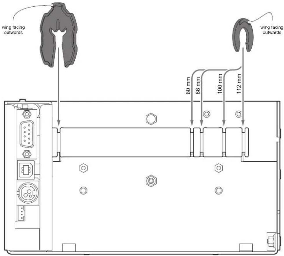
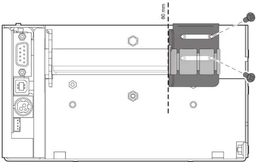
To manage paper width of 80, 86 or 100 mm, fix and correctly place the paper guide bracket provided with the device. The following figure shows an example of bracket fixing for 80 mm paper width.
TPTCM112III STRONG CUT, TPTCM112III CL
Paper width may be set to 80, 86, 100 or 112 mm by modifying the position of the adjustment rings (internal and external) to ensure the right paper alignment inside the device (see the following figure).
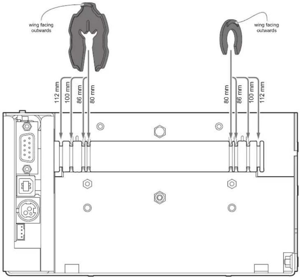
To manage paper width of 80, 86 or 100 mm, fix and correctly place the two paper guide brackets provided with the device. The following figure shows an example of bracket fixing for 86 mm paper width.
5.2 Switch the device on
1
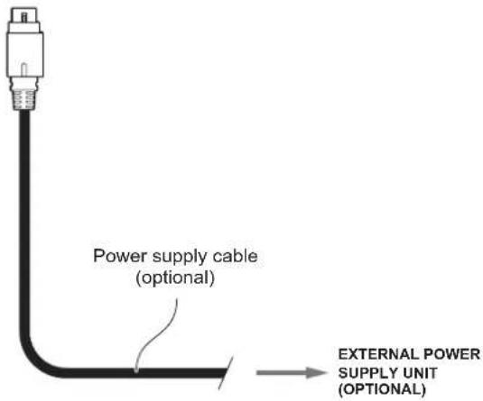
Connect the power supply cable to an external power supply unit.
2
TPTCM60III EJC
TPTCM60IIIIL
TPTCM112III,
TPTCM112III STRONG CUT,
TPTCM112III EJC
TPTCM112III
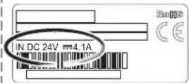
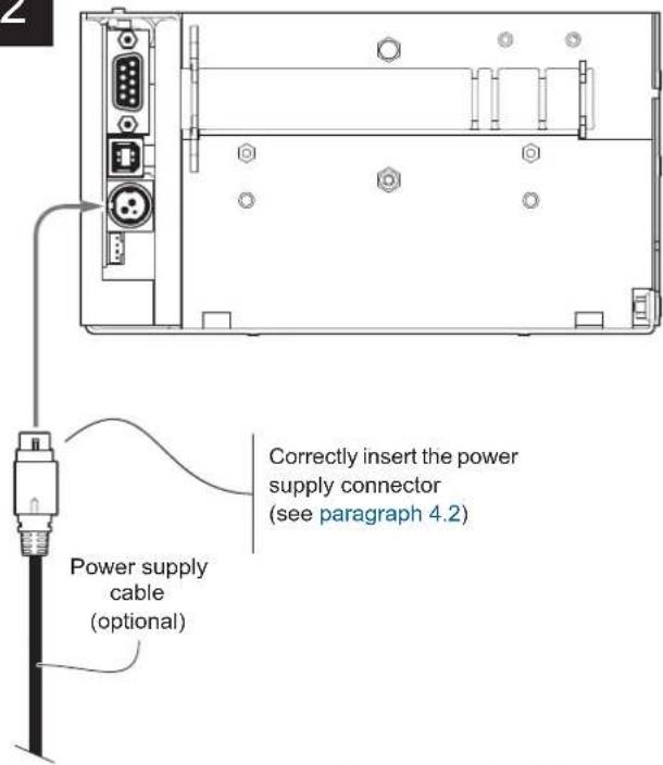
Connect the power supply cable to the device.
Use the type of electrical power supply
indicated on the label.
3
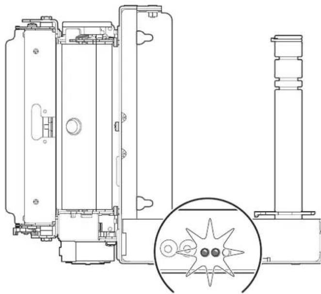
natural_image
Technical line drawing of a mechanical assembly with a magnified inset showing internal components (no text or symbols)The status LED (yellow) and the power on LED (green) turn on and the device is ready.
5.3 Loading the paper roll
To load the paper proceed as follows.
At every change of paper, check inside the device to locate and remove any scraps of paper.
natural_image
Technical line drawing of a computer case with labeled components and an external component (no text or symbols present)Assemble the two rings (see paragraph 5.1)
2
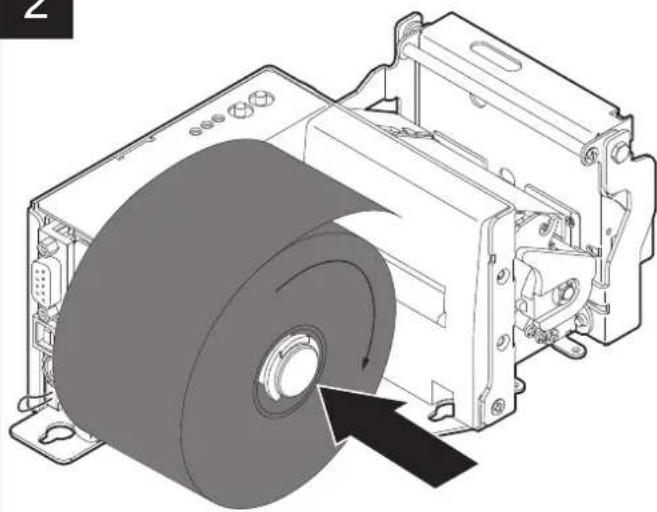
natural_image
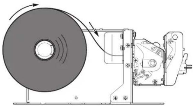
Technical illustration of a mechanical assembly with a rotating disk and housing (no text or symbols)Insert the paper roll on the pin so that it unrolls correctly.
3

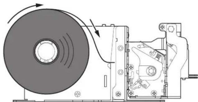
natural_image
Technical line drawing of a mechanical assembly with rotating disk and housing (no text or symbols)Insert the paper into the input mouth.
4
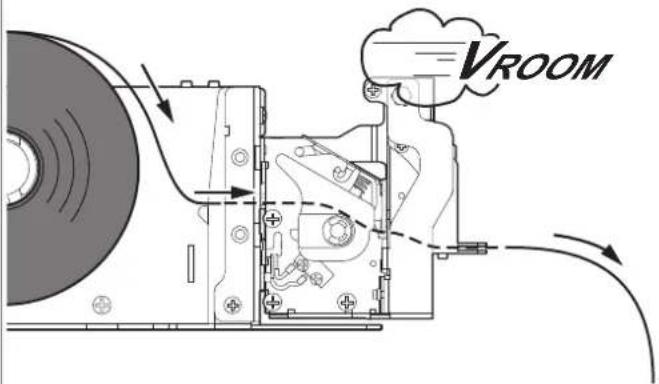
Wait until the paper is automatically loaded and cut.
TPTCM112III, TPTCM112III 300 DPI, TPTCM112III STRONG CUT, TPTCM112III EJC, TPTCM112III EJC 300 DPI, TPTCM112IIIIL, TPTCM112III CL
1
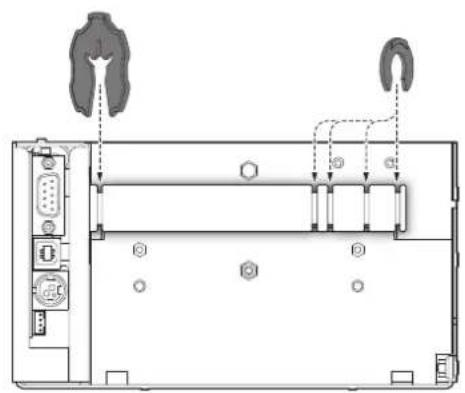
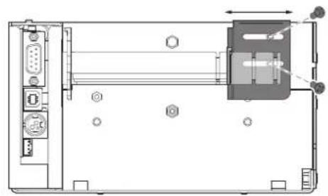
natural_image
Technical line drawing of a mechanical assembly with ports, connectors, and a central component (no text or symbols)If necessary, adjust the paper width by assembling the two rings and the paper guides (see paragraph 5.1).
2
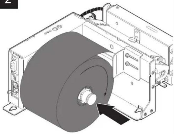
natural_image
Technical illustration of an electric motor assembly with a rotating wheel and mounting bracket (no text or symbols)Insert the paper roll on the pin so that it unrolls correctly.
3

natural_image
Mechanical assembly diagram showing a rotating disc and motor mechanism (no text or symbols)Insert the paper into the input mouth. Be sure that the paper is correctly positioned into paper guides.
4
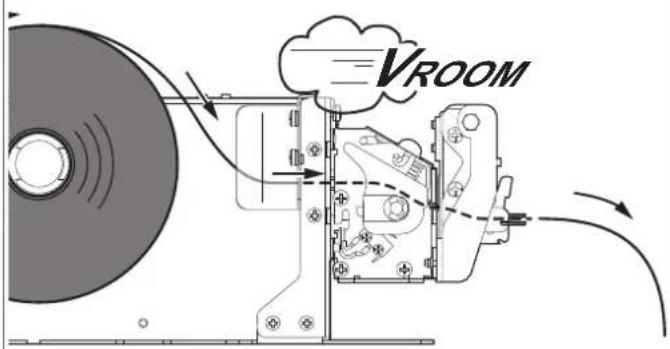
Wait until the paper is automatically loaded and cut.
5.4 Fixing the paper on rewinder
TPTCM60III
1
natural_image
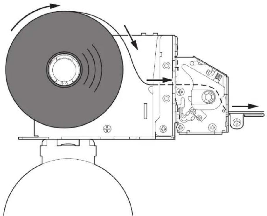
Technical line drawing of a mechanical device with rotating components and directional arrows indicating motion (no text or symbols)Insert the paper into the device (see paragraph 5.3).
2
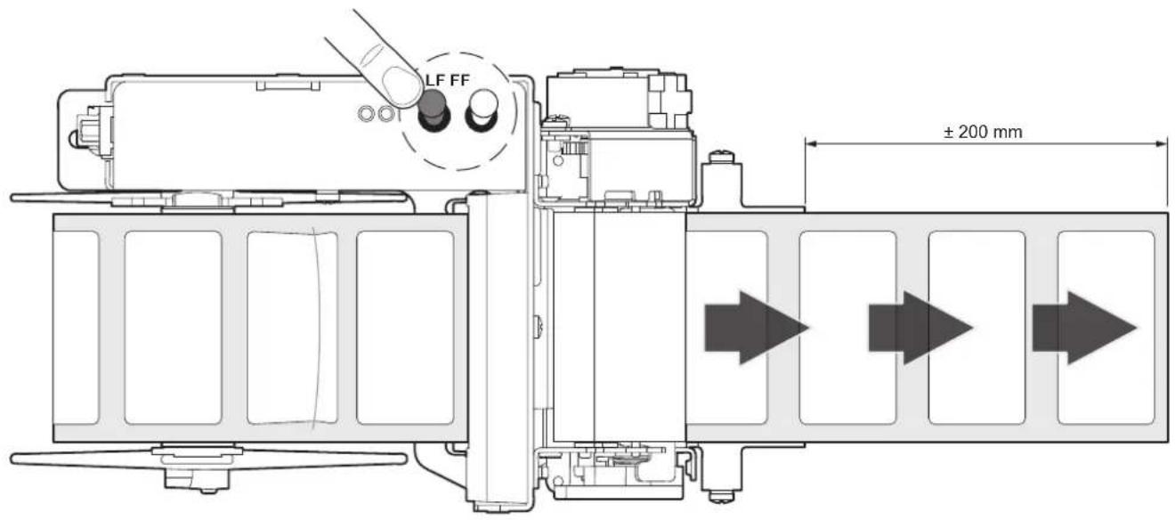
Press the LF LINE FEED button repeatedly to advance the paper of at least 200 mm beyond the edge of the peeler.
3
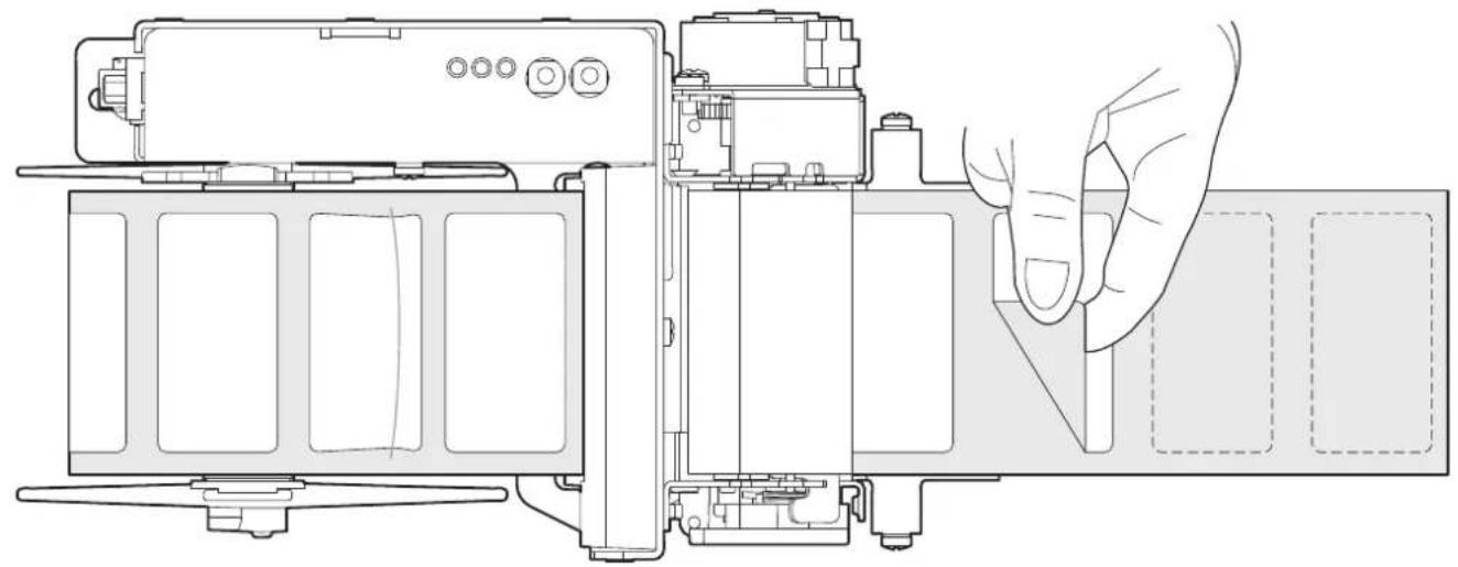
natural_image
Technical line drawing of a device interior showing internal components and a hand interacting with a screen (no text or symbols present)Remove all labels on the media, beyond the paper mouth.
4
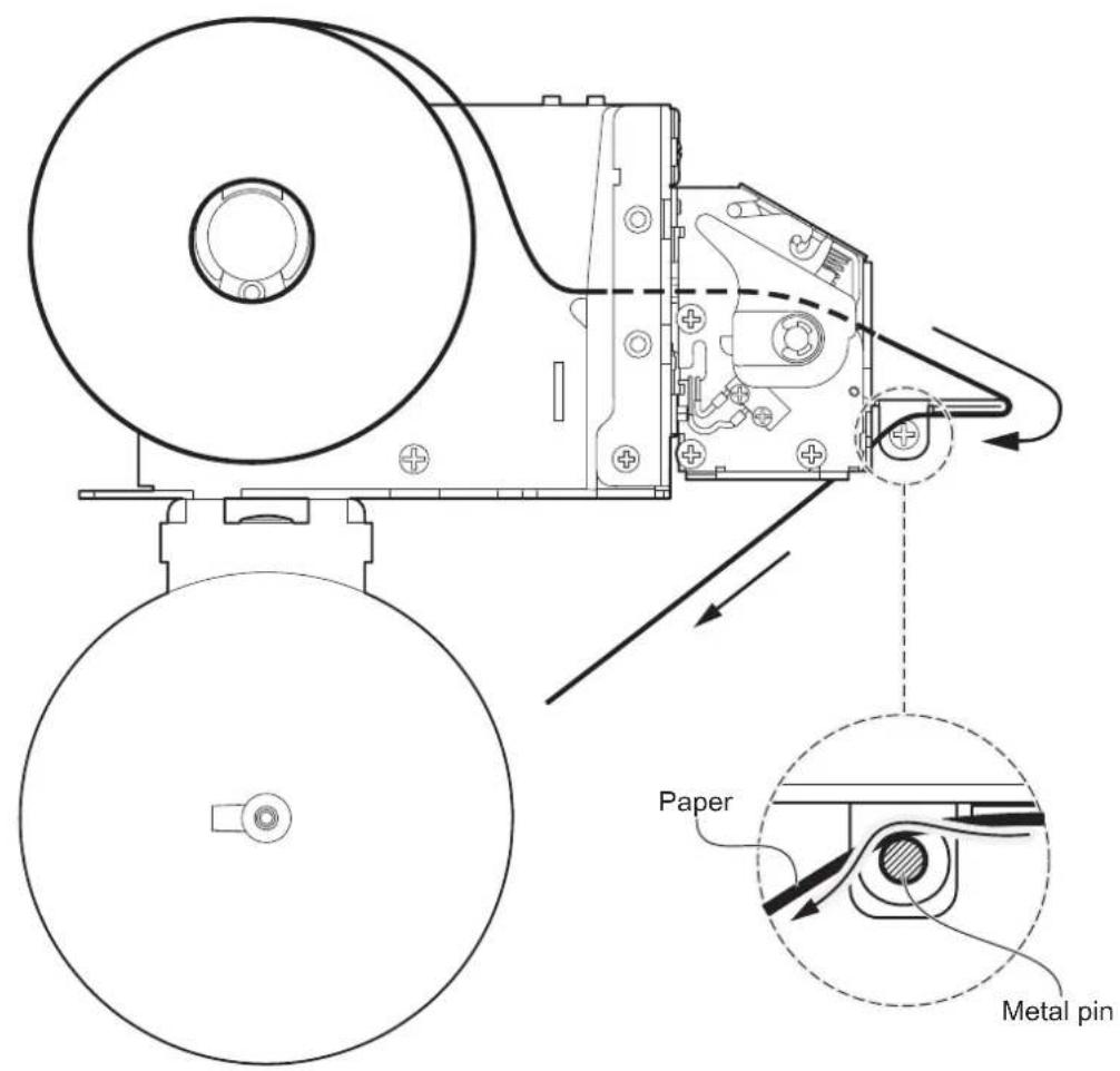
Pull the paper toward the rewinder respecting the path indicated by the arrows.
5
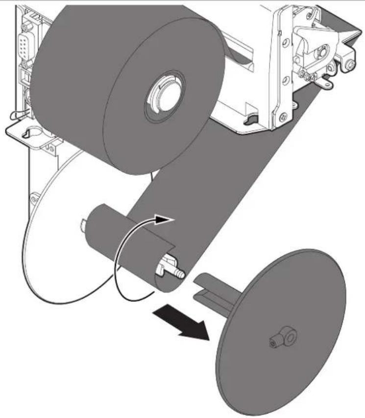
natural_image
Mechanical assembly diagram showing a roller being loaded onto a housing with a belt drive (no text or symbols present)Remove the rewinder plastic disk and wrap the paper around the pin as indicated by the arrow.
6
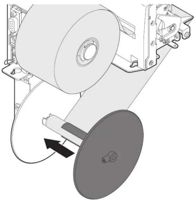
natural_image
Mechanical assembly diagram showing a roller being inserted into a housing with a rotating component (no text or symbols)Block the paper by inserting the plastic disk.
5.5 Issuing ticket
The device allows you to choose between different operating modes for the issuance of printed tickets.
The operating modes shown in the following images, depend on the settings of the configuration parameters and commands sent to the device.
"PRINT" mode - TPTCM112III, TPTCM112III 300 DPI, TPTCM112III STRONG CUT, TPTCM112IIIIL, TPTCM112III CL
1
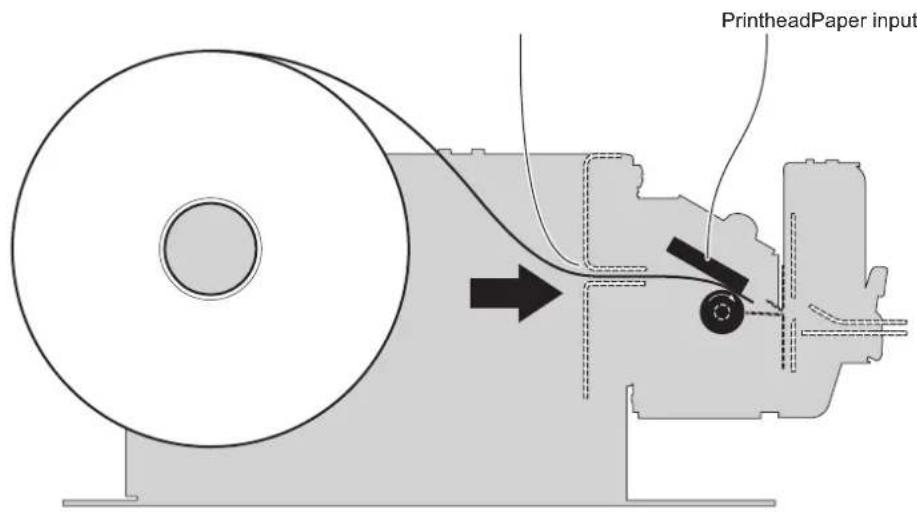
The device starts the ticket printing.
2
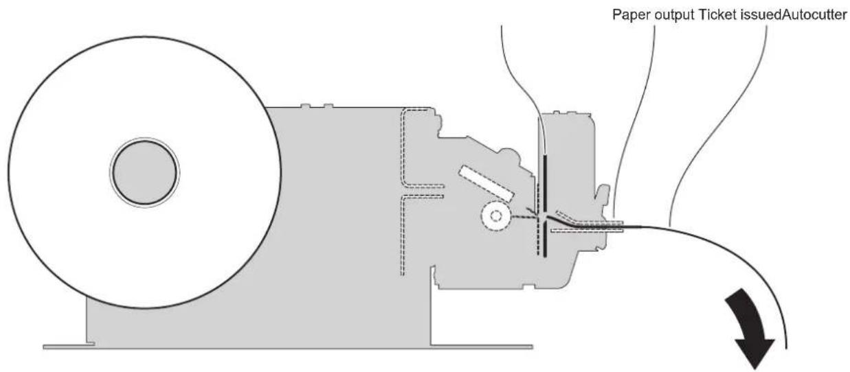
When printing ends, the device cuts the ticket printed that is issued from the paper output.
NOTE: To enable this operating mode, you need to send a cut command when the printing ends (see commands manual).
1
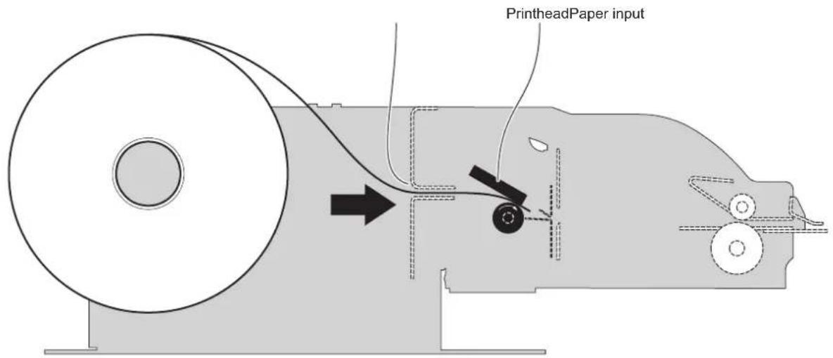
The device starts the ticket printing.
2
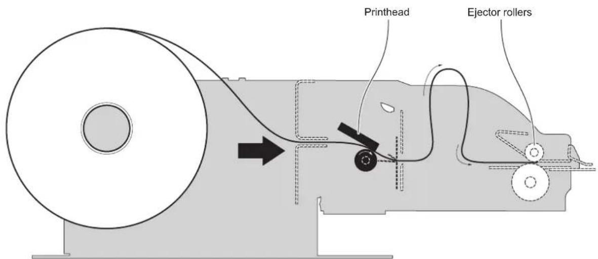
The ticket advances ahead to the ejector and is caught between the ejector rollers. The printed part of ticket is collected into the ejector group while the device continues printing.
3
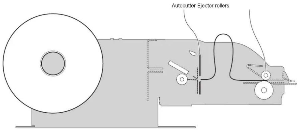
When printing ends, the device cuts the ticket printed
4
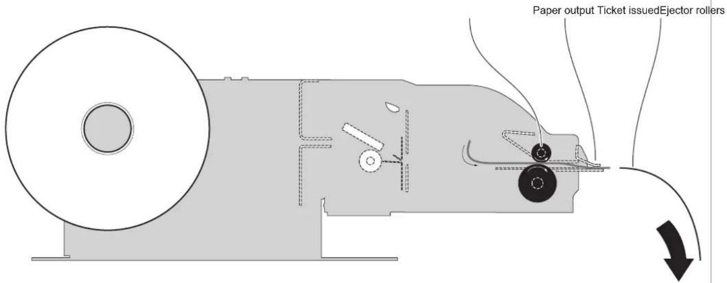
The device directly ejects the ticket
NOTE: To enable this issuing mode, you need to correctly set the operation mode of the ejector with the command 0x1D 0x65 (see commands manual).
1
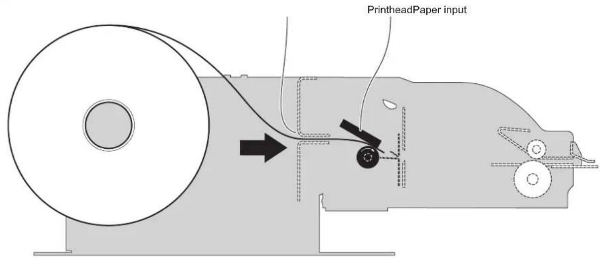
The device starts the ticket printing.
2
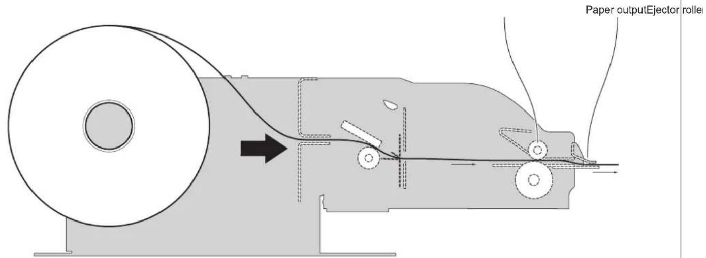
The ticket goes beyond the ejector rollers and starts to come out of the paper output.
3
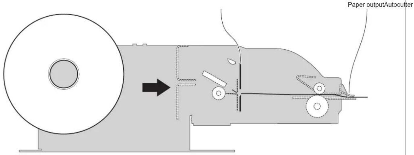
When printing ends, the device cuts the ticket printed.
4
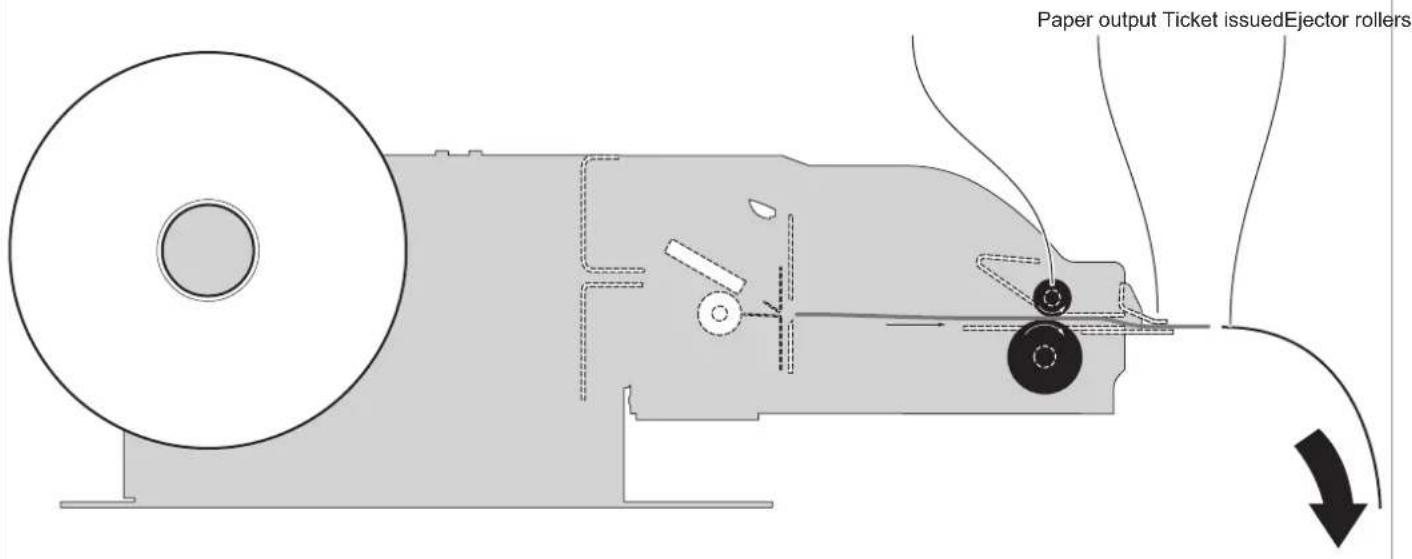
The device ejects the ticket.
NOTE: To enable this issuing mode, you need to correctly set the operation mode of the ejector with the command 0x1D 0x65 (see commands manual).
1
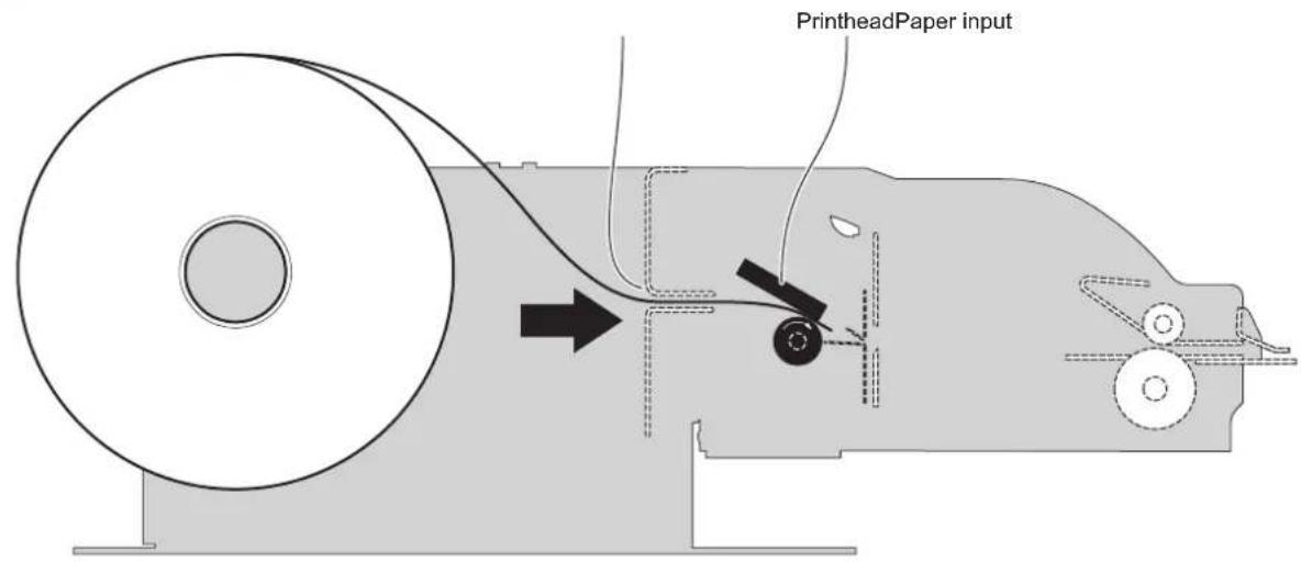
The device starts the ticket printing.
2
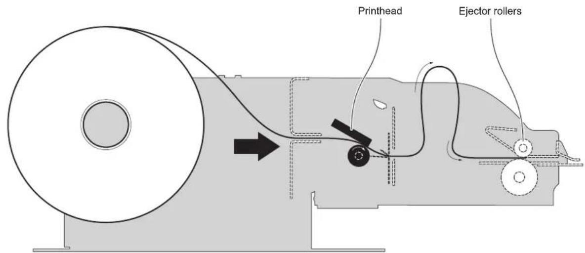
The ticket advances ahead to the ejector and is caught between the ejector rollers. The printed part of ticket is collected into the ejector group while the device continues printing.
3
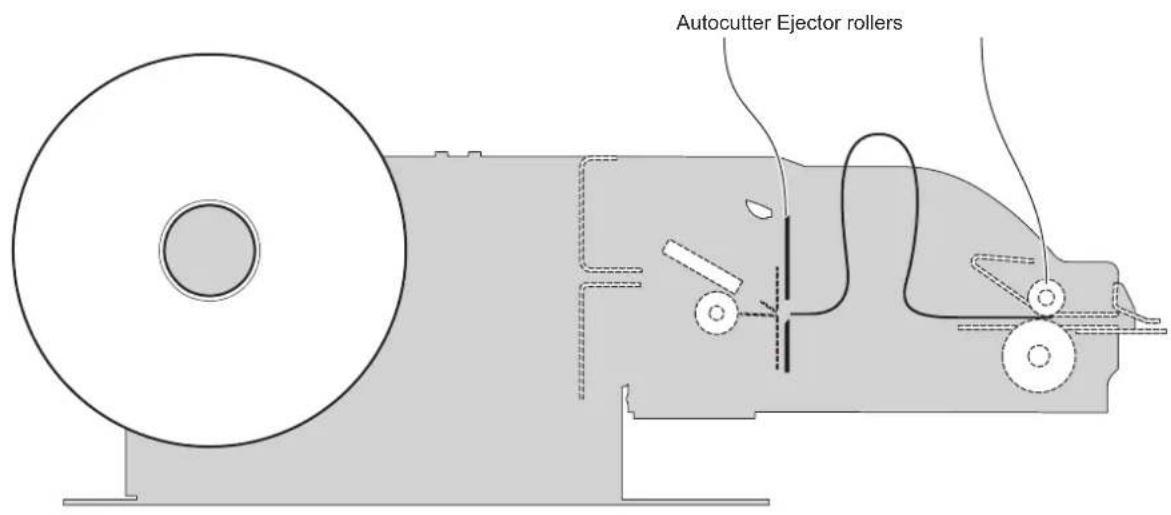
When printing ends, the device cuts the ticket printed.
4
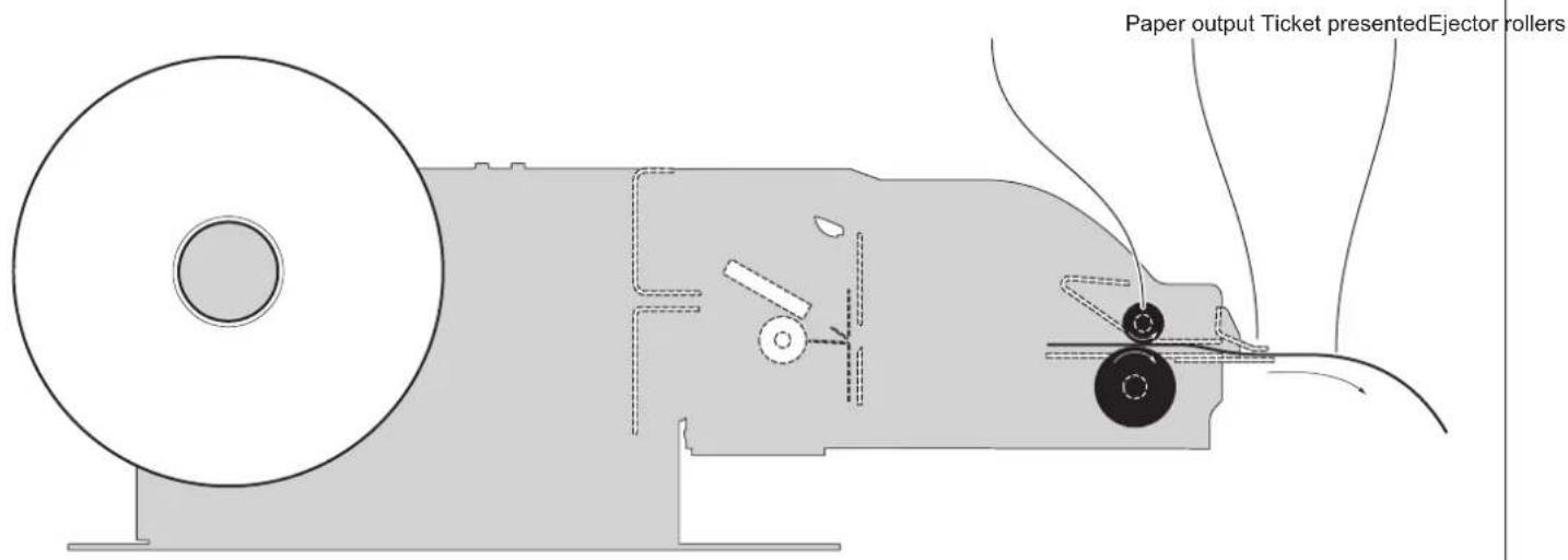
The device presents the ticket printed on the paper output.
5
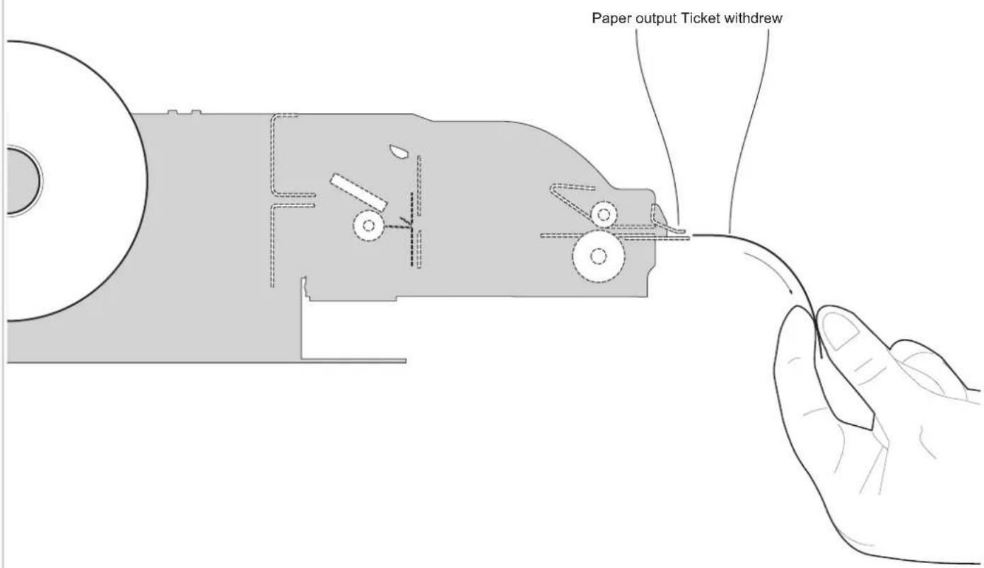
The user withdraws the ticket from the paper output.
NOTE: To enable this issuing mode, you need to correctly set the operation mode of the ejector with the command 0x1D 0x65 (see commands manual) and the setup parameter "Automatic Ejecting" (see chapter 6).
1
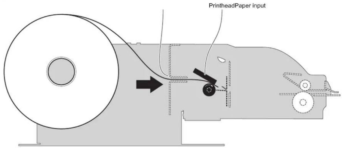
The device starts the ticket printing.
2
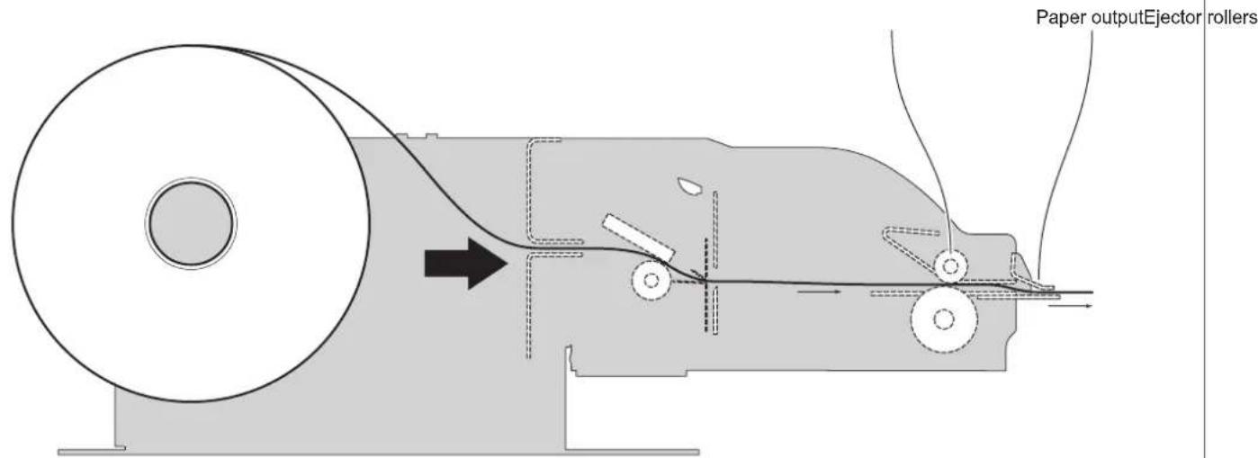
The ticket goes beyond the ejector rollers and stanrts to come out of the paper output
3
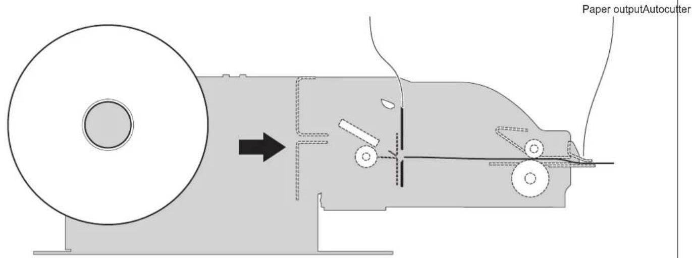
When printing ends, the device cuts the ticket printed.
4
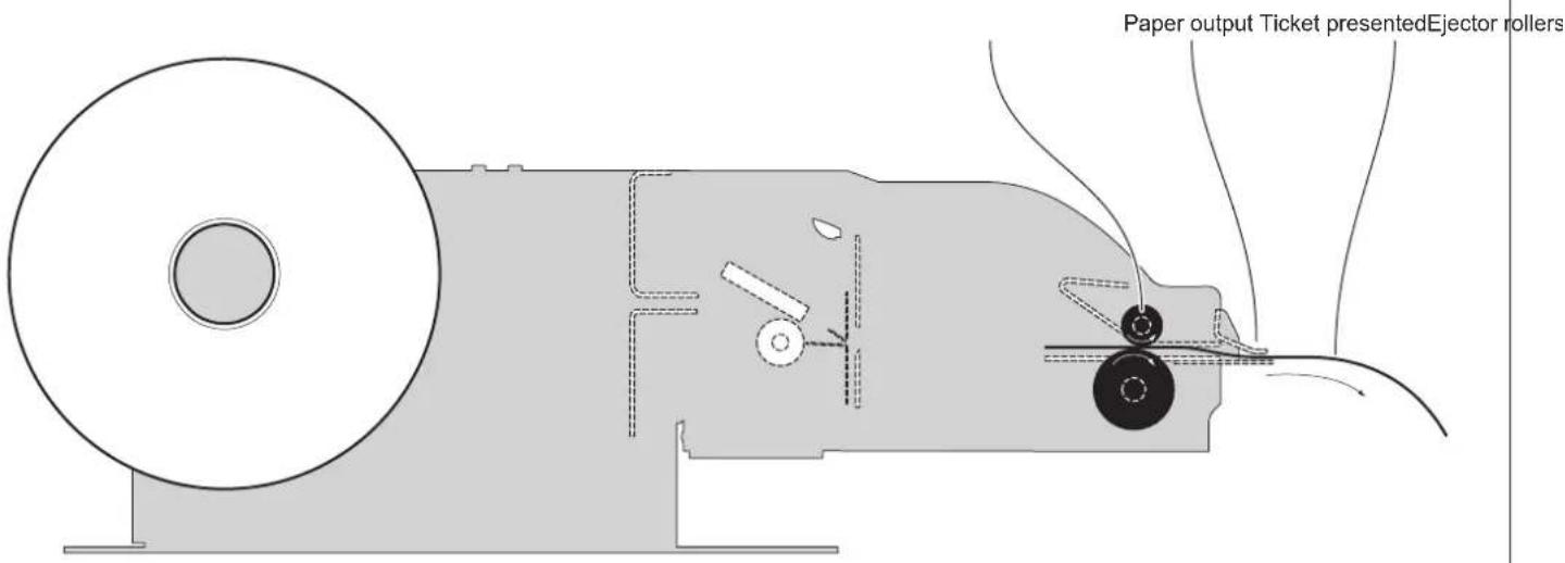
The device presents the ticket printed on the paper output.
5
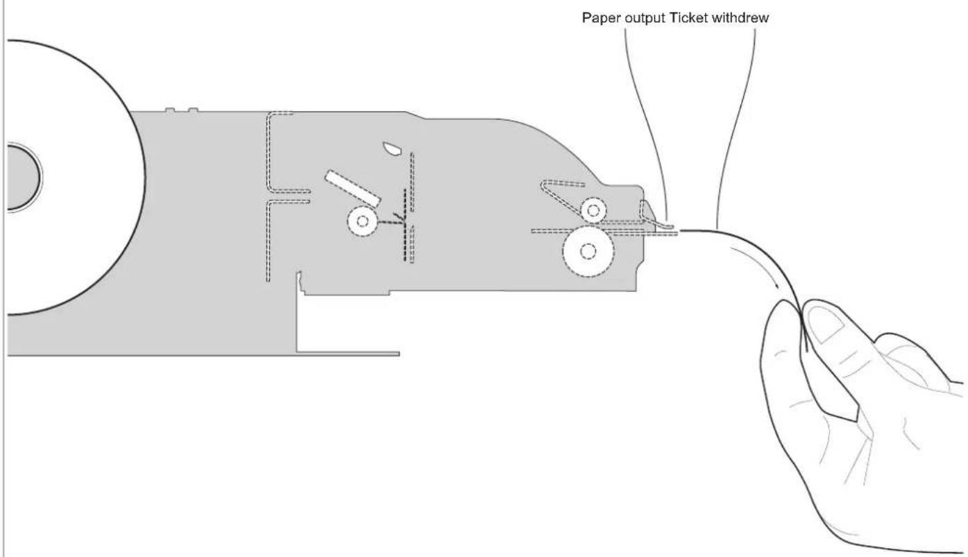
The user withdraws the ticket from the paper output.
NOTE: To enable this issuing mode, you need to correctly set the operation mode of the ejector with the command 0x1D 0x65 (see commands manual) and the setup parameter "Automatic Ejecting" (see chapter 6).
1
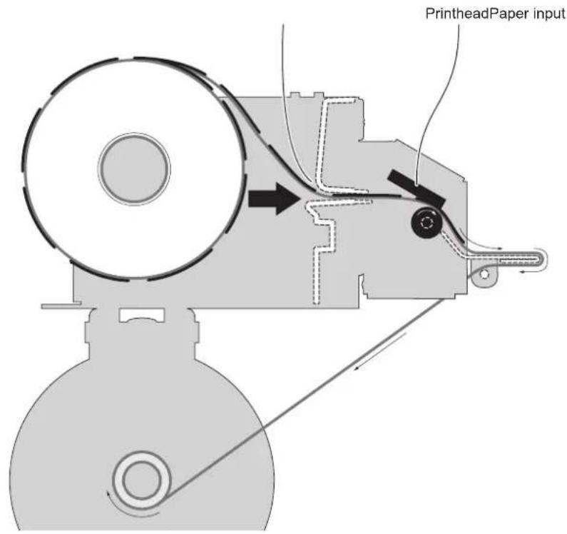
The device performs the label printing.
2
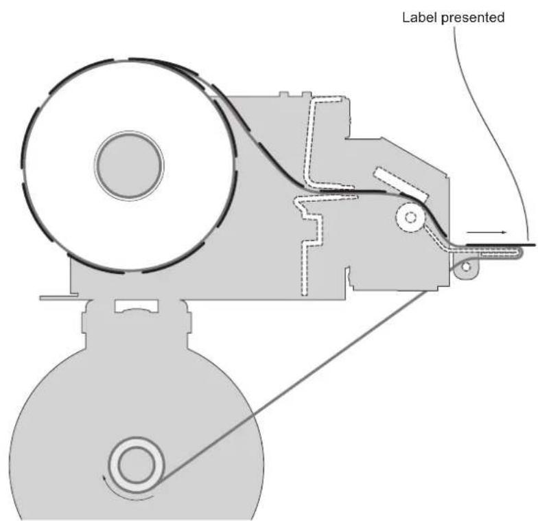
When printing ends, the device presents the label printed on the output peeler.
3
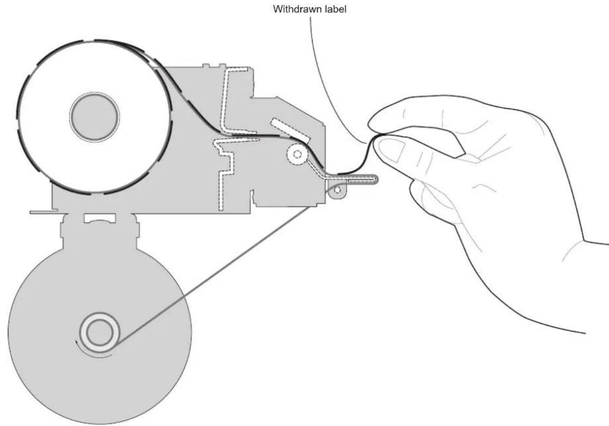
The user withdraws the printed label.
1
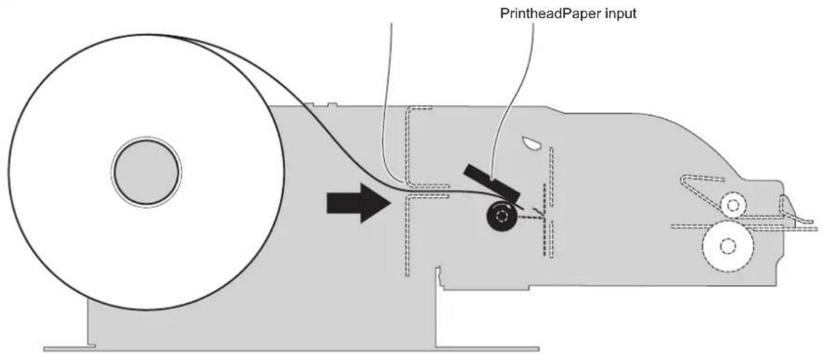
The device starts the ticket printing.
2
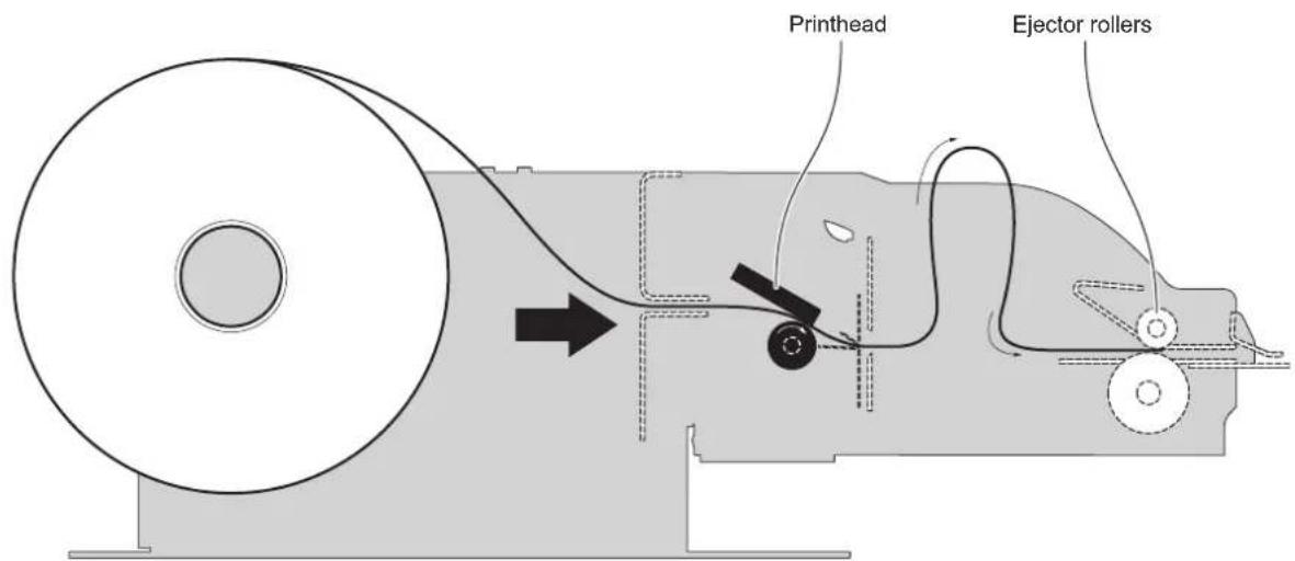
The ticket advances ahead to the ejector and is caught between the ejector rollers. The printed part of ticket is collected into the ejector group while the device continues printing.
3
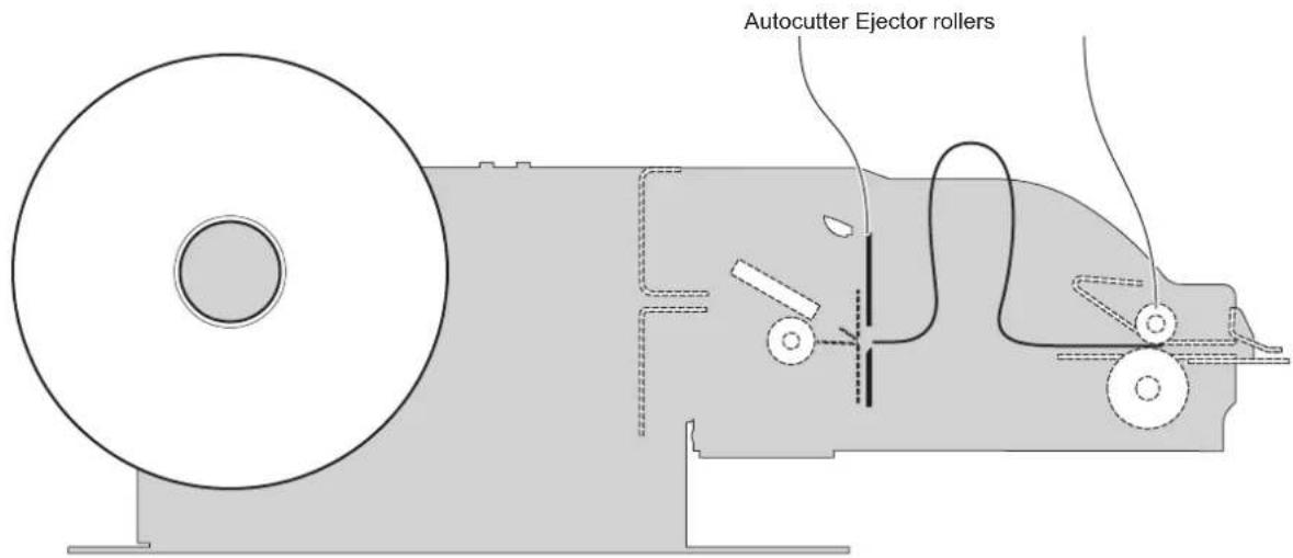
When printing ends, the device cuts the ticket printed.
Paper output Ticket presentedEjector rollers
4
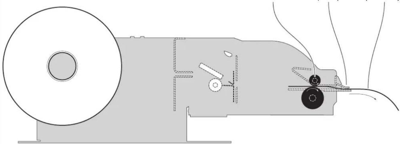
natural_image
Technical line drawing of a mechanical device with rollers and a belt, showing internal components and motion lines (no text or symbols)The device presents the ticket printed on the paper output.
5

natural_image
Simple analog clock face with hour and minute hands (no numbers or text)The ticket is waiting on the paper mouth for a preset period of time.
6
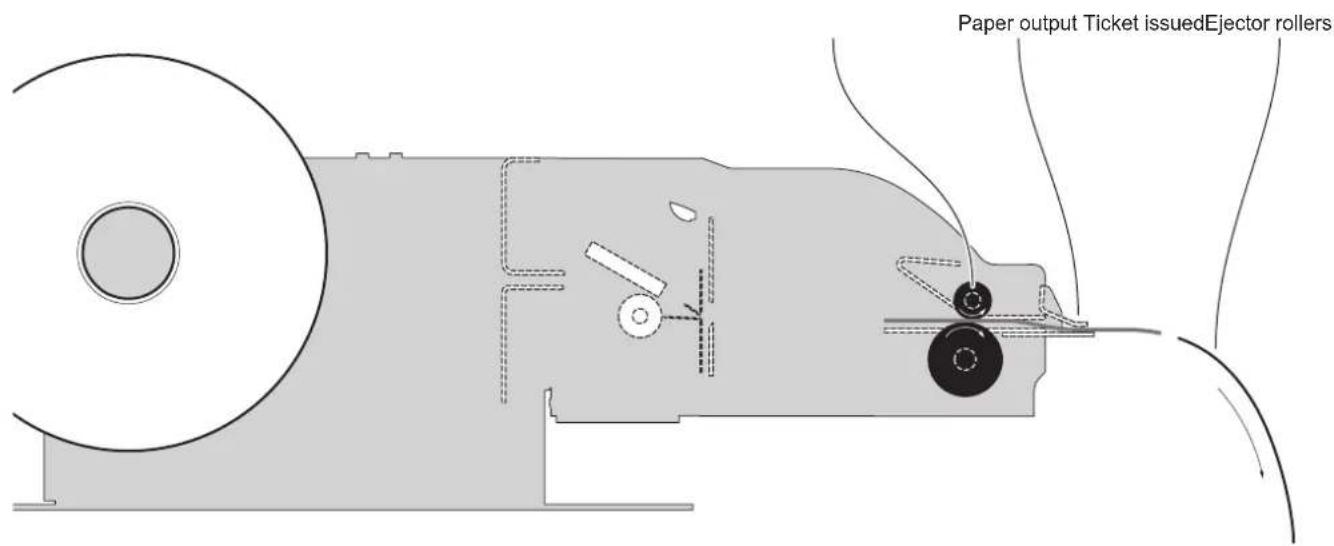
The device ejects the ticket.
NOTE: To enable this issuing mode, you need to correctly set the operation mode of the ejector with the command 0x1D 0x65 (see commands manual) and the setup parameter "Automatic Ejecting" (see chapter 6).
1
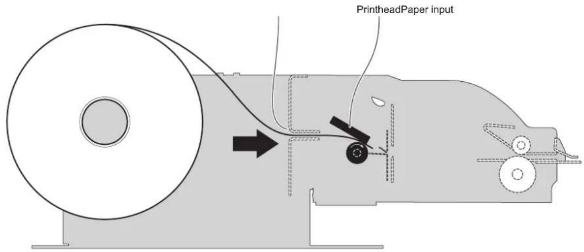
The device starts the ticket printing.
2
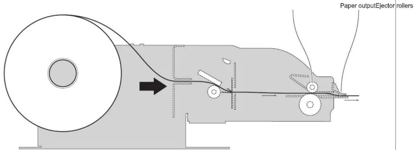
The ticket goes beyond the ejector rollers and stanrts to come out of the paper output.
3
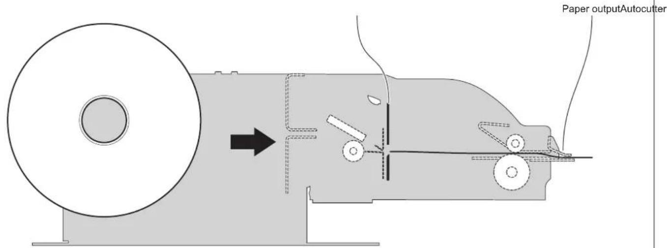
When printing ends, the device cuts the ticket printed.
4
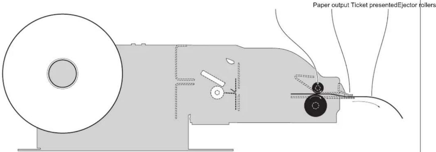
The device presents the ticket printed on the paper output.
5

natural_image
Simple analog clock face with hour and minute hands (no numbers or text)The ticket is waiting on the paper mouth for a preset period of time.
6
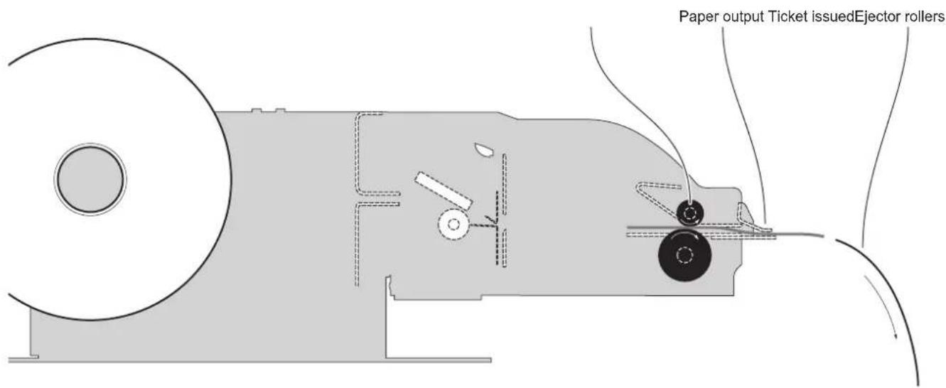
The device ejects the ticket.
NOTE: To enable this issuing mode, you need to correctly set the operation mode of the ejector with the command 0x1D 0x65 (see commands manual) and the setup parameter "Automatic Ejecting" (see chapter 6).
6 CONFIGURATION
6.1 Configuration by keys
To enter the configuration mode and print a setup report with the operating parameters of the device, proceed as follows.
1
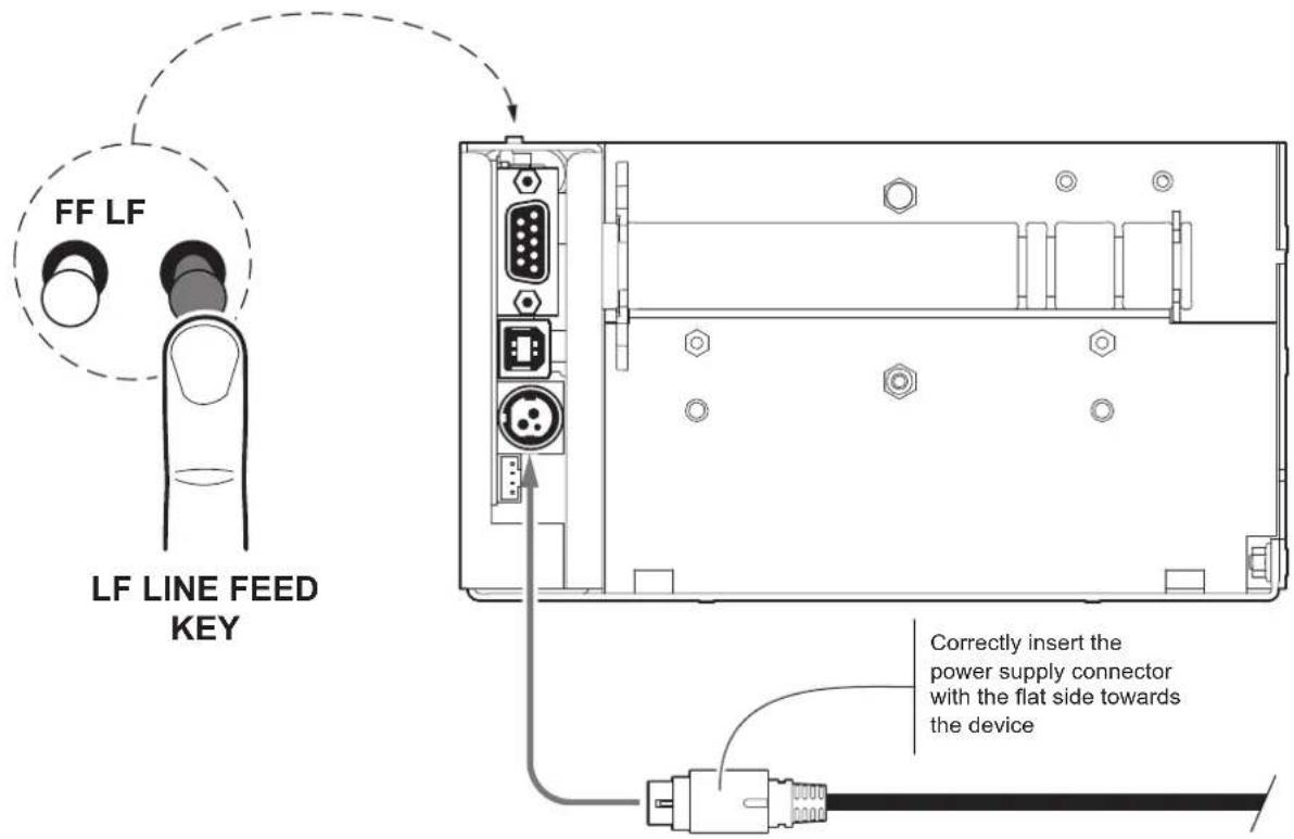
While pressing the LF LINE FEED key, switch on the device by connecting the power supply cable.
2
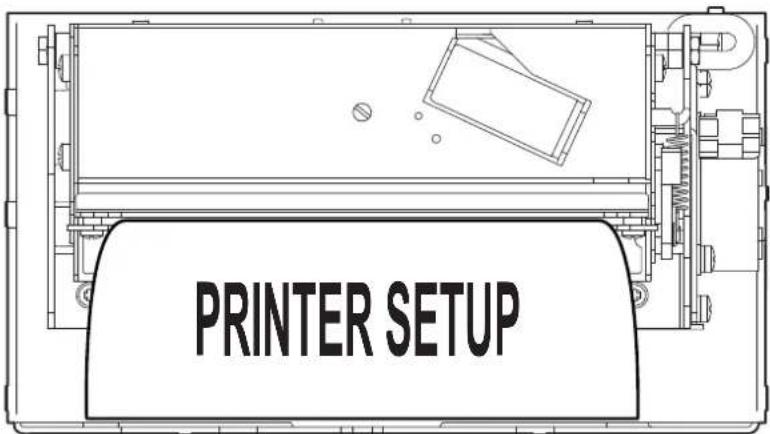
The device prints the report with the settings parameters. Follow the instruction printed on paper to proceed with configuration procedure.
The following figure shows the setup report of the device. The shown values for parameters are sample values; for the list and the description of device parameters see the following paragraphs.
![DEVICE NAME AND FIRMWARE MODULES RELEASE { SCODE. - rel 1.00 DCODE. - rel 1.00 FCODE. - rel 1.00 PRINTER SETTINGS PRINTER TYPE ...... PRINTING HEAD TYPE.... INTERFACE .......USB PROGRAM MEMORY TEST....OK DYNAMIC RAM TEST....OK EXTERNAL MEMORY TEST ....OK CUTTER TEST....OK HEAD VOLTAGE [V] = 24.12 HEAD TEMPERATURE [°C] = 24 POWER ON COUNTER = 4 PAPER PRINTED [cm] = 40 CUT COUNTER = 1 DEVICE CONFIGURATION PARAMETERS { Printer Emulation....: CUSTOM/POS RS232 Baud Rate....: 115200 bps RS232 Data Length....: 8 bits/chr RS232 Parity....: None RS232 Handshaking....: Hardware Busy Condition....: RxFull USB Class....: Printer USB Address Number....: 0 Print Mode....: Normal Autofeed....: CR Disabled Chars / inch....: A=15 B=20 cpi Code Table [num]....: 00 Font Type....: International Speed / Quality....: High Speed Automatic Ejecting....: Disabled Print Width....: 112mm Panel Key....: Enabled Paper Threshold....: 60% Black Mark Position....: Enabled Black Mark Threshold....: 40% Black Mark Distance [mm]....: +00.0 PaperEnd Buffer Clear....: Disabled Print Density....: 0% KEYS FUNCTIONS { [ LF ] enter Printer Setup [ FF ] skip Setup }](/content/2026/05/957511/images/8520a8b7fe8c779d373945de898f2b2496d03ca65108bb0250463780e22d8d97.jpg)
6.2 Configuration by software
The setup parameters can be set by using the "PrinterSet" software tool available on www.custom4u.it.
For a detailed description of the device operating parameters see the following paragraphs.
To configure the device by software, proceed as follows:
1
natural_image
Line drawing of a laptop computer with blank screen and keyboard (no text or symbols)Connect the device to a PC directly (see paragraph 4.2), without using HUB devices.
2

natural_image
Pure electrical circuit lines without any symbolsStart "PrinterSet" software tool.
3
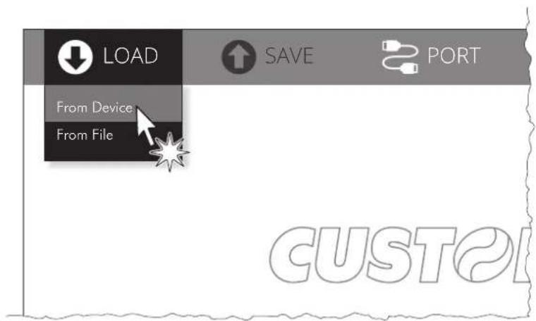
Click on LOAD > FROM DEVICE and select the device connected to the PC.
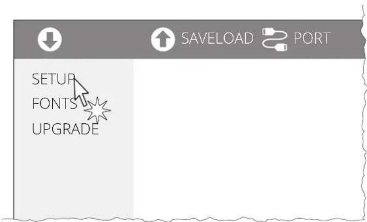
Click on SETUP to access the operating parameters of the device to be configured.
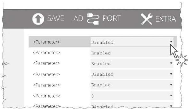
Make the desired changes to the device operating parameters.
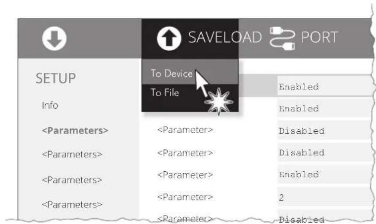
Click on SAVE > TO DEVICE to make the changes made effective.
ATTENTION: During saving, it is strongly discouraged to disconnect the communication cable or to remove the power supply of the PC or the device.
6.3 Configuration by file
The setup parameters can be set by editing the "Setup.ini" file stored on the Flash Drive of the device. Proceed as follows:
1

Enter setup
Enter the configuration procedure by keys (see paragraph 6.1) or by software (see paragraph 6.2).
2
ter> <value
USB Class ....: Mass Storage
<p
Check that the "USB Class" parameter is set to "Mass Storage".
Otherwise, this configuration mode is not available.
3
USB
flowchart
graph TD
    A["Laptop with monitor icon"] --> B["Server Icon"]
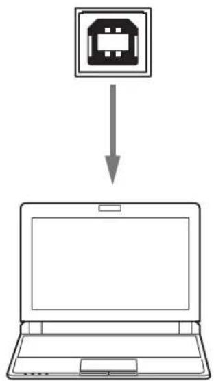
Plug the device to a Personal Computer via USB.
4
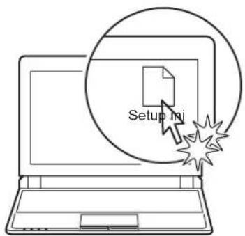
Enter the Flash drive of the device and edit the "Setup.ini" file.
The "Setup.ini" file is a configuration file that contains all the configurable parameters listed in text format and divided into some sections (indicated between square brackets). For each parameter, you find the parameter name followed by the value currently set and then the available values listed with a reference number. The reference number marked with the symbol ‘*’ is the default one (see figure).
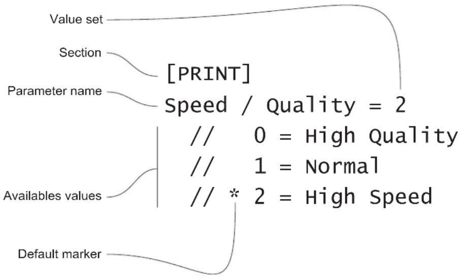
flowchart
graph TD
    A["Value set"] --> B["Section"]
    B --> C["[PRINT"]]
    C --> D["Parameter name"]
    D --> E["Speed / Quality = 2"]
    E --> F["// 0 = High Quality"]
    E --> G["// 1 = Normal"]
    E --> H["// * 2 = High Speed"]
    I["Availables values"] --> J["Default marker"]
To modify the parameter, change the numeric value after the parameter name or use the default value by typing "D". After editing device's parameter, simply save the "Setup.ini" file to make the modifies activated.
For a detailed description of the device operating parameters see the following paragraphs.
ATTENTION:
The change of value for the "USB Class" parameter may compromise the access to the Setup.ini file. Be careful to keep the "Mass Storage" value to allow a new access to the Flash Drive.
6.4 Device status
The device operating status is indicated in the configuration print-out in which, next to the name of the components displayed, the following information is given.
PRINTER TYPE device model
PRINTING HEAD TYPE printing head model
INTERFACE interface present
PROGRAM MEMORY TEST OK appears if functioning and NOT OK if faulty
DYNAMIC RAM TEST OK appears if functioning and NOT OK if faulty
EXTERNAL MEMORY TEST OK appears if functioning and NOT OK if faulty
CUTTER TEST OK appears if functioning and NOT OK if faulty
HEAD VOLTAGE voltage of the head
HEAD TEMPERATURE temperature of the head
POWER ON COUNTER number of power-ups made
PAPER PRINTED centimetres of paper printed
CUT COUNTER* number of cuts made
NOTE:
* : Parameter not valid for TPTCM60IIIL model.
6.5 Communication parameters
The device allows the configuration of the parameters listed in the following table.
The parameters marked with the symbol ^D are the default values.
Settings remain active even after the device has been turned off and they are stored in non-volatile memory.
RS232 BAUD RATE Communication speed of the serial interface:
| 9600 | 57600 |
| 19200 | 115200^D |
| 38400 |
Parameter valid only with serial interface.
RS232 DATA LENGTH Number of bit used for characters encoding:
| 7 bits/car |
| 8 bits/car ^D |
Parameter valid only with serial interface.
RS232 PARITY Bit for the parity control of the serial interface:
| None ^D = parity bit omitted |
| Even = even value for parity bit |
| Odd = odd value for parity bit |
Parameter valid only with serial interface.
RS232 HANDSHAKING Handshaking:
| Xon/Xoff = software handshaking |
| Hardware ^D = hardware handshaking (CTS/RTS) |
Parameter valid only with serial interface.
BUSY CONDITION Activation mode for the Busy signal:
| OffLine/ RxFull = Busy signal is activated when the device is both in OffLine status and the buffer is full |
| RxFull ^D = Busy signal is activated when the buffer is full |
Parameter valid only with serial interface.
USB ADDRESS NUMBER Numerical address code for the univocal identification of the USB device (in case of more than a USB device connected with the same PC):
| 0^D | 2 | 4 | 6 | 8 |
| 1 | 3 | 5 | 7 | 9 |
USB CLASS USB communication class definition.
| Printer ^D = setting the printer function |
| Mass Storage = setting the sharing mode from Mass Storage |
| Virtual COM = setting the USB port as a serial port |
6.6 Operating parameters
This device allows the configuration of the parameters listed in the following table.
The parameters marked with the symbol ^D are the default values.
Settings remain active even after the device has been turned off and they are stored in non-volatile memory.
PRINTER EMULATION Available emulations for the device:
CUSTOM/POS ^D
TPTCMII
CUSTOM TPT
PRINT MODE Printing mode:
Normal ^D = enables printing in normal writing way
Reverse = enables printing rotated 180 degrees
AUTOFEED Setting of the Carriage Return character:
CR disabled ^D = Carriage Return disabled
CR enabled = Carriage Return enabled
CHARS / INCH Font selection:
A = 11 cpi, B = 15 cpi
A = 15 cpi, B = 20 cpi ^D
CPI = Characters Per Inch
FONT SIZE Setting of the font size:
Font 8x16
Font 16x24 ^D
Font 24x32
Parameter used only with CUSTOM TPT emulation enabled.
JUSTIFICATION Type of justification:
Left ^D
Center
Right
Parameter used only with CUSTOM TPT emulation enabled.
CODE TABLE [NUM] Identifier number of the character code table to use.
See paragraph 9.8 to learn about the character tables corresponding to the identification numbers set with this parameter.
The character tables set with this parameter are the same set with the command 0x1B 0x74 (refer to the commands manual of the device).
The numeric value of the identifier is made up with the following two parameters for the setting of two digits for the tens and the units:
| Code Table [num x 10] | Setting the digit for tens: | ||||
| 0^D | 2 | 4 | |||
| 1 | 3 | 5 | |||
| Code Table [num x 1] | Setting the digit for units: | ||||
| 0^D | 2 | 4 | 6 | 8 | |
| 1 | 3 | 5 | 7 | 9 | |
FONT TYPE Setting of the font type:
International ^D = enables the use of the 256 characters font tables
Chinese GB18030 = enables the use of the chinese extended font GB18030
Korean CP949 = enables the use of the korean font CP949
SPEED / QUALITY Setting of printing speed and printing quality:
High Quality
Normal
High Speed ^D
AUTOMATIC EJECTING Setting of the automatic ejecting function of the last printed thicket in presentation mode:
Disabled ^D = ejecting function disabled
Enabled T.out 5s = the ticket is ejected after 5 seconds from the end of printing
Enabled T.out 10s = the ticket is ejected after 10 seconds from the end of printing
Enabled T.out 15s = the ticket is ejected after 15 seconds from the end of printing
Enabled T.out 20s = the ticket is ejected after 20 seconds from the end of printing
Enabled T.out 30s = the ticket is ejected after 30 seconds from the end of printing
Enabled T.out 40s = the ticket is ejected after 40 seconds from the end of printing
Enabled T.out 60s = the ticket is ejected after 60 seconds from the end of printing
Enabled T.out 2m = the ticket is ejected after 2 minutes from the end of printing
This parameter is printed only with TPTCM60III EJC, TPTCM112III EJC and TPTCM112III EJC 300 DPI.
PRINT WIDTH Printing area width:
76 mm 86 mm 96 mm
78 mm 88 mm 98 mm
80 mm 90 mm 100 mm
82 mm 92 mm 102 mm
84 mm 94 mm 104 mm D
This parameter is valid only for TPTCM112III EJC and TPTCM112III EJC 300 DPI.
PANEL KEY Panel key management:
| Disabled = Panel key disabled. Enabled ^D = Panel key enabled. | |||
| PAPER THRESHOLD | Threshold value (in percent) for the recognition of paper presence by the paper presence sensor: | ||
| 30% | 60% | 90% | |
| 40% | 70% | ||
| 50% ^D | 80% | ||
| PAPEREND BUFFER CLEAR | Cleaning mode of data in receive buffer, if the printing is stopped due to lack of paper: | ||
| Disabled ^D = Data remain in the receive buffer. When the paper runs out, the device keeps the remaining data in receive buffer and prints the remaining portion of ticket after that the new paper is loaded. Enabled = When the paper runs out, all data in the receive buffer are deleted. | |||
| PRINT DENSITY Adjusting the printing density: | |||
| -25% | 0 ^D | +25% | |
| -12% | +12% | ||
| The print quality is strongly influenced by the type of chemical treatment and the type of storage to which the thermal paper has been subjected, as well as by the weight of the same. It may therefore necessary to act on this parameter to obtain the desired print quality. | |||
6.7 Alignment parameters
The device allows the configuration of the parameters listed in the following table.
The parameters marked with the symbol ^D are the default values.
Settings remain active even after the device has been turned off and they are stored in non-volatile memory.
| BLACK MARK POSITION | Black mark or gap alignment management: | |||||
| Disabled^D= alignment is not performed Enabled = alignment is performed | ||||||
| BLACK MARK THRESHOLD | Threshold value (in percent) for the recognition of the presence of notch by the notch sensor: | |||||
| 30% | 70% | |||||
| 40% | 80% | |||||
| 50% | 90% | |||||
| 60%^D | ||||||
| For TPTCM112III CL the default value is 40%. | ||||||
| If "Black Mark Position" parameter is disabled, this parameter is not printed. | ||||||
| BLACK MARK DISTANCE [mm] | "Black mark distance" is the minimum distance (in millimetres) between the upper edge of the ticket and the black mark (see chapter 7). | |||||
| from -19.9 mm to 99.9 mm (default = 0 mm) | ||||||
| If "Black Mark Position" parameter is disabled, the parameters for the "Black Mark Distance" are not printed. The numeric value of the distance is made up with the following four parameters for the setting of three digits (two for the integer part of the number, one for the decimal part and of the sign): | ||||||
| BLACK MARK DISTANCE SIGN | Sign setting: | |||||
| + D= positive distance- = negative distance | ||||||
| BLACK MARK DISTANCE [mm x 10] | Setting the digit for tens: | |||||
| 0^D | 2 | 4 | 6 | 8 | ||
| 1 | 3 | 5 | 7 | 9 | ||
| BLACK MARK DISTANCE [mm x 1] | Setting the digit for units: | |||||
| 0^D | 2 | 4 | 6 | 8 | ||
| 1 | 3 | 5 | 7 | 9 | ||
| BLACK MARK DISTANCE [mm x .1] | Setting the digit for decimals: | |||||
| 0^D | 2 | 4 | 6 | 8 | ||
| 1 | 3 | 5 | 7 | 9 | ||
6.8 Hexadecimal dump
This function is used for the diagnosis of the characters received from the communications port. Characters are printed as hexadecimal code and the corresponding ASCII code (see below). Each line is preceded by a counter in hexadecimal that indicates the number of bytes received.
During the startup, if you hold down the FEED key, the device enters the self-test routine and print the setup report. The device remains in standby until a key is pressed or characters are received through the communication port (Hexadecimal Dump mode). For each character sent, the ticket shows the hexadecimal value and the ASCII codes (if the characters are underlined, the receive buffer is full). Shown below is an example of a Hexadecimal Dump:
HEXADECIMAL DUMP
| 31 | 32 | 33 | 34 | 35 | ... | 12345 | ... |
| 39 | 30 | 31 | 32 | 33 | ... | 90123 | ... |
| 37 | 38 | 39 | 75 | 69 | ... | 789ui | ... |
| 68 | 6B | 6A | 73 | 64 | ... | hkjsd | ... |
| 73 | 64 | 66 | 6B | 6A | ... | sdfkj | ... |
| 66 | 73 | 64 | 66 | 6B | ... | fsdfk | ... |
| 65 | 69 | 6F | 79 | 75 | ... | eioyu | ... |
| 6F | 72 | 69 | 75 | 77 | ... | oriuw | ... |
| 6F | 75 | 77 | 65 | 72 | ... | ouwer | ... |
| 77 | 65 | 72 | 69 | 6F | ... | werio | ... |
| 72 | 69 | 6F | 75 | 77 | ... | riouw | ... |
| 6B | 6C | 73 | 64 | 66 | ... | klsdf | ... |
| 64 | 66 | 6B | 73 | 64 | ... | dfksd | ... |
| 73 | 64 | 66 | 6B | 6A | ... | sdfkj | ... |
| 66 | 6B | F2 | 6A | 73 | ... | fk≥j | ... |
| 6A | 6B | 6C | 68 | jklh |
7 ALIGNMENT
Devices are provided with sensors for the alignment management in order to handle:
- rolls of tickets with pre-printed fields and a fixed length;
- rolls of labels with a fixed length.
The alignment notch may be formed by
- black mark printed on paper (see paragraph 9.7);
- gap between two labels (see paragraph 9.7);
All the alignment sensors are “reflection” sensors: this kind of sensor emits a band of light and detects the quantity of light reflected to it. The presence of the notch is therefore detected by the amount of light that returns to the sensor, considering that the light is reflected by the white paper and absorbed by the black mark.
The device that handle paper with labels, are provided with a fork sensor or a couple of facing sensors working in “transparence” mode: a beam of light is emitted by the transmitter sensor and the quantity of light which reaches the opposite receiver sensor is detected.
The presence of the gap between labels is detected evaluating the amount of light that arrives to the opposite sensor, considering that the white paper doesn't allow the beam of light to reach the receiver, whereas the translucent paper underlying (liner) lets the light to reach the receiver.
The following paragraphs show how to correctly set the configuration parameters of device in order to assure the alignment.
7.1 Enable alignment
TPTCM60IIIIL
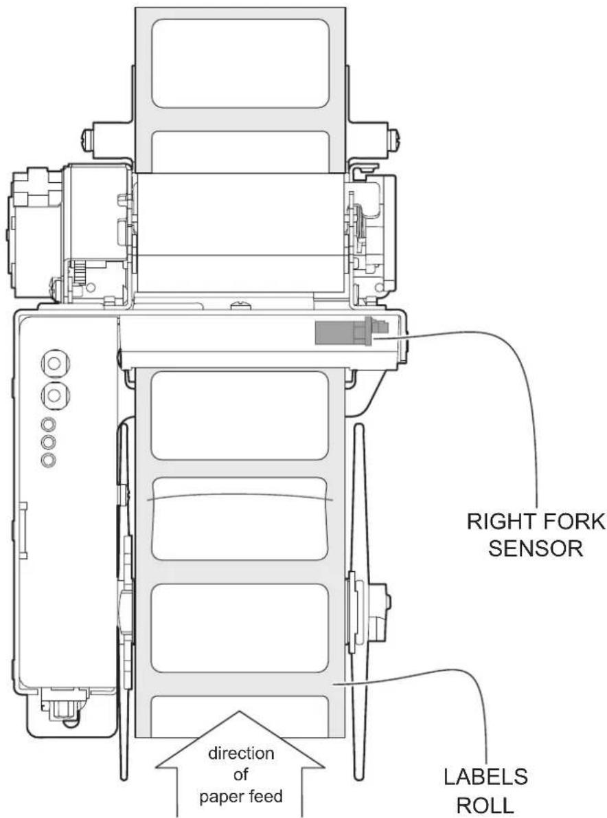
Device is provided with a fork sensors for alignment, placed on the right side of the paper input mouth:
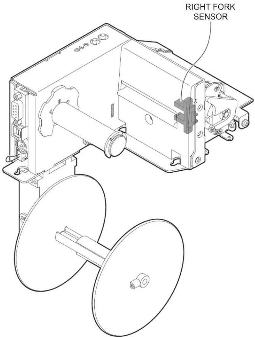
To guarantee the correct alignment, you must enable the parameter "Black Mark Position" during the setup procedure (see chapter 6).
If the alignment does not work properly, perform the labels gap detection sensor autoset procedure (see paragraph 7.3).
The following figure shows an example of paper with label usable with the device:
TPTCM112III, TPTCM112III STRONG CUT, TPTCM112III CL
The device is equipped with an alignment sensor that can be positioned in three different positions. In standard configuration, the sensor is positioned in position A.
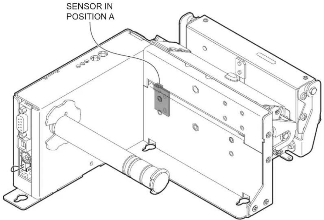
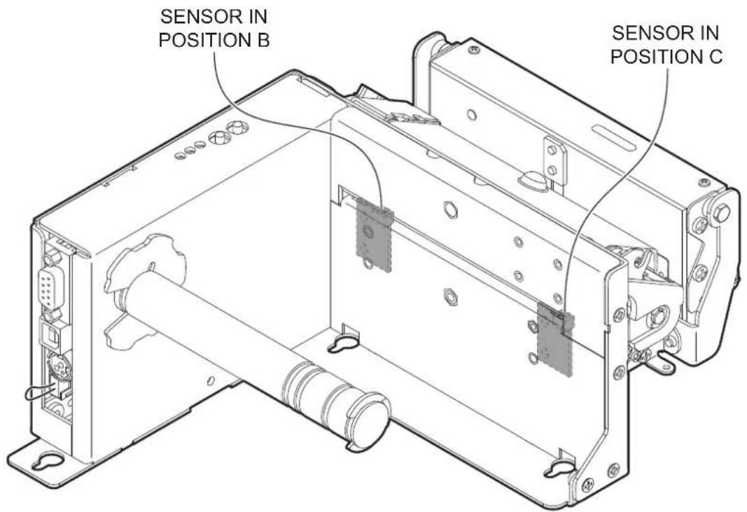
To place the sensor in positions B or C, proceed as follows.
1
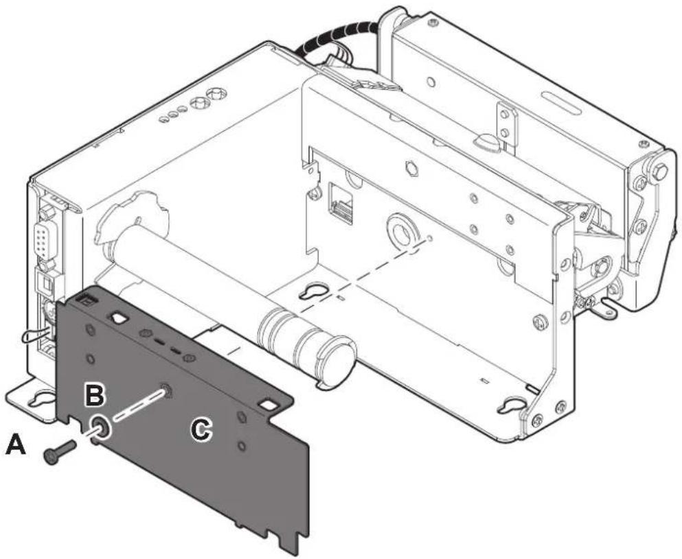
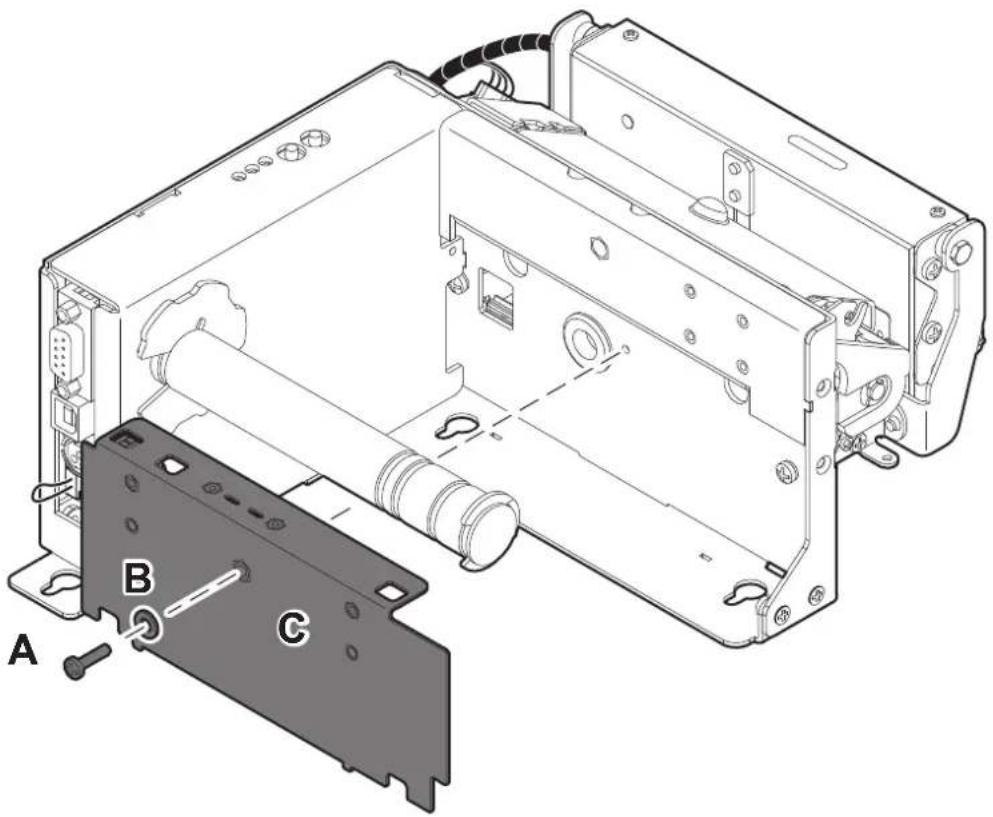
Unscrew the fixing screw A and remove the washer B. Move the lower paper guide away C being careful not to damage the cables.
2
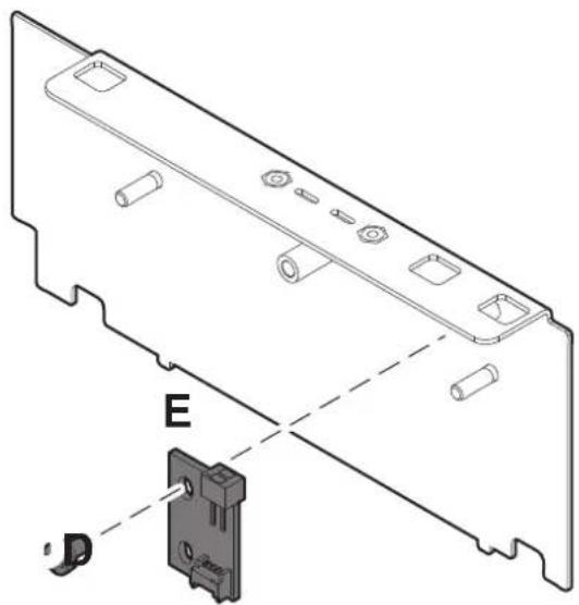
Unscrew the fixing screw D and remove the alignment sensor E.
3
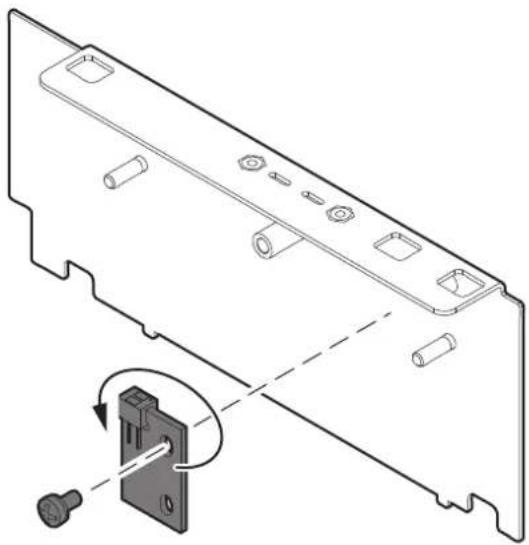
SENSOR IN POSITION B
natural_image
Technical line drawing of a mechanical component with a close-up inset showing a disassembly or assembly (no text or symbols present)To position the sensor in position B, rotate the sensor 180° and fix it in the previous position with the previously removed fixing screw. Make sure to match the pin of the paper guide with the hole in the alignment sensor board.
4
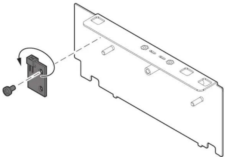
SENSOR IN POSITION C
natural_image
Technical line drawing of a computer monitor rear panel with a close-up view of the internal component (no text or symbols)To position the sensor in position C, rotate the sensor 180° and fix it in the position indicated with the previously removed fixing screw. Make sure to match the pin of the paper guide with the hole in the alignment sensor board.
5
natural_image
Technical diagram of an electronic device showing internal components and labeled parts (A, B, C), no readable text or symbols beyond labels.Reposition the lower paper guide C in its seat and fix it with the fixing screw A and the washer B.
The following figure shows an example of paper with black mark usable with the device:
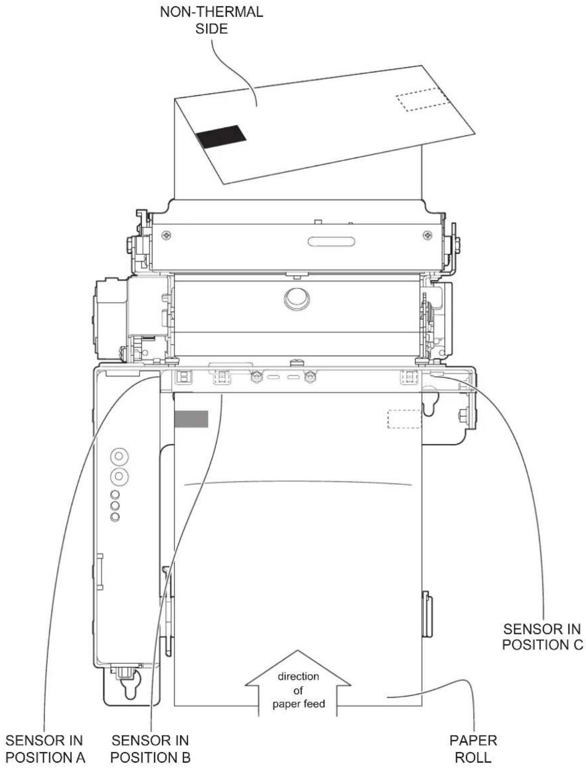
To guarantee the correct alignment, you must enable the parameter "Black Mark Position" during the setup procedure (see chapter 6).
TPTCM112IIIL
Device is provided with two sensor for alignment, placed as follows:
- a fixed sensor placed on the center, at the bottom of input paper mouth.
- a fixed sensor placed on the center, at the top of input paper mouth
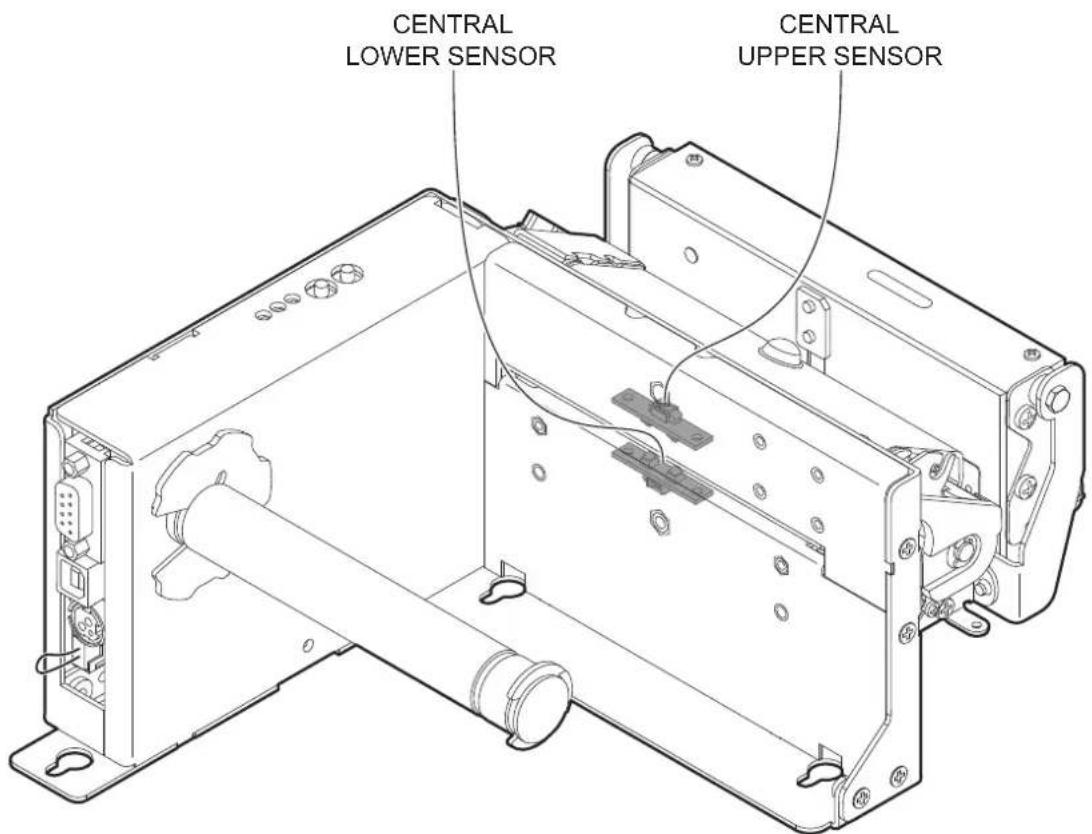
To guarantee the correct alignment, you must enable the parameter "Black Mark Position" during the setup procedure (see chapter 6).
If the alignment does not work properly, perform the labels gap detection sensor autoset procedure (see paragraph 7.3).
The following figure shows an example of paper with black mark usable with the device:
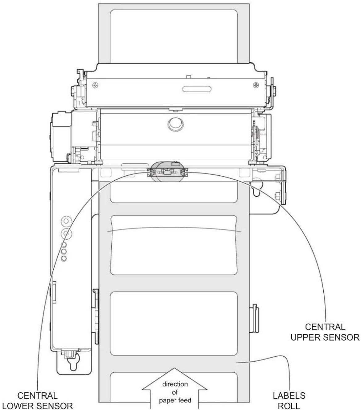
7.2 Calibration
The sensor calibration occurs automatically and consists in adjusting the quantity of light emitted to match the degree of whiteness of the paper used and the degree of black of the mark printed on paper.
The device automatically performs the self-calibration during the setup procedure only if the "Black Mark Position" parameter is set to a value other than "Disabled" (see chapter 6).
When self-calibration starts, the device performs some paper feeds and then it prints the calibration result and the value of the PWM duty-circle of the alignment sensor driver so that it can be perform an optimal notch detection:
Autosetting Notch : OK
PWM Duty Cycle : 85.3%
The “Autosetting Notch” parameter indicates the result of the self-calibration procedure; OK will appear if it has been successful, NOT OK will appear if the procedure has failed.
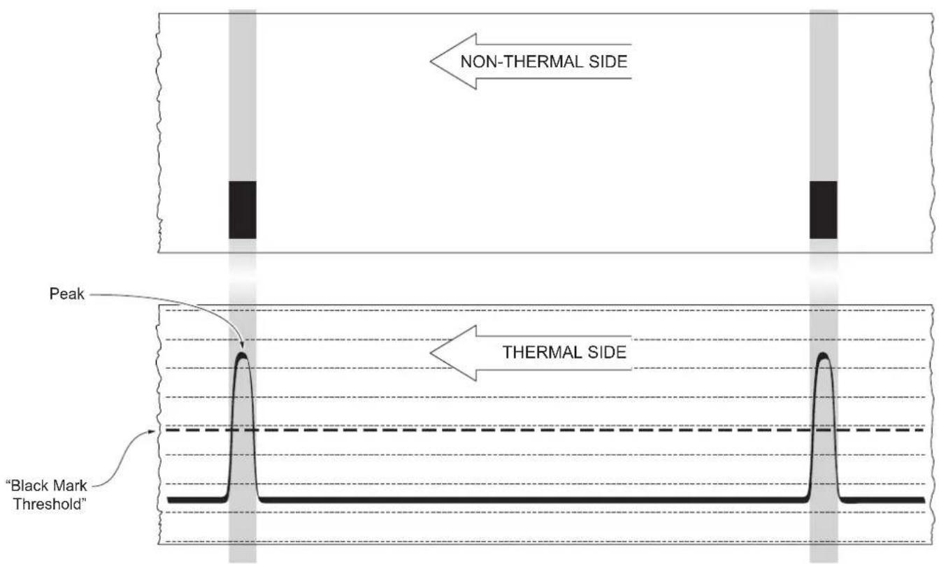
After the printing of the procedure result, the device offers the execution of the function of paper characterization “Characterize Paper” and the change of the “Black Mark Threshold” parameter which represents the detection threshold of the notch. Choosing the “Yes” value for the “Characterize Paper” parameter, the device prints a graphic representation (see following figures) of the outgoing voltage of the alignment sensor (expressed as a percentage) and the “Black Mark Threshold” value. This graphic representation is useful to set the most suitable value to assign to the “Black Mark Threshold” parameter and then to better identify the optimal threshold value which takes into account the variations of the signal and the small oscillations around zero.
The following figure shows an example of paper with the non-thermal paper printed with black marks: the outgoing voltage is constant while passing the white paper between two notches and presents a peak at each black mark. In this case, the optimal value for the "Black Mark Threshold" parameter is placed about half of the peak.
The following figure shows an example of paper with the non-thermal paper printed with black marks and other graphics (for example, a barcode): the outgoing voltage is constant while passing the white paper between two notches, presents a peak at each black mark and presents some “noise” at each barcode. In this case, the optimal value for the “Black Mark Threshold” parameter is located about halfway between the peak value and the maximum value of the “noise”.
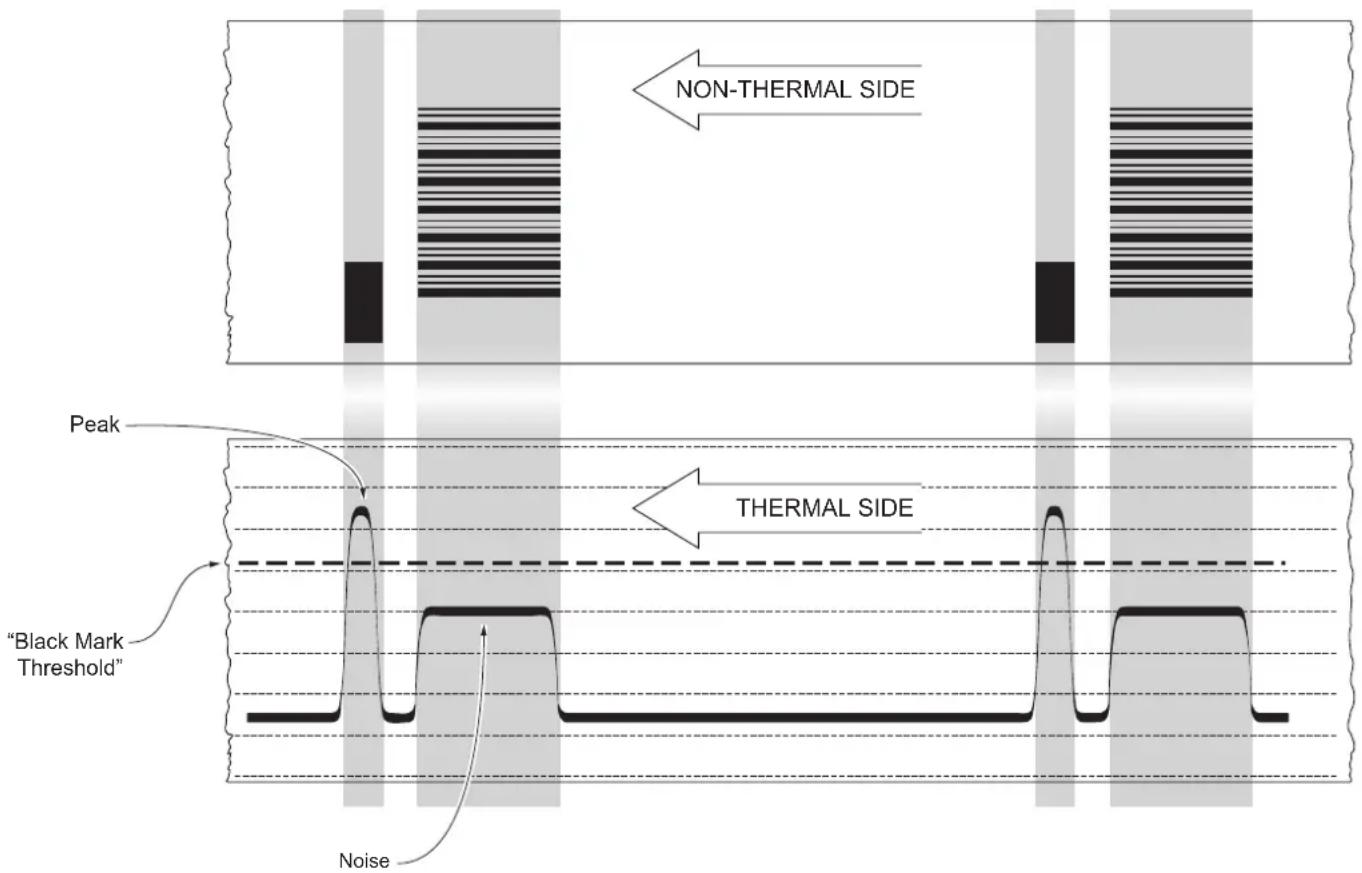
If the maximum value of “noise” read by the sensor is very close to the peak value, it might be difficult to place the value of the “Black Mark Threshold” at an intermediate point. In these cases, it is mandatory that the portion of paper between the point of printing end and the front notch is completely white (no graphics). In this way, the only next graphic detected by the sensor for alignment after the printing end will be the notch.
7.3 Labels gap detection sensor autoset procedure
TPTCM60IIIIL, TPTCM112IIIIL
1

Disconnect the power supply cable.
2
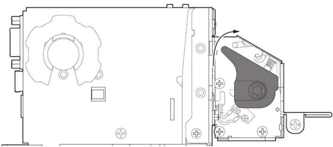
natural_image
Technical line drawing of a mechanical assembly with internal components and mounting holes (no text or symbols)Open the printhead by rotating the printhead lifting lever.
3
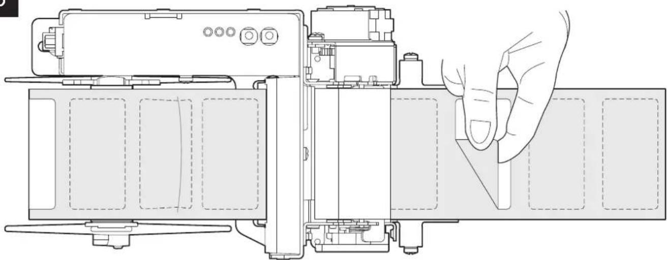
natural_image
Technical line drawing of a device interior showing internal components and a hand interacting with a screen (no text or symbols present)Remove all labels on the support near the paper inlet and bezel. There should be no labels under the printing mechanism.
4
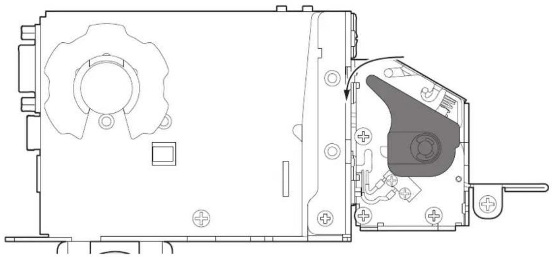
natural_image
Technical line drawing of a mechanical device showing internal components and assembly (no text or symbols)Close the printhead by rotating the printhead lifting lever.
5
Connect the power supply cable to the device.
6
natural_image
Line drawing of a laptop computer with blank screen and keyboard (no text or symbols)Connect the device to a PC directly (see paragraph 4.2), without using HUB devices.
7

natural_image
Pure electrical circuit symbol for a two-way push button (no text or labels)Start the "PrinterSet" software tool.
8
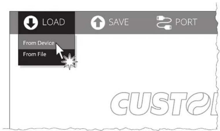
Click on LOAD > FROM DEVICE and select the device connected to the PC.
9
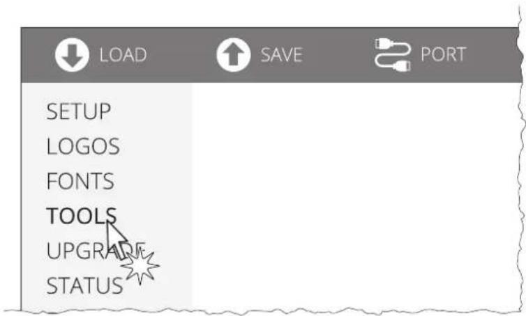
Click on TOOLS.
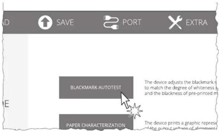
Click on BLACKMARK AUTOTEST.

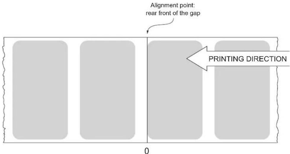
When you use paper with label, the "alignment point" is always meant as the label edge and match with the rear front of the gap between two labels. The gap width is automatically detected and measured by the sensors of the device.
The following figures show the simplified sections of the device models with the paper path and the distances (expressed in millimeters of theoretical paper path) between the alignment sensor, the printhead, autocutter (for models with presenter) and paper output.
TPTCM112III
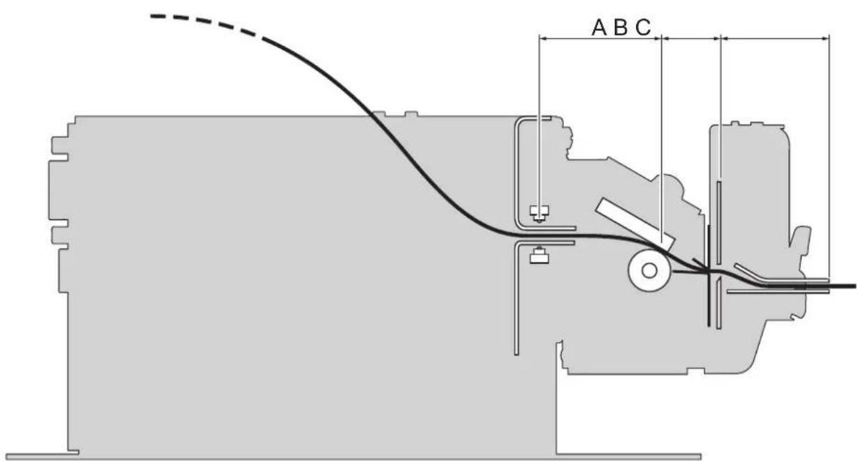
A = distance between printhead and alignment sensor = 34 mm
B = distance between printhead and autocutter = 17.4 mm
C = distance between autocutter and paper output = 31.4 mm
TPTCM60IIIIL
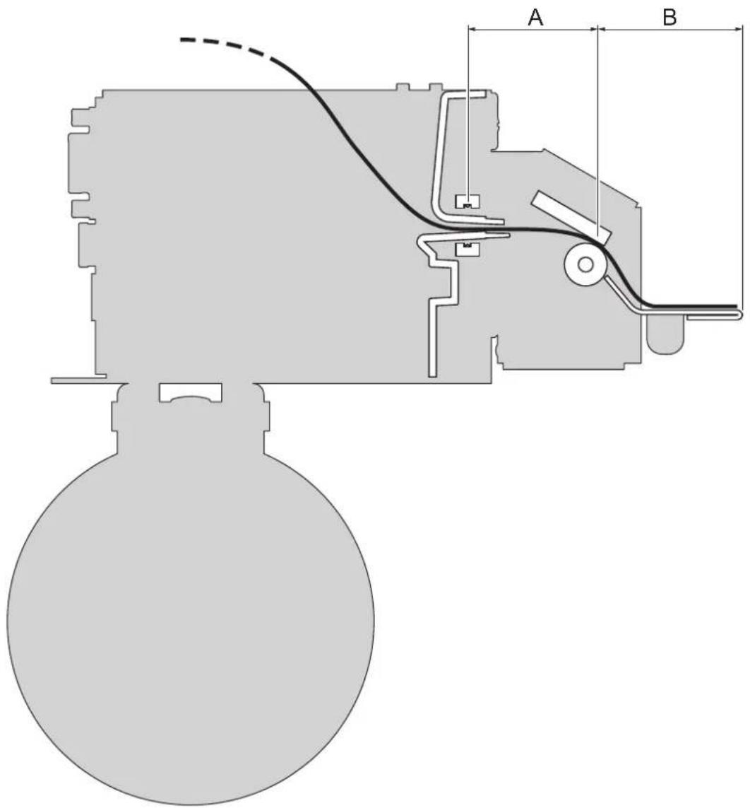
A = distance between printhead and alignment sensor = 36.5 mm
B = distance between printhead and peeler output = 47 mm
To enable the alignment management you need to enable the "Black Mark Position" as described in chapter 6.
TPTCM112III, TPTCM112III STRONG CUT, TPTCM112III CL
The "alignment point" is defined as the position inside the ticket to use for the notch alignment. The distance between the notch edge and the alignment point is defined as "Black Mark Distance".
Referring to the front of the notch, the value of "Black Mark Distance" value varies from 0 mm minimum and 99.9 mm maximum.
If the "Black Mark Distance" value is set to 0, the alignment point is set at the beginning of the notch.
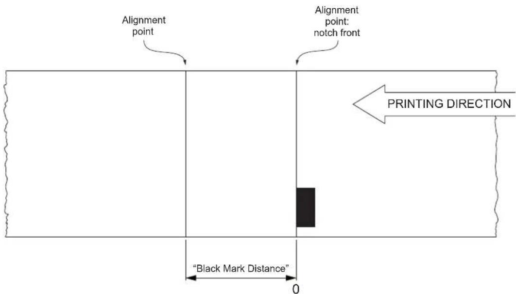
The following figures show the simplified sections of the device models with the paper path and the distances (expressed in millimeters of theoretical paper path) between the alignment sensor, the printhead, autocutter and paper output.
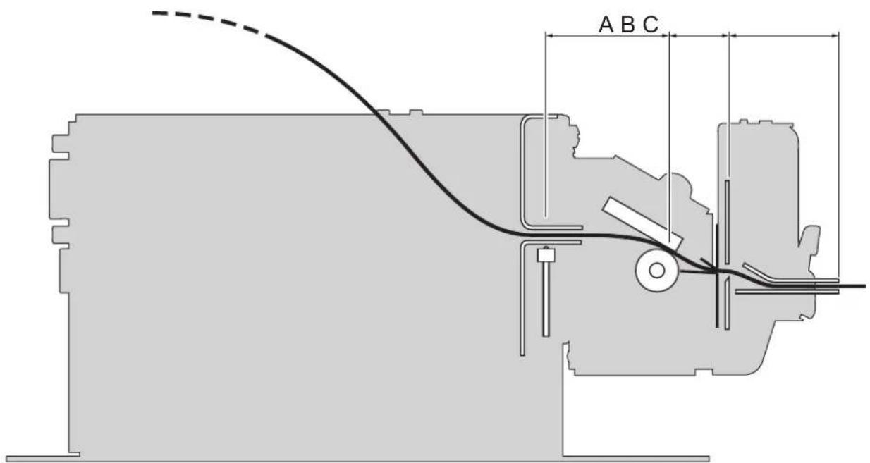
A = distance between printhead and alignment sensor = 34 mm
B = distance between printhead and autocutter = 17.4 mm
C = distance between autocutter and paper output = 31.4 mm
To define the alignment point you need to set the printer parameters that compose the numerical value of the "Black Mark Distance" parameter. (see paragraph 6.7).
For example, to set a black mark distance of 15 mm between the black mark and the alignment point, the parameters must be set on the following values:
Black Mark Distance Sign : +
Black Mark Distance [mm x 10] : 1
Black Mark Distance [mm x 1] : 5
Black Mark Distance [mm x .1] : 0
The "Black Mark Distance" parameter, may be modified as described in chapter 6.
7.5 Printing area
TPTCM60IIIIL, TPTCM112IIIIL
In order to issue labels correctly printed and to not overlay printing to the next label (that will make it useless for the next alignment), it is important to well calibrate the length of the printing area according to the label length.
The following figure shows an example of printed labels:
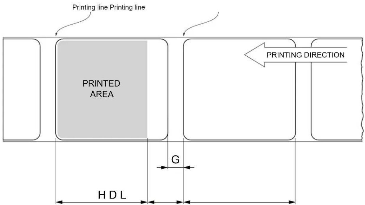
H Distance between the first and the last print line, called "Height of the printing area".
L "Label length".
G Distance between two consecutive labels, called "Gap length".
D Automatic feed for alignment at the next label edge.
To use all the labels on paper, you must comply with the following equation:
The height of the printing area (H) can be increased to make the progress on alignment (D) equal to the gap length but no further.
TPTCM112III, TPTCM112III STRONG CUT, TPTCM112III CL
In order to print ticket containing only one notch and to not overlay printing to a notch (that will make it useless for the next alignment), it is important to well calibrate the length of the printing area of ticket according to the inter-notch distance.
The following figure shows an example of tickets with "Black Mark Distance" set to 0:
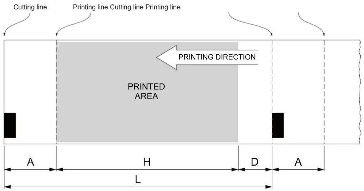
A "Non-printable area" = "Distance between autocutter/printhead"
where:
"Distance between autocutter/printhead" = 17.4 mm
H Distance between the first and the last print line, called "Hieght of the printing area".
L Distance between an edge of the black mark and the next one, called "Inter-black mark distance".
D Automatic feed for alignment at the next black mark.
To use all the notches on paper, you must comply with the following equation:
$$ \mathrm{H} + \mathrm{A} \leq \mathrm{L} $$
The height of the printing area (H) can be increased to make no progress on alignment (D) but no further.
8 MAINTENANCE
8.1 Paper jam
TPTCM60III EJC, TPTCM112III EJC, TPTCM112III EJC 300 DPI
1
natural_image
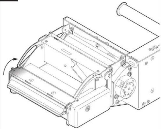
Technical line drawing of a mechanical device with internal components and mounting holes (no text or symbols)Lift and keep open the ejector cover.
2
natural_image
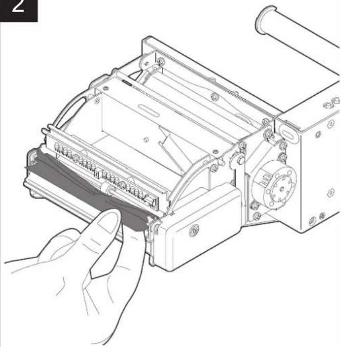
Illustration of a hand inserting a component into a device housing (no text or symbols visible)Remove the damaged paper and check the presence for paper scraps inside the ejector.
3
natural_image
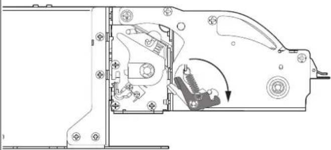
Technical line drawing of a mechanical assembly with no visible text or symbolsUnlock the ejector group by using the lever.
4
natural_image
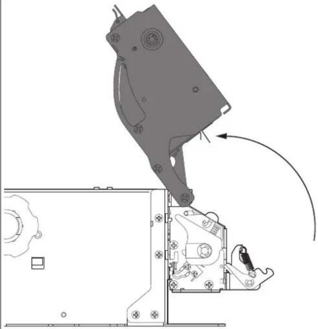
Technical line drawing of a mechanical assembly with a hand operating a component (no text or symbols present)Lift the ejector group to the maximum opening position.
5
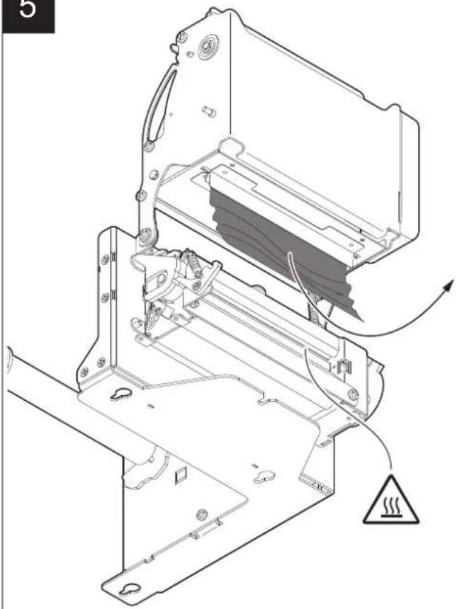
natural_image
Technical diagram of a mechanical device with internal components and a warning symbol (no text or labels present)Remove the damaged paper if present on the cutter input.
Be careful not to damage the connection cable or the printing mechanism
7
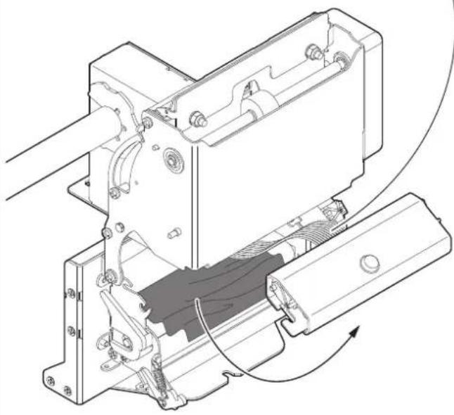
natural_image
Technical line drawing of a mechanical assembly with no visible text or symbolsRemove the damaged paper if present under the printing mechanism.
6
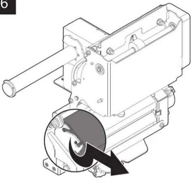
natural_image
Technical line drawing of a mechanical device with a magnified inset showing a circular component (no text or symbols)Unlock the printing mechanism as shown in figure.
1
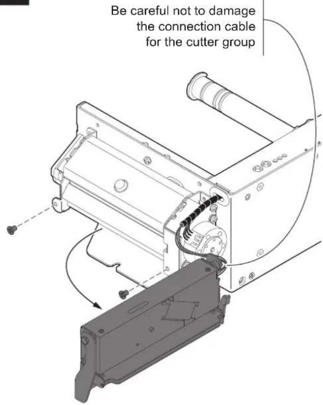
Unscrew the two fixing screws and remove the cutter group.
3
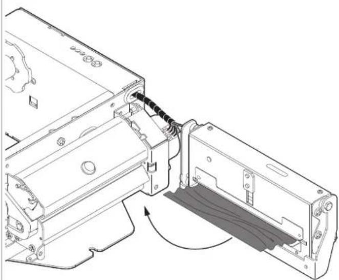
natural_image
Technical line drawing of a mechanical assembly with no visible text or symbolsRemove the damaged paper if present on the cutter input.
3
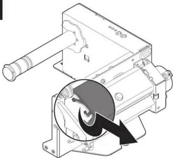
natural_image
Technical line drawing of a mechanical device with a magnified inset showing internal components (no text or symbols)Unlock the printing mechanism as shown in figure.
4
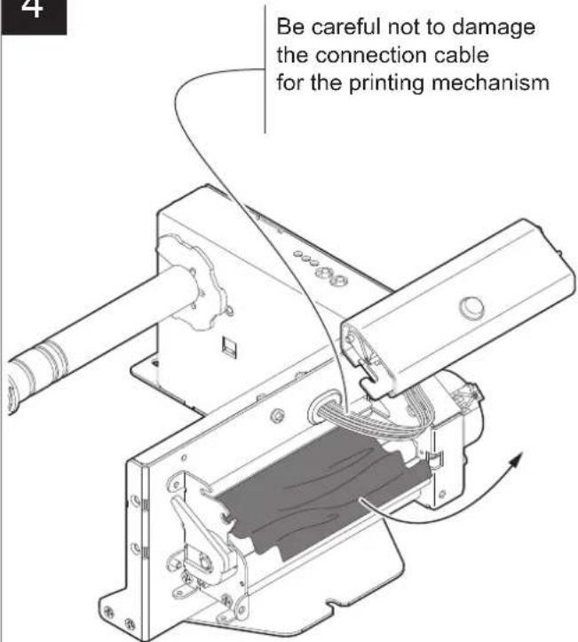
Remove the damaged paper if present under the printing mechanism.
8.2 Planning of cleaning operations
The regular cleaning of the device keeps the print quality and extends its life. The following table shows the recommended planning for the cleaning operations.
If you use the device in dusty environments, you must reduce the intervals between the cleaning operations.
For specific procedures, see the following pages.
EVERY PAPER CHANGE
Printhead Use isopropyl alcohol
Platen roller Use isopropyl alcohol
EVERY 5 PAPER CHANGES
Autocutter ^(1)
Use compressed air
Sensors Use compressed air
Ejector ^(2)
Use compressed air
AS NEEDED
Chassis Use compressed air or a soft cloth
Autocutter ^(3)
Use siliconic oil Do not use alcohol or any aggressive solvent
NOTES:
For some models is represented only the internal printer group.
(1) Only for TPTCM60III EJC, TPTCM112III, TPTCM112III 300 DPI, TPTCM112III STRONG CUT, TPTCM112III EJC, TPTCM112III EJC 300 DPI and TPTCM112III.
(2) Only for TPTCM60III EJC, TPTCM112III EJC and TPTCM112III EJC 300 DPI.
(3) Only for TPTCM112III CL.
8.3 Cleaning
For periodic cleaning of the device, see the instructions below.
Printhead - TPTCM60III EJC, TPTCM112III EJC, TPTCM112III EJC 300 DPI
1

Disconnect the power supply cable and lift the ejector group (see paragraph 8.1).
2
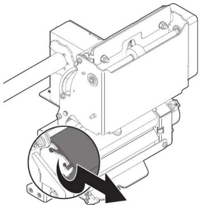
natural_image
Technical line drawing of a mechanical assembly with a magnified inset showing a circular component (no text or symbols)Unlock the printing mechanism as shown in figure.
3
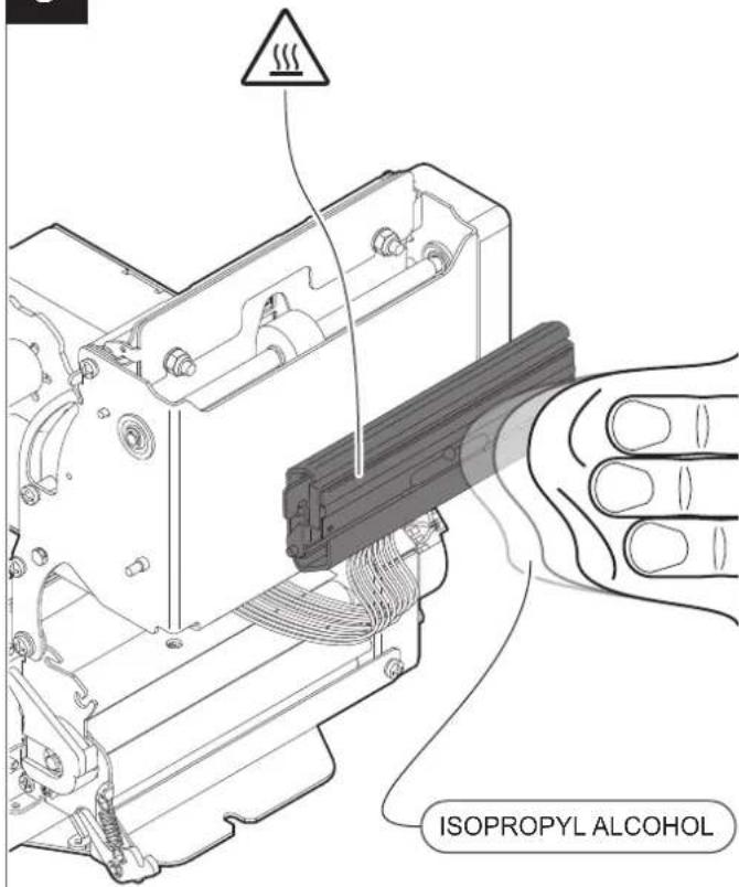
ATTENTION:
Do not use solvents, or hard brushes.
Do not let water or other liquids get inside the machine.


Clean the printhead by using a non-abrasive cloth moistened with isopropyl.
1

Disconnect the power supply cable.
2
Be careful not to damage the connection cable for the autocutter group
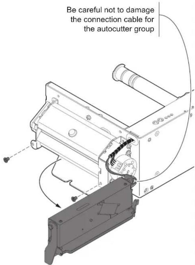
Unscrew the two fixing screws and remove the autoccutter group.
3
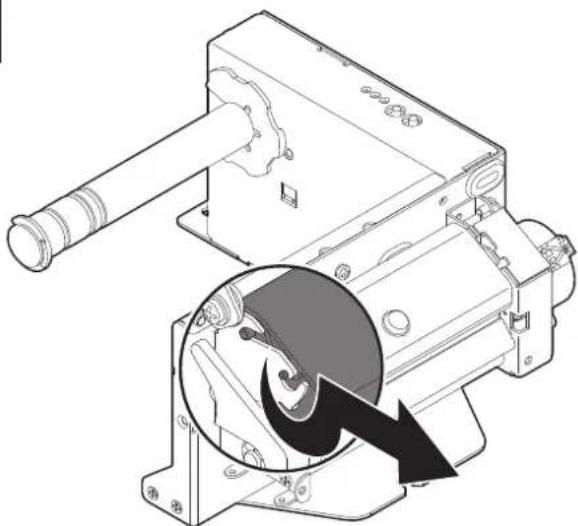
natural_image
Technical line drawing of a mechanical device with a magnified inset showing internal components (no text or symbols)Unlock the printing mechanism as shown in figure.
4
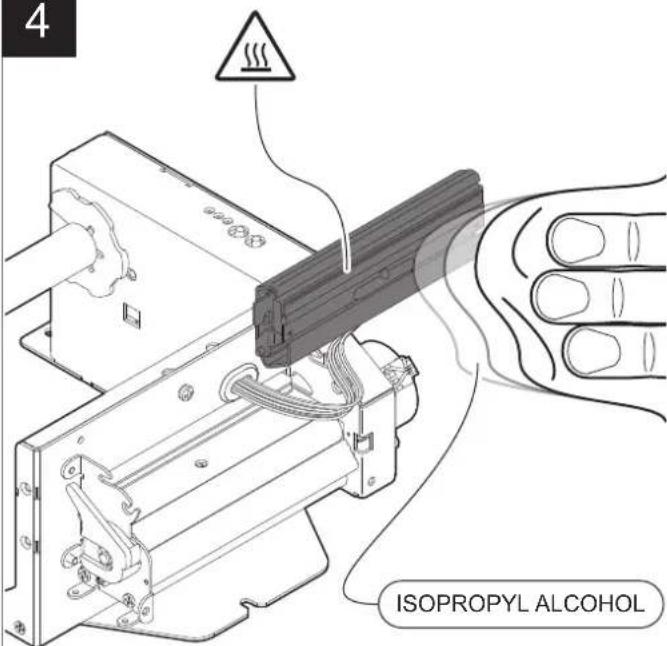
ATTENTION:
Do not use solvents, or hard brushes.
Do not let water or other liquids get inside the machine.


Clean the printhead by using a non-abrasive cloth moistened with isopropyl.
1

Disconnect the power supply cable.
2
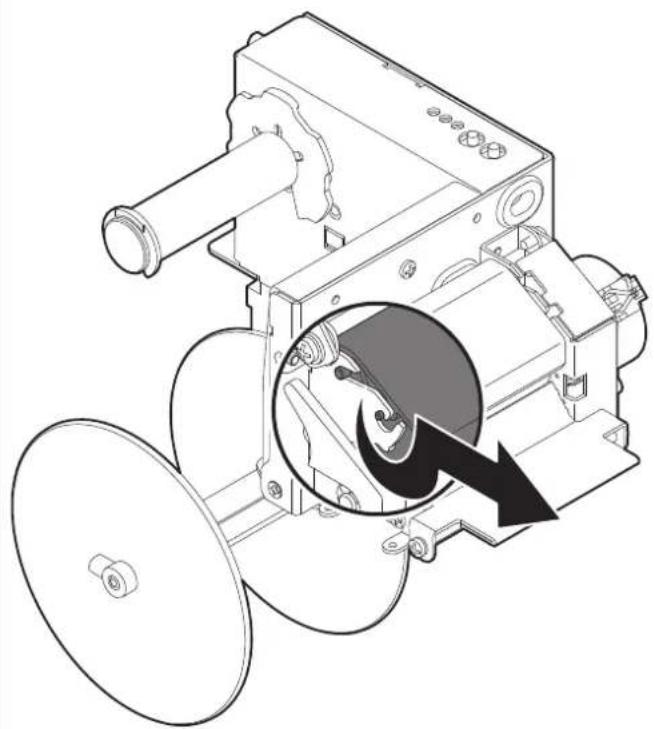
natural_image
Technical line drawing of a mechanical device with a magnified inset showing internal components (no text or symbols)Unlock the printing mechanism as shown in figure.
3
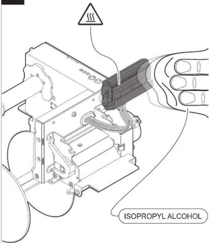
ATTENTION:
Do not use solvents, or hard brushes.
Do not let water or other liquids get inside the machine.


Clean the printhead by using a non-abrasive cloth moistened with isopropyl.
Platen roller
1

Disconnect the power supply cable.
2
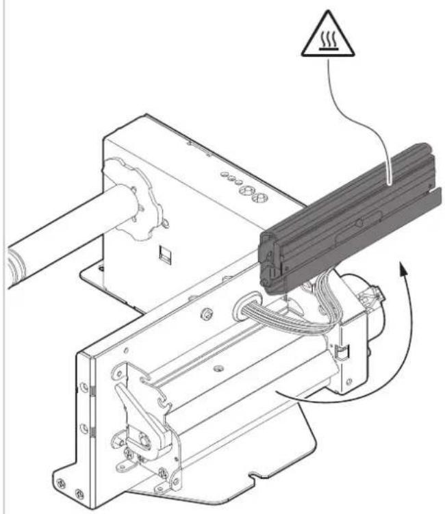
natural_image
Technical line drawing of a mechanical assembly with no visible text or symbolsUnlock the printing mechanism by following the specific procedure for each model as described in the previous paragraphs.
3
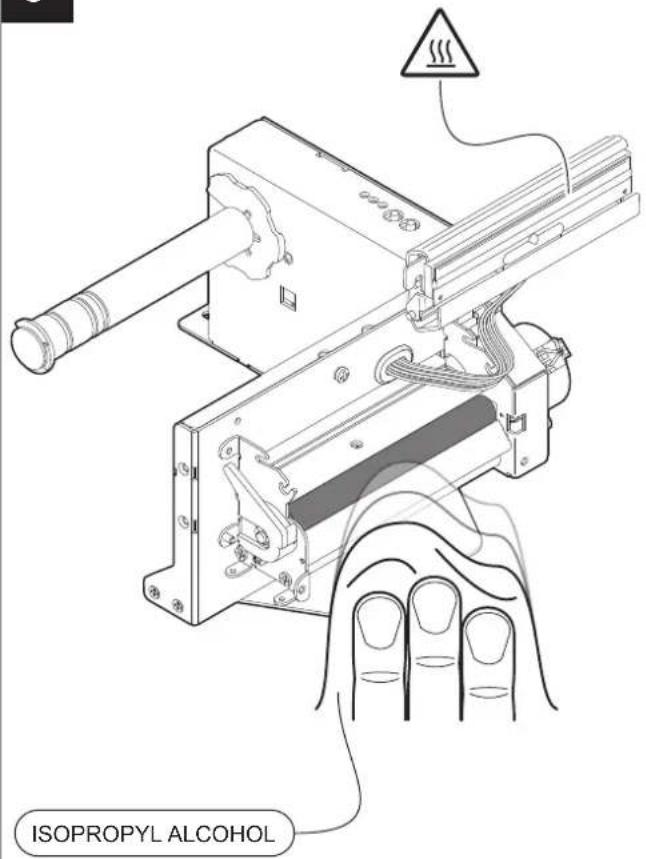
ATTENTION:
Do not use solvents, or hard brushes.
Do not let water or other liquids get inside the machine.


Clean the platen roller by using a non-abrasive cloth moistened with isopropyl alcohol.
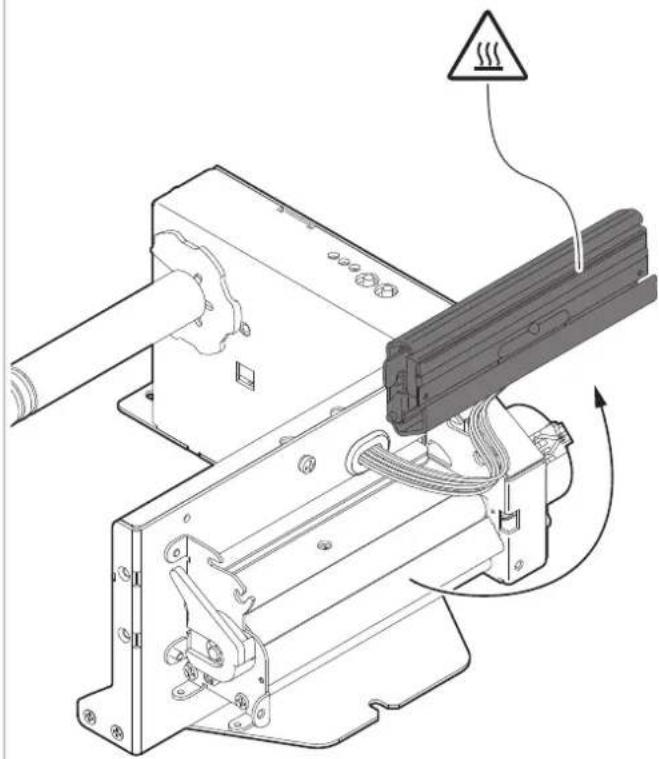
Sensor for paper presence in input
1

Disconnect the power supply cable.
2
natural_image
Technical line drawing of a mechanical assembly with no visible text or symbolsUnlock the printing mechanism by following the specific procedure for each model as described in the previous paragraphs.
3
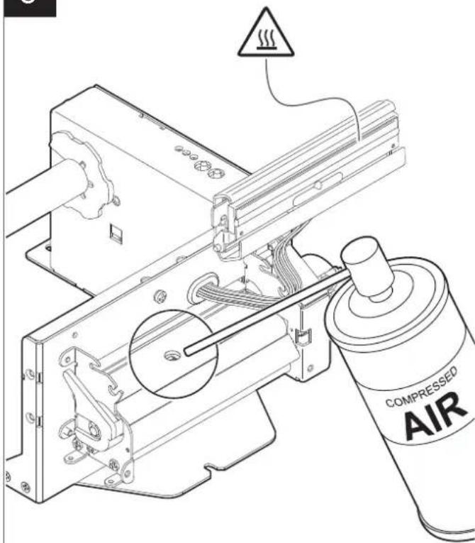
ATTENTION:
Do not use alcohol, solvents, or hard brushes.
Do not let water or other liquids get inside the device.


Clean the paper presence sensor in input by using compressed air.
1

Disconnect the power supply cable.
2
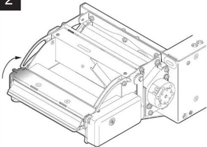
natural_image
Technical line drawing of a mechanical assembly with no visible text or symbolsLift and keep open the ejector cover.
3
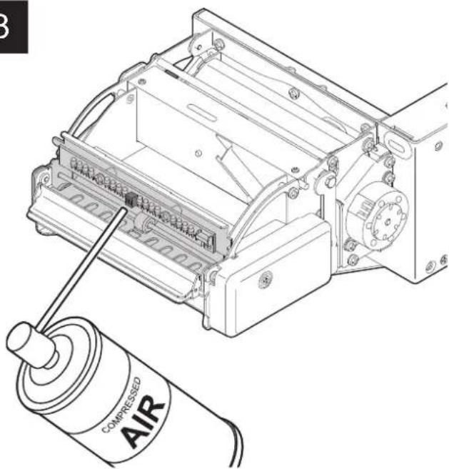
Clean the sensor for paper presence on output by using compressed air. Remove any scraps of paper and the accumulated paper dust inside the ejector.
4
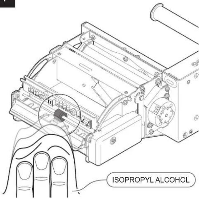
ATTENTION:
Do not use solvents, or hard brushes.
Do not let water or other liquids get inside the machine.


Clean the ejector roller by using a non-abrasive cloth moistened with isopropyl.
1

Disconnect the power supply cable.
2
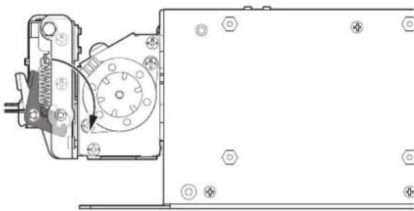
natural_image
Technical line drawing of a mechanical assembly with no visible text or symbolsUnlock the autocutter group by using the lever.
3
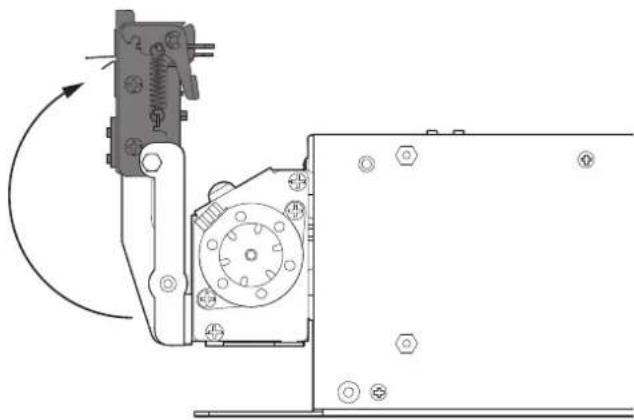
natural_image
Technical line drawing of a mechanical assembly with no visible text or symbolsLift the autocutter group.
4
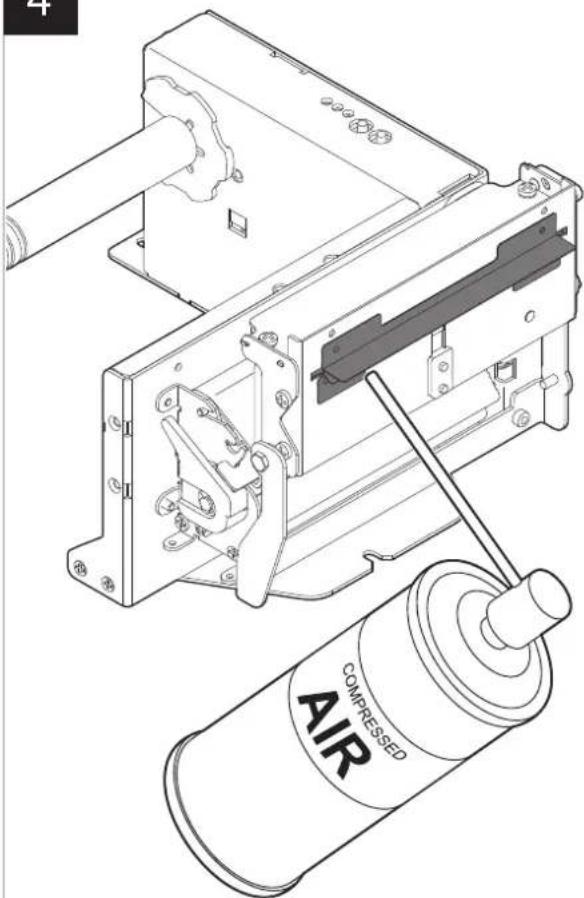
natural_image
Technical line drawing of an air compressor assembly with no visible text or symbolsATTENTION:
Do not use alcohol, solvents, or hard brushes.
Do not let water or other liquids get inside the device.


Remove any scraps of paper and the accumulated paper dust on the autocutter input by using compressed air.
Autocutter (TPTCM60III EJC, TPTCM112III EJC)
1

Disconnect the power supply cable and lift the ejector group (see paragraph 8.1).
2
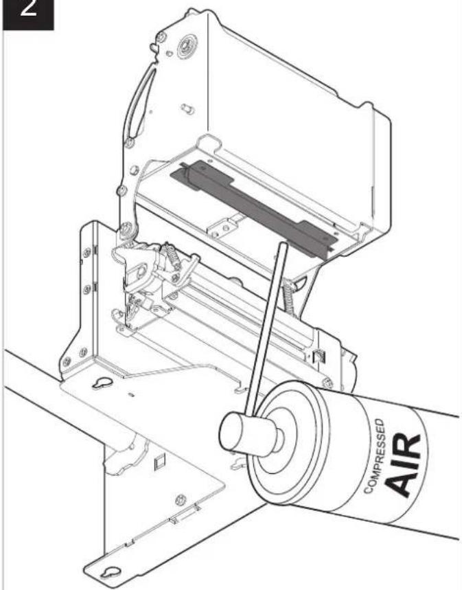
natural_image
Technical line drawing of an air compressor assembly with no visible text or symbolsATTENTION:
Do not use alcohol, solvents, or hard brushes.
Do not let water or other liquids get inside the device.


Remove any scraps of paper and the accumulated paper dust on the autocutter input by using compressed air.
Case
1

Disconnect the power supply cable.
2
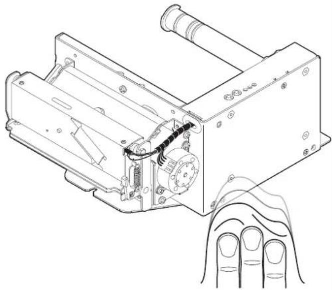
natural_image
Technical line drawing of a mechanical device with internal components and a hand gesture indicator (no text or symbols)ATTENTION:
Do not use alcohol, solvents, or hard brushes.
Do not let water or other liquids get inside the device.


To clean the device, use compressed air or a soft cloth.
8.4 Firmware upgrade
Firmware upgrade can be performed by using the "PrinterSet" software tool available on www.custom4u.it. To upgrade firmware, proceed as follows:
1
www.CUSTOM4U.it
Login to the website www.custom4u.it, type in the product code of the device and download the latest firmware release available.
2
natural_image
Line drawing of a laptop computer with blank screen and keyboard (no text or symbols)Connect the device to a PC directly (see paragraph 4.2), without using HUB devices.
3
Start the "PrinterSet" software tool.
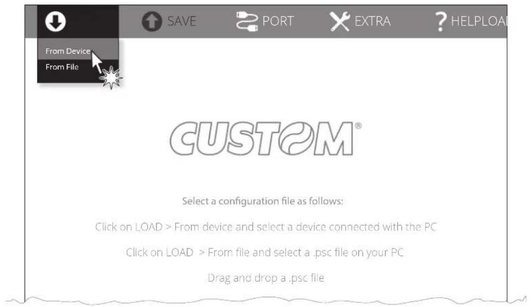
Click on LOAD > FROM DEVICE and select the device connected to the PC.
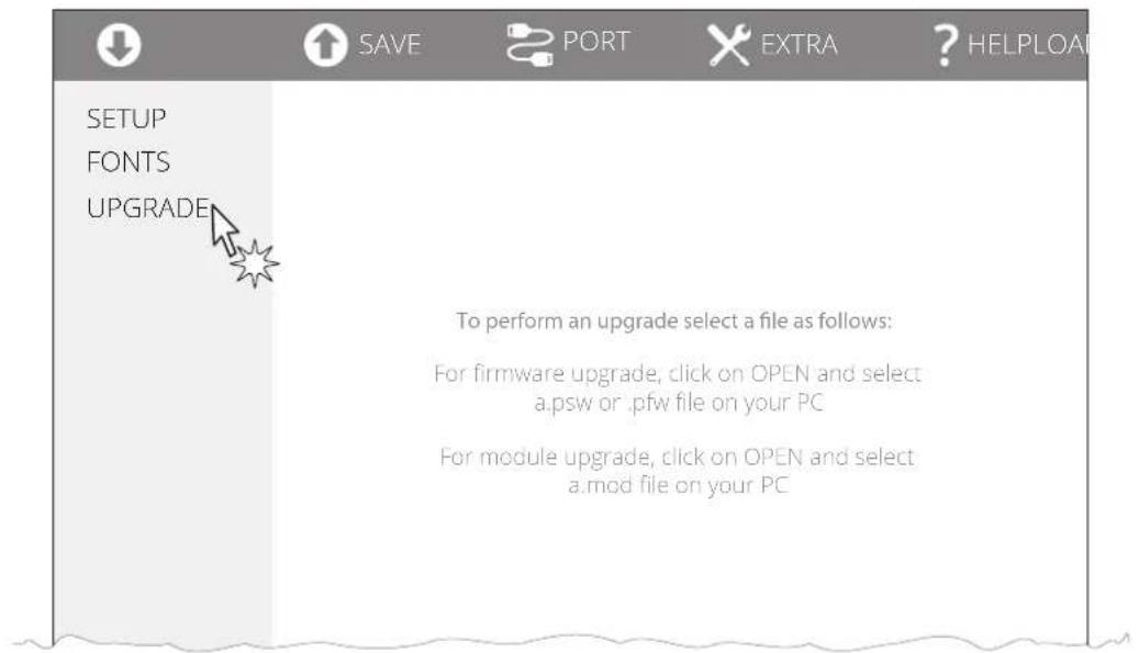
Click on UPGRADE and follow the instructions shown on the screen.
ATTENTION:
During saving, it is strongly discouraged to disconnect the communication cable or to remove the power supply of the PC or the device.
9 SPECIFICATION
9.1 Hardware specifications
| GENERAL | |
| Sensors | |
| TPTCM60III EJC | Head temperature, paper presence in input, print head lifted, low paper, paper presence on output, ejector position |
| TPTCM112III EJC | |
| TPTCM112III EJC 300 DPI | |
| TPTCM60IIIL | Head temperature, paper presence in input, print head lifted, low paper, fork sensor for gap between labels |
| TPTCM112III | |
| TPTCM112III 300 DPI | Head temperature, paper presence in input, print head lifted, low paper, left sensor for black mark, right sensor for black mark (optional) |
| TPTCM112III STRONG CUT | |
| TPTCM112III CL | |
| TPTCM112IIIL | Head temperature, paper presence in input, print head lifted, low paper, central detector (upper and lower) for gap between labels |
| Emulations CUSTOM/POS, TPTCMII, CUSTOM TPT | |
| Printing driver | Windows XPVISTA (32/64 bit)Windows 7 (32/64 bit)Windows 8 (32/64 bit)Windows 8.1 (32/64 bit)Windows 10 (32/64 bit)Self-installing driver for Virtual COM (32/64 bit)LinuxAndroid |
| INTERFACES | |
| USB port 12 Mbit/s | |
| RS232 serial port from 1200 bps to 115200 bps | |
| MEMORIES | |
| Receive buffer 16 kB | |
| Flash memory 1 MB internal + 4 MB external (of which 1 MB available for user) | |
| RAM memory 128 kB internal, 8 MB external | |
PRINTER
Resolution
TPTCM60III EJC
TPTCM60IIIL
TPTCM112III
TPTCM112III STRONG CUT
TPTCM112III EJC
TPTCM112IIIL
TPTCM112III CL
203 dpi (8 dot/mm)
TPTCM112III 300 DPI
TPTCM112III EJC 300 DPI
304 dpi (12 dot/mm)
Printing method Thermal, fixed head
Head life ^(1)
Abrasion resistance (2)
100 km (with recommended paper, 12.5% duty cycle)
Pulse durability 100 M (referred to each dot)
Printing width 80 mm
TPTCM60III EJC
TPTCM60IIIL
60 mm
TPTCM112III
TPTCM112III 300 DPI
TPTCM112III STRONG CUT
TPTCM112IIIL
TPTCM112III CL
104 mm
TPTCM112III EJC
TPTCM112III EJC 300 DPI
from 76 mm to 104 mm (2 mm step)
Printing method Normal, 90°, 180°, 270°
Printing format Height/Width from 1 to 8, bold, reverse, underlined, italic
Character font
54 character code tables (see paragraph 9.8), extended chinese GB18030-2000, korean PC949
Printable barcodes
Codabar, Code 32, Code 39, Code 93, Code 128, EAN-8, EAN-13, ITF, UPC-A, UPC-E, Data Matrix, PDF417, QRCode
Printing speed (1)(3)
High quality = 80 mm/s
Normal = 115 mm/s
High Speed = 140 mm/s
PAPER
Type of paper Thermal rolls, heat-sensitive side on outside of roll
Paper width
| TPTCM60III EJC | 60 mm ± 0.5 mm |
| TPTCM60IIIL | |
| TPTCM112III | |
| TPTCM112III STRONG CUT | 80 mm ± 0.5 mm |
| TPTCM112III 300 DPI | 86 mm ± 0.5 mm |
| TPTCM112III EJC | 100 mm ± 0.5 mm |
| TPTCM112III EJC 300 DPI | 112 mm ± 0.5 mm |
| TPTCM112III CL |
Paper weight
| TPTCM60III EJC | |
| TPTCM60IIIL | |
| TPTCM112III | |
| TPTCM112III 300 DPI | from 60 g/m^2 to 90 g/m^2 |
| TPTCM112III EJC | |
| TPTCM112III EJC 300 DPI | |
| TPTCM112IIIL | |
| TPTCM112III CL |
| TPTCM112III STRONG CUT from 60 g/m | ^2 to 130 g/m ^2 |
Paper thickness from 63 m to 100 m
| Recommended types of paper | KANZAN KF50 and KP460MITSUBISHI PF5067 and TL4000 |
External roll diameter ^(4)
| TPTCM60III EJC | (without optional paper roll holder) max. 90 mm(with optional paper roll holder) max. 160 mm |
| TPTCM60IIIL max. 90 mm | |
| TPTCM112IIITPTCM112III 300 DPITPTCM112III EJCTPTCM112III EJC 300 DPITPTCM112IIILTPTCM112III CL | (without optional paper roll holder) max. 120 mm(with optional paper roll holder) max. 160 mm |
Internal roll core diameter 25 mm (+ 1 mm)
Paper end Not attached to roll core
Core type Cardboard or plastic
LABELS (TPTCM60IIIL, TPTCM112IIIL, TPTCM112III CL)
Label type
Labels on roll
Thermal paper white (heat-sensitive side on outside of roll)
Paper weight 78 g/m
2
Paper thickness 0.085 mm
Paper adhesive Clear synthetic rubber adhesive for general purpose
Liner width
TPTCM60IIIL 60 mm ± 0.5 mm
TPTCM112IIIL 112 mm ± 0.5 mm
Liner weight 60 g/m
2
Liner thickness 0.055 mm
Liner trasparency Trasparency 47%
Liner total thickness 0.15 mm ± 10%
AUTOCUTTER
(TPTCM60III EJC, TPTCM112III, TPTCM112III 300 DPI, TPTCM112III STRONG CUT, TPTCM112III EJC,
TPTCM112III EJC 300 DPI, TPTCM112IIIIL, TPTCM112III CL)
Paper cut Total cut
Estimated life ^(1)
TPTCM60III EJC
TPTCM112III
TPTCM112III EJC
TPTCM112IIIL
TPTCM112III 300 DPI
TPTCM112III EJC 300 DPI
TPTCM112III STRONG CUT
1000000 cuts (with paper thickness 100 m, ambient temperature)
TPTCM112III CL 500000 cuts (with paper thickness 120 m, ambient temperature)
DEVICES ELECTRICAL SPECIFICATIONS
Power supply 24 Vdc ± 10%
Assorbimento medio (5)
TPTCM60III EJC TPTCM60IIIL 2.5 A
TPTCM112III
TPTCM112III 300 DPI
TPTCM112III STRONG CUT
TPTCM112III EJC
TPTCM112III EJC 300 DPI
TPTCM112IIIL
TPTCM112III CL
Assorbimento tipico ^(3)
TPTCM60III EJC TPTCM60IIIL 1.2 A
TPTCM112III
TPTCM112III 300 DPI
TPTCM112III STRONG CUT
TPTCM112III EJC
TPTCM112III EJC 300 DPI
TPTCM112IIIL
TPTCM112III CL
Standby consumption 50 mA
POWER SUPPLY ELECTRICAL SPECIFICATIONS code 963GE020000071 (optional for TPTCM60III EJC and TPTCM60IIIL)
Power supply voltage from 90 Vac to 264 Vac
Frequency from 47 Hz to 63 Hz
Output 24 V, 2.5 A
Power 60 W
POWER SUPPLY ELECTRICAL SPECIFICATIONS code 963GE020000106 (optional for TPTCM112III, TPTCM112III 300 DPI, TPTCM112III STRONG CUT, TPTCM112III EJC, TPTCM112III EJC 300 DPI, TPTCM112IIIIL, TPTCM112III CL)
Power supply voltage Auto Range, 90-264 Vac
Frequency from 47 Hz to 63 Hz
Output 24 V, 4.17 A
Power 100 W
ENVIRONMENTAL CONDITIONS
Operating temperature from 0^ C to +50^ C (6)
Relative humidity (RH) from 10% to 85% (w/o condensation)
Storage temperature from -20 °C to +70 °C
Storage relative humidity (RH) from 10% to 90% (w/o condensation)
NOTES:
(1): Respecting the regular schedule of cleaning for the device components.
(2): Damages caused by scratches, ESD and electromigration are excluded.
(3): Referred to a standard CUSTOM receipt (L=10 cm, Density = 12.5% dots on).
(4): For external rolls diameter higher to ∅100 mm it's recommended to use a paper pretensioning device.
(5): Referred to the UL measurements (Speed/Quality = Normal, Ticket = 100 mm, Print Density = 50%, 50% dots on, 1 ticket every 30 s).
(6) : If you use TPTCM60III EJC or TPTCM60IIIL with the power supply code 963GE020000071, supplied as an accessory, the operating temperature range is from 0 °C to +40 °C.
9.2 Character specifications
All the dimensions shown in following figure are in millimetres.
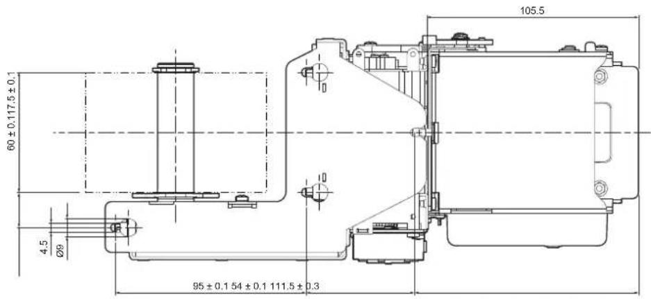
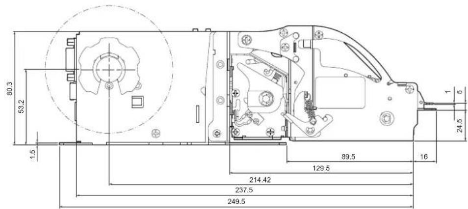
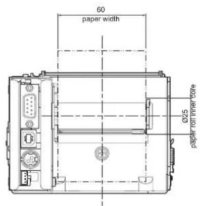
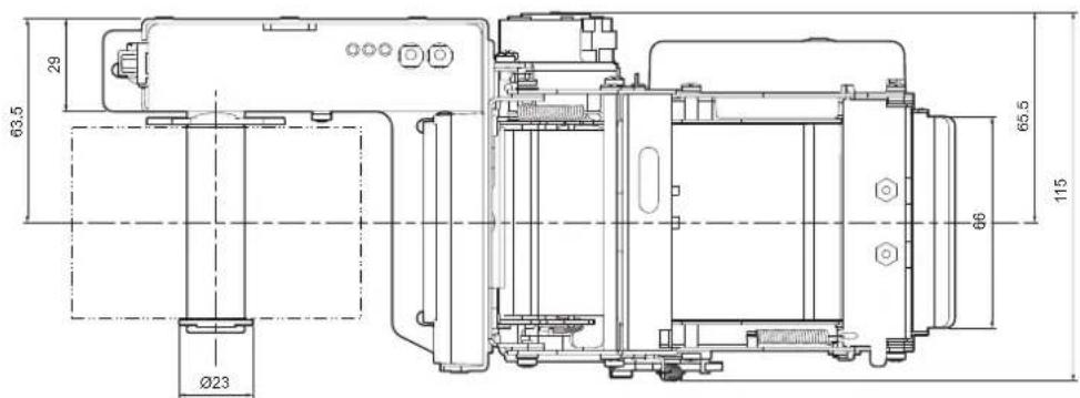
TPTCM60IIIIL
Length 188.4 mm
Height 195.3 mm
Width 112.4 mm
Weight 1150 g
All the dimensions shown in following figure are in millimetres.
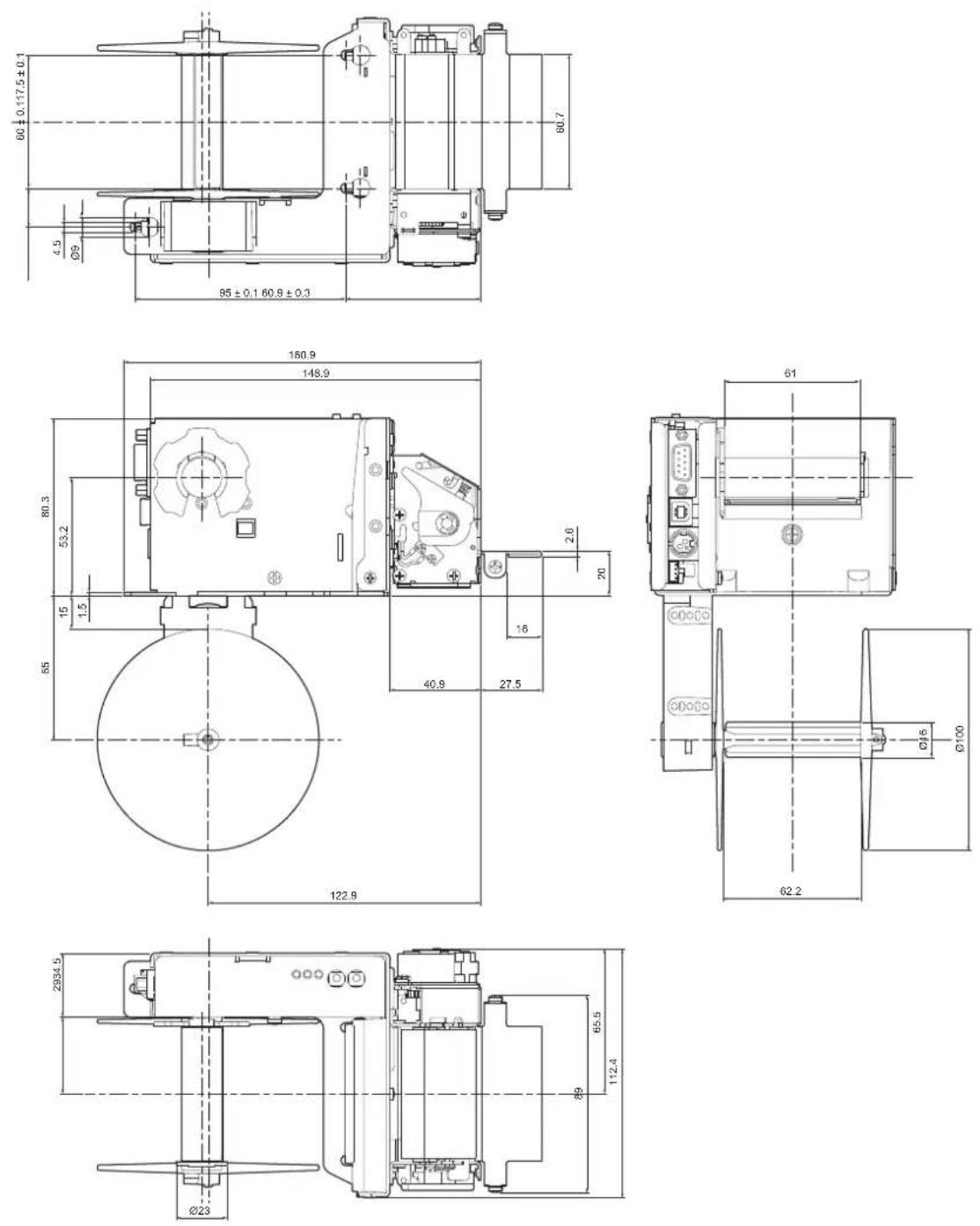
Length 227.4 mm
Height
(with autocutter down) 95.3 mm
(with autocutter up) 136.6 mm
Width 171.55 mm
Weight 1700 g
All the dimensions shown in following figure are in millimetres.
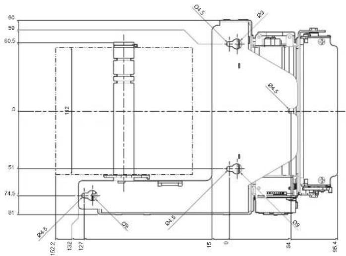
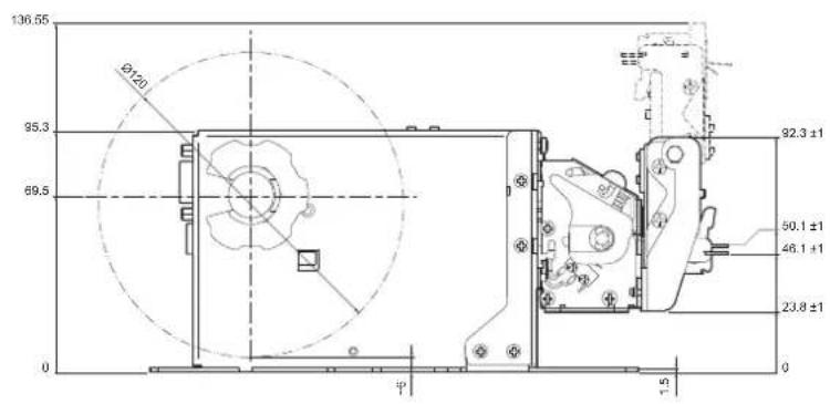
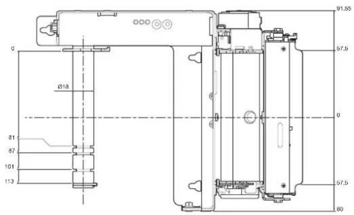
Length 227.4 mm
Height
(with autocutter down) 95.3 mm
(with autocutter up) 138.6 mm
Width 171.55 mm
Weight 1700 g
All the dimensions shown in following figure are in millimetres.
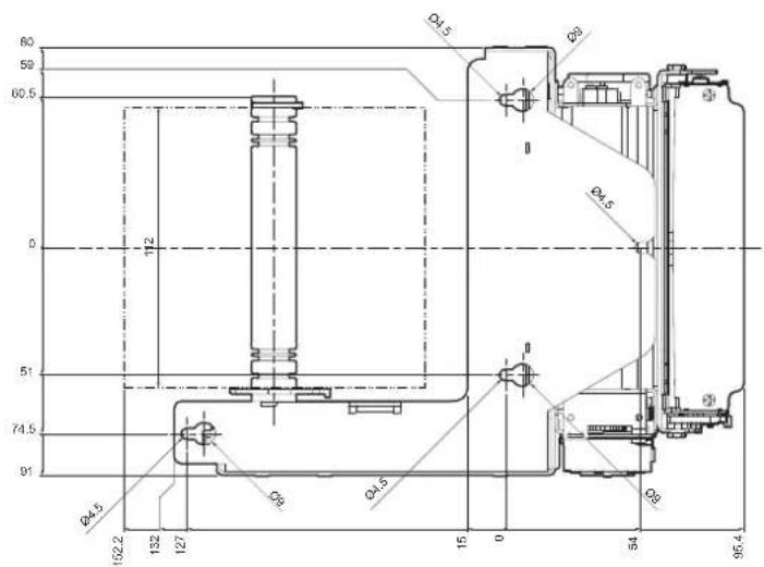
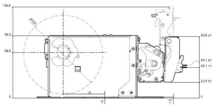
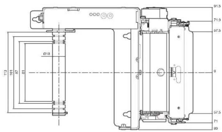
Length 300 mm
Height
(with ejector down) 95.3 mm
(with ejector up) 223.1 mm
Width 171.55 mm
Weight 2100 g
All the dimensions shown in following figure are in millimetres.
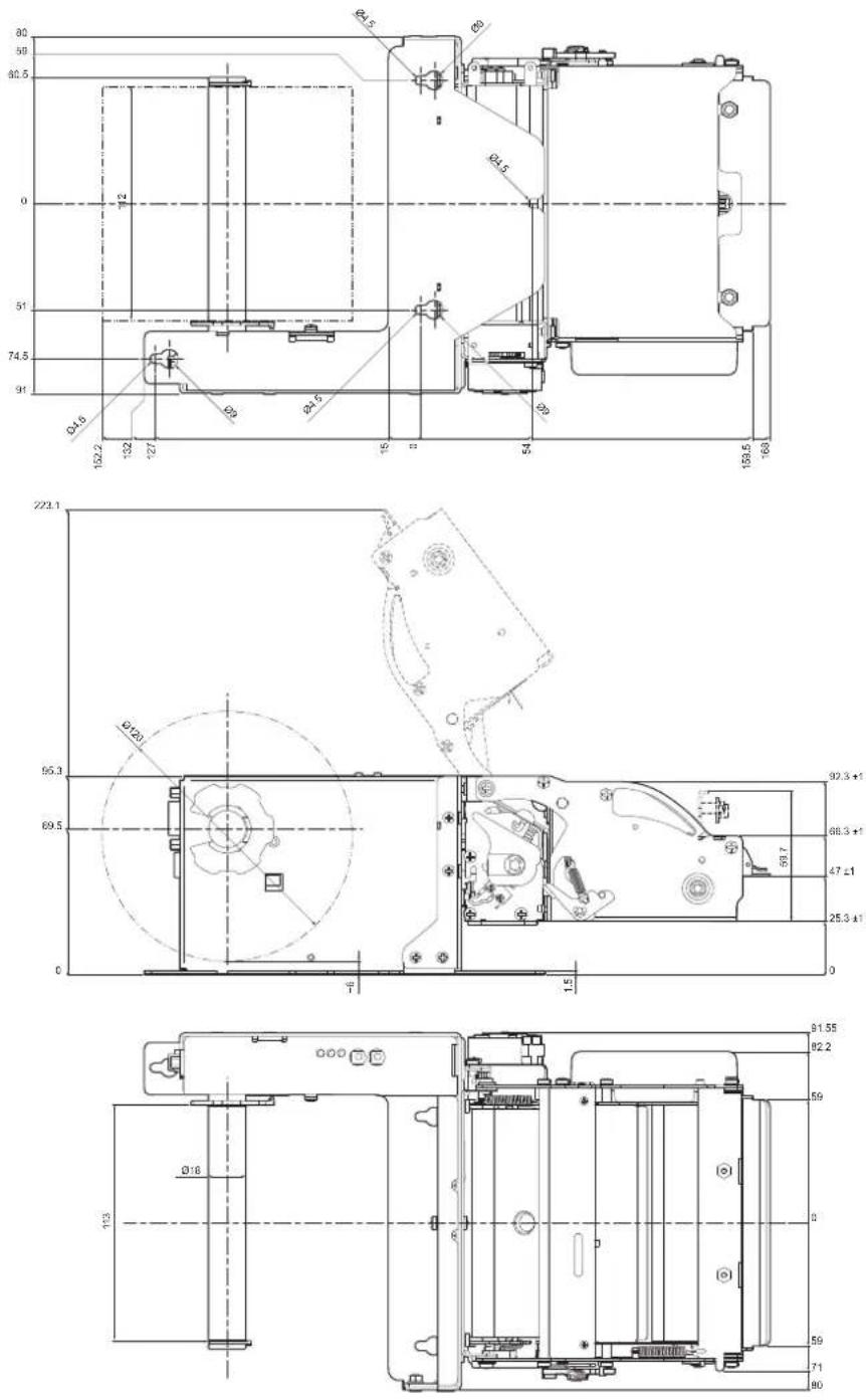
Length 227.4 mm
Height
(with autocutter down) 95.3 mm
(with autocutter up) 136.6 mm
Width 171.55 mm
Weight 1700 g
All the dimensions shown in following figure are in millimetres.
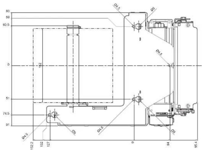
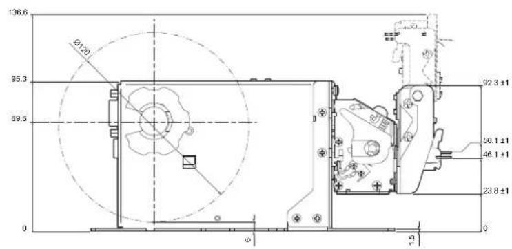
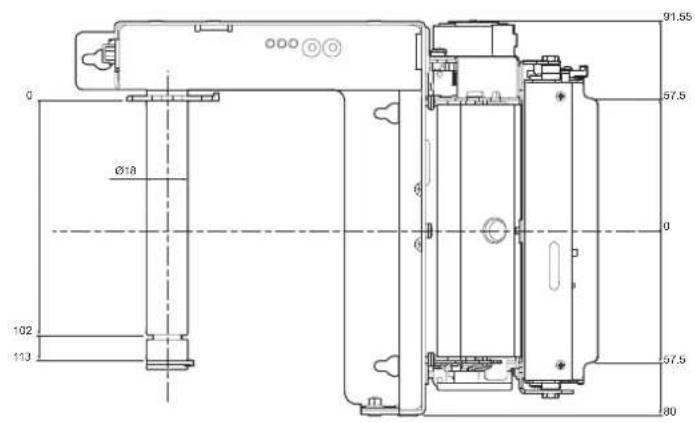
9.4 Device dimensions with paper roll holder code 974EX010000316 (optional)
TPTCM60III EJC
| Length | max. 352.5 mmmax. 397.5 mm (with paper roll ∅ max.160 mm) |
| Height | max. 183.7 mmmax. 228.7 mm (with paper roll ∅ max.160 mm) |
Width 115 mm
All the dimensions shown in following figure are in millimetres.
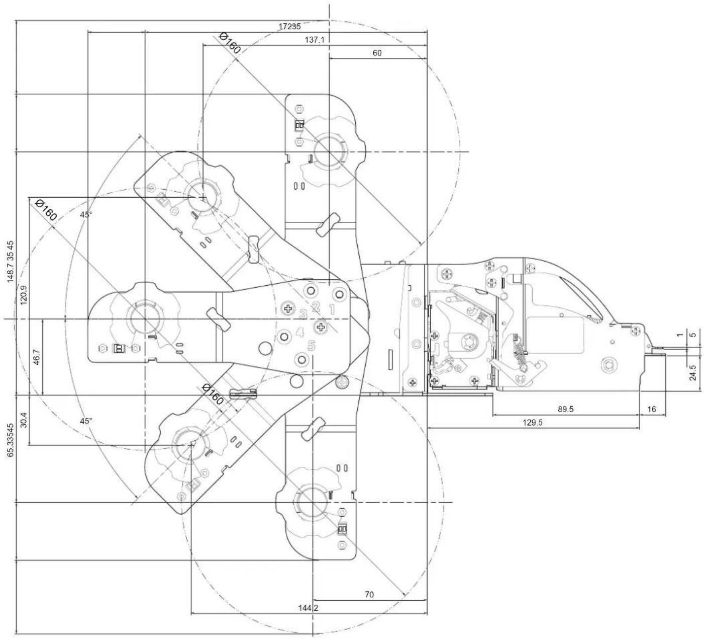
TPTCM60IIIIL
Length max. 275.4 mm
Height max. 298.7 mm
Width 112.4 mm
All the dimensions shown in following figure are in millimetres.
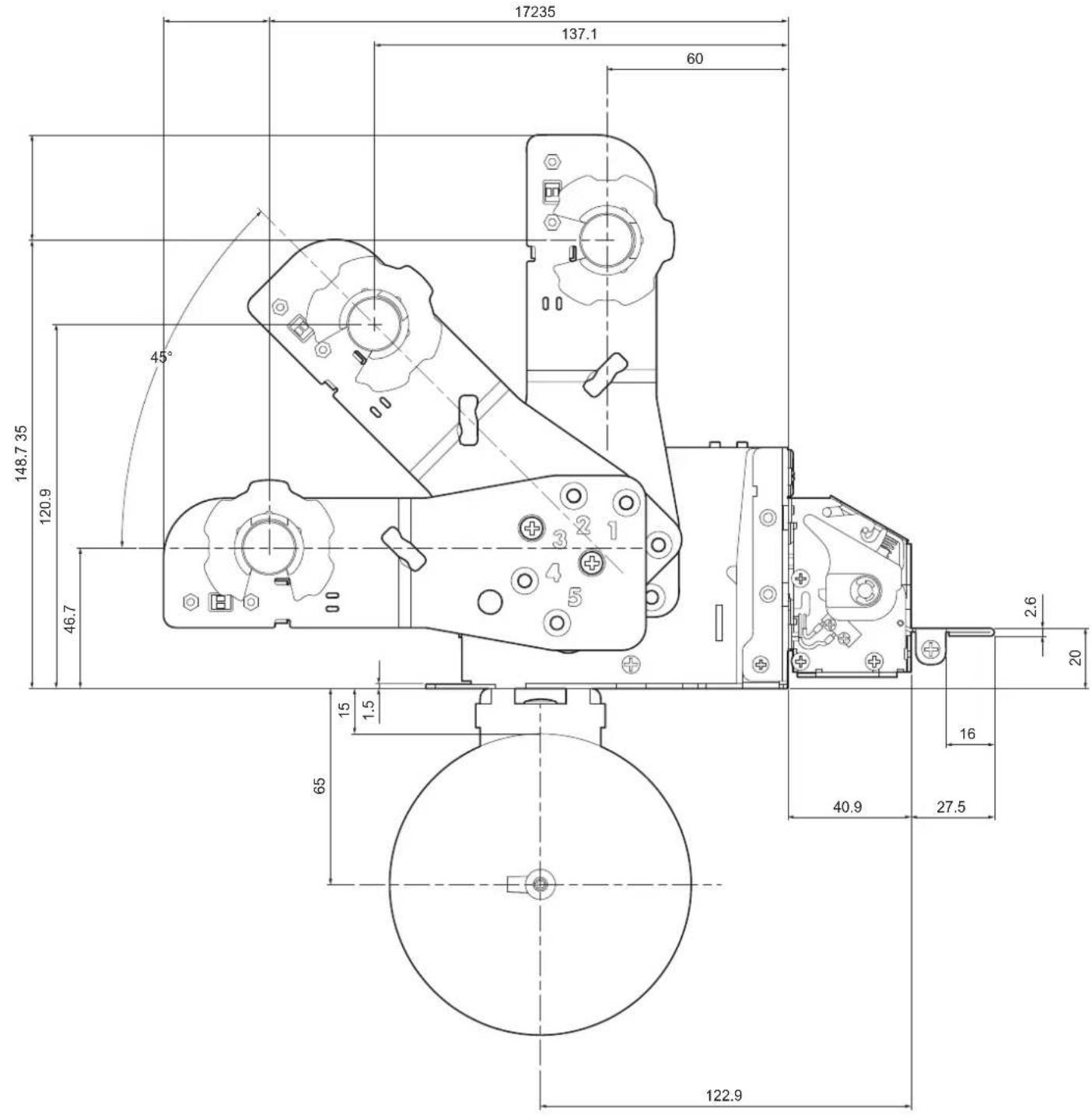
9.5 Device dimensions with paper roll holder code 974EU010000315 (optional)
TPTCM112III, TPTCM112III 300 DPI, TPTCM112III STRONG CUT, TPTCM112IIIIL, TPTCM112III CL
Length
max. 325.4 mm
max. 370.4 mm (with paper roll ∅ max.160 mm)
Height
max. 223.4 mm
max. 268.4 mm (with paper roll ∅ max.160 mm)
Width 115 mm
All the dimensions shown in following figure are in millimetres.
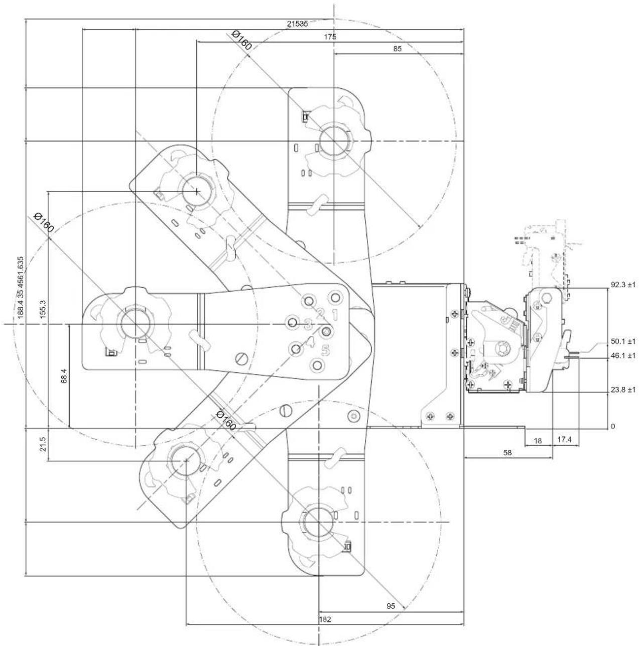
Length
max. 398 mm
max. 443 mm (with paper roll ∅ max.160 mm)
Height
max. 223.4 mm
max. 268.4 mm (with paper roll ∅ max.160 mm)
Width 115 mm
All the dimensions shown in following figure are in millimetres.
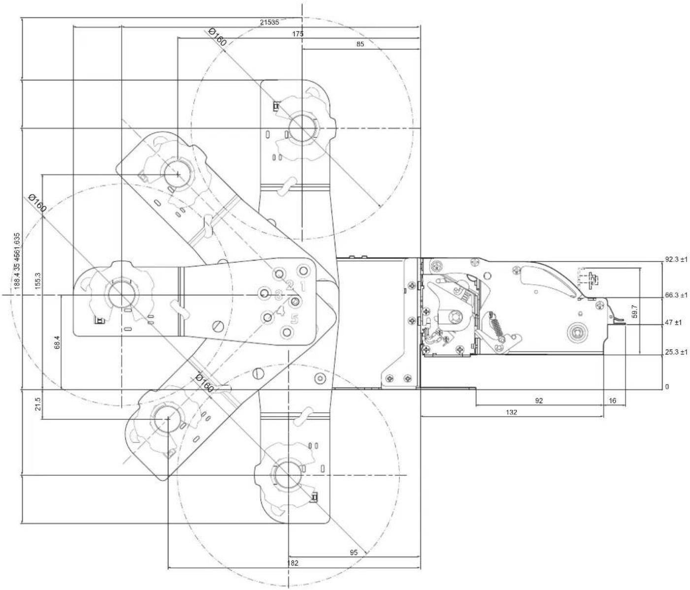
9.6 Power supply and power cord dimensions
The following table shows the dimensions of the power supply, the power cord and the adapter for power supply optionals for the device.
POWER CORD code 26100000000311 (optional for TPTCM60III EJC and TPTCM60IIIL)
Length 2000 mm
POWER SUPPLY code 963GE020000071 (optional for TPTCM60III EJC and TPTCM60IIIIL)
Length 130 mm
Height 36 mm
Width 57 mm
POWER SUPPLY code 963GE020000106 (optional for TPTCM112III, TPTCM112III 300 DPI, TPTCM112III STRONG CUT, TPTCM112III EJC, TPTCM112III EJC 300 DPI, TPTCM112IIIIL, TPTCM112III CL)
Length 146.2 mm
Height 39 mm
Width 75.2 mm
All the dimensions shown in following figures are in millimetres.
POWER CORD code 26100000000311
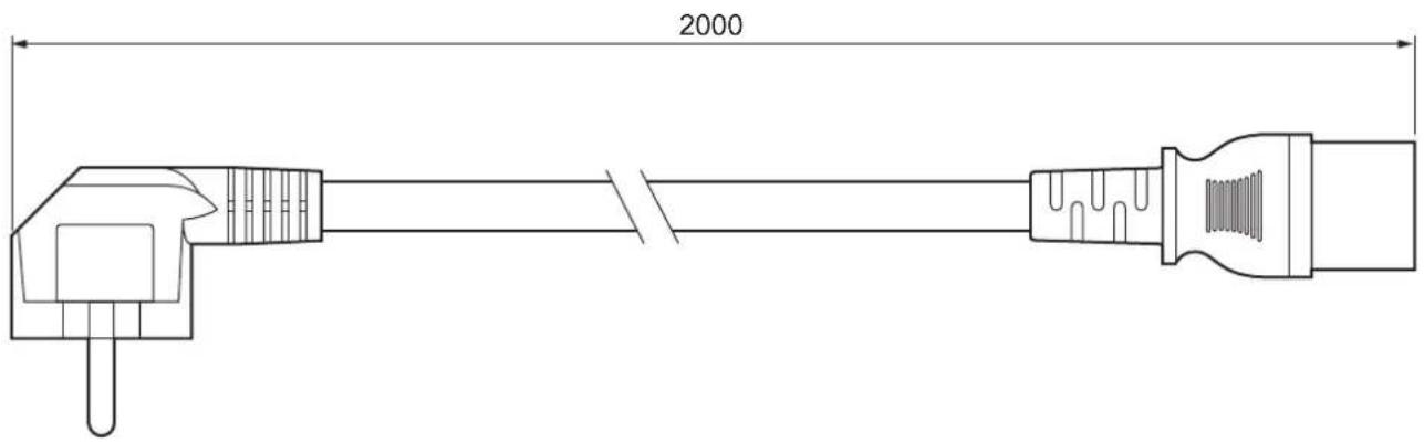

POWER SUPPLY code 963GE020000106
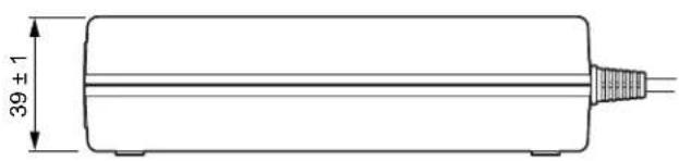
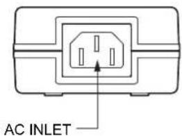
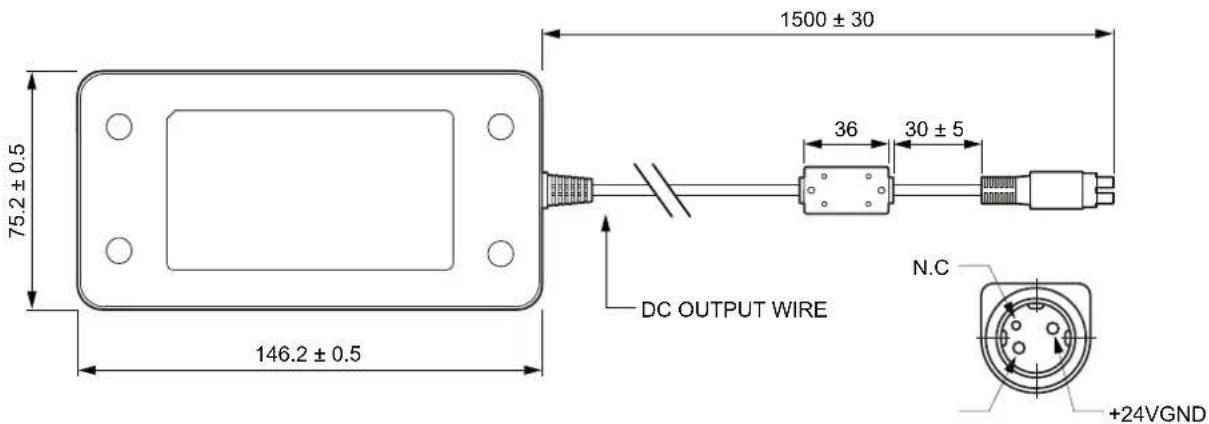
9.7 Paper specification
TPTCM60IIIL, TPTCM112IIIL
To properly use the alignment commands, you need to use paper with labels that comply with the dimensions shown in the following figure that apply to all paper widths handled by the devices.
All the dimensions shown in following figures are in millimetres.
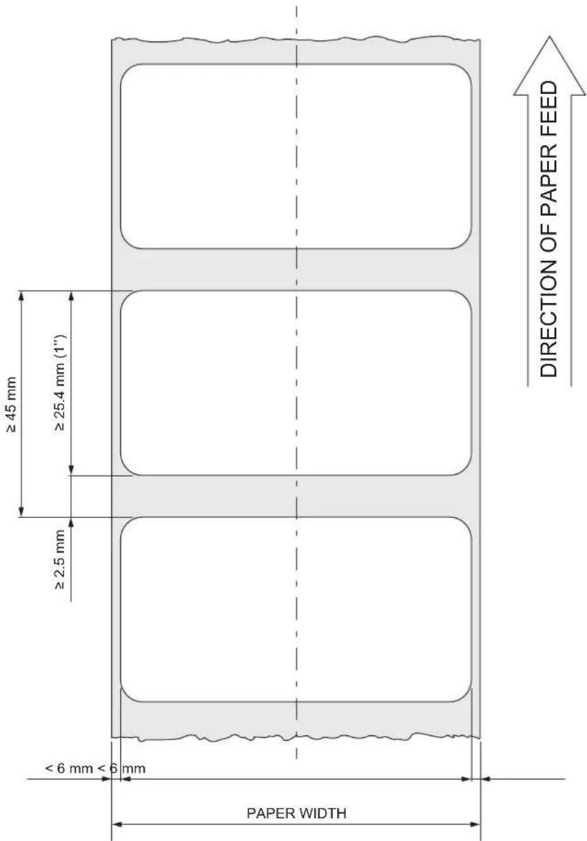
TPTCM112III, TPTCM112III 300 DPI, TPTCM112III STRONG CUT, TPTCM112III CL
The following image shows the placement of the black mark on paper. The notch must be printed on the non-thermal side of paper according to the dimensions shown in the following figure that apply to all paper widths handled by the device.
For devices with the alignment sensor in position C (see chapter 7), the paper specifications are symmetric to the axis of the paper.
All the dimensions shown in following figures are in millimetres.
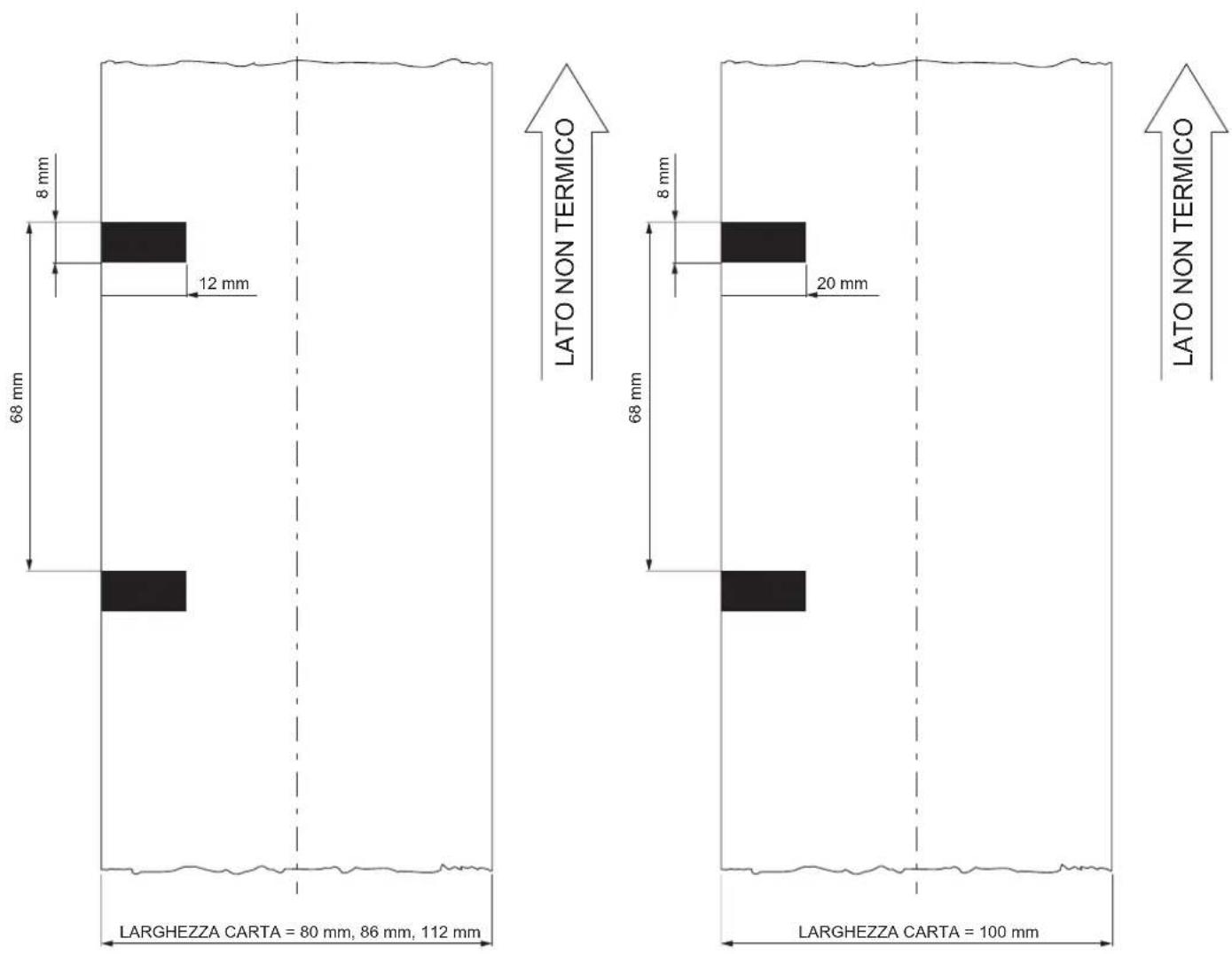
9.8 Character sets
The device has 3 fonts of varying width (11, 15 and 20 cpi) which may be related one of the coding tables provided on the device.
To know the coding tables actually present on the device, you need to print the font test (see paragraph 3.4).
You can set font and coding table by using the commands (see the commands manual of the device) or using the "Code Table", "Chars / Inch" and "Font Type" parameters during the setup procedure (see paragraph 6.6).
The following is the full list of coding tables that can be installed on the device.
| Coding table | |
| 0 PC437 - U.S.A., Standard Europe | |
| 1 Katakana | |
| 2 PC850 - Multilingual | |
| 3 PC860 - Portuguese | |
| 4 PC863 - Canadian/French | |
| 5 PC865 - Nordic | |
| 6 VISCII - Vietnamese Standard Code on request | |
| 11 PC851 - Greek on request | |
| 12 PC853 - Turkish on request | |
| 13 PC857 - Turkish on request | |
| 14 PC737 - Greek on request | |
| 15 ISO8859-7 - Greek on request | |
| 16 WPC1252 - Scandinavian | |
| 17 PC866 - Cyrillic 2 | |
| 18 PC852 - Latin 2 on request | |
| 19 PC858 per simbolo Euro in posizione 0xD5 | |
| 20 KU42 - Thai on request | |
| 21 TIS11 - Thai on request | |
| 26 TIS18 - Thai on request | |
| 30 TCVN_3 - Vietnamese on request | |
| 31 TCVN_3 - Vietnamese on request | |
| 32 PC720 - Arabic on request | |
| 33 WPC775 - Baltic Rim on request | |
| 34 PC855 - Cyrillic on request | |
| 35 PC861 - Icelandic on request | |
| 36 PC862 - Hebrew | |
| 37 PC864 - Arabic | |
| 38 PC869 - Greek on request | |
| 39 ISO8859-2 - Latin 2 on request | |
| 40 ISO8859-15 - Latin 9 on request | |
| 41 PC1098 - Farsi on request | |
| 42 PC1118 - Lithuanian on request | |
| 43 PC1119 - Lithuanian on request | |
| 44 PC1125 - Ukrainian on request | |
| 45 WPC1250 - Latin 2 | |
| 46 WPC1251 - Cyrillic | |
| 47 WPC1253 - Greek | |
| 48 WPC1254 - Turkish | |
| 49 WPC1255 - Hebrew | |
| 50 WPC1256 - Arabic | |
| 51 WPC1257 - Baltic Rim | |
| 52 WPC1258 - Vietnamese | |
| 53 KZ1048 - Kazakh on request | |
| 255 Space page | |
10 CONSUMABLES
The following table shows the list of available consumables for devices:
natural_image
Simple line drawing of a rolled document or scroll with a speaker icon (no text or symbols)67300000000352
THERMAL PAPER ROLL
weight = 70 g/m²
width = 60 mm
∅ external = 130 mm
∅ core = 25 mm
natural_image
Simple line drawing of a rolled document with a speaker icon (no text or symbols)TPTCM112III, TPTCM112III 300 DPI, TPTCM112III STRONG CUT, TPTCM112III EJC, TPTCM112III EJC 300 DPI, TPTCM112IIIIL, TPTCM112III CL
67300000000318
THERMAL PAPER ROLL
weight = 70 g/m²
width = 112 mm
∅ external = 95 mm
∅ core = 12 mm
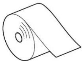
natural_image
Simple line drawing of a rolled document with sound waves (no text or symbols)11 ACCESSORIES
The following tables shows the list of available accessories for device.
(for technical specifications, see paragraph 9.1)
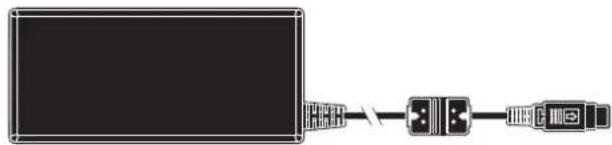
natural_image
Pure electrical circuit lines without any symbols26100000000311
POWER CORD SCHUKO PLUG
length = 2 m
(see paragraph 9.6)
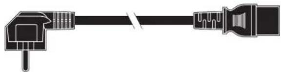
natural_image
Pure electrical connector diagram without any text or symbols26600000000012
ADAPTER CABLE
3 pin male power-DIN connector
length = 50 cm

26300000000603
LOW PAPER SENSOR BOARD
with cable length = 200 mm
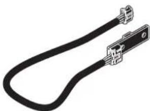
natural_image
Pure electrical connector diagram without any text or symbols974EX010000316
with low paper sensor board and cable for rolls with 160 mm external diameter
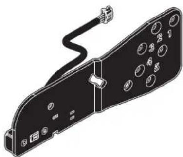
natural_image
Technical line drawing of a device panel with buttons and connectors (no text or symbols)21100000001349
TIE FOR ROLL LOCKING
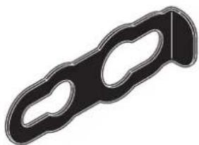
natural_image
Black and white illustration of a mechanical clamp or bracket (no text or symbols)21400000000948
PLASTIC BEZEL
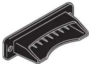
natural_image
Isometric line drawing of a mechanical component with slots and a bracket (no text or symbols)TPTCM112III, TPTCM112III 300 DPI, TPTCM112III STRONG CUT, TPTCM112III EJC, TPTCM112III EJC 300 DPI, TPTCM112IIIIL, TPTCM112III CL
963GE020000106
POWER SUPPLY
(for technical specifications, see paragraph 9.1)
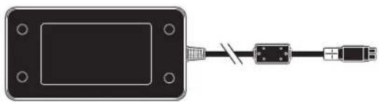
natural_image
Diagram of a device with a connector and cable, no text or symbols present26600000000012
ADAPTER CABLE
3 pin male power-DIN connector length = 50 cm

26300000000603
LOW PAPER SENSOR BOARD with cable length = 200 mm
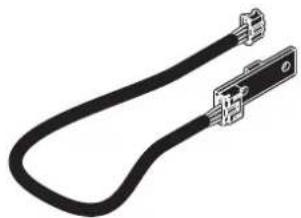
natural_image
Pure electrical connector diagram without any text, numbers, or symbols974EU010000315
ADJUSTABLE PAPER ROLL HOLDER with low paper sensor board and cable for rolls with 160 mm external diameter
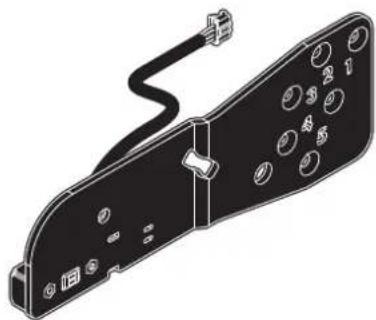
natural_image
Technical line drawing of a mechanical component with circular holes and a cable (no text or symbols)21100000001349
TIE FOR ROLL LOCKING
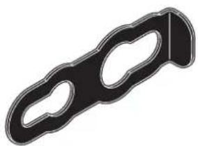
natural_image
Black and white illustration of a mechanical clamp or bracket (no text or symbols)21400000000947
PLASTIC BEZEL
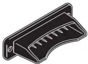
natural_image
Technical line drawing of a mechanical component with slots and a curved base (no text or symbols)12 TECHNICAL SERVICE
In case of failure, contact the technical service accessing the website www.custom4u.it and using the support tools on the homepage. It is advisable to keep the identification data of the product at hand.
The product code, the serial number and the hardware release number can be found on the product label (see paragraph 3.3). The firmware release number (SCODE) can be found:
• on the setup report (see paragraph 6.1)
- connecting the device to a PC and starting the "PrinterSet" tool (see paragraph 6.2)
- by consulting the "setup.ini" file (see paragraph 6.3)
CUSTOM®
CUSTOM S.p.A.
World Headquarters
Via Berettine, 2/B - 43010 Fontevivo, Parma ITALY
Tel. +39 0521 680111 - Fax +39 0521 610701
- Customer Service Department: www.custom4u.it
- THE IMAGES USED IN THIS MANUAL ARE USED AS AN ILLUSTRATIVE EXAMPLES. THEY COULDN'T REPRODUCE THE DESCRIBED MODEL FAITHFULLY.
- UNLESS OTHERWISE SPECIFIED, THE INFORMATION GIVEN IN THIS MANUAL
- ARE REFERRED TO ALL MODELS IN PRODUCTION AT THE ISSUE DATE OF THIS DOCUMENT.
- GENERAL INSTRUCTIONS
- GENERAL SAFETY INFORMATION
- THE CE MARK AFFIXED TO THE PRODUCT CERTIFY THAT THE PRODUCT SATISFIES THE BASIC SAFETY REQUIREMENTS.
- GUIDELINES FOR THE DISPOSAL OF THE PRODUCT
- TABLE OF CONTENTS
- ALIGNMENT 81
- MAINTENANCE 103
- SPECIFICATION 117
- CONSUMABLES....141
- ACCESSORIES 143
- TECHNICAL SERVICE....147
- INTRODUCTION
- IDENTIFICATION OF THE MODELS
- NOMENCLATURE DESCRIPTION
- DESCRIPTION
- Box contents
- TPTCM60III EJC
- TPTCM60IIIIL
- TPTCM112III, TPTCM112III 300 DPI
- TPTCM112III STRONG CUT, TPTCM112III CL
- TPTCM112III EJC, TPTCM112III EJC 300 DPI
- TPTCM112IIIL
- Device components: external views
- TPTCM112III, TPTCM112III 300 DPI, TPTCM112III CL
- TPTCM112III STRONG CUT
- Product label
- Key functions: power up
- Key functions: standby
- Status messages
- POWER ON LED
- INSTALLATION
- Fastening
- TPTCM112III, TPTCM112III EJC, TPTCM112III STRONG CUT, TPTCM112IIIIL, TPTCM112III CL
- Connections
- Pinout
- POWER SUPPLY
- USB INTERFACE
- RS232 SERIAL INTERFACE
- LOW PAPER
- Driver and SDK
- OPERATION
- Adjusting paper width
- TPTCM112III, TPTCM112III 300 DPI, TPTCM112III EJC, TPTCM112III EJC 300 DPI, TPTCM112III
- Switch the device on
- Loading the paper roll
- Fixing the paper on rewinder
- Issuing ticket
- CONFIGURATION
- Configuration by keys
- Configuration by software
- Configuration by file
- 1
- Enter setup
- 2
- 3
- 4
- ATTENTION:
- Device status
- Communication parameters
- Operating parameters
- Alignment parameters
- Hexadecimal dump
- ALIGNMENT
- Enable alignment
- TPTCM112III, TPTCM112III STRONG CUT, TPTCM112III CL
- Calibration
- Labels gap detection sensor autoset procedure
- TPTCM112III
- Printing area
- TPTCM60IIIIL, TPTCM112IIIIL
- MAINTENANCE
- Paper jam
- Planning of cleaning operations
- EVERY PAPER CHANGE
- EVERY 5 PAPER CHANGES
- AS NEEDED
- NOTES:
- Cleaning
- Platen roller
- Sensor for paper presence in input
- Autocutter (TPTCM60III EJC, TPTCM112III EJC)
- Case
- Firmware upgrade
- SPECIFICATION
- Hardware specifications
- PRINTER
- Resolution
- Printing method Thermal, fixed head
- Head life (1)
- Printing width 80 mm
- Printing method Normal, 90°, 180°, 270°
- Printing format Height/Width from 1 to 8, bold, reverse, underlined, italic
- Character font
- Printable barcodes
- Printing speed (1)(3)
- PAPER
- DEVICES ELECTRICAL SPECIFICATIONS
- ENVIRONMENTAL CONDITIONS
- Character specifications
- Device dimensions with paper roll holder code 974EX010000316 (optional)
- Device dimensions with paper roll holder code 974EU010000315 (optional)
- Power supply and power cord dimensions
- Paper specification
- TPTCM60IIIL, TPTCM112IIIL
- TPTCM112III, TPTCM112III 300 DPI, TPTCM112III STRONG CUT, TPTCM112III CL
- Character sets
- CONSUMABLES
- ACCESSORIES
- 963GE020000106
- 26600000000012
- 26300000000603
- 974EU010000315
- 21100000001349
- 21400000000947
- TECHNICAL SERVICE
- CUSTOM®
Brand : CUSTOM
Model : TPTCM112III
Category : Printer