MI-394 - Flat Screen Mount Mount-It! - Free user manual and instructions
Find the device manual for free MI-394 Mount-It! in PDF.


| Product Type | Full Motion TV Wall Mount with Long Extension Dual Arms |
| Brand | Mount-It! |
| Model | MI-394 |
| TV Size Compatibility | 65" to 110" |
| VESA Patterns Supported | 100x100, 200x200, 300x300, 400x200, 400x400, 600x400, 800x600 mm |
| Weight Capacity | 275 lbs (125 kg) |
| Maximum Extension from Wall | 23.7" (602 mm) |
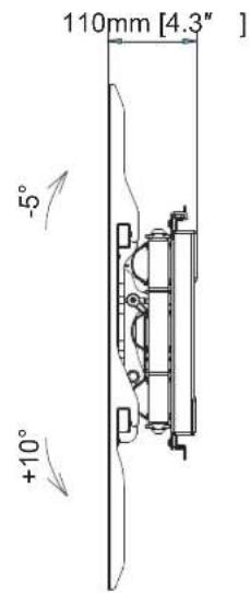
| Minimum Depth (Retracted) | 4.3" (110 mm) |
| Lateral Slide Range | Up to 15.7" (400 mm) |
| Tilt Range | -5° to +10° |
| Leveling Adjustment | ±5° (post-installation) |
| Cable Management | Integrated clips on arms |
| Material | Steel |
| Color | Black |
| Installation Types | Wood stud (16" or 24" spacing) or concrete/brick |
| Package Contents | Main mount body, 2 TV brackets, hardware kit (screws, washers, anchors), 4 safety brackets (AA), wall plate template, wrench |
| Safety Features | Safety brackets to prevent lift-off, locking bars for slide limit |
| Warranty | Visit mount-it.com for registration and warranty details |
| Tools Required | Stud finder, bubble level, drill, drill bits (7/32" for wood, 3/8" for concrete), socket wrench (included) |
Frequently Asked Questions - MI-394 Mount-It!
User questions about MI-394 Mount-It!
0 question about this device. Answer the ones you know or ask your own.
Ask a new question about this device
Download the instructions for your Flat Screen Mount in PDF format for free! Find your manual MI-394 - Mount-It! and take your electronic device back in hand. On this page are published all the documents necessary for the use of your device. MI-394 by Mount-It!.
USER MANUAL MI-394 Mount-It!
MI-394 INSTALLATION MANUAL
Full Motion TV Wall Mount With Long Extension Dual Arms
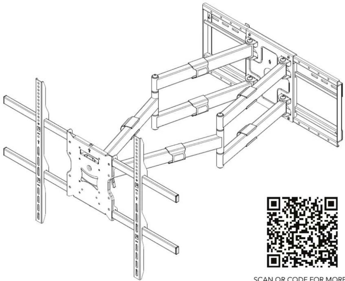
natural_image
Technical line drawing of a mechanical frame assembly with mounting brackets and structural supports, accompanied by a QR code for scanning (no text or symbols on the diagram itself)
SCAN QR CODE FOR MORE INFORMATION ON THIS ITEM.
VESA
100x100.200x200.300x300
400x200.400x400
600×400.800×600
MOST
65"-110"
TVs

125kg/275lbs
WARNING: This installation manual is intended to provide guidance on how to install the TV mount and the TV on a suitable wall. Please contact a qualified professional if you are unsure of the steps described in the manual or have doubts about the safety of the installation. Improper installation may cause damage or serious injury. We cannot be held liable for damage or injury caused by improper mounting, incorrect assembly, inappropriate use or for use cases not explicitly specified in this document.
CHOKING HAZARD. Package includes small parts.
Adult supervision is required. Not for
PACKAGE CONTENTS
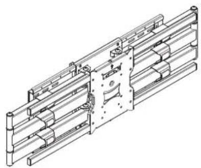
natural_image
Technical line drawing of a mechanical assembly with railings and mounting brackets (no text or symbols)Main Mount Body (X1)X1
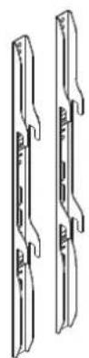
TV brackets ( )
TV Mounting Hardware Wall Mounting Hardware
A-

(M4x16)-4pcs
B-

(M5x16)-4pcs
C-

(M6x16)-4pcs
D-
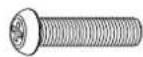
(M8x25)-4pcs
E-

(∅16x∅6.2x1.5)-4pcs
F-

(M5x8)-4pcs
G-
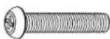
(M8x45)-4pcs
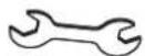
wrench-1pcs
H-
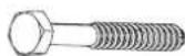
(8x65)-6pcs
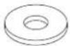
(∅16x∅8.2x1.5)-6pcs
1-
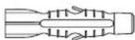
Plastic Anchor -6pcs
AA -
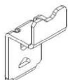
Safety Brackets -4pcs
BB -
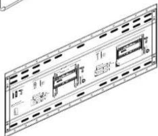
Wall Plate Template -1pcs
Check carefully to make sure there are no missing or defective parts. Some hardware provided may not be used. Use the correct wall mounting and TV mounting hardware suitable for your installation.

CAUTION: DO NOT INSTALL ON DRY WALL ALONE. INSTALL MOUNT ON WOOD STUDS. USER MUST VERIFY THE WALL CAN HOLD THE WEIGHT OF THE TV AND THE TV MOUNT.
1a. INSTALLATION OPTION 1: Wood Stud Installation (Suitable for 16" or 24" apart studs)
1). Use a stud finder to locate the dry wall studs and mark the desired installation locations with a pencil.
2). Attach the Wall Plate Template (BB) to the wall at the desired installation location.
3). Ensure the Wall Plate Template (BB) horizontal alignment is verified with a bubble level and mark 6 lag bolt installation locations on the stencil and the wall. Attempt to locate the lag bolt locations on the middle of the studs.
4). Use a 7/32" (5.5mm) drill bit to drill a pilot hole on the wall with a depth of at least 2.6" (65mm). Please note, failure to drill pilot holes may result in the lag bolt heads snapping during installation.
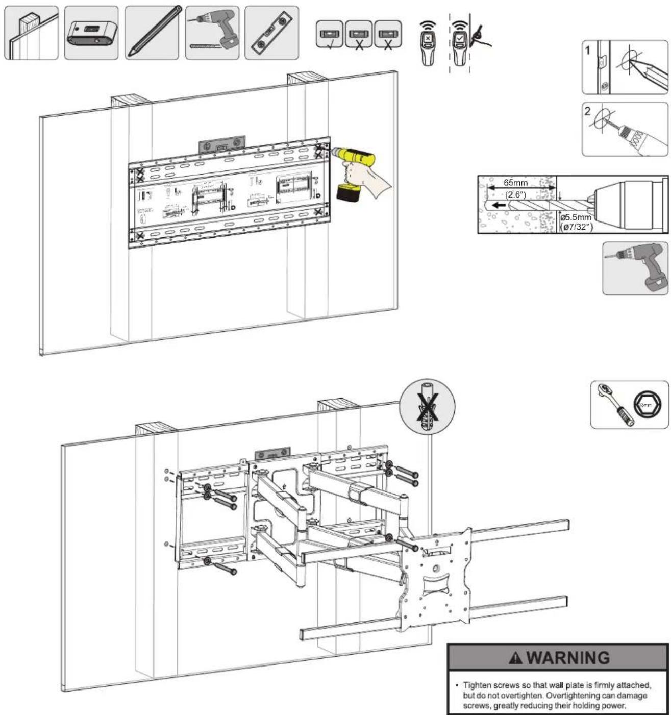
Secure the Wall Plate to the wall with 6 x Lag Bolts (H) and 6 x Washers (H). NOTE: Do not use Wall Anchor (I) for wood stud installation.
1b. INSTALLATION OPTION 2: Concrete/Brick Wall Installation
1). Attach the Wall Plate Template (BB) to the wall at the desired installation location.
2). Ensure the Wall Plate Template (BB) horizontal alignment is verified with a bubble level and mark 6 lag bolt installation locations on the stencil and the wall.
3). Use a 3/8" (10 mm) drill bit to drill a pilot hole on the wall with a depth of at least 2.6" (65mm). Please note, failure to drill pilot holes may result in the lag bolt heads snapping during installation.
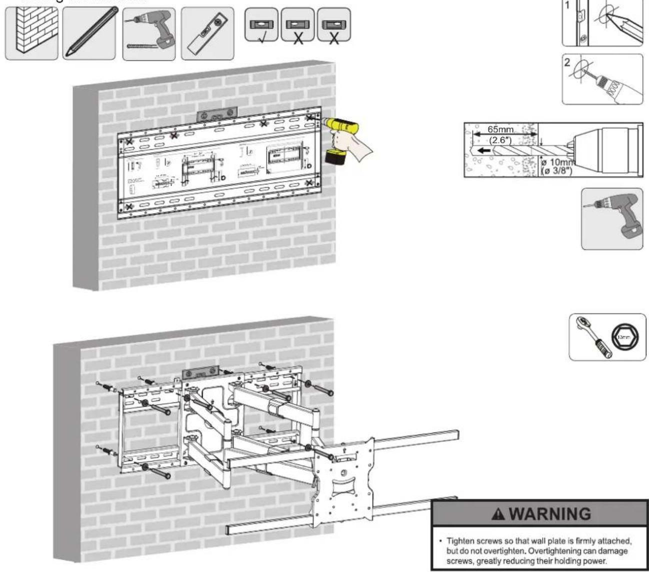
Insert 6 x Wall Anchors (I) into holes. Secure the Wall Plate to the wall with 6 x Lag Bolts (H) and 6 x Washers (H).
2.
This full motion TV wall mount comes with a sliding mechanism that allows the arms and the TV to slide horizontally left or right for up to 15.7 inches, while the wall plate is stationary on the wall. This feature allows the TV to be placed at an optimal position, regardless of the position of the wall studs. The mount will ship with the locking bars installed in place at their center position. If the sliding function will be used, take off the locking plates by removing the bolts that hold them in place. Place the top locking bar at the desired position to fix the left slide limit of the arms and place the bottom bar at the desired position to fix the right side limit of the arms. The raised metal piece at the end of the locking bars limit the slide of the arms. Ensure the locking bars are oriented correctly to ensure both the left and right side locking bars correctly limit the slide. Ensure both of the bolts are tightened at each locking bar's position to prevent the arms from sliding off the wall plate. WARNING: FAILURE TO INSTALL THE LOCKING BARS ADEQUATELY MAY RESULT IN THE ARMS AND THE TV FROM SLIDING OFF THE WALL PLATE.
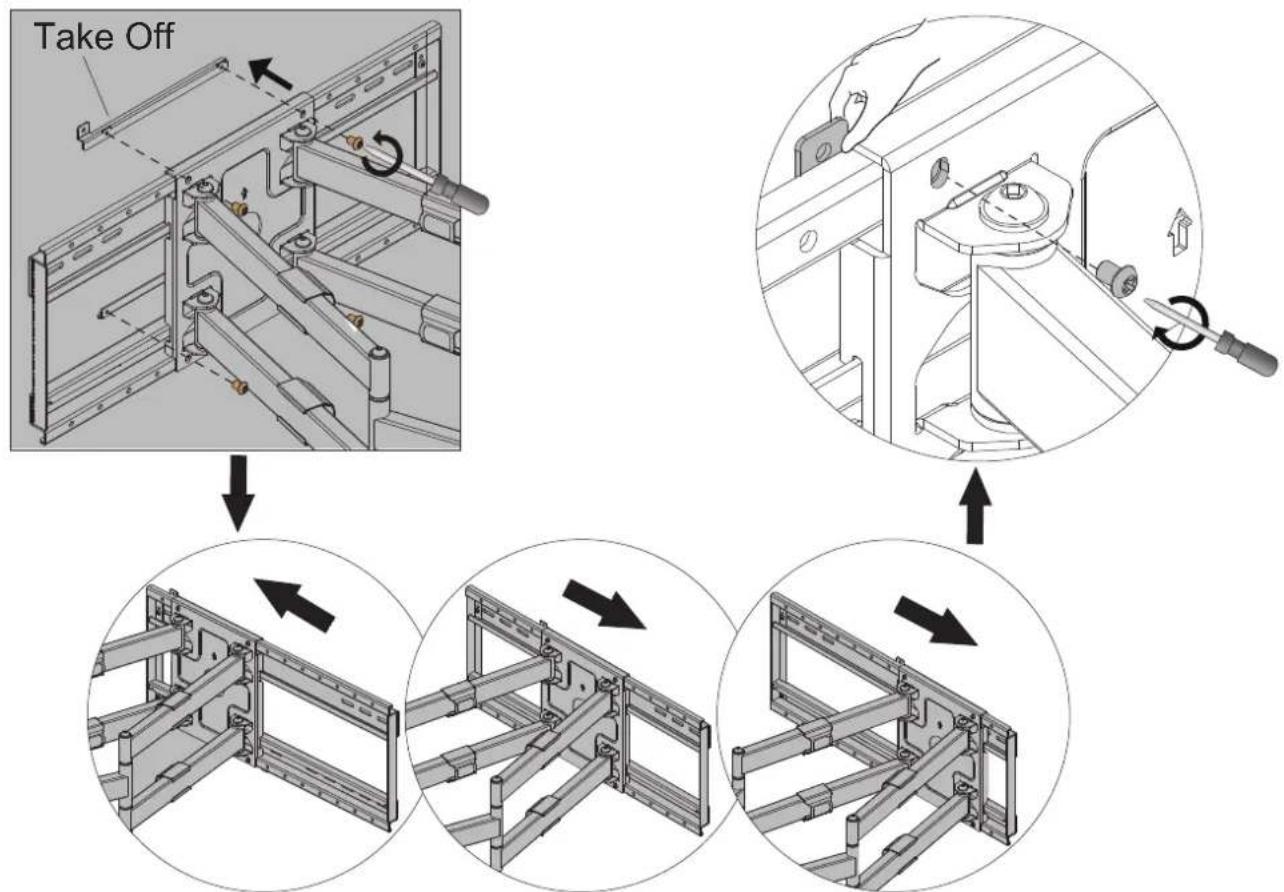
3a.
Attaching the TV to the Mount (For Displays With Smaller Bolt Hole Patterns) For TVs with smaller bolt hole patterns of VESA 100x100 , 100x200 , 200x100 and 200x200mm, the TV can be mounted directly on the plate, without the extension bars.
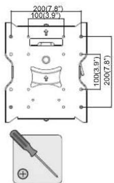
1.
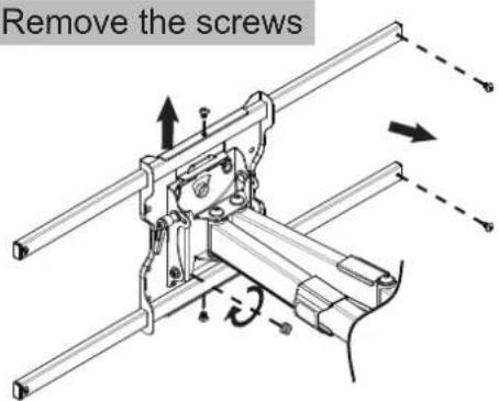
3.
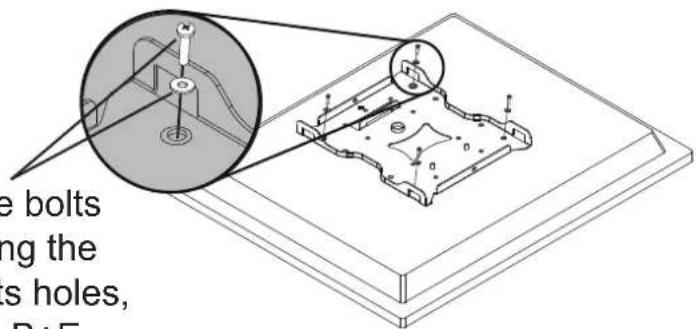
Attach VESA Plate to TV
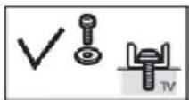
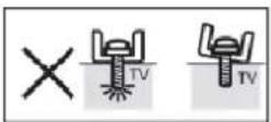
Use the bolts matching the TV bolts holes, A+E or B+E or C+E or D or G
2.
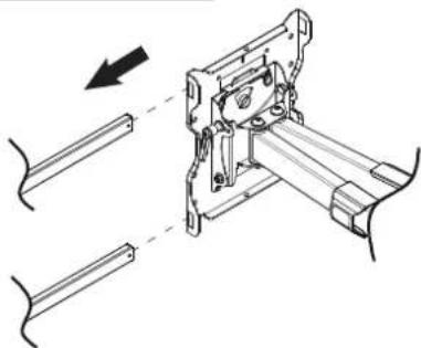
Take off the rails
natural_image
Mechanical assembly diagram showing a bracket with shafts and mounting components, no text or symbols present4.
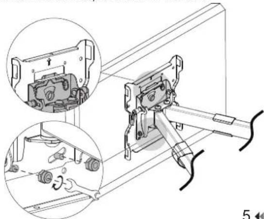
Attach VESA Plate to Arms
Slide in the VESA plate on to the notch on the arms, attach the two safety screws behind the VESA plate to lock in the VESA plate to the arms, as shown below.
natural_image
Mechanical assembly diagram showing a motor with internal components and a close-up of the component (no text or symbols visible)3b.
Attaching the TV to the Mount (For Displays With Larger Bolt Hole Patterns) For TVs with larger bolt hole patterns of VESA 300x300,400x200,400x400,600x400,800x600 mm, use the TV brackets and the extension bars to install the TV to the mount.
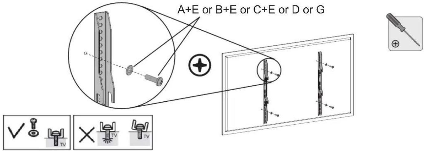
Attach the 2 x TV Brackets to the back of theTV by using screws A+E or B+E or C+E or D or G. NOTE: The hardware packet provided fits most TVs in the market. If your TV requires different hardware, please contact us at mount-it.com to procure additional hardware kits.
Ensure the screws are adequately engaged with the screw holes on the TV. Do not overtighten the screws. Ensure the TV brackets sit flat with the back of the TV. Do not overtighten the screws. Ensure the TV brackets sit flat with the back of the TV.
4. Hanging TV On The Wall Mount Arms
natural_image
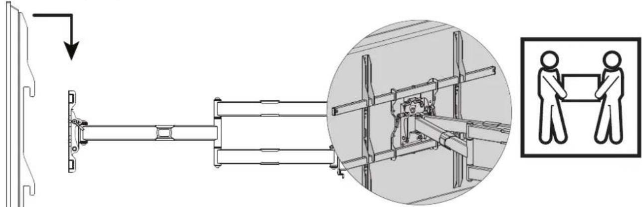
Technical diagram showing a mechanical assembly with an inset close-up of a structural frame and two human figures holding a tray (no text or symbols present)Lift the TV up (two persons recommended) and hang the TV brackets on to the wall mount extension bars.
5. Securing The TV On The Mount
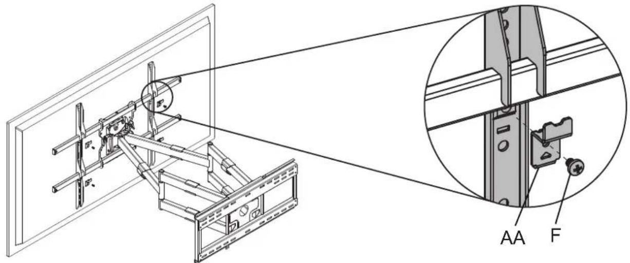
Secure the TV brackets on the mount by attaching the 4 x AA Safety Brackets with 4 x F Screws as shown on the image.
NOTE: Failure to secure the TV brackets to the mount with AA Safety Brackets may result in accidental lift off of the TV from the extension bars, possibly resulting in bodily or property damage.
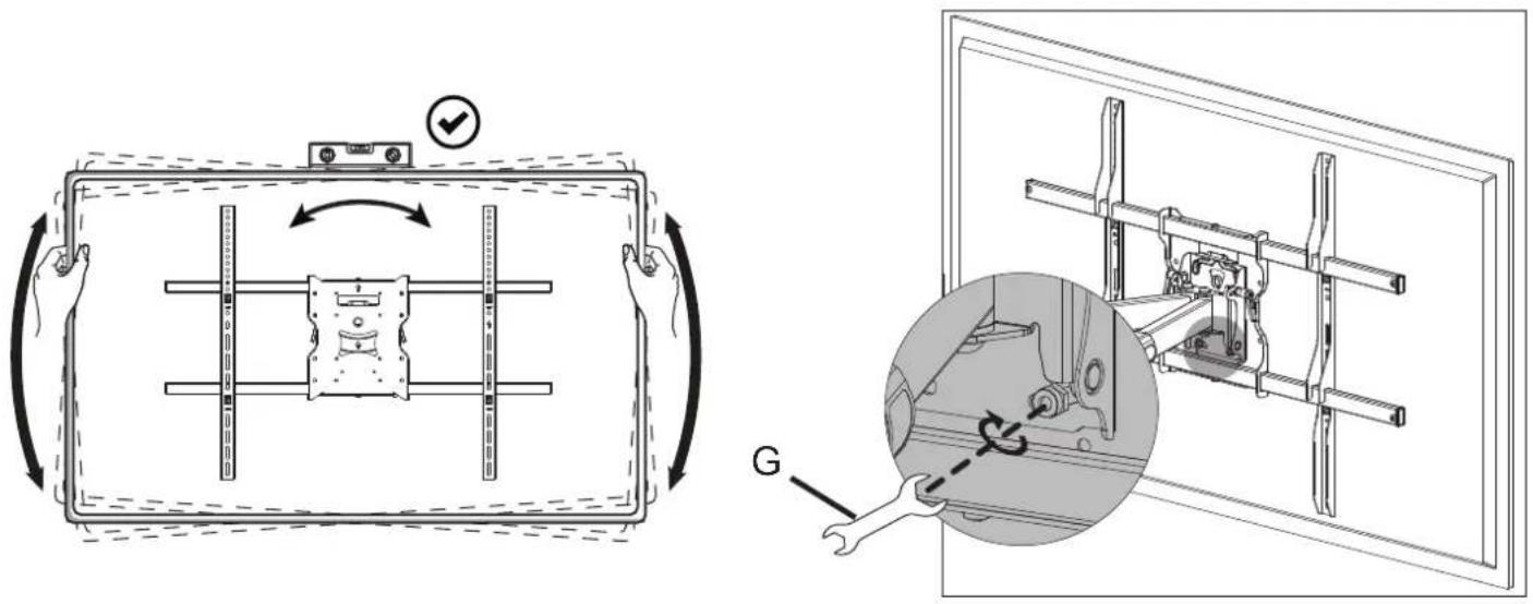
6. Leveling adjustment -5^-+5^
The mount allows up to 5 degrees of leveling adjustment post installation. To adjust the level of the TV, place a bubble level on top of the TV, loosen the 2 x G bolts located behind the VESA plate, level the TV and tighten the 2 x G bolts to lock the TV in position.
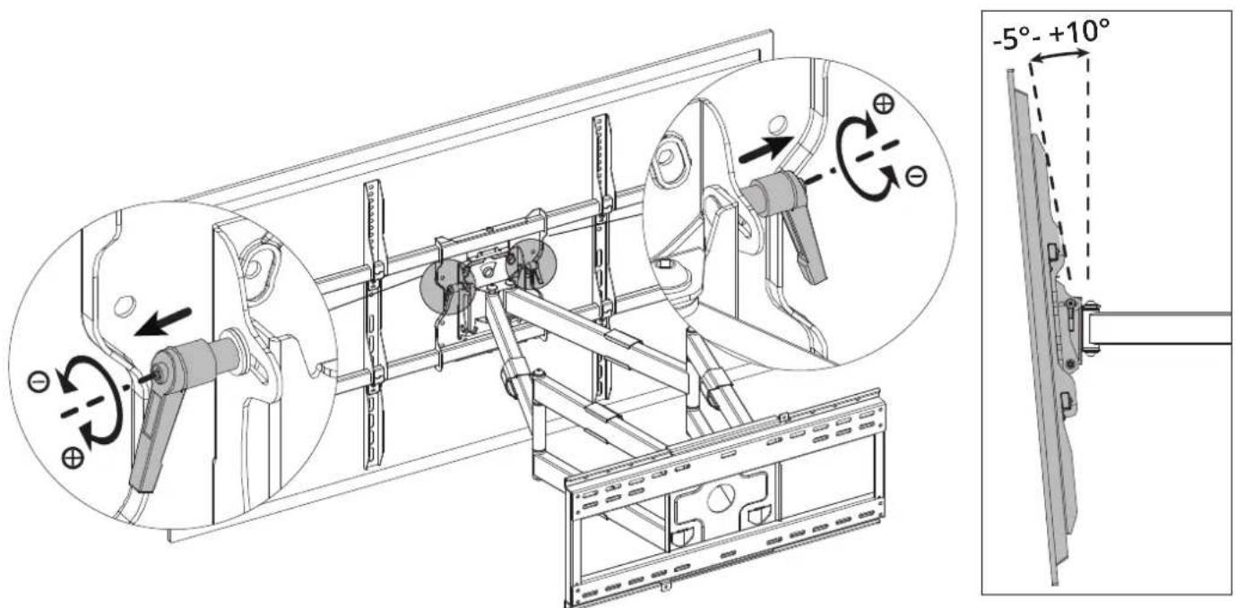
7. Tilt adjustment -5^ - +10^
The mount can tilt down up to 10 degrees and up 5 degrees. To adjust the tilt angle of the TV, pull out the tilt adjustment levers on both sides of the mount and turn counterclockwise to loosen the screws. Adjust the tilt to the desired angle and turn the tilt adjustment lever clockwise to tighten the screws. NOTE: IF THE TV TILTS DOWN AFTER A PERIOD OF USE, CHECK THE TILT ADJUSTMENT LEVER TIGHTNESS AND TIGHTEN IF NECESSARY.
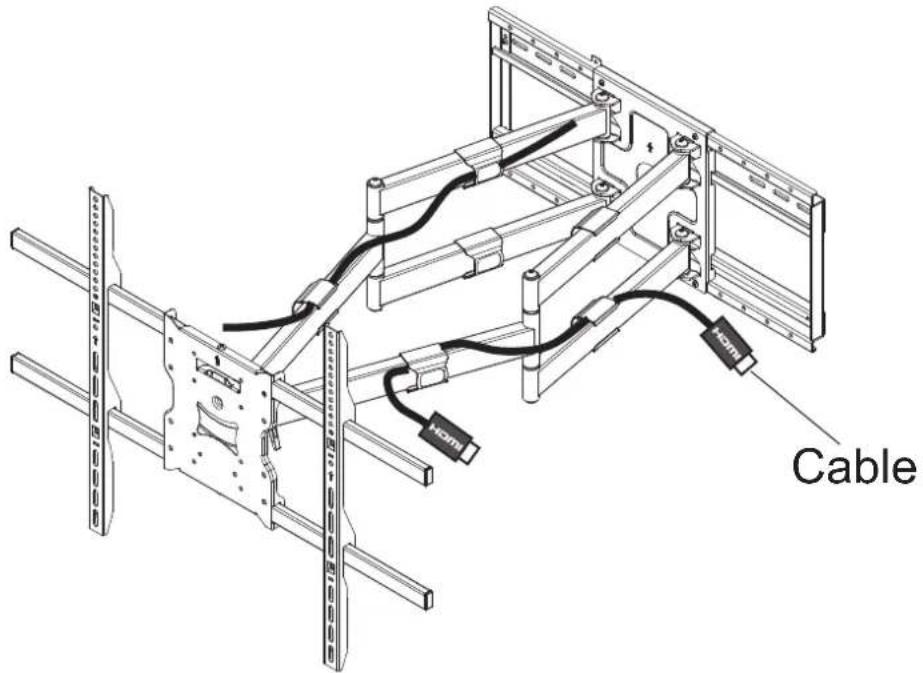
8.
Use the integrated cable management clips on the arms to route cables to the back or side of the TV.
Dimensions
![825mm [32.5" ]Max φ8.3mm [φ0.3" 200mm [7.9" 100mm [3.9" 3.9" ±5° 100mm 200mm [7.9" 602mm [23.7"](/content/2026/05/957416/images/a268986b8cf4e2299d13ddca982d24673f3392fd87332ecab874322659af14f7.jpg)
![980mm [38.6"]](/content/2026/05/957416/images/1e0e38fde94785a83a0fc7fea01b1580a17401ee6aaa0d20c50a9949be2b38db.jpg)
![690mm [27.2" ] 609.6mm [24.0" 406.4mm [16.0" 648mm [25.5" 139mm [5.5" 220.5mm [8.7" 292mm [11.5"](/content/2026/05/957416/images/d8d35a056ebcf860b2f5dc56a18783a8b1479943fdbc709e21c22cc9cbb7d3dc.jpg)
• VISIT US AT MOUNT-IT.COM FOR PRODUCT REGISTRATION AND WARRANTY INFORMATION.
- CONTACT US AT SUPPORT@MOUNT-IT. COM OR 855-925-5668 FOR QUESTIONS OR COMMENTS.
- MI-394 INSTALLATION MANUAL
- Full Motion TV Wall Mount With Long Extension Dual Arms
- CHOKING HAZARD. Package includes small parts.
- Adult supervision is required. Not for
- TV Mounting Hardware Wall Mounting Hardware
- 1a. INSTALLATION OPTION 1: Wood Stud Installation (Suitable for 16" or 24" apart studs)
- 1b. INSTALLATION OPTION 2: Concrete/Brick Wall Installation
- 2.
- 3a.
- 1.
- 3.
- 4.
- 3b.
- Hanging TV On The Wall Mount Arms
- Securing The TV On The Mount
- Leveling adjustment -5°-+5^°
- Tilt adjustment -5° - +10°
- 8.
Brand : Mount-It!
Model : MI-394
Category : Flat Screen Mount