
GCS1816 - KVM switch IOGEAR - Free user manual and instructions
Find the device manual for free GCS1816 IOGEAR in PDF.


| Product Type | 16-Port USB HDMI KVMP Switch |
| Model | GCS1816 |
| Brand | IOGEAR |
| Direct Computer Connections | 16 |
| Maximum Computers (via Cascade) | 256 (up to 2 levels) |
| Port Selection Methods | Front panel pushbuttons, hotkeys, On-Screen Display (OSD) |
| Video Resolution Support | 480i, 480p, 720p, 1080i, 1080p (1920 x 1200) with widescreen support |
| Power Consumption | DC 5.0V; 12.0W |
| Weight | 7.68 lbs (3.49 kg) |
| Dimensions (L x W x H) | 17" x 10.1" x 1.73" (43.72 cm x 25.66 cm x 4.4 cm) |
| Housing Material | Metal |
| Operating Temperature | 0°C – 50°C |
| Storage Temperature | -20°C – 60°C |
| Humidity | 0% – 80% RH, non-condensing |
| Console Ports | 1 x USB Type-A (keyboard), 1 x USB Type-A (mouse), 1 x HDMI (video), 2 x 3.5mm audio jacks (front and rear) |
| KVM Ports | 16 x USB Type-B, 16 x HDMI, 16 x 3.5mm audio jacks |
| USB 2.0 Hub | 2 x USB Type-A (1 front, 1 rear) |
| Audio Support | 2.1 channel surround sound, independent switching |
| Video DynaSync™ Technology | Yes - eliminates boot-up display problems and optimizes resolution |
| Firmware Upgrade | Via RJ-11 port and included cable |
| OSD Languages | English, German, Japanese, Traditional Chinese, Simplified Chinese, Spanish, French, Russian |
| Hotkey Support | Yes (Num Lock + - or Ctrl + F12) |
| Multi-Display Support | Up to 8 stacked units, each computer with multiple video cards |
| Included Cables | 2 x Custom USB HDMI KVM cable sets (G2L802U), plus firmware upgrade cable |
| Warranty | 3-Year Limited Warranty |
Frequently Asked Questions - GCS1816 IOGEAR
User questions about GCS1816 IOGEAR
0 question about this device. Answer the ones you know or ask your own.
Ask a new question about this device
Download the instructions for your KVM switch in PDF format for free! Find your manual GCS1816 - IOGEAR and take your electronic device back in hand. On this page are published all the documents necessary for the use of your device. GCS1816 by IOGEAR.
USER MANUAL GCS1816 IOGEAR
Single Stage Installation 16
Keyboard Emulation 46
Firmware Management Utility 48
GCS1808H / GCS1816H Connection Tables 54
Safety Instruction 56
Factory Default Hotkeys and Settings 58
EMC Information 59
Limited Warranty 60
Contact 60
Package Contents
GCS1808H/GCS1816H
• 1 x 8/16-Port USB HDMI KVMP Switch
• 2 x Custom USB HDMI KVM cable sets (G2L802U)
• 1 x Firmware Upgrade Cable
- 1 x Power Adapter
- 1 x Footpad set (4 pcs)
• 1 x Quick Start Guide
- 1 x Rack Mounting Kit
GCS1808HKITU/GCS1816HKITU
• 1 x 8/16-Port USB HDMI KVMP Switch
• 8/16 x Custom USB HDMI KVM cable sets (G2L802U)
• 1 x Firmware Upgrade Cable
- 1 x Power Adapter
- 1 x Footpad set (4 pcs)
• 1 x Quick Start Guide
- 1 x Rack Mounting Kit
Overview
IOGEAR's GCS1808H/GCS1816H 8/16-Port USB HDMI KVMP Switch is a multi-purpose peripheral sharing switch that consolidates access and control of up to 8/16 HDMI computers from a single USB keyboard, USB mouse, and monitor console. From a single console, the GCS1808H can be cascaded up to three levels – to control up to 512 computers and the GCS1816H can be cascaded up to two levels – up to 256 computer.
IOGEAR's 8/16-Port USB HDMI KVMP Switch also features multi-display functionality, which enables the use of standard USB cables to stack up to 8 GCS1808H/GCS1816H switches in a multi-display installation where each computer is fitted with multiple video cards. Furthermore, the GCS1808H/GCS1816H comes with IOGEAR's Video DynaSync™ technology, optimizing display resolution when booting or switching.
Switch to any connected computer can be done via 3 convenient methods:
1) Using the pushbutton port selection located on the front panel,
2) Entering Hotkey combinations from the keyboard,
3) Selecting from On-Screen Display (OSD) menu.
Auto Scan feature enables automatic scanning and monitoring of all computers on the installation, one by one.
IOGEAR's GCS1808H/GCS1816H provides multimedia keyboard and audio support. Enjoy 2.1 surround sound output of each computer on two sets of speakers (one at a time basis).
IOGEAR's GCS1808H/GCS1816H is Plug-N-Play. There is no software or driver for configuration, no installation routines, and no incompatibility problems. Simply connect the included KVM cables into their appropriate ports. The GCS1808H/GCS1816H intercepts keyboard input directly and works on multiple operating platforms (PC compatible, Mac, Sun, etc.)
Since a single console manages all of the computers in the installation, a GCS1808H/GCS1816H switch setup:
1) Eliminates the expense of having to purchase a separate keyboard, monitor, and mouse for each computer,
2) Saves all the space extra components will take up,
3) Saves energy costs, and
4) Eliminates the inconvenience and wasted effort involved in constantly moving from one computer to another.
Note:
The GCS1808H/GCS1816H offers two types of installation:
1) Single stage (stand-alone) or cascade installation
2) Multi-display installation (requiring different cabling setups). This function is not available in single stage or cascade installation
Mac and Sun computers must use the USB cable connections.
Requirements
Console
• An HDMI monitor
Note: For multi-display installations, multiple monitors are required
• A standard wired 2 or 3-button USB mouse
• A standard wired 104 key USB keyboard
- Speakers (optional)
Computers
- An HDMI port
Note:
1) The display quality depends on the quality of the HDMI display card and quality-length of the cables. For best results, we recommend that a high quality display card and IOGEAR's KVM cable set are used.
2) For multi-display installations, the computers/sources require multiple HDMI display cards.
- Type-A USB port
- Speaker ports (optional)
Cables
We recommend using IOGEAR's USB HDMI KVM Cable Set (G2L802U) for this installation. This cable set is specifically designed to work with the GCS1808H/GCS1816H. Two cable sets are included in this package. The display quality depends on the quality of the graphic card and the length and quality of the cables. Please contact your dealer to purchase additional cable sets for the installation.
For multi-display installations, additional USB Type-A to USB Type-B cables and HDMI cables are also required.
Note: The GCS1808H/GCS1816H supports speaker ports only. Use only the speaker connector from the KVM cable sets, not the microphone connector from the KVM cable sets.
Operating Systems
| OSVersion | ||
| Windows | 2008 / 2012 / 2016 / Vista / 7 / 8 / 10 | |
| Linux | RedHat 9.0 and higher | |
| SuSE 10 / 11.1 and higher | ||
| Debian | 3.1 / 4.0 | |
| Ubuntu | 7.04 / 7.10 | |
| UNIX | AIX | 4.3 and higher |
| FreeBSD | 5.5 and higher | |
| Sun | Solaris 8 and higher | |
| Novell | Netware 6.0 and higher | |
| Mac | OS 9 to 10.x | |
Note:
-
Supports Linux Kernel 2.6 and higher
-
GCS1808H and GCS1816H supports PCs or Operating Systems with USB 2.0
Features
- One USB console controls up to 8 (GCS1808H) or 16 (GCS1816H) HDMI interfaced computers and share two USB 2.0 peripheral devices.
- Computer selection via front panel pushbuttons, hotkeys, and multilingual On-Screen Display (OSD)
- Control up to 512 computers by cascading up to 3 levels of GCS1808H ^1
• Control up to 256 computers by cascading up to 2 levels of GCS1816H ^2
• Built-in 2-Port USB 2.0 Hub ^3 - Multi-display feature allows display video up to 8 monitors (multi-display) by stacking up to 8 GCS1808H/GCS1816H units
- Independent switching of KVM and USB focus
- OSD Backup / Restore feature – enables administrator to back up the switch's configuration and user profile information
- Video DynaSync ^TM4 eliminates boot-up display problems and optimizes resolution when booting or switching between ports
- HD video quality – 480i, 480p, 720p, 1080i, and 1080p (1920 x 1200)
• Supports widescreen resolutions
• Full bass response provides a rich 2.1 channel surround sound experience - Console audio ports on front panel of the switch for easy access
- Auto Scan Mode
- HDCP compatible
- Multiplatform support – Windows ^ , Linux ^ , Mac ^ , Sun ^
- Console mouse port emulation supports most mouse drivers and multifunction mice
- Complete keyboard emulation for error-free booting
• Mac/Sun keyboard support and emulation ^5 - Multilingual OSD supports English, German, Japanese, Traditional Chinese, Simplified Chinese, Spanish, Russian, and French
- Multilingual keyboard mapping supports English (US), English (UK), French, German, Japanese, Korean, Traditional Chinese, and Spanish
- HDMI input connectors equipped with screw lock for secure connection ^6
- Firmware upgradable
Note:
- GCS1808H cascade to GCS1808H only
- GCS1816H cascade to GCS1808H or GCS1816H
- Built-in USB2.0 Hub cannot be accessed through the switch from computers on the 2nd or 3rd level of cascaded installation
- IOGEAR's DynaSync ^TM Display Emulation Technology provides the DDC support for Windows ^ 7
- For PC compatible computers, Mac and Sun computers must use the USB connections PC keyboard combinations emulate Mac/Sun keyboards; Mac/Sun keyboards work only with their own OS
- Cable Lock is not included in the package
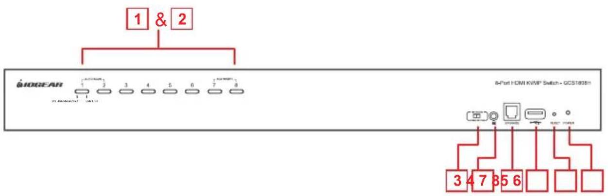
GCS1808H Front View
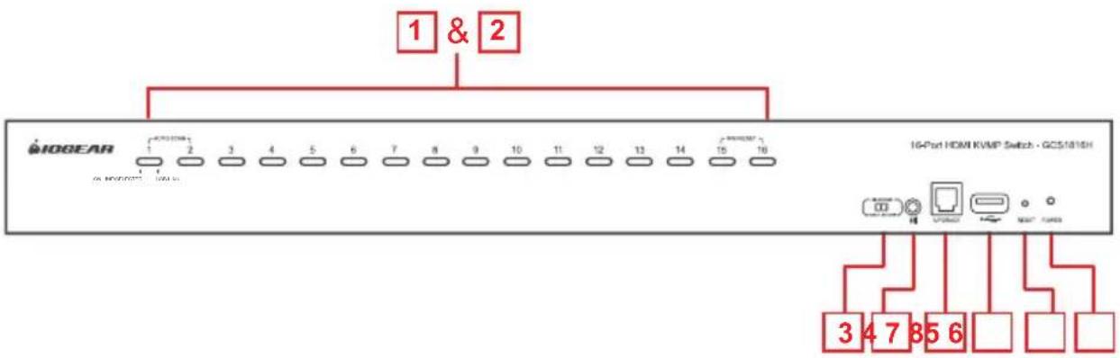
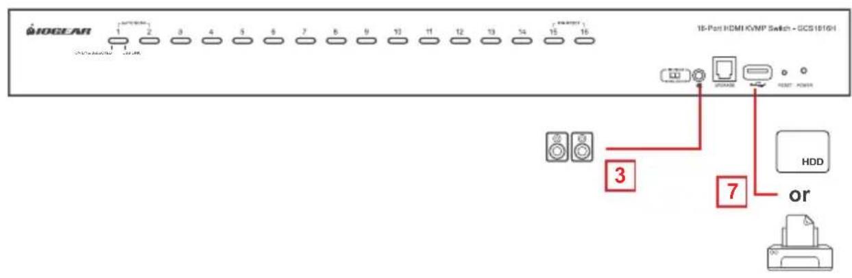
GCS1816H Front View
| No. | Component Description |
| 1 Port Selection Pushbuttons | For manual port selection:Press a port selection pushbutton for less than 2 seconds to bring the KVM, USB hub, and Audio focus to the computer connected to its correspondingportPress a pushbutton for longer than 2 seconds to bring the KVM and Audio focus to the computer connected to its corresponding portPress pushbuttons 1 and 2 simultaneously for 2 seconds to start Auto Scan ModePress pushbutton 7 and 8 (on GCS1808H) or 15 and 16 (on GCS1816H) simultaneously for 2 seconds to perform a Keyboard and Mouse Reset.Note:Mouse emulation must be enabled for independent switching to work (see page 44 for more details) |
| 2 Port LEDs Port LEDs are built into the Port Selection Switches. The left ones are the KVM Port LEDs; the right ones are the USB LEDs:KVM LEDsLights DIM ORANGE - indicates that the computer connected to the corresponding port is up and running (On Line)Flashes – indicates that Firmware Upgrade mode is in effectLights BRIGHT ORANGE – indicates that the computer connected to its corresponding port has the KVM focus (Selected)Flashes – indicates that the computer connected to its corresponding port is being accessed under Auto Scan ModeUSB LEDsLights GREEN - indicates that the computer connected to its corresponding port has access to the USB peripherals | |
| 3 Firmware Upgrade Recovery Switch | During normal operation and while performing a Firmware Upgrade, this recovery switch should be in the NORMAL position. If a Firmware Upgrade operation does not complete successfully, this switch will be used to perform a Firmware Upgrade recovery.See Firmware Upgrade Recovery for details |
| 4 Audio Port | Connect main speaker set to this audio port. Speakers connected to this port have priority over the ones connected to the audio port on the rear panel |
| 5 Firmware Upgrade Port | Connect the included firmware upgrade cable to this RJ-11 port to perform firmware update. Firmware upgrade data will be transferred from the administrator's computer to the GCS1808H/GCS1816H using this connection |
| 6 USB 2.0 Hub Connect the USB 2.0 peripherals (printers, scanners, etc.) to this USB 2.0 port (external power adapter may be required)Note: The USB 2.0 hub can only be accessed through the switch from sources on the 1st level of cascaded installation | |
| 7 Reset Switch | System reset can be performed by pressing this reset switch. When system is reset, the GCS1808H/GCS1816H beeps and the port LEDs flash in succession until the reset is complete. Please wait until reset is complete to login back to the OSD menu.Note: The reset switch is recessed and must be pushed using a small object, such as the end of a paper clip or a ballpoint pen |
| 8 Power LED Lights | up – indicates that the GCS1808H/GCS1816H is powered up and ready to operate |
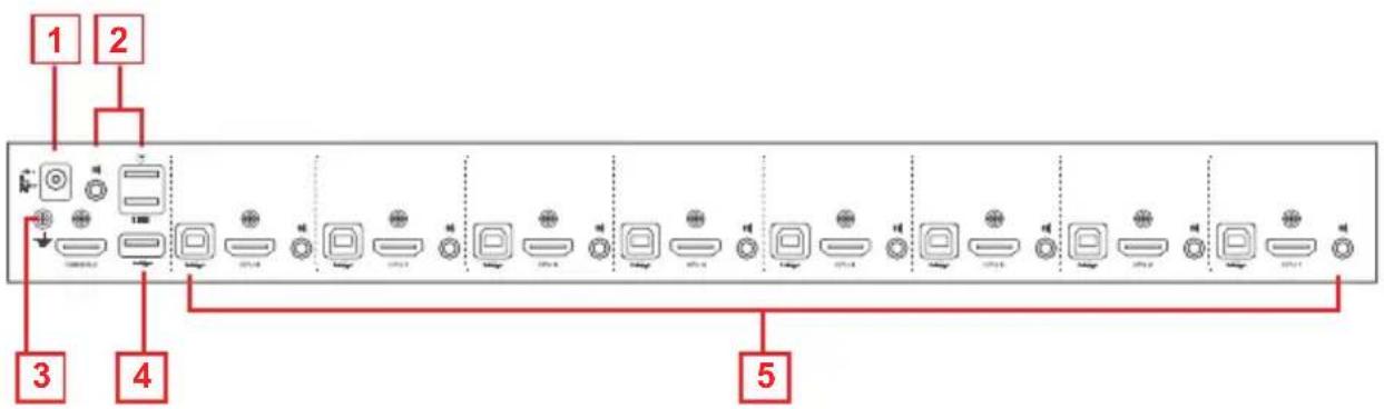
GCS1808H Rear View
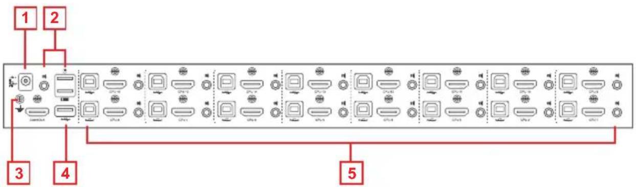
GCS1816H Rear View
| No. | Component Description |
| 1 P | Power Jack Connect the included power adapter to this power jack |
| 2 Console Port Section | Connect the console HDMI monitor, the USB keyboard, USB mouse, and secondary speakers set into this section. Each port is marked with the appropriate icons |
| 3 Grounding Terminal | Connect grounding wire here (optional) to ground the GCS1808H/GCS1816H |
| 4 USB 2.0 Hub | Connect the USB 2.0 peripherals (printers, scanners, etc.) to this USB 2.0 port (external power adapter may be required)Note: The USB 2.0 hub can only be accessed through the switch from sources on the 1st level of cascaded installation |
| 5 KVM Port Sections | Connect sources to these sections. Each KVM port section is comprised of a speaker jack, a USB Type-B socket, and an HDMI connector with screw lock.We recommend using IOGEAR's USB HDMI KVM Cable Set (G2L802U) for this installation |
Hardware Setup
Overview
IOGEAR's GCS1808H/GCS1816H package comes with 2 set of USB HDMI KVM cable sets (G2L802U) and GCS1808HKITU/GCS1816HKITU package comes with 8/16 set of USB HDMI KVM cable sets (G2L802U). Please contact your dealer to order additional KVM cables, as separate custom USB HDMI KVM cable is required for each computer connection.
Installation Types
IOGEAR's GCS1808H/GCS1816H offers 2 types of installation:
1) Single Installation or Cascade Installation – controlling up to 256 or 512 computers on one monitor
2) Multi-display Installation - controlling up to 7 or 15 computers on multiple monitors
Since multi-display installation requires different cabling setups, installation type 1) and type 2) will not be available in conjunction (or together).
Before You Begin

- Important safety information regarding the placement of this device is provided on page 56. Please review it before proceeding
- Please make sure that all devices that will be part of the installation are in OFF mode. Power cords of computer with keyboard on must be disconnected.
Stacking and Rack Mounting
IOGEAR's GCS1808H/GCS1816H can be stacked on the desktop or rack mounted at the front or rear of a 19" rack. The following sections will further detail the procedures of each method.
Note:
- When rack mounting, allow at least 2" on each side for adequate ventilations and 5" at the rear for power cord and cable clearance
- The standard rack mounting kit does not include the screws or cage nuts. Please contact your rack mount dealer for additional screw or cage nuts.
Stacking
The GCS1808H/GCS1816H can be placed on any surface level that can safely support its weight and the weight of the attached cables. Please make sure that the surface is clean and free of any materials that can block the exhaust vents or otherwise interfere with normal operation of the switch.
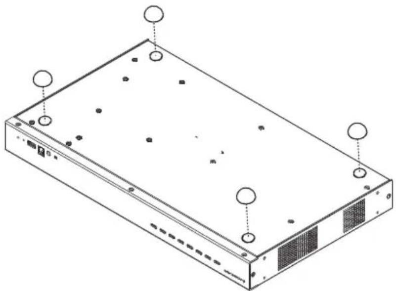
To place the GCS1808H/GCS1816H or to stack them in cascading setup, please use the included 4 piece of rubber footpads as shown below
Stacking
The GCS1808H/GCS1816H can be placed on any surface level that can safely support its weight and the weight of the attached cables. Please make sure that the surface is clean and free of any materials that can block the exhaust vents or otherwise interfere with normal operation of the switch.
To place the GCS1808H/GCS1816H or to stack them in cascading setup, please use the included 4 piece of rubber footpads as shown below
natural_image
Isometric line drawing of a server rack with labeled ports and mounting holes (no text or symbols)Basic Operation
Rack Mounting – Front
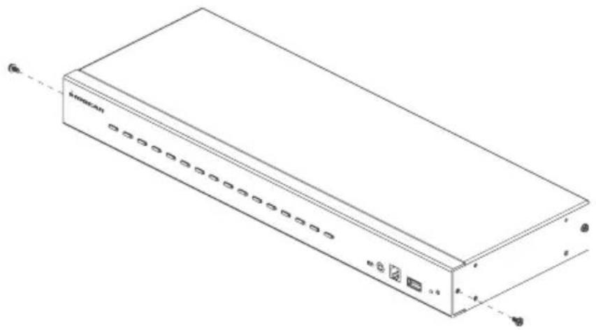
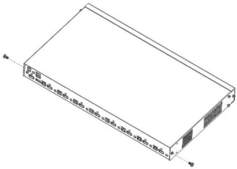
- Remove the screws, one each from the left and the right sides of the switch near the front of the switch
natural_image
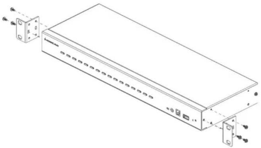
Line drawing of a rectangular electronic device with ports and indicator lights (no text or symbols)- Use the M3 x 8 Phillips hex head screws supplied with the rack mounting kit to screw the rack mounting brackets into the sides near the front of the switch
natural_image
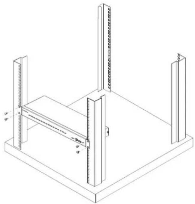
Line drawing of a network device with ports and connectors, no text or symbols present- Place the KVM switch into the rack. Position the switch so that the holes in the mounting brackets line up with the holes in the rack. Secure the mounting brackets to the front of the rack
natural_image
Isometric technical drawing of a structural frame assembly with vertical supports and a central horizontal beam (no text or symbols)Rack Mounting – Rear
- Remove the screws, one each from the left and the right sides of the switch near the rear of the switch
-
Use the M3 x 8 Phillips hex head screws supplied with the rack mounting kit to screw the rack mounting brackets into the sides near the rear of the switch
-
Place the KVM switch into the rack. Position the switch so that the holes in the mounting brackets line up with the holes in the rack. Secure the mounting brackets to the rear of the rack
natural_image
Isometric line drawing of a rectangular electronic device with ports and connectors (no text or symbols)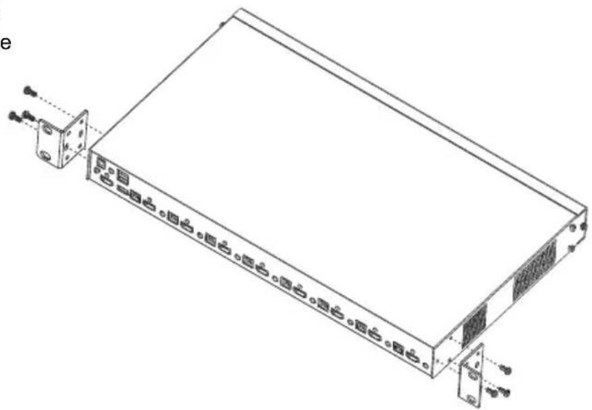
natural_image
Technical line drawing of a server rack with ports and connectors (no text or symbols)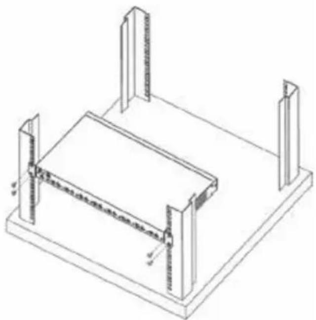
natural_image
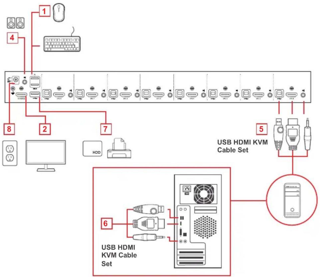
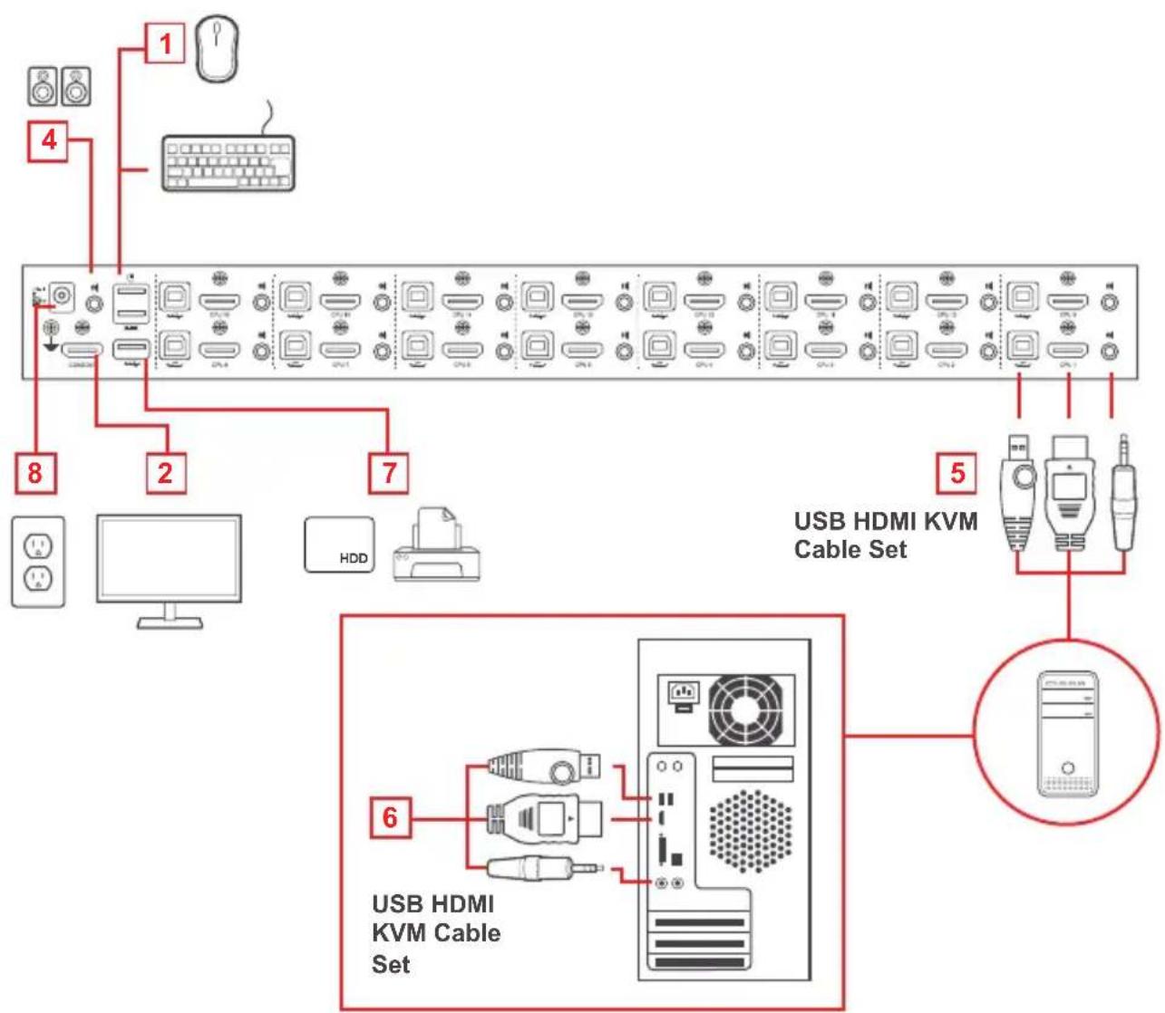
Isometric line drawing of a rectangular structure with vertical supports and a horizontal base, no text or symbols present.Please make sure that all devices including all preexisting devices on the installation are in OFF mode. Please refer to the installation diagram on page 17 to setup Single Stage GCS1808H/GCS1816H and follow below procedures:
- Connect the USB keyboard and USB mouse into the USB console ports located on the unit's rear panel
- Connect the HDMI monitor into the HDMI console port and turn the monitor power ON
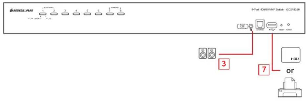
- Connect the main speakers set into the speaker jack located on the unit's front panel. Speaker sets connected into this port have priority over the ones connected into the rear panel
- Connect the secondary speakers set into the audio port located on the unit's rear panel
- Using the provided custom USB HDMI KVM cable sets, connect the HDMI connector to any available HDMI socket in the KVM port section located on the unit's rear panel. Then, connect the accompanying USB and audio connectors into their corresponding USB and speaker sockets.
Note:
- Verify that all cables are in the same KVM port sockets (all in Port 1, all in Port 2, etc.)
- The GCS1808H/GCS1816H only support speaker ports. Do not connect the microphone connector to the speaker port.
- At the other end of the cable, connect the USB, video, and speaker cables into their respective ports on the computer source
- Connect the USB peripherals into the USB Type-A port in the USB hub section
- Connect the power adapter that came with the package, into an AC power source, then connect the power adapter cable to the switch's Power Jack
- Turn all computer sources on.
Single Stage Installation Diagram
GCS1808H
flowchart
graph TD
    A["1"] --> B["2"]
    C["4"] --> D["7"]
    E["8"] --> F["PC 10"]
    G["2"] --> H["PC 11"]
    I["7"] --> J["PC 12"]
    K["5"] --> L["USB HDMI KVM Cable Set"]
    M["6"] --> N["USB HDMI KVM Cable Set"]
    O["HD"] --> P["HDD"]
GCS1816H
flowchart
graph TD
    A["1"] --> B["2"]
    C["4"] --> B
    D["8"] --> E["2"]
    F["7"] --> E
    G["5"] --> H["6"]
    I["USB HDMI KVM Cable Set"] --> J["6"]
    K["HDd"] --> L["Computer"]
    M["Server"] --> N["USB HDMI KVM Cable Set"]
    style A fill:#f9f,stroke:#333
    style C fill:#f9f,stroke:#333
    style D fill:#f9f,stroke:#333
    style E fill:#f9f,stroke:#333
    style F fill:#f9f,stroke:#333
    style G fill:#f9f,stroke:#333
    style H fill:#f9f,stroke:#333
    style I fill:#f9f,stroke:#333
    style J fill:#ccf,stroke:#333
    style K fill:#ccf,stroke:#333
    style L fill:#ccf,stroke:#333
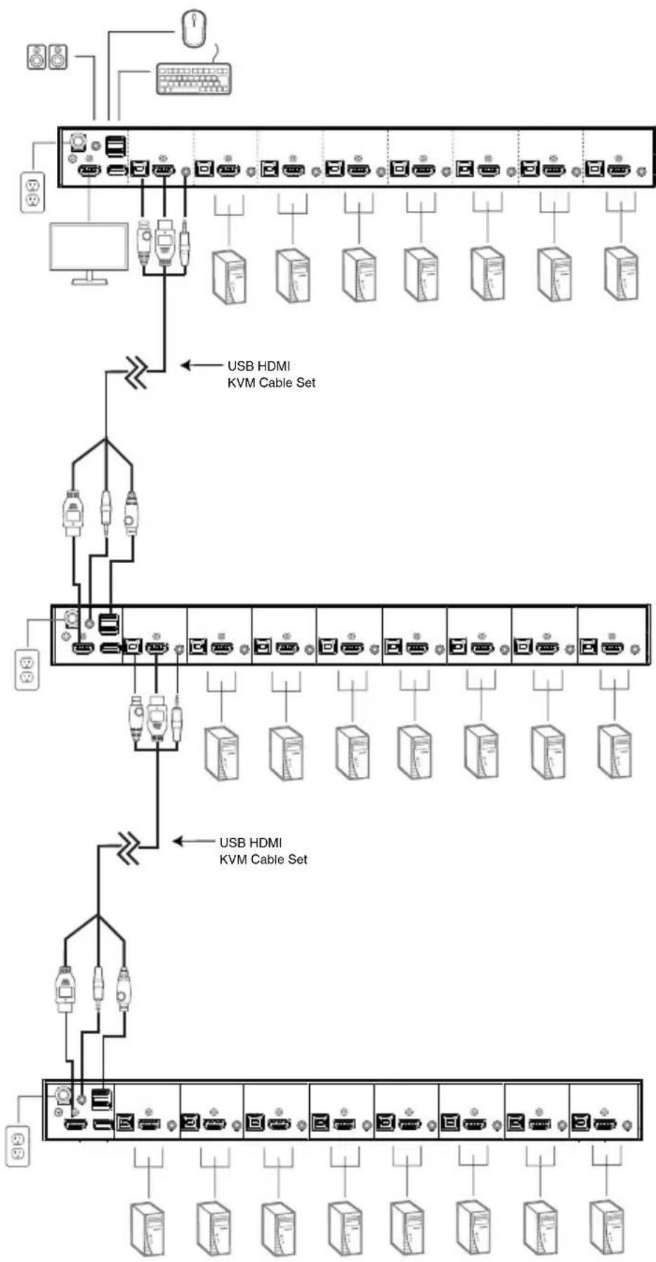
Two Stage (Cascade) Installation
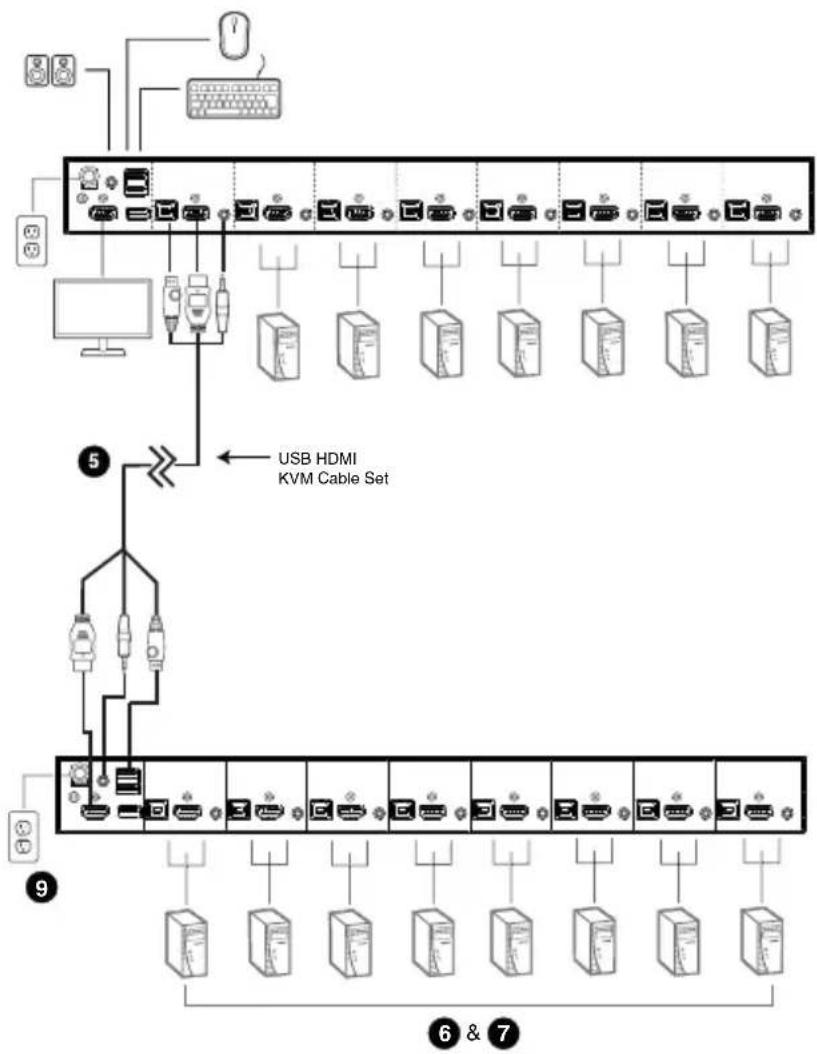
To control more than 8/16 computers, additional GCS1808H/GCS1816H can be cascaded from the KVM ports of the First Stage unit. The cascaded GCS1808H/GCS1816Hs that will be cascaded to the First Stage unit are considered as Second Stage units. As many as 64 computers (using cascaded GCS1808H) or 256 computers (using cascaded GCS1816H) can be controlled in a complete Two Stage installation. A table showing the relation between the number of computers and the number of units needed to control them is provided on page 54
Please make sure that all devices including all preexisting devices on the installation are in OFF mode. Please refer to the installation diagram on page 20 to setup Two Stage GCS1808H/GCS1816H and follow below procedures:
- Connect the USB keyboard and USB mouse into the USB console ports located on the unit's rear panel
- Connect the HDMI monitor into the HDMI console port and turn the monitor power ON
- Connect the main speakers set into the speaker jack located on the unit's front panel. Speaker sets connected into this port have priority over the ones connected into the rear panel
- Connect the secondary speakers set into the audio port located on the unit's rear panel
- Using the provided custom USB HDMI KVM cable sets, connect any available KVM port from the First Stage GCS1808H/GCS1816H to the Console ports of the Second Stage GCS1808H/GCS1816H.
Note: ____
Connect the USB Type-A connector into the lower USB keyboard port on the Console section
- Using a different set of custom USB HDMI KVM cable sets, connect the HDMI connector to any available HDMI socket in the KVM port section located on the Second Stage unit's rear panel. Then, connect the accompanying USB Type-B, and speaker connectors into their corresponding USB and speaker sockets.
Note:
- Verify that all cables are in the same KVM port sockets (all in Port 1, all in Port 2, etc.)
- The GCS1808H/GCS1816H only support speaker ports. Do not connect the microphone connector to the speaker port.
- At the other end of the cable, connect the USB Type-A, video, and speaker cables into their respective ports on the computer source
- Repeat steps 6 and 7 for any other computers that will be part of the installation
- For the Second Stage unit, connect the power adapter, that comes with the package,
into an AC power source, then connect the power adapter cable into the switch's Power Jack
-
For the First Stage unit, connect the power adapter, that came with the package, into an AC power source, then connect the power adapter cable into the switch's Power Jack
-
Turn all computer sources on
Note:
-
Power sequence requires that all Second Stage units be powered ON first. After all Second Stage units are powered on, then power on all the First Stage units. After the Second and First Stage units are powered on, then the sources can be red on.
-
The USB 2.0 hub can only be accessed through the switch from computer sources on the 1st level of a cascaded installation
Two Stage Installation Diagram
flowchart
graph TD
    A["Server Rack"] --> B["USB HDMI KVM Cable Set"]
    B --> C["Device 5"]
    C --> D["Device 9"]
    D --> E["Device 6 & 7"]
    style A fill:#f9f,stroke:#333
    style B fill:#ccf,stroke:#333
    style C fill:#cfc,stroke:#333
    style D fill:#fcc,stroke:#333
    style E fill:#cff,stroke:#333
Three Stage (Cascade) Installation (only for GCS1808H)
The steps for setting up a Three Stage installation are essentially the same as for a Two Stage installation. Using the GCS1808H (GCS1816H installation cannot exceed Two Stage) in a Three Stage setup, as many as 512 computer can be controlled in a complete installation. A table showing the relation between the number of computers and the number of units needed to control them is provided on page 54
Note:
- The GCS1808H cannot exceed Three Stage level cascade and the GCS1816H cannot exceed Two Stage level
- The GCS1808H can only be cascaded with another GCS1808H. The GCS1816H (set as the First Stage unit) can be cascaded with either GCS1808H or GCS1816H.
Once all cable connections are installed (please refer to Two Stage Cascade on page 19), then turn power ON based on the following sequence:
- For the Third Stage unit, connect the power adapter, that came with the package, Into an AC power source, then connect the power adapter cable into the switch's Power Jack
- For the Second Stage unit, connect the power adapter, that came with the package, into an AC power source, then connect the power adapter cable into the switch's Power Jack
- For the First Stage unit, connect the power adapter, that came with the package, into an AC power source, then connect the power adapter cable into the switch's Power Jack
- Turn all computer sources on
Note:
-
Power sequence requires that all Third Stage units be powered ON first. After all Third Stage units are powered on, then power on all the Second Stage units. After all Second Stage units are powered on, then power on all the First Stage units. After the Third, Second and First Stage units are powered on, then all sources can be powered on.
-
The USB 2.0 hub cannot be accessed through the switch from computer sources on the 2nd or 3rd level of a cascaded installation
Three Stage Installation Diagram
flowchart
graph TD
    A["Server Rack"] --> B["USB HDMI KVM Cable Set"]
    B --> C["Device 1"]
    B --> D["Device 2"]
    B --> E["Device 3"]
    B --> F["Device 4"]
    B --> G["Device 5"]
    B --> H["Device 6"]
    B --> I["Device 7"]
    B --> J["Device 8"]
    B --> K["Device 9"]
    B --> L["Device 10"]
    style A fill:#f9f,stroke:#333
    style B fill:#ccf,stroke:#333
    style C fill:#cfc,stroke:#333
    style D fill:#fcc,stroke:#333
    style E fill:#cff,stroke:#333
    style F fill:#ffc,stroke:#333
    style G fill:#cfc,stroke:#333
    style H fill:#fcc,stroke:#333
    style I fill:#ffc,stroke:#333
    style J fill:#cfc,stroke:#333
    style K fill:#fcc,stroke:#333
    style L fill:#ffc,stroke:#333
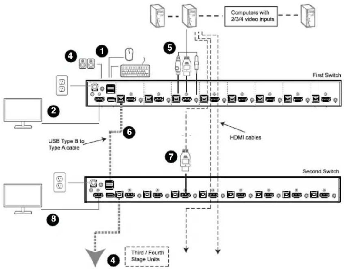
IOGEAR's GCS1808H/GCS1816H supports multi-display feature, allowing installation up to 8 monitors by stacking up to 8 units and controlling up to 7 (GCS1808H) or 15 (GCS1816H) computers at once. This installation requires different cabling compared to standard cascade. This setup offers an extra level of switching flexibility for multiple-monitors installations where each computer source is fitted with multiple video cards.
Note:
In a multi-display installation, the GCS1808H can only be stacked with other GCS1808H units and the GCS1816H can only be stacked with other GCS1816H units.
Cable Connections for Multi-Display Installation
Please make sure that all devices including all preexisting devices on the installation are in OFF mode. To setup multi-display installation, please refer to the installation diagram on the next page and follow below steps:
- Connect the USB keyboard and USB mouse into the USB console ports located on the First Stage unit's rear panel
- Connect an HDMI monitor to the console section of the First Stage unit
- Connect the main speakers set into the speaker jack located on the First Stage unit's front panel. Speaker sets connected into this port have priority over the ones connected into the rear panel
- Connect the secondary speakers set into the audio port located on the First Stage unit's rear panel
- Using the provided custom USB HDMI KVM cable sets, connect the HDMI connector to any available HDMI socket in the KVM port section located on the unit's rear panel. Then, connect the accompanying USB and audio connectors into their corresponding USB and speaker sockets.
Note: \_\_\_\_
- Verify that all cables are in the same KVM port sockets (all in Port 1, all in Port 2, etc.)
-
The GCS1808H/GCS1816H only support speaker ports. Do not connect the microphone connector to the speaker port.
-
Using a standard USB Type-A to Type-B cable, connect Port 8 USB Type-B ports on the First Stage unit to the USB Type-A port in the Console section on the Second Stage unit.
Note: \_\_\_\_
Port 8 is designed to connect the units in a multi-display installation. Up to 7 (GCS1808H) or 15 (GCS1816H) computers can be connected and controlled, using KVM Ports 1-7 (GCS1808H) or Ports 1-7 / 9-16 (GCS1816H)
- Using a separate HDMI cable, connect the HDMI KVM port from the Second Stage GCS1808H/GCS1816H to the second video input on the computer source.
Note:
Only HDMI video cables are needed for this installation – other ports in KVM section are not required in this installation
-
Connect an HDMI monitor to the console section of the Second Stage unit
-
Repeat steps 6-8 for any additional units, up to a total of 8 GCS1808H/GCS1816H
-
Please make sure that all Audio and peripheral devices are connected to the First Stage switch.
-
Turn ON the GCS1808H/GCS1816H units, starting with the First Stage unit. Then turn all computer sources
Multi-display Installation Diagram
flowchart
graph TD
    A["Computer"] --> B["First Switch"]
    C["User"] --> B
    D["USB Type B to Type A cable"] --> B
    E["Third / Fourth Stage Units"] --> F["Second Switch"]
    G["Computers with 2/3/4 video inputs"] --> H["Computers with 2/3/4 video inputs"]
    I["Hardware"] --> J["Hardware"]
    K["HDMI cables"] --> L["Hardware"]
    M["Device"] --> N["Device"]
    O["Computer"] --> P["Computer"]
Grouping ports into "Vertical" Channels
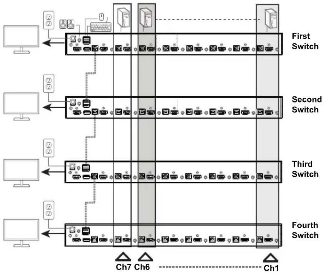
Once all cables have been connected and Multi-Display mode has been selected from the On-Screen Display (OSD), the GCS1808H/GCS1816H will auto-detect the channels and display mode. Users can then assign channel number as the power name (the channels are represented by the vertical columns in the diagram below). Therefore, all Port 1s become Channel 1, all Port 2s become Channel 2, and so on. The ports will be switched together or at the same time, channel by channel.
Depending on the number of Stage in the installation, GCS1808H/GCS1816H installation offers dual display (two stages), triple display (three stage), quad-display (four stages), up to multi-display (up to 8 stages) setup. For reference purposes, the example below shows a four-stage installation with quad-display functionality
Note:
Only one HDMI video signal can be displayed at a time, depending on the configuration of the GCS1808H/GCS1816H on the First Stage unit.
Channels Diagram for Quad-Display Setup
flowchart
graph TD
    A["Computer Monitor"] --> B["First Switch"]
    B --> C["Second Switch"]
    C --> D["Third Switch"]
    D --> E["Fourth Switch"]
    B --> F["Ch7"]
    C --> G["Ch6"]
    D --> H["Ch1"]
    style B fill:#f9f,stroke:#333
    style C fill:#f9f,stroke:#333
    style D fill:#f9f,stroke:#333
    style E fill:#f9f,stroke:#333
Hot Plugging
IOGEAR's GCS1808H/GCS1816H supports hot plugging – components can be removed and connected back into the installation by unplugging and plugging cables from and to the ports, without the need to turn the devices down. In order for hot plugging to work properly, please follow below procedures:
Hot Plugging KVM Ports
In order for the OSD menu to correspond to the KVM port changes, the OSD must be manually reconfigured to reflect the new port information. Please refer to F3: SET (on page 31) and F4: ADM (on page 33) functions for details.
Note: If the computer's operating system does not support hot plugging, this function may not work properly
Hot Plugging Console Ports
The keyboard, monitor, and mouse can all be hot-plugged.
When hot-plugging the mouse:
- Mouse may disconnected and reconnected (to reset the mouse for example), as long as the same mouse is being used
- If a different mouse is reconnected, then all of the computers in the installation must be shut down for 10 seconds then restarted following the power up sequence described under Two Stage Cascade, steps 9 - 11.
Note: If there is no response to the keyboard and/or mouse input after hot plugging, please perform a Keyboard and Mouse Reset by simultaneously pressing front panel pushbutton port 7 and 8 on GCS1808H or pushbutton 15 and 16 on GCS1816H for 2 seconds.
Port Selection
IOGEAR's GCS1808H/GCS1816H provides 3 convenient switching methods to access the computers that are part of the installation:
1. Manual Port Switching
Using the front panel pushbutton to manually switch to a port
2. On-Screen Display (OSD) menu system
Using the keyboard and mouse to navigate the OSD - a menu driven method to control computer and switching operations. All procedures begin from the OSD main screen. Default OSD Hotkey by pressing [Scroll Lock] key twice. Please see
Chapter 4 for OSD Operation for more details
3. Hotkeys combination
a. Press and hold down [Num Lock]
b. Press and release [-]
c. Release [Num Lock]
d. Enter Port number
e. Press [Enter]
Please see Chapter 5 for Hotkey Operation for more details
Port ID Numbering
Each port on IOGEAR's GCS1808H/GCS1816H's installation is assigned a unique Port ID. Users can directly access any computer on any level of the installation by specifying the Port ID that the computer is connect to – either via OSD (see OSD operation page 28) or via Hotkey port selection method (see Hotkey Operation, page 39)
Computers attached to the Master / First unit has a two digit Port ID
From 01 – 08 for GCS1808H or from 01 – 16 for GCS1816H) that corresponds to the KVM power number it is connected to
Computers attached to the Client / Second (or so forth) unit has a four digit Port ID.
The first two digits represent the KVM port number on the Master / First unit and the last two digits represent the KVM port number on the Client unit that it is connected to. For example, a Port ID of 02 – 08 would refer to a computer that is connected to KVM port 8 of the Second Client unit that links back to KVM port 2 of the Master / First unit.
Powering Off and Restarting
When it becomes necessary to power off a GCS1808H/GCS1816H, please do the following before restarting the unit:
- Disconnect the GCS1808H/GCS1816H from its power source
- Turn off all computers connected to the KVM Switch
Note: Disconnect all power cords of all connected computers that have the Keyboard Power On function. Otherwise, the GCS1808H/GCS1816H will still receive power from the connected computers
- Wait for 10 second, then connect the GCS1808H/GCS1816H back to its power source
- Turn on all computers connected to the KVM Switch
Note: If there are stations cascaded down from the Master / First GCS1808H/GCS1816H, then all cascaded stations and the connected computers must be turned off as well.
OSD Overview
The On-Screen Display (OSD) is a mouse and keyboard enabled – menu driven method used to control and switch connected computer's operations. All procedures begin from the OSD main screen.
OSD Login
The OSD incorporates a two level (administrator / user) password system. Before the OSD main screen appears, a login screen appears requiring a password. If this is the first time that the OSD is used, or if the password function has not been set, simply press [Enter] twice. The OSD main screen will display in administrator mode. In administrator mode, users will have administrator privileges, with access to all administrator and user functions, and can also set up operations (including password authorization) as needed. If the password function has been set, users must provide an appropriate administrator / user password in order to access the OSD.
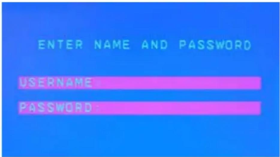
OSD Hotkey
Users can display the OSD on the console monitor while viewing the display of any computer connected on the GCS1808H/GCS1816H by pressing the [Scroll Lock] key twice.
Note: Users can optionally change the OSD hotkey to the [Ctrl] key (see OSD HOTKEY on page 32 for more details). With this method, the same [Ctrl] key must be used (cannot use the left [Ctrl] key and then the right [Ctrl] key)
OSD Main Screen
When OSD is invoked, a screen similar to below appears:
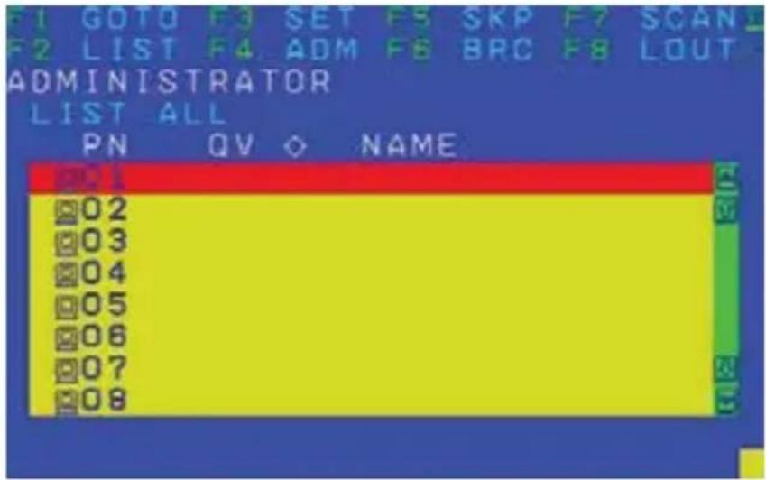
Note:
-
The diagram depicts the administrator's main screen. The user main screen does not show the F4 and F6 functions, since these are reserved for the administrator and cannot be accessed by users.
-
The OSD always begins in list view, with the highlighted bar at the same position as it was, the last time the OSD was closed
-
Current logged in users can only see ports that have been authorized by Administrator (see SET ACCESSIBLE PORTS on page 34)
-
If the port list is collapsed, click on a switch number or move the highlighted bar to it then press the right arrow key to expand the list. Similarly, to collapse a switch's port list, click on the switch number or move the highlighted bar then press the left arrow key to collapse the list.
OSD Main Screen Headings
| PN This column lists all port ID numbers for all KVM ports on the installation.The simplest method to access a particular computer is to move the highlighted bar to it, then press [Enter] |
| QV If a port has been selected for quick view scanning (see SET QUICK VIEW PORTS, page 35), then an arrowhead symbol will appear on this column |
 The computers that are powered on and are online have s sun symbol on this column The computers that are powered on and are online have s sun symbol on this column |
| NAME If a port has been given a name (see EDIT PORT NAMES, on page 35), then the name of the port will appear on this column |
OSD Navigation
- To dismiss the menu and deactivate the OSD without logging out, click X on the upper right corner of the OSD window or press [Esc]
- To log out of OSD, click F8 on the top of the main screen or press [F8]
- To move up or down through the list one line at a time, click the up and down triangle symbols (▲▼) or use the up and down arrow keys located on the right side of the OSD window. If there are more list entries than what appears on the main screen, the screen will scroll up or down.
- To move up or down through the list one screen at a time, click the up and down arrow (↑↓) symbols on the right side of the OSD window or use the [Pg Up] and [Pg Dn] keys. If there are more list entries than what appears on the main screen, the screen will scroll up or down
- To activate a port, double click the port or move the highlighted bar to it then press [Enter]
• After executing any action, users automatically return to the menu one level above
OSD Functions
OSD functions are used to configure and control the OSD. For example, users can rapidly switch to any port, scan selected ports, limit viewed list, designate a port as a quick view port, create or edit a port name, or make OSD setting adjustments.
To access an OSD function:
- Either click a function key field at the top of the main screen or press a function key on the keyboard
- In the submenus appeared, users can make the choice of either by double-clicking or by moving the highlighted bar to it, then press [Enter]
- Press [Esc] to return to the previous menu level
F1: GOTO
Selecting the F1 field or pressing [F1] activates the GOTO function. GOTO allows you to switch directly to a port either by keying in the port's Name or its Port ID. Mouse emulation must be enabled for independent switching (see page 44) for this GOTO function to work.
• To use the name method:
o Key in number 1; key in the port's Name then press [Enter] to switch KVM, Audio and USB focus or [Spacebar] to switch KVM and Audio only
• To use the port ID method:
o Key in number 2, key in the Port ID, then press [Enter] to switch KVM, Audio and USB focus or [Spacebar] to switch KVM and Audio only
Note: Users can key in a partial name or port ID. In that case, the screen will show all computers that users has VIEW rights to (see SET ACCESSIBLE PORTS page 34) that match the name or port ID pattern, regardless of the current list settings (see F2: LIST on page 31 for details)
To return to the OSD main screen without making a choice, press [Esc]
F2: LIST
This function allows users to broaden or narrow the scope of which ports the OSD displays on the main screen. The submenu details shown below
| SETTING FUNCTION | |
| ALL Lists all of the ports in the installation that have been set to accessible by the administrator for the current logged in user | |
| QUICK VIEW Lists only the ports that have been selected as Quick View ports (see SET QUICK VIEW PORTS page 35) | |
| POWERED ON Lists only the ports that have their connected computers powered on | |
| QUICK VIEW + POWERED ON Lists only the ports that have been selected as Quick View ports (see SET QUICK VIEW PORTS on page 35) and have their connected computers powered on |
Move the highlighted bar to the preferred choice then press [Enter]. An icon will appear before the choice to indicate that it is selected
F3: SET
This function enables the administrator and each user to set up his/her own working environment. A separate profile for each is stored by the OSD and is activated according to the username that was provided during the login.
To change a setting
- Double click on the item needed to be edited or move the highlighted bar to it then press [Enter]
- After an item is selected, a submenu with further choices will appear. To make a selection, either double click the selection or move the highlighted bar to the selection then press [Enter]. An icon will appear before the selected choice to indicate that it has been selected. The settings are explained in the following table:
| SETTING FUNCTION | |
| OSD HOTKEY Selects which | hotkey that will activate the OSD function:[Scroll Lock] [Scroll Lock] or [Ctrl][Ctrl]Default hotkey is [Scroll Lock] combination. Since the [Ctrl] key combination may conflict with programs running on the computers |
| PORT ID DISPLAY POSITION | Allows each user to customize the position where the port ID appears on the screen. The default is on the upper left corner but users can still choose to have it appear anywhere on the screen.Use the mouse or the arrow keys with Pg Up, Pg Dn, Home, End, and numeric keypad 5 (with Num Lock off), to position the Port ID display, then double-click or press [Enter] to lock the position and return to the Set submenu |
| PORT ID DISPLAY DURATION | Determines how long a port ID displays on the monitor after a port change has taken place.The choices are 3 Seconds (default) and Always Off |
| PORT ID DISPLAY MODE S | Selects how the port ID is displayed:• The port number plus the port name (PORT NUMBER + PORT NAME) (default)• The port number alone (PORT NUMBER)• The port name alone (PORT NAME) |
| SCAN DURATION | Determines how long the focus dwells on each port as it cycles through the selected ports in Auto Scan mode (see F7: SCAN, page 38. Key in a value from 1 – 255 seconds then press [Enter].Default value is 5 seconds; a setting of 0 disables the SCAN function.Note: Mouse emulation must be enabled for Auto Scan to work (see page 44) |
| SCAN-SKIP MODE | Selects which computers will be accessed under Skip Mode (see F5: SKP page 37) and Auto Scan Mode (see F7: SCAN page 38).Choices are:ALL – All the ports which have been set accessible (see SET ACCESSIBLE PORTS on page 34)QUICK VIEW – Only those ports which have been set accessible and have been selected as Quick View ports (see SET QUICK VIEW PORTS page 35)POWERED ON – Only those ports which have been set accessible and are powered onQUICK VIEW + POWERED ON – Only those ports which have been set accessible and have been selected as Quick View ports and are powered on. The default is ALLNote: The Quick View choices only show up on the administrator's screen since he/she has Quick View settings rights (see SET QUICK VIEW PORTS on page 35). Mouse emulation must be enabled for SCAN-SKIP mode to work (please see page 44) |
| SCREEN BLANKER If there | is no input from the console for the amount of time set with this function, the screen will turn blank. Key in a value from 1 – 30 minutes then press [Enter].Default setting of 0 disables this function. |
| HOTKEY COMMAND MODE | Enables / disables the hotkey command function in case a conflict with programs running on the computers occurs |
| HOTKEY Sets the keyboard | shortcut for invoking Hotkey Mode (see Hotkey Setting Mode on page 39). Choices are:[NUM LOCK] + [-] (default) or,[CTRL] + [F12] |
| OSD LANGUAGE Sets the language | language used in the OSD. Choices are:English (default)GermanJapaneseSimplified ChineseTraditional ChineseSpanishFrenchRussian |
F4: ADM
F4 is an administrator only function. This function allows the administrator to configure and control the overall operation of the OSD. To change a setting, double-click F4 or use the up and down arrow keys to move the highlighted bar then press [Enter]
After an item is selected, a submenu with further choices to select from will appear. Double click a selection or use the highlighted bar then press [Enter]. An icon will appear before the selected item. The settings are explained in the following table:
| SETTING FUNCTION | |
| SET USER LOGIN | This function is used to set usernames and passwords for the administrator and users:1. Usernames and passwords for 1 administrator and 4 users can be set2. After administrator field or one of the user fields is selected, a screen appears, allowing users to key in the user-name and password. Usernames and passwords can be from 1 to 16 characters long and consist of any combination of letters and numbers (A - Z, 0 - 9) and some special character keys (* () + : -, ?./ space)3. For each user, key in the user name and password. Confirm the password then press [Enter]4. To modify or delete a previous username and / or password, use the backspace key to erase individual letters or numbers. Press [Enter] when done.Note:Usernames and passwords are not case sensitive. Usernames are displayed in capital letters in the OSD |
| SET ACCESSIBLE PORTS | This function allows the administrator to define user access to the computers in the installation on a port-by-port basis.For each user, select the target port then press [Spacebar] to cycle through the choices:F (full access)V (view only)BlankRepeat until all access rights have been set then press [Enter].The default is F for all users on all ports.Note:A blank setting means that no access rights are granted. The port will not show up on the user's LIST on the main screenThe administrator always has full access to all ports |
| SET LOGOUT TIMEOUT | If there is no input from the console for the amount of time set with this function, the user is automatically logged out. A login is necessary before the console can be used again.This function enables other users to gain access to the computers when the original user is no longer accessing them but has forgotten to log out. To set the timeout value, key in a number from 1 - 180 minutes then press [Enter].The default setting of 0 disables this function.Note: This feature does not function if Set Login mode is disabled (See SET LOGIN MODE page 36) |
| EDIT PORT NAMES | To help remember which port is connected to which computer, every port can be given a name. This function allows the administrator to create, modify, or delete port names.To edit a port name:1. Click the port, or use the navigation keys to move the highlighted bar to the selected port then press [Enter]2. Key in the new port name or modify / delete the old one. The maximum number of characters allowed for the port name is 12 legal characters long and may consist of:All alpha characters: A – ZAll numeric characters: 0 – 9Special characters: * ( ) + : - , ? . /Name is not case sensitive, the OSD displays the port name all in capitals no matter how they were keyed in3. When port name editing is finished, press [Enter] to confirm changes. To abort changes, press [Esc] |
| RESTORE DEFAULT VALUES | This function allows users to undo all changes and return the setup to the original factory default settings (See Factory Default Hotkeys and Settings page 58) except for the port name list, username and password information. |
| CLEAR THE NAME LIST | This function will clear all port name list |
| ACTIVATE BEEPER | This is a toggle to turn ON (Y) or OFF (N) the beeper/buzzer sound.When activated, the beeper will sound whenever a port is selected, when activating the Auto Scan function (see F7: SCAN page 38) or when an invalid entry is made on OSD menu.Default Beeper is ON (Y) |
| SET QUICK VIEW PORTS | This function enables the administrator to select which ports to be included as Quick View ports:To select / deselect a port as a Quick View port, double click the port or move the highlighted bar to the port then press [Spacebar]When a port has been selected as a Quick View port, an icon will display under QV column of the LIST on the main screen. When a port is deselected, the icon will disappear.If one of the Quick View options is chosen for the LIST view (see F2: LIST page 31), only the selected port will be displayed on the listIf one of the Quick View options is chosen for Auto Scan (See SCAN-SKIP MODE page 32), only the selected port will be under Auto Scan mode.Default: no ports is selected for Quick View |
| SET OPERATING SYSTEM | This function allows the administrator to define the operating system for the computer connected to each KVM port.To set port's Operating System (OS):1. From the list, select the port that needs to have computer's OS set2. Set the OS by pressing [Spacebar] to cycle through Win, Mac, Sun, or Other3. Press [Esc] to exit. The OS you have selected is assigned to the KVM portDefault: Win (PC compatible) |
| FIRMWAREUPGRADE | Firmware Upgrade mode must first be enabled (see Firmware Upgrade page 48)When Firmware Upgrade menu is opened, the current firmware version level is displayed.Select Y to enable Firmware Upgrade mode or N to leave this menu without enabling it |
| KEYBOARDLANGUAGE | This function enables users to set the language used for the computer's keyboard connected to the KVM port. To select a keyboard language, double click on language chosen or use the navigation keys to move the highlighted bar to it then press [Enter]Language choices:AUTO (Default)ENGLISH (US)ENGLISH (UK)GERMAN (GER)GERMAN (SWISS)FRENCHHUNGARIANITALIANJAPANESEKOREANRUSSIANSPANISHSWEDISHTRADITIONAL CHINESESIMPLIFIED CHINESE |
| MOUSEEMULATION | Enables / Disables mouse emulation function.Mouse emulation must be enabled to perform any independent switching of a port and for Auto Scan Mode or Skip Mode to workNote: Only supported in the First Level of in installation. |
| ACTIVATEMULTI-DISPLAY | Enables Multi-Display Mode for dual, triple, up to 8 displays in Multiple-Monitor installations where each computer is fitted with multiple video cards (See Multi-Display installation on page 23 for more details)Note: Multi-Display Mode must be enabled on the OSD before the cables are connected |
| OSD CONFIGBACKUP /RESTORE | Enters OSD Configuration Backup / Restore Mode. The Firmware Management Utility allows users to backup the current OSD configuration of GCS1808H/GCS1816H and restore it when necessary.Storing the OSD configuration settings will be useful when deploying more than one installation that uses the same settings. (See OSD CONFIGURATION BACKUP/RESTORE page 52 for more details) |
| SET LOGIN MODE T | This function allows the administrator to request users' login access. When the Login dialog box is disabled, the system disables the Login/Logout function. If the system is re-started, the Login/Logout function remains disabled |
F5: SKP
Selecting F5 field or pressing [F5] will invoke Skip (SKP) Mode. This function enables users to easily skip backward or forward by switching the console focus from the currently active computer port to the previous or next accessible one. Mouse emulation must be enabled for Skip Mode to work (see Mouse Emulation on page 44)
The selection of computers available for Skip Mode Switching is made with the SCAN-SKIP mode setting under F3: SET function (see page 31)
When in Skip Mode:
- Press [ to Skip to the previous accessible port on the list
- Press [ ] to Skip to the next accessible port on the list
- Press [↑] to Skip to the next accessible port. If the next accessible port has cascaded a switch, then it will skip to the first accessible port of that switch
- Press [] to Skip to the previous accessible port. If the previous accessible port has cascaded a switch, then it will skip to the last accessible port of that switch
Note: Users can only skip to the previous or next accessible computer that is already in the SCAN-SKIP mode selection (see page 32)
- If a port has been selected for SCAN-SKIP Mode, then when the focus switches to that port, a (◀▶) appears before its port ID display. When the port ID with the triangle symbol displays, the background screen turns blank
- While Skip Mode is in effect, the console will not function normally. Users must exit skip mode in order to regain control of the console
- When the selected port appears, the Skip Mode is automatically disabled
- To exit Skip Mode, press [Spacebar] or [Esc]
F6: BRC
F6 is an administrator only function. Selecting F6 field or pressing [F6] will invoke Broadcast (BRC) mode. When this function is in effect, commands sent from the console are broadcasted to all available connected computers in the installation.
This function is particularly useful for operations that need to be performed on multiple computers, such as performing a system wide shutdown, installing or upgrading software, etc.
- While BRC Mode is in effect, a speaker symbol appears before the port ID that has the console focus. When the port ID with the speaker symbol appears, the background screen turns blank
- While BRC Mode is in effect, the mouse will not function normally. Administrator must exit BRC mode in order to regain control of the mouse
- To exit BRC Mode, invoke the OSD with the OSD hotkey, then select F6 field or press [F6] to turn BRC Mode off
- When BRC Mode is in effect, the Scroll Lock LED flashes. The LED will stop flashing and reverts to normal status when exiting BRC Mode
F7: SCAN
Selecting the F7 field or pressing [F7] invokes Auto Scan Mode. This function allows you to automatically switch among the available connected computers at regular intervals so users can monitor activities without switching to individual port. Mouse emulation must be enabled for Auto Scan to work (see page 44)
- The selection of computers to be included for Auto Scan is made with the SCAN-SKIP Mode setting under F3: SET function (see page 31)
- The amount of time that KVM dwell on each port is set with the SCAN DURATION setting under F3: SET function (see page 31). To stop at a particular port during Auto Scan Mode, press the [Spacebar] to stop scanning.
- If scanning stops on an empty port or on one where the computer is connected but is powered off, then the screen will show blank and the mouse/keyboard will have no effect. After the Scan Duration time is up, the KVM will move on and scan the next port
- As each connected computer is accessed, an S appears in front of the port ID display, indicating that the port is being accessed under Auto Scan Mode. When the port ID with the symbol appears, the background screen is blank
- While Auto Scan Mode is in effect, the console will not function normally. Users must exit Auto Scan Mode in order to regain control of the console
- While in Auto Scan Mode, users can pause scanning in order to keep the focus on a particular computer either by pressing P or pressing the left button of the mouse. See Invoking Auto Scan on page 40 for details.
- To exit Auto Scan Mode, press [Spacebar] or [Esc]
F8: LOUT
Selecting the F8 field or pressing [F8] will log user out of OSD control of the computers and console screen will show blank. This is different from simply pressing [Esc] from the main screen to deactivate the OSD.
With this function, users must log back in again in order to regain access to the OSD, whereas with [Esc], users can re-enter OSD menu by invoking OSD hotkey
Note:
- When re-entering OSD after logging out, the screen will stay blank except for the OSD main screen. Username and password must be entered before continuing
- If users re-enter the OSD after logging out and immediately use [Esc] to deactivate OSD without having to select a port from the OSD menu, a null port message will appear on the screen. The OSD hotkey will bring up the main OSD screen.
Hotkey Port Control
Hotkey port control allows the KVM to focus on a particular computer directly from the keyboard. The GCS1808H/GCS1816H provides the following hotkey port control features:
■ Selecting the Active port
■ Auto Scan Mode Switching
■ Skip Mode Switching
■ Computer Keyboard / Mouse Resetting
■ Enable / Disabling Mouse Emulation
The following settings can also be controlled in HSM mode;
■ Beeper
■ Quick Hotkey
■ OSD Hotkey
■ Port Operating System
■ OSD Default Values Restore
Note: Mouse emulation must be enabled to perform any independent switching of a port and for Auto Scan Mode or Skip Mode (please see page 40 and 44)
Hotkey Setting Mode
Hotkey Setting Mode is used to setup GCS1808H/GCS1816H switch configuration. All operations begins with invoking Hotkey Setting Mode (HSM).
Invoking HSM
- Press and hold down [Num Lock]
- Press and release [-]
- Release [Num Lock]
Or - Press and hold down [Ctrl] key
- Press and release [F12]
- Release [Ctrl]
When HSM is active:
■ A command line appears on the monitor screen. The command line prompt is the word Hotkey (in white text on a blue background) and displays the subsequent Hotkey information keyed in
- Ordinary keyboard and mouse functions are suspended – only hotkey compliant keystrokes can be input
■ Press [Esc] to exit HSM mode
Selecting an Active Port
Each KVM port is assigned with a port ID (see Port ID Numbering page 27). Users can directly access any computer in the installation with a hotkey combination that specifies the port ID of the KVM port that the computer is connected to.
To access a computer using hotkeys:
- Invoke HSM with [Num Lock] + [-] or [Ctrl] + [F12] combination
- Key in the Port ID
The Port ID number is displayed on the command line as keyed in. Use [Backspace] to erase previous entry.
3. Press [Enter]
After pressing [Enter], the KVM focus switches to the designated computer and automatically exit HSM.
Note: in HSM, KVM focus will not switch to a port if an invalid switch or port number is entered. The hotkey command line will continue to show on the screen until a valid switch and port number combination is entered or existing HSM
Auto Scan Mode
Auto Scan automatically switches between all KVM ports, at regular interval, that have been set as accessible under SCAN-SKIP Mode, so that their activities can be monitored automatically. See SCAN-SKIP Mode on page 32 for more detailed information
Invoking Auto Scan:
- Mouse emulation must be enabled (please see page 44)
- Invoke HSM with [Num Lock] + [-] or [Ctrl] + [F12] combination
- Press [A] then [Enter] to automatically exit HSM and enter Auto Scan Mode
- While in Auto Scan Mode, scanning can be paused in order to keep the focus on a particular computer, either by pressing P or left-click the mouse.
- During the time that scanning is paused, the command line will display:
Auto Scan: Paused
- Pausing is more convenient than exiting Auto Scan Mode because exiting and entering Auto Scan will start with the very first computer in the installation.
- To resume Auto Scan, press any key or left-click the mouse. Scanning continues where it left off
- While Auto Scan Mode is in effect, ordinary keyboard and mouse functions are suspended – only Auto Scan Mode compliant keystrokes and mouse clicks can be entered. Users must exit Auto Scan mode in order to regain normal control of the console
- To exit Auto Scan Mode, press [Esc] or [Spacebar].
Note: Mouse emulation must be enabled to perform any independent switching of a port and for Auto Scan Mode or Skip Mode to work (please see page 40 and 44)
Skip Mode
This feature enables users to switch between computers in order to monitor them manually. Users can dwell on a particular port as preferred – as opposed to Auto Scan Mode where users the KVM switches from one port to another after a fixed interval.
To invoke Skip More, key in the following hotkey combination:
- Mouse emulation must be enabled (please see page 44)
-
Invoke HSM with [Num Lock] + [-] or [Ctrl] + [F12] combination
-
Key in [Arrow]
Where [Arrow] refers to one of the arrow keys ( ). After pressing an arrow, users automatically exit HSM and enter Skip Mode, where switch ports can be done with the following:
| ← | Skips to the previous accessible port (See SCAN-SKIP Mode on page 32 for more detailed information |
| → | Skips to the next accessible port |
| ↑ | Skips to the previous accessible port. If the previous accessible port has a cascading switch, then it skips to the last accessible port of that switch |
| ↓ | Skips to the next accessible port. If the next accessible port has a cascading switch, then it skips to the first accessible port of that switch |
- When Skip Mode is in effect, users can keep on skipping by pressing the arrow keys. No need to use [Num Lock] + [-] combination again
- While Skip Mode is in effect, ordinary keyboard and mouse functions are suspended – only Skip Mode compliant keystrokes can be entered. Users must exit Skip Mode in order to regain normal control of the console
4. To exit Skip Mode, press [Esc] or [Spacebar]
Note: Mouse emulation must be enabled to perform any independent switching of a port and for Auto Scan Mode or Skip Mode to work (please see page 40 and 44)
Hotkey Beeper Control
The beeper/buzzer sound (see Activate Beeper on page 35) hotkey is a toggle that can be set on or off.
To toggle the beeper, key in the following hotkey combination:
- Invoke HSM with [Num Lock] + [-] or [Ctrl] + [F12] combination
- Press [B]
After pressing [B], the beeper toggles on or off. The command line displays Beeper On or Beeper Off for one second, then the message disappears and users automatically exit HSM
Quick Hotkey Control
The Quick Hotkey (see HOTKEY page 33) can be toggled between [Num Lock] + [-] and [Ctrl] + [F12]
To toggle between the two combination:
- Invoke HSM with [Num Lock] + [-] or [Ctrl] + [F12] combination
- Press [H]
After pressing [H], the command line displays HOTKEY HAS BEEN CHANGED for one second, then the message disappears and users automatically exit HSM
OSD Hotkey Control
The OSD Hotkey (see OSD HOTKEY page 32) can be toggled between [Scroll Lock] [Scroll Lock] and [Ctrl][Ctrl].
To toggle the OSD Hotkey, key in the following hotkey combination:
- Invoke HSM with [Num Lock] + [-] or [Ctrl] + [F12] combination
- Press [T]
After pressing [T], the command line displays HOTKEY HAS BEEN CHANGED for one second then the message disappears and users automatically exit HSM
Port OS Control
Port's Operating System (OS) can be edited to match the OS of the computer connected to that port.
To edit a port's OS, key in the following hotkey combination:
- Invoke HSM with [Num Lock] + [-] or [Ctrl] + [F12] combination
- Key in [Function], where [Function] refers to one of the function keys in the following table
| Key Description | |
| F1 Sets the Port OS to Windows | |
| F2 Sets the Port OS to Mac | |
| F3 Sets the Port OS to Sun |
After pressing a function key, users will automatically exit HSM
Restore Default Values
The administrator can restore GCS1808H/GCS1816H default values.
To restore default values:
-
Invoke HSM with [Num Lock] + [-] or [Ctrl] + [F12] combination
-
Press [R]
- Press [Enter]
After pressing [Enter], the command line displays RESET TO DEFAULT SETTING for three second then the message disappears and users automatically exit HSM
USB Reset
If the USB loses focus and needs to be reset, follow below steps:
- Invoke HSM with [Num Lock] + [-] or [Ctrl] + [F12] combination
- Press and release [F5]
Video DynaSync™
Video DynaSync™ is IOGEAR's exclusive technology that eliminates boot-up display problems and optimizes resolution when switching between ports or booting.
-
Invoke HSM with [Num Lock] + [-] or [Ctrl] + [F12] combination
-
Press [D]
Note: If the monitor is disconnected then reconnected, the GCS1808H/GCS1816H will re-execute Video DynaSync
Mouse Emulation Control
Default setting is enabled. This procedure is a toggle. To disable mouse emulation:
-
Invoke HSM with [Num Lock] + [-] or [Ctrl] + [F12] combination
-
Press [M]
Note: Mouse emulation must be enabled to perform any independent switching of a port and for Auto Scan or Skip Mode to work
HSM Summary Table
After invoking HSM (please see page 39), key in one of the following keys to perform the corresponding function
| Key Function | |
| [PN][Enter] Switches KVM, Audio | and USB focus directly to port [PN](PN = Port Number) |
| [PN][K][Enter] Switches KVM focus | us only directly to port [PN] |
| [PN][U][Enter] | Switches USB focus only directly to port [PN]Note: This hotkey functions only on the first level of an installation |
| [A][Enter] Starts Auto Scan. | KVM focus cycles from port to port at default 5 seconds interval |
| [A][n][Enter] Starts Auto Scan. | KVM focus cycles from port to port at n seconds interval(n = 1 - 255 seconds) |
| [H] Toggles between the default ([Num Lock][-]) and alternate([Ctrl][F12]) HSM invocation keys | |
| [T] Toggles between the default ([Scroll Lock][Scroll Lock])and alternate ([Ctrl][Ctrl]) OSD Hotkey | |
| [F1] Sets the port OS to Windows | |
| [F2] Sets the port OS to Mac | |
| [F3] Sets the port OS to Sun | |
| [F5] Performs a keyboard / mouse rest on the target computer | |
| [B] Enables/disables the beeper | |
| [R][Enter] Resets the hotkey settings to their default status. Please see Factory Default Hotkeys and Settings on page ## | |
| [D] Invokes Video DynaSync | TM, IOGEAR's exclusive technology that eliminates boot-up display problems and optimizes resolution when switching between ports |
| [M] Enables/disables mouse emulation | |
| [←] Skips to the previous computer on the list in Skip Mode | |
| [→] Skips to the next computer on the list in Skip Mode | |
| [↑] Skips to the next accessible port. If the next accessible port has cascaded a switch, then it skips to the first accessible port of that switch in Skip Mode | |
| [↓] Skips to the previous accessible port. If the previous accessible port has cascaded a switch, then it skips to the last accessible port of that switch in a Skip Mode | |
| [ESC] or [Spacebar] Exits Hotkey Setting Mode | |
Note: Mouse emulation must be enabled to perform any independent switching of a port and to perform Auto Scan Mode or Skip Mode
Keyboard Emulation
Mac Keyboard
The PC compatible (101/104 key) keyboard can emulate the functions of the Mac keyboard. The emulation mappings are listed in the table below
| Pc Keyboard Mac Keyboard | |
| [Shift] Shift | |
| [Ctrl] Ctrl | |
 |  |
| [Ctrl][1] |  |
| [Ctrl][2] |  |
| [Ctrl][3] |  |
| [Ctrl][4] |  |
| [Alt] Alt | |
| [Print Screen] F13 | |
| [Scroll Lock] F14 | |
| [HSTZ] | ### |
| [Enter] Return | |
| [Backspace] Delete | |
| [Insert] Help | |
[Ctrl]  |
Note: When using key combinations, press and release the first key [Ctrl] then press and release the activation key
Sun Keyboard
The PC compatible (101/104 key) keyboard can emulate the functions of the Sun keyboard when the Control key [Ctrl] is used in conjunction with other keys. The corresponding functions are shown in the table below
| Pc Keyboard Sun Keyboard | |
| [Ctrl][T] Stop | |
| [Ctrl][F2] Again | |
| [Ctrl][F2] Props | |
| [Ctrl][F4] Undo | |
| [Ctrl][F5] Front | |
| [Ctrl][F6] Copy | |
| [Ctrl][F7] Open | |
| [Ctrl][F8] Paste | |
| [Ctrl][F9] Find | |
| [Ctrl][F10] Cut | |
| [Ctrl][F1] |  |
| [Ctrl][F2] - |  |
| [Ctrl][F3] + |  |
| [Ctrl][F4] | [ATTY] |
| [Ctrl][H] Help | |
| [7ST0] | Compose |
| [ASKX] | ◆ |
Note: When using key combinations, press and release the first key [Ctrl] then press and release the activation key
Introduction
The purpose of Windows-based Firmware Management Utility is to provide an automated process for upgrading all GCS1808H/GCS1816H switches in an installation. The program comes as part of a Firmware Upgrade Package that is specific for each device.
As new firmware versions become available, new firmware upgrade packages are posted on IOGEAR's website www.iogear.com. Please check the website regularly to find the latest information and firmware upgrade packages.
Downloading the Firmware Upgrade Package
-
From a computer that is not part of the KVM installation, please go to IOGEAR's website www.iogear.com and choose the model name that relates to the device. A list of available firmware upgrade packages will appear.
-
Choose the firmware upgrade package that user wish to install (usually the most recent) and download it to the computer
Preparation
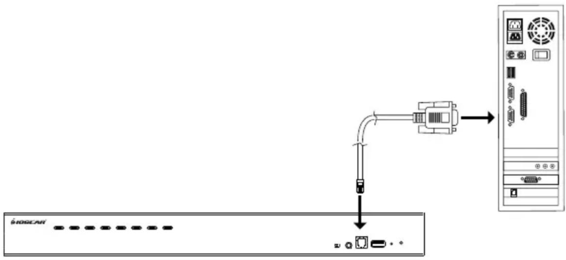
- Use the Firmware Upgrade Cable provided with the GCS1808H/GCS1816H/GCS1808HKITU/GCS1816HKITU package to connect a COM port on the computer to the Firmware Upgrade Port on the KVM switch
flowchart
graph TD
    A["Switch"] --> B["Server"]
    style A fill:#f9f,stroke:#333
    style B fill:#ccf,stroke:#333
- Turn off all computers that are part of the KVM installation
- From the KVM switch console, please login to the OSD as the Administrator (see page 28) and select F4: ADM function
- Scroll down to FIRMWARE UPGRADE. Press [Enter] then press [Y] to invoke Firmware Upgrade Mode (see page 36)
Starting the Upgrade Procedure
- Run the downloaded firmware upgrade package file either by double clicking the file icon or by opening a command line and entering the full path.
The Firmware Upgrade Utility welcome screen appears
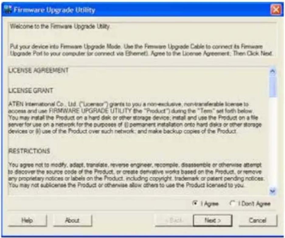
Note: The screens shown in this section are for reference only. Wording and layout of the actual screens of the Firmware Upgrade Utility may vary slightly from these images.
-
Read and choose "I Agree" from the License Agreement
-
Click Next to continue. The Firmware Upgrade Utility main screen will appear. The devices capable of being upgraded are listed under Device List panel
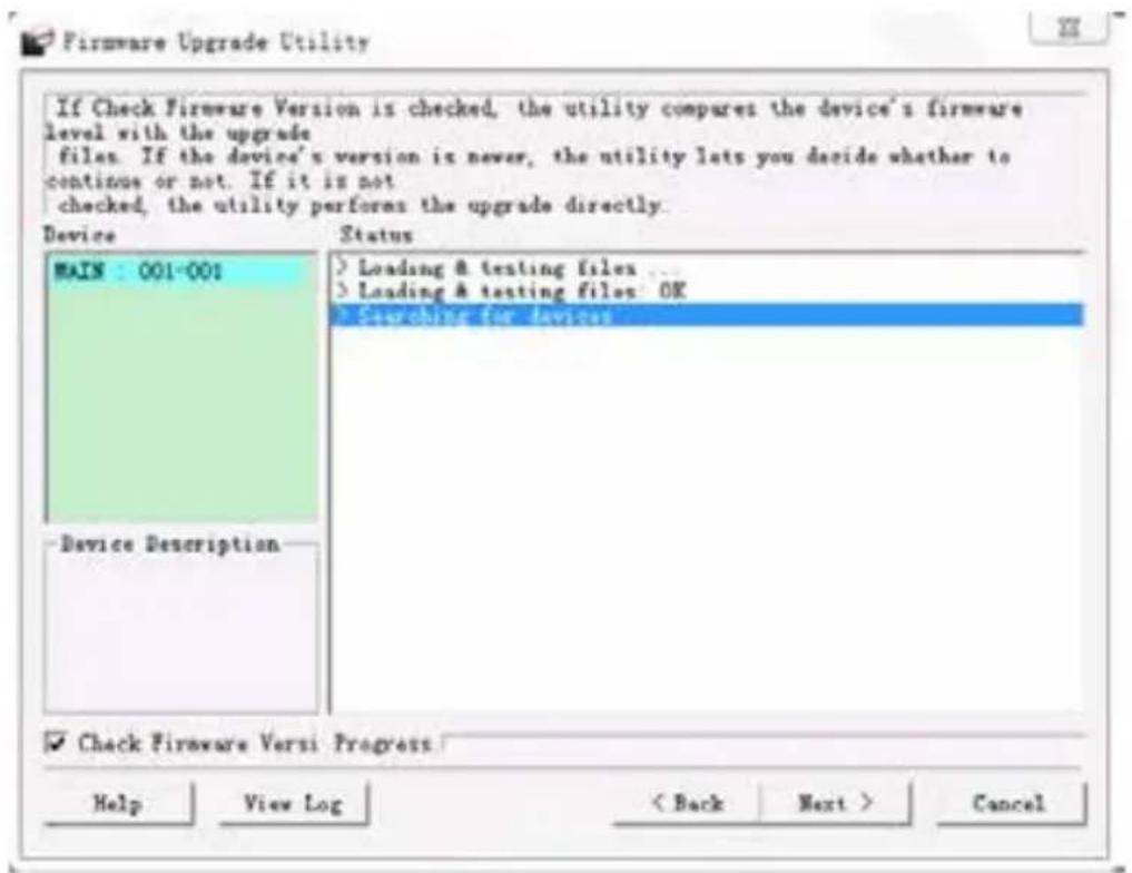
- Click Next to perform the upgrade
- If Check Firmware Version is enabled, then the Utility will compare the device's firmware level with that of the upgrade firmware. If the Utility finds that the device's firmware version is higher than the upgrade version, then it will bring up a dialog box informing the situation and gives the option to Continue [Yes] or to Cancel [No]
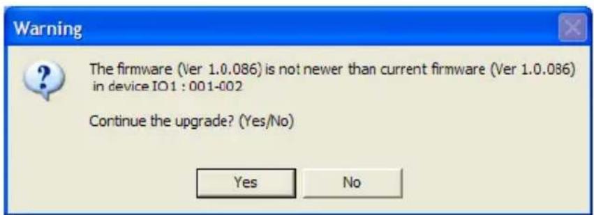
If Check Firmware Version is not enabled, then the Utility will install the firmware file upgrade without checking version level.
As the upgrade proceeds, status message will appear in the Status Messages panel, and then the progress towards completion is shown on the Progress bar
Upgrade Succeeded
After the upgrade has been completed, a screen will appear to inform that the procedure was successful.
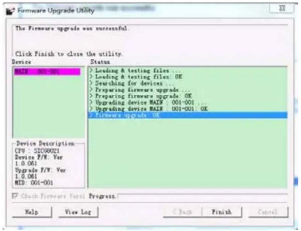
Click Finish to close the Firmware Upgrade Utility
Upgrade Failed
If the Upgrade Succeeded screen does not appear, this means that the upgrade failed to complete successfully.
Please see next section Firmware Upgrade Recovery on how to proceed.
Firmware Upgrade Recovery
There are three conditions that calls for Firmware Upgrade Recovery:
■ When a firmware upgrade is manually aborted
■ When the mainboard firmware upgrade fails
■ When the I/O firmware upgrade fails
To perform a Firmware Upgrade Recovery, please follow below steps:
- Turn the GCS1808H/GCS1816H power OFF
- Connect the Firmware Upgrade Cable to the Firmware Upgrade Port on the GCS1808H/GCS1816H
-
Slide the Firmware Upgrade Recovery Switch to the RECOVER position
-
Turn the GCS1808H/GCS1816H power back ON and repeat the Upgrade Procedure (see page 49)
- After the firmware has been successfully upgraded, turn the GCS1808H/GCS1816H power OFF and slide the Firmware Upgrade Recovery Switch back to NORMAL position
- If the KVM switch is part of the cascaded switches, please connect it back into the installation
- Turn the GCS1808H/GCS1816H power ON
OSD Configuration Backup/Restore
The Firmware Management Utility allows for current OSD configuration backup on the GCS1808H/GCS1816H and restore it when necessary. Storing the OSD configuration settings is useful when deploying more than one installation that uses the same settings.
Backup Procedure
Please follow below steps to restore a backup file to a local computer:
- Please make sure that the computer is connected to the GCS1808H/GCS1816H. See Preparation on page 48 and follow steps 1 – 3
- When F4: ADM function is selected, scroll down to OSD CONF BACKUP / RESTORE. Press [Enter] then press [Y] to invoke OSD Configuration Backup / Restore Mode
- Run the Firmware Management Utility. In the dialog box, choose OSD Configuration Backup / Restore, then click Next
- OSD Configuration Backup/Restore window will appear. Please choose Connect to connect device
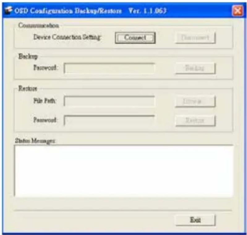
- In the password field, key in a password for the file
Note: Setting a password is optional. If password is not set, then the file can be restored without specifying a password
-
Click Backup
-
Select Save to Disk when prompted and save the file in a convenient location.
Restore Procedure
Please follow below steps to restore a backup file from a local computer:
- Follow steps 1 - 3 from previous section Backup.
- Click Restore to recover an OSD Configuration stored in a local computer. If a password has been previously set for this feature, then enter the password in the provided field before clicking Restore.
- A confirmation window will appear, please click Yes to proceed
- Browse for the OSD configuration file and click Restore. Please make sure that the backup file is in the local computer
- A confirmation window will appear when the restore process is done and successful. Click OK to close the window
The following tables indicate the relationship between the number of Master View units and the number of computers that they control:
GCS1808H
| MVs Computers MVs Computers MVs Computers MVs Computers | ||||||
| 1 1 - 8 | 20 134 - 141 | 39 267 - 274 | 58 400 - 407 | |||
| 2 8 - 15 | 21 141 - 148 | 40 274 - 281 | 59 407 - 414 | |||
| 3 15 - | 22 22 148 - 155 | 41 281 - 288 | 60 414 - 421 | |||
| 4 22 - | 29 23 155 - 162 | 42 288 - 295 | 61 421 - 428 | |||
| 5 29 - | 36 24 162 - 169 | 43 295 - 302 | 62 428 - 435 | |||
| 6 36 - | 43 25 169 - 176 | 44 302 - 309 | 63 435 - 442 | |||
| 7 43 - | 50 26 176 - 183 | 45 309 - 216 | 64 442 - 449 | |||
| 8 50 - | 57 27 183 - 190 | 46 316 - 323 | 65 449 - 456 | |||
| 9 57 - | 64 28 190 - 197 | 47 323 - 330 | 66 456 - 463 | |||
| 10 64 - | 71 29 197 - 204 | 48 330 - 337 | 67 463 - 470 | |||
| 11 71 - | 78 30 204 - 211 | 49 337 - 344 | 68 470 - 477 | |||
| 12 78 - | 85 31 211 - 218 | 50 344 - 351 | 69 477 - 484 | |||
| 13 85 - | 92 32 218 - 225 | 51 351 - 358 | 70 484 - 491 | |||
| 14 92 - | 99 33 225 - 232 | 52 358 - 365 | 71 491 - 498 | |||
| 15 99 - | 106 34 232 - 239 | 53 365 - 372 | 72 498 - 505 | |||
| 16 106 - | 113 35 239 - 246 | 54 372 - 379 | 73 505 - 512 | |||
| 17 113 - | 120 36 246 - 253 | 55 379 - 386 | ||||
| 18 120 - | 127 37 253 - 260 | 56 386 - 393 | ||||
| 19 127 - | 134 38 260 - 267 | 57 393 - 400 | ||||
GCS1816H
| MVs Computers MVs | Computers | MVs Computers | MVs Computers | Computers | ||
| 1 | 1 – 16 | 5 | 63 – 79 | 9 | 127 – 143 | 13 |
| 2 | 16 – 31 | 6 | 79 – 95 | 10 | 143 – 159 | 14 |
| 3 | 31 – 47 | 7 | 95 – 111 | 11 | 159 – 175 | 15 |
| 4 | 47 – 63 | 8 | 111 - 127 | 12 | 175 - 191 | 16 |
Specifications
| Function GCS1808H GCS1816H | |||
| Computer Connections | Direct 8 16 | ||
| Maximum 512 (via cascade) 256 (via cascade) | |||
| Port Selection OSD, Hotkey, Pushbutton | |||
| Connectors C | Console Ports | Keyboard 1 x USB Type-A Female | |
| Video 1 x HDMI Female | |||
| Mouse 1 x USB Type-A Female | |||
| Speakers 1 x 3.5 mm Stereo Jack Female (1 x Front Panel, 1 x Rear Panel) | |||
| KVM Ports | Keyboard / Mouse | 8 x USB Type B Female 16 x USB Type B Female | |
| Video 8 x HDMI Female 16 x HDMI Female | |||
| Speakers | 8 x 3.5 mm Stereo Jack Female | ||
| F/W Upgrade | 1 x RJ11 Female | ||
| Power | 1 x DC Jack | ||
| USB 2.0 Hub | 2 x USB Type-A Female (1 x Front Panel, 1 x Rear Panel) | ||
| Switches | Port Selection | 8 x Pushbutton | |
| Reset 1 x Semi-recessed Pushbutton | |||
| F/W Upgrade | 1 x Slide Switch | ||
| LEDs | USB Link | 8 (Green) | |
| On Line / Selected | 8 (Orange) 16 (Orange) | ||
| Power | 1 (Dark Green) | ||
| Emulation | Keyboard / Mouse | USB | |
| Video | 480i, 480p, 720p, 1080i, 1080p (HDTV) / 1920 x 1200 @ 60Hz | ||
| Scan Interval 1 - 255 Seconds (Default: 5 seconds) | |||
| Power Consumption | DC 5.0V; 12.0W | ||
| Environment | Operating Temperature | 0 - 50°C | |
| Storage Temperature | -20 - 60°C | ||
| Humidity | 0 - 80% RH, Non-condensing | ||
| Physical Properties | Housing | Metal | |
| Weight | 7.68lb (3.49kg) | ||
| Dimensions (L x W x H) | 17" x 10.1" x 1.73"(43.72cm x 25.66cm x 4.4cm) | ||
General
■ This product is for indoors use only
- Read all of these instructions. Save them for future reference.
■ Follow all warnings and instructions marked on the device.
■ Do not place the device on any unstable surface (card, stand, table, etc.). If the device falls, serious damage will result
■ Do not use the device near water
■ Do not place the device near, or over, radiators or heat registers
■ The device cabinet is provided with slots and openings to allow for adequate ventilation. To ensure reliable operation, and to protect against overheating, these openings must never be blocked or covered.
■ The device should never be placed on a soft surface (bed, sofa, rug, etc.) as this will block its ventilation openings. Likewise, the device should not be placed in a built-in enclosure unless adequate ventilation has been provided
■ Never spill liquid of any kind on the device
■ Unplug the device from the wall outlet before cleaning. Do not use liquid or aerosol cleaners. Use a damp cloth for cleaning
■ The device should be operated from the type of power source indicated on the marking label. If you are not sure of the type of power available, please consult your dealer or local power company
■ The device is designed for IT power distributions systems with 230V phase-to-phase voltage
■ To prevent damage to your installation, it is important that all devices are properly grounded
■ The device is equipped with a 3-wire grounding type plug. This is a safety feature. If you are unable to insert the plug into the outlet, please contact your electrician to replace your obsolete outlet. Do not attempt to defeat the purpose of the grounding-type plug. Always follow your local/national wiring codes
■ Do not allow anything to rest on the power cord or cables. Route the power cord and cables so that they cannot be stepped on or tripped over
■ If an extension cord is used with this device, please make sure that the total Ampere ratings of all products used on this cord does not exceed the extension cord Ampere rating. Please make sure that total products plugged into the wall outlet do not exceed 15 Amperes.
■ To help protect your system from sudden, transient increases and decreases in electrical power, please use a surge suppressor, line conditioner, or un-interruptible power supply (UPS)
■ Position system cables and power cables carefully. Please make sure that nothing rest on any of the cables
■ Never push objects of any kind into or through cabinet slots. They may touch dangerous voltage points or short out parts, resulting in a risk of fire or electrical shock
■ Do not attempt to service the device yourself. Please refer all servicing to qualified service personnel
■ If the following conditions occur, please unplug the device from the wall outlet and bring it to qualified service personnel for repair
o The power cord or plug has become damaged or frayed
o Liquid has been spilled into the device
o The device has been exposed to rain or water
o The device has been dropped, or the cabinet has been damaged
o The device exhibits a distinct change in performance, indicating a need for service
o The device does not operate normally when the operating instructions are followed
■ Only adjust those controls that are covered in the operating instructions. Improper adjustment of other controls may result in damage that will require extensive work by a qualified technician to repair
■ Do not connect the RJ-11 connector marked "UPGRADE" to a public telecommunication network
Factory Default Hotkeys and Settings
| Setting Hotkey Default | ||
| OSD Hotkey (Default / Alternate) [T] [Scroll Lock] [Scroll Lock] | ||
| Invoking HSM [H] [Number Lock] [-] | ||
| Auto Scan Interval [A][Enter] 5 seconds | ||
| Mouse Emulation [M] Enabled | ||
| Port Switching Keys (On / Off) [X][Enter] | Enabled | |
| Beeper [B] Enabled | ||
| Video DynaSyncTM [D] Enabled |
Administrator Login Failure
If you are unable to perform an Administrator login (because the username/ password information has become corrupted, or you have forgotten it, for example), you can clear the login information with the following procedure:
- Power off the GCS1808H / GCS1816H and remove its housing.
- Short the jumper labeled J29.
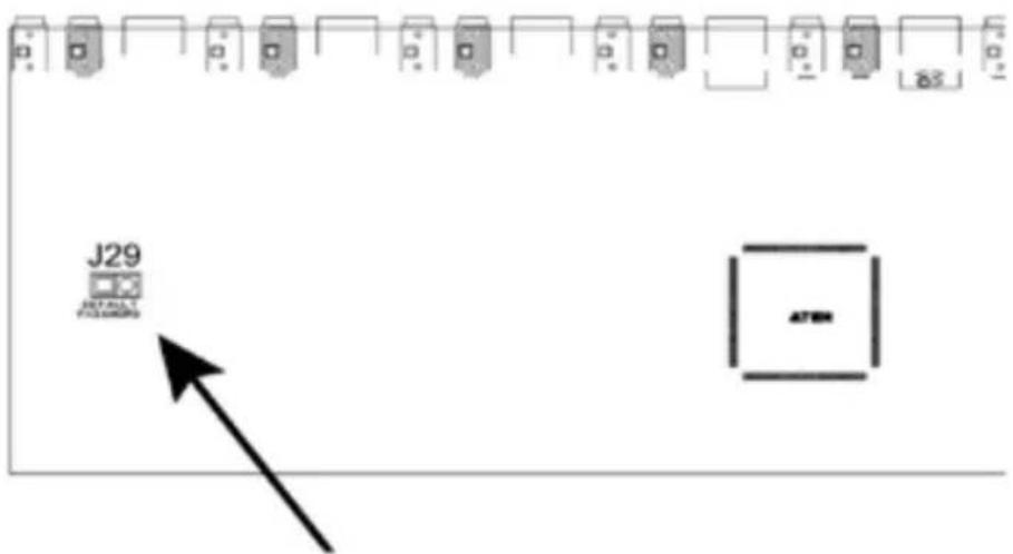
- Power on the switch.
- When the front panel LEDs flash, power off the switch.
- Remove the jumper cap from J29.
- Close the housing and start the GCS1808H / GCS1816H back up. Then, use the default login procedure (see OSD Login, page 28) to login.
FEDERAL COMMUNICATIONS COMMISSION INTERFERENCE STATEMENT
This equipment has been tested and found to comply with the limits for a Class A digital device, pursuant to Part 15 of the FCC Rules. These limits are designed to provide reasonable protection against harmful interference when the equipment is operated in a commercial environment. This equipment generates, uses, and can radiate radio frequency energy and, if not installed and used in accordance with the instruction manual, may cause harmful interference to radio communications. Operation of this equipment in a residential area is likely to cause harmful interference in which case the user will be required to correct the interference at his/her own expense.
The device complies with Part 15 of the FCC Rules. Operation is subject to the following two conditions:
(1) this device may not cause harmful interference, and
(2) this device must accept any interference received, including interference that may cause undesired operation.
CE Statement
This device has been tested and found to comply with the following European Union directives: Electromagnetic Capability (2004/108/EC), Low Voltage (2006/95/EC) and R&TTED (1999/5/EC).
RoHS
This product is RoHS compliant
Limited Warranty
Warranty Information
This product carries a 3 Year Limited Warranty. For the terms and conditions of this warranty, please go to https://www.iogear.com/support/warranty
Register online at https://www.iogear.com/registration
Important Product Information
Product Model
Serial Number ____
Contact
WE'RE HERE TO HELP YOU! NEED ASSISTANCE SETTING UP THIS PRODUCT?
Make sure you:
- Visit www.iogear.com for more product information
- Visit www.iogear.com/support for live help and product support
IOGEAR
www.iogear.com
https://iogear.custhelp.com
support@iogear.com

- Package Contents
- GCS1808H/GCS1816H
- GCS1808HKITU/GCS1816HKITU
- Overview
- Note:
- Requirements
- Console
- Computers
- Cables
- Operating Systems
- Features
- Hardware Setup
- Installation Types
- Before You Begin
- Stacking and Rack Mounting
- Stacking
- Basic Operation
- Rack Mounting – Front
- Rack Mounting – Rear
- Single Stage Installation Diagram
- Two Stage (Cascade) Installation
- Three Stage (Cascade) Installation (only for GCS1808H)
- Cable Connections for Multi-Display Installation
- Note: \_\_\_\_
- Multi-display Installation Diagram
- Grouping ports into "Vertical" Channels
- Hot Plugging
- Hot Plugging KVM Ports
- Hot Plugging Console Ports
- Port Selection
- Manual Port Switching
- On-Screen Display (OSD) menu system
- Chapter 4 for OSD Operation for more details
- Hotkeys combination
- Port ID Numbering
- Powering Off and Restarting
- OSD Overview
- OSD Login
- OSD Hotkey
- OSD Main Screen
- OSD Main Screen Headings
- OSD Navigation
- OSD Functions
- F1: GOTO
- F2: LIST
- F3: SET
- To change a setting
- F4: ADM
- F5: SKP
- When in Skip Mode:
- F6: BRC
- F7: SCAN
- F8: LOUT
- Hotkey Port Control
- Hotkey Setting Mode
- Invoking HSM
- When HSM is active:
- Selecting an Active Port
- Press [Enter]
- Auto Scan Mode
- Invoking Auto Scan:
- Auto Scan: Paused
- Skip Mode
- To exit Skip Mode, press [Esc] or [Spacebar]
- Hotkey Beeper Control
- Quick Hotkey Control
- OSD Hotkey Control
- Port OS Control
- Restore Default Values
- USB Reset
- Video DynaSync™
- Mouse Emulation Control
- HSM Summary Table
- Keyboard Emulation
- Mac Keyboard
- Sun Keyboard
- Introduction
- Downloading the Firmware Upgrade Package
- Preparation
- Starting the Upgrade Procedure
- Upgrade Succeeded
- Upgrade Failed
- Firmware Upgrade Recovery
- OSD Configuration Backup/Restore
- Backup Procedure
- Restore Procedure
- General
- Factory Default Hotkeys and Settings
- Administrator Login Failure
- FEDERAL COMMUNICATIONS COMMISSION INTERFERENCE STATEMENT
- CE Statement
- RoHS
- Limited Warranty
- Warranty Information
- Contact
- IOGEAR
Brand : IOGEAR
Model : GCS1816
Category : KVM switch