
FM10LA - Water heater Rinnai - Free user manual and instructions
Find the device manual for free FM10LA Rinnai in PDF.


| Product Type | Gas Instantaneous Water Heater |
| Model | FM10LA (Propane) |
| Gas Type | Propane (LPG) |
| Dimensions (H x W x D) | 575 mm x 380 mm x 205 mm |
| Weight | 14 kg |
| Water Supply Pressure (Min / Max) | 120 kPa / 1000 kPa |
| Water Connection | R 1/2" BSP Male (Hot & Cold) |
| Gas Connection | R 1/2" BSP Female |
| Gas Consumption | 76.0 MJ/h |
| Heating Capacity | 10 L/min at 25°C temperature rise |
| Ignition | Electronic (battery powered) – no pilot light |
| Power Supply | 1.5V D size battery (included) |
| Battery Life | 6 to 12 months (typical) |
| Control | Microprocessor controlled temperature and gas flow |
| Flue Design | State-of-the-art flue for high wind conditions |
| Installation Location | Outdoor only (above ground, naturally ventilated) |
| Safety Features | Overheat switch (self-resetting), flame rod, battery polarity protection |
| Maintenance | Replace battery as needed; recommended service by authorized person every 3 years |
| Certification | AGA certified, WaterMark (AS 3498:2009) |
| Spare Parts & Repairability | Service and spare parts network via Rinnai National Help Line |
Frequently Asked Questions - FM10LA Rinnai
User questions about FM10LA Rinnai
0 question about this device. Answer the ones you know or ask your own.
Ask a new question about this device
Download the instructions for your Water heater in PDF format for free! Find your manual FM10LA - Rinnai and take your electronic device back in hand. On this page are published all the documents necessary for the use of your device. FM10LA by Rinnai.
USER MANUAL FM10LA Rinnai
Models: FM10NA FM10LA
natural_image
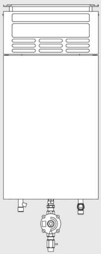
Technical line drawing of a rectangular industrial machine with control panel and piping (no text or symbols)Gas Instantaneous Water Heater
Operation & Installation Manual
Rinnai
Congratulations on the purchase of your Rinnai Gas Instantaneous Water Heater. We trust you will have many years of comfort and enjoyment from your appliance.

BEFORE USING THIS APPLIANCE
Before proceeding with the operation or installation read this manual thoroughly and gain a full understanding of the appliance, to ensure safe and correct use.
This appliance must be installed in accordance with:
• Manufacturer's Installation Instructions
• Current AS/NZS 3500.4 & AS/NZS 5601
- Local Regulations and Municipal Building Codes including local OH&S requirements
This appliance must be installed, maintained and removed by an Authorised Person.
For continued safety of this appliance it must be installed and maintained in accordance with the manufacturer's instructions.

WaterMark
This Appliance complies with AS 3498:2009 AGA LIC. 60089


The Australian Gas Association All Rinnai gas products are A.G.A. certified.
Before Using This Appliance 4
Regulatory Information ....4
Notice to Victorian Consumers 4
Warning About Hot Water 4
Features & Benefits 6
Features and Benefits 6
Operation 7
To Operate 7
Delivery Temperature 7
Water Flow and Temperature Adjustment 8
Freezing Weather 8
Trouble Shooting 9
Fault Finding 9
Maintenance 9
Installation Table of Contents 11
Contacts 24
WARNINGS & IMPORTANT INFORMATION

BEFORE USING THIS APPLIANCE
Before proceeding with the operation or installation read this manual thoroughly and gain a full understanding of the appliance, to ensure safe and correct use.
Always comply with the following precautions to avoid dangerous situations and to ensure optimum performance.
Failure to carefully read and follow all instructions in this manual can result in equipment malfunction, property damage, personal injury and/or death.
DANGER: Indicates an imminently hazardous situation which, if not avoided, will result in personal injury or death.
WARNINGS: Indicates a potentially hazardous situation which, if not avoided, could result in personal injury or death.
CAUTIONS: Indicates a potentially hazardous situation which, if not avoided, could result in minor or moderate injury or damage to the appliance. It may also be used to alert against unsafe practices.

REGULATORY INFORMATION
Your Rinnai gas instantaneous water heater has been certified by the Australian Gas Association. The A.G.A. Certification Number is shown on the data plate.
This appliance must be installed correctly by an appropriately licensed tradesperson.
The installation of gas and water must conform to local regulations, including local OH&S requirements. The installation must also comply with the instructions supplied by Rinnai.
Please keep this instruction booklet in a safe place for future reference.
All dimensions referred to in these instructions are in millimetres, unless otherwise specified.
Notice to Victorian Consumers
This appliance must be installed by a person licensed with the Victorian Building Authority. Only a licensed person will have insurance protecting their workmanship. So make sure you use a licensed person to install this appliance and ask for your Compliance Certificate.
For further information contact the Victorian Building Authority on 1300 815 127.

WARNING ABOUT HOT WATER
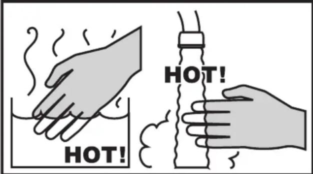
Hot water can cause scalding. Those most at risk are children and disabled, elderly and infirm persons.
Rinnai have water heater models which limit the delivery temperature to 50^ C which significantly reduces the scald hazard. Temperature limiting devices may also be able to be fitted. Contact Rinnai for further information.
ALWAYS test the water temperature before use, such as when filling a bath or basin or entering a shower, to ensure it is suitable for the application and will not cause scald injury.
ALWAYS supervise children whenever they are in the bathroom or near other sources of hot water. Ensure any hot water taps are closed firmly after use.

DANGER BEWARE OF SCALDING HAZARDS
Immediately report any damage or discrepancies to the Supplier of the appliance. This appliance was inspected and tested at the time of manufacture and packaging, and released for transportation without known damage. Upon receipt, inspect the exterior for evidence of rough handling in shipment. Ensure that the appliance is labelled correctly for the gas and electrical supply, and/or other services it is intended to be connected to.
For safety and warranty purposes, appliances that may be damaged or incorrect must not be installed or operated under any circumstances. Installation of damaged or incorrect appliances may contravene local government regulations. Rinnai disclaims any liability or responsibility whatsoever in relation to the installation or operation of damaged or incorrect appliances.

The range of Rinnai gas instantaneous water heaters referred to in this manual are incompatible with solar water heating systems. A dedicated range of solar compatible gas continuous flow water heaters is available from Rinnai.

natural_image
Illustration of hands holding a tube with a question mark above, next to a container with liquid (no text or symbols)Always check water temperature carefully before use. Refer to the "WARNING ABOUT HOT WATER" on page 4 for important safety information.
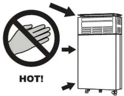
DO NOT touch the unit cover or the flue outlet.
DO NOT insert objects into the flue outlet.
DO NOT spray water directly into the flue outlet.
Keep, trees, shrubs, etc. well clear of the flue outlet.
On colder days steam may discharged from the flue outlet. This condition is normal for high efficiency appliances and does not indicate a fault.
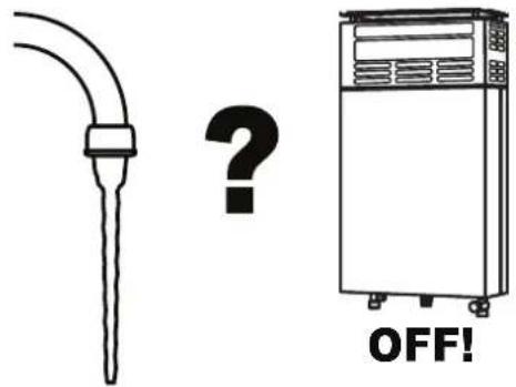
At low water flows, the hot water unit may extinguish without warning. Opening the tap further will restart the heating appliance.

DO NOT Spray aerosols in the vicinity of this appliance while it is in operation.
DO NOT use or store flammable materials in or near this appliance.
DO NOT place articles on or against this appliance.
DO NOT modify this appliance.
DO NOT store pool chemicals near this appliance.
FEATURES AND BENEFITS
FEATURES & BENEFITS
Congratulations on purchasing the Rinnai Gas Instantaneous water heater.
• The appliance is compact, saving both wall and floor space.
- The burner lights automatically when the hot water tap is opened, and goes out when the tap is closed. IGNITION IS ELECTRONIC rather than by pilot light for optimum reliability and minimum running costs. When the hot water tap is closed no gas is used.
- The appliance has a very high gas combustion efficiency minimising gas consumption and operating cost.
• Operating noise level is very low.
Unlike most other instantaneous water heaters, this model is fitted with a battery powered electronic ignition and microprocessor control module offering unique benefits as follows:
- Electronic ignition rather than ignition by pilot light ensures optimum reliability and minimum running costs as no gas is used when the hot water tap is closed.
- The water temperature and gas flow are microprocessor controlled offering superior performance.
- Battery power ensures optimum reliability and eliminates the need for a mains power supply and associated costs.
Unlike most other instantaneous water heaters, this appliance also has a modern state of the art flue design for reliable operation even under high wind conditions.
TO OPERATE
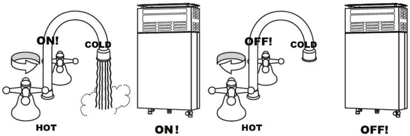
The opening of any hot water tap will automatically start the appliance.
Once water is flowing through the appliance the burner will be ignited by electronic ignition via the electronic ignition and control module.
When the hot water tap is closed and water flow through the appliance has stopped the burner flame will extinguish.
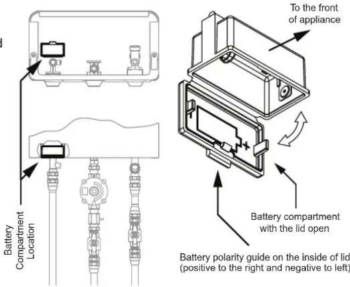
Battery for electronic ignition and control module
A long life 1.5 Volt "D" size battery is supplied with the appliance and should have been fitted by your installer.
If the battery runs flat, replace it with a new 1.5 Volt "D" size battery. Long life batteries are recommended. The battery compartment is located on the left hand side at the bottom of the appliance. Approximate battery life is 6 to 12 months. Actual battery life may be different depending on individual hot water usage patterns.
- Locate the battery compartment and open the hinged lid (opens towards the rear of appliance).
- Remove the expired battery and replace it with a new battery ensuring that the correct polarity is observed, as is shown on the inside of the battery compartment lid.
- Close the battery compartment lid.
DELIVERY TEMPERATURE
The delivery temperature set point programmed into the electronic ignition and control module is 60^ C.
The actual delivery temperature may be lower depending on the prevailing operating conditions, for example, low incoming cold water temperatures and high water flow rates.
WATER FLOW AND TEMPERATURE ADJUSTMENT
Water fixtures with a rated water flow rate of 7.5 litres per minute or higher are recommended.
A water flow adjustment lever is fitted to adjust the maximum water flow from the appliance. Such adjustment may be useful to compensate for seasonal variations in the temperature of the cold water supply.
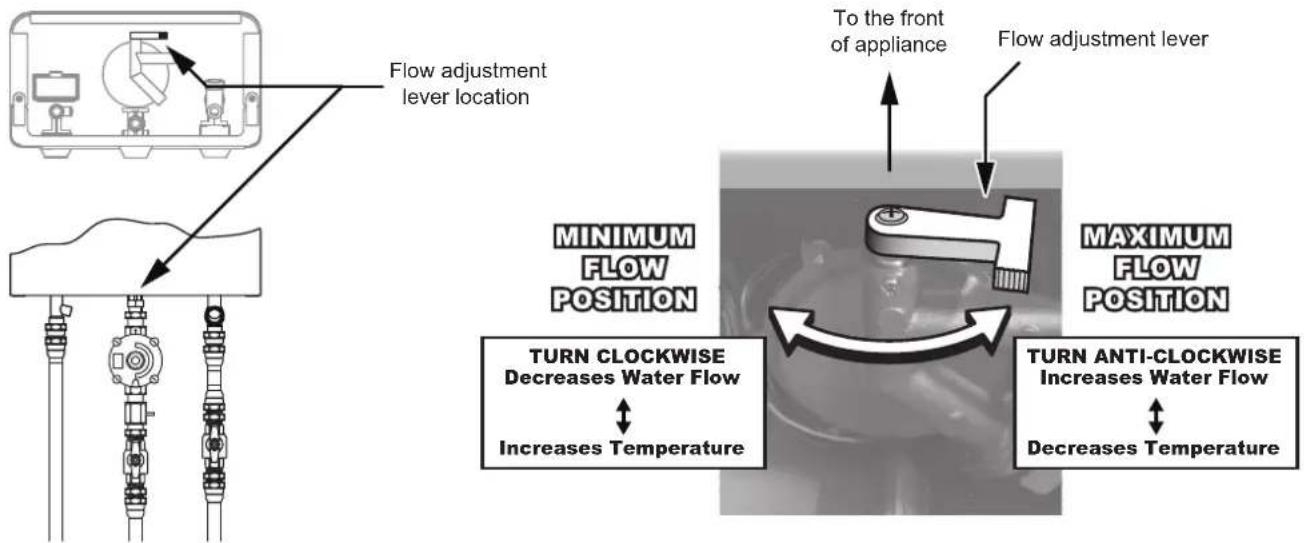
- Turning the water flow adjustment lever towards the left (Clockwise) will decrease the water flow and increase the hot water temperature. This setting is recommended during winter.
- Turning the water flow adjustment lever towards the right (Anti-clockwise) will increase the water flow and decrease the hot water temperature. This setting is recommended during summer.
- If the heated water temperature delivered from an outlet is not hot enough it can normally be increased to the desired temperature by closing the tap a little as this will reduce the water flow rate.
- The appliance has a minimum water flow rate that is required for operation. If the water heater does not activate when opening a tap, the flow rate may be too low. Open the tap a little more to increase the water flow rate.
FREEZING WEATHER

This water heater MUST NOT be installed in areas where the temperature remains below 0^ C for extended periods.
If freezing conditions are expected (drop below 0^ C), turn off water and gas and drain all water from the appliance to prevent damage by expansion of freezing water.
For appliances installed in locations where the temperature falls below 0^ C for short periods, the installation of an Anti Freezing Relief Valve (Exogel or equivalent brand) will minimise the possibility of damage to the appliance. This is not supplied with the water heater.
FAULT FINDING
| Problem Fault Solution | ||
| Burner does not ignite, or is difficult to ignite | No gas supply | Check gas is turned on at water heater and gas meter or cylinder |
| Low battery power Replace battery | ||
| Other Service Call | ||
| Pilot lights but no main burner | Low water pressure Check water pressure | |
| Low battery power Change battery | ||
| Run out of cylinder gas Replace gas cylinder | ||
| Other Service call | ||
| Low water temperature | Low gas pressure | Check gas pressure. To be carried out by an authorised person only |
| Run out of cylinder gas Replace gas cylinder | ||
| Excessive water flow rate | Reduce water flow from heater (Turn water lever clockwise) | |
| Other Service Call | ||
| Low water flow | Low water pressure Check water pressure to appliance | |
| Blocked outlet fixture Check and clean | ||
| Other Service call | ||
| Cuts off when operating | Interrupted gas supply Service call | |
| Run out of cylinder gas supply Replace gas cylinder | ||
| Other Service call | ||
| Smell gas Faulty / loose gas connection | Service call | |
| Water leakage from appliance | Damaged components and connections | Service call |
| Frost damage | Service call | |
| Water leakage from pressure relief valve | Excessive pressure | Check water supply pressure |
| Faulty pressure relief valve | Service call | |
MAINTENANCE
Rinnai has a Service and Spare Parts network with personnel who are fully trained and equipped to give the best service on your appliance. If your appliance requires service, please call our National Help Line. Rinnai recommend that the appliance be serviced by an authorised person every 3 years.
This page is intentionally blank
INSTALLATION TABLE OF CONTENTS
Operation Table of Contents 3
General Installation Information 12
Regulations 12
Applicable Models 12
Unpacking the Appliance 12
Appliance Location 12
Pipe Sizing 12
Water Supply 13
Hot Water Delivery Temperature 13
Appliance Mounting Requirements 13
Appliance Mounting Method 14
Service Connection Points .... 14
Flueing 15
Appliance Flue Terminal 15
Commissioning 16
Testing 16
Commissioning Check List 17
Installation Record 17
Specifications 18
Appliance Dimensions 19
Wiring Diagram 20
Contacts 24

Installation, service and removal MUST BE by an appropriately licensed tradesperson ONLY.
It is the installer's responsibility to ensure all current AS/NZS 5601 requirements are met.
Remove transit protection. Check for damage, if any is found DO NOT install and contact supplier.
REGULATIONS
This appliance must be installed in accordance with:
• Current AS/NZS 3500.4 and AS/NZS 5601
• Rinnai Installation Instructions
- Local regulations and municipal building codes including local OH&S requirements
The Authorised Person performing the installation is responsible for:
- Correct commissioning of the appliance.
- Ensuring the appliance performs to the specifications on the dataplate.
- Demonstrating the operation of the appliance to the customer, including water flow rate adjustment.
- Demonstrating the location of the battery compartment and how to replace the battery.
- Advising the customer of the need for regular servicing (Rinnai recommends servicing every 2 years).
- Handing these instructions to the customer.
APPLICABLE MODELS
These Installation Instructions apply only to the Rinnai gas instantaneous water heater models that are listed on the cover page of this manual.
UNPACKING THE APPLIANCE
Packed with the appliance should be the Operating / Installation Manual, Commissioning check list, Warranty booklet, Gas adaptor with washer, Gas regulator, Regulator inlet pressure testing point, Battery and Heat shield kits. Remove all packaging and protective materials from the appliance and accessories. If any damage is evident or any accessories are missing DO NOT install or operate the appliance. Contact your supplier for advice.
APPLIANCE LOCATION
- This appliance is designed for ‘Outdoor’ Installation only. As such, it MUST BE located in an above ground open air situation with natural ventilation, without stagnant areas, where gas leakage and products of combustion are rapidly dispersed by wind and natural convection.
- This appliance MUST BE mounted on a vertical structure with the water and gas connections on the underside pointing downwards. For appliances installed on elevated structures or under floors specific requirements apply. Refer to AS/NZS 5601 for details.
- This appliance MUST NOT be used as a domestic spa, swimming pool heater or as part of a solar hot water system.
- This appliance MUST BE placed as close as practicable to the most frequently used hot water outlet or outlets to minimise the delay time for hot water delivery.
- All appliances must be installed to ensure access can be gained without hazard or undue difficulty for inspection, repair, renewal or operational purposes. Sufficient clearances shall allow access to, and removal of, all serviceable components.
- Appliances should not be mounted higher than 2.5 metres above the ground or floor level unless the customer can arrange permanent and safe access or can provide another means of access, for example, by means of scissor or boom lifts acceptable to local authorities.
PIPE SIZING
- See Table 1 (Specification table) for appliance gas consumption. If the gas pipe sizing is insufficient the customer will not get the full performance benefit. Gas pipe sizing must consider the gas input to this appliance as well as all the other gas appliances in the premises. The gas meter and regulator must be specified for this gas rate. An approved sizing chart such as the one in AS/NZS 5601 should be used.
- Water pipe sizing and layout should be performed in accordance with AS/NZS 3500.4. All hot water pipework should be insulated to optimise performance and energy efficiency.
WATER SUPPLY
See "Table 1. Appliance Specifications" on page 18, for applicable water pressures. Approved pressure limiting valves may be required if the 'Maximum' rated water supply pressures in Table 1 are exceeded. To achieve the rated flow, the 'Minimum' water supply pressures in Table 1 must be supplied. The water heaters will operate at lower pressures but will not achieve the rated flow.
Water chemistry and impurity limits are detailed in the separate Warranty booklet. Most metropolitan water supplies fall within the requirements. If you are unsure about your local water quality, contact your water authority. If sludge or foreign matter is present in the water supply, a suitable filter or strainer should be incorporated in the water supply to the water heater.
HOT WATER DELIVERY TEMPERATURE
- The delivery temperature set point programmed into the electronic ignition and control module is 60^ C. The actual delivery temperature may be lower depending on the prevailing operating conditions, for example, low incoming cold water temperature and high water flow rate.
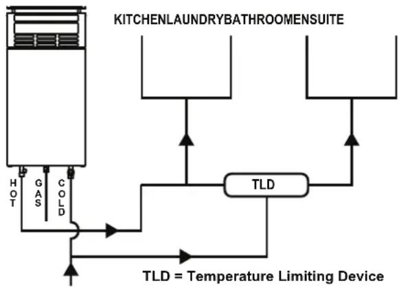
- Local regulations and/or the requirements of AS/NZS 3500.4 must be considered regarding the temperature limitations of hot water supplied to areas used primarily for personal hygiene. The temperature of water to these areas may be limited to 50°C or less. This can be achieved by the use of a Temperature Limiting Device (TLD). Installation with a TLD is to be in accordance with the diagram right.
flowchart
graph TD
    A["Hot Water Tank"] --> B["Gas"]
    B --> C["COLD"]
    C --> D["TLD"]
    D --> E["TLD = Temperature Limiting Device"]
    E --> F["Output"]
    G["KITCHENLAUNDRYBATHROOMENSUITE"] --> H["Output"]
    H --> I["TLD"]
    I --> J["TLD"]
    J --> K["Output"]
APPLIANCE MOUNTING REQUIREMENTS
- See "Table 1. Appliance Specifications" on page 18 for individual appliance weights. The wall or structure on which the appliance is to be mounted must be capable of supporting these weights and that of the associated pipe-work.
- Ensure that suitable fixing screws or bolts are used to secure the unit to the wall; in accordance with AS/NZS 5601.Wooden Plugs MUST NOT be used.
- The appliance can be mounted directly against a wall or structure, however it is MANDATORY that the provided heat shield is fitted.

To meet the temperature hazard protection requirements of AS/NZS 5601, fitting of the provided heat shield is MANDATORY.
Refer to "Appliance Mounting Method" on page 14 for instructions of how to mount both the water heater and the provided heat shield.
APPLIANCE MOUNTING METHOD
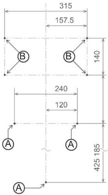
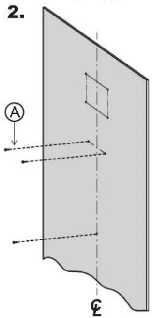
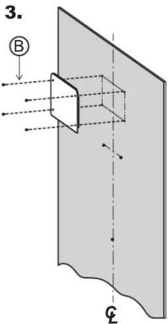
- After determining the desired location for the water heater, use the dimensions in the drawing right to measure and mark off the positions of the 3 appliance mounting points Ⓐ and the 4 heat shield mounting points Ⓑ.
- Install 3 suitable screws or bolts at the 3 appliance mounting points Ⓐ.

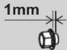
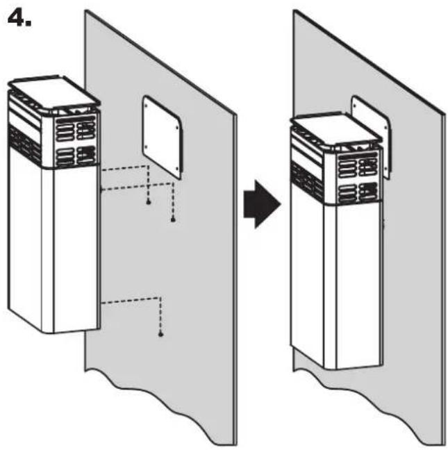
Ensure to leave at least a 1mm gap between the inner face of the fixing and the wall. This gap is necessary as it will facilitate the correct mounting of the water heater in step 4.
- Using suitable fixings secure the heat shield flush onto the wall at the 4 heat shield mounting points Ⓑ.

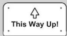
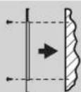
The heat shield is to be mounted with the more rounded corners facing upwards and with the folded tabs facing the walls surface.
- Using the keyed mounts points, hang the water heater onto the 3 appliance mounting fixings installed in step 2. Ensuring that all 3 mounting points are securely engaged.
SERVICE CONNECTION POINTS

See Table 1, (Specification table) for individual appliance connection / fitting dimensions. These dimensions are NOT an indication of the pipe sizes required.
- An approved full flow isolation valve and disconnection union MUST be fitted to the cold water inlet.
- A non return valve is not required unless required by local regulations. Isolation valves MUST NOT be fitted directly to the appliance.
- Purge gas and cold water supply lines to remove air and swarf before final connection of the appliance. Swarf in either the gas or water supplies may cause damage or malfunction. These are not covered by warranty.
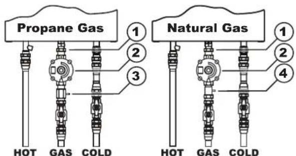
① 12 ' Gas Adaptor with washer (supplied)
② Gas Regulator (supplied)
③ 12 ' to 12 ' Regulator inlet pressure test point (supplied)
④ 34 to 12 Regulator inlet pressure test point (supplied)
APPLIANCE FLUE TERMINAL
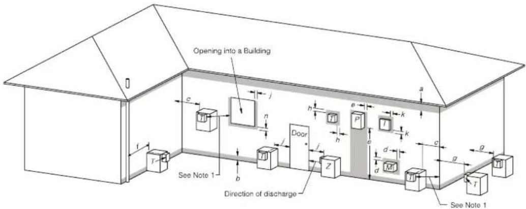
T = Flue terminal Fan assisted flue appliance only Gas meter Electricity meter or fuse box Mechanical air inlet
Shading indicates prohibited areas for flue terminals
| Ref.ef. | Min clearances mm | |
| Natural draught | ||
| a | Below eaves, balconies and other projections: | |
| For appliances up to 50 MJ/h input 300 | ||
| For appliances over 50 MJ/h input 500 | ||
| b From the ground, above a balcony or other surface * 300 | ||
| c From a return wall or external corner * 500 | ||
| d | From a gas meter (M) (see Note 5)(see Clause 5.11.5.9 for vent terminal location of regulator)(see Table 6.7 for New Zealand requirements) | 1 000 |
| e From an electricity meter or fuse box (P) ^ (see Note 5) | 500 | |
| f From a drain pipe or soil pipe | 150 | |
| g | Horizontally from any building structure * or obstruction facing a terminal | 500 |
| h From any other flue terminal, cowl, or combustion air intake * | 500 | |
| j | Horizontally from an openable window, door, non-mechanical air inlet, or any other opening into a building with the exception of sub-floor ventilation: | |
| Appliances up to 150 MJ/h input* | 500 | |
| Appliances over 150 MJ/h input up to 200 MJ/h input* | 1 500 | |
| Appliances over 200 MJ/h input up to 250 MJ/h input* | 1 500 | |
| Appliances over 250 MJ/h input* | 1 500 | |
| All fan-assisted appliances, in the direction of discharge | — | |
| k From a mechanical air inlet, including a spa blower | 1 500 | |
| n | Vertically below an openable window, non-mechanical air inlet, or any other opening into a building with the exception of sub-floor ventilation: | |
| For space heaters up to 50 MJ/h input | 150 | |
| For other appliances up to 50 MJ/h input | 500 | |
| For appliances over 50 MJ/h input and up to 150 MJ/h input | 1 000 | |
| For appliances over 150 MJ/h input | 1 500 | |
* Unless appliance is certified for closer installation.
^ Prohibited area below electricity meter or fuse box extends to ground level.
NOTES:
1 Where dimensions c, j or k cannot be achieved an equivalent horizontal distance measured diagonally from the nearest discharge point of the terminal to the opening may be deemed by the Technical Regulator to comply.
2 See Clause 6.9.4 for restrictions on a flue terminal under a covered area.
3 See Figure J3 for minimum clearances required from a flue terminal to an LP Gas cylinder. A flue terminal is considered to be a source of ignition.
4 For minimum clearances not addressed above acceptance should be obtained from the Technical Regulator.
5 Minimum clearances d and e also apply to any combustion air intake openings of appliances.
FIGURE 6.2 (in part) LOCATION OF FLUE TERMINALS OF BALANCED FLUE, ROOM-SEALED, FAN-ASSISTED OR OUTDOOR APPLIANCES
COMMISSIONING
TESTING
- Before final connection of the water heater purge gas, hot water and cold water supply lines. Swarf either the gas or water supplies may cause damage or malfunction which is not covered by warranty.
- See Table 1 for connection size, water and gas pressure specifications.
- Turn on gas and cold water supplies.
- Test for water leaks and gas escapes.
- Isolate gas and water supplies. Remove test point screw located on the regulator inlet pressure test point and attach pressure gauge Fig. 1.
- Turn on gas and open hot water taps fully. Ensure water flow lever is in the maximum flow position. Refer to "Water Flow and Temperature Adjustment" on page 8.
- With all gas appliances in operation at maximum gas rate, the pressure at the regulator inlet pressure test point should read between 1.13 - 3.0 kPa on Natural Gas. On LPG the pressure should be 2.75 - 3.0 kPa. If the pressure is lower, the gas supply is inadequate and the appliance will not operate to specification. It is the Installers responsibility to check the gas meter, service regulator and pipe work for correct operation/sizing and rectify as required.

If the sparker activates but the pilot and main burner do not light, then the gas pressure at the outlet of the regulator is too low.
Increase the pressure at the outlet of the regulator by slowly turning the adjustment screw clockwise until a suitable pilot flame and main burner flame are established.
- Replace the test point screw on the regulator inlet pressure test point.
- Isolate gas and water supplies. Remove the test point screw located to the burner pressure test point on the left hand side of burner manifold as shown right and attach pressure gauge Fig. 2
- Turn on the gas and open hot water taps fully. Ensure the water flow lever is in the maximum flow position.
- For burner test point pressures refer to the appliance data plate. If the pressures are different adjust the inlet gas regulator to achieve the required burner test point pressures.
- Close all hot water taps including the shower.
- Inspect and clean the strainer located on the cold water inlet connection. This procedure may need to be repeated to ensure the strainer remains clear, especially on new installations Fig. 3.
- After testing is completed, explain to the householder the functions and operation of the water heater.
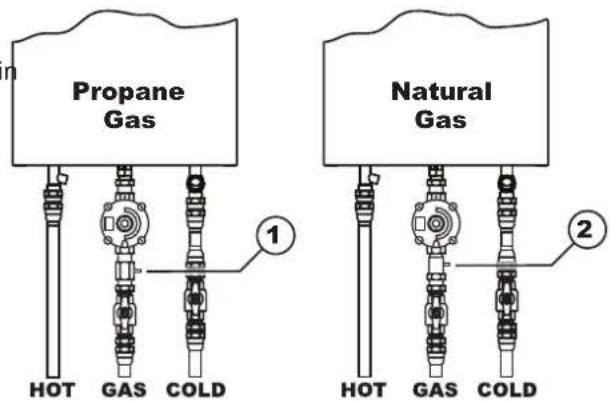
① Propane gas regulator inlet pressure test point screw
② Natural gas regulator inlet pressure test point screw
Fig. 1.
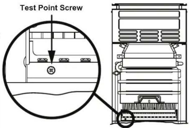
Fig. 2.
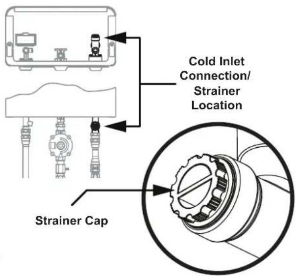
Fig. 3.
COMMISSIONING CHECK LIST
A commissioning check list is provided on the appliance front cover to enable the installer to step through the correct commissioning procedure when installing a Rinnai water heater.
The check list can also assist the installer to identify potential installation errors that may prevent the appliance from operating correctly.
INSTALLATION RECORD
The Installation Record is a reference for the end user, help line staff and service technicians. Ensuring that this information is available here will be helpful in the event that a service enquiry is required.
Installer Details
Installation Company Name: ____
Address:
Telephone / Mobile Phone: ____ / ____
Email:
Certificate of Compliance / Certification No.: ____
Authorised Persons - Licence No.: ____
Installers Name: ____
Installers Signature: ____
Installation Date: ____
System Details
Water Heater - Model Number * : ____
Water Heater - Serial Number*: ____
* This information will need to be copied from the data plate, located on the left hand side of appliance.
Installation Address: ____
SPECIFICATIONS
Table 1. Appliance Specifications
| Model | Water Supply kPa | Weight kg | Fittings | ||||
| Minimum Inlet Water Pressure For 10L/min. | Minimum Inlet Water Pressure For Operation | Maximum Inlet Water Pressure | Hot & Cold Water | Natural Gas Propane Gas | |||
| FM10 120 40 | 1000 14 | R 1/2” BSP Male | R 1/2” BSP Female | R 1/2” BSP Male | |||
| Model Gas Type | Inlet Gas Pressure kPa | Burner TPP kPa | Nominate Gas Consumption MJ/h | Heating Capacity at 25°C rise | |
| FM10NA NG | 1.13 0.69 76.2 | 10 L/min | |||
| FM10LA Propane | 2.75 2.38 76.0 | ||||
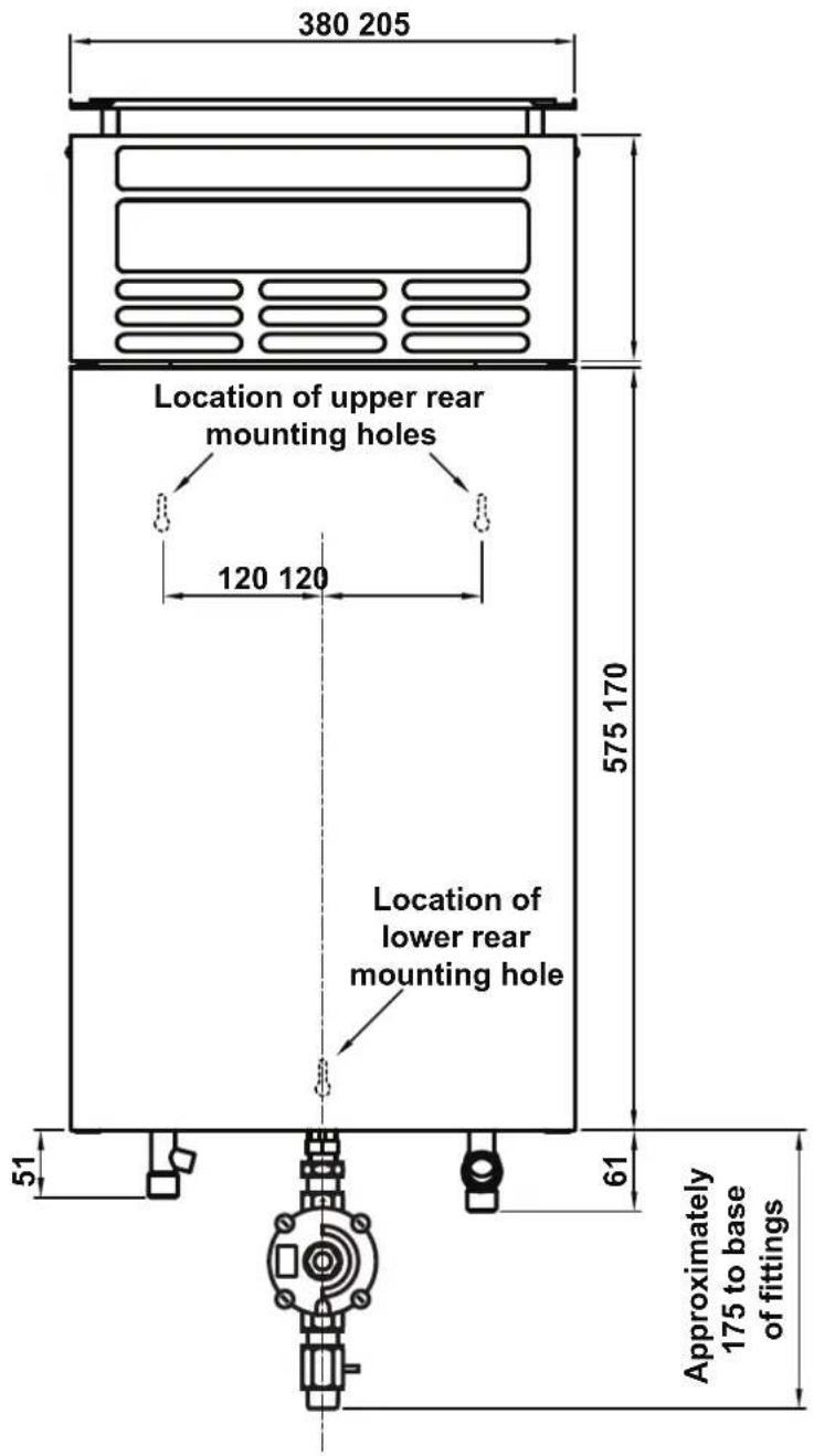
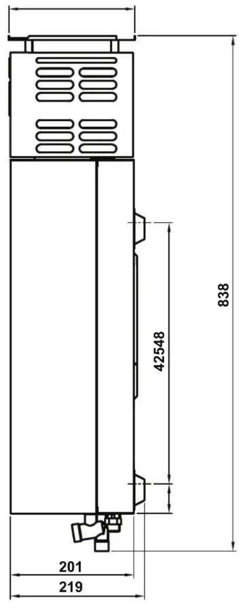
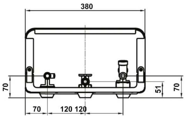
Figure 4. Dimensions
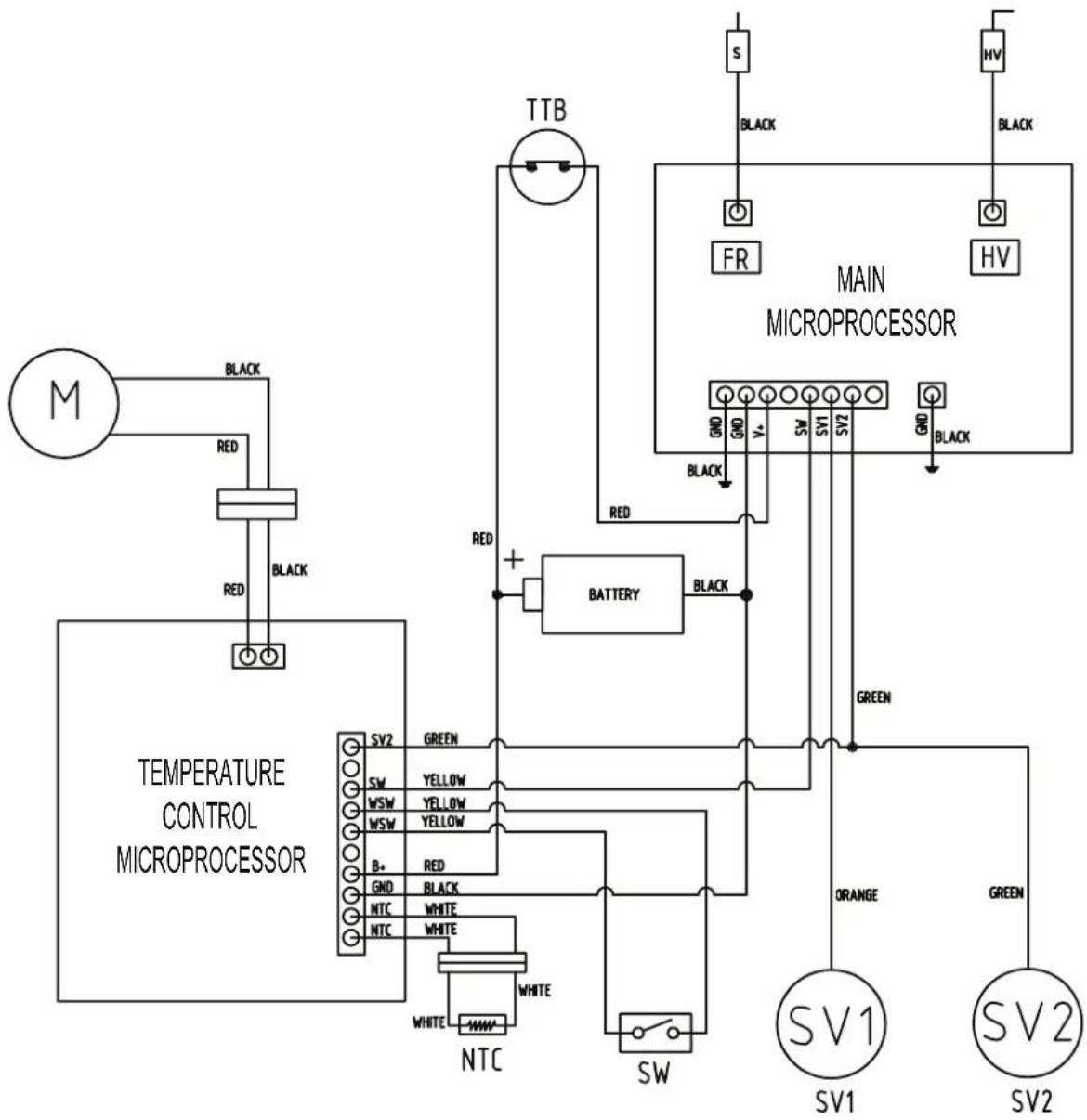
flowchart
graph TD
    A["TEMPERATURE CONTROL MICROPROCESSOR"] --> B["MT"]
    B --> C["RED"]
    C --> D["BLACK"]
    D --> E["RR"]
    E --> F["TTB"]
    F --> G["MAIN MICROPROCESSOR"]
    G --> H["SW1"]
    G --> I["SW2"]
    H --> J["ORANGE"]
    I --> K["GREEN"]
    J --> L["SW"]
    K --> M["SW1"]
    L --> N["Orange"]
    M --> O["Green"]
    N --> P["Green"]
    O --> Q["Black"]
    P --> R["Black"]
    Q --> S["Black"]
    R --> T["BATTERY"]
    T --> U["BACK"]
    U --> V["Black"]
    V --> W["Black"]
    W --> X["Black"]
    X --> Y["Black"]
    Y --> Z["Black"]
    Z --> AA["Black"]
    AA --> AB["Black"]
    AB --> AC["Black"]
    AC --> AD["Black"]
    AD --> AE["Black"]
| SV1 | Solenoid Valve 1 |
| SV2 | Solenoid Valve 2 |
| HV | High Voltage Lead (Ignition) |
| FR | Flame Rod |
| TTB | Temperature Overheat Switch (Self-resetting) |
| M | Modulation Motor |
| NTC | Thermistor (Heated water outlet temperature) |
| SW | Micro-switch |
Figure 5. Dimensions
NOTES
Rinnai Australia Pty Ltd
ABN 74 005 138 769 | AU24752
100 Atlantic Drive, Keysborough, Victoria 3173
P.O. Box 460, Braeside, Victoria 3195
Tel: (03) 92716625
Fax: (03) 92716622
National Help Line
Tel: 1300 555 545* Fax: 1300 555 655
Monday to Friday, 8.00 am to 5.00 pm EST.
After Hours Hot Water Service Line
Tel: 1800 000 340*
*Cost of a local call higher from mobile or public phones.
For further information visit www.rinnai.com.au or email enquiry@rinnai.com.au
Rinnai has a Service and Spare Parts network with personnel who are fully trained and equipped to give the best service on your Rinnai appliance. If your appliance requires service, please call our National Help Line. Rinnai recommends that this appliance be serviced every 3 years.
With our policy of continuous improvement, we reserve the right to change, or discontinue at any time, specifications or designs without notice.
- Gas Instantaneous Water Heater
- Operation & Installation Manual
- BEFORE USING THIS APPLIANCE
- Features and Benefits 6
- Operation 7
- Trouble Shooting 9
- Installation Table of Contents 11
- Contacts 24
- WARNINGS & IMPORTANT INFORMATION
- REGULATORY INFORMATION
- Notice to Victorian Consumers
- WARNING ABOUT HOT WATER
- DANGER BEWARE OF SCALDING HAZARDS
- FEATURES AND BENEFITS
- FEATURES & BENEFITS
- TO OPERATE
- Battery for electronic ignition and control module
- DELIVERY TEMPERATURE
- WATER FLOW AND TEMPERATURE ADJUSTMENT
- FREEZING WEATHER
- MAINTENANCE
- INSTALLATION TABLE OF CONTENTS
- Operation Table of Contents 3
- General Installation Information 12
- Flueing 15
- Commissioning 16
- Specifications 18
- Appliance Dimensions 19
- Wiring Diagram 20
- REGULATIONS
- APPLICABLE MODELS
- UNPACKING THE APPLIANCE
- APPLIANCE LOCATION
- PIPE SIZING
- WATER SUPPLY
- HOT WATER DELIVERY TEMPERATURE
- APPLIANCE MOUNTING REQUIREMENTS
- APPLIANCE MOUNTING METHOD
- SERVICE CONNECTION POINTS
- APPLIANCE FLUE TERMINAL
- NOTES:
- COMMISSIONING
- TESTING
- COMMISSIONING CHECK LIST
- INSTALLATION RECORD
- Installer Details
- System Details
- SPECIFICATIONS
- NOTES
- Rinnai Australia Pty Ltd
Brand : Rinnai
Model : FM10LA
Category : Water heater