
Decor 1SC v2 - Loudspeaker Paradigm - Free user manual and instructions
Find the device manual for free Decor 1SC v2 Paradigm in PDF.


| Product Type | Soundbar Speaker |
| Model | Decor 1SC v2 |
| Brand | Paradigm |
| Speaker Configuration | 1SC (Single Soundbar with Integrated Center Channel) |
| Mounting Options | TV-mounted (VESA) or Wall-mounted |
| Compatible TV Sizes (Wall Mount) | 43" – 64.9" (single bracket) and 65" – 100" (dual brackets) |
| VESA Compatibility | Standard VESA mounting points (M6 or M8 screws included) |
| Installation Hardware Included | KIT0108 mounting kit with rails, brackets, spacers, screws, Torx wrenches |
| Grille Options | Removable cloth grille (optional) |
| Installation Difficulty | Moderate – requires 2 persons for safe installation |
| Safety Notes | Do not lift by TV edge; support both TV and speaker when hanging; use appropriate wall anchors |
| Maintenance | Clean with dry, lint-free cloth; do not use abrasive cleaners |
| Warranty | Refer to manufacturer documentation |
Frequently Asked Questions - Decor 1SC v2 Paradigm
User questions about Decor 1SC v2 Paradigm
0 question about this device. Answer the ones you know or ask your own.
Ask a new question about this device
Download the instructions for your Loudspeaker in PDF format for free! Find your manual Decor 1SC v2 - Paradigm and take your electronic device back in hand. On this page are published all the documents necessary for the use of your device. Decor 1SC v2 by Paradigm.
USER MANUAL Decor 1SC v2 Paradigm
natural_image
Vertical arrangement of five identical circular speaker or speaker units with mounting holes (no text or symbols)
natural_image
Three identical circular speaker or antenna components arranged vertically (no text or symbols visible)
natural_image
Pure diagram of three circular speaker or speaker units arranged vertically (no text or symbols)
natural_image
Pure diagram of four identical circular speaker units arranged vertically (no text or symbols)
natural_image
Vertical arrangement of five identical circular speaker or speaker units with mounting holes, no text or symbols present.TABLE OF CONTENTS
1S/1C/1SC Speaker Installation onto TV.... 3
Preparing Your Décor Soundbar For Installation....3
Preparing Your TV For Speaker Installation....3
Grille Fit 4
Flush Fit....4
1S/1C/1SC Components List....5
2S/2SC Speaker Installation onto TV.... 11
Preparing Your Décor Soundbar For Installation....12
Preparing Your TV For Speaker Installation....12
Grille Fit 13
Flush Fit....13
2S/2SC Components List....14
3SC Speaker Installation onto TV 20
Preparing Your Décor Soundbar For Installation....21
Preparing Your TV For Speaker Installation....21
Grille Fit 22
Flush Fit....22
1S/1C/1SC Components List....23
2S/2SC Components List....24
1S/1C/1SC Wall Mount Installation (43"-64.9" Length Models) ...... 35
1S/1C/1SC Wall Mount Installation (65"-100" Length Models) ...... 36
2S/2C Wall Mount Installation (All Models) 38

Wall mount your speakers securely enough that they cannot fall and cause personal injury or damage to property.

Paradigm DOES NOT supply hardware for mounting speakers to the wall. Always use screws appropriate for wall type and weight of speakers.
NON LIABILITY: We are aware that the mounting assemblies provided for speakers in this manual could be used for purposes and in ways other than those for which they were intended. The manufacturer, distributor, retailer and their respective agents cannot be held responsible or liable for injuries or property damage—direct, indirect or consequential—arising from the use of or inability to use these products safely and properly. Every effort has been made to provide accurate, error-free installation instructions. Paradigm Electronics Inc. disclaims liability for difficulties that may arise from the misinterpretation of information contained in these instructions.

An Important Note About TV Mounting Bracket:
Ensure the TV mounting bracket, attached to the wall, will accommodate the extra weight of the Décor speakers and Décor Mounting Rails BEFORE attaching to wall. If unsure, consult dealer or TV mount manufacturer.

natural_image
Red icon showing two human figures with a warning triangle (no text or symbols)CAUTION: 2 PERSON INSTALLATION
1S/1C/1SC SPEAKER INSTALLATION ONTO TV
Applies to ALL 1C/1S/1SC configurations and lengths.
Parts required:
1x Soundbar
1x Cloth Grille (optional)
1x KIT0108

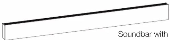
Soundbar with
Cloth Grille
and, one of the following kits:
1x KIT0104 (S)
1x KIT0105 (M)
1x KIT0106 (L)
PREPARING YOUR DÉCOR SOUNDBAR FOR INSTALLATION
The best way to ensure a smooth assembly is to mount your new soundbar to the TV while they're on the floor. First, you should ensure the floor is clear of any debris that may damage your TV or Soundbar. We recommend using a thick blanket to prevent any scratches or direct contact with the floor.
PREPARING YOUR TV FOR SPEAKER INSTALLATION
Place your TV face down on the ground and ensure adequate space to maneuver around during installation.

BACK
GRILLE FIT
If you ordered a Cloth Grille, please remove the grille(s) from its packaging and place it on your Décor Soundbar now. This will ensure the front faces of the TV and soundbar are flush with one another. In addition, if you ordered a contour grille, please ensure that it is aligned with its corresponding TV contour.

FLUSH FIT
Position your new Décor soundbar face down in its desired position relative to your television. When face down, please ensure the mounting channel is always closest to the TV.

natural_image
Technical diagram showing a square frame with mounting holes and a rectangular panel labeled 'Back' (no text or symbols within the diagram itself)Extrusion Brackets in the Mounting Channel.

natural_image
Simple line drawing of a circular container with internal compartments and a small inset image (no text or symbols)1S/1C/1SC COMPONENTS LIST
1x Soundbar

natural_image
Pure electrical circuit lines without any symbols1x KIT0104 or KIT0105 or KIT0106

natural_image
Simple line drawing of a rectangular object with horizontal lines and rounded ends, labeled (A) 2x at the top (no text or symbols on the object itself)(A) Fixed Rail length will differ between KIT0104 / KIT0105 / KIT0106
12x 3 Plastic Spacers

2x Threaded Shafts (long)
2x Threaded Shafts (short)
4x Anchor Screws

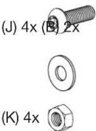
2x Sliding Rail Assemblies
1x KIT0108
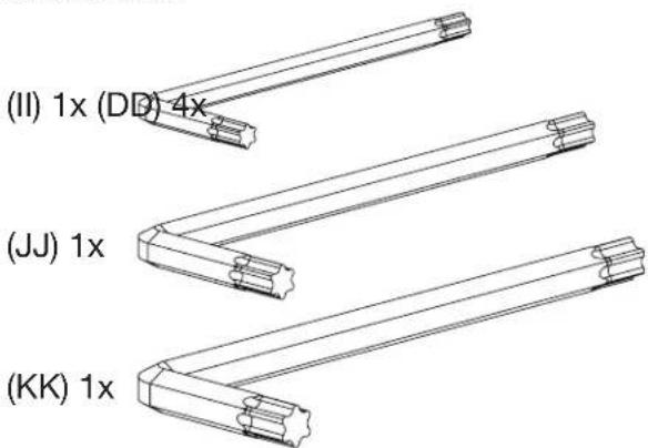
3x Torx Wrenches
4x Rail Spacers

VESA Screws M6
KIT0108

VESA Screws M8
KIT0108

1
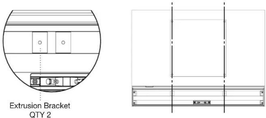
Remove the tape securing both Extrusion Brackets to the soundbar.
Slide the two Extrusion brackets (located on the mounting channel) to roughly align with the VESA mounting points on your TV.
2
To protect the TV from the Fixed Rails, position the Plastic Spacers over the four VESA mounting inserts.
- By default, please start with (I) 10mm spacers (these are the thickest).
- Position the two static rails (A) over the plastic spacers.
• These rails should be vertically oriented and fit within the profile of the TV.
• They should also be sitting level with or higher than your soundbar.
Note: Now is an excellent time to determine if your static rails require additional spacers to ensure they sit higher than your Décor Soundbar. Use the spacers (G, H, I) provided in your Mounting KIT to adequately raise the level of your rails.
Feel free to use the included VESA screws (KIT0108 - A, B, C, D, E, F) throughout the installation process to keep all mounting components aligned with the VESA mounting points.

3
Fasten the length-appropriate Threaded Shafts (D, E - QTY 2x) onto the two extrusion brackets. Do not tighten them all the way, as some adjustments may be required later.

natural_image
Technical diagram showing mechanical assembly with cross-sectional view and pin alignment instructions (no text or symbols)4
Putting the Sliding Rail Assembly together.
The mounting configuration you received requires constructing two Sliding Rail assemblies.
For this you will need:
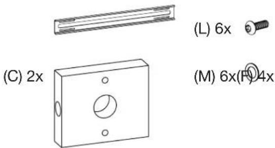
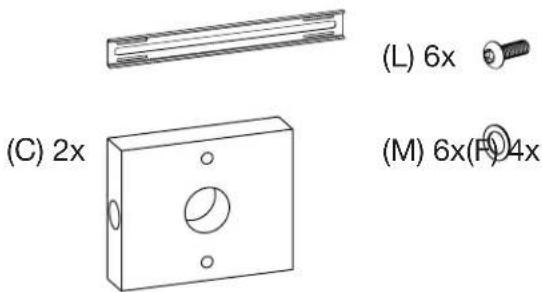
2x Sliding Rails (B)
2x Sliding Rail Brackets (C)
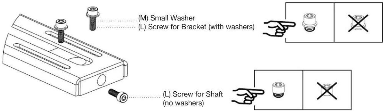
4x Small Washer (M)
6x Shaft / Bracket Screws (L)
Constructing the Sliding Rail Assembly:
a. Each of the Sliding Rail Brackets (QTY 2x) require 2x Shaft / Bracket Screws to fasten onto the Sliding Rails, and
b. 2x Shaft / Bracket Screws to secure the Threaded Shaft.
Place the fastened bracket onto its corresponding section of the Sliding Rail (show double-slotted section of rail). PLEASE DO NOT TIGHTEN THE SCREWS ALL THE WAY.
5
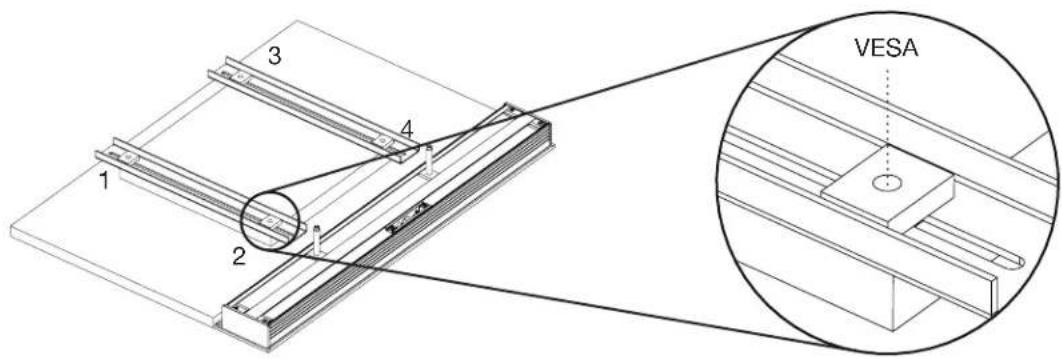
Spacers (KIT0108-H)
Before you proceed any further, please take a moment to ensure that each Fixed Rail has two metal spacers over each of their VESA mounting points. This is to ensure that when tightening the VESA screws, the rail compression does not exceed their mechanical thresholds.
6
Once assembled, position each Sliding Rail assembly over the previously positioned Static Rails (and their spacers), with the bracket side pointed downwards (show).

natural_image
Technical line drawing of a structural assembly with multiple horizontal supports and a central support (no text or symbols)Slide the assembled Sliding Rails over the Threaded Shaft. The Sliding Rails should have one end through the Threaded Shaft and the other resting on the Static Rails.

natural_image
Technical line drawings of two mechanical components with no visible text or symbols7
Tighten the threaded shafts and their corresponding screws on the sliding brackets.

8
Securing the rail position.
You will need:
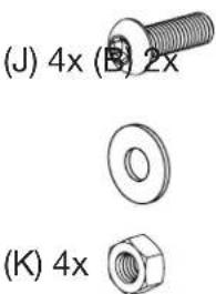
2x Anchor Screws (J)
2x Washers (F)
2x Nuts (K)
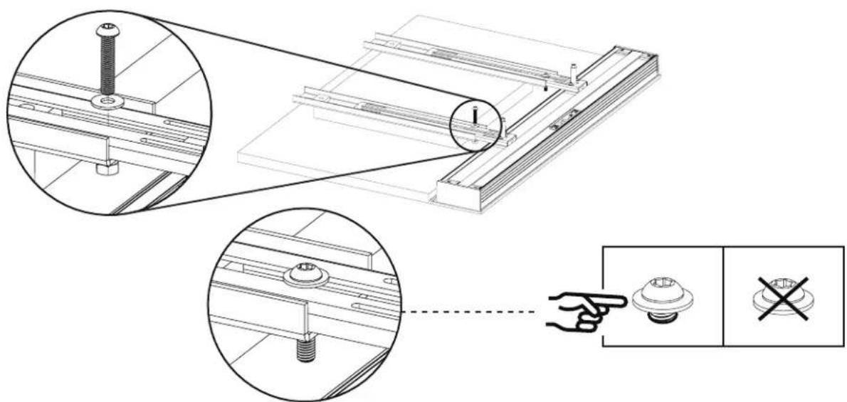
Anchor Screw Installation
At this point, the positioning of ALL Rails will not change, and the positioning will be fixed by the Anchor Screws. To install the Anchor Screw, insert the screw from the underside of the Rail below the bottom-most VESA mounting points and thread the nut/washer combo onto the screw from the opposite side. PLEASE DO NOT TIGHT-EN THE SCREWS ALL THE WAY.
9
For this step, you will need:
You will need:
1x Third-party TV Bracket
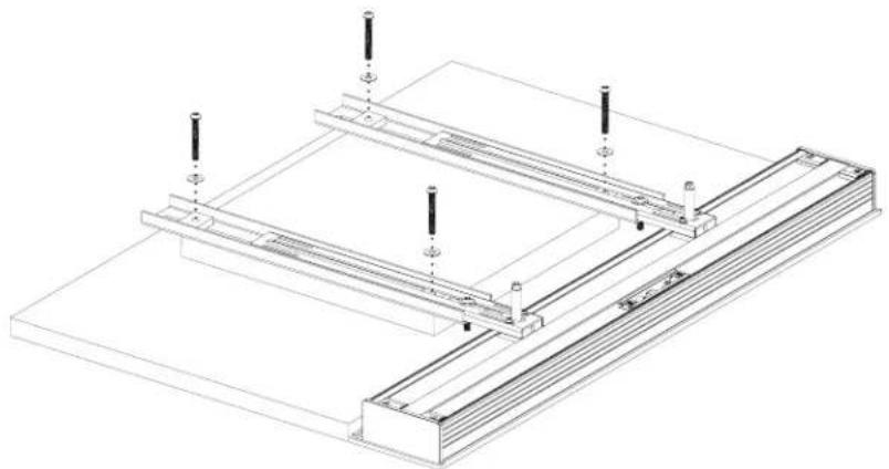
4x Provided VESA Mounting Screws (AA, BB, CC, DD, EE, FF)
Remove the untightened VESA Mounting Screws (QTY 4x) that have been aligning the assembly so far.
natural_image
Technical line drawing of a structural assembly with mounting brackets and support posts (no text or symbols)With the Anchor Screws in place, please proceed to place your third-party TV Bracket over the assemblies.
With the TV Bracket in position, re-insert the VESA Mounting Screws you have been using to align the assembly and begin tightening them with the provided Torx Keys.

natural_image
Technical line drawings of two structural panel assemblies with mounting brackets and support posts (no text or symbols)
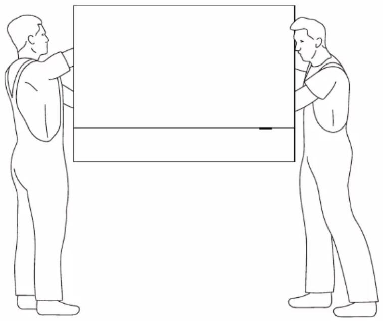
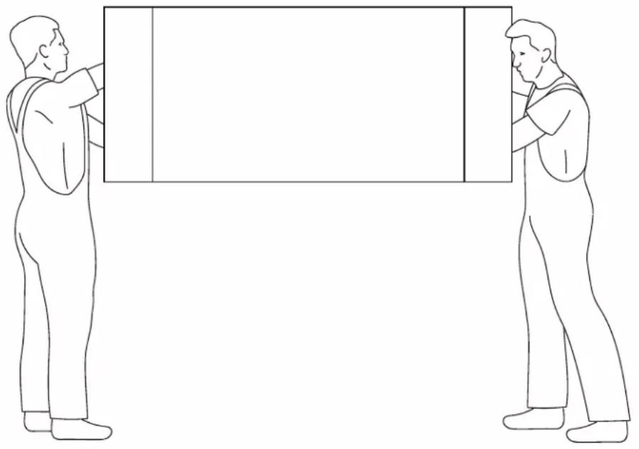
CAUTION: THIS IS A TWO PERSON PROCEDURE. TWO PEOPLE ARE NEEDED TO CARRY OUT THE INSTRUCTIONS OUTLINED BELOW. BE CAREFUL NOT TO DAMAGE TV AND SPEAKER DRIVERS DURING BRACKET INSTALLATION.

CAUTION: CAREFULLY LIFT BY RAILS. DO NOT LIFT BY TV EDGE. Support entire bracket assembly and place onto TV Mount on wall (purchased separately). Follow TV Mounting instructions. WHEN HANGING THE TV, SUPPORT BOTH THE TV AND THE ATTACHED SPEAKERS.
Once all screws have been adequately tightened, lift your TV and Soundbar and mount the assembly onto your third-party wall bracket.
natural_image
Two men in suits standing beside a blank rectangular object, no text or symbols present2S/2SC INSTALLATION INSTRUCTIONS ONTO TV
Applies to ALL 2S and 2SC speaker configurations and lengths.
Parts required:
2x Soundbar
2x Cloth Grille (optional)
1x KIT0108

Soundbar with
Cloth Grille
and one of the following kits:
1x KIT0102 (S)
1x KIT0107 (M)
1x KIT0103 (L)
PREPARING YOUR DÉCOR SOUNDBAR FOR INSTALLATION
The best way to ensure a smooth assembly is to mount your new soundbar to the TV while they're on the floor. First, you should ensure that the floor is clear of any debris that may damage your TV or Soundbar. We recommend using a thick blanket to prevent any scratches or direct contact with the floor.
PREPARING YOUR TV FOR SPEAKER INSTALLATION
Place your TV face down on the ground and ensure adequate space to maneuver around during installation.

BACK
GRILLE FIT
If you ordered a Cloth Grille, please remove the grille(s) from its packaging and place it on your Décor Soundbar now. This will ensure the front faces of the TV and soundbars are flush with one another.
| TV |
Front
FLUSH FIT
Position your new Décor soundbars face down in the desired positions relative to your television. When face down, please ensure the mounting channel is always closest to the TV. The soundbars should be installed flush against the TV, and the top and bottom sides should be aligned with the TV's top and bottom sides.
Note: 2SC Soundbars must also be oriented in the correct "L" (left) and "R" (right) orientations.

2S/2SC COMPONENTS LIST
2x Soundbar
natural_image
Pure electrical circuit lines without any symbols- 2 MDF Grilles (if option selection)
- 4x Extrusion Brackets
1x KIT0102 or KIT0107 or KIT0103
(A) 2x

(A) Fixed Rail length will differ between KIT0102 (S) / KIT0107 (M) / KIT0103 (L)
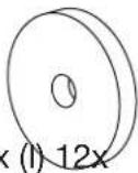
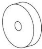
12x 3 Plastic Spacers
(G) 12x

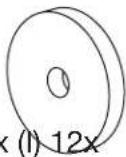
(H) 12x (I) 12x
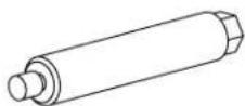
2x Threaded Shafts (long)
2x Threaded Shafts (short)
4x Anchor Screws
(E) 4x

(J) 8x

(D) 4x

(K) 8x


2x Sliding Rail Assemblies

(L) 12x

(C) 4x

(M) 12x(F)8x
1x KIT0108
3x Torx Wrenches
(II) 1x

VESA Screws M6
KIT0108
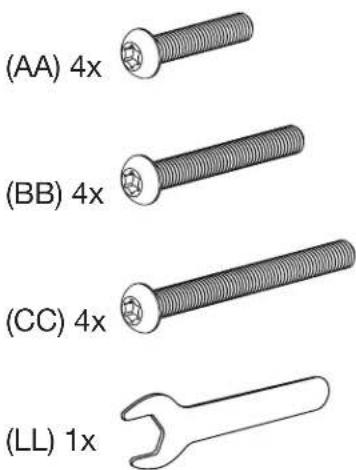
(AA) 4x
VESA Screws M8
KIT0108
(BB) 4 ×

(EE) 4x

(CC) 4x

(FF) 4x

4x Rail Spacers
(HH) 4x

(LL) 1x

1
Remove the tape securing both Extrusion Brackets to the soundbar.
Slide the two extrusion brackets (located on the mounting channel) to roughly align with the VESA mounting points on your TV.


natural_image
Pure architectural or structural line drawing with vertical and horizontal panels, no text or symbols present2
To protect the TV from the fixed rails, position QTY 4 Plastic spacers over the four VESA mounting inserts.
- By default, please start with (I) 10mm spacers (these are the thickest).
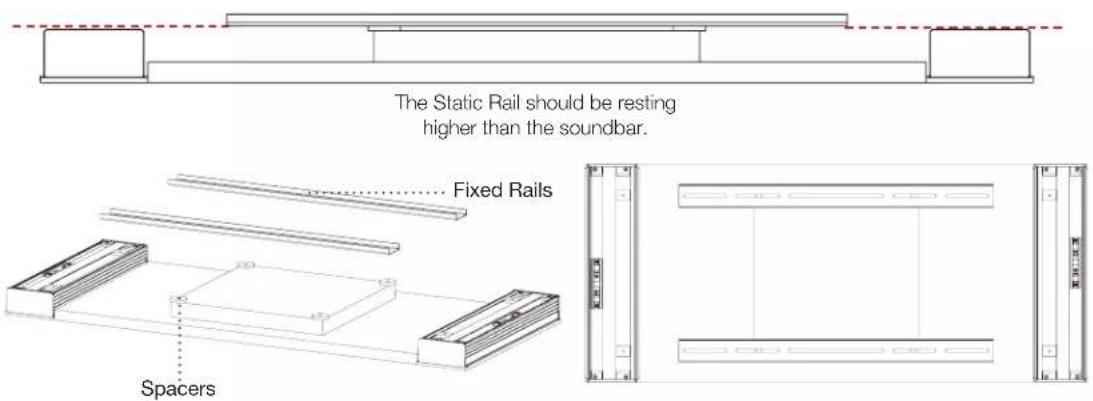
- Position the two static rails (A) over the plastic spacers.
• These rails should be horizontally oriented and fit within the TV profile.
• They should also be sitting level with or higher than your soundbar.
Note: Now is an excellent time to determine if your static rails require additional spacers to ensure they sit higher than your Décor Soundbar. Use the spacers (G, H, I) provided in your Mounting KIT to adequately raise the level of your rails.
Feel free to use the included VESA screws (KIT0108 - AA, BB, CC, DD, EE, FF) throughout the installation process to keep all mounting components aligned with the VESA mounting points.
3
Fasten qty 4 length appropriate Threaded Shafts (D, E) onto the four extrusion brackets. Do not tighten the shafts fully, as some final adjustments may be required in later steps.

natural_image
Technical diagram showing a mechanical assembly with cross-sectional and top views, including a hand pointing to a cylindrical component (no text or symbols present)4
Putting the Sliding Rail Assembly together.
The mounting configuration you have received requires two Sliding Rail assemblies to be constructed.
For this you will need:
4x Sliding Rails (B)
4x Sliding Rail Brackets (C)
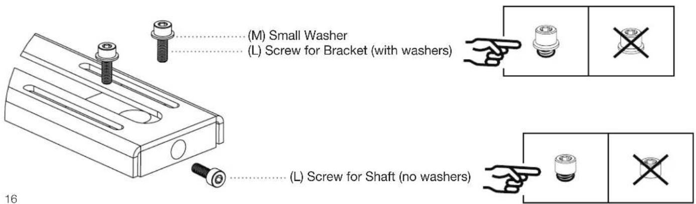
8x Small Washer (M)
12x Shaft / Bracket Screws (L)
Constructing the Sliding Rail Assembly:
a. Each of the Sliding Rail Brackets (QTY 4x) require 4x Shaft / Bracket Screws to fasten onto the Sliding Rails, and
b. 1x Shaft / Bracket Screws to secure the Threaded Shaft.
Place the fastened bracket onto the corresponding section of the Sliding Rail (show double-slotted section of rail). PLEASE DO NOT TIGHTEN THE SCREWS ALL THE WAY.
5
Spacers (KIT0108-H)
Before you proceed any further, please take a moment to ensure that each Fixed Rail has two metal spacers over each of their VESA mounting points. This is to ensure that when tightening the VESA screws, the rail compression does not exceed their mechanical thresholds.
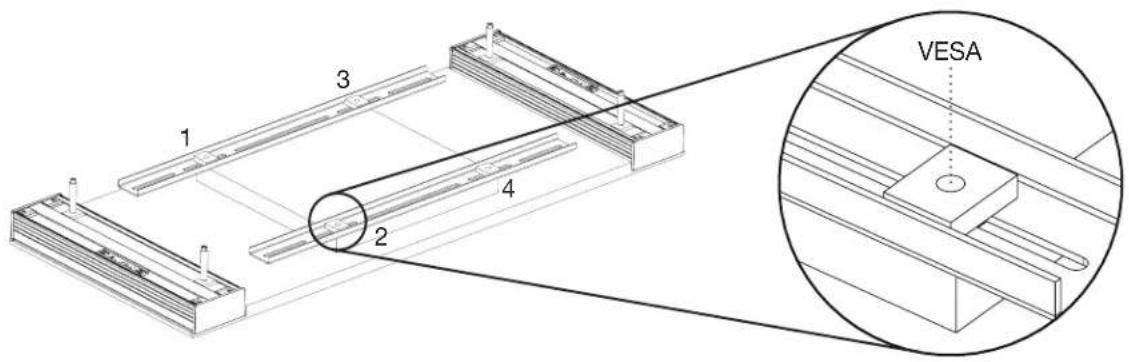
6
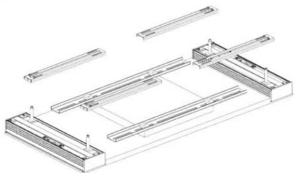
Once assembled, position each of the four Sliding Rail assemblies over the previously positioned Static Rails (and their spacers), with the bracket side pointed downwards (as shown).
natural_image
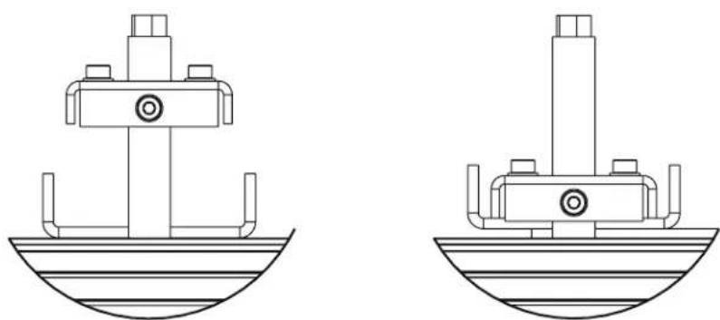
Technical line drawing of a structural frame assembly (no text or symbols)Slide the assembled Sliding Rails over the Threaded Shaft. The Sliding Rails should have one end through the Threaded Shaft and the other resting on the Static Rails.
natural_image
Technical line drawings of two identical mechanical or structural components with no visible text or symbols7
Tighten the threaded shafts and their corresponding screws on the sliding brackets.

8
To secure the rail position, you will need:
4x Anchor Screws (J)
8x Washers (F)
4x Nuts (K)
Anchor Screw Installation
At this point, the positioning of ALL Rails will not change, and the positioning will be fixed by the Anchor Screws. To install the Anchor Screw, insert the screw from the underside of the Rail below the bottom-most VESA mounting points and thread the nut/washer combo onto the screw from the opposite side. PLEASE DO NOT TIGHTEN THE SCREWS ALL THE WAY, OR INSTALL THEM VIA THE VESA MOUNTING INSERTS.

9
For this step, you will need:
1x Third-party TV Bracket
4x Provided VESA Mounting Screws (AA, BB, CC, DD, EE, FF)
Remove the untightened VESA Mounting Screws (QTY 4x) that have been aligning the Assembly so far.
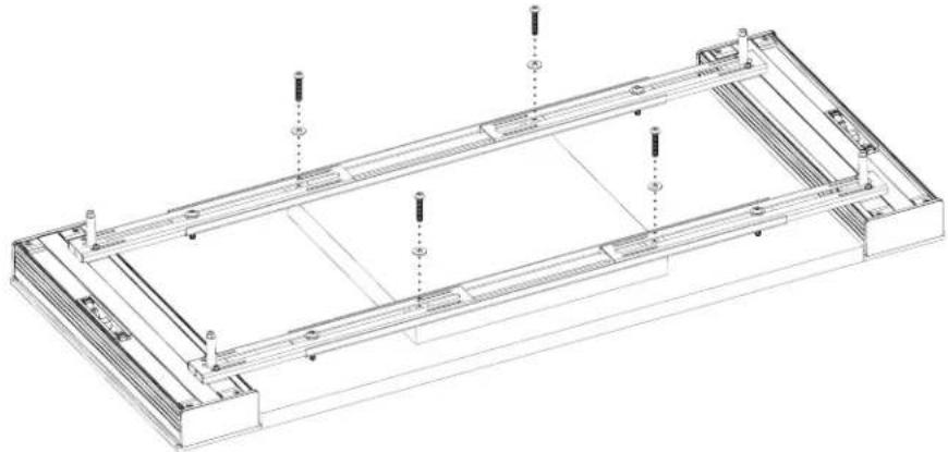
natural_image
Technical line drawing of a rectangular electronic device with mounting holes and internal compartments (no text or symbols)With the Anchor Screws in place, please proceed to place your third-party TV Bracket over the assemblies.
With the TV Bracket in position, re-insert the VESA Mounting Screws you have been using to align the assembly and begin tightening them with the provided Torx Keys.

natural_image
Technical line drawing of two structural frame assemblies with mounting brackets and support columns (no text or symbols)
CAUTION: THIS IS A TWO PERSON PROCEDURE. TWO PEOPLE ARE NEEDED TO CARRY OUT THE INSTRUCTIONS OUTLINED BELOW. BE CAREFUL NOT TO DAMAGE TV AND SPEAKER DRIVERS DURING BRACKET INSTALLATION.

CAUTION: CAREFULLY LIFT BY RAILS. DO NOT LIFT BY TV EDGE. Support entire bracket assembly and place onto TV Mount on wall (purchased separately). Follow TV Mounting instructions. WHEN HANGING THE TV, SUPPORT BOTH THE TV AND THE ATTACHED SPEAKERS.
Once all screws have been adequately tightened, lift your TV and Soundbar and mount the assembly onto your third-party wall mounting bracket.
natural_image
Two figures in a standing position holding rectangular blocks, no text or symbols present3SC SPEAKER INSTALLATION ONTO TV
Applies to ALL 3SC speaker configurations and lengths.
Parts required:
3x Soundbar
3x Cloth Grille (optional)
2x KIT0108
Cloth grille
and, two separate kits listed below:
1x 1S/1C/1SC
1x 2S/2SC
2x KIT0102 (S)
2x KIT0107 (M)
2x KIT0103 (L)
PREPARING YOUR DÉCOR SOUNDBAR FOR INSTALLATION
The best way to ensure a smooth assembly is to mount your new soundbar to the TV while they're on the floor. First, you should ensure that the floor is clear of any debris that may damage your TV or Soundbar. We recommend using a thick blanket to prevent any scratches or direct contact with the floor.
PREPARING YOUR TV FOR SPEAKER INSTALLATION
Place your TV face down on the ground and ensure adequate space to maneuver around during installation.

GRILLE FIT
If you ordered a Cloth Grille, please remove the grille(s) from its packaging and place it on your Décor Soundbar now. This will ensure the front faces of the TV and soundbars are flush with one another. In addition, if you ordered a contour grille, please ensure it is aligned with the corresponding TV contour.

FLUSH FIT
Position your new Décor soundbars face down in the desired positions, relative to your television. When face down, please ensure that the mounting channel is always closest to the TV. The soundbars should be flush with the side of the TV, and the top and bottom should be aligned with the top and bottom of the TV as well.

1S/1C/1SC COMPONENTS LIST
1x Soundbar

natural_image
Pure diagram of a rectangular panel with six circular components, no text or symbols present1x KIT0104 or KIT0105 or KIT0106

natural_image
Simple line drawing of a rectangular object with horizontal lines and rounded ends, labeled (A) 2x at the top (no text or symbols on the object itself)(A) Fixed Rail length will differ between KIT0104 / KIT0105 / KIT0106
12x 3 Plastic Spacers

2x Threaded Shafts (long)
2x Threaded Shafts (short)
4x Anchor Screws

2x Sliding Rail Assemblies
1x KIT0108
3x Torx Wrenches

4x Rail Spacers

VESA Screws M6
KIT0108
VESA Screws M8
KIT0108

2S/2SC COMPONENTS LIST
2x Soundbar

natural_image
Pure diagram of a rectangular panel with circular components and a 2x label, no text or symbols present.- 2 MDF Grilles (if option selection)
- 4x Extrusion Brackets
1x KIT0102 or KIT0107 or KIT0103
(A) 2x

(A) Fixed Rail length will differ between KIT0102 (S) / KIT0107 (M) / KIT0103 (L)
12x 3 Plastic Spacers
(G) 12x

(H) 12x (I) 12x

2x Threaded Shafts (long)
2x Threaded Shafts (short) 4x Anchor Screws
2x Sliding Rail Assemblies
(E) 4x
(J) 8x

(D) 4x

(K) 8x


(L) 12x

(C) 4x

(M) 12x(F)8x
1x KIT0108
3x Torx Wrenches
(II) 1x

VESA Screws M6
KIT0108
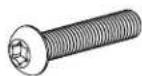
(AA) 4x

VESA Screws M8
KIT0108
(BB) 4 ×
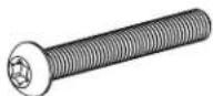
(EE) 4x
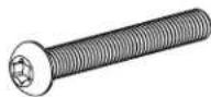
(CC) 4x
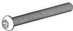
(FF) 4x
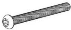
4x Rail Spacers
(HH) 4x
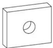
(LL) 1x
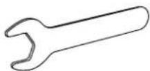
1
Remove the tape securing both Extrusion Brackets to the soundbar.
Slide all extrusion brackets (located on the mounting channel) to roughly align with the VESA mounting points on your TV.

2
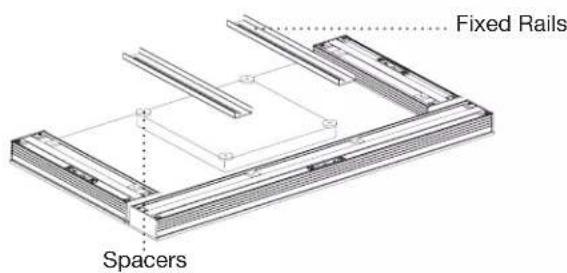
To protect the TV from the Fixed Rails, position Plastic Spacers (QTY 4x) over the four VESA mounting inserts.
- By default, please start with (I) 10mm spacers (these are the thickest).
- Position the two static rails (A) over the plastic spacers.
• These rails should be horizontally oriented and fit within the TV profile..
• They should also be sitting level with or higher than your soundbar.
Note: Now is an excellent time to determine if your static rails require additional spacers to ensure they sit higher than your Décor Soundbar. Use the spacers (G, H, I) provided in your Mounting KIT to adequately raise the level of your rails.
Feel free to use the included VESA screws (KIT0108 - AA, BB, CC, DD, EE, FF) throughout the installation process to keep all mounting components aligned with the VESA mounting points.


natural_image
Architectural floor plan lines showing room layouts and structural elements (no text or labels)3
Fasten length appropriate Threaded Shafts (D or E – QTY 4x) onto the four extrusion brackets. Do not tighten the shafts fully, as some final adjustments may be required in later steps.

natural_image
Technical illustration of a mechanical assembly with cross-sectional views and a hand pointing to a cylindrical component (no text or symbols present)4
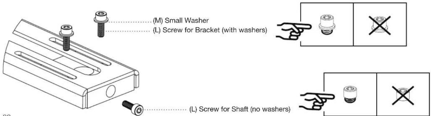
Putting the Sliding Rail Assembly together:
The mounting configuration you have received requires two Sliding Rail assemblies to be constructed.
For this you will need:
6x Sliding Rails (B)
6x Sliding Rail Brackets (C)
12x Small Washer (M)
18x Shaft / Bracket Screws (L)
Constructing the Sliding Rail Assembly:
a. Each of the Sliding Rail Brackets (QTY 6x) require 2x Shaft / Bracket Screws to fasten onto the Sliding Rails, and
b. 1x Shaft / Bracket Screws to secure the Threaded Shaft.
Place the fasten bracket onto its corresponding section of the Sliding Rail. PLEASE DO NOT TIGHTEN THE SCREWS ALL THE WAY.
5
Spacers (KIT0108-H)
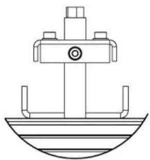
Before you proceed any further, please take a moment to ensure that four metal spacers over each of the VESA mounting points. This is to ensure that when tightening the VESA screws, the rail compression does not exceed their mechanical thresholds, while also allowing the VESA screw to pass through and into the TV.

6
Once assembled, position each of the two Sliding Rail assemblies over the previously positioned Fixed Rails (and their spacers), with the bracket side pointed downwards.

natural_image
Technical line drawing of a structural assembly with layered components and mounting brackets (no text or symbols)Slide the assembled Sliding Rails over the Threaded Shaft. The Sliding Rails should have one end through the Threaded Shaft and the other resting on the Static Rails.
natural_image
Technical line drawing of a mechanical assembly with no visible text or symbols
natural_image
Technical line drawing of a mechanical component with no visible text or symbols7
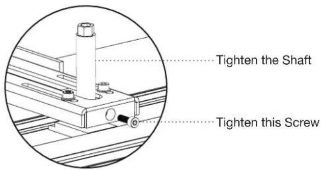
Please tighten the threaded shafts and their corresponding screws on the sliding brackets.
8
To secure the rail position, you will need:
2x Anchor Screws (J)
4x Washers (F)
2x Nuts (K)
Anchor Screw Installation
At this point, the positioning of ALL Rails will not change, and the positioning will be fixed by the Anchor Screws. To install the Anchor Screw, insert the screw from the underside of the Rail below the bottom-most VESA mounting points and thread the nut/washer combo onto the screw from the opposite side. PLEASE DO NOT TIGHTEN THE SCREWS ALL THE WAY, OR INSTALL THEM VIA THE VESA MOUNTING INSERTS.

9
With your horizontal soundbar (1C/1S/1SC) mounting almost complete, begin the installation of your two vertical soundbars (2S/2SC). Start with the Fixed Rails (QTY 4x).

Please position the Fixed Rails (QTY 2x) over the previously installed rail set and ensure alignment over the TV's VESA inserts. Please use the provided VESA screws to maintain alignment throughout the remainder of the installation process.
10
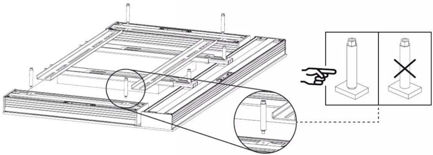
Install the Threaded Shafts (QTY 4x) for your two vertical soundbars. These should be roughly in alignment with Fixed Rails you just installed. Please tighten the Threaded Shafts (QTY 4x), but do not tighten them all the way.
11
Please place four additional metal spacers over the (2S/2SC).

12
Please collect the four additional Sliding Rail assemblies that were assembled in step 4 of these instructions. These will be positioned in the next step. If you have any questions relating to the Sliding Rail assembly, please refer to step 4.

natural_image
Technical line drawing of a mechanical component with mounting holes and a 4x multiplier label (no text or symbols on the diagram itself)13
Position each of the four Sliding Rail assemblies over the Fixed Rails (and their spacers), with the bracket side pointed downwards.

natural_image
Technical line drawing of a structural frame assembly with multiple horizontal supports and support columns (no text or symbols)Slide the assembled Sliding Rails over the Threaded Shaft. The Sliding Rails should have one end through the Threaded Shaft and the other resting on the Static Rails.

natural_image
Technical line drawing of a mechanical assembly with no visible text or symbols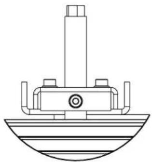
natural_image
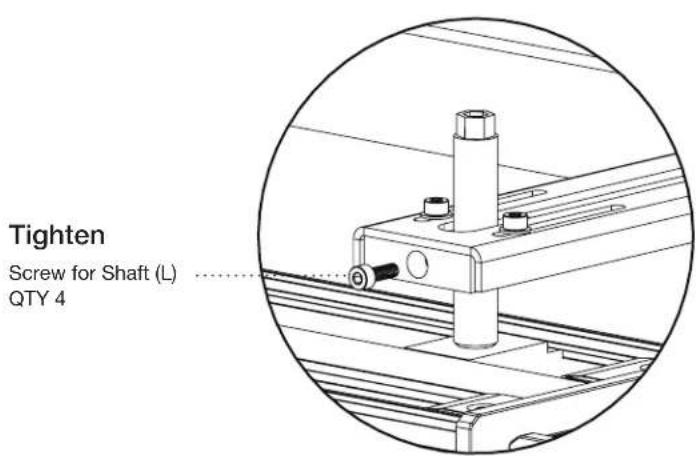
Technical line drawing of a mechanical component with no visible text or symbolsWith the Sliding Rails positioned as far down as they can go, please tighten the shaft screw (L) on each of the four Sliding Rails.
14
Securing the rail position.
At this point, the positioning of ALL Rails will not change, and the positioning will be fixed by the Anchor Screws. To install the Anchor Screw, insert the screw from the underside of the Rail below the bottom-most VESA mounting points and thread the nut/washer combo onto the screw from the opposite side. PLEASE DO NOT TIGHTEN THE SCREWS ALL THE WAY, OR INSTALL THEM VIA THE VESA MOUNTING INSERTS.
15
For this step, you will need:
1x Third-party TV Bracket
4x Provided VESA Mounting Screws (AA, BB, CC, DD, EE, FF)
Remove the untightened VESA Mounting Screws (QTY 4x) that have been aligning the Assembly so far.
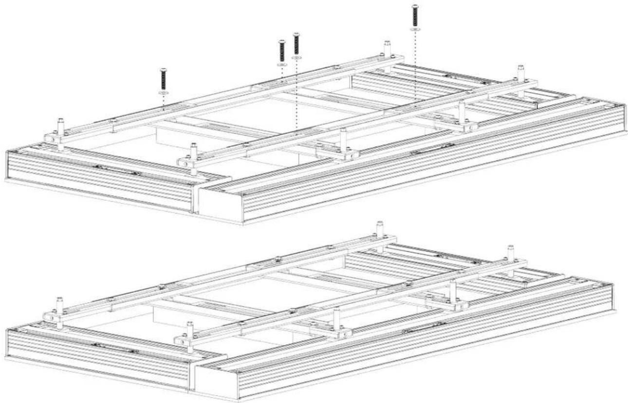
With the Anchor Screws in place, please proceed to place your third-party TV Bracket over the assemblies.
With the TV Bracket in position, re-insert the VESA Mounting Screws you have been using to align the assembly and begin tightening them with the provided Torx Keys.
natural_image
Technical line drawings of two structural frame assemblies with mounting brackets and support posts (no text or symbols)
CAUTION: THIS IS A TWO PERSON PROCEDURE. TWO PEOPLE ARE NEEDED TO CARRY OUT THE INSTRUCTIONS OUTLINED BELOW. BE CAREFUL NOT TO DAMAGE TV AND SPEAKER DRIVERS DURING BRACKET INSTALLATION.

CAUTION: CAREFULLY LIFT BY RAILS. DO NOT LIFT BY TV EDGE. Support entire bracket assembly and place onto TV Mount on wall (purchased separately). Follow TV Mounting instructions. WHEN HANGING THE TV, SUPPORT BOTH THE TV AND THE ATTACHED SPEAKERS.
Once all screws have been adequately tightened, lift your TV and Soundbar and mount the assembly onto your third-party wall mounting bracket.

natural_image
Two figures in a physical exercise or martial arts stance, holding rectangular objects (no text or symbols visible)1S/1C/1SC WALL MOUNT INSTALLATION (43"-64.9" LENGTH MODELS)
1
Affix Rubber Bumpers to the back of the speaker.

natural_image
Technical line drawing of a mechanical assembly with three circular insets showing close-ups of components (no text or symbols)2
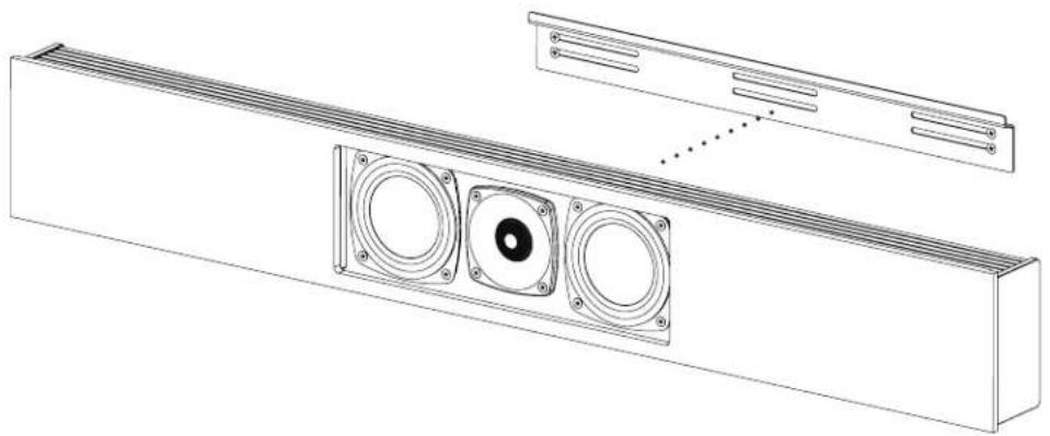
Ensuring the Wall Mount Bracket is level, attach it to the wall using screws (not supplied). Seek professional advice for the appropriate screw hardware for your wall construction. Depending on the weight of your soundbar and the construction of walls, it is highly recommended you screw into wall studs.

natural_image
Pure technical line drawing of a mechanical component with bolt holes and dotted lines indicating motion (no text or symbols)3
Hang the speaker on the wall.
natural_image
Technical line drawing of a mechanical assembly with two circular components and a rectangular housing (no text or symbols)1S/1C/1SC WALL MOUNT INSTALLATION (65"-100" LENGTH MODELS)
1
Affix rubber bumpers to the back of the speaker.

natural_image
Technical line drawing of a mechanical assembly with two views showing internal components (no text or symbols)2
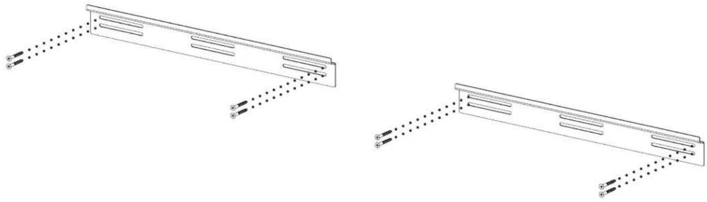
Ensuring the Wall Mount Brackets are level, attach them to the wall using screws (not supplied). Seek professional advice for the appropriate screw hardware for your wall construction. Depending on the weight of your soundbar and the construction of walls, it is highly recommended you screw into wall studs.
natural_image
Technical line drawing of two mechanical components with dotted alignment lines (no text or symbols)3
Hang speaker on the Wall Mount Brackets.

natural_image
Technical line drawing of a multi-panel industrial enclosure with circular components and mounting brackets (no text or symbols)2S/2C WALL MOUNT INSTALLATION (ALL MODELS)
1
Align both Extrusion Brackets side by side.

natural_image
Technical line drawing of a vertical cabinet with an inset close-up showing internal components (no text or symbols)2
Attach the Extrusion Side Bracket to the Extrusion Brackets using the included Flanged Screws.

natural_image
Technical line drawing of a mechanical assembly with two views showing internal components and mounting holes (no text or symbols)Affix the Rubber Pad to the bottom of the speaker.

natural_image
Technical line drawing of a mechanical assembly with three circular insets showing internal components (no text or symbols)4
Screw the Wall Mount Bracket onto the wall using screws (not supplied). Seek professional advice for the appropriate screw hardware for your wall construction. Depending on the weight of your soundbar and the construction of walls, it is highly recommended you screw into wall studs.

natural_image
Technical line drawing showing two metal bracket assemblies with screws and mounting holes, no text or symbols present5
Hang speaker on the wall.

natural_image
Diagram of two tall speakers with circular speaker holes, connected by a dotted line to a small rectangular component (no text or symbols)

- TABLE OF CONTENTS
- 1S/1C/1SC Speaker Installation onto TV.... 3
- 2S/2SC Speaker Installation onto TV.... 11
- 3SC Speaker Installation onto TV 20
- 1S/1C/1SC Wall Mount Installation (43"-64.9" Length Models) ...... 35
- 1S/1C/1SC Wall Mount Installation (65"-100" Length Models) ...... 36
- 2S/2C Wall Mount Installation (All Models) 38
- An Important Note About TV Mounting Bracket:
- 1S/1C/1SC SPEAKER INSTALLATION ONTO TV
- PREPARING YOUR DÉCOR SOUNDBAR FOR INSTALLATION
- PREPARING YOUR TV FOR SPEAKER INSTALLATION
- GRILLE FIT
- FLUSH FIT
- 1S/1C/1SC COMPONENTS LIST
- 1x Soundbar
- 1x KIT0104 or KIT0105 or KIT0106
- 1x KIT0108
- 1
- Remove the tape securing both Extrusion Brackets to the soundbar.
- 2
- To protect the TV from the Fixed Rails, position the Plastic Spacers over the four VESA mounting inserts.
- 3
- 4
- Putting the Sliding Rail Assembly together.
- Constructing the Sliding Rail Assembly:
- 5
- Spacers (KIT0108-H)
- 6
- 7
- 8
- Securing the rail position.
- Anchor Screw Installation
- 9
- For this step, you will need:
- 2S/2SC INSTALLATION INSTRUCTIONS ONTO TV
- 2S/2SC COMPONENTS LIST
- 2x Soundbar
- 1x KIT0102 or KIT0107 or KIT0103
- To protect the TV from the fixed rails, position QTY 4 Plastic spacers over the four VESA mounting inserts.
- 3SC SPEAKER INSTALLATION ONTO TV
- To protect the TV from the Fixed Rails, position Plastic Spacers (QTY 4x) over the four VESA mounting inserts.
- Putting the Sliding Rail Assembly together:
- 10
- 11
- 12
- 13
- 14
- 15
- 1S/1C/1SC WALL MOUNT INSTALLATION (43"-64.9" LENGTH MODELS)
- 1S/1C/1SC WALL MOUNT INSTALLATION (65"-100" LENGTH MODELS)
- 2S/2C WALL MOUNT INSTALLATION (ALL MODELS)
Brand : Paradigm
Model : Decor 1SC v2
Category : Loudspeaker