SF-B1001 - Home trainer Sunny Health & Fitness - Free user manual and instructions
Find the device manual for free SF-B1001 Sunny Health & Fitness in PDF.


User questions about SF-B1001 Sunny Health & Fitness
0 question about this device. Answer the ones you know or ask your own.
Ask a new question about this device
Download the instructions for your Home trainer in PDF format for free! Find your manual SF-B1001 - Sunny Health & Fitness and take your electronic device back in hand. On this page are published all the documents necessary for the use of your device. SF-B1001 by Sunny Health & Fitness.
USER MANUAL SF-B1001 Sunny Health & Fitness
natural_image
Line drawing of an exercise bike with visible components and wheels (no text or symbols)The specifications of this product may vary from this photo and are subject to change without notice.
IMPORTANT SAFETY NOTICE
Make sure you fully understand the following precautions before assembling and operating the machine:
- Once fully assembled, please check that all hardware parts such as bolts, nuts and washers are positioned and secured firmly.
- Please check regularly that the safety chain guard that protects the moving parts of the machine is secured and in good order.
- Please always check the seat post, seat slider, pedals and handlebar are secured firmly before getting on the bike.
- To lubricate all moving parts annually is recommended.
- In order to avoid entangling in any moving parts; do not wear loose clothing.
- Do not remove feet from the pedals while they are in motion.
- Always wear shoes when using the machine.
- Dry the bike after each use to remove sweat and moisture. Wipe the machine with a damp cloth, water and mild soap. Do not use a petroleum-based solvent to clean the machine, in order not to damage the finish.
- Please keep children away from the bike while it is in use. Do not allow children to use the bike. This bike is designed for adults, not children.
- Do not dismount the bike until the pedals have stopped moving completely.
- Stop exercise immediately if you feel any of the following symptoms: nausea, shortness of breath, faint, headache, pain, tightness in your chest or any discomfort.
- Do not place fingers or any other objects into the moving parts of the bike.
- Prior to any exercise, consult with your physician first to establish the exercise frequency, time and intensity appropriate for your particular age and conditioning.
- After exercising, please push down the tension controller to increase resistance so that the pedals will not rotate freely and possibly hurt someone.
- Maximum user's weight is 220LB.
- This equipment is designed for indoor and home use only, not intended for commercial use.
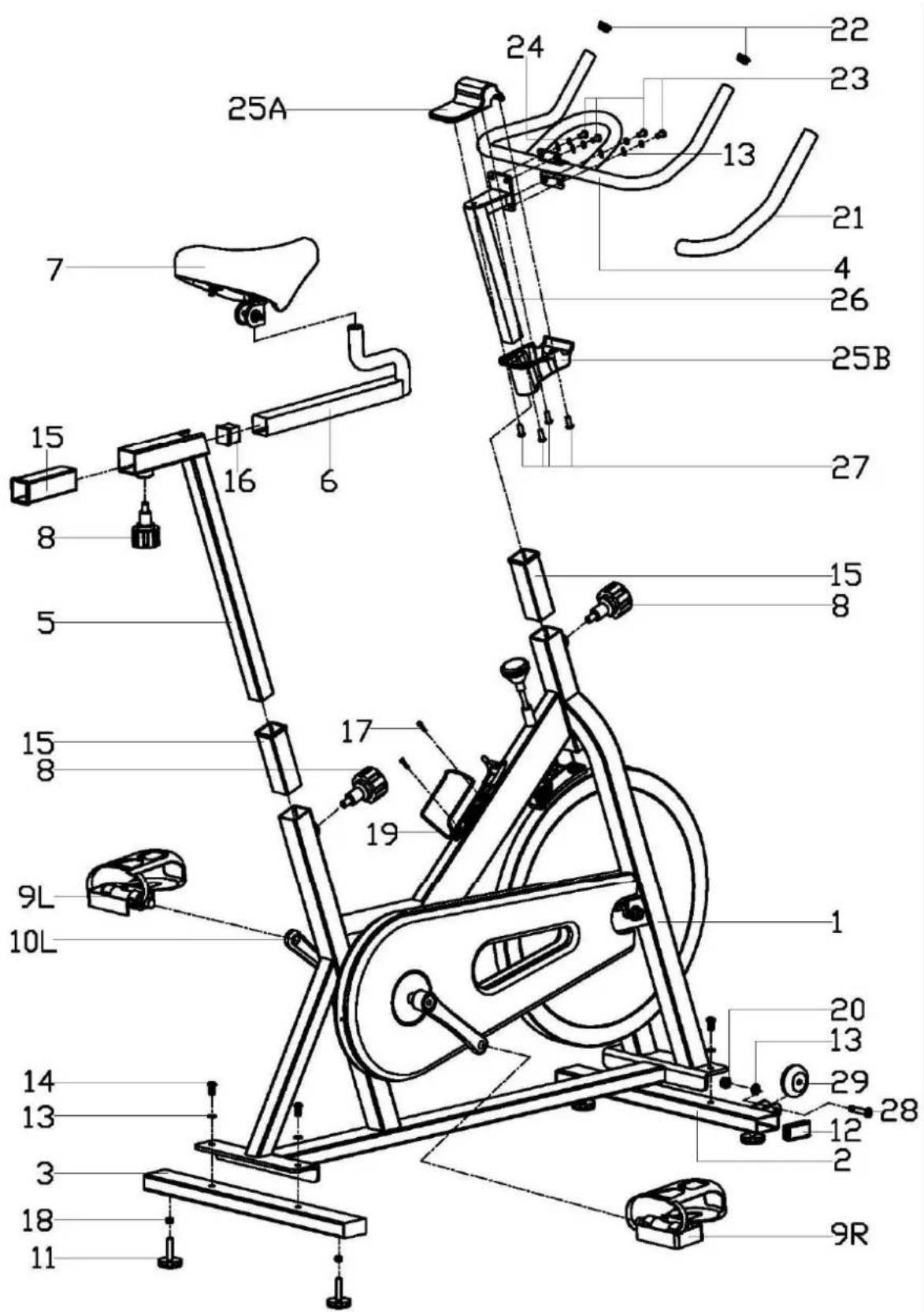
EXPLODED DIAGRAM
text_image
Technical diagram of an exercise bike with numbered components and labeled partsPARTS LIST
| Part No. | Description Qty | Part No. | Description Qty | ||
| 1 Main frame 1 16 Square cap | 1 | ||||
| 2 | Front stabilizer | 1 | 17 | Phillips tapping | 2 |
| 3 Rear stabilizer | 1 | 18 Hex nut M10 | 4 | ||
| 4 | Handlebar | 1 | 19 | Water bottle | 1 |
| 5 Seat post | 1 | 20 Nylon nut | 2 | ||
| 6 Seat slider 1 21 Foam grip | 2 | ||||
| 7 | Saddle | 1 | 22 | End cap | 2 |
| 8 Pop-pin knob | 3 | 23 Allen bolt | 4 | ||
| 9L/R | Pedal | 1each | 24 | Spring washer | 4 |
| 10L/R | Crank | 1each | 25 A/B | Handlebar cover | 1each |
| 11 | Leveler feet | 4 | 26 | Handlebar post | 1 |
| 12 | Oblong cap | 4 | 27 | Phillips screw | 4 |
| 13 | Flat washer | 10 | 28 | Allen bolt | 2 |
| 14 | Allen bolt | 4 | 29 | Roller | 2 |
| 15 | Plastic bushing | 3 | |||
NOTE: Most of the listed assembly hardware has been packaged separately, but some hardware items have been preinstalled in the identified assembly parts. In these instances, simply remove and reinstall the hardware as assembly is required.
Please reference the individual assembly steps and make note of all preinstalled hardware. Prior to assembly of this product, remove all components from the package and verify all the listed parts are supplied.
ASSEMBLY INSTRUCTIONS
Step A:
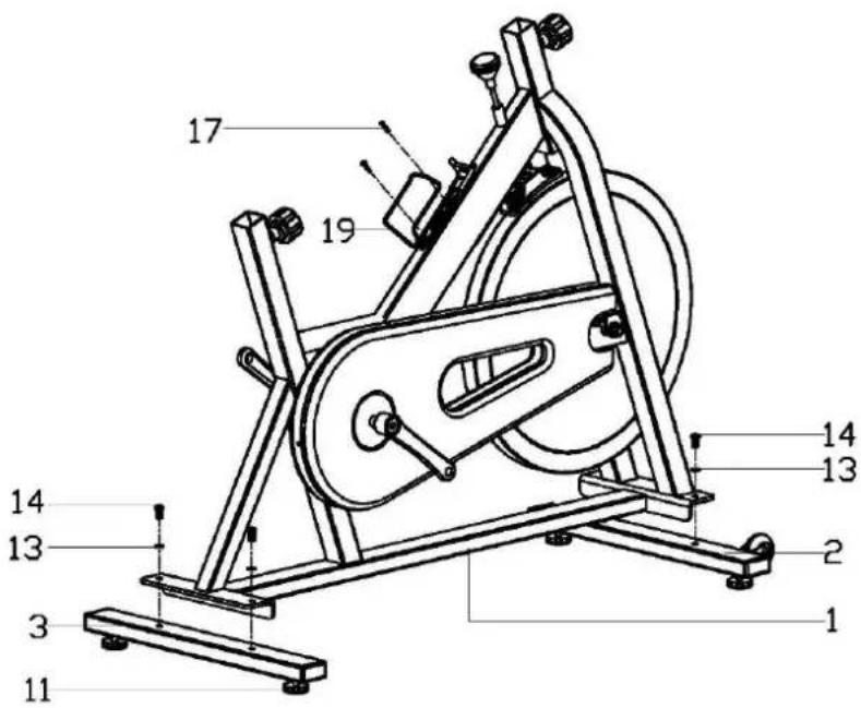
Install the Front stabilizer (2) and Rear stabilizer (3) to the Main frame (1) with the Bolts (14) and Flat washers (13). Please make sure that the Leveler feet are on the bottom and the transportation wheels are facing up and towards the front of the bike.
Attach the Water bottle holder (19) to the frame with the Screws (17).
Note: The Leveler feet (11) under the stabilizers can be adjusted to keep the equipment stable.
text_image
Technical diagram of an exercise machine with numbered components for identification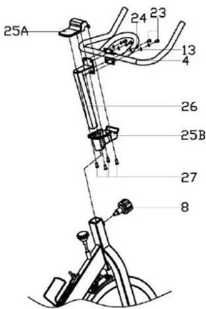
text_image
25A 24 23 13 4 26 25B 27 8Step B:
Attach the Handlebar (4) to the Handlebar post (26), secured with Allen bolts (23), Flat washers (13) and Spring washers (24). Set the lower Handlebar cover (25B) on the square tube of the Handlebar post (26) in alignment with the four grooves on the mouth of the lower Handlebar cover (25B). When the lower Handlebar cover (25B) slides to the top of the square tube of the Handlebar post (26); rotate the cover 45 degrees to align with the Handlebar (4). Use Phillips screws (27) to fix the Top cover (25A) to the lower Handlebar cover (25B), so that the Handlebar (4) and Handlebar post (26) are in between the Handlebar cover pieces (25A/B). Turn and loosen the Knob (8), pull the pin, and then insert the Handlebar assembly into the Main frame section simultaneously. Make sure the pin settles into the desired hole and then secure the Knob.
Step C:
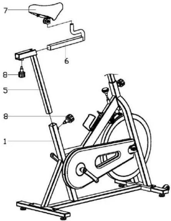
Lock the Saddle (7) on the Seat slider (6) tightly with wrench.
Adjust the front & back distance of Seat slider (6), then lock the Seat slider (6) on the Seat post (5) tightly with Pop-pin knob (8).
Insert the Seat post (5) to the rear upright tube of Main frame (1), then adjust the height properly and lock them tightly with Pop-pin knob (8).
Note: You could adjust the front & back distance of Seat slider (6) by loosing properly the Pop-pin knob (8) on Seat post (5); you could also adjust the height of Seat post (5) by loosing properly the Pop-pin knob (8) on the rear upright tube on Main frame (1).
Make sure the Saddle (7) is locked tightly on Seat slider (6) before moving.
text_image
Technical diagram of an exercise bike with numbered parts for identification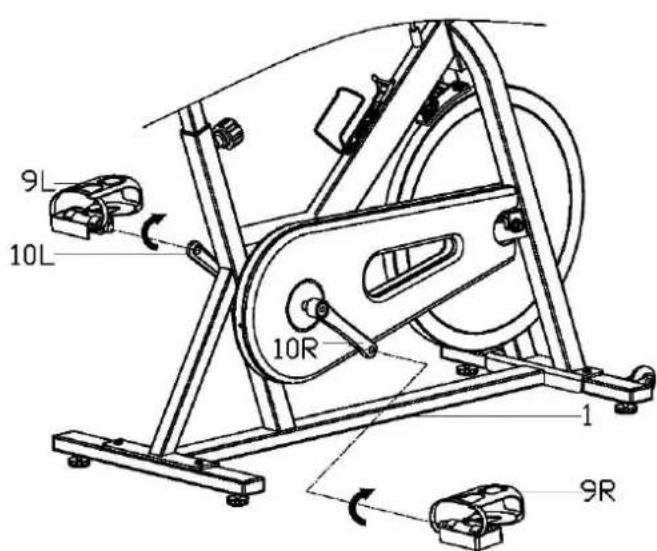
text_image
9L 10L 10R 1 9RStep D:
Attach the Pedals (9L/R) to the Cranks (10L/R) respectively, viewed from the rider's seated position.
Note: Both pedals are labeled, L FOR LEFT and R FOR RIGHT.
Important:
To tighten, turn the left pedal COUNTERCLOCKWISE and the right pedal CLOCKWISE.
OPERATION
Leveling the Bike
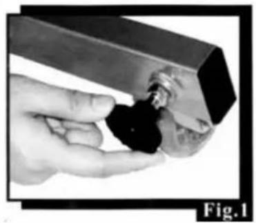
This bike can be leveled to compensate for uneven surfaces. To level the bike, please raise or lower four leveler feet located on the underside of the front and rear stabilizers (Fig.1).
Resistance Adjustment
Pedaling resistance is controlled by the tension control knob (Fig.2). To increase resistance turn the tension control knob clockwise (+). To decrease resistance turn the tension control knob counterclockwise (-). Resistance adjustment can be easily made at any time. Emergency brake is also equipped in the machine by simply pushing down the tension knob.
natural_image
Hand holding a small black object with a metallic component, labeled Fig.1 (no text or symbols on the object itself)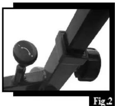
natural_image
Close-up of a mechanical lever mechanism with a dial and pivot knob (no text or symbols visible)Seat Adjustment
Appropriate seat height helps you exercise efficiently; reduces the risk of injury and makes you feel more comfortable. Adjusting the seat forward or backward helps you work on different lower body muscle groups.
- Place one pedal in the upward position. Place your foot in the toe clips, then get in the bike.
- If your leg is bent too much, you should move the seat up. If your foot can not touch the pedal or your leg is too straight, you should move the seat down.
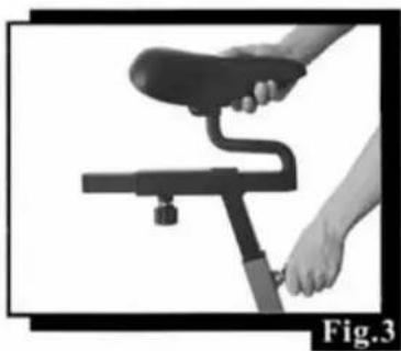
- Dismount the bike. Loosen and pull the pop pin (Fig.3), then raise or lower the seat post to the desired position. Make sure the pop pin settles into the desired hole and then secure it firmly.
- Loosen and pull the pop pin (Fig.4), then move the seat slider forward or backward to the desired position. When the seat slider is in the desired position, secure the pop pin firmly.
natural_image
Person using a stationary exercise bike with a curved leg and handle, labeled Fig.3 (no text or symbols on the diagram itself)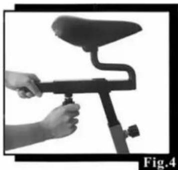
natural_image
Person using a stationary bike with a handle, labeled Fig.4 (no text or symbols on the diagram itself)Handlebar Adjustment
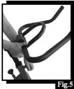
Loosen and pull the pop pin (Fig.5), then raise or lower the handlebar to the desired position for a more efficient & comfortable ride. Make sure the pop pin settles into the desired hole and then secure it firmly.
natural_image
Close-up of a hand holding a black mechanical strap, labeled Fig.5 (no text or symbols on the diagram itself)Pedal Strap Adjustment
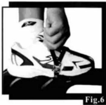
Place the ball of each foot in the toe clip until the front of the shoe fits snugly in the toe clip cage. Rotate one foot to within arm's reach, then pull up the strap until the toe clip cage fits the shoe snugly and insert the strap end back into the hoop of the toe clip (Fig.6). Repeat for the other foot.
natural_image
Black-and-white photo of a person adjusting a white shoe with a black clip (no visible text or symbols)Workout
Once you are sitting comfortably, begin pedaling slowly, with your hands resting comfortably on the handlebar. After you feel secure, you can change seat positions, hand positions and resistance levels for added enjoyment and variety during your workout.
Dismounting the Bike
Increase the resistance by turning the tension control knob clockwise until the flywheel stops, or pedal slower until you come to a complete stop.
Warning!
Do not dismount the bike or remove your feet from the pedals until the pedals have completely stopped.
Moving the Bike
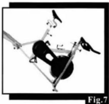
Carefully lift the rear stabilizer to move the bike to another location (Fig.7). Please gently move the bike as any sudden impact may affect the operation of the machine.