
ECEM2 - Coffee maker Estella Caffe - Free user manual and instructions
Find the device manual for free ECEM2 Estella Caffe in PDF.


| Product Type | Espresso Machine |
| Brand | Estella Caffe |
| Model | ECEM2 |
| Dimensions (L x W x H) | 25 cm x 30 cm x 35 cm |
| Weight | 4.5 kg |
| Power Supply | 120 V / 60 Hz |
| Power Consumption | 1450 W |
| Water Tank Capacity | 1.5 L |
| Bean Hopper Capacity | 250 g |
| Pump Pressure | 19 bar |
| Milk Frother | Steam wand, stainless steel |
| Programmable Settings | Brew strength, temperature, shot volume |
| Material | Stainless steel housing |
| Filter Type | Reusable stainless steel filter |
| Safety Features | Auto shut-off, overheat protection |
| Cleaning | Descaling alert, removable drip tray |
| Spare Parts | Available online from Estella Caffe |
| Warranty | 2 years |
Frequently Asked Questions - ECEM2 Estella Caffe
User questions about ECEM2 Estella Caffe
0 question about this device. Answer the ones you know or ask your own.
Ask a new question about this device
Download the instructions for your Coffee maker in PDF format for free! Find your manual ECEM2 - Estella Caffe and take your electronic device back in hand. On this page are published all the documents necessary for the use of your device. ECEM2 by Estella Caffe.
USER MANUAL ECEM2 Estella Caffe
natural_image
Exterior view of a modern espresso machine with visible branding and control panel (no text or symbols on main body)ESPRESSO MACHINES
236ECEM1 · 1 Group
236ECEM2 · 2 Group
236ECEM3 · 3 Group
12/2022
Estella CAFFE
INDEX
General 2-3
Specifications 3
Installation 4
Setup 4-5
Operation 5
Cleaning & Maintenance 6-7
Parts Diagram....8
Wiring Diagram (236ECEM1)....9
Wiring Diagram (236ECEM2)....10
Wiring Diagram (236ECEM3)....11
Note: Save these instructions for future reference.
GENERAL
- This manual specifies important operation, maintenance, and safety information. Please read carefully.
- After unpacking, please check to ensure your machine has not been damaged during shipping. Please notify a qualified technician regarding all questions or concerns before installing. Please note that the machine's packaging material, including plastic bag and Styrofoam, can be dangerous and should be kept out of reach of children.
- There is an identification label on the unit. Before operating, please check to ensure the power source corresponds to the rating shown on the identification label. The manufacturer is not responsible for issues resulting from improper installation and usage.
- Make sure to use a power source that corresponds with the unit's power rating.
- Please use No Fuse Breaker (NFB) that conforms to the safety regulation separately. Do NOT use a socket. The NFB should have a minimum contact space of 3 mm and provide electrical spike and drain protection. The ampere must be sufficient for providing the required electric current to this machine.
- Be sure to use a grounded power source to prevent electric shock and ensure the safety of this machine and its operators.
- The machine must be used in accordance with its original design. Additional use is inappropriate and dangerous.
- The steam wand, hot water wand, and brewing group can reach very hot temperatures. Use caution while operating.
- Please follow all cleaning and maintenance instructions specified in this manual in order to ensure peak operating efficiency.


Intertek
3058215
Estella CAFFE
- If the machine breaks down or functions abnormally, please turn off machine, disconnect the power source, and notify a qualified service technician to fix.
- Please use filtered and softened water. If using groundwater or tap water for brewing coffee, please soften it first. Unsoftened water will decompose dissolvable minerals and turn to limescale after boiling. The limescale will reduce the machine's thermal efficiency and machine's lifetime.
- This machine fills water automatically. If the water fails to fill (see troubleshooting section), the light touch panel will flash and power will be cut off automatically in order to protect the system. To resume normal functions, turn off the machine for 2-3 seconds and turn on the machine again.
- The heating element on this machine will not operate unless the water in the unit is at the minimum required level. When starting the machine without any water in the tank, heating will be delayed for about 60 seconds.
- Before operating the machine, please confirm that there is no water inside of the boiler. Temperature of water must be kept above freezing point. The damage caused by frozen water inside the tube or boiler won't be covered by the manufacturer.
- This unit is shipped from the factory with all water drained from the boiler. If you are to put the machine away for storage, please ensure that all water is drained. If water were to freeze inside the unit, it could cause damage.
SPECIFICATIONS
Every machine has an identification label placed on the front of the machine. The label includes information of model number, voltage, serial number, wattage, and its certificate. Please do not remove this label in order for technician to check electrical information in the future.
| 236ECEM1 236ECEM2 236ECEM3 | |||
| Groups | 1 2 3 | ||
| Boiler Capacity | 6 Qt. 13 Qt. 19 Qt. | ||
| Voltage | 110-120V 220-240V | 220-240V | |
| Wattage | 2000W | 4700W | 6500W |
| Weight | 97 lb. | 141 lb. | 179 lb. |
| Recommended Circuit Amperage | 20A | 30A | 50A |
| Dimensions (in) WxDxH | 1912" × 21" × 2234" | 2712" × 21" × 2234" | 37" × 21" × 2234" |
INSTALLATION
- A cold water connection is required for this unit to function properly.
- Contact a qualified technician to ensure that your electrical and water setup are correct to the specifications of the machine.
- This machine comes hardwired (no plug) and a qualified electrician is required for installation.
- A technician is also required to connect the existing waterline and check the filtration system before starting. Operating with poor water conditions can void the warranty.
- Use an independent breaker for this machine which conforms to safety regulations.
• Total Dissolved Solids: Minimum 50 PPM, Maximum 125 PPM
• Total Hardness: Minimum 3 GPG, Maximum 5 GPG - pH: 6.5\~7.5
• Free Chlorine: Maximum 0.5 PPM
• Total Chlorine: Maximum 0.5 PPM
• Minimum amount of water pressure: 29-43 PSI
SETUP
Starting the Automatic Machine
- Check and confirm that water source is in normal working order.
- Turn the power switch to On to initiate automatic system check. If boiler water level is not in the green zone, wait until the automatic water replenishment process is complete before proceeding to the next step.
- Heating will stop when boiler pressure reaches approximately 1.2 bars (factory default setting). Do not operate machine until steam pressure gauge reading is in the green zone.
Output Volume and Frequency Setup
- There are two identical button suites on 2 group models and three identical button suites on 3 group models.
- No default coffee output setting is provided. Settings must be made manually during setup.
-
If you are using a multi-cup machine, settings made on the farthest right hand side button suite will serve as default for the others. So, start from the right hand side and work your way to the left.
-
To program your machine, turn the output volume setup switch ON (Fig. 1).
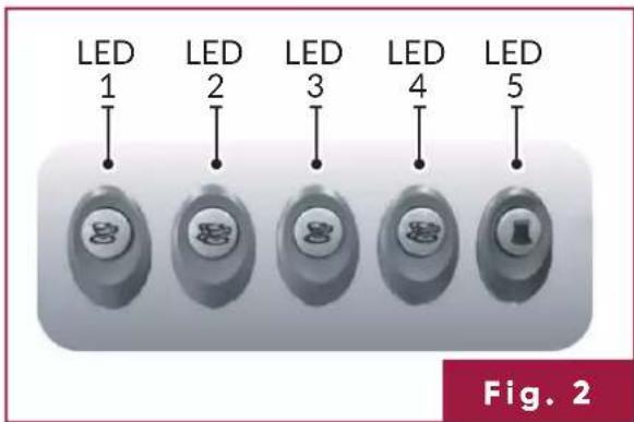
- The output LEDs (Fig. 2) should be lit with the 5th button flashing, indicating the machine is in setup mode.
Estella CAFFE
- To configure output button 1, press output button 1, which should light LED 1 and switch off all other LEDs. Press and hold the button until the desired output is reached. Users can measure fluid ounces or time dispensed for their settings.
- At this point, LED 1 should be off and LED's 2, 3 and 4 should be lit.
- Repeat steps 2 through 4 to set up output buttons 2, 3 and 4, respectively.
- The left set(s) of output buttons will mirror the value settings in the set of output buttons to its immediate right. Repeat steps 2 through 5 if different output volumes are desired for different groups.
- The fifth button of each group head will remain continuous flow. This means once you press this button, it will not turn off until pressed again.
- After completing setup, turn the output volume setup switch OFF to return the machine to normal operational mode.
OPERATION
Brewing
- Grind Coffee beans to a fine consistency.
- Fill the portafilter with coffee grounds and tamp.
- Secure the portafilter to the espresso machine with a quarter turn.
- Use any of the presets to brew or use the continuous flow button.
- If using continuous flow, the brewing will continue until it is pressed again, stopping the brewing process.
Automatic Reverse Flushing
- Reverse Flushing is recommended daily.
- Press the first and fifth buttons simultaneously to start automatic reverse flushing. Output buttons 2-4 in the control panel will light and start automatic reverse flushing from the right output system to the left.
- The default is 10 cleaning cycles.
- If you want to stop before the completion of all 10 cleaning cycles, press button 3.
- Flush one group after the other. You can press the third output button to skip the next output system. The system will stop automatically after all reverse flushing is finished.
Stopping the Machine
- After cleaning the machine, remove all liquids and solid matter from the water tray.
- Turn off the power.
- Open steam knob to release steam flow. Do not place any liquid under the steam tube during this process in to avoid system contamination.
CLEANING & MAINTENANCE
Machine Body
- Wipe machine exterior with soft, slightly dampened cloth daily before starting operations.
- If necessary, a mild, non-corrosive cleaning agent may be applied to the cloth. DO NOT spray cleaning agents directly on the machine body to avoid corrosion and possible damage to circuits.
Brewing System
- After each brewing cycle, remove the portafilter and press the manual water output button to remove all residual coffee grounds from the filter element.
- Then attach the portafilter to the machine again. CAUTION: DO NOT force the portafilter into the seat too tightly.
- Press the manual water output button, shake the portafilter, and remove residual coffee grounds from the inside.
- Place a reverse flushing silica plate in the portafilter, and apply about 2-3 grams of detergent. Attach the portafilter onto the machine and check for tightness.
- Next, start the auto backwashing process described in the operation section of this manual.
- After the backwashing is complete, remove the portafilter and silica plate. Press the manual water output button to allow residual cleaning solution in the brewing system to flow out. Turn water off after flushing for about one minute or until the water is clear and clean.
a. During reverse flushing, remove and wash the copper plate and filter element with clean tap water. Wipe with soft cloth.
b. If process is unable to sufficiently clean the plate and filter element, immerse the components overnight in a mild cleaning solution of 3 tsp detergent in 1 pint hot water.
- Rinse and reassemble components before restarting the espresso machine.
Portafilter and Filter Basket
- Rinse the portafilter with hot water after each brewing cycle to dissolve residual oils in the filter basket and outlet nozzle and prevent oils from affecting the quality of coffee.
- Disassemble the portafilter and place all parts in cleaning solution (3tsp of detergent in 1 pint hot water) for 24 hours to dissolve residual coffee oils. DO NOT immerse plastic portion in cleaning solution to avoid deterioration.
- Rinse all components with clean water. Wipe with a soft, clean cloth only.
Steam Tube
- After making steamed milk, use a slightly moistened soft cloth to wipe steam tube.
- After wiping, release a steam burst through the tube to remove any residual milk remaining in the nozzle.
- If hardened milk residuals remain in the steam tube, disassemble and immerse tube in hot water for about 20 minutes to soften. Reassemble and repeat step (1).
Estella CAFFE
Water Tray and Discharge Trough
- Turn off the machine and remove the water tray. Wash thoroughly with cleaning solution and rinse with water.
- After removing the water tray, wipe and remove sediments in the discharge trough with a wet cloth or napkin and wash with hot water to clear the discharge tube.
- If water does not discharge properly, place a teaspoon of detergent into the discharge trough and flush with hot water to dissolve residual oils in the tube.
- After the discharge trough is cleaned and the tray is dry, reassemble the water tray.
Boiler
To extend the serviceable life of your unit's boiler, or when you expect the machine to sit idle for a long period of time:
- Turn power to the machine OFF.
- Open the steam output to discharge pressure in the boiler. Continue until the pressure gauge reading falls to zero and steam discharge ends.
- Once complete, empty and clean the water tray and discharge trough.
Leave the steam output setting open following steam discharge. Steam output should remain open until after the machine is turned back on and hot water begins dripping from the steam tube.
Contact a service professional to delime the unit every 6 months.
Filter
The manufacturer recommends replacing the filter element on the resin exchange filter after processing 53 gallons of water (about 3,000 – 4,000 cups of coffee). This schedule can be expected to vary based on the quality of water used in your machine.
Estella
CAFFE
PARTS DIAGRAM
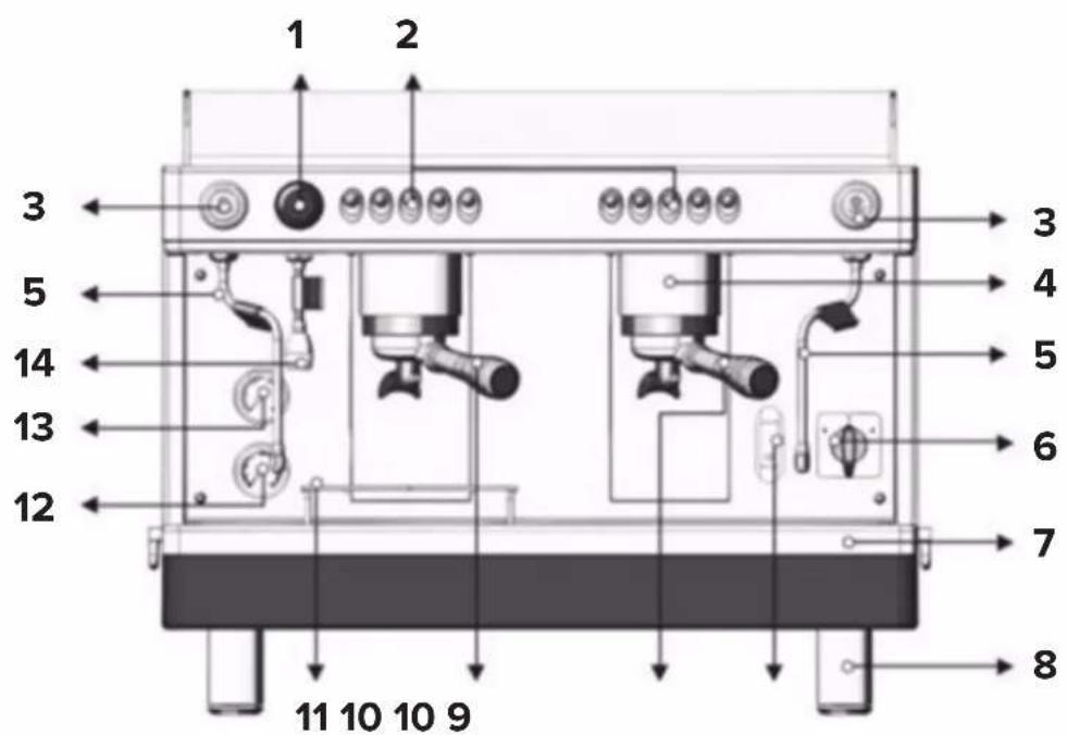
| Description | |
| 1 | Hot Water Knob |
| 2 | Espresso Brewing Unit Control Panel |
| 3 | Steam Knob |
| 4 | Brewing Group |
| 5 | Steam Tube |
| 6 | Main Power Switch |
| 7 | Drain Tray |
| Description | |
| 8 | Foot |
| 9 | Sight Glass (Boiler Water Level Check Window) |
| 10 | Espresso Filter Holder |
| 11 | Cup Rack |
| 12 | Water Pressure Gauge |
| 13 | Steam Pressure Gauge |
| 14 | Hot Water Wand |
WIRING DIAGRAM
236ECEM1

flowchart
graph TD
    A["110±10% VAC 1Φ 50/60Hz"] --> B["power switch"]
    B --> C["fan"]
    C --> D["SSR"]
    D --> E["P"]
    E --> F["heat element"]
    G["connector"] --> H["Motor & pump"]
    H --> I["operation panel"]
    I --> J["group1"]
    J --> K["Water level probe"]
    J --> L["Flowmeter(group1)"]
    J --> M["Dosing setting"]
    N["connector"] --> O["To SSR Terminal 3"]
    N --> P["To SSR Terminal 4"]
    Q["Group1 solenoid valve"] --> R["Temperature Protector"]
    S["Ground"] --> T["Ground"]
WIRING DIAGRAM
236ECEM2

flowchart
graph TD
    subgraph Power Source
        L1["220±10% VAC 1Φ 50/60Hz"]
        L2["NG"]
        G["Ground"]
    end

    subgraph Power Supply
        PowerSwitch["power switch"] --> Fan["Fan"]
        Fan --> SSR["SSR"]
        SSR --> P["P"]
        SSR --> Heat["heat element"]
        PowerSwitch --> Connector["connector"]
        PowerSwitch --> Motor["Motor & pump"]
        Motor --> OperationPanel["Operation panel"]
        OperationPanel --> Ground["Ground"]

    subgraph Control Panel
        PowerInfluence["Solaroid valve"] --> ToSR["Terminal 3"]
        ToSR --> Temperature["Temperature Protector"]
        Temperature --> Group1["solenoid valve"]
        Temperature --> Group2["solenoid valve"]
        Group1 --> Group2
        Group2 --> Group1
    end

    subgraph Control Bus
        Group2 --> WaterLevelProbe["Water level probe"]
        Group2 --> FlowmeterGroup2["Flowmeter(group2)"]
        Group2 --> FlowmeterGroup1["Flowmeter(group1)"]
        Group2 --> DosingSetting["Dosing setting"]
    end

    L1 --> PowerSwitch
    L2 --> PowerSwitch
    G --> PowerSwitch
    PowerSwitch --> PowerSwitch
    PowerSwitch --> PowerSwitch
    PowerSwitch --> PowerSwitch
    PowerSwitch --> PowerSwitch
    PowerSwitch --> PowerSwitch
    PowerSwitch --> PowerSwitch
    PowerSwitch --> PowerSwitch
    PowerSwitch --> PowerSwitch
    PowerSwitch --> PowerSwitch
    PowerSwitch --> PowerSwitch
    PowerSwitch --> PowerSwitch
    PowerSwitch --> PowerSwitch
    PowerSwitch --> PowerSwitch
    PowerSwitch --> PowerSwitch
    PowerSwitch --> P["P"]
    P --> P
    P --> P
    P --> P
    P --> P
    P --> P
    P --> P
    P --> P
    P --> P
    P --> P
    P --> P
    P --> P
    P --> P
    P --> P
    P --> P
    P --> P
    P --> P
    P --> P
    P --> P
    P --> P
    P --> P
    P --> P

    subgraph Control Panel
        Group2 --> Group1
        Group1 --> Group2
        Group2 --> WaterLevelProbe
        Group2 --> FlowmeterGroup2
        Group2 --> FlowmeterGroup1
        Group2 --> DosingSetting
    end
WIRING DIAGRAM
236ECEM3

flowchart
graph TD
    subgraph Power Source
        L1["220±10% VAC 1Φ 50/60Hz"]
        L2["1(N)"]
        G["G"]
    end

    subgraph Power Supply
        PowerSwitch["power switch"] -->|1 3| Fan["Fan"]
        Fan --> SSR["SSR"]
        SSR --> P["P"]
        SSR --> Motor["Motor & pump"]
        Motor --> Group1["Group1"]
        Motor --> Group2["Group2"]
        Motor --> Group3["Group3"]
        Group1 --> TemperatureProtector["Temperature Protector"]
        Group2 --> TemperatureProtector
        Group3 --> TemperatureProtector
    end

    subgraph Control Panel
        PowerSwitch -->|2 4| Motor
        Motor -->|3 4| Group1
        Group1 --> Group2
        Group2 --> Group3
        Group3 --> Ground
    end

    subgraph Control Procedure
        PowerSwitch -->|1 2 3| Connector
        Connector -->|1 2 3| Connector
        Connector --> group3["group3"]
        Group3 --> group2["group2"]
        Group2 --> group1["group1"]
        Group1 --> WaterLevelProbe["Water level probe"]
        Group2 --> FlowMeterGroup3["Flowmeter(group3)"]
        Group3 --> FlowMeterGroup2["Flowmeter(group2)"]
        Group1 --> FlowMeterGroup1["Flowmeter(group1)"]
        Group2 --> FlowMeterGroup1
        Group3 --> FlowMeterGroup1
        Group1 --> DosingSetting["Dosing setting"]
    end

    subgraph Control Panel
        PowerSwitch -->|4 5 6| Connector
        Connector --> WaterInflowSolenoidValve["Water inflow solenoid valve"]
        Connector --> ToSSRTerminal3["To SSR Terminal 3"]
        Connector --> ToSSRTerminal4["To SSR Terminal 4"]
        Connector --> Group3solenoidValve["Group3 solenoid valve"]
        Connector --> Group2solenoidValve["Group2 solenoid valve"]
        Connector --> Group1solenoidValve["Group1 solenoid valve"]
    end

    L1 --> PowerSwitch
    L2 --> PowerSwitch
    G --> PowerSwitch
    H2 --> TemperatureProtector
    H9 --> TemperatureProtector
    J7 --> TemperatureProtector
    J5 --> TemperatureProtector
    J4 --> TemperatureProtector
    J3 --> TemperatureProtector
    J1 --> TemperatureProtector
    J8 --> TemperatureProtector
    J7 --> TemperatureProtector
    J6 --> TemperatureProtector
    J5 --> TemperatureProtector
    J4 --> TemperatureProtector
    J3 --> TemperatureProtector
    J1 --> TemperatureProtector
    Ground --> Ground


- ESPRESSO MACHINES
- 236ECEM1 · 1 Group
- 236ECEM2 · 2 Group
- 236ECEM3 · 3 Group
- Estella CAFFE
- INDEX
- GENERAL
- SPECIFICATIONS
- INSTALLATION
- SETUP
- Starting the Automatic Machine
- Output Volume and Frequency Setup
- OPERATION
- Brewing
- Automatic Reverse Flushing
- Stopping the Machine
- CLEANING & MAINTENANCE
- Machine Body
- Brewing System
- Portafilter and Filter Basket
- Steam Tube
- Water Tray and Discharge Trough
- Boiler
- Filter
- Estella
- CAFFE
- PARTS DIAGRAM
- WIRING DIAGRAM
- 236ECEM1
- 236ECEM2
- 236ECEM3
Brand : Estella Caffe
Model : ECEM2
Category : Coffee maker