GR-2.3 - Coffee maker Fetco - Free user manual and instructions
Find the device manual for free GR-2.3 Fetco in PDF.


| Product Type | Commercial Coffee Brewer |
| Model | GR-2.3 |
| Brand | Fetco |
| Dimensions (W x D x H) | 12 x 18 x 24 inches (approx.) |
| Weight | 35 lbs (approx.) |
| Power Source | 120V AC, 60Hz, 1800W |
| Brew Capacity | Up to 2.3 gallons per hour |
| Water Reservoir | Built-in, with float valve (continuous supply) |
| Brew Basket Size | Standard commercial paper filter (12-14 cups) |
| Decanter Type | Airpot compatible (optional) or standard glass decanter |
| Brewing Function | Pour-over style with adjustable pre-infusion |
| Automatic Shutoff | Yes, after brew cycle complete |
| Temperature Control | Adjustable brew temperature (195-205°F) |
| Maintenance Alerts | Cleaning reminder cycle |
| Cleaning Method | Descaling with approved solution every 3 months recommended |
| Safety Features | Overheat protection, drip tray with float |
| Spare Parts Available | Yes, brew basket, warming plate, water filter, decanter |
| Repairability | Modular design; replaceable heating element and thermostat |
| Warranty | 1 year limited warranty (parts and labor) |
| Certifications | ETL, NSF listed |
Frequently Asked Questions - GR-2.3 Fetco
User questions about GR-2.3 Fetco
0 question about this device. Answer the ones you know or ask your own.
Ask a new question about this device
Download the instructions for your Coffee maker in PDF format for free! Find your manual GR-2.3 - Fetco and take your electronic device back in hand. On this page are published all the documents necessary for the use of your device. GR-2.3 by Fetco.
USER MANUAL GR-2.3 Fetco
GR Series Coffee Grinders
Models:
▶GR - 1.2 ▶GR - 2.2
▶GR - 1.3 ▶GR - 2.3
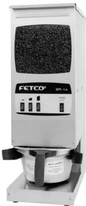
natural_image
Exterior view of a CETCO GR-L3 industrial coffee maker with visible branding and control panel (no readable text beyond branding)CULUS
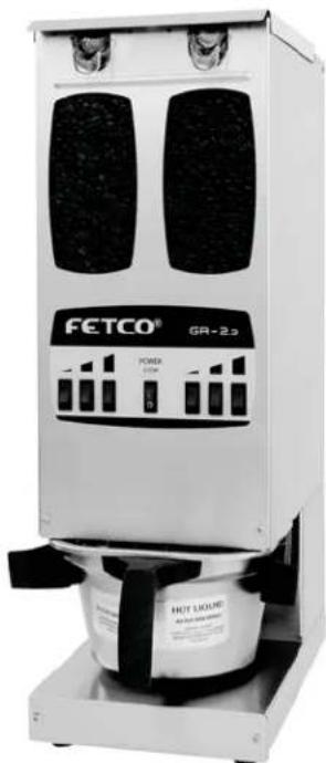
natural_image
Exterior view of a FETCO® industrial vacuum cleaner (no signage or text visible on the device body)cULusNSF
Driven To Pioneer Innovation™
Table of Contents
| Contact Information | 2 |
| Product Description/Features | 2 |
| Specifications | 2 |
| Dimensions & Utility Connections | 2 |
| Installation | 3 |
| Operating Instructions | 3 |
| Service and Support | 3 |
| Warranty | 3 |
| Principles of Operation | 4 |
| Grind Adjustment | 4 |
| Programming Instructions | 5 |
| Parts | 6 |
| Wiring Diagrams | 13 |
| Appendix A | 15 |
FETCO® is a trademark or trade name of Food Equipment Technologies Company. All other trademarks or trade names are trademarks or trade names of their respective owners.
Contact Information
FETCO
Food Equipment Technologies Company
600 Rose Road
Lake Zurich • IL • 60047-0429 • USA
Internet: www.fetco.com
Phone: (800) 338-2699 (US & Canada)
(847) 719-3000
Fax: (847) 719-3001
Email: sales@fetco.com
techsupport@fetco.com
Product Description/Features
GR-1.2- One permanent hopper - 2 Portion Sizes
GR-1.3- One permanent hopper – 3 Portion Sizes
GR-2.2- Dual removable hoppers - 2 Portion Sizes per side
GR-2.3- Dual removable hoppers - 3 Portion Sizes per side
▶FETCO slicing type grinding burrs
▶Self adjusting brew basket holder
▶ Fully automatic, with digital timer control
▶Front accessible & Service Friendly
▶Motor overload protection
▶ Control board overload protection
Specifications
Hopper Capacity: GR-1.2 & 1.3: 15 lbs. / 6.8 kg.
GR-2.2 & 2.3: 5 lbs. / 2.3 kg. each
Timer Range: 00.1 sec. - 999.0 sec.
Grind Rate*: 18 oz. / 510g per minute
Grind Setting Default: Medium
Brew Basket Size: 7" to 9" diameter
Electrical:
North America: 120 VAC, single phase
Type A motors: 5.2 amps, 0.67 HP
Type B motors: 9.5 amps, 0.74 HP
NEMA 5-15P plug/cord
Export: 230 VAC, single phase
Type B motors: 3.8 amps, 0.74 HP
* Grind rate is determined at medium grind with medium size, average to dark roast beans
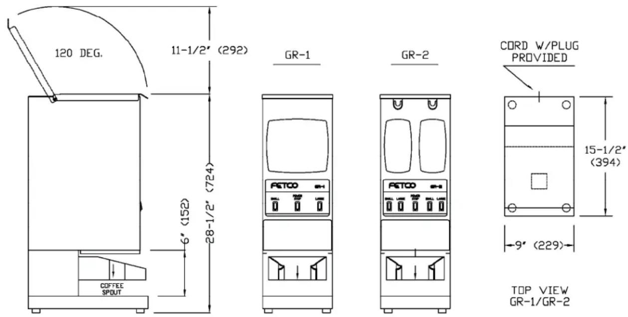
Dimensions & Utility Connections
Installation
Warning: Read this User's Guide before installing. Damage caused by improper installation will not be covered under warranty.
- Inspect the container for visual or hidden damage. The carrier must be notified of any punctured or damaged cartons immediately.
-
Install the grinder in selected location making sure surface is level, and that grinder will fit. Caution: Never push equipment against cords or wall outlets.
-
Remove cord from inside hopper and plug into the back of the grinder.
-
Before plugging grinder into 120 volt, 15 amp. wall outlet make sure outlet is not overloaded, a dedicated circuit is preferred.
-
Following the operating procedures below test grinder for proper operation.
-
If you need further assistance please call our Technical Support Dept. at 800-338-2699 or e-mail techsupport@fetco.com.

Warning: To prevent electrical shock, this unit must be properly grounded.
Operating Instructions
- Turn the on/off switch to the on position.
- The power switch will illuminate to indicate that the grinder has power.
-
Fill the hopper(s) with whole coffee beans.
-
The GR-2 models have two 5lb. removable hoppers. The hoppers must sit squarely on the floor of the hopper chamber. Before placing the hoppers inside the hopper chamber, make sure the chamber is clear of stray whole beans and debris, or the hoppers will not sit properly.
-
Both hoppers with their covers must be in place before operating the grinder.
-
Place the brew basket with paper coffee filter in the plastic holding arms.
-
The plastic arms will hold all FETCO brew baskets up to 16" X 6"; and will fit most other manufacturers' brew baskets.
-
For brew baskets that do not fit into the plastic arms, place the coffee filter on the lower shelf and grind directly into the filter.
-
Press the desired portion switch.
• See the Programming section for instructions on setting the various batch sizes.
- Allow grinder to complete its cycle then remove brew basket from plastic holding arms.
Cleaning:
a) Use stainless steel cleaner on all stainless steel surfaces. (Never use abrasives on these surfaces.)
b) Use damp cloth on other surfaces. Use mild detergent as needed.
c) Removable hoppers on GR-2 models are dishwasher safe (the covers are not).
d) After washing hoppers FETCO recommends hand drying them.
Service and Support
For service and support information, contact the Technical Support department. Our hours are 7:00 AM to 6:00 PM Central Time, Monday through Friday. Phone: (800) 338-2699 or (847) 719-3000. Email: techsupport@fetco.com.
Utilize only qualified beverage equipment service technicians for service. A Service Company Directory may be found on our web site, http://www.fetco.com.
Warranty
All FETCO grinders come with a limited warranty. Warranty service must be authorized by the Technical Support Department. A Return Authorization number will be issued for all parts replaced under warranty.
Principles of Operation
GR-1
When one of the start switches is pressed, the timer energizes the grinding motor. The coffee beans are fed into the grinding chamber by a rotating auger spring. When the timed cycle is complete, voltage is removed from grinding motor.
The power/stop switch is used only when it is necessary to interrupt the grind cycle before the cycle is finished.
GR-2
When one of the start switches is pressed, the timer simultaneously energizes the grinding motor and the hopper solenoid. The hopper solenoid opens the guillotine on the bottom of the hopper, which allows the coffee beans to drop into the grinder. The coffee beans are fed into the grinding chamber by a rotating auger spring.
When the timed cycle is complete, voltage is removed from the hopper solenoid and the guillotine closes, stopping the flow of beans out of the hopper. The auger spring continues to feed any remaining beans into the grinding chamber.
Several seconds after the guillotine closes, voltage is removed from the grinding motor. This delay ensures that all beans have passed through the grinding chamber, preventing cross contamination of different coffees.
The motor delay is factory set at 20 seconds, but can be adjusted if necessary. (See Programming section.)
The power/stop switch is used only when it is necessary to interrupt the grind cycle before the cycle is finished.
Grinder Foreign Object Protection
FETCO coffee grinders feature two types of overload protection to prevent damage to the unit if a foreign object enters the grinding chamber and stalls the motor.
- The control board is equipped with a thermal breaker with an audible alarm that will cut power to the motor if the control board overheats.
- The motor is equipped with a thermal breaker (no alarm) that will cut power to the motor if the motor overheats.
Once the foreign object is removed and the unit cools down, the thermal breakers will automatically reset.
Warning: If this occurs DO NOT TRY TO FIX THIS PROBLEM YOURSELF. Immediately unplug the grinder and call a qualified service technician.
Grind Adjustment
- Empty the hopper(s).
GR-1: Scoop out as many beans as possible. Lift the window up and sweep out the remaining beans.
GR-2: Remove both hoppers and dump the beans out. Place both hoppers back in grinder. - Press one of the large portion switches. This will clear the grinding chamber of any remaining beans.
- Remove the front cover. There are 2 screws in front and 2 underneath near the coffee outlet.
- Using a 7/8" or 22 mm wrench turn the retaining nut counter-clockwise at least one turn.
- Using a 3/8" to 1/2" standard screwdriver turn the adjustment screw clockwise for a finer grind, counterclockwise for a coarser grind. Note: Do not exceed more than a 1/4 turn in either direction.
- Turn retaining nut clockwise, locking adjustment screw in place.
- Grind a small amount of coffee beans to test the setting. Repeat the above steps if necessary.
To reset the grind setting to the factory default:
- Follow steps 1 - 4 of the grind adjustment procedure.
- Turn the adjustment screw clockwise until the grinding discs touch, then back off slightly.
- Using a marker, mark the twelve o'clock position of the adjustment screw.
- Turn the screw counter clockwise to just past the four o'clock position.
- Turn retaining nut clockwise locking adjustment screw in place.
- Test by grinding a small batch.
COARSE
FINE
Note: It may be necessary to adjust the grind time to compensate for the new grind setting. A finer grind will produce less ground coffee per minute and a coarser grind will produce more ground coffee per minute.
Programming Instructions
Software Version 1.2 and Above
(See Appendix A for units manufactured before August 2003)
▶ Turn the power switch off.
▶ Remove the lower cover.
▶ Turn the power switch on.
The currently programmed model number will flash briefly. (example: 12 = GR-1.2, 23 = GR-2.3)
▶ Then, if the software default settings are currently programmed, the display will read DEF. If not, the display will be blank.
▶ Hold SET for 5 seconds, until the display reads SET.
▶ Release SET, the software version will be displayed. (Example: 1.2, 1.3, etc.)
▶ Press SET. The display will read TYP briefly, followed by the currently programmed model number. Press the UP and DOWN buttons until the correct model number is displayed. (GR-1.2 = 12, GR-2.3 = 23, etc.)
▶ Press SET. The display will read DEF.
Press SET to skip this section.
To reset the unit to factory default settings, hold SET for 5 seconds, until STO is displayed briefly. This will exit programming mode. To re-enter programming mode, hold SET for 5 seconds again.
▶ Press SET. The display will read DLY briefly, followed by the current motor delay setting in seconds.
(GR-2.2 & 2.3 only)
Press UP and DOWN to adjust.
▶ Press SET. The first switch number will be displayed briefly, followed by the current setting in seconds. Example: LH1 = Left side small batch, 7.0 seconds
▶ Press SET. The next switch number will be displayed briefly, followed by the current setting.
Example: LH2 = Left side medium batch, 13.5 seconds.
▶ Continue this way until all switches are programmed. See the chart for switch designations.
▶ Important! To save your changes and return to operating mode, you must hold SET for 5 seconds until the display reads STo.
23

CONTROL BOARD

SET
X.X
TYP
23
DEF
STo
MOTOR DELAY
This sets the time that the motor continues to run after the hopper guillotine closes on GR-2 series grinders. This delay ensures that all beans have passed through the grinding chamber, preventing cross contamination of different coffees. The motor delay is added to the end of the grind time setting. Default setting: 20 sec.
DLY
20.0
LH1
7.0
LH2
13.5
STo
| SWITCH DESIGNATIONS | ||||
| Model GR- | 1.2 | 1.3 | 2.2 | 2.3 |
| Left Small | LH1 | LH1 | LH1 | LH1 |
| Left Med. | LH2 | LH2 | ||
| Left Large | LH3 | LH3 | LH3 | LH3 |
| Right Small | RH1 | RH1 | ||
| Right Med. | RH2 | |||
| Right Large | RH3 | RH3 | ||
DEFAULT SETTINGS
Small - LH1/RH1 = 7 sec. Med. - LH2/RH2 = 13.5 sec. Large - LH3/RH3 = 20.0 sec.
Approximate grind times for medium size, average to dark roast beans.
| Batch Size | Typical Coffee Dosage | Timer setting | |
| Ounces Grams | |||
| 12 Gallon 2 – 4 oz. 57 – 113 grams 6.7 - 13.3 sec. | |||
| 2.5 – 3.0 Liters 2 - 4.5 oz. 57 – 128 grams 6.7 - 15 sec. | |||
| 1 Gallon 4 – 8 oz. 113 – 227 grams 13.3 - 27 sec. | |||
| 1.5 Gallons 6 – 12 oz. 170 – 340 grams 20 – 40 sec. | |||
| 2 Gallons 8 – 16 oz. 227 – 454 grams 27 – 53 sec. | |||
| 3 Gallons 12 – 24 oz. 340 – 680 grams 40 - 80 sec. | |||
| 6 Gallons 39 – 51 oz. 1.1 – 1.44 kg. | 130 - 170 sec. | ||
Grind times are affected by conditions of the coffee beans such as: age, size, oily or dry, and degree of roast.
Parts
Figure 1 - GR-1.2 & GR-1.3
Grinders with serial numbers beginning with the number 2 or 3 were manufactured with Type A motors. Grinders with serial numbers beginning with the number 7 were manufactured with Type B motors.
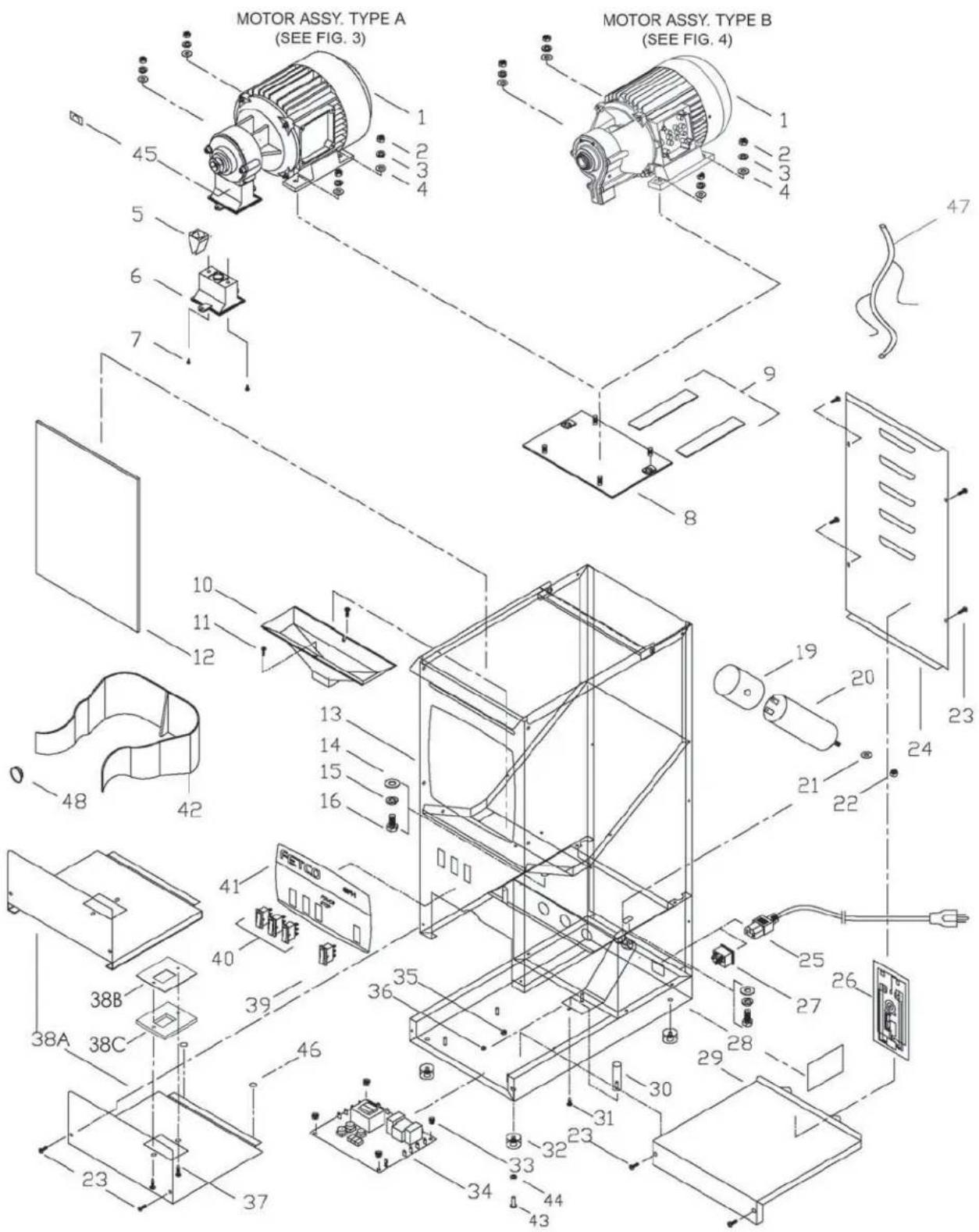
Parts List – Figure 1
| ITEM | QTY | PART.NO. | DESCRIPTION |
| 1 | 1 ---- MOTOR ASSEMBLY, TYPE A (SEE FIG. 3) | ||
| 1 ---- MOTOR ASSEMBLY, TYPE B (SEE FIG. 4) | |||
| 2 4 84024 NUT,HEX, 1/4"-20 SCREW SIZE | |||
| 3 4 83025 WASHER, 1/4" S.S. SPRING LOCK | |||
| 4 4 83034 WASHER 1/4" S.S., FLAT | |||
| 5 1 K056 COFFEE FLOW GUIDE (SET OF 2) (FOR TYPE A MOTORS ONLY) | |||
| 6 1 23086 COFFEE OUTLET, GR1/GR2 (FOR TYPE A MOTORS ONLY) | |||
| 7 2 82070 SCREW M3x8 PAN HD PHIL 18-8 S.S., M.S. (FOR TYPE A MOTORS ONLY) | |||
| 8 1 03185 PLATE, GRINDER MOTOR | |||
| 9 2 29015 TAPE, NOISE DAMPING | |||
| 10 1 23070 FUNNEL, HOPPER, GR-1 | |||
| 11 2 82059 SCREW, #8-32 X 3/8 TRUSS HD PHIL., MACHINE | |||
| 12 1 28002 WINDOW, GR-1 | |||
| 14 2 83031 WASHER 3/8", S.S. FLAT | |||
| 15 2 83032 WASHER 3/8" S.S. REG SPRING LOCK | |||
| 16 2 82069 SCREW, 3/8"-16x 3/4" LG, HEX HD. CAP. S.S. | |||
| 19 | 1 | 23094 CAP, CAPACITOR-220VAC (EXPORT VERSION ONLY) | |
| 23093 CAP, CAPACITOR - 120VAC | |||
| 20(TYPE AMOTORS) | 1 | 67001 CAP ACITOR, 120VAC VERSION, 40uF, 450VAC, 50-60Hz | |
| 67002 CAP ACITOR, 220VAC, 12uF, 450VAC, 50-60 Hz (EXPORT VERSION ONLY) | |||
| 67003 CAP ACITOR, 100VAC, 50uF, 250VAC, 50Hz (JAPAN VERSION ONLY)) | |||
| 20(TYPE BMOTORS) | 1 67004 CAPACITOR, 120VAC VERSION, 80uF, 450VAC, 50-60Hz | ||
| 1 67005 | CAPACITOR, 230VAC VERSION, 18uF, 450VAC, 50Hz (EXPORT VERSION ONLY) | ||
| 2 67004 CAPACITOR, 120VAC VERSION, 80uF, 450VAC, 50-60Hz (JAPAN VERSION - 2 REQD.) | |||
| 21 1 83033 WASHER, M8 REG S.S. SPRING LOCK | |||
| 22 1 84023 NUT, HEX, M8 S.S. | |||
| 23 8 82071 SCREW, #6-32 x 3/8" PAN HD PHIL w/ DOUBLE ACTION SPRING WSHR. | |||
| 24 1 01407 COVER REAR, GR-1 | |||
| 25 | 1 | 63038 CORD, AMERICAN, 6 FT LG | |
| 63041 CORD, EUROPEAN, 6.5FT LG | |||
| 63042 CORD, AUSTRALIAN, 6.5 FT LG | |||
| 63044 CORD, SOUTH AFRICA, 6.5 FT LG | |||
| 63043 CORD, ENGLAND, 6.5FT LG | |||
| 26 | 2 | 401204 WIRING DIAGRAM, UNIVERSAL, GR-1 | |
| 401205 WIRING DIAGRAM, 220/240 VAC, 50-60 HZ, 2.5 AMP | |||
| 27 1 65005 CONNECTOR, POWER INLET | |||
| 29 1 002178 WELDMENT, BASE COVER, GR1/2 | |||
| 30 1 21058 ROD, VIBRATION DAMPENING | |||
| 31 1 82032 SCREW, #8 x 1/2 S.S. T.S. PHILL TRUSS HD | |||
| 32 4 73030 FOOT, GRINDER | |||
| 33 4 29007 NUT, #4-40 NYLON FINGER | |||
| 34 | 1 | K032 CONTROL BOARD REPLACEMENT KIT, 120VAC | |
| K048 CONTROL BOARD REPLACEMENT KIT, 220VAC (EXPORT ONLY) | |||
| 35 1 84002 NUT, HEX, #8-32 S.S. | |||
| 36 1 83026 WASHER, #8 S.S. INTERNAL TOOTH LOCK | |||
| 37 | 2 | 82075 SCREW, #6-32 X 5/8 PHIL. TRUSS. S/M/S/ (TYPE A MOTORS ONLY) | |
| 82053 SCREW, # 6-32 X 1/2" TRUSS HD PHIL., MACHINE (TYPE B MOTORS ONLY) | |||
| 38A 1 | 01406 COVER, GRINDER SERVICE | ||
| K058 SERVICE GRINDING COVER WITH RAILS | |||
| 38B 1 03471 COVER GASKET, GRINDING OUTLET (TYPE B MOTORS ONLY) | |||
| 38C 1 24104 GASKET OUTLET (TYPE B MOTORS ONLY) | |||
| 39 1 58063 SWITCH, POWER ROCKER, RED 120VAC | |||
| 40 2 or 3 58061 SWITCH, START ROCKER, N/O 250V | |||
| 41 | 1 | 45074 OVERLAY, GR-1.2 | |
| 45075 OVERLAY, GR-1.3 | |||
| 42 1 23108 HOLDER, BREW BASKET, GR1/2 | |||
| 43 4 82097 SCREW, #10-32 x 0.625 S.S. PAN HEAD PHILLIPS | |||
| 44 4 83037 WASHER, #10 SPRING LOCKR | |||
| 45 1 44017 LABEL, GRAIN SIZE ADJUSTMENT, GR1/2 | |||
| 46 2 97033 BUMPER, 1/2" DIA. FLAT TOP, ADHESIVE BACKED, BLK | |||
| 47 | 1 | 402061 ELECTRICAL HARNESS, GR1.2 | |
| 402062 ELECTRICAL HARNESS, GR1.3 | |||
| 48 3 86053 PLUG, 0.812 DIA HOLE | |||
Figure 2 - GR-2.2 & GR-2.3
Grinders with serial numbers beginning with the number 2 or 3 were manufactured with Type A motors. Grinders with serial numbers beginning with the number 7 were manufactured with Type B motors.
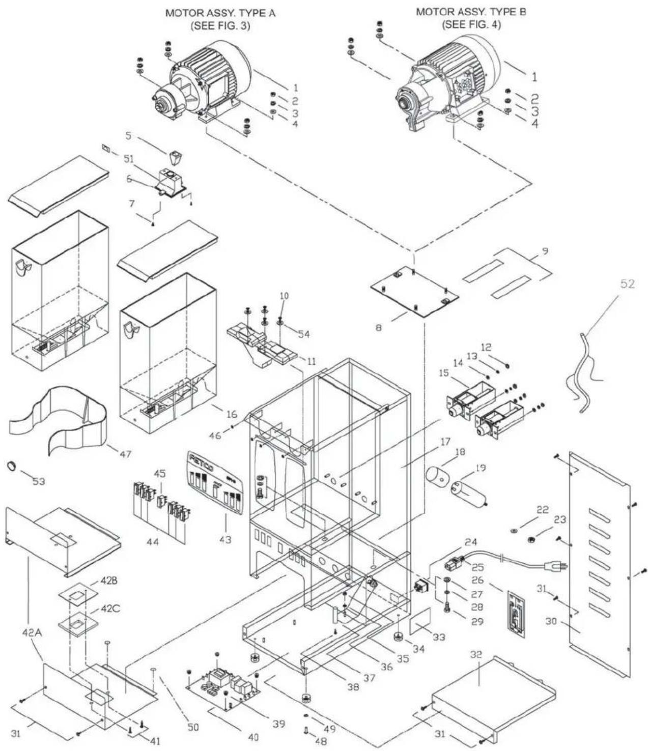
Parts List – Figure 2
| ITEM | QTY | PART NO. DESCRIPTION |
| 1 | 1 | ---- MOTOR ASSEMBLY, TYPE A (SEE FIG. 3) |
| ---- MOTOR ASSEMBLY, TYPE B (SEE FIG. 4) | ||
| 2 4 84024 NUT,HEK, 1/4"-20, 18-8 S.S | ||
| 3 4 83025 WASHER, 1/4" S.S. SPRING LOCK | ||
| 4 4 83034 WASHER, 1/4" S.S. FLAT | ||
| 5 1 K056 COFFEE FLOW GUIDE ($ET OF 2) (FOR TYPE A MOTORS ONLY) | ||
| 6 1 23086 COFFEE OUTLET, GR1/GR2 (FOR TYPE A MOTORS ONLY) | ||
| 7 2 82070 SCREW M3x8 PAN HD PHIL 18-8 S.S., M.S. (FOR TYPE A MOTORS ONLY) | ||
| 8 1 03185 PLATE,GRINDER MOTOR | ||
| 9 2 29015 TAPE, NOISE DAMPING | ||
| 10 4 82053 SCREW, #6-32x1/2" PHIL.SCREW TRUSS. HEAD M.S. | ||
| 11 2 23085 MANIFOLD | ||
| 12 4 84018 NUT, HEX,#10-32 MACHINE SCREW | ||
| 13 4 83037 WASHER, #10 REG.SPR.LOCK | ||
| 14 4 83036 WASHER, #10 FLAT | ||
| 15 | 2 | 102091 ASSEMBLY, SOLENOID, 120VAC |
| 102154 ASSEMBLY, SOLENOID, 230VAC (EXPORT VERSION ONLY) | ||
| 102155 ASSEMBLY, SOLENOID, 100VAC (JAPAN VERSION ONLY) | ||
| 16 2 A066 ASSEMBLY, HOPPER, GR2 (SEE FIG. 5) | ||
| 18 | 1 | 23093 CAP, CAPACITOR,120VAC |
| 23094 CAP, CAPACITOR, 220VAC (EXPORT VERSION ONLY) | ||
| 19(TYPE AMOTORS) | 1 | 67001 CAPACITOR, 120VAC VERSION, 40uF, 450VAC, 50-60Hz |
| 67002 CAPACITOR, 220VAC, 12uF, 450VAC, 50-60 Hz (EXPORT VERSION ONLY) | ||
| 67003 CAPACITOR,100VAC, 50uF, 250VAC, 50Hz (JAPAN VERSION ONLY)) | ||
| 19(TYPE BMOTORS) | 1 67004 | CAPACITOR, 120VAC VERSION, 80uF, 450VAC, 50-60Hz |
| 1 67005 | CAPACITOR, 230VAC VERSION, 18uF, 450VAC, 50Hz (EXPORT VERSION ONLY) | |
| 2 67004 CAPACITOR, | 120VAC VERSION, 80uF, 450VAC, 50-60Hz (JAPAN VERSION - 2 REQD.) | |
| 22 1 83033 WASHER, M8,SPRING LOCK | ||
| 23 1 84023 NUT, HEX, M8 , S.S. | ||
| 24 1 65005 CONNECTOR, POWER INLET | ||
| 25 | 1 | 63038 CORD, AMERICAN, 6FT |
| 63043 CORD, ENGLAND, 6.5FT | ||
| 63042 CORD, AUSTRALIAN, 6.5FT | ||
| 63041 CORD, EUROPEAN, 6.5FT | ||
| 63044 CORD, SOUTH AFRICA , 6.5FT | ||
| 26 2 401197 WIRING DIAGRAM, UNIVERSAL, GR-2 | ||
| 27 2 83031 WASHER, 3/8", S.S. FLAT | ||
| 28 2 83032 WASHER, 3/8" S.S.SPRING LOCK | ||
| 29 2 82069 SCREW, 3/8"-16x3/4"LG, HEX HD,CAP | ||
| 30 1 01410 COVER, REAR,GR-2 | ||
| 31 10 82071 SCREW, #6-32x3/8" PAN HD PHIL w/ DUAL ACTION | ||
| 32 1 002178 WELDMENT, BASE COVER, GR1/2 | ||
| 34 4 73030 FOOT, GRINDER | ||
| 35 1 84002 NUT, HEX, #8-32 S.S | ||
| 36 1 83026 WASHER, #8, S.S. INTERNAL TOOTH LOCK | ||
| 37 1 21058 ROD, VBRATION DAMPENING | ||
| 38 1 82032 SCREW, #8 X 1/2 TRUSS HD PH, SS SHEET MET | ||
| 39 4 29007 NUT, #4-40 NYLON FINGER | ||
| 40 | 1 | K032 CONTROL BOARD REPLACEMENT KIT, 120VAC |
| K048 CONTROL BOARD REPLACEMENT KIT, 220VAC (EXPORT ONLY) | ||
| 41 | 2 | 82075 SCREW, #6-32 X 5/8 PHIL. TRUSS. S/M/S/ (TYPE A MOTORS ONLY) |
| 82053 SCREW, # 6-32 X 1/2" TRUSS HD PHIL., MACHINE (TYPE B MOTORS ONLY) | ||
| 42A 1 | 01406 COVER, GRINDER SERVICE | |
| K058 SERVICE GRINDING COVER WITH RAILS | ||
| 42B 1 03471 COVER GASKET, GRINDING OUTLET (TYPE B MOTORS ONLY) | ||
| 42C 1 24104 GASKET OUTLET (TYPE B MOTORS ONLY) | ||
| 43 | 1 | 45073 OVERLAY, GR2.2 |
| 45072 OVERLAY, GR2.3 | ||
| 44 4 or 6 58061 SWITCH, START ROCKER N/O 250 VAC | ||
| 45 1 58063 SWITCH, POWER ROCKER,RED 120 VAC | ||
| 46 4 29010 FASTENER,9/32" HEAD DIA.x.165" LG, NYLON PUSH IN,(HOPPER GUIDE) | ||
| 47 1 23108 HOLDER, BREW BASKET,GR1/2 | ||
| 48 4 82097 SCREW, #10-32 X 0.625 S.S. PAN HEAD PHILLIPS | ||
| 49 4 83037 WASHER#10 SPRING LOCK | ||
| 50 2 97033 BUMPER,1/2" DIA. FLAT TOP, ADHESIVE BACKED , BLK | ||
| 51 1 44017 LABEL, GRAIN SIZE ADJUSTMENT, GR1/2 | ||
| 52 | 1 | 402063 ELECTRICAL HARNESS, GR-2.2 |
| 402064 ELECTRICAL HARNESS, GR2.3 | ||
| 53 3 86053 PLUG, 0.812 DIA. HOLE, | ||
| 54 4 24090 WASHER,18-8 SS,#6 SCREW SIZE,SEALING,NEOPRENE BONDED | ||
Figure 3 – GR-1 & GR-2 Motor Assy. – Type A
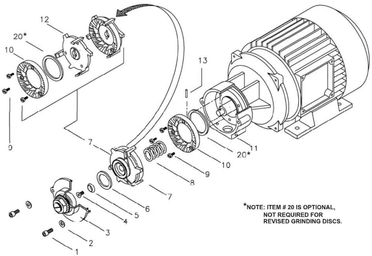
Parts List – Figure 3
| ITEM QTY PART NO. Description | |||
| 1 2 56 | 012 COVER | SCREWS | |
| 2 2 56 | 013 COVER | WASHERS | |
| 3 1 56 | 011 COVER | ASSEMBLY FOR GRINDING CHAMBER (includes K042 bearing assy.) | |
| (3) 1 K042 BEARING ASSEMBLY (includes bearing and adjustment shaft)(inside ITEM #3 – cover assembly) | |||
| 4 1 56 | 014 ROTOR | SCREW | |
| 5 1 56 | 015 ROTOR | WASHER | |
| 6 1 56 | 009 ROTATING DISC FLANGE | WASHER | |
| 7 NA | NA ROTOR | ASSEMBLY – NOT SOLD AS A COMPLETE ASSEMBLY | |
| 8 1 85 | 010 AUGER | SPRING | |
| 9 6 82 | 161 GRINDING DISC MOUNTING SCREWS | ||
| 10 1 14 | 006 GRINDING DISC, SET OF TWO | ||
| 11 | 1 | NOT AVAILABLE | GRINDING CHAMBER HOUSING ASSY. (SEE NOTE BELOW) |
| 12 1 56 | 008 ROTATING DISC FLANGE | (ALSO REQUIRES #20 – 24049 GRINDING RING) | |
| 13 1 87 | 018 MOTOR SHAFT PIN | ||
| 20 2 24 | 049 GRINDING RING, HDPE | ||
NOTE: Item # 11 - GRINDING CHAMBER HOUSING is no longer available. Grinders that require this part must be retrofitted to the Type B configuration shown in Fig. 4. The existing motor can still be used. To retrofit the grinding chamber, order part # K078 – GRINDING CHAMBER RETROFIT KIT.
The complete Type A MOTOR ASSEMBLY shown above is no longer available. Grinders that require a new motor must be retrofitted to the Type B motor shown in Fig. 4. To retrofit the entire motor assembly, order part # K077 – MOTOR ASSEMBLY RETROFIT KIT.
Figure 4 – GR-1 & GR-2 Motor Assy. – Type B
Part # RB1102.00037.00 - ASSEMBLY, MOTOR, .74HP, 120VAC, 60Hz
Part # 102377 - ASSEMBLY, MOTOR, .74HP, 230VAC, 50Hz (EXPORT ONLY)
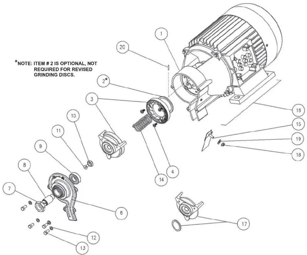
Parts List – Figure 4
| ITEM QTY PART NO. Description | ||
| 1 1 102362 ASSY, GRINDING HOUSING GR1/2 | ||
| 2 2 24049 RING, HDPE, GRINDING | ||
| 3 1 14006 GRINDING DISC, SET OF TWO | ||
| 4 3 82161 SCREW, M4 x 0.7 x 10mm LG., PAN HEAD, SLOTTED, 18-8 SS. | ||
| 6 6 56026 COVER, GRINDING CHAMBER HOUSING | ||
| 7 1 56020 NUT, M16x1 JAM | ||
| 8 & 9 1K042 BEARING ASSEMBLY (factory assembled - includes #8 adjustment shaft and #9 bearing) | ||
| 10 1 56015 WASHER, GR-1/GR-2 COUNTERSUNK | ||
| 11 1 56014 SCREW, M5 X 10, FLAT HEAD SLOTTED | ||
| 12 4 56013 WASHER, M5, SERRATED BELLEVILLE | ||
| 13 4 56012 SCREW, M5 X 12 METRIC, HEX HEAD | ||
| 14 1 85031 SPRING, GRINDER AUGER 6 MM PITCH | ||
| 15 1 002409 WELDMENT, COFFEE GUIDE, GR1/2 | ||
| 16 | 1 | 56027 MOTOR, Seg80-4A, 120V, 60Hz |
| 56028 MOTOR, Seg80-4A, 230V, 50Hz (EXPORT VERSION ONLY) | ||
| 17 1 102380 ASSEMBLY, ROTATING DISC FLANGE & WASHER, GR-1/2 | ||
| 18 1 84030 LOCKNUT, #8-32 SCREW SIZE, HEX THIN NYLON INSERT | ||
| 19 1 83051 WASHER, #8 SCREW SIZE, FLAT | ||
| 20 1 87018 MOTOR SHAFT PIN | ||
Figure 5 – GR-2.2 & GR-2.3 Hopper Assembly, Part # A066
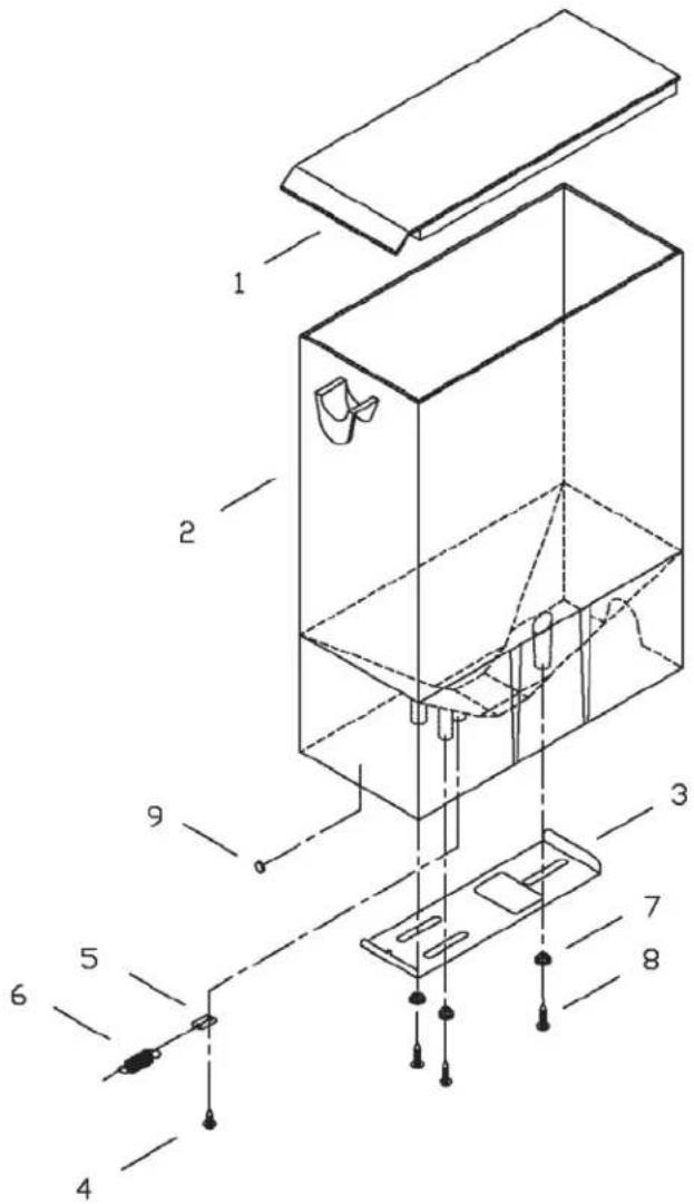
| ITEM QTY PART NO. Description | |
| 1 1 23081 LID, HOPPER, GR2 | |
| 2 1 23082 BODY, HOPPER, GR2 | |
| 3 1 03198 GUILLOTINE | |
| 4 1 82074 SCREW, #6 x 3/8 PHIL TRUSS HEAD SELF TAPING | |
| 5 1 03200 BRACKET, GUILLOTINE SPRING, GR2 | |
| 6 1 85012 SPRING, EXPANSION,3/8 x .026 x 1.375L 0.60 LBS/IN | |
| 7 3 29008 WASHER, SHOULDER,3/32L, .375A, 1/16B, .248C, .136D | |
| 8 3 82075 SCREW, #-6 x 5/8 TRUS S HEAD PHILLIPS SHEET META | |
| 9 1 97033 BUMPER, 1/2 DIA, FLAT TOP, ADHESIVE BACKED, BLK | |
Wiring Diagrams
GR-1
Effective August 2003
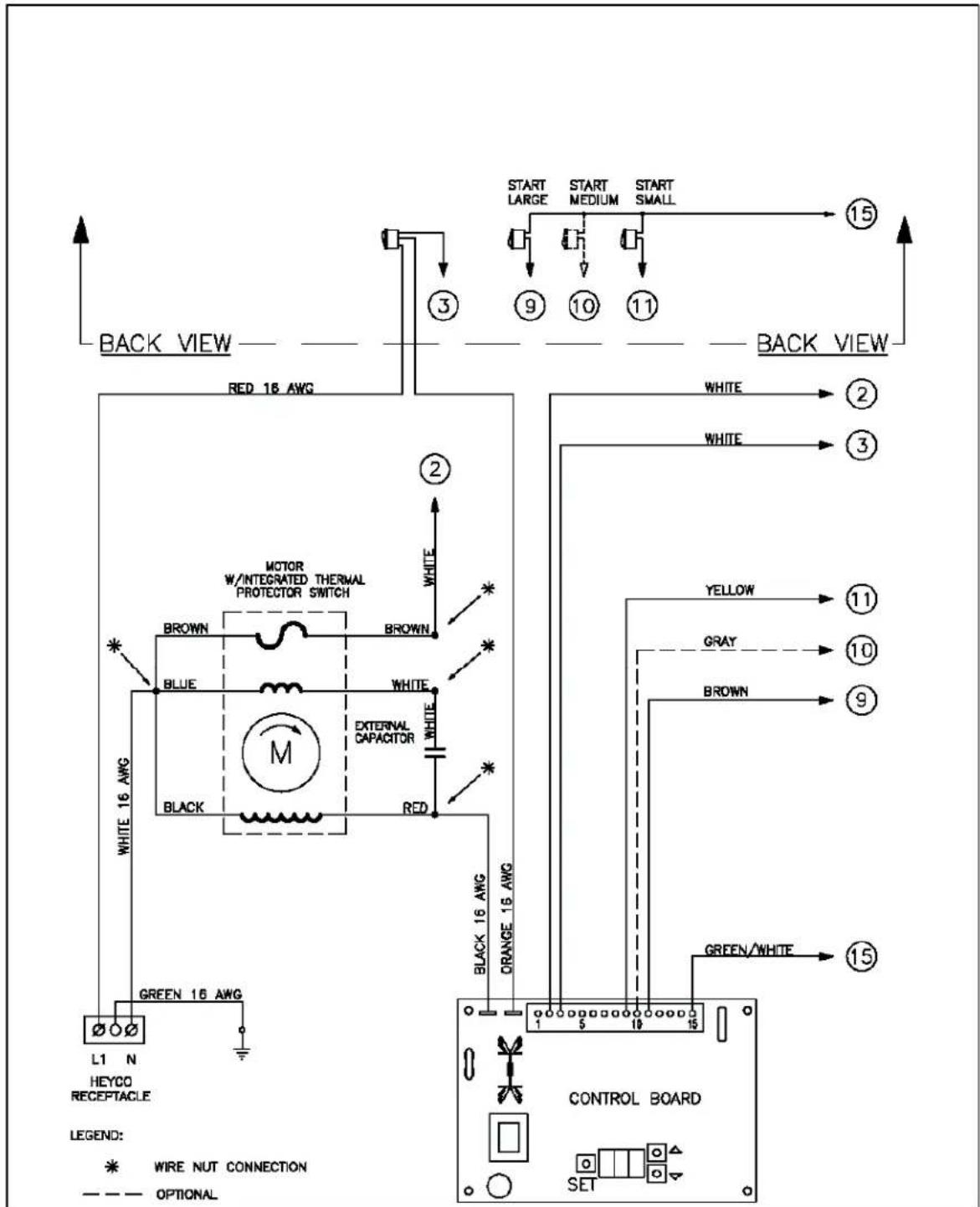

FOOD EQUIPMENT TECHNOLOGIES COMPANY, INC. 640 HEATHROW DRIVE. LINCOLNSHIRE . IL 60069. USA. PHONE: (800) 338-2699. (847) 821-1177 e-MAIL: techsupport@retco.com. http://www.fetco.com
| FETCO PRODUCT NO.GR-1(TRIAC) | DESCRIPTIONWIRING DIAGRAM, UNIVERSAL, GR-1 | WIRING DIAGRAM NO.401204-004 |
GR-2
Effective August 2003
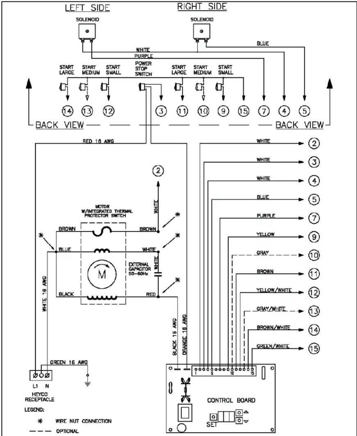
FETCO
FOOD EQUIPMENT TECHNOLOGIES COMPANY, INC.
640 HEATHROW DRME, UNCOLNSHIRE, IL, 60069, USA.
PHONE: (800) 536-2099. (847) 621-1(77) e-MAIL: becheupport@fetco.com. http://www.fetco.com
| FETCO PRODUCT NO.GR-2(TRIAC) | DESCRIPTIONWIRING DIAGRAM, UNIVERSAL, GR-2 | WIRING DIAGRAM NO.401197-008 |
Appendix A
Programming Instructions
For GR-1 & GR-2 Grinders manufactured prior to August 2003
Factory Settings:
- GR-1.2
Small batch switch: 13 seconds grind time.
Large batch switch: 26 seconds grind time.
- GR-1.3
Small batch switch: 13 seconds grind time.
Medium batch switch: 19.5 seconds grind time.
Large batch switch: 26 seconds grind time.
•GR-2.2
Small batch switch: 7 seconds grind time. Large batch switch: 13.5 seconds grind time.
(plus) 7 seconds additional after hopper closes.
- GR-2.3
Small batch switch: 7 seconds grind time. Medium batch switch: 13.5 seconds grind time. Large batch switch: 20 seconds grind time.
(plus) 7seconds additional after hopper closes.
Timer Adjustment:
- Remove the base panel
- Press and hold the set button for three to five seconds. The LED display will show SET. (While in the programming mode the grinder motor and guillotine solenoids are disabled.)
- Select the start switch you wish to reprogram, depress switch. The display will momentarily show the switch identification (S.I.D.).
Switch Identification:
| Model | Sm. Batch Left | Med. Batch Left | Lrg. Batch Left | Sm. Batch Right | Med. Batch Right | Lrg. Batch Right |
| GR-1.2 LH1 X LH3 X | XX | |||||
| GR-1.3 LH1 LH2 LH3 X XX | ||||||
| GR-2.2 LH1 X LH3 RH1 X RH3 | ||||||
| GR-2.3 LH1 LH2 LH3 RH1 RH2 RH3 |
• The display will then show the current timer setting for the switch you have selected.
- By pressing the up and down buttons you can now change your timer settings.
- The new programmed time will be automatically saved when you select the next start switch to be programmed.
- When all Start switches are programmed with the desired settings, press the set button. The display will then go blank and the control board will return to normal operation. Note: All changes will be lost if you do not press the set button.
Approximate grind times for medium size, average to dark roast beans.
| Batch Size | Typical Coffee Dosage | Timer setting | |
| Ounces | Grams | ||
| 12 Gallon | 2 – 4 oz. | 57 – 113 grams | 6.7 - 13.3 sec. |
| 2.5 – 3.0 Liters | 2 - 4.5 oz. | 57 – 128 grams | 6.7 - 15 sec. |
| 1 Gallon | 4 – 8 oz. | 113 – 227 grams | 13.3 - 27 sec. |
| 1.5 Gallons | 6 – 12 oz. | 170 – 340 grams | 20 – 40 sec. |
| 2 Gallons | 8 – 16 oz. | 227 – 454 grams | 27 – 53 sec. |
| 3 Gallons | 12 – 24 oz. | 340 – 680 grams | 40 - 80 sec. |
| 6 Gallons | 39 – 51 oz. | 1.1 – 1.44 kg. | 130 -170 sec. |
Grind times are affected by conditions of the coffee beans such as: age, size, oily or dry, and degree of roast.
- GR Series Coffee Grinders
- Contact Information
- Product Description/Features
- Specifications
- Installation
- Operating Instructions
- Cleaning:
- Service and Support
- Warranty
- Principles of Operation
- GR-1
- GR-2
- Grinder Foreign Object Protection
- Grind Adjustment
- Programming Instructions
- Software Version 1.2 and Above
- MOTOR DELAY
- DEFAULT SETTINGS
- Parts
- Wiring Diagrams
- FETCO
- Appendix A
- Factory Settings:
- Timer Adjustment:
Brand : Fetco
Model : GR-2.3
Category : Coffee maker