
PowerConnect M6348 - Network card DELL - Free user manual and instructions
Find the device manual for free PowerConnect M6348 DELL in PDF.


| Product Type | Managed Network Switch |
| Brand | Dell |
| Model | PowerConnect M6348 |
| Number of Ports | 48 |
| Port Type | 10/100/1000 Gigabit Ethernet |
| Layer Support | Layer 2 / Layer 3 (IPv4/IPv6) |
| Management | CLI, Telnet, SSH, Web (HTTP/HTTPS), SNMP, RMON |
| VLAN Support | 802.1Q VLAN, Private VLAN, Protocol VLAN, MAC-based VLAN |
| Security Features | 802.1X, ACL, DHCP Snooping, DAI, IP Source Guard, SSH, SSL |
| Quality of Service | CoS, DSCP mapping, traffic shaping, priority queuing |
| Spanning Tree | STP, RSTP, MSTP, PVST+ compatible |
| Routing Protocols | OSPF (v2/v3), RIP, static routing, VRRP, DVMRP, PIM |
| Link Aggregation | LACP, port channels (static/dynamic) |
| Data Center Features | DCBX, FIP Snooping, Priority Flow Control, iSCSI optimization |
| Power Supply | AC 100-240V, 50-60Hz, internal redundant (optional) |
| Dimensions (W x D x H) | 440 x 445 x 44 mm (1U rackmount) |
| Weight | Approximately 5.5 kg |
| Operating Temperature | 0°C to 45°C |
| Certifications | UL, CE, FCC, VCCI |
| Spare Parts / Repairability | Field-replaceable power supply and fan modules; SFP transceivers |
| Maintenance | CLI commands, backup/restore config, firmware upgrade via TFTP/HTTP |
| Manual Included | CLI Reference Guide (999 pages, PDF) |
Frequently Asked Questions - PowerConnect M6348 DELL
vlan 10), then assign ports using interface gigabitethernet and switchport access vlan 10.User questions about PowerConnect M6348 DELL
0 question about this device. Answer the ones you know or ask your own.
Ask a new question about this device
Download the instructions for your Network card in PDF format for free! Find your manual PowerConnect M6348 - DELL and take your electronic device back in hand. On this page are published all the documents necessary for the use of your device. PowerConnect M6348 by DELL.
USER MANUAL PowerConnect M6348 DELL
PCM6220, PCM6348, PCM8024,
PCM8024-k
CLI Reference Guide
Notes

NOTE: A NOTE indicates important information that helps you make better use of your computer.

CAUTION: A CAUTION indicates potential damage to hardware or loss of data if instructions are not followed.
Information in this publication is subject to change without notice.
© 2013 Dell Inc. All rights reserved.
Reproduction of these materials in any manner whatsoever without the written permission of Dell Inc. is strictly forbidden.
Trademarks used in this text: Dell™, the DELL logo, and PowerConnect™ are trademarks of Dell Inc. StrataXGS® is a registered trademark of Broadcom Corp. sFlow® is a registered trademark of InMon Corporation. Cisco® is a registered trademark of Cisco Systems, Inc. and/or its affiliates in the United States and certain other countries. Microsoft® and Windows® are registered trademarks of Microsoft Corporation in the United States and/or other countries.
Other trademarks and trade names may be used in this publication to refer to either the entities claiming the marks and names or their products. Dell Inc. disclaims any proprietary interest in trademarks and trade names other than its own.
Regulatory Model PCM6220, PCM6348, PCM8024, PCM8024-k
2013 - March Rev. A04
Contents
1 Command Groups 77
Introduction 77
Command Groups 77
Mode Types 81
Layer 2 Commands....83
Data Center Technology Commands. 118
Layer 3 Commands....120
Utility Commands 147
2 Using the CLI 169
Introduction 169
Entering and Editing CLI Commands. 169
CLI Command Modes 179
Starting the CLI. 192
Using CLI Functions and Tools. 200
3 Layer 2 Switching Commands ..... 241
4 AAA Commands.... 243
TACACS+ Accounting 244
Commands in this Chapter. 245
aaa authentication dot1x default 246
aaa authentication enable. 247
aaa authentication login. 249
aaa authorization 250
aaa authorization network default radius. 253
aaa ias-user username 253
aaa new-model 254
clear (IAS) 255
authorization 256
enable authentication 257
enable password 258
ip http authentication 259
ip https authentication. 260
login authentication 261
password (aaa IAS User Configuration). 262
password (Line Configuration) 263
password (User EXEC) 264
show aaa ias-users 265
show aaa statistics 266
show authentication methods. 267
show authorization methods 268
show users accounts 270
show users login-history 271
username. 272
username unlock 275
5 Administrative Profiles Commands .... 277
Overview 277
Commands in this Chapter. 278
admin-profile. 279
description (Administrative Profile Config) ..... 280
rule 281
show admin-profiles. 282
show admin-profiles brief. 283
show cli modes 284
6 ACL Commands 287
ACL Logging 287
Commands in this Chapter. 290
access-list 290
deny | permit (IP ACL) 292
deny | permit (Mac-Access-List-Configuration) ..... 294
ip access-group 296
mac access-group 297
mac access-list extended 298
mac access-list extended rename 299
service-acl input. 300
show service-acl interface 301
show ip access-lists. 302
show mac access-list 303
7 Address Table Commands.... 305
Commands in this Chapter. 306
clear mac address-table. 306
mac address-table aging-time 307
mac address-table multicast forbidden address ..... 308
mac address-table static vlan 309
port security 310
port security max 311
show mac address-table multicast ..... 312
show mac address-table 313
show mac address-table address 315
show mac address-table count 316
show mac address-table dynamic 317
show mac address-table interface 318
show mac address-table static 319
show mac address-table vlan 320
show ports security 321
show ports security addresses 323
8 Auto-VoIP Commands 325
Commands in this Chapter. 325
show switchport voice 326
switchport voice detect auto 328
9 CDP Interoperability Commands ..... 331
Commands in this Chapter. 331
clear isdp counters 331
clear isdp table 332
isdp advertise-v2. 332
isdp enable.... 333
isdp holdtime. 334
isdp timer 335
show isdp 335
show isdp entry 336
show isdp interface 338
show isdp neighbors. 339
show isdp traffic. 341
10 DHCP Layer 2 Relay Commands ..... 343
Commands in this Chapter. 343
dhcp l2relay (Global Configuration). 343
dhcp l2relay (Interface Configuration) 344
dhcp l2relay circuit-id 345
dhcp l2relay remote-id. 346
dhcp l2relay trust 346
dhcp l2relay vlan. 347
show dhcp l2relay all 348
show dhcp l2relay interface. 349
show dhcp l2relay stats interface. 350
show dhcp I2relay subscription interface ..... 351
show dhcp I2relay agent-option vlan 351
show dhcp I2relay vlan 353
show dhcp I2relay circuit-id vlan. 354
show dhcp I2relay remote-id vlan. 355
clear dhcp l2relay statistics interface 356
11 DHCP Management Interface Commands 357
Commands in this Chapter. 357
release dhcp 358
renew dhcp 359
debug dhcp packet 360
show dhcp lease. 361
12 DHCP Snooping Commands.... 365
Commands in this Chapter. 366
clear ip dhcp snooping binding 366
clear ip dhcp snooping statistics . . . . . . . . . . . 367
ip dhcp snooping. 367
ip dhcp snooping binding 368
ip dhcp snooping database 369
ip dhcp snooping database write-delay ..... 370
ip dhcp snooping limit.... 371
ip dhcp snooping log-invalid 372
ip dhcp snooping trust. 373
ip dhcp snooping verify mac-address....373
show ip dhcp snooping 374
show ip dhcp snooping binding....375
show ip dhcp snooping database 376
show ip dhcp snooping interfaces 377
show ip dhcp snooping statistics. 378
13 Dynamic ARP Inspection Commands .. 381
Commands in this Chapter. 381
arp access-list 381
clear ip arp inspection statistics ..... 382
ip arp inspection filter. 383
ip arp inspection limit 383
ip arp inspection trust 384
ip arp inspection validate 385
ip arp inspection vlan 386
permit ip host mac host 387
show arp access-list 388
show ip arp inspection 388
show ip arp inspection vlan 391
14 E-mail Alerting Commands 393
Commands in this Chapter. 393
logging email 394
logging email urgent 396
logging traps 397
logging email message-type to-addr 398
logging email from-addr 399
logging email message-type subject ..... 399
logging email logtime 400
logging email test message-type 401
show logging email statistics 402
clear logging email statistics 402
security. 403
mail-server ip-address | hostname ..... 404
port (Mail Server Configuration Mode) ..... 405
username (Mail Server Configuration Mode).....405
password (Mail Server Configuration Mode) ..... 406
show mail-server 407
15 Ethernet Configuration Commands .... 409
Commands in this Chapter. 410
clear counters 410
description 411
duplex 412
flowcontrol. 413
interface 414
interface range. 415
mtu 416
show interfaces advertise 417
show interfaces configuration 419
show interfaces counters 421
show interfaces description. 424
show interfaces detail. 425
show interfaces status 427
show statistics. 428
show statistics switchport 432
show storm-control 434
shutdown. 435
speed 435
storm-control broadcast. 437
storm-control multicast 438
storm-control unicast 439
switchport protected 440
switchport protected name 441
show switchport protected 442
16 Ethernet CFM Commands 443
Commands in this Chapter. 443
ethernet cfm domain. 444
service 445
ethernet cfm cc level 446
ethernet cfm mep level 447
ethernet cfm mep enable 448
ethernet cfm mep active. 449
ethernet cfm mep archive-hold-time 450
ethernet cfm mip level. 450
ping ethernet cfm 451
traceroute ethernet cfm 452
show ethernet cfm errors 454
show ethernet cfm domain 454
show ethernet cfm maintenance-points local ..... 455
show ethernet cfm maintenance-points remote ..... 457
show ethernet cfm statistics 458
debug cfm 459
17 GVRP Commands 463
Commands in this Chapter. 463
clear gvrp statistics 463
garp timer 464
gvrp enable (global) 465
gvrp enable (interface) 466
gvrp registration-forbid 467
gvrp vlan-creation-forbid 468
show gvrp configuration. 468
show gvrp error-statistics. 470
show gvrp statistics 471
18 IGMP Snooping Commands....473
Commands in this Chapter. 474
ip igmp snooping. 474
show ip igmp snooping 476
show ip igmp snooping groups 477
show ip igmp snooping mrouter. 478
ip igmp snooping vlan immediate-leave ..... 479
ip igmp snooping vlan groupmembership-interval . . . 480
ip igmp snooping vlan last-member-query-interval . . 481
ip igmp snooping vlan mcrtrexpiretime. 482
ip igmp snooping report-suppression....483
ip igmp snooping unregistered floodall. 484
ip igmp snooping vlan mrouter 484
19 IGMP Snooping Querier Commands ... 487
Commands in this Chapter. 487
ip igmp snooping querier 487
ip igmp snooping querier election participate ..... 489
ip igmp snooping querier query-interval ..... 490
ip igmp snooping querier timer expiry 490
ip igmp snooping querier version ..... 491
show ip igmp snooping querier 492
20 IP Addressing Commands ..... 495
Commands in this Chapter. 495
clear host 496
clear ip address-conflict-detect 496
interface out-of-band 497
ip address (Out-of-Band) 498
ip address-conflict-detect run 499
ip address dhcp (Interface Config) 500
ip default-gateway. 501
ip domain-lookup 502
ip domain-name 503
ip host 504
ip name-server. 504
ipv6 address (Interface Config) 505
ipv6 address dhcp 507
ipv6 enable (Interface Config)....508
show hosts 508
show ip address-conflict 509
show ip helper-address....511
show ipv6 dhcp interface out-of-band statistics ..... 512
show ipv6 interface out-of-band 513
21 IPv6 Access List Commands ..... 515
Commands in this Chapter. 515
deny | permit (IPv6 ACL) 516
ipv6 access-list 518
ipv6 access-list rename 519
ipv6 traffic-filter 520
show ipv6 access-lists 521
22 IPv6 MLD Snooping Commands..... 525
Commands in this Chapter. 525
ipv6 mld snooping vlan groupmembership-interval .. 526
ipv6 mld snooping vlan immediate-leave ..... 526
ipv6 mld snooping listener-message-suppression . . . 527
ipv6 mld snooping vlan last-listener-query-interval .. 528
ipv6 mld snooping vlan mcrtexpiretime....529
ipv6 mld snooping vlan mrouter. 530
ipv6 mld snooping (Global) 530
show ipv6 mld snooping....531
show ipv6 mld snooping groups. 533
show ipv6 mld snooping mrouter 534
23 IPv6 MLD Snooping Querier Commands 537
Commands in this Chapter. 537
ipv6 mld snooping querier. 538
ipv6 mld snooping querier (VLAN mode) ..... 538
ipv6 mld snooping querier address ..... 539
ipv6 mld snooping querier election participate ..... 540
ipv6 mld snooping querier query-interval. 541
ipv6 mld snooping querier timer expiry . . . . . . . . 541
show ipv6 mld snooping querier 542
24 IP Source Guard Commands ..... 545
Commands in this Chapter. 545
ip verify source 545
ip verify source port-security 546
ip verify binding 547
show ip verify interface 547
show ip verify source interface ..... 548
show ip source binding 548
25 iSCSI Optimization Commands ..... 551
Commands in this Chapter. 552
iscsi aging time 552
iscsi cos 553
iscsi enable 555
iscsi target port 556
show iscsi 558
show iscsi sessions 559
26 Link Dependency Commands ..... 563
Commands in this Chapter. 563
action. 563
link-dependency group 564
add gigabitethernet 565
add tengigabitethernet 565
add port-channel. 566
depends-on. 567
show link-dependency 568
27 LLDP Commands 571
Commands in this Chapter. 572
clear lldp remote-data. 572
clear lldp statistics 573
dcb enable 574
Ildp med 574
Ildp med confignotification 575
Commands in this Chapter. 600
mvr 600
mvr group 601
mvr mode. 602
mvr querytime 602
mvr vlan 604
mvr immediate 604
mvr type 605
mvr vlan group 607
show mvr. 608
show mvr members 609
show mvr interface 611
show mvr traffic 612
29 Port Aggregator Commands ..... 615
add interface.... 615
duplex 616
lacp auto 617
lapp off 618
lapc static 618
minimum active uplinks 619
mtu disable. 620
negotiation 621
no lacp 621
port-aggregator group. 622
show mac address-table 623
speed 624
vlan. 624
30 Port Channel Commands 627
Static LAGS 627
VLANs and LAGs 628
LAG Thresholds 628
Port Channels 629
LAG Hashing 629
Enhanced LAG Hashing 630
Manual Aggregation of LAGs 630
Manual Aggregation of LAGs 631
Flexible Assignment of Ports to LAGs. 631
Commands in this Chapter. 631
channel-group 631
interface port-channel....632
interface range port-channel 633
hashing-mode 634
lacp port-priority. 635
lacp system-priority 636
lacp timeout 636
port-channel local-preference 637
port-channel min-links 638
show interfaces port-channel....639
show lacp 640
show statistics port-channel 642
31 Port Monitor Commands 647
Commands in this Chapter. 647
monitor session 648
show monitor session 649
32 QoS Commands 651
Access Control Lists 651
Layer 2 ACLs 652
Layer 3/4 IPv4 ACLs 652
Class of Service (CoS) 652
Queue Mapping 653
PCM6220 Limitations. 654
Commands in this Chapter. 654
assign-queue. 655
class 656
class-map 657
class-map rename 657
classofservice dot1p-mapping 658
classofservice ip-dscp-mapping 659
classofservice trust 663
conform-color 664
cos-queue min-bandwidth 666
show diffserv service interface 705
show diffserv service interface port-channel ..... 706
show diffserv service brief 707
show interfaces cos-queue 708
show interfaces random-detect 710
show policy-map 711
show policy-map interface 711
show service-policy 713
traffic-shape 714
33 RADIUS Commands 717
Commands in this Chapter. 720
aaa accounting dot1x default start-stop ..... 721
accounting 723
acct-port 724
auth-port 725
deadtime 725
debug aaa accounting 726
key 727
msgauth 728
name (RADIUS server) 728
primary 730
priority 730
radius-server attribute 4 . . . . . . . . . . . . . . . . . . . . . . 731
radius-server deadtime 732
radius-server host 733
radius-server key 734
radius-server retransmit. 735
radius-server source-ip 736
radius-server timeout 736
retransmit 737
show aaa servers 738
show accounting methods 740
show radius statistics 741
source-ip 745
timeout 746
usage. 746
34 Spanning Tree Commands....749
Commands in this Chapter. 750
clear spanning-tree detected-protocols 751
exit (mst) 752
instance (mst) 752
name (mst) 754
revision (mst). 755
show spanning-tree 755
show spanning-tree summary 759
spanning-tree 760
spanning-tree auto-portfast 761
spanning-tree bpdu flooding 762
spanning-tree bpdu-protection 762
spanning-tree cost. 763
spanning-tree disable 765
spanning-tree forward-time 765
spanning-tree guard. 766
spanning-tree loopguard 767
spanning-tree max-age 768
spanning-tree max-hops. 769
spanning-tree mode 769
spanning-tree mst configuration 770
spanning-tree mst cost 771
spanning-tree mst port-priority 772
spanning-tree mst priority 773
spanning-tree portfast. 774
spanning-tree portfast bpdufilter default ..... 775
spanning-tree portfast default. 776
spanning-tree port-priority 777
spanning-tree priority 777
spanning-tree tcnguard 778
spanning-tree transmit hold-count 779
35 TACACS+ Commands 781
Commands in this Chapter. 781
key 782
port. 782
priority 783
show tacacs 784
tacacs-server host 785
tacacs-server key 786
tacacs-server timeout 787
timeout 787
36 UDLD Commands 789
Detecting Unidirectional Links on a Device Port . . . 789
Processing UDLD Traffic from Neighbors. ..... 790
UDLD in Normal-mode. 790
UDLD in Aggressive-mode. 790
Commands in this Chapter. 791
udId enable (Global Config) 791
udld reset 792
udld message time. 793
udld timeout interval. 793
udld enable (Interface Config). 794
udld port 795
show udd 796
debug udld 797
37 VLAN Commands 799
Double VLAN Mode 799
Independent VLAN Learning. 800
Protocol Based VLANs. 800
IP Subnet Based VLANs 801
MAC-Based VLANs 801
Private VLAN Commands 801
Commands in this Chapter. 804
dvlan-tunnel ethertype. 805
interface vlan 806
interface range vlan 807
mode dvlan-tunnel 808
name (VLAN Configuration) 809
protocol group 810
protocol vlan group 811
protocol vlan group all. 812
show dvlan-tunnel 813
show dvlan-tunnel interface 814
show interfaces switchport 815
show port protocol. 819
show vlan 820
show vlan association mac 821
show vlan association subnet 822
switchport access vlan 823
switchport general forbidden vlan 824
switchport general acceptable-frame-type tagged-only 825
switchport general allowed vlan 826
switchport general ingress-filtering disable ..... 827
switchport general pvid. 828
switchport mode. 829
switchport trunk 830
vlan. 832
vlan (Global Config) 833
vlan association mac 834
vlan association subnet 835
vlan database 835
vlan makestatic 836
vlan protocol group 837
vlan protocol group add protocol 838
vlan protocol group name 839
vlan protocol group remove. 839
switchport private-vlan 840
switchport mode private-vlan 841
private-vlan 842
show vlan private-vlan 844
38 Voice VLAN Commands 847
Commands in this Chapter. 848
voice vlan 848
voice vlan (Interface) 848
voice vlan data priority 850
show voice vlan 850
39 802.1x Commands 853
Local 802.1X Authentication Server ..... 853
MAC Authentication Bypass. 854
Guest VLAN 855
802.1x Monitor Mode 855
RADIUS-based Dynamic VLAN Assignment ..... 856
Commands in this Chapter. 856
dot1x dynamic-vlan enable 857
dot1x initialize 858
dot1x mac-auth-bypass 858
dot1x max-req 859
dot1x max-users 860
dot1x port-control 861
dot1x re-authenticate 862
dot1x reauthentication. 863
dot1x system-auth-control 863
dot1x system-auth-control monitor 864
dot1x timeout guest-vlan-period 865
dot1x timeout quiet-period 866
dot1x timeout re-authperiod....867
dot1x timeout server-timeout 867
dot1x timeout supp-timeout 868
dot1x timeout tx-period 869
show dot1x....870
show dot1x authentication-history ..... 871
show dot1x clients. 873
show dot1x interface 876
show dot1x interface statistics 877
show dot1x users 879
clear dot1x authentication-history 880
dot1x guest-vlan 881
dot1x unauth-vlan 882
show dot1x advanced 882
40 Data Center Technology Commands . . . 885
41 Data Center Bridging Commands ..... 887
NOTE: Data Center Bridging Exchange Protocol . . . . 887
Interoperability with IEEE DCBX 891
Port Roles 891
Commands in this Chapter. 895
Data Center Bridging Capability Exchange Commands 896
datacenter-bridging 896
Ildp dcbx version 897
lldp tlv-select dcbxp (dcb enable) 898
Ildp dcbx port-role....899
show lldp tlv-select 901
show lldp dcbx. 902
Enhanced Transmission Selection (ETS) Commands . . 907
NOTE: classofservice traffic-class-group. 907
traffic-class-group max-bandwidth....908
traffic-class-group min-bandwidth 910
traffic-class-group strict 911
traffic-class-group weight 913
show classofservice traffic-class-group ..... 914
show interfaces traffic-class-group 915
42 FIP Snooping Commands....919
Setting Up FIP Snooping. 919
Commands in this Chapter. 920
feature fip-snooping 921
fip-snooping enable 922
fip-snooping fc-map 923
fip-snooping port-mode 924
show fip-snooping 925
show fip-snooping enode 927
show fip-snooping fcf 929
show fip-snooping sessions. 932
show fip-snooping statistics 938
show fip-snooping vlan 945
clear fip-snooping statistics. 946
43 Priority Flow Control Commands ..... 949
Commands in this Chapter. 950
priority-flow-control mode 950
priority-flow-control priority 952
clear priority-flow-control statistics 953
show interfaces priority-flow-control 953
44 Layer 3 Commands 957
45 ARP Commands 959
ARP Aging 960
Commands in this Chapter. 960
arp 960
arp cachesize 961
arp dynamicrenew....962
arp purge. 963
arp resptime 964
arp retries 965
arp timeout. 965
clear arp-cache 966
clear arp-cache management 967
ip local-proxy-arp 968
ip proxy-arp 968
show arp 969
46 DHCP Server and Relay Agent Commands 971
Commands in this Chapter. 972
ip dhcp pool 972
bootfile 975
clear ip dhcp binding 976
clear ip dhcp conflict 976
client-identifier 977
client-name 978
default-router 979
dns-server (IP DHCP Pool Config) 980
domain-name (IP DHCP Pool Config) ..... 981
hardware-address 981
host. 982
ip dhcp bootp automatic. 983
ip dhcp conflict logging 984
ip dhcp excluded-address. 985
ip dhcp ping packets. 986
lease 987
netbios-name-server. 988
netbios-node-type 989
network 990
next-server. 990
option. 991
service dhcp 995
sntp 996
show ip dhcp binding 997
show ip dhcp conflict 998
show ip dhcp global configuration 998
show ip dhcp pool 999
show ip dhcp server statistics 1000
47 DHCPv6 Commands 1003
clear ipv6 dhcp. 1003
dns-server (IPv6 DHCP Pool Config) 1004
domain-name (IPv6 DHCP Pool Config) ..... 1004
ipv6 dhcp pool 1005
ipv6 dhcp relay. 1006
ipv6 dhcp server 1007
prefix-delegation 1008
service dhcpv6. 1010
show ipv6 dhcp 1011
show ipv6 dhcp binding 1011
show ipv6 dhcp interface (User EXEC) ..... 1012
show ipv6 dhcp interface (Privileged EXEC) ..... 1014
show ipv6 dhcp pool 1018
show ipv6 dhcp statistics 1018
48 DVMRP Commands 1021
Commands in this Chapter.... 1021
ip dvmrp 1021
ip dvmrp metric 1022
show ip dvmrp 1023
show ip dvmrp interface. 1024
show ip dvmrp neighbor....1024
show ip dvmrp nexthop 1025
show ip dvmrp prune 1026
show ip dvmrp route ..... 1027
49 GMRP Commands 1029
Commands in this Chapter. 1030
gmrp enable 1030
show gmrp configuration 1031
50 IGMP Commands 1033
Commands in this Chapter. 1034
ip igmp 1034
ip igmp last-member-query-count 1035
ip igmp last-member-query-interval ..... 1036
ip igmp query-interval 1037
ip igmp query-max-response-time 1038
ip igmp robustness. 1038
ip igmp startup-query-count. 1039
ip igmp startup-query-interval. 1040
ip igmp version. 1041
show ip igmp. 1041
show ip igmp groups. 1042
show ip igmp interface 1043
show ip igmp membership 1045
show ip igmp interface stats 1045
ip igmp router-alert-check 1046
51 IGMP Proxy Commands.... 1049
Commands in this Chapter. 1049
ip igmp-proxy 1049
ip igmp-proxy reset-status 1050
ip igmp-proxy unsolicit-rprt-interval ..... 1051
show ip igmp-proxy 1052
show ip igmp-proxy interface ..... 1053
show ip igmp-proxy groups....1054
show ip igmp-proxy groups detail 1054
52 IP Helper/DHCP Relay Commands.... 1057
Commands in this Chapter.... 1059
bootpdhcprelay maxhopcount....1059
bootpdhcprelay minwaittime 1060
clear ip helper statistics. 1061
ip dhcp relay information check 1061
ip dhcp relay information check-reply ..... 1062
ip dhcp relay information option 1063
ip dhcp relay information option-insert. 1064
ip helper-address (global configuration) ..... 1065
ip helper-address (interface configuration). ..... 1067
ip helper enable 1069
show ip helper-address 1069
show ip dhcp relay. 1071
show ip helper statistics 1072
53 IP Routing Commands 1075
Static Routes/ECMP Static Routes 1075
Static Reject Routes....1076
Default Routes 1076
Commands in this Chapter. 1076
encapsulation 1077
ip address 1077
ip mtu. 1079
ip netdirbcast 1080
ip route....1081
ip route default. 1082
ip route distance 1083
ip routing. 1084
show ip brief....1085
show ip interface 1085
show ip protocols 1088
show ip route 1092
show ip route configured 1094
show ip route connected 1095
show ip route preferences 1096
show ip route summary 1097
show ip traffic 1098
show ip vlan 1101
show routing heap summary 1101
54 IPv6 Routing Commands ..... 1105
IPv6 Limitations & Restrictions 1105
Commands in this Chapter. 1105
clear ipv6 neighbors....1106
clear ipv6 statistics 1107
ipv6 address 1108
ipv6 enable.... 1109
ipv6 hop-limit 1110
ipv6 host 1110
ipv6 mld last-member-query-count ..... 1111
ipv6 mld last-member-query-interval ..... 1112
ipv6 mld-proxy 1112
ipv6 mld-proxy reset-status 1113
ipv6 mld-proxy unsolicit-rprt-interval....1114
ipv6 mld query-interval 1114
ipv6 mld query-max-response-time ..... 1115
ipv6 mld router 1116
ipv6 mtu 1117
ipv6 nd dad attempts. 1118
ipv6 nd managed-config-flag 1119
ipv6 nd ns-interval 1119
ipv6 nd other-config-flag 1120
ipv6 nd prefix. 1121
ipv6 nd ra-interval 1122
ipv6 nd ra-lifetime 1123
ipv6 nd reachable-time 1124
ipv6 nd suppress-ra 1125
ipv6 route. 1126
ipv6 route distance. 1127
ipv6 unicast-routing 1128
ping ipv6 1129
ping ipv6 interface.... 1130
show ipv6 brief. 1131
show ipv6 interface 1132
show ipv6 interface management statistics ..... 1134
show ipv6 mld groups 1135
show ipv6 mld interface ..... 1138
show ipv6 mld-proxy. 1141
show ipv6 mld-proxy groups 1142
show ipv6 mld-proxy groups detail 1144
show ipv6 mld-proxy interface 1145
show ipv6 mld traffic 1147
show ipv6 neighbors.... 1148
show ipv6 route 1149
show ipv6 route preferences 1151
show ipv6 route summary 1152
show ipv6 traffic 1153
show ipv6 vlan 1155
traceroute ipv6. 1156
55 Loopback Interface Commands..... 1159
Commands in this Chapter. 1159
interface loopback. 1159
show interfaces loopback 1160
56 Multicast Commands.... 1163
Commands in this Chapter. 1164
ip mcast boundary 1164
ip mroute.... 1165
ip multicast. 1166
ip multicast ttl-threshold 1167
ip pim. 1168
ip pim bsr-border. 1169
ip pim bsr-candidate.... 1170
ip pim dense 1171
ip pim dr-priority 1171
ip pim hello-interval 1172
ip pim join-prune-interval....1173
ip pim rp-address 1174
ip pim rp-candidate 1175
ip pim sparse 1176
ip pim ssm 1177
show ip multicast 1177
show ip mcast boundary. 1178
show ip multicast interface ..... 1179
show ip mcast mroute ..... 1180
show ip mcast mroute group 1181
show ip mcast mroute source ..... 1182
show ip mcast mroute static 1182
show ip pim 1183
show ip pim bsr-router. 1184
show ip pim interface 1185
show ip pim neighbor 1187
show ip pim rp hash 1189
show ip pim rp mapping ..... 1190
57 IPv6 Multicast Commands.... 1193
ipv6 pim (Global config) 1193
ipv6 pim (VLAN Interface config) 1194
ipv6 pim bsr-border 1195
ipv6 pim bsr-candidate 1195
ipv6 pim dense 1196
ipv6 pim dr-priority. 1197
ipv6 pim hello-interval ..... 1198
ipv6 pim join-prune-interval. 1198
ipv6 pim register-rate-limit 1199
ipv6 pim register-threshold 1200
ipv6 pim rp-address 1201
ipv6 pim rp-candidate 1201
ipv6 pim sparse (Global config) 1202
ipv6 pim spt-threshold 1203
ipv6 pim ssm 1204
show ipv6 pim 1204
show ipv6 pim bsr 1206
show ipv6 pim bsr-router 1206
show ipv6 pim interface.... 1208
show ipv6 pim neighbor ..... 1208
show ipv6 pim rphash 1209
show ipv6 pim rp mapping. 1210
58 OSPF Commands 1213
Route Preferences 1214
OSPF Equal Cost Multipath (ECMP) ..... 1214
Forwarding of OSPF Opaque LSAs Enabled by Default 1215
Passive Interfaces 1215
Graceful Restart 1216
Commands in this Chapter. 1216
area default-cost (Router OSPF). 1217
clear ip ospf stub-router....1240
compatiblerfc1583. 1241
default-information originate (Router OSPF Configuration) 1242
default-metric 1243
distance ospf. 1244
distribute-list out 1245
enable 1246
exit-overflow-interval.... 1247
external-lsdb-limit. 1247
ip ospf area. 1248
ip ospf authentication 1249
ip ospf cost. 1250
ip ospf database-filter all out ..... 1251
ip ospf dead-interval 1251
ip ospf hello-interval. 1252
ip ospf network 1254
ip ospf priority 1255
ip ospf retransmit-interval. 1255
ip ospf transmit-delay 1256
log adjacency-changes 1257
max-metric router-lsa 1258
maximum-paths 1259
network area. 1260
nsf 1261
nsf helper 1263
nsf helper strict-lsa-checking. 1263
nsf restart-interval....1264
passive-interface default 1265
passive-interface 1266
redistribute. 1267
router-id 1268
router ospf 1269
show ip ospf 1269
show ip ospf interface brief. 1288
show ip ospf interface stats ..... 1289
show ip ospf neighbor....1290
show ip ospf range. 1293
show ip ospf statistics. 1295
show ip ospf stub table 1296
show ip ospf traffic 1297
show ip ospf virtual-link. 1300
show ip ospf virtual-links brief ..... 1301
timers pacing flood 1302
timers pacing Isa-group. 1302
timers spf. 1303
59 OSPFv3 Commands 1305
area default-cost (Router OSPFv3) 1306
area stub no-summary 1315
area virtual-link 1316
area virtual-link dead-interval 1318
area virtual-link hello-interval 1318
area virtual-link retransmit-interval 1319
area virtual-link transmit-delay 1320
default-information originate (Router OSPFv3 Configuration) 1321
default-metric 1322
distance ospf. 1323
enable 1324
exit-overflow-interval 1324
external-lsdb-limit. 1325
ipv6 ospf 1326
ipv6 ospf area 1327
ipv6 ospf cost 1328
ipv6 ospf dead-interval 1328
ipv6 ospf hello-interval 1329
ipv6 ospf mtu-ignore. 1330
ipv6 ospf network 1331
ipv6 ospf priority 1332
ipv6 ospf retransmit-interval 1333
ipv6 ospf transmit-delay 1333
ipv6 router ospf 1334
maximum-paths 1335
nsf 1335
nsf helper 1336
nsf helper strict-lsa-checking. 1337
nsf restart-interval....1338
passive-interface 1339
passive-interface default 1340
redistribute. 1340
router-id 1341
show ipv6 ospf 1342
show ipv6 ospf abr. 1346
show ipv6 ospf area 1347
show ipv6 ospf asbr 1348
show ipv6 ospf border-routers. 1348
show ipv6 ospf database 1349
show ipv6 ospf database database-summary ..... 1352
show ipv6 ospf interface 1353
show ipv6 ospf interface brief. 1355
show ipv6 ospf interface stats....1355
show ipv6 ospf interface vlan 1357
show ipv6 ospf neighbor. 1358
show ipv6 ospf range 1360
show ipv6 ospf stub table 1361
show ipv6 ospf virtual-links....1361
show ipv6 ospf virtual-link brief ..... 1362
60 Router Discovery Protocol Commands 1365
Commands in this Chapter.... 1365
ip irdp 1365
ip irdp address.... 1367
ip irdp holdtime 1368
ip irdp maxadvertinterval 1369
ip irdp minadvertinterval 1370
ip irdp multicast 1371
ip irdp preference 1371
show ip irdp 1372
61 Routing Information Protocol Commands 1375
Commands in this Chapter. 1375
auto-summary 1375
default-information originate (Router RIP Configuration) 1376
default-metric 1377
distance rip 1378
distribute-list out 1378
enable 1379
hostroutesaccept 1380
ip rip 1381
ip rip authentication....1381
ip rip receive version 1382
ip rip send version 1383
redistribute. 1384
router rip 1385
show ip rip 1386
show ip rip interface. 1387
show ip rip interface brief. 1388
split-horizon 1389
62 Tunnel Interface Commands ..... 1391
Commands in this Chapter. 1391
interface tunnel 1392
show interfaces tunnel 1392
tunnel destination 1393
tunnel mode ipv6ip. 1394
tunnel source 1395
63 Virtual Router Redundancy Protocol Commands 1397
Pingable VRRP Interface 1397
VRRP Route/Interface Tracking....1398
Interface Tracking 1399
Route Tracking 1399
Commands in this Chapter. 1399
ip vrrp 1400
vrrp accept-mode 1400
vrrp authentication 1401
vrrp description 1402
vrrp ip 1403
vrrp mode 1404
vrrp preempt 1405
vrrp priority. 1406
vrrp timers advertise....1407
vrrp timers learn 1408
vrrp track interface 1409
vrrp track ip route 1410
show vrrp 1412
show vrrp interface 1414
show vrrp interface brief 1416
show vrrp interface stats 1417
ip vrrp accept-mode ..... 1418
show ip vrrp interface ..... 1419
64 Utility Commands.... 1421
65 Auto-Install Commands 1423
Commands in this Chapter. 1424
boot auto-copy-sw....1424
boot auto-copy-sw allow-downgrade ..... 1425
boot host autoreboot. 1426
boot host autosave.... 1427
boot host dhcp 1427
boot host retrycount 1428
show auto-copy-sw 1429
show boot 1430
66 Captive Portal Commands ..... 1433
Commands in this Chapter. 1433
authentication timeout. 1435
captive-portal 1435
enable 1436
http port 1437
https port 1437
show captive-portal 1438
show captive-portal status 1439
block 1440
configuration. 1441
enable 1441
group 1442
interface 1443
locale. 1443
name (Captive Portal) 1444
protocol 1445
redirect. 1445
redirect-url. 1446
session-timeout 1446
verification. 1447
captive-portal client deauthenticate 1448
show captive-portal client status ..... 1448
show captive-portal configuration client status . . . 1449
show captive-portal interface client status ..... 1450
show captive-portal interface configuration status . 1452
clear captive-portal users ..... 1453
no user 1453
show captive-portal user 1454
user group 1455
user-logout. 1456
user name 1457
user password 1457
user session-timeout 1458
show captive-portal configuration 1459
show captive-portal configuration interface ..... 1460
show captive-portal configuration locales ..... 1461
show captive-portal configuration status. ..... 1461
user group 1463
user group moveusers.... 1463
user group name 1464
67 CLI Macro Commands ..... 1465
Commands in this Chapter. 1466
macro name 1466
macro global apply 1467
macro global trace. 1468
macro global description ..... 1469
macro apply 1470
macro trace 1471
macro description 1472
show parser macro 1472
68 Clock Commands 1475
Real-time Clock 1475
Simple Network Time Protocol 1475
Commands in this Chapter. 1476
show sntp configuration. 1476
show sntp server.... 1477
show sntp status.... 1479
sntp authenticate 1480
sntp authentication-key 1481
sntp broadcast client enable 1482
sntp client poll timer.... 1482
sntp server 1483
sntp trusted-key 1484
sntp unicast client enable 1485
clock timezone hours-offset 1486
no clock timezone 1486
clock summer-time recurring 1487
clock summer-time date....1488
no clock summer-time....1489
show clock. 1490
69 Command Line Configuration Scripting Commands 1493
Commands in this Chapter. 1493
script apply. 1493
script delete 1494
script list 1495
script show. 1495
script validate 1496
70 Configuration and Image File Commands 1499
File System Commands 1499
Command Line Interface Scripting ..... 1499
Commands in this Chapter. 1499
boot system 1500
clear config 1501
copy 1501
delete. 1507
delete backup-config 1508
delete backup-image 1508
delete startup-config 1509
dir 1509
erase 1510
filedescr 1511
rename 1512
show backup-config.... 1513
show bootvar. 1514
show running-config 1515
show startup-config 1516
update bootcode 1518
write 1518
71 Denial of Service Commands ..... 1521
Commands in this Chapter. 1522
dos-control firstfrag 1523
dos-control icmp....1523
dos-control l4port 1524
dos-control sipdip 1525
dos-control tcpflag 1526
dos-control tcpfrag 1526
ip icmp echo-reply....1527
ip icmp error-interval 1528
ip unreachables 1529
ip redirects.... 1529
ipv6 icmp error-interval 1530
ipv6 unreachables 1531
show dos-control 1531
72 Line Commands 1533
exec-timeout. 1533
history 1534
history size 1535
line 1535
show line. 1537
speed 1538
73 Management ACL Commands ..... 1539
Commands in this Chapter. 1539
deny (management) 1540
management access-class 1541
management access-list 1542
permit (management) 1543
show management access-class ..... 1545
show management access-list 1546
74 Mode Commands.... 1547
configure terminal 1547
do....1547
75 Password Management Commands .. 1551
Configurable Minimum Password Length. ..... 1551
Password History 1551
Password Aging 1551
User Lockout 1551
Password Strength 1552
Commands in this Chapter. 1553
passwords aging. 1554
passwords history 1554
passwords lock-out 1555
passwords min-length 1556
passwords strength-check 1557
passwords strength minimum uppercase-letters. . . 1558
passwords strength minimum lowercase-letters . . 1559
passwords strength minimum numeric-characters . 1560
passwords strength minimum special-characters . . 1561
passwords strength max-limit consecutive-characters 1561
passwords strength max-limit repeated-characters. 1562
passwords strength minimum character-classes . . 1563
passwords strength exclude-keyword ..... 1564
enable password encrypted....1565
show passwords configuration ..... 1566
show passwords result 1568
76 PHY Diagnostics Commands ..... 1569
show copper-ports tdr 1569
show fiber-ports optical-transceiver ..... 1570
test copper-port tdr 1571
77 RMON Commands 1573
Commands in this Chapter. 1573
rmon alarm 1573
rmon collection history 1576
rmon event 1577
show rmon alarm 1578
show rmon alarms 1580
show rmon collection history ..... 1581
show rmon events 1582
show rmon history 1583
show rmon log 1587
show rmon statistics. 1588
78 SDM Templates Commands.... 1591
Commands in this Chapter. 1591
sdm prefer 1591
show sdm prefer 1593
79 Serviceability Tracing Packet Commands 1597
Commands in this Chapter. 1597
debug arp 1598
debug auto-voip 1599
debug clear 1599
debug console 1600
debug dot1x 1600
debug igmpsnooping. 1601
debug ip acl 1602
debug ip dvmrp. 1602
debug ip igmp 1603
debug ip mcache. 1604
debug ip pimdm packet 1605
debug ip pimsm packet 1606
debug ip vrrp.... 1606
debug ipv6 dhcp 1607
debug ipv6 mcache 1608
debug ipv6 mld. 1608
debug ipv6 pimdm 1609
debug ipv6 pimsm 1610
debug isdp 1611
debug lacp 1612
debug mldsnooping 1612
debug ospf 1613
debug ospfv3. 1614
debug ping 1614
debug rip. 1615
debug sflow 1616
debug spanning-tree. 1616
debug vrrp 1617
show debugging 1617
80 Sflow Commands.... 1619
Commands in this Chapter. 1619
sflow destination 1619
sflow polling 1621
sflow polling (Interface Mode) 1622
sflow sampling. 1623
sflow sampling (Interface Mode) ..... 1624
show sflow agent 1625
show sflow destination 1626
show sflow polling 1627
show sflow sampling 1628
81 SNMP Commands 1631
Commands in this Chapter. 1631
show snmp 1631
show snmp engineID 1633
show snmp filters 1633
show snmp group 1635
show snmp user 1636
show snmp views 1637
show trapflags 1638
snmp-server community ..... 1640
snmp-server community-group 1642
snmp-server contact. 1643
snmp-server enable traps 1644
snmp-server engineID local. 1646
snmp-server filter 1647
snmp-server group. 1649
snmp-server host 1650
snmp-server location 1652
snmp-server user 1653
snmp-server view 1654
snmp-server v3-host 1656
82 SSH Commands 1659
Commands in this Chapter. 1659
crypto key generate dsa. 1659
crypto key generate rsa 1660
crypto key pubkey-chain ssh 1661
crypto key zeroize pubkey-chain 1662
crypto key zeroize {rsa|dsa} 1663
ip ssh port 1663
ip ssh pubkey-auth. 1664
ip ssh server 1665
key-string 1665
no crypto certificate 1667
show crypto key mypubkey 1668
show crypto key pubkey-chain ssh 1669
show ip ssh 1670
user-key 1671
83 Syslog Commands 1673
CLI Logged to Local File and Syslog Server. . . . . . 1673
Commands in this Chapter. 1674
clear logging. 1675
clear logging file. 1675
description (Logging) 1676
level 1677
logging cli-command 1677
logging 1679
logging audit 1681
logging buffered 1682
logging console 1683
logging facility. 1684
logging file.... 1685
logging monitor 1686
logging on 1687
logging snmp. 1688
logging web-session 1688
port. 1689
show logging. 1690
show logging file 1691
show syslog-servers....1692
terminal monitor 1693
84 System Management Commands .... 1695
asset-tag 1695
banner exec 1696
banner login 1697
banner motd 1698
banner motd acknowledge 1699
clear checkpoint statistics 1702
clear counters stack-ports 1702
cut-through mode 1703
exec-banner 1704
hardware profile portmode 1704
hostname. 1705
initiate failover. 1706
ip address 1707
ip address none 1708
ip address {dhcp/bootp} 1708
login-banner 1709
member. 1710
motd-banner 1711
nsf 1711
ping. 1712
reload 1714
set description.... 1715
slot 1715
show banner 1717
show boot-version. 1718
show checkpoint statistics 1719
show cut-through mode 1720
show hardware profile 1720
show interfaces advanced firmware ..... 1721
show ip interface out-of-band. 1722
show memory cpu 1723
show nsf 1724
show power-usage-history 1725
show process cpu 1726
show sessions 1728
show slot. 1730
show supported cardtype 1731
show supported switchtype 1733
show switch 1735
show system 1743
show system power 1746
show system temperature 1747
show tech-support....1749
show users.... 1751
show version. 1752
stack 1753
stack-port 1754
standby 1755
switch renumber. 1756
telnet 1757
traceroute 1759
85 Telnet Server Commands.... 1763
Telnet Client Behaviors 1763
Commands in this Chapter. 1766
ip telnet server disable 1766
ip telnet port 1767
show ip telnet 1767
86 Terminal Length Commands ..... 1769
terminal length. 1769
87 Time Ranges Commands ..... 1771
time-range 1771
absolute 1772
periodic 1773
show time-range. 1775
88 User Interface Commands.... 1779
enable 1779
end 1780
exit 1780
mode simple 1781
quit 1782
89 Web Server Commands 1783
Web Sessions 1783
Commands in this Chapter. 1784
common-name 1784
country 1785
crypto certificate generate 1786
crypto certificate import. 1787
crypto certificate request 1788
duration 1789
ip http port 1790
ip http server 1791
ip http secure-certificate 1791
ip http secure-port 1792
ip http secure-server. 1793
key-generate 1794
location. 1794
organization-unit 1795
show crypto certificate mycertificate....1796
show ip http server status 1797
show ip http server secure status ..... 1797
state 1799
A Appendix A: List of Commands ..... 1801
Command Groups
Introduction
The Command Line Interface (CLI) is a network management application operated through an ASCII terminal without the use of a Graphic User Interface (GUI) driven software application. By directly entering commands, the user has greater configuration flexibility. The CLI is a basic command-line interpreter similar to the UNIX C shell.
A switch can be configured and maintained by entering commands from the CLI, which is based solely on textual input and output with commands being entered by a terminal keyboard and the output displayed as text via a terminal monitor. The CLI can be accessed from a console terminal connected to an EIA/TIA-232 port or through a Telnet/SSH session.
This guide describes how the CLI is structured, describes the command syntax, and describes the command functionality.
This guide also provides information for configuring the PowerConnect switch, details the procedures, and provides configuration examples. Basic installation configuration is described in the User's Guide and must be completed before using this document.
Command Groups
The system commands can be broken down into four sets of functional groups: Layer 2, Data Center Technology, Layer 3, and Utility.
Table 1-1. System Command Groups
| Command Group Description | |
| Layer 2 Commands | |
| AAA | Configures connection security including authorization and passwords. |
| Administrative Profiles Commands | Group commands into a profile and assign a profile to a user upon authentication. |
| Command Group Description | |
| Administrative Profiles | Configures and displays ACL information. |
| Address Table | Configures bridging address tables. |
| Auto-VoIP | Configures Auto VoIP for IP phones on a switch. |
| CDP Interoperability | Configures Cisco® Discovery Protocol (CDP). |
| DHCP L2 Relay | Enables the Layer 2 DHCP Relay agent for an interface. |
| DHCP Management Interface | Configures DHCP snooping and whether an interface is trusted for filtering. |
| Dynamic ARP Inspection | Configures for rejection of invalid and malicious ARP packets. |
| Ethernet Configuration | Configures all port configuration options for example ports, storm control, port speed and auto-negotiation. |
| Ethernet CFM | Configures and displays GVRP configuration and information. |
| IGMP Snooping | Configures IGMP snooping and displays IGMP configuration and IGMP information. |
| IGMP Snooping Querier | Configures IGMP Snooping Querier and displays IGMP Snooping Querier information. |
| IP Addressing | Configures and manages IP addresses on the switch. |
| IPv6 ACL | Configures and displays ACL information for IPv6. |
| IPv6 MLD Snooping | Configures IPv6 MLD Snooping. |
| IPv6 MLD Snooping Querier | Configures IPv6 Snooping Querier and displays IPv6 Snooping Querier information. |
| iSCSI Optimization | Configures special QoS treatment for traffic between iSCSI initiators and target systems. |
| Link Dependency | Configures and displays link dependency information. |
| LLDP | Configures and displays LLDP information. |
| Port Aggregator | Provides server administrators the ability to map internal ports to external ports easily. |
| Port Channel | Configures and displays Port channel information. |
| Port Monitor | Monitors activity on specific target ports. |
| Command Group Description | |
| QoS | Configures and displays QoS information. |
| Radius | Configures and displays RADIUS information. |
| Spanning Tree | Configures and reports on Spanning Tree protocol. |
| TACACS+ | Configures and displays TACACS+ information. |
| VLAN | Configures VLANs and displays VLAN information. |
| 802.1x | Configures and displays commands related to 802.1x security protocol. |
| Data Center Technology Commands | |
| Data Center Bridging Commands | Data Center Bridging Exchange Protocol (DCBX) is used by DCB devices to exchange configuration information with directly connected peers. The protocol is also used to detect misconfiguration of the peer DCB devices and, optionally, for configuration of peer DCB devices. |
| FIP Snooping Commands | FCoE Initialization Protocol (FIP) is used to perform the functions of FC_BB_E device discovery, initialization and maintenance. FIP snooping is a frame inspection method used by FIP Snooping Bridges to monitor FIP frames and apply policies based upon the L2 header information in those frames, following recommendations in Annex C of FC_BB_5 Rev 2.00 |
| Priority Flow Control Commands | Provides priority-based flow control that can pause (inhibit transmission of) individual priorities within a single physical link. |
| Layer 3 Commands | |
| ARP (IPv4) | Manages Address Resolution Protocol functions. |
| DHCP Server and Relay Agent (IPv4) | Manages DHCP/BOOTP operations on the system. |
| DHCPv6 | Configures IPv6 DHCP functions. |
| DVMRP (Mcast) Configures | DVMRP operations. |
| IGMP (Mcast) Configures | IGMP operations. |
| IGMP Proxy (Mcast) Manages | IGMP Proxy on the system. |
| IP Helper/DHCP Relay | Configures relay of UDP packets. |
| IP Routing (IPv4) Configures | IP routing and addressing. |
| IPv6 Multicast | Manages IPv6 Multicasting on the system. |
| IPv6 Routing | Configures IPv6 routing and addressing. |
| Loopback Interface (IPv6) | Manages Loopback configurations. |
| Multicast (Mcast) Manages | Multicasting on the system. |
| OSPF (IPv4) Manages shortest path operations. | |
| OSPFv3 (IPv6) Manages | IPv6 shortest path operations. |
| Router Discovery Protocol (IPv4) | Manages router discovery operations. |
| Routing Information Protocol (IPv4) | Configures RIP activities. |
| Tunnel Interfa(IPv6) Managing tunneling operations. | |
| Virtual Router Redundancy (IPv4) | Controls virtual LAN routing. |
| Virtual Router Redundancy (IPv4) | Manages router redundancy on the system. |
| Utility Commands | |
| Auto-Install | Automatically configures switch when a configuration file is not found. |
| Captive Portal | Blocks clients from accessing network until user verification is established. |
| Clock | Configures the system clock. |
| Command Line Configuration Scripting | Manages the switch configuration files. |
| Denial of Service | Provides several Denial of Service options. |
| Line | Configures the console, SSH, and remote Telnet connection. |
| Management ACL | Configures and displays management access-list information. |
| Password Management | Provides password management. |
| PHY Diagnostics | Diagnoses and displays the interface status. |
| RMON | Can be configured through the CLI and displays RMON information. |
| Serviceability Tracing | Controls display of debug output to serial port or telnet console. |
| sFlow | Configures sFlow monitoring. |
| SNMP | Configures SNMP communities, traps and displays SNMP information. |
| SSII | Configures SSII authentication. |
| Syslog | Manages and displays syslog messages. |
| System Management | Configures the switch clock, name and authorized users. |
| Telnet Serve r | Configures Telnet service on the switch and displays Telnet information. |
| User Interface | Describes user commands used for entering CLI commands. |
| Web Server | Configures web-based access to the switch. |
Mode Types
The tables on the following pages use these abbreviations for Command Mode names.
- AAA — IAS User Configuration
- APC — Administrative Profile Configuration
• ARPA — ARP ACL Configuration - CC — Crypto Configuration
• CP — Captive Portal Configuration
• C P I — C a p t i v e P o r t a l I n s t .
- CMC — Class-Map Configuration
- DP — IP DHCP Pool Configuration
• GC — Global Configuration
- IC — Interface Configuration (reached via interface vlan xxx command)
• IP — IP Access List Configuration
- IR — Interface Range
• K C — K e y C h a i n
• K E — K e y
• L — Logging
- LC — Line Configuration
• LD — Link Dependency
• MA — Management Access-level
- MC — MST Configuration
• MDC — Maintenance Domain Configuration
- ML — MAC-List Configuration
• MSC — Mail Server Configuration
• M T — M A C - a c l
• OG — OSPFv2 Global Configuration
• PA — Port Aggregator
• PE — Privileged EXEC
• PM — Policy Map Configuration
• PCGC — Policy Map Global Configuration
• PCMC — Policy Class Map Configuration
• R — R a d i u s
- RIP — Router RIP Configuration
- RC — Router Configuration
- ROSPF — Router Open Shortest Path First
- ROSV3 — Router Open Shortest Path First Version 3
• SG — Stack Global Configuration
- S P — S S H P u b l i c K e y
- S K — S S H P u b l i c K e y - c h a i n
• TC — TACACS Configuration - TRC — Time Range Configuration
- UE — User EXEC
- VC — VLAN Configuration (reached via vlan database command)
• v6ACL — IPv6 Access List Configuration
• v6CMC — IPv6 Class-Map Configuration
• v6DP — IPv6 DHCP Pool Configuration
Layer 2 Commands
AAA
| Command | Description Mode | a |
| aaa authentication dot1x default | Specifies an authentication method for 802.1x clients. | GC |
| aaa authentication enable | Defines authentication method lists for accessing higher privilege levels. | GC |
| aaa authentication login | Defines login authentication. GC | |
| aaa authorization network ddefault radius | Enables the switch to accept VLAN assignment by the RADIUS server. | GC |
| aaa ias-user username | Configures IAS users and their attributes. Also changes the mode to aa user config mode. | GC |
| clear (IAS) aaa ias-users Deletes all IAS users. PE | ||
| enable authentication | Specifies the authentication method list when accessing a higher privilege level from a remote tclnct or console. | LC |
| enable password | Sets a local password to control access to the normal level. | GC |
| ip http authentication | Specifies authentication methods for http. GC | |
| ip https authentication | Specifies authentication methods for https. GC | |
| login authentication | Specifies the login authentication method list for a remote telnet or console. | LC |
| password (aaa IAS User Configuration) | Configures a password for a user. AAA | |
| password (Line Configuration) | Specifies a password on a line. LC | |
| password (User EXEC) | Specifies a user password UE | |
| show aaa ias-users | Displays configured IAS users and their attributes. | PE |
| show authentication methods | Shows information about authentication methods. | PE |
| show users accounts | Displays information about the local user database. | PE |
| show users login-history | Displays information about login histories of users. | PE |
| username | Establishes a username-based authentication system. Optionally allows the specification of an Administrative Profile for a local user. | GC |
| username unlock | Transfers local user passwords between devices without having to know the passwords. | GC |
a. For the meaning of each Mode abbreviation, see Mode Types on page 81
Administrative Profiles
| Command Description Mode | a | |
| admin-profile | Creates an administrative profile. GC | |
| description (Administrative Profile Config) | Adds a description to an administrative profile. APC | |
| rule | Adds a rule to an administrative profile. APC | |
| show admin-profiles | Displays the administrative profiles. PE | |
| show admin-profiles brief | Lists the names of the administrative profiles defined on the switch. | PE |
| show cli modes | Lists the names of all the CLI modes. PE | |
| show users | Shows which administrative profiles have been assigned to local user accounts and to show which profiles are active for logged-in users. | PE |
| username | Optionally allows the specification of an Administrative Profile for a local user. | GC |
a. For the meaning of each Mode abbreviation, see Mode Types on page 81.
ACL
| Command Description Mode | a | |
| access-list | Creates an Access Control List (ACL) that is identified by the parameter accesslistnumber. | GC |
| deny | permit (IP ACL) | The deny command denies traffic if the conditions defined in the deny statement are matched. The permit command allows traffic if the conditions defined in the permit statement are matched. | ML |
| ip access-group | Attaches a specified access-control list to an interface. | GC or IC |
| mac access-group | Attaches a specific MAC Access Control List (ACL) to an interface in the in-bound direction. | GC or IC |
| mac access-list extended | Creates the MAC Access Control List (ACL) identified by the name parameter. | GC |
| mac access-list extended rename | Renames the existing MAC Access Control List (ACL) name. | GC |
| service-acl input Blocks Link | Local Protocol Filtering (LLPF) protocol(s) on a given port. | IC |
| show service-acl interface | Displays the status of LLPF rules configured on a particular port or on all the ports. | PE |
| show ip access-lists | Displays an Access Control List (ACL) and all of the rules that are defined for the ACL. | PE |
| show mac access-list | Displays a MAC access list and all of the rules that are defined for the ACL. | PE |
Address Table
| Command Description Mode | a | |
| clear mac address-table | Removcs any learned entries from the forwarding database. | PE |
| mac address-table aging-time | Sets the address table aging time. CC | |
| mac address-table multicast forbidden address | Forbids adding a specific multicast address to specific ports. | IC |
| mac address-table static vlan | Registers MAC-layer multicast addresses to the bridge forwarding table, and adds static ports to the group. | IC |
| mac address-table static vlan | Adds a static MAC-layer station source address to the bridge table. | IC |
| port security | Disables new address learning on an interface. IC | |
| port security max | Configures the maximum addresses that can be learned on the port while the port is in port security mode. | IC |
| show mac address-table | Displays dynamically created entries in the bridge-forwarding database. | PE |
| show mac address-table address | Displays all entries in the bridge-forwarding database for the specified MAC address. | UE or PE |
| show mac address-table count | Displays the number of addresses present in the Forwarding Database. | PE |
| show mac address-table dynamic | Displays all entries in the bridge-forwarding database. | UE or PE |
| show mac address-table interface | Displays the mac forwarding table entries for a specific interface. | UE or PE |
| show mac address-table multicast | Displays Multicast MAC address table information. | PE |
| show mac address-table static | Displays statically created entries in the bridge-forwarding database. | PE |
| show mac address-table vlan | Displays all entries in the bridge-forwarding database for the specified VLAN. | UE or PE |
| show ports security | Displays the port-lock status. PE | |
| show ports security addresses | Displays current dynamic addresses in locked ports. | PE |
a. For the meaning of each Mode abbreviation, see Mode Types on page 81.
Auto-VoIP
| Command Description Mode | a | |
| switchport voice detect auto | Enables the VoIP Profile on all the interfaces of the switch. | GC or IC |
| show switchport voice | Displays the status of auto-voip on an interface or all interfaces. | PE |
a. For the meaning of each Mode abbreviation, see Mode Types on page 81.
CDP Interoperability
| Command Description Mode | a | |
| clear isdp counters | Clears the ISDP counters. PE | |
| clear isdp table | Clears entries in the ISDP table. PE | |
| isdp advertise-v2 | Enables the sending of ISDP version 2 packets from the device. | GC |
| isdp enable | Enables ISDP on the switch. GC or | IC |
| isdp holdtime | Configures the hold time for ISDP packets that the switch transmits. | GC |
| isdp timer | Sets period of time between sending new ISDP packets. | GC |
| show isdp | Displays global ISDP settings. PE | |
| show isdp interface | Displays ISDP settings for the specified interface. | PE |
| show isdp entry | Displays ISDP entries. PE | |
| show isdp neighbors | Displays the list of neighboring devices. PE | |
| show isdp traffic | Displays ISDP statistics. PE |
a. For the meaning of each Mode abbreviation, see Mode Types on page 81.
DHCP L2 Relay
| Command Description Mode | a | |
| dhcp l2relay (Global Configuration) | Enables the Layer 2 DHCP Relay agent for an interface or globally. | GC or IC |
| dhcp l2relay circuit-id | Enables user to set the DHCP Option 82 Circuit ID for a VLAN. | GC |
| dhcp l2relay remote-id | Enables user to set the DHCP Option 82 Remote ID for a VLAN. | GC |
| dhcp l2relay vlan | Enables the L2 DHCP Relay agent for a set of VLANs. | GC |
| dhcp l2relay trust | Configures an interface to trust a received DIICP Option 82. | IC |
a. For the meaning of each Mode abbreviation, see Mode Types on page 81.
DHCP Management Interface
| Command Description Mode | a | |
| relcase dhcp | Forces the DIICPv4 client to release a leased address. | PE |
| renew dhcp | Forces the DHCP client to immediately renew an IPv4 address lane. | PE |
| debug dhcp packet | Displays debug information about DHCPv4 client activities and traces DHCP v4 packets to and from the local DHCPv4 client. | PE |
| show dhcp lease | Displays IPv4 addresses leased from a DHCP server. | PE |
a. For the meaning of each Mode abbreviation, see Mode Types on page 81.
DHCP Snooping
| Command Description Mode | a | |
| clear ip dhcp snooping binding | Clears all DHCP Snooping entries. PE | |
| clear ip dhcp snooping statistics | Clears all DHCP Snooping statistics. PE | |
| ip dhcp snooping | Enables DHCP snooping globally or on a specific VLAN. | GC or IC |
| ip dhcp snooping binding | Configures a static DHCP Snooping binding. GC | |
| ip dhcp snooping database | Configures the persistent location of the DHCP snooping database. | GC |
| ip dhcp snooping database write-delay | Configures the interval in seconds at which the DHCP Snooping database will be stored in persistent storage. | GC |
| ip dhcp snooping limit | Controls the maximum rate of DHCP messages. | IC |
| ip dhcp snooping log-invalid | Enables logging of DHCP messages filtered by the DIICP Snooping application. | IC |
| ip dhcp snooping trust | Configure a port as trusted for DHCP snooping. | IC |
| ip dhcp snooping verify mac-address | Enables the verification of the source MAC address with the client MAC address in the received DIICP message. | GC |
| show ip dhcp snooping | Displays the DHCP snooping global and per port configuration. | PE |
| show ip dhcp snooping binding | Displays the DIICP snooping binding entries. PE | |
| show ip dhcp snooping database | Displays the DIICP snooping configuration related to the database persistence. | PE |
| show ip dhcp snooping interfaces | Displays the DHCP Snooping status of the interfaces. | PE |
| show ip dhcp snooping statistics | Displays the DHCP snooping filtration statistics. | PE |
a. For the meaning of each Mode abbreviation, see Mode Types on page 81.
Dynamic ARP Inspection
| Command Description Mode | a | |
| arp access-list | Creates an ARP ACL. GC | |
| clear ip arp inspection statistics | Resets the statistics for Dynamic ARP Inspection on all VLANs. | PE |
| ip arp inspection filter | Configures the ARP ACL to be used for a single VLAN or a range of VLANs to filter invalid ARP packets. | GC |
| ip arp inspection limit | Configures the rate limit and burst interval values for an interfacc. | IC |
| ip arp inspection trust | Configures an interface as trusted for Dynamic ARP Inspection. | IC |
| ip arp inspection validate | Enables additional validation checks like source MAC address validation, destination MAC address validation or IP address validation on the received ARP packets. | GC |
| ip arp inspection vlan | Enables Dynamic ARP Inspection on a single VLAN or a range of VLANs. | GC |
| permit ip host mac host | Configures a rule for a valid IP address and MAC address combination used in ARP packet validation. | ARPA |
| show arp access-list | Displays the configured ARP ACLs with the rules. | PE |
| show ip arp inspection | Displays the Dynamic ARP Inspection configuration. | PE |
| show ip arp inspection interfaces | Displays the Dynamic ARP Inspection configuration on all the DAI enabled interfaces. | PE |
| show ip arp inspection vlan | Displays the Dynamic ARP Inspection configuration on all the VLANs in the given VLAN range. | PE |
a. For the meaning of each Mode abbreviation, see Mode Types on page 81.
E-mail Alerting
| Command Description Mode | a | |
| logging email | Enables e-mail alerting and sets the lowest severity level for which log messages are e-mailed. | GC |
| logging email urgent | Sets the lowest severity level at which log messages are e-mailed in an urgent manner. | GC |
| logging traps | Sets the lowest severity level at which SNMP traps are logged. | GC |
| logging email message-type to-addr | Configures the To address field of the c-mail. GC | GC |
| logging email from-addr | Configures the From address of the c-mail. GC | |
| logging email message-type subject | Configures the subject. GC | |
| logging email logtime | Configures the value of how frequently the queued messages are sent. | GC |
| logging email test message-type | Tests whether or not an c-mail is being sent to an SMTP server. | GC |
| show logging email statistics | Displays information on how many c-mails are sent, how many e-mails failed, when the last e-mail was sent, how long it has been since the last e-mail was sent, how long it has been since the c-mail changed to disabled mode. | PE |
| clear logging email statistics | Clears the e-mail alerting statistics. GC | |
| security | Sets the e-mail alerting security protocol. MSC | |
| mail-server ip-address | hostname | Configures the SMTP server IP address and changes the mode to Mail Server Configuration Mode. | GC |
| port (Mail Server Configuration Mode) | Configures the TCP port to use for communication with the SMTP servers. | MSC |
| username (Mail Server Configuration Mode) | Configures the username required by the authentication. | MSC |
| password (Mail Server Configuration Mode) | Configures the password required to authenticate to the e-mail server. | MSC |
| show mail-server | Displays the configuration of all the mail servers or a particular mail server. | PE |
a. For the meaning of each Mode abbreviation, see Mode Types on page 81.
Ethernet Configuration
| Command Description Mode | a | |
| clear counters | Clears statistics on an interface. PE | |
| description | Adds a description to an interface. IC | |
| duplex | Configures the full/half duplex operation of a given Ethernet interface when not using auto-negotiation. | IC |
| flowcontrol | Configures the flow control on a given interface. | GC |
| interface Enters the interface configuration mode to configure parameters for an interface. | GC or IC | |
| interface range | Enters the interface configuration mode to execute a command on multiple ports at the same time. | GC, IC, IR |
| show interfaces advertise | Displays information about auto negotiation advertisement. | PE |
| show interfaces configuration | Displays the configuration for all configured interfaces. | UE |
| show interfaces counters | Displays traffic seen by the physical interface. UE | |
| show interfaces description | Displays the description for all configured interfaces. | UE |
| show interfaces detail | Displays the detail for all configured interfaces. UE | |
| show interfaces status | Displays the status for all configured interfaces. | UE |
| show statistics | Displays statistics for one port or for the entire switch. | PE |
| show statistics switchport | Displays detailed statistics for a specific port or for the entire switch. | PE |
| show storm-control | Displays the storm control configuration. PE | |
| shutdown | Disables interfaces. IC | |
| speed | Configures the speed of a given Ethernet interface when not using auto-negotiation. | IC |
| storm-control broadcast | Enables Broadcast storm control. IC | |
| storm-control multicast | Enables the switch to count Multicast packets together with Broadcast packets. | IC |
| storm-control unicast | Enables Unicast storm control. IC | |
| switchport protected | Sets the port to Protected mode. IC | |
| switchport protected name | Configures a name for a protected group. GC | |
| show switchport protected | Displays protected group/port information. PE | |
a. For the meaning of each Mode abbreviation, see Mode Types on page 81.
Ethernet CFM
| Command Description Mode | a | |
| ethernet cfm domain | Enters into maintenance domain config mode for an existing domain. Use the optional level parameter to create a domain and enter into maintenance domain config mode. | GC |
| service | Associates a VLAN with a maintenance domain. | MDC |
| ethernet cfm cc level | Initiates sending continuity checks (CCMs) at the specified interval and level on a VLAN monitored by an existing domain. | GC |
| ethernet cfm mep level | Creates a Maintenance End Point (MEP) on an interface at the specified level and direction. | IC |
| ethernet cfm mep enable | Enables a MEP at the specified level and direction. | IC |
| ethernet cfm mep active | Activates a MEP at the specified level and direction. | IC |
| ethernet cfm mep archive-hold-time | Maintains internal information on a missing MEP. | IC |
| ethernet cfm mip level | Creates a Maintenance Intermediate Point (MIP) at the specified level. | IC |
| ping ethernet cfm | Generates a loopback message (LBM) from the configured MEP. | PE |
| traceroute ethernet cfm | Generates a link trace message (LTM) from the configured MEP. | PE |
| show ethernet cfm errors | Displays the cfm errors. PE | |
| show ethernet cfm domain | Displays the configured parameters in a maintenance domain. | PE |
| show ethernet cfm maintenance-points local | Displays the configured local maintenance points. | PE |
| show ethernet cfm maintenance-points remote | Displays the configured remote maintenance points. | PE |
| show ethernet cfm statistics | Displays the CFM statistics. PE | |
| dcbug cfm | Enables CFM debugging. PE |
a. For the meaning of each Mode abbreviation, see Mode Types on page 81.
GVRP
| Command Description Mode | a | |
| clear gvrp statistics | Clears all the GVRP statistics information. PE | |
| garp timer | Adjusts the GARP application join, leave, and lcavcall GARP timer values. | IC |
| gvrp enable (global) | Enables GVRP globally. GC | |
| gvrp enable (interface) | Enables GVRP on an interface. IC | |
| gvrp registration-forbid | De-registers all VLANs, and prevents dynamic VLAN registration on the port. | IC |
| gvrp vlan-creation-forbid | Enables or disables dynamic VLAN creation. IC | |
| show gvrp configuration | Displays GVRP configuration information, including timer values, whether GVRP and dynamic VLAN creation is enabled, and which ports are running GVRP. | PE |
| show gvrp error-statistics | Displays GVRP error statistics. UE | |
| show gvrp statistics | Displays GVRP statistics. UE |
a. For the meaning of each Mode abbreviation, see Mode Types on page 81.
IGMP Snooping
| Command Description Mode | a | |
| ip igmp snooping | In Global Config mode, Enables Internet Group Management Protocol (IGMP) snooping. | GC |
| show ip igmp snooping groups | Displays Multicast groups learned by IGMP snooping. | UE |
| show ip igmp snooping mrouter | Displays information on dynamically learned Multicast router interfaces. | PE |
| show ip igmp snooping | In VLAN Config mode, enables IGMP snooping on a particular VLAN or on all interfaces participating in a VLAN. | VC |
| ip igmp snooping vlan immediate-leave | Enables or disables IGMP Snooping fast-leave mode on a selected VLAN. | VC |
| ip igmp snooping vlan groupmembership-interval | Sets the IGMP Group Membership Interval time on a VLAN. | VC |
| ip igmp snooping vlan last-member-query-interval | Sets the IGMP Maximum Response time on a particular VLAN. | VC |
| ip igmp snooping vlan mertrexpiretime | Sets the Multicast Router Present Expiration time. | VC |
| ip igmp snooping report-suppression | Enables IGMP report suppression on a specific VLAN. | GC |
| ip igmp snooping unregistered floodall | Enables flooding of unregistered multicast traffic to all ports in the VLAN. | GC |
| ip igmp snooping vlan mrouter | Statically configures a port as connected to a multicast router for a specified VLAN. | GC |
a. For the meaning of each Mode abbreviation, see Mode Types on page 81.
IGMP Snooping Querier
| Command Description Mode | a | |
| ip igmp snooping querier | Enables/disables IGMP Snooping Querier on the system (Global Configuration mode) or on a VLAN. | GC, VC |
| ip igmp snooping querier election participate | Enables the Snooping Querier to participate in the Querier Election process when it discovers the presence of another Querier in the VLAN. | VC |
| ip igmp snooping querier query-interval | Sets the IGMP Querier Query Interval time. GC | |
| ip igmp snooping querier timer expiry | Sets the IGMP Querier timer expiration period. GC | |
| ip igmp snooping querier version | Sets the IGMP version of the query that the snooping switch is going to send periodically. | GC |
| show ip igmp snooping qucricr | Displays IGMP Snooping Querier information. PE |
a. For the meaning of each Mode abbreviation, see Mode Types on page 81.
IP Addressing
| Command Description Mode | a | |
| clear host | Dclectes entries from the host name-to-address cache. | PE |
| clear ip address-conflict-detect | Clears the address conflict detection status in the switch. | PE |
| interface out-of-band Brings | up the OOB port configuration menu. GC | |
| ip address-conflict-detect run | Triggers the switch to run active address conflict detection by sending gratuitous ARP packets for IPv4 addresses on the switch. | GC |
| ip address dhcp (Interface Config) | Acquires an IP address on an interface from the DHCP server. | IC |
| ip default-gateway | Defines a default gateway (router). GC | |
| ip domain-lookup | Enables IP DNS-based host name-to-address translation. | GC |
| ip domain-name | Defines a default domain name to complete unqualified host names. | GC |
| ip host | Configures static host name-to-address mapping in the host cache. | GC |
| ip name-server | Configures available name servers. GC | |
| ipv6 address (Interface Config) | Sets the IPv6 address of the management interface. | IC |
| ipv6 address dhcp | Sets the IPv6 prefix on the out-of-band port. IC | |
| ipv6 address dhcp | Enables the DHCPv6 client on an IPv6 interface. | IC |
| ipv6 enable (Interface Config) | Enables IPv6 on the management interface. GC | |
| show hosts | Displays the default domain name, a list of name server hosts, static and cached list of host names and addresses. | UE |
| show ip address-conflict | Displays the status information corresponding to the last detected address conflict. | UE or PE |
| show ip helper-address | Displays the ip helper addresses configuration. | PE |
| show ipv6 dhcp interface out-of-band statistics | Displays IPv6 DHCP statistics for the out-of-band interface. | PE |
| show ipv6 interface out-of-band | Displays the IPv6 out-of-band port configuration. | PE |
a. For the meaning of each Mode abbreviation, see Mode Types on page 81.
IPv6 ACL
| Command Description Mode | a | |
| deny | permit (IPv6 ACL) | Creates a new rule for the current IPv6 access list. | v6ACL |
| ipv6 access-list | Creates an IPv6 Access Control List (ACL) consisting of classification fields defined for the IP header of an IPv6 frame. | GC |
| ipv6 access-list rename | Changes the name of an IPv6 ACL. GC | |
| ipv6 traffic-filter | Attaches a specific IPv6 ACL to an interface or associates it with a VLAN ID in a given direction. | GCIC |
| show ipv6 access-lists | Displays an IPv6 access list (and the rules defined for it). | PE |
a. For the meaning of each Mode abbreviation, see Mode Types on page 81.
IPv6 MLD Snooping
| Command Description Mode | a | |
| ipv6 mld snooping vlan immediate-leave | Enables or disables MLD Snooping immediate-leave admin mode on a selected interface or VLAN. | VC |
| ipv6 mld snooping vlan groupmembership-interval | Sets the MLD Group Membership Interval time on a VLAN or interfacc. | VC |
| ipv6 mld snooping vlan last-listener-query-interval | Sets the MLD Maximum Response time for an interface or VLAN. | IC or VC |
| ipv6 mld snooping listener-message-suppression | Enables MLD listener message suppression on a specific VLAN. | GC |
| ipv6 mld snooping vlan mrouter | Statically configures a port as connected to a multicast router for a specified VLAN. | GC |
| ipv6 mld snooping (Global) | Enables MLD Snooping on the system (Global Config Mode). | GC |
| show ipv6 mld snooping | Displays MLD Snooping information. PE | |
| show ipv6 mld snooping groups | Displays the MLD Snooping entries in the MFDB table. | PE |
a. For the meaning of each Mode abbreviation, see Mode Types on page 81.
IPv6 MLD Snooping Querier
| Command Description Mode | a | |
| ipv6 mld snooping querier | Enables MLD Snooping Querier on the system or on a VLAN. | GC or VC |
| ipv6 mld snooping querier address | Sets the global MLD Snooping Querier address on the system or on a VLAN. | GC or VC |
| ipv6 mld snooping querier election participate | Enables the Snooping Querier to participate in the Querier Election process when it discovers the presence of another Querier in the VLAN. | VC |
| ipv6 mld snooping querier qucry-interval | Sets the MLD Querier Query Interval time. GC | |
| ipv6 mld snooping querier timer expiry | Sets the MLD Querier timer expiration period. GC | |
| show ipv6 mld snooping qucricr | Displays MLD Snooping Querier information. PE |
a. For the meaning of each Mode abbreviation, see Mode Types on page 81.
IP Source Guard
| Command Description Mode | a | |
| ip verify source | Enables filtering of IP packets matching the source IP address. | IC |
| ip verify source port-security | Enables filtering of IP packets matching the source IP address and the source MAC address. | IC |
| ip verify binding | Configures static bindings. GC | |
| show ip verify interface | Displays the IPSG interface configuration. PE | |
| show ip verify source interface | Displays the bindings configured on a particular interface. | PE |
| show ip source binding | Displays all bindings (static and dynamic). PE |
a. For the meaning of each Mode abbreviation, see Mode Types on page 81.
iSCSI Optimization
Link Dependency
| Command Description Mode | a | |
| iscsi aging time | Sets aging time for iSCSI sessions. GC | |
| iscsi cos | Sets the quality of service profile that will be applied to iSCSI flows. | GC |
| iscsi enable | Enables Global Configuration mode command globally enables iSCSI awareness. | GC |
| iscsi target port | Configures an iSCSI target port (optionally configures target port address and name). | GC |
| show iscsi | Displays the iSCSI settings. PE | |
| show iscsi sessions | Displays the iSCSI sessions. PE |
a. For the meaning of each Mode abbreviation, see Mode Types on page 81.
| Command Description Mode | a | |
| action | Indicates if the link-dependency group should mirror or invert the status of the depended on interfaces. | LD |
| link-dependency group Enters | the link-dependency mode to configure a link-dependency group. | GC |
| add gigabitethcrnct | Adds member gigabit Ethernet port(s) to the dependency list. | LD |
| add tengigabitethernet | Adds member ten gigabit Ethernet port(s) to the dependency list. | LD |
| add port-channel | Adds member port-channels to the dependency list. | LD |
| Command | Description | Modea |
| depends-onAdds the dependent Ethernet ports or port channels list. | LD | |
| show link-dependency | Shows the link dependencies configured on a particular group. | PE |
a. For the meaning of each Mode abbreviation, see Mode Types on page 81.
LLDP
| Command Description Mode | a | |
| clear lldp remote-data | Deletes all data from the remote data table. PE | |
| clear lldp statistics | Resets all LLDP statistics. PE | |
| lldp notification | Enables remote data change notifications. IC | |
| lldp notification-interval | Limits how frequently remote data change notifications are sent. | GC |
| lldp receive | Enables the LLDP receive capability. IC | |
| lldp timers | Sets the timing parameters for local data transmission on ports enabled for LLDP. | GC |
| lldp transmit | Enables the LLDP advertise capability. IC | |
| lldp transmit-mgmt | Specifies that transmission of the local system management address information in the LLDPDUs is included. | IC |
| lldp transmit-tlv | Specifies which optional TLVs in the 802.1AB basic management set will be transmitted in the LLDPDUs. | IC |
| show lldp | Displays the current LLDP configuration summary. | PE |
| show lldp interface | Displays the current LLDP interface state. PE | |
| show lldp local-device | Displays the LLDP local data. | PE |
| show lldp remote-device | Displays the current LLDP remote data. | PE |
| show lldp statistics | Displays the current LLDP traffic statistics. | PE |
a. For the meaning of each Mode abbreviation, see Mode Types on page 81.
Multicast VLAN Registration
| Command Description Mode | a | |
| mvr | Enables MVR. GC or | IC |
| mvr group | Adds an MVR membership group. GC | |
| mvr mode | Changes the MVR mode type. GC | |
| mvr querytime | Sets the MVR query response time. GC | |
| mvr vlan | Sets the MVR multicast VLAN. GC | |
| mvr immediate | Enables MVR Immediate Leave mode. IC | |
| mvr type | Sets the MVR port type. IC | |
| mvr vlan group | Use to participate in the specific MVR group. IC | |
| show mvr | Displays global MVR settings. PE | |
| show mvr members | Displays the MVR membership groups allocated. | PE |
| show mvr interface | Displays the MVR enabled interface configuration. | PE |
| show mvr traffic | Displays global MVR statistics. PE |
a. For the meaning of each Mode abbreviation, see Mode Types on page 81.
Port Channel
| Command | Description | Modea |
| channel-group | Associates a port with a port-channel. | IC |
| interface port-channel | Enters the interface configuration mode of a specific port-channel. | GC |
| interface range port-channel | Enters the interface configuration mode to configure multiple port-channels. | GC |
| hashing-mode | Sets the hashing algorithm on trunk ports. | IC (port-channel) |
| Command Description Mode | a | |
| lacp port-priority | Configures the priority value for physical ports. | IC |
| lacp system-priority | Configures the system LACP priority. GC | |
| lacp timeout | Assigns an administrative LACP timeout. IC | |
| port-channel min-links | Sets the minimum number of links that must be up in order for the port channel interface to be declared up. | IC |
| show interfaces port-channel | Displays port-channel information. PE | |
| show lacp Displays LACP information for ports. PE | ||
| show statistics port-channel | Displays port-channel statistics. PE |
a. For the meaning of each Mode abbreviation, see Mode Types on page 81.
Port Aggregator
| Command Description Mode | a | |
| add interface | Adds member Ethernet port(s) to the Aggregator Group. | PA |
| duplex | Configures the full/half duplex operation of all member ports in the aggregator group/zone. | PA |
| lacp auto | Sets the LACP (Link Aggregation) mode to dynamic for that Aggregator Group. | PA |
| lacp off | Sets the LACP (Link Aggregation) mode to off for that Aggregator Group. | PA |
| lacp static | Sets the LACP (Link Aggregation) mode to static for that Aggregator Group. | PA |
| minimum active uplinks | Sets the minimum number of uplinks to be active for the Group. | PA |
| mtu disable | Sets the mtu size to default (1518) on all the member ports in the aggregator group/zone. | PA |
| negotiation | Enables auto-negotiation of all member ports in the aggregator group/zone. | PA |
| no lacp | Sets the LACP (Link Aggregation) mode to default for that Aggregator Group. | PA |
| port-aggregator group | Enters Port Aggregator mode to configure aggregator group attributes. | GC |
| show mac address-table | Shows the MAC address table for a particular aggregator group. | PE |
| speed | Configures the speed of all member ports in the aggregator group/zone. | PA |
a. For the meaning of each Mode abbreviation, see Mode Types.
Port Monitor
| Command Description Mode | a | |
| monitor session | Configures a port monitoring session. GC | |
| show monitor session | Displays the port monitoring status. PE |
a. For the meaning of each Mode abbreviation, see Mode Types on page 81.
QoS
| Command Description Mode | a | |
| assign-queue | Modifies the queue ID to which the associated traffic stream is assigned. | PCMC |
| class | Creates an instance of a class definition within the specified policy for the purpose of defining treatment of the traffic class through subsequent policy attribute statements. | PMC |
| class-map | Defines a new DiffServ class of type match-all, match-any, or match-access-group. For now, only match-all is available in the CLI. | GC |
| class-map rename | Changes the name of a DiffServ class. GC | |
| classofservice dot1p-mapping | Maps an 802.1p priority to an internal traffic class for a switch. | GC or IC |
| classofservice ip-dscp-mapping | Maps an IP DSCP value to an internal traffic class. | GC |
| classofservice trust | Sets the class of service trust mode of an interface. | GC or IC |
| conform-color | Specifies the precoloring of packets conforming to or exceeding the specified rate(s). The possible actions arc drop, sctdscp-transmit, set-prec-transmit, or transmit. | PCMC |
| cos-qucuc min-bandwidth | Specifies the minimum transmission bandwidth for each interface queue. | GC or IC |
| cos-qucuc random-detect | Configures WRED packet drop policy on an interface CoS queue. | GC or IC |
| cos-queue strict | Activates the strict priority scheduler mode for each specified qucuc. | GC or IC |
| diffserv | Sets the DiffServ operational mode to active. GC | |
| drop | Use the drop policy-class-map configuration command to specify that all packets for the associated traffic stream arc to be dropped at ingress. | PCMC |
| mark cos | Marks all packets for the associated traffic stream with the specified class of service value in the priority field of the 802.1p header. | PCMC |
| mark ip-dscp | Marks all packets for the associated traffic stream with the specified IP DSCP value. | PCMC |
| mark ip-precedence | Marks all packets for the associated traffic stream with the specified IP precedence value. | PCMC |
| match class-map | Adds add to the specified class definition the set of match conditions defined for another class. | CMC |
| match cos | Adds to the specified class definition a match condition for the Class of Service value. | CMC |
| match destination-address mac | Adds to the specified class definition a match condition based on the destination MAC address of a packet. | CMC |
| match dstip | Adds to the specified class definition a match condition based on the destination IP address of a packet. | CMC |
| match dstip6 | Adds to the specified class definition a match condition based on the destination IPv6 address of a packet. | v6CMC |
| match dstl4port | Adds to the specified class definition a match condition based on the destination layer 4 port of a packet using a single keyword, or a numeric notation. | CMC |
| match ethertype | Adds to the specified class definition a match condition based on the value of the ethertype. | CMC |
| match ip6flowlbl | Adds to the specified class definition a match condition based on the IPv6 flow label of a packet. | v6CMC |
| match ip dscp | Adds to the specified class definition a match condition based on the value of the IP DiffServ Code Point (DSCP) field in a packet. | CMC |
| match ip precedence | Adds to the specified class definition a match condition based on the value of the IP. | CMC |
| match ip tos | Adds to the specified class definition a match condition based on the value of the IP TOS field in a packet. | CMC |
| match protocol | Adds to the specified class definition a match condition based on the value of the IP Protocol field in a packet using a single keyword notation or a numeric value notation. | CMC |
| match source-address mac | Adds to the specified class definition a match condition based on the source MAC address of the packet. | CMC |
| match srcip | Adds to the specified class definition a match condition based on the source IP address of a packet. | CMC |
| match srcip6 | Adds to the specified class definition a match condition based on the source IPv6 address of a packet. | v6CMC |
| match srcl4port | Adds to the specified class definition a match condition based on the source layer 4 port of a packet using a single keyword, a numeric notation, or a numeric range notation. | CMC |
| match vlan | Adds to the specified class definition a match condition based on the value of the layer 2 VLAN Identifier field. | CMC |
| mirror | Mirrors all the data that matches the class defined to the destination port specified. | PCMC |
| policc-simple | Implements simple color aware marking for the specified class. | PCMC |
| policc-two-rate | Implements a two-rate Three Color Marker (trTCM) per RFC 2698. | PCMC |
| policy-map | Establishes a new DiffServ policy or enters policy map configuration mode. | GC |
| random-detect quuc-parms | Configures the green, yellow and red TCP and non-TCP packet minimum and maximum thresholds and corresponding drop probabilities on an interface or all interfaces. | GC, IC, or IR |
| random-detect exponential-weighting-constant | Configures the decay in the calculation of the average queue size user for WRED on an interface or all interfaces. | GC, IC, or IR |
| redirect | Specifies that all incoming packets for the associated traffic stream are redirected to a specific egress interface (physical port or port-channel). | PCMC |
| service-policy | Attaches a policy to an interface in a particular direction. | GC or IC |
| show class-map | Displays all configuration information for the specified class. | PE |
| show classofservice dot1p-mapping | Displays the current Dot1p (802.1p) priority mapping to internal traffic classes for a specific interface. | PE |
| show classofservice ip-dscp-mapping | Displays the current IP DSCP mapping to internal traffic classes for a specific interface. | PE |
| show classofservice trust | Displays the current trust mode setting for a specific interface. | PE |
| show diffserv | Displays the DiffServ General Status information. | PE |
| show diffserv service interface | Displays policy service information for the specified interface and direction. | PE |
| show diffserv service interface port-channel | Displays policy service information for the specified interface and direction. | PE |
| show diffserv service brief | Displays all interfaces in the system to which a DiffServ policy has been attached. | PE |
| show interfaces cos-queue | Displays the class-of-service queue configuration for the specified interface. | PE |
| show interfaces random-detect | Displays the WRED policy on an interface. PE | |
| show policy-map | Displays all configuration information for the specified policy. | PE |
| show policy-map interface | Displays policy-oriented statistics information for the specified interface and direction. | PE |
| show service-policy | Displays a summary of policy-oriented statistics information for all interfaces. | PE |
| traffic-shape | Specifies the maximum transmission bandwidth limit for the interface as a whole. | GC or IC |
a. For the meaning of each Mode abbreviation, see Mode Types on page 81.
Radius
| Command Description Mode | a | |
| aaa accounting dot1x default start-stop | Creates an accounting method list GC | |
| accounting | Applies an accounting method to a line config. | LC |
| acct-port | Sets the port that connects to the RADIUS accounting server. | R |
| auth-port Sets the port number | for authentication requests of the designated radius server. | R |
| deadtime | Improves Radius response times when a server is unavailable by causing the unavailable server to be skipped. | R |
| dbug aaa accounting | Enables debugging for accounting. PE | |
| key Sets the authentication and encryption key for all RADIUS communications between the switch and the RADIUS daemon. | R | |
| msgauth | Enables the message authenticator attribute to be used for the RADIUS Authenticating server being configured. | R |
| name (RADIUS server) | Assigns a name to a RADIUS server. R | |
| primary | Specifies that a configured server should be the primary server in the group of authentication servers which have the same server name. | R |
| priority | Specifies the order in which the servers are to be used, with 0 being the highest priority. | R |
| radius-server attribute 4 | Sets the network access server (NAS) IP address for the RADIUS server. | GC |
| radius-server deadtime | Improves RADIUS response times when servers are unavailable. Causes the unavailable servers to be skipped. | GC |
| radius-server host | Specifies a RADIUS server host. GC | |
| radius-server key | Sets the authentication and encryption key for all RADIUS communications between the switch and the RADIUS daemon. | GC |
| radius-server retransmit | Specifies the number of times the software searches the list of RADIUS server hosts. | GC |
| radius-server source-ip | Specifies the source IP address used for communication with RADIUS servers. | GC |
| radius-server timeout | Sets the interval for which a switch waits for a server host to reply. | GC |
| retransmit | Specifies the number of times the software searches the list of RADIUS server hosts before stopping the search. | R |
| show aaa servers | Displays the list of configured RADIUS servers and the values configured for the global parameters of the RADIUS client. | UE or PE |
| show accounting methods | Displays the configured accounting method lists. | PE |
| show radius statistics | Shows the statistics for an authentication or accounting server. | UE or PE |
| source-ip | Specifies the source IP address to be used for communication with RADIUS servers. | R |
| timeout | Sets the timeout value in seconds for the designated radius server. | R |
| usage | Specifies the usage type of the server. R | |
a. For the meaning of each Mode abbreviation, see Mode Types on page 81.
Spanning Tree
| Command Description Mode | a | |
| clear spanning-tree detected-protocols | Restarts the protocol migration process on all interfaces or on the specified interface. | PE |
| exit (mst) | Exits the MST configuration mode and applies configuration changes. | MC |
| instance (mst) | Maps VLANs to an MST instance. MC | |
| name (mst) | Defines the MST configuration name. MC | |
| revision (mst) | Defines the configuration revision number. MC | |
| show spanning-tree | Displays spanning tree configuration. PE | |
| show spanning-tree summary | Displays spanning tree settings and parameters for the switch. | PE |
| spanning-tree | Enables spanning-tree functionality. GC | |
| spanning-tree auto-portfast | Sets the port to auto portfast mode. IC | |
| spanning-tree bpdu flooding | Allows flooding of BPDUs received on nonspanning-tree ports to all other non-spanning-tree ports. | GC |
| spanning-tree bpdu-protection | Enables BPDU protection on a switch. GC | |
| spanning-tree cost | Configures the spanning tree path cost for a port. | IC |
| spanning-tree disable | Disables spanning tree on a specific port. IC | |
| spanning-tree forward-time | Configures the spanning tree bridge forward time. | GC |
| spanning-tree guard | Selects whether loop guard or root guard is enabled on an interface. | IC |
| spanning-tree loopguard | Enables loop guard on all ports. GC | |
| spanning-tree max-age | Configures the spanning tree bridge maximum age. | GC |
| spanning-tree max-hops | Sets the MSTP Max Hops parameter to a new value for the common and internal spanning tree. | GC |
| spanning-tree mode | Configures the spanning tree protocol. GC | |
| spanning-tree mst configuration | Enables configuring an MST region by entering the multiple spanning-tree (MST) mode. | GC |
| spanning-tree mst cost | Configures the path cost for multiple spanning tree (MST) calculations. | IC |
| spanning-tree mst port-priority | Configures port priority. IC | |
| spanning-tree mst priority | Configures the switch priority for the specified spanning tree instance. | GC |
| spanning-tree portfast | Enables PortFast mode. IC | |
| spanning-tree portfast bpdufilter default | Discards BPDUs received on spanningtree ports in portfast mode. | GC |
| spanning-tree portfast default | Enables Portfast mode on all ports. GC | |
| spanning-tree port-priority | Configures port priority. IC | |
| spanning-tree priority | Configures the spanning tree priority. GC | |
| spanning-tree tcnguard | Prevents a port from propagating topology change notifications. | IC |
| spanning-tree transmit hold-count | Set the maximum number of BPDUs that a bridge is allowed to send within a hello time window (2 seconds). | GC |
a. For the meaning of each Mode abbreviation, see Mode Types on page 81.
TACACS+
| Command Description Mode | a | |
| key | Specifies the authentication and encryption key for all TACACS communications between the device and the TACACS server. | TC |
| port | Specifics a server port number. TC | |
| priority | Specifies the order in which servers are used. TC | |
| show tacacs | Displays TACACS+ server settings and statistics. | PE |
| tacacs-server host | Specifies a TACACS+ server host. GC | |
| tacacs-server key | Sets the authentication and encryption key for all TACACS+ communications between the switch and the TACACS+ daemon. | GC |
| tacacs-server timeout | Sets the interval for which the switch waits for a server host to reply. | GC |
| timeout | Specifies the timeout value in seconds. TC |
a. For the meaning of each Mode abbreviation, see Mode Types on page 81.
VLAN
| Command Description Mode | a | |
| dvlan-tunnel ethertype | Configures the EtherType for the interface. GC | |
| interface vlan | Enters the VLAN interface configuration mode. | GC |
| interface range vlan | Enters the interface configuration mode to configure multiple VLANs. | GC |
| mode dvlan-tunnel | Enables Double VLAN tunneling on the specified interface. | IC |
| name (VLAN Configuration) | Configures a name to a VLAN. IC | |
| private-vlan | Defines a private VLAN association between the primary and secondary VLANs. | VC |
| protocol group | Attaches a vlanid to the protocol-based VLAN identified by groupid. | VC |
| protocol vlan group | Adds the physical unit/slot/port interface to the protocol-based VLAN identified by groupid. | IC |
| protocol vlan group all | Adds all physical unit/slot/port interfaces to the protocol-based VLAN identified by groupid. | GC |
| show dvlan-tunnel | Displays all interfaces enabled for Double VLAN Tunneling. | PE |
| show dvlan-tunnel interface | Displays detailed information about Double VLAN Tunneling for the specified interface. | PE |
| show interfaces switchport | Displays switchport configuration. PE, | IC |
| show port protocol | Displays the Protocol-Based VLAN information for either the entire system or for the indicated group. | PE |
| show vlan | Displays detailed information, including interface information and dynamic vlan type, for a specific VLAN. | PE |
| show vlan association mac | Displays the VLAN associated with a specific configured MAC address. | PE |
| show vlan association subnet | Displays the VLAN associated with a specific configured IP subnet. | PE |
| show vlan private-vlan | ||
| switchport access vlan | Configures the VLAN ID when the interface is in access mode. | IC |
| switchport general forbidden vlan | Forbids adding specific VLANs to a port. IC | |
| switchport general acceptable-frame-type tagged-only | Discards untagged frames at ingress. IC | |
| switchport general allowed vlan | Adds or removes VLANs from a port in General mode. | IC |
| switchport general ingress-filtering disable | Disables port ingress filtering. IC | |
| switchport general pvid | Configures the PVID when the interface is in general mode. | IC |
| switchport mode | Configures the VLAN membership mode of a port. | IC |
| switchport mode private-vlan | Defines a private VLAN association for an isolated or community port or a mapping for a promiscuous port. | IC |
| switchport private-vlan | Defines a private-VLAN association for an isolated or community port or a mapping for a promiscuous port. | IC |
| switchport trunk | Adds or removes VLANs from a trunk port. IC | |
| vlan | Creates a VLAN. VC | |
| vlan (Global Config) | Configures a VLAN. GC | |
| vlan association mac | Associates a MAC address to a VLAN. VC | |
| vlan association subnet | Associates an IP subnet to a VLAN. VC | |
| vlan database | Enters the VLAN database configuration mode. | GC |
| vlan makestatic | Changes a dynamically created VLAN to a static VLAN. | VC |
| vlan protocol group | Adds protocol-based VLAN groups to the system. | GC |
| vlan protocol group add protocol | Adds a protocol to the protocol-based VLAN identified by groupid. | GC |
| vlan protocol group name | Adds a group name to the protocol-based VLAN identified by groupid. | GC |
| vlan protocol group remove | Removes the protocol-base VLAN group identified by groupid. | GC |
a. For the meaning of each Mode abbreviation, see Mode Types on page 81.
802.1x
| Command Description Mode | a | |
| dot1x dynamic-vlan enable | Enables the capability of creating VLANs dynamically when a RADIUS-assigned VLAN does not exist in the switch. | GC |
| dot1x initialize | Begins the initialization sequence on the specified port. | PE |
| dot1x mac-auth-bypass | Enables MAB on an interfacc. IC | |
| dot1x max-req | Sets the maximum number of times the switch sends an EAP-request frame to the client before restarting the authentication process. | IC |
| dot1x max-users | Sets the maximum number of clients supported on the port when MAC-based 802.1X authentication is enabled on the port. | IC |
| dot1x port-control | Enables manual control of the authorization state of the port. | IC |
| dot1x re-authenticate | Manually initiates a re-authentication of all 802.1x-enabled ports or a specified 802.1X enabled port. | PE |
| dot1x reauthentication | Enables periodic re-authentication of the client. | IC |
| dot1x system-auth-control monitor | Enables 802.1X globally. GC | |
| dot1x timeout guest-vlan-period | Sets the number of seconds that the switch waits before authorizing the client if the client is a dot1x unaware client. | IC |
| dot1x timeout quiet-period | Sets the number of seconds the switch remains in the quiet state following a failed authentication attempt. | IC |
| dot1x timeout re-authperiod | Sets the number of seconds between re-authentication attempts. | IC |
| dot1x timeout server-timeout | Sets the number of seconds the switch waits for a response from the authentication server before rescending the rquest. | IC |
| dot1x timeout supp-timeout | Sets the number of seconds the switch waits for a response to an EAP-request frame from the client before retransmitting the request. | IC |
| dot1x timeout tx-period | Sets the number of seconds the switch waits for a response to an EAP-request/identify frame from the client before rescending the request. | IC |
| show dot1x | Displays 802.1X status for the switch or the specified interface. | PE |
| show dot1x authentication-history | Displays the dot1x authentication events and information during successful and unsuccessful dot1x authentication processes. | PE |
| show dot1x clients | Displays detailed information about the users who have successfully authenticated on the system or on a specified port. | PE |
| show dot1x interface | Shows the status of MAC Authentication Bypass. | PE |
| show dot1x interface statistics | Displays 802.1X statistics for the specified interface. | PE |
| show dot1x users | Displays active 802.1X authenticated users for the switch. | PE |
| clear dot1x authentication-history | Clears the authentication history table captured during successful and unsuccessful authentication. | PE |
| dot1x guest-vlan | Sets the guest VLAN on a port. IC | |
| dot1x unauth-vlan | Specifics the unauthenticated VLAN on a port. IC | IC |
| show dot1x advanced | Displays 802.1X advanced features for the switch or specified interface. | PE |
a. For the meaning of each Mode abbreviation, see Mode Types on page 81.
Data Center Technology Commands
Data Center Bridging Commands
| Command Description Mode | a | |
| datacenter-bridging | Enters the Data Center Bridging mode. IC | |
| lldp dcbx version | Enables the switch to support a specific version of the Data Center Bridging Capability Exchange (DCBX) protocol or to detect the peer version and match it. | GC |
| lldp tlv-select dcbxp (dcb enable) | Sends specific DCBX TLVs if LLDP is enabled to transmit on the given interface. If no parameter is given, all DCBX TLVs are enabled for transmission. | IC, GC |
| lldp dcbx port-role | Configures the port role to manual, auto-upstream, auto-downstream and configuration source. | IC |
| show lldp tlv-select | Displays the per interface TLV configuration. PE | |
| show lldp dcbx | Displays the per interface DCBX configuration and status. | PE |
a. For the meaning of each Mode abbreviation, see Mode Types.
FIP Snooping Commands
| Command Description Mode | a | |
| feature fip-snooping | Globally enables Fibre Channel over Ethernet Initialization Protocol (FIP) snooping on the switch. | GC |
| fip-snooping enable | Enables snooping of FIP packets on the configured VLANs. | VC |
| fip-snooping fc-map | Configures the FP-MAP value on a VLAN. VC | |
| fip-snooping port-mode | Configure the interface that is connected toward FCF. | IC |
| show fip-snooping | Displays information about the global FIP snooping configuration and status. | UE, PE |
| show fip-snooping inode | Displays information about the interfaces connected to ENodes | UE, PE |
| show fip-snooping fcf | Displays information about the interfaces connected to FCFs. | UE, PE |
| show fip-snooping sessions | Displays information about the active FIP snooping sessions. | UE, PE |
| show fip-snooping statistics | Displays the statistics of the FIP packets snooped in the VLAN or on an interface. | UE, PE |
| show fip-snooping vlan | Displays the FCoE VLANs information and, additionally, the FIP snooping port status when optional argument is specified. | UE, PE |
| clear fip-snooping statistics | Clears the FIP Snooping statistics in the supplied VLAN or on a supplied interface. | UE, PE |
a. For the meaning of each Mode abbreviation, see Mode Types on page 81.
Priority Flow Control Commands
| Command Description Mode | a | |
| priority-flow-control mode | Enables Priority-Flow-Control (PFC) on an interface. | DCB |
| priority-flow-control priority | Enables the priority group for lossless behavior (PFC enabled). | DCB |
| clear priority-flow-control statistics | Clears all or interfacc Priority-Flow-Control statistics. | PE |
| show interfaces priority-flow-control | Displays the global or interface priority flow control status and statistics. | PE |
a. For the meaning of each Mode abbreviation, see Mode Types on page 81.
Layer 3 Commands
ARP (IPv4)
| Command Description Mode | a | |
| arp | Creates an Address Resolution Protocol (ARP) entry. | GC |
| arp cachesize | Configures the maximum number of entries in the ARP cache. | GC |
| arp dynamicrenew | Enables the ARP component to automatically renew dynamic ARP entries when they age out. | GC |
| arp purge | Causes the specified IP address to be removed from the ARP cache. | PE |
| arp resptime Configures the ARP request response timeout. | GC | |
| arp retries Configures the ARP count of maximum request for retries. | GC | |
| arp timeout | Configures the ARP entry age-out time. GC | |
| clear arp-cache | Removes all ARP entries of type dynamic from the ARP cache. | PE |
| clear arp-cache management | Removes all entries from the ARP cache learned from the management port. | PE |
| ip local-proxy-arp | Enables proxying of ARP requests. IC | |
| ip proxy-arp Enables proxy ARP on a router interface. IC | ||
| show arp | Displays the Address Resolution Protocol (ARP) cache. | PE |
| show arp brief Displays the brief Address Resolution Protocol (ARP) table information. | PE | |
a. For the meaning of each Mode abbreviation, see Mode Types on page 81.
DHCP Server and Relay Agent (IPv4)
| Command Description Mode | a | |
| ip dhcp pool | Defines a DIICP address pool that can be used to supply addressing information to DHCP client. This command puts the user into DIICP Pool Configuration mode. | GC |
| bootfile | Sets the name of the image for the DHCP client to load. | DP |
| clear ip dhcp binding | Removes automatic DHCP server bindings. PE | |
| clear ip dhcp conflict | Removes DHCP server address conflicts. PE | |
| client-identifier | Identifies a a Microsoft® DHCP client to be manually assigned an address. | DP |
| client-name | Specifies the host name of a DHCP client. DP | |
| default-router | Sets the IPv4 address of one or more routers for the DHCP client to use. | DP |
| dns-server (IP DHCP Pool Config) | Sets the IPv4 DNS server address which is provided to a DIICP client by the DIICP server. | DP |
| domain-name (IP DHCP Pool Config) | Sets the DNS domain name which is provided to a DIICP client by the DIICP server. | DP |
| hardware-address | Specifies the MAC address of a client to be manually assigned an address. | DP |
| host | Specifies a manual binding for a DHCP client host. | DP |
| ip dhcp bootp automatic | Enables automatic BOOTP address assignments. | GC |
| ip dhcp conflict logging | Enables DHCP address conflict detection. GC | |
| ip dhcp excluded-address | Excludes one or more DHCP addresses from automatic assignment. | GC |
| ip dhcp ping packets | Configures the number of pings sent to detect if an address is in use prior to assigning an address from the DHCP pool. | GC |
| lease | Sets the period for which a dynamically assigned DHCP address is valid. | DP |
| netbios-name-server | Configures the IPv4 address of the Windows® Internet Naming Service (WINS) for a Microsoft DHCP client. | DP |
| netbios-node-type | Sets the NetBIOS node type for a Microsoft DHCP client. | DP |
| network | Defines a pool of IPv4 addresses for distributing to clients. | DP |
| next-server | Sets the IPv4 address of the TFTP server to be used during auto-install. | DP |
| option | Supplies arbitrary configuration information to a DHCP client. | DP |
| service dhcp | Enables local IPv4 DHCP server on the switch. | GC |
| sntp | Sets the IPv4 address of the NTP server to be used for time synchronization of the client. | DP |
| show ip dhcp binding | Displays the configured DIICP bindings. PE | |
| show ip dhcp conflict | Displays DHCP address conflicts for all relevant interfaces or a specified interface. | PE |
| show ip dhcp global configuration | Displays the DIICP global configuration. PE | |
| show ip dhcp pool | Displays the configured DIICP pool or pools. UE or PE | |
| show ip dhcp server statistics | Displays the DIICP server binding and message counters. | PE |
a. For the meaning of each Mode abbreviation, see Mode Types on page 81.
DHCPv6
| Command Description Mode | a | |
| clear ipv6 dhcp | Clears DHCPv6 statistics for all interfaces or for a specific interface. | PE |
| dns-server (IPv6 DHCP Pool Config) | Sets the IPv6 DNS server address which is provided to a DIICPv6 client by the DIICPv6 server. | v6DP |
| domain-name (IPv6 DHCP Pool Config) | Sets the DNS domain name which is provided to a DHCPv6 client by the DHCPv6 server. | v6DP |
| ipv6 dhcp pool Enters IPv6 DHCP Pool Configuration mode. GC | ||
| ipv6 dhcp relay Configures an interface for DIICPv6 Relay functionality. | IC | |
| ipv6 dhcp server | Configures DHCPv6 server functionality on an interface. | IC |
| prefix-delegation | Defines Multiple IPv6 prefixes within a pool for distributing to specific DHCPv6 Prefix delegation clients. | v6DP |
| service dhcpv6 | Enables DHCPv6 configuration on the router. GC | |
| show ipv6 dhcp | Displays the DHCPv6 server name and status. PE | |
| show ipv6 dhcp binding | Displays the configured DHCP pool. PE | |
| show ipv6 dhcp interface (User EXEC) | Displays DHCPv6 information for all relevant interfaces or a specified interface. | UEPE |
| show ipv6 dhcp pool | Displays the configured DHCP pool. PE | |
| show ipv6 dhcp statistics | Displays the DHCPv6 server name and status. UE | |
a. For the meaning of each Mode abbreviation, see Mode Types on page 81.
DVMRP
| Command Description Mode | a | |
| ip dvmrp | Sets the administrative mode of DVMRP in the router to active. | GCIC |
| ip dvmrp metric | Configures the metric for an interface. IC | |
| show ip dvmrp | Displays the system-wide information for DVMRP. | PE |
| show ip dvmrp interfacc | Displays the interface information for DVMRP on the specified interface. | PE |
| show ip dvmrp neighbor | Displays the neighbor information for DVMRP. | PE |
| show ip dvmrp nexthop | Displays the next hop information on outgoing interfaces for routing multicast datagrams. | PE |
| show ip dvmrp prune | Displays the table that lists the router's upstream prune information. | PE |
| show ip dvmrp route | Displays the multicast routing information for DVMRP. | PE |
a. For the meaning of each Mode abbreviation, see Mode Types on page 81.
GMRP
| Command Description Mode | a | |
| gmrp enable | Enables GMRP globally or on a port. GC or | IC |
| show gmrp configuration | Displays GMRP configuration. GC or | IC |
a. For the meaning of each Mode abbreviation, see Mode Types on page 81.
IGMP
| Command Description Mode | a | |
| ip igmp | Sets the administrative mode of IGMP in the system to active. | GC |
| ip igmp last-member-query-count | Sets the number of Group-Specific Queries sent before the router assumes that there are no local members on the interface. | IC |
| ip igmp last-mcmbcr-QUERY-interval | Configures the Maximum Response Time inserted in Group-Specific Queries which are sent in response to Leave Group messages. | IC |
| ip igmp query-interval | Configures the query interval for the specified interfacc. The query interval determines how fast IGMP Host-Query packets are transmitted on this interfacc. | IC |
| ip igmp query-max-response-time | Configures the maximum response time interval for the specified interface. | IC |
| ip igmp robustness | Configures the robustness that allows tuning of the interface. | IC |
| ip igmp startup-query-count | Sets the number of queries sent out on startup—at intervals equal to the startup query interval for the interface. | IC |
| ip igmp startup-query-interval | Sets the interval between general queries sent at startup on the interface. | IC |
| ip igmp version | Configures the version of IGMP for an interface. | IC |
| show ip igmp | Displays system-wide IGMP information. PE | |
| show ip igmp groups | Displays the registered multicast groups on the interface. | PE |
| show ip igmp interface | Displays the IGMP information for the specified interface. | PE |
| show ip igmp membership | Displays the list of interfaces that have registered in the multicast group. | PE |
| show ip igmp interface stats | Displays the IGMP statistical information for the interface. | PE |
| ip igmp router-alert-check | Sets IGMP to not require the Router-Alert field. | GC |
a. For the meaning of each Mode abbreviation, see Mode Types on page 81.
IGMP Proxy
| Command Description Mode | a | |
| ip igmp-proxy | Enables the IGMP Proxy on the router. IC | |
| ip igmp-proxy reset-status | Resets the host interface status parameters of the IGMP Proxy router. | IC |
| ip igmp-proxy unsolicit-rprt-interval | Sets the unsolicited report interval for the IGMP Proxy router. | IC |
| show ip igmp-proxy Displays a summary of the host interface status parameters. | PE | |
| show ip igmp-proxy interface | Displays a detailed list of the host interface status parameters. | PE |
| show ip igmp-proxy groups | Displays a table of information about multicast groups that IGMP Proxy reported. | PE |
| show ip igmp-proxy groups detail | Displays complete information about multicast groups that IGMP Proxy has reported. | PE |
a. For the meaning of each Mode abbreviation, see Mode Types on page 81.
IP Helper/DHCP Relay
| Command Description Mode | a | |
| bootpdhcprelaymaxhopcount | Configures the maximum allowable relay agent hops for BootP/DHCP Relay on the system. | GC |
| bootpdhcprelayminwaittime | Configures the minimum wait time in seconds for BootP/DIICP Relay on the system. | GC |
| clear ip helper statistics | Resets (to 0) the statistics displayed in show ip helper statistics. | PE |
| ip dhcp relay information check | Enables DHCP Relay to check that the relay agent information option in forwarded BOOTREPLY messages is valid. | GC |
| ip dhcp relay information check-reply | Enables DIICP Relay to check that the relay agent information option in forwarded BOOTREPLY messages is valid. | IC |
| ip dhcp relay information option | Enables the circuit ID option and remote agent ID mode for BootP/DIICP Relay on the system (also called option 82). | GC |
| ip dhcp relay information option-insert | Enables the circuit ID option and remote agent ID mode for BootP/DHCP Relay on the circuit ID option and remote agent ID mode for BootP/DHCP Relay on the interface (also called option 82). | GC |
| ip helper-address (global configuration) | Configures the relay of certain UDP broadcast packets received on any interface. | GC |
| ip helper-address (interface configuration) | Configures the relay of certain UDP broadcast packets received on a specific interface. | IC |
| ip helper enable | Enables relay of UDP packets. GC | |
| show ip helper-address | Displays the IP helper address configuration. PE | |
| show ip dhcp relay | Displays the BootP/DHCP Relay information. UE or PE | |
| show ip helper statistics | Displays the number of DHCP and other UDP packets processed and relayed by the UDP relay agent. | PE |
a. For the meaning of each Mode abbreviation, see Mode Types on page 81.
IP Routing
| Command Description Mode | a | |
| cncapsulation Configures the link layer cncapsulation type for the packet. | IC | |
| ip address | Configures an IP address on an interfac. IC | |
| ip mtu Sets the IP Maximum Transmission Unit (MTU) on a routing interfac. | IC | |
| ip netdirbcast | Enables the forwarding of network-directed broadcasts. | IC |
| ip route | Configures a static route. Use the no form of the command to delete the static route. | GC |
| ip route default | Configures the default route. Use the no form of the command to delete the default route. | GC |
| ip route distance | Sets the default distance (preference) for static routes. | GC |
| ip routing | Globally enables IPv4 routing on the router. GC | |
| show ip brief | Displays all the summary information of the IP. | PE |
| show ip interface | Displays all pertinent information about the IP interface. | PE |
| show ip protocols | Displays the parameters and current state of the active routing protocols. | PE |
| show ip route | Displays the routing table. PE | |
| show ip route preferences | Displays detailed information about the route preferences. | PE |
| show ip route summary | Shows the number of all routes, including best and non-best routes. | PE |
| show ip traffic | Displays IP statistical information. UE or | PE |
| show ip vlan | Displays the VLAN routing information for all VLANs with routing enabled. | PE |
| show routing heap summary | Displays a summary of the memory allocation from the routing heap. | PE |
a. For the meaning of each Mode abbreviation, see Mode Types on page 81.
IPv6 Routing
| Command Description Mode | a | |
| clear ipv6 neighbors | Clears all entries in the IPv6 neighbor table or an entry on a specific interface. | PE |
| clear ipv6 statistics Clears | IPv6 statistics for all interfaces or for a specific interface, including loopback and tunnel interfaces. | PE |
| ipv6 address | Configures an IPv6 address on an interface (including tunnel and loopback interfaces). | IC |
| ipv6 enable | Enables IPv6 routing on an interface (including tunnel and loopback interfaces) that has not been configured with an explicit IPv6 address. | IC |
| ipv6 hop-limit | Configures the hop limit used in IPv6 PDUs originated by the router. | GC |
| Command Description Mode | a | |
| ipv6 host | Defines static host name-to- ipv6 address mapping in the host cache. | CC |
| ipv6 mld last-member-query-count | Sets the number of listener-specific queries sent before the router assumes that there are no local members on the interface. | IC (VC) |
| ipv6 mld last-member-query-interval | Sets the last member query interval for the MLD interface, which is the value of the maximum response time parameter in the group specific queries sent out of this interface. | IC (VC) |
| ipv6 mld-proxy | Enables MLD Proxy on the router. IC | |
| ipv6 mld-proxy reset-status | Resets the host interface status parameters of the MLD Proxy router. | IC |
| ipv6 mld-proxy unsolicit-rprt-interval | Sets the unsolicited report interval for the MLD Proxy router. | IC |
| ipv6 mld query-interval | Sets the MLD router's query interval for the interfacc. | IC |
| ipv6 mld query-max-response-time | Sets MLD querier's maximum response time for the interfacc. | IC |
| ipv6 mld router | Enables MLD in the router in global configuration mode and for a specific interface in interface configuration mode. | CC or IC |
| ipv6 mtu | Sets the maximum transmission unit (MTU) size, in bytes, of IPv6 packets on an interface. | IC |
| ipv6 nd dad attempts | Sets the number of duplicate address detection probes transmitted while doing neighbor discovery. | IC |
| ipv6 nd managed-config-flag | Sets the managed address configuration flag in router advertisements. | IC |
| ipv6 nd ns-interval | Sets the interval between router advertisements for advertised neighbor solicitations. | IC |
| ipv6 nd other-config-flag | Sets the other stateful configuration flag in router advertisements sent from the interface. | IC |
| ipv6 nd prefix | Sets the IPv6 prefixes to include in the router advertisement. | IC |
| ipv6 nd ra-interval | Sets the transmission interval between router advertisements. | IC |
| ipv6 nd ra-lifetime | Sets the value that is placed in the Router Lifetime field of the router advertisements sent from the interface. | IC |
| ipv6 nd reachable-time | Sets the router advertisement time to consider a neighbor reachable after neighbor discovery confirmation. | IC |
| ipv6 nd suppress-ra | Suppresses router advertisement transmission on an interface. | IC |
| ipv6 route | Configures an IPv6 static route GC | |
| ipv6 route distance | Sets the default distance (preference) for static routes. | GC |
| ipv6 unicast-routing | Enables forwarding of IPv6 unicast datagrams. | GC |
| ping ipv6 | Determines whether another computer is on the network. | PE |
| ping ipv6 interface | Determines whether another computer is on the network using Interface keyword. | PE |
| show ipv6 bricf | Displays the IPv6 status of forwarding mode and IPv6 unicast routing mode. | PE |
| show ipv6 interface | Shows the usability status of IPv6 interfaces. PE | |
| show ipv6 mld groups | Displays information about multicast groups that MLD reported. | PE |
| show ipv6 mld interface | Displays MLD related information for an interface. | PE |
| show ipv6 mld-proxy | Displays a summary of the host interface status parameters. | PE |
| Command Description Mode | a | |
| show ipv6 mld-proxy groups | Displays information about multicast groups that the MLD Proxy reported. | PE |
| show ipv6 mld-proxy groups detail | Displays information about multicast groups that MLD Proxy reported. | PE |
| show ipv6 mld-proxy interface | Displays a detailed list of the host interface status parameters. | PE |
| show ipv6 mld traffic | Displays MLD statistical information for the router. | PE |
| show ipv6 neighbors | Displays information about IPv6 neighbors. PE | |
| show ipv6 route | Displays the IPv6 routing table. PE | |
| show ipv6 route preferences | Shows the preference value associated with the type of route. | PE |
| show ipv6 route summary | Displays a summary of the routing table. PE | |
| show ipv6 traffic | Shows traffic and statistics for IPv6 and ICMPv6. | UE |
| show ipv6 vlan | Displays IPv6 VLAN routing interface addresses. | PE |
| traccroute ipv6 | Discovers the routes that packets actually take when traveling to their destination through the network on a hop-by-hop basis. | PE |
a. For the meaning of each Mode abbreviation, see Mode Types on page 81.
Loopback Interface
| Command Description Mode | a | |
| interface loopback | Enters the Interface Loopback configuration mode. | GC |
| show interfaces loopback | Displays information about configured loopback interfaces. | PE |
a. For the meaning of each Mode abbreviation, see Mode Types on page 81.
Multicast
| Command Description Mode | a | |
| ip mcast boundary | Adds an administrative scope multicast boundary. | IC |
| ip mroute | Cricates a static multicast route for a source range. | GC |
| ip multicast Sets the administrative mode of the IP multicast forwarder in the router to active. | GC | |
| ip multicast ttl-threshold | Applies a ttlvalue to a routing interface. IC | |
| ip pim | Administratively configures PIM mode for IP multicast routing on a VLAN interface. | IC |
| ip pim bsr-border | Administratively disables bootstrap router (BSR) messages from being sent or received through an interface. | IC |
| ip pim bsr-candidate | Configures the router to advertise itself as a bootstrap router (BSR). | GC |
| ip pim dense | Administratively configures PIM dense mode for IP multicast routing. | GC |
| ip pim dr-priority | Administratively configures the advertised designated router (DR) priority value. | IC |
| ip pim hello-interval | Administratively configures the PIM Hello messages on the specified interface. | IC |
| ip pim join-prunc-interval | Administratively configures the frequency of join/prune messages on the specified interface. | IC |
| ip pim rp-address | Defines the address of a PIM RP for a specific multicast group range. | GC |
| ip pim rp-candidate | Configures the router to advertise itself to the bootstrap router (BSR) as a PIM candidate rendezvous point (RP) for a specific multicast group range. | IC |
| ip pim sparse | Administratively configures PIM sparse mode for IP multicast routing. | GC |
| ip pim ssm | Administratively configures PIM Source Specific Multicast (SSM) range of addresses for IP multicast routing. | GC |
| show ip multicast | Displays the system-wide multicast information. | PE |
| show ip mcast boundary | Displays the system-wide multicast information. | PE |
| show ip multicast interface | Displays the multicast information for the specified interface. | PE |
| show ip mcast mroute | Displays a summary or all the details of the multicast table. | PE |
| show ip mcast mroute group | Displays the multicast configuration settings of entries in the multicast mroute table. | PE |
| show ip mcast mroute source | Displays the multicast configuration settings of cntrics in the multicast mroute table. | PE |
| show ip mcast mroute static | Displays all the static routes configured in the static mcast table. | PE |
| show ip pim bsr-router | Displays the bootstrap router (BSR) information. | PE |
| show ip pim interface | Displays PIM interface status parameters. If no interface is specified, the command displays the status parameters of all PIM-enabled interfaces. | UE or PE |
| show ip pim neighbor | Displays PIM neighbors discovered by PIMv2 Hello messages. If no interface is specified, the command displays the neighbors discovered on all PIM-enabled interfaces. | UE or PE |
| show ip pim rp hash | Displays the rendezvous point (RP) selected for the specified group address. | UE or PE |
| show ip pim rp mapping | Displays the mappings for the PIM group to the active rendezvous points (RPs). | UE or PE |
a. For the meaning of each Mode abbreviation, see Mode Types on page 81.
IPv6 Multicast
| Command Description Mode | a | |
| ipv6 pim (Global config) | Administratively enables PIMSM for IPv6 multicast routing | GC |
| ipv6 pim (VLAN Interface config) | Administratively enables PIM-SM multicast routing mode on a particular IPv6 router interface. | IC |
| ipv6 pim bsr-border | Prevents bootstrap router (BSR) messages from being sent or received through an interface. | IC |
| ipv6 pim bsr-candidate | Configures the router to announce its candidacy as a bootstrap router (BSR). | GC |
| ipv6 pim dense | Administratively configures PIM dense mode for IPv6 multicast routing. | GC |
| ipv6 pim dr-priority | Sets the priority value for which a router is elected as the designated router (DR). | IC |
| ipv6 pim hello-interval | Administratively configures the PIM-SM Hello Interval for the specified interface. | IC |
| ipv6 pim join-prune-interval | Administratively configures the interface join/prune interval for the PIM-SM router. | IC |
| ipv6 pim register-rate-limit | Sets a limit on the maximum number of PIM register messages sent per second for each (S,G) entry | GC |
| ipv6 pim register-threshold | Configures the Register Threshold rate for the RP router to switch to the shortest path. | GC |
| ipv6 pim rp-address | Statically configures the Rendezvous Point (RP) address for one or more multicast groups. | GC |
| ipv6 pim rp-candidate | Configures the router to advertise itself as a PIM candidate rendezvous point (RP) to the bootstrap router (BSR). | GC |
| ipv6 pim sparse (Global config) | Administratively configures PIM sparse mode for multicast routing. | GC |
| ipv6 pim spt-threshold | Configures the Data Threshold rate for the last-hop router to switch to the shortest path. | GC |
| ipv6 pim ssm | Defines the Source Specific Multicast (SSM) range of multicast addresses. | GC |
| show ipv6 pim | Displays global status of IPv6 PIMSM and its IPv6 routing interfaces. | PE or GC |
| show ipv6 pim bsr | Displays the bootstrap router (BSR) information. | PE or GC |
| show ipv6 pim bsr-router | Display the bootstrap router (BSR) information. | UE, PE, or GC |
| show ipv6 pim interface | Displays interface config parameters. PE or | GC |
| show ipv6 pim neighbor | Displays IPv6 PIMSM neighbors learned on the routing interfaces. | PE or GC |
| show ipv6 pim rphash | Displays which rendezvous point (RP) is being selected for a specified group. | PE or GC |
| show ipv6 pim rp mapping | Displays all group-to-RP mappings of which the router is aware (either configured or learned from the bootstrap router (BSR). | PE or GC |
a. For the meaning of each Mode abbreviation, see Mode Types on page 81.
OSPF
| Command | Description Mode | a |
| arca default-cost (Router OSPF) | Configures the advertised default cost for the stub area. | ROSPF |
| arca nssa (Router OSPF) | Configures the specified area ID to function as an NSSA. | ROSPF |
| arca nssa default-info-originate (Router OSPF Config) | Configures the metric value and type for the default route advertised into the NSSA. | ROSPF |
| area nssa no-redistribute | Configures the NSSA Area Border router (ABR) so that learned external routes are not redistributed to the NSSA. | ROSPF |
| area nssa no-summary | Configures the NSSA so that summary LSAs are not advertised into the NSSA. | ROSPF |
| area nssa translator-role | Configures the translator role of the NSSA. ROSPF | |
| area nssa translator-stab-intv | Configures the translator stability interval of the NSSA. | ROSPF |
| area range (Router OSPF) | Creates a specified area range for a specified NSSA. | ROSPF |
| area stub | Creates a stub area for the specified area ID. ROSPF | |
| area stub no-summary | Prevents Summary LSAs from being advertised into the NSSA. | ROSPF |
| arca virtual-link | Creates the OSPF virtual interface for the specified area-id and neighbor router. | ROSPF |
| arca virtual-link authentication | Configures the authentication type and key for the OSPF virtual interface identified by the area ID and neighbor ID. | ROSPF |
| area virtual-link dead-interval | Configures the dead interval for the OSPF virtual interface on the virtual interface identified by area-id and neighbor router. | ROSPF |
| arca virtual-link hello-interval | Configures the hello interval for the OSPF virtual interface on the virtual interface identified by the area ID and neighbor ID. | ROSPF |
| area virtual-link rtransmit-interval | Configures the retransmit interval for the OSPF virtual interface on the virtual interface identified by the area ID and neighbor ID. | ROSPF |
| arca virtual-link transmit-delay | Configures the transmit delay for the OSPF virtual interface on the virtual interface identified by the area ID and neighbor ID. | ROSPF |
| auto-cost | Allows user to change the reference bandwidth used in computing link cost. | ROSPF |
| bandwidth | Allows user to change the bandwidth used in computing link cost. | IC |
| capability opaque | Enables Opaque Capability on the router. RC | |
| clear ip ospf | Resets specific OSPF states. PE | |
| compatible rfc1583 | Enables OSPF 1583 compatibility. ROSPF | |
| default-information originate (Router OSPF Configuration) | Controls the advertisement of default routes. ROSPF | |
| default-metric | Sets a default for the metric of distributed routes. ROSPF | |
| distance ospf | Sets the route preference value of OSPF in the router. | ROSPF |
| distribute-list out | Specifies the access list to filter routes received from the source protocol. | ROSPF |
| enable | Resets the default administrative mode of OSPF in the router (active). | ROSPF |
| exit-overflow-interval | Configures the exit overflow interval for OSPF. ROSPF | |
| external-lsdb-limit | Configures the external LSDB limit for OSPF. ROSPF | |
| ip ospf area | Enables OSPFv2 and sets the area ID of an interface. | IC |
| ip ospf authentication | Sets the OSPF Authentication Type and Key for the specified interface. | IC |
| ip ospf cost | Configures the cost on an OSPF interface. IC | |
| ip ospf dead-interval Sets | the OSPF dead interval for the specified interfacc. | IC |
| ip ospf hello-interval | Sets the OSPF hello interval for the specified interfacc. | IC |
| ip ospf mtu-ignore | Disables OSPF maximum transmission unit (MTU) mismatch detection. | IC |
| ip ospf network | Configure OSPF to treat an interface as a point-to-point, rather than broadcast interface. | IC |
| ip ospf priority | Sets the OSPF priority for the specified router interface. | IC |
| ip ospf retransmit-interval | Sets the OSPF retransmit Interval for the specified interface. | IC |
| ip ospf transmit-delay | Sets the OSPF Transit Delay for the specified interface. | IC |
| maximum-paths | Sets the number of paths that OSPF can report for a given destination. | ROSPF |
| nsf | Enables OSPF graceful restart. ROSPF | |
| nsf helper | Allow OSPF to act as a helpful neighbor for a restarting router. | ROSPF |
| nsf helper strict-lsa-checking | Set an OSPF helpful neighbor exit helper mode whenever a topology change occurs. | ROSPF |
| nsf restart-interval | Configures the length of the grace period on the restarting router. | ROSPF |
| network area | Enables OSPFv2 on an interface and sets its area ID if the IP address of an interface is covered by this network command. | ROSPF |
| passive-interfacc | Sets the interfacc or tunnel as passive. IC | |
| passive-interface default | Enables the global passive mode by default for all interfaces. | ROSPF |
| passive-interface | Sets the interface or tunnel as passive. ROSPF | |
| redistribute | Configures OSPF protocol to allow redistribution of routes from the specified source protocol/routers. | ROSPF |
| router-id | Sets a 4-digit dotted-dccimal number uniquely identifying the router OSPF ID. | ROSPF |
| router ospf | Enters Router OSPF mode. GC | |
| show ip ospf | Displays information relevant to the OSPF router. | PE |
| show ip ospf abr | Displays the internal OSPF routing table entries to Arca Border Routers (ABR). | PE |
| show ip ospf area | Displays information about the identified OSPF area. | PE |
| show ip ospf asbr | Displays the internal OSPF routing table entries to Autonomous System Boundary Routes (ASBR). | PE |
| show ip ospf database | Displays information about the link state database when OSPF is enabled. | PE |
| show ip ospf database database-summary | Displays the number of each type of LSA in the database for each area and for the router. | PE |
| show ip ospf interface | Displays the information for the IFO object or virtual interface tables. | PE |
| show ip ospf interface brief | Displays brief information for the IFO object or virtual interface tables. | PE |
| show ip ospf interface stats | Displays the statistics for a specific interface. PE | |
| show ip ospf neighbor | Displays information about OSPF neighbors. PE | |
| show ip ospf range | Displays information about the area ranges for the specified area-id. | PE |
| show ip ospf statistics | Displays information about recent Shortest Path First (SPF) calculations. | PE |
| show ip ospf stub table | Displays the OSPF stub table. PE | |
| show ip ospf virtual-link | Displays the OSPF Virtual Interface information for a specific area and neighbor. | PE |
| show ip ospf virtual-links brief | Displays the OSPF Virtual Interface information for all areas in the system. | PE |
| timers pacing flood | Adjusts the rate at which OSPFv2 sends LS Update packets | OG |
| timers pacing lsa-group | Tunes how OSPF groups LSAs for periodic refresh. | OG |
| timers spf | Configures the SPF delay and hold time. ROSPF |
a. For the meaning of each Mode abbreviation, see Mode Types on page 81.
OSPFv3
| Command Description Mode | a | |
| area default-cost (Router OSPFv3) | Configures the monetary default cost for the stub area. | ROSV3 |
| area nssa (Router OSPFv3) | Configures the specified areaid to function as an NSSA. | ROSV3 |
| area nssa default-info-originate (Router OSPFv3 Config) | Configures the metric value and type for the default route advertised into the NSSA. | ROSV3 |
| area nssa no-redistribute | Configures the NSSA ABR so that learned external routes will not be redistributed to the NSSA. | ROSV3 |
| area nssa no-summary | Configures the NSSA so that summary LSAs are not advertised into the NSSA. | ROSV3 |
| area nssa translator-role | Configures the translator role of the NSSA. ROSV3 | |
| area nssa translator-stab-intv | Configures the translator stability interval of the NSSA. | ROSV3 |
| area range (Router OSPFv3) | Creates an area range for a specified NSSA. ROSV3 | |
| area stub | Creates a stub area for the specified area ID. ROSV3 | |
| arca stub no-summary | Disables the import of Summary LSAs for the stub area identified by arcaid. | ROSV3 |
| arca virtual-link | Creates the OSPF virtual interface for the specified areaid and neighbor. | ROSV3 |
| arca virtual-link dead-interval | Configures the dead interval for the OSPF virtual interface on the virtual interface identified by areaid and neighbor. | ROSV3 |
| arca virtual-link hello-interval | Configures the hello interval for the OSPF virtual interface on the virtual interface identified by areaid and neighbor. | ROSV3 |
| arca virtual-link retransmit-interval | Configures the retransmit interval for the OSPF virtual interface on the virtual interface identified by areaid and neighbor. | ROSV3 |
| arca virtual-link transmit-delay | Configures the transmit delay for the OSPF virtual interface on the virtual interface identified by areaid and neighbor. | ROSV3 |
| default-information originate (Router OSPFv3 Configuration) | Controls the advertisement of default routes. ROSV3 | |
| dcalfult-metric | Sets a default for the metric of distributed routes. | ROSV3 |
| distance ospf | Sets the route preference value of OSPF in the router. | ROSV3 |
| enable | Resets the default administrative mode of OSPF in the router (active). | ROSV3 |
| exit-overflow-interval | Configures the exit overflow interval for OSPF. ROSV3 | |
| external-lsdb-limit | Configures the external LSDB limit for OSPF. ROSV3 | |
| ipv6 ospf | Enables OSPF on a router interface or loopback interface. | IC |
| ipv6 ospf area | Sets the OSPF area to which the specified router interface belongs. | IC |
| ipv6 ospf cost | Configures the cost on an OSPF interfacc. IC | |
| ipv6 ospf dead-interval | Sets the OSPF dead interval for the specified interfacc. | IC |
| ipv6 ospf hello-interval | Sets the OSPF hello interval for the specified interface. | IC |
| ipv6 ospf mtu-ignorec | Disables OSPF maximum transmission unit (MTU) mismatch detection. | IC |
| ipv6 ospf network | Changes the ddefault OSPF network type for the interface. | IC |
| ipv6 ospf priority | Sets the OSPF priority for the specified router interface. | IC |
| ipv6 ospf rctransmit-interval | Sets the OSPF rctransmit interval for the specified interface. | IC |
| ipv6 ospf transmit-dclay | Sets the OSPF Transmit Delay for the specified interface. | IC |
| ipv6 router ospf | Enters Router OSPFv3 Configuration mode. GC | |
| maximum-paths | Sets the number of paths that OSPF can report for a given destination. | ROSV3 |
| nsf | Enables OSPF graceful restart. ROSV3 | |
| nsf helper | Allows OSPF to act as a helpful neighbor for a restarting router. | ROSV3 |
| nsf helper strict-lsa-checking | Requires that an OSPF helpful neighbor exit helper mode whenever a topology change occurs. | ROSV3 |
| nsf restart-interval | Configures the length of the grace period on the restarting router. | ROSV3 |
| passive-interface | Sets the interface or tunnel as passive. IC | |
| passive-interface default | Enables the global passive mode by default for all interfaces. | ROSV3 |
| redistribute | Configures the OSPFv3 protocol to allow redistribution of routes from the specified source protocol/routers. | ROSV3 |
| router-id | Sets a 4-digit dotted-decimal number uniquely identifying the Router OSPF ID. | ROSV3 |
| show ipv6 ospf | Displays information relevant to the OSPF router. | PE |
| show ipv6 ospf abr | Displays the internal OSPFv3 routes to reach Area Border Routers (ABR). | PE |
| show ipv6 ospf arca | Displays information about the area. PE | |
| show ipv6 ospf asbr | Displays the internal OSPFv3 routes to reach Autonomous System Boundary Routes (ASBR). | PE |
| show ipv6 ospf border-routers | Displays internal OSPFv3 routers to reach Arca Border Routers (ABR) and Autonomous System Boundary Routers (ASBR). | UE or PE |
| show ipv6 ospf database | Displays information about the link state database when OSPFv3 is enabled. | PE |
| show ipv6 ospf database database-summary | Displays the number of each type of LSA in the database and the total number of LSAs in the database. | PE |
| show ipv6 ospf interfacc | Displays the information for the IFO object or virtual interface tables. | PE |
| show ipv6 ospf interfacc brief | Displays brief information for the IFO object or virtual interface tables. | PE |
| show ipv6 ospf interface stats | Displays the statistics for a specific interface. UE | |
| show ipv6 ospf interface vlan | Displays OSPFv3 configuration and status information for a specific VLAN. | PE |
| show ipv6 ospf neighbor | Displays information about OSPF neighbors. PE | |
| show ipv6 ospf range | Displays information about the area ranges for the specified area identifier. | PE |
| show ipv6 ospf stub table | Displays the OSPF stub table. PE | |
| show ipv6 ospf virtual-links | Displays the OSPF Virtual Interface information for a specific area and neighbor. | PE |
| show ipv6 ospf virtual-link brief | Displays the OSPFV3 Virtual Interface information for all areas in the system. | PE |
a. For the meaning of each Mode abbreviation, see Mode Types on page 81.
Router Discovery Protocol
| Command Description Mode | a | |
| ip irdp | Enables Router Discovery on an interface. IC | |
| ip irdp address Configures the address that the interface uses to send the router discovery advertisements. | IC | |
| ip irdp holdtime | Configures the value, in seconds, of the holdtime field of the router advertisement sent from this interface. | IC |
| ip irdp maxadvertinterval | Configures the maximum time, in seconds, allowed between sending router advertisements from the interface. | IC |
| ip irdp minadvertinterval | Configures the minimum time, in seconds, allowed between sending router advertisements from the interface. | IC |
| ip irdp multicast | Sends router advertisements as IP multicast packets. | IC |
| ip irdp preference | Configures the preference of the address as a default router address relative to other router addresses on the same subnet. | IC |
| Command Description Mode | a |
| show ip irdp | Displays the router discovery information for all interfaces, or for a specified interface. |
a. For the meaning of each Mode abbreviation, see Mode Types on page 81.
Routing Information Protocol
| Command Description Mode | a | |
| auto-summary | Enables the RIP auto-summarization mode. RIP | |
| default-information originate (Router RIP Configuration) | Controls the advertisement of default routes. RIP | |
| dcftault-metric | Sets a default for the metric of distributed routes. | RIP |
| distance rip | Sets the route preference value of RIP in the router. | RIP |
| distribute-list out | Specifies the access list to filter routes received from the source protocol. | RIP |
| enable | Resets the default administrative mode of RIP in the router (active). | RIP |
| hostroutesaccept | Enables the RIP hostroutesaccept mode. RIP | |
| ip rip | Enables RIP on a router interfacc. IC | |
| ip rip authentication | Sets the RIP Version 2 Authentication Type and Key for the specified interfacc. | IC |
| ip rip receive version | Configures the interface to allow RIP control packets of the specified version(s) to be received. | IC |
| ip rip send version | Configures the interface to allow RIP control packets of the specified version to be sent. | IC |
| redistribute | Configures OSPF protocol to allow redistribution of routes from the specified source protocol/routers. | PIP |
| router rip | Enters Router RIP mode. GC | |
| show ip rip | Displays information relevant to the RIP router. | PE |
| show ip rip interface | Displays information related to a particular RIP interface. | PE |
| show ip rip interface brief | Displays general information for each RIP interface. | PE |
| split-horizon Sets the RIP split horizon mode. RIP | ||
a. For the meaning of each Mode abbreviation, see Mode Types on page 81.
Tunnel Interface
| Command Description Mode | a | |
| interface tunnel | Enables the interface configuration mode for a tunnel. | GC |
| show interfaces tunnel | Displays the parameters related to tunnel such as tunnel mode, tunnel source address and tunnel destination address. | PE |
| tunnel destination | Specifies the destination transport address of the tunnel. | IC |
| tunnel mode ipv6ip | Specifies the mode of the tunnel. IC | |
| tunnel source | Specifies the source transport address of the tunnel, either explicitly or by reference to an interfacc. | IC |
a. For the meaning of each Mode abbreviation, see Mode Types on page 81.
Virtual Router Redundancy
| Command Description Mode | a | |
| ip vrrp | Enables the administrative mode of Virtual Router Redundancy Protocol (VRRP) for the router. | GC |
| vrrp accept-mode | Enables the VRRP Master to accept ping packets sent to one of the virtual router's IP addresses. | IC |
| vrrp authentication | Sets the authentication details value for the virtual router configured on a specified interface. | IC |
| vrrp description | Assigns a description to the VRRP group. IC | |
| vrrp ip | Sets the virtual router IP address value for an interface. | IC |
| vrrp mode | Enables the virtual router configured on an interface. Enabling the status field starts a virtual router. | IC |
| vrrp preempt | Sets the preemption mode value for the virtual router configured on a specified interface. | IC |
| vrrp priority | Sets the priority value for the virtual router configured on a specified interface. | IC |
| vrrp timers advertise | Sets the frequency, in seconds, that an interface on the specified virtual router sends a virtual router advertisement. | IC |
| vrrp timers learn | Configures the router, when it is acting as backup virtual router for a VRRR group, to learn the advertisement interval used by the master virtual router. | IC |
| vrrp track interface | Alters the priority of the VRRP router based on the availability of its interfaces. | IC |
| vrrp track ip route | Tracks route reachability. IC | |
| show vrrp | Displays the global VRRP configuration and status as well as the brief or detailed status of one or all VRRP groups. | UE or PE |
| show vrrp interface | Displays all configuration information and VRRP router statistics of a virtual router configured on a specific interfac. | UE or PE |
| show vrrp interface brief | Displays information about each virtual router configured on the switch. | PE |
| show vrrp interface stats Displays the statistical information about each virtual router configured on the switch. | PE | |
| Pingable VRRP Commands | ||
| Command Description Mode | a |
| ip vrrp accept-mode | Enables the VRRP Master to accept ping packets sent to one of the virtual router's IP addresses. |
| show ip vrrp interface | Displays the configured value for Accept Mode. UE or PE |
a. For the meaning of each Mode abbreviation, see Mode Types on page 81.
Utility Commands
Auto-Install
| Command Description Mode | a | |
| boot auto-copy-sw | Enables or disables Stack Firmware Synchronization. | GC |
| boot auto-copy-sw allow-downgrade | Enables downgrading the firmware version on the stack member if the firmware version on the manager is older than the firmware version on the member. | GC |
| boot host autorcboot | Enables rebooting the device (no administrative intervention) when the auto-image is successfully downloaded. | GC |
| boot host autosave | Enables/disables automatically saving the downloaded configuration on the switch. | GC |
| boot host dhcp | Enables/disables Auto Config on the switch. GC | |
| boot host retrycount Set the | number of attempts to download a configuration. | GC |
| show auto-copy-sw | Displays Stack Firmware Synchronization configuration status. | PE |
| show boot | Displays the current status of the Auto Config process. | PE |
a. For the meaning of each Mode abbreviation, see Mode Types on page 81.
Captive Portal
| Command Description Mode | a | |
| authentication timeout | Configures the authentication timeout. CP | |
| captive-portal | Enables the captive portal configuration mode. GC | |
| enable | Globally enables captive portal. CPI | |
| http port | Configures an additional HTTP port for captive portal to monitor. | CP |
| https port | Configures an additional HTTPS port for captive portal to monitor. | CP |
| show captive-portal | Displays the status of captive portal. PE | |
| show captive-portal status | Reports the status of all captive portal instances in the system. | PE |
| block | Blocks all traffic for a captive portal configuration. | CPI |
| configuration | Enables the captive portal instance mode. CP | |
| enable | Enables a captive portal configuration. CPI | |
| group | Configures the group number for a captive portal configuration. | CPI |
| interface | Associates an interface with a captive portal configuration. | CPI |
| locale | Associates an interface with a captive portal configuration. | CPI |
| name (Captive Portal) | Configures the name for a captive portal configuration. | CPI |
| protocol | Configures the protocol mode for a captive portal configuration. | CPI |
| redirect | Enables the redirect mode for a captive portal configuration. | CPI |
| redirect-url | Configures the redirect URL for a captive portal configuration. | CPI |
| session-timeout | Configures the session timeout for a captive portal configuration. | CPI |
| verification | Configures the verification mode for a captive portal configuration. | CPI |
| captive-portal client deauthenticate | Deauthenticates a specific captive portal client. | PE |
| show captive-portal client status | Displays client connection details or a connection summary for connected captive portal users. | PE |
| show captive-portal configuration client status | Displays the clients authenticated to all captive portal configurations or a to specific configuration. | PE |
| show captive-portal interface client status | Displays information about clients authenticated on all interfaces or a specific interface. | PE |
| show captive-portal interface configuration status | Displays the clients authenticated to all captive portal configurations or a to specific configuration. | PE |
| clear captive-portal users | Dlectcs all captive portal user entries. PE | |
| no user | Deletes a user from the local user database. CP | |
| show captive-portal user | Displays all configured users or a specific user in the captive portal local user database. | PE |
| user group | Associates a group with a captive portal user. | |
| user-logout | Enables captive portal users to log out of the portal. | CPI |
| user name | Modifies the user name for a local captive portal user. | CP |
| user password | Creates a local user or changes the password for an existing user. | CP |
| user session-timeout | Sets the session timeout value for a captive portal user. | CP |
| show captive-portal configuration | Displays the operational status of each captive portal configuration. | PE |
| show captive-portal configuration interface | Displays information about all interfaces assigned to a captive portal configuration or about a specific interface assigned to a captive portal configuration. | PE |
| show captive-portal configuration locales | Displays locales associated with a specific captive portal configuration. | PE |
| show captive-portal configuration status | Displays information about all configured captive portal configurations or a specific captive portal configuration. | PE |
| user group | Creates a user group. CP | |
| user group moveusers | Moves a group's users to a different group. CP | |
| user group name | Configures a group name. CP |
a. For the meaning of each Mode abbreviation, see Mode Types on page 81.
CLI Macro
| Command Description Mode | a | |
| macro name | Creates a user-defined macro. GC | |
| macro global apply | Usc to apply a macro. GC | |
| macro global trace | Applies and traces a macro. GC | |
| macro global description | Appends a line to the global macro description. GC | |
| macro apply | Use to apply a macro. IC | |
| macro trace | Applies and traces a macro. IC | |
| macro description | Appends a line to the macro description. IC | |
| show parser macro | Displays information about defined macros. PE |
a. For the meaning of each Mode abbreviation, see Mode Types on page 81.
Clock
| Command Description Mode | a | |
| show sntp configuration | Displays the SNTP configuration. PE | |
| show sntp server | Displays the pre-configured SNTP servers. PE | |
| show sntp status | Displays the SNTP status. PE | |
| sntp authenticate | Set to require authentication for received NTP traffic from servers. | GC |
| sntp authentication-key | Defines an authentication key for SNTP. GC | |
| sntp broadcast client enable | Enables SNTP Broadcast clients. GC | |
| sntp client poll timer | Defines polling time for the SNTP client. GC | |
| sntp server | Configures the SNTP server to use SNTP to request and accept NTP traffic from it. | GC |
| sntp trusted-key | Authenticates the identity of a system to which Simple Network Time Protocol (SNTP) will synchronize. | GC |
| sntp unicast client enable | Enables clients to use Simple Network Time Protocol (SNTP) predefined Unicast clients. | GC |
| clock timezone hours-offset | Sets the offset to Coordinated Universal Time. GC | |
| clock summer-time recurring | Sets the summertime offset to UTC recursively every year. | GC |
| clock summer-time date | Sets the summertime offset to UTC. GC | |
| show clock | Displays the time and date from the system clock. | PE |
a. For the meaning of each Mode abbreviation, see Mode Types on page 81.
Command Line Configuration Scripting
| Command Description Mode | a | |
| script apply | Applies commands in the script to the switch. PE | |
| script delete | Dclctcs a specific script. PE | |
| script list | Lists all scripts present in the switch. | PE |
| script show | Displays the contents of a script file. | PE |
| script validate | Validates a script file. | PE |
a. For the meaning of each Mode abbreviation, see Mode Types on page 81.
Configuration and Image Files
| Command Description Mode | a | |
| boot system | Specifies the system image that the switch loads at startup. | PE |
| clear config | Restores switch to default configuration. PE | |
| copy | Copies files from a source to a destination. PE | |
| delete | Deletes a file from a flash memory. PE | |
| delete backup-image | Deletes a file from a flash memory device. PE | |
| delete backup-config | Deletes the backup configuration file. PE | |
| delete startup-config | Deletes the startup configuration file. PE | |
| dir | Prints the contents of the flash file system. PE | |
| erase | Erases the startup configuration, the backup configuration, or the backup image. | PE |
| filedescr | Adds a description to a file. PE | |
| rcname | Renames the file present in flash. PE | |
| show backup-config | Displays contents of a backup configuration file. | PE |
| show bootvar | Displays the active system image file that the switch loads at startup. | UE |
| show running-config | Displays the contents of the currently running configuration file. | PE |
| show startup-config | Displays the startup configuration file contents. | PE |
| update bootcode | Updates the bootcode on one or more switches. | PE |
| write | Copics the running configuration image to the startup configuration. | PE |
a. For the meaning of each Mode abbreviation, see Mode Types on page 81.
Denial of Service
| Command Description Mode | a | |
| dos-control firstfrag | Enables Minimum TCP Header Size Denial of Service protection. | GC |
| dos-control icmp | Enables Maximum ICMP Packet Size Denial of Service protections. | GC |
| dos-control l4port | Enables L4 Port Denial of Service protection. GC | |
| dos-control sipdip | Enables Source IP Address = Destination IP Address (SIP=DIP) Denial of Service protection. | GC |
| dos-control tcpflag | Enables TCP Flag Denial of Service protections. GC | |
| dos-control tcpfrag | Enables TCP Fragment Denial of Service protection. | GC |
| ip icmp echo-reply | Enables or disables the generation of ICMP Echo Reply messages. | GC |
| ip icmp error-interval | Limits the rate at which IPv4 ICMP error messages are sent. | GC |
| ip unreachables | Enables the generation of ICMP Destination Unreachable messages. | IC |
| ip rredirects | Enables the generation of ICMP Redirect messages. | IC |
| ipv6 icmp error-interval | Limits the rate at which ICMPv6 error messages are sent. | GC |
| ipv6 unreachables Enables the generation of ICMPv6 Destination Unreachable messages. | IC | |
| show dos-control | Displays Denial of Service configuration information. | PE |
a. For the meaning of each Mode abbreviation, see Mode Types on page 81.
Line
| Command Description Mode | a | |
| exec-timeout | Configures the interval that the system waits for user input. | LC |
| history | Enables the command history function. LC | |
| history size | Changes the command history buffer size for a particular line. | LC |
| line | Identifies a specific line for configuration and enters the line configuration command mode. | GC |
| show line | Displays line parameters. UE | |
| speed | Sets the line baud rate. LC |
a. For the meaning of each Mode abbreviation, see Mode Types on page 81.
Management ACL
| Command Description Mode | a | |
| deny (management) | Defines a deny rule. MA | |
| management access-class | Defines which management access-list is used. GC | |
| management access-list | Defines a management access-list, and enters the access-list for configuration. | GC |
| permit (management) | Defines a permit rule. MA | |
| show management access-class | Displays the active management access-list. PE | |
| show management access-list | Displays management access-lists. PE |
a. For the meaning of each Mode abbreviation, see Mode Types on page 81.
Mode
| Command Description Mode | a | |
| configure terminal | Gets to the configure line. This command is equivalent to the configure command. | PE |
| do | Executes commands available in Privileged EXEC mode from Global Configuration and other modes. | All except PE and UE |
Password Management
| Command Description Mode | a | |
| passwords aging | Implements aging on the passwords such that users are required to change passwords when they expire. | GC |
| passwords history | Enables the administrator to set the number of previous passwords that are stored to ensure that users do not reuse their passwords too frequently. | GC |
| passwords lock-out | Enables the administrator to strengthen the security of the switch by enabling the user lockout feature. When a lockout count is configured, a user who is logging in must enter the correct password within that count. | GC |
| passwords min-length | Enables the administrator to enforce a minimum length required for a password. | GC |
| passwords strength-check | Enables the Password Strength feature. GC | |
| passwords strength minimum uppercase-letters | Enforces a minimum number of uppercase letters that a password should contain. | GC |
| passwords strength minimum lowercase-letters | Enforces a minimum number of lowercase letters that a password must contain. | GC |
| passwords strength minimum numeric-characters | Enforces a minimum number of numeric numbers that a password should contain. | GC |
| passwords strength minimum special-characters | Enforces a minimum number of special characters that a password may contain. | GC |
| passwords strength max-limit consecutive-characters | Enforces a maximum number of consecutive characters that a password can contain. | GC |
| passwords strength max-limit repeated-characters | Enforces a maximum repeated characters that a password should contain. | GC |
| passwords strength minimum character-classes | Enforces the minimum number of character classes (uppercase letters, lowercase letters, numeric characters and special characters) that a password must contain. | GC |
| passwords strength exclude-keyword | Enforces a maximum number of consecutive characters that a password can contain. | GC |
| enable password encrypted | Used by an Administrator to transfer the enable password between devices without having to know the password. | PE |
| show passwords configuration | Displays the configuration parameters for password configuration. | PE |
| show passwords result | Displays the last password set result information. | PE |
a. For the meaning of each Mode abbreviation, see Mode Types on page 81.
PHY Diagnostics
| Command Description Mode | a | |
| show copper-ports tdr | Displays the last TDR (Time Domain Reflectometry) tests on specified ports. | PE |
| show fiber-ports optical-transceiver | Displays the optical transceiver diagnostics. PE | |
| test copper-port tdr | Diagnoses with TDR (Time Domain Reflectometry) technology the quality and characteristics of a copper cable attached to a port. | PE |
a. For the meaning of each Mode abbreviation, see Mode Types on page 81.
RMON
| Command Description Mode | a | |
| rmon alarm | Configures alarm conditions. GC | |
| rmon collection history | Enables a Remote Monitoring (RMON) MIB history statistics group on an interface. | IC |
| rmon event | Configures an RMON event. GC | |
| show rmon alarm | Displays alarm configurations. UE | |
| show rmon alarms | Displays the alarms summary table. UE | and PE |
| show rmon collection history | Displays the requested group of statistics. | UE |
| show rmon events | Displays the RMON event table. UE | |
| show rmon history | Displays RMON Ethernet Statistics history. UE | |
| show rmon log | Displays the RMON logging table. UE | |
| show rmon statistics | Displays RMON Ethernet Statistics. UE |
a. For the meaning of each Mode abbreviation, see Mode Types on page 81.
SDM Templates
| Command Description Mode | a | |
| sdm prefer | Changes the template that will be active after the next reboot. | GC |
| show sdm prefer | Views the currently active SDM template and its scaling parameters, or views the scaling parameters for an inactive template. | PE |
a. For the meaning of each Mode abbreviation, see Mode Types on page 81.
Serviceability Tracing
| Command Description Mode | a | |
| dcbug arp | Enables tracing of ARP packets. PE | |
| debug auto-voip | Enables Auto VOIP debug messages. PE | |
| debug clear | Disables all debug traces. | PE |
| debug console | Enables the display of debug trace output on the login session in which it is executed. | PE |
| debug dot1x | Enables dot1x packet tracing. PE | |
| dbug igmpsnooping | Enables tracing of IGMP Snooping packets transmitted and/or received by the switch. | PE |
| dbug ip acl | Enables debug of IP Protocol packets matching the ACL criteria. | PE |
| debug ip dvmrp | Traces DVMRP packet reception and transmission. | PE |
| debug ip igmp | Traces IGMP packet reception and transmission. | PE |
| debug ip mcache | Traces MDATA packet reception and transmission. | PE |
| debug ip pimdm packet | Traces PIMDM packet reception and transmission. | PE |
| debug ip pimsm packet | Traces PIMSM packet reception and transmission. | PE |
| debug ip vrrp | Enables VRRP debug protocol messages. PE | |
| dbug ipv6 dhcp | Displays debug information about DHCPv6 client activities and to trace DIICPv6 packets to and from the local DIICPv6 client. | PE |
| dbug ipv6 mcache | Traces MDATAv6 packet reception and transmission. | PE |
| dbug ipv6 mld | Traces MLD packet reception and transmission. | PE |
| debug ipv6 pimdm | Traces PIMDMv6 packet reception and transmission. | PE |
| debug ipv6 pimsm | Traces PIMSMv6 packet reception and transmission. | PE |
| debug isdp | Traces ISDP packet reception and transmission. | PE |
| debug lacp | Traces of LACP packets received and transmitted by the switch. | PE |
| debug mldsnooping | Traces MLD snooping packet reception and transmission. | PE |
| debug ospf | Enables tracing of OSPF packets received and transmitted by the switch. | PE |
| debug ospfv3 | Enables tracing of OSPFv3 packets received and transmitted by the switch. | PE |
| debug ping | Enables tracing of ICMP echo requests and responses. | PE |
| debug rip | Enables tracing of RIP requests and responses. | PE |
| debug sflow | Enables sFlow debug packet trace. PE | |
| debug spanning-tree | Traces spanning tree BPDU packet reception and transmission. | PE |
| dcbug vrrp | Enables VRRP dcbug protocol messages. PE | |
| show debugging | Displays packet tracing configurations. PE |
a. For the meaning of each Mode abbreviation, see Mode Types on page 81.
sFlow
| Command Description Mode | a | |
| sflow destination | Configures sFlow collector parameters (owner string, receiver timeout, ip address, and port). | GC |
| sflow polling | Enables a new sflow poller instance for the data source if revr_idx is valid. | GC |
| sflow polling (Interface Mode) | Enable a new sflow poller instance for this data source if revr_idx is valid. | IC |
| sflow sampling | Enables a new sflow sampler instance for this data source if revr_idx is valid. | GC |
| sflow sampling (Interface Mode) | Enables a new sflow sampler instance for this data source if revr_idx is valid. | IC |
| show sflow agent | Displays the sflow agent information. PE | |
| show sflow destination | Displays all the configuration information related to the sFlow receivers. | PE |
| show sflow polling | Displays the sFlow polling instances created on the switch. | PE |
| show sflow sampling | Displays the sFlow sampling instances created on the switch. | PE |
a. For the meaning of each Mode abbreviation, see Mode Types on page 81.
SNMP
| Command Description Mode | a | |
| show snmp | Displays the SNMP status. PE | |
| show snmp engineID | Displays the SNMP engine ID. PE | |
| show snmp filters | Displays the configuration of filters. PE | |
| show snmp group | Displays the configuration of groups. PE | |
| show snmp user | Displays the configuration of users. PE | |
| show snmp views | Displays the configuration of views. PE | |
| show trapflags | Displays SNMP traps globally or displays specific SNMP traps. | PE |
| snmp-server community | Sets up the community access string to permit access to SNMP protocol. | GC |
| snmp-server community-group | Maps SNMP v1 and v2 security models to the group name. | GC |
| snmp-server contact | Sets up a system contact (sysContact) string. | GC |
| snmp-server enable traps | Enables SNMP traps globally or enables specific SNMP traps. | GC |
| snmp-server engineID local | Specifies the Simple Network Management Protocol (SNMP) cnginc ID on the local switch. | GC |
| snmp-server filter | Creates or updates an SNMP server filter entry. | GC |
| snmp-server group | Configures a new SNMP group or a table that maps SNMP users to SNMP views. | GC |
| snmp-server host | Specifies the recipient of SNMP notifications. | GC |
| snmp-server location | Sets the system location string. | GC |
| snmp-server user | Configures a new SNMP Version 3 user. | GC |
| snmp-server view | Creates or updates a Simple Network Management Protocol (SNMP) server view entry. | GC |
| snmp-server v3-host | Specifies the recipient of Simple Network Management Protocol Version 3 (SNMPv3) notifications. | GC |
a. For the meaning of each Mode abbreviation, see Mode Types on page 81.
SSH
| Command Description Mode | a | |
| crypto key generate dsa | Generates DSA key pairs for the switch. GC | |
| crypto key generate rsa | Generates RSA key pairs for the switch. GC | |
| crypto key pubkey-chain ssh | Enters SSH Public Key-chain configuration mode. | GC |
| crypto key zeroize pubkey-chain | Erases all public key chains or the public key chain for a user. | GC |
| crypto key zeroize {rsa | dsa} | Deletes the RSA or DSA keys from the switch. | GC |
| ip ssh port | Specifies the port to be used by the SSH server. | GC |
| ip ssh pubkey-auth | Enables public key authentication for incoming SSH sessions. | GC |
| ip ssh server | Enables the switch to be configured from a SSII server connection. | GC |
| key-string | Manually specifics a SSII public key. SK | |
| no crypto certificate | Removes the SSH public keys from the switch. | GC |
| show crypto key mypubkey | Displays its own SSII public keys stored on the switch. | PE |
| show crypto key pubkey-chain ssh | Displays SSII public keys stored on the switch. | PE |
| show ip ssh | Displays the SSH server configuration. PE | |
| user-key | Specifies which SSII public key is manually configured and enters the SSH public key-string configuration command. | SP |
a. For the meaning of each Mode abbreviation, see Mode Types on page 81.
Syslog
| Command Description Mode | a | |
| clear logging | Clears messages from the internal logging buffer. | PE |
| clear logging file | Clears messages from the logging file. PE | |
| description (Logging) | Describes the syslog server. L | |
| level | Specifies the importance level of syslog messages. | L |
| logging cli-command | Enable CLI command logging. GC | |
| logging | Logs messages to a syslog server. GC | |
| logging audit | Enables switch auditing. GC | |
| logging buffered | Limits syslog messages displayed from an internal buffer based on severity. | GC |
| logging console | Limits messages logged to the console based on severity. | GC |
| logging facility | Configures the facility to be used in log messages. | GC |
| logging file | Limits syslog messages sent to the logging file based on severity. | GC |
| logging on | Controls error messages logging. GC | |
| logging snmp | Enables SNMP Set command logging. GC | |
| logging web-session | Enables web session logging. | GC |
| port | Specifies the port number of syslog messages. | L |
| show logging | Displays the state of logging and the syslog messages stored in the internal buffer. | PE |
| Command | Description | Modea |
| show logging file | Displays the state of logging and the syslog messages stored in the logging file. | PE |
| show syslog-servers | Displays the syslog servers settings. PE | |
| terminal monitor | Enables the display of logging messages on the terminal. | PE |
a. For the meaning of each Mode abbreviation, see Mode Types on page 81.
System Management
| Command Description Mode | a | |
| asset-tag | Specifies the switch asset-tag. GC | |
| banner exec | Sets the message that is displayed after a successful login. | GC |
| banner login | Sets the message that is displayed just before the login prompt. | GC |
| banner motd | Specifies message-of-the-day banner. GC | |
| banner motd acknowledge | Acknowledges message-of-thc-day banner. GC | |
| clear checkpoint statistics | Clears the statistics for the checkpointing process. | GC |
| clear counters stack-ports | Clears the statistics for all stack-ports. PE | |
| cut-through mode | Enables the cut-through mode on the switch. GC | |
| exce-banner | Enables exec banner on the console, telnet or SSH connection. | LC |
| hostname | Specifies or modifies the switch host name. GC | |
| initiate failover | Forces failover of management unit. GC | |
| ip address | Sets a static OOB port IP address. IC (out- of-band) | |
| ip address none | Disables DHCP/BOOTP on the OOB port. | IC (out- of-band) |
| ip address {dhcp/bootp} | Enables DHCP/BOOTP on the OOB port. IC (out-of-band) | |
| login-banner | Enables login banner on the console, telnet, or SSH connection. | LC |
| member | Configures the switch. SG | |
| motd-banner | Enables motd on the console, telnet, or SSH connection. | LC |
| nsf | Specifies non-stop forwarding. GC | |
| ping | Sends ICMP echo request packets to another node on the network. | UE |
| rcload | Reloads the operating system. PE | |
| set description | Associates a text description with a switch in the stack. | SG |
| slot | Configures a slot in the system. GC | |
| show banner | Displays banner information. PE | |
| show boot-version | Displays the boot image version details. UE | |
| show checkpoint statistics | Displays the statistics for the checkpointing process. | PE |
| show cut-through mode | Show the cut-through mode on the switch. PE | |
| show interfaces advanced firmware | Displays the firmware revision of the PIIY for a port. | PE |
| show ip interface out-of-band | Disables DIICP/BOOTP on the OOB port. PE | |
| show memory cpu | Checks the total and available RAM space on the switch. | PE |
| show nsf | Shows non-stop forwarding status. PE | |
| show power-usage-history | Shows the history of unit power consumption for the unit specified in the command and total stack power consumption. | PE |
| show process cpu | Checks the CPU utilization for each process currently running on the switch. | PE |
| Command Description Mode | a | |
| show sessions | Displays a list of the open telnet sessions to remote hosts. | PE |
| show slot | Displays information about all the slots in the system or for a specific slot. | UE |
| show supported cardtype | Displays information about all card types supported in the system. | UE |
| show supported switchtype | Displays information about all supported switch types. | UE |
| show switch | Displays information about the switch status. UE | UE |
| show system | Displays system information. UE | |
| show system fan | Explicitly displays the fan status. | UE or PE |
| show system id | Displays the service ID information. UE | |
| show system power | Displays information about the system level power consumption. | UE or PE |
| show system temperature | Displays information about the system temperature and fan status. | UE or PE |
| show tech-support | Displays system and configuration information (for debugging/calls to technical support). | PE |
| show users | Displays information about the active users, including which profiles have been assigned to local user accounts and which profiles are active for logged-in users. | PE |
| show version | Displays the system version information. UE | |
| stack | Sets the mode to Stack Global Configuration mode. | GC |
| stack-port | Sets the mode to Stack Global Configuration mode to configure Stack ports as either Stacking ports or as Ethernet ports.The stacking commands (stack-port, standby, switch renumber, etc.) are supported on PCM8024-k, but not on the PCM8024. | GC |
| standby | Configures the standby in the stack. SG | |
| Command Description Mode | a | |
| switch renumber | Changes the identifier for a switch in the stack. | GC |
| telnet | Logs into a host that supports Telnet. PE | |
| traceroute | Discovers the IP routes that packets actually take when travelling to their destinations. | PE |
a. For the meaning of each Mode abbreviation, see Mode Types on page 81.
Telnet Server
| Command Description Mode | a | |
| ip telnet server disable | Enables/disables the Telnet service on the switch. | GC |
| ip telnet port | Configures the Telnet TCP port number on the switch. | GC |
| show ip telnet | Displays the status of the Telnet server and the Telnet TCP port number. | PE |
a. For the meaning of each Mode abbreviation, see Mode Types on page 81.
Terminal Length
| Command Description Mode | a | |
| terminal length | Sets the terminal length. PE |
a. For the meaning of each Mode abbreviation, see Mode Types on page 81.
Time Ranges
| Command Description Mode | a | |
| time-range | Creates a time range identified by name,consisting of one absolute time entry and/or oneor more periodic time entries. | GC |
| absolute | Adds an absolute time entry to a time range. TRC | |
| periodic | Adds a periodic time entry to a time range. TRC | |
| show time-range | Displays a time range and all the absolute/periodic time entries that are defined for the time range. | PE |
a. For the meaning of each Mode abbreviation, see Mode Types on page 81.
User Interface
| Command Description Mode | a | |
| enable | Enters the privileged EXEC mode. UE | |
| end | Gets the CLI user control back to the privileged execution mode or user execution mode. | Any |
| exit | Exits any configuration mode to the previously highest mode in the CLI mode hierarchy. | (All) |
| exit (EXEC) Closes an active terminal session by logging off the switch. | UE | |
| mode simple | Selects the simple mode as the start up mode. GC | |
| quit | Closes an active terminal session by logging off the switch. | UE |
a. For the meaning of each Mode abbreviation, see Mode Types on page 81.
Web Server
| Command Description Mode | a | |
| common-name | Specifies the common-name for the device. CC | |
| country | Specifies the country. CC | |
| crypto certificate generate | Generates a IITTPS certificate. GC | |
| crypto certificate import | Imports a certificate signed by the Certification Authority for IITTPS. | GC |
| crypto certificate request | Generates and displays a certificate request for IITTPS. | PE |
| duration | Specifies the duration in days. CC | |
| ip http port | Specifies the TCP port for use by a web browser to configure the switch. | GC |
| ip http server | Enables the switch to be configured from a browser. | GC |
| ip http secure-certificate | Configures the active certificate for HTTPS. GC | |
| ip http secure-port | Configures a TCP port for use by a secure web browser to configure the switch. | GC |
| ip http secure-server | Enables the switch to be configured, monitored, or modified securely from a browser. | GC |
| key-generate | Specifies the key-generate. CC | |
| location | Specifies the location or city name. CC | |
| organization-unit | Specifies the organization-unit or department name. | CC |
| show crypto certificate mycertificate | Displays the SSL certificates of your switch. PE | |
| show ip http server status | Displays the HTTP server status information. PE | |
| show ip http server secure status | Displays the HTTP secure server status information. | UE or PE |
| state | Specifies the state or province name. CC |
a. For the meaning of each Mode abbreviation, see Mode Types on page 81.
Using the CLI
Introduction
This chapter describes the basics of entering and editing the Dell PowerConnect 70xx Series Command Line Interface (CLI) commands and defines the command hierarchy. It also explains how to activate the CLI and implement its major functions.
This chapter covers the following topics:
- Entering and Editing CLI Commands
- CLI Command Modes
- Starting the CLI
• Using CLI Functions and Tools
Entering and Editing CLI Commands
A CLI command is a series of keywords and arguments. The total number of characters that may be entered in a single command is limited to 1536 characters. Keywords identify a command and arguments specify configuration parameters. For example, in the command show interfaces status gigabitethernet 1/0/5, show, interfaces and status are keywords; gigabitethernet is an argument that specifies the interface type, and 1/0/5 specifies the unit/slot/port.
When working with the CLI, the command options are not displayed. The command is not selected by a menu but is entered manually. To see what commands are available in each mode or within an Interface Configuration, the CLI provides a method of displaying the available commands, the command syntax requirements and in some instances parameters required to complete the command. The standard command to request context-sensitive help is the <?> key.
Two instances where the help information can be displayed are:
- Keyword lookup — The <?> key is entered in place of a command. A list of all valid commands and corresponding help messages is displayed.
- Partial keyword lookup — A command is incomplete and the <?> key is entered in place of a parameter. The matched parameters for this command are displayed.
The following features and conventions are applicable to CLI command entry and editing:
- History Buffer
- Negating Commands
- Show Command
- Command Completion
- Short Form Commands
- Keyboard Shortcuts
- Operating on Multiple Objects (Range)
- Command Scripting
• CLI Command Notation Conventions
• Interface Naming Conventions
History Buffer
Every time a command is entered in the CLI, it is recorded in an internally managed Command History buffer. Commands are stored in the buffer, which operates on a First In First Out (FIFO) basis. These commands can be recalled, reviewed, modified, and reissued. This buffer is not preserved after switch resets.
Table 2-1. History Buffer
| Keyword Source or Destination | |
| Up-arrow key+ | Recalls commands in the history buffer, beginning with the most recent command. Repeats the key sequence to recall successively older commands. |
| Down-arrow key+ | Returns to more recent commands in the history buffer after recalling commands with the up-arrow key. Repeating the key sequence recalls more recent commands in succession. |
By default, the history buffer system is enabled, but it can be disabled at any time. The standard number of 10 stored commands can be increased to 216. By configuring 0, the effect is the same as disabling the history buffer system. For information about the command syntax for configuring the command history buffer, see the history size command on page 1535 in the Line command mode chapter of this guide.
Negating Commands
For many commands, the prefix keyword no is entered to cancel the effect of a command or reset the configuration to the default value. Nearly all configuration commands have this capability. This guide describes the negation effect for all commands to which it applies.
Show Command
The show command executes in the User Executive (EXEC), Privileged Executive (EXEC), config mode, interface config mode and all config submodes such as VLAN database config mode, and interface config mode with command completion.
Example:
console>en
console#configure
console(config)#interface gi1/0/1
console(config-if-Gi1/0/1)#show interface status
Port Name    Duplex Speed Neg Link Flow Control
State Status
| Gil/0/1 | N/A | Unknown | Auto | Down | Inactive |
| Gil/0/2 | N/A | Unknown | Auto | Down | Inactive |
| Gil/0/3 | N/A | Unknown | Auto | Down | Inactive |
| Gil/0/4 | N/A | Unknown | Auto | Down | Inactive |
| Gil/0/5 | N/A | Unknown | Auto | Down | Inactive |
| Gil/0/6 | N/A | Unknown | Auto | Down | Inactive |
Command Completion
CLI can complete partially entered commands when the user presses the
Short Form Commands
The CLI supports the short forms of all commands. As long as it is possible to recognize the entered command unambiguously, the CLI accepts the short form of the command as if the user typed the full command.
Keyboard Shortcuts
The CLI has a range of keyboard shortcuts to assist in editing the CLI commands. The help command, when used in the User EXEC and Privileged EXEC modes, displays the keyboard short cuts.
Table 2-2 contains the CLI shortcuts displayed by the help command.
Table 2-2. CLI Shortcuts
| Keyboard Key Description | |
| Delete previous character | |
| +Go to beginning of line | |
| +Go to end of line | |
| +Go forward one character | |
| +Go backward one character | |
| +Delete current character | |
| +Delete to beginning of line | |
| +Delete to the end of the line. | |
| +Delete previous word | |
| +Transpose previous character | |
| +Go to previous line history buffer | |
| +Rewrites or pastes the line | |
| +Go to next line in history buffer | |
| +Print last deleted character | |
| +Enables serial flow | |
| +Disables serial flow | |
| +Return to root command prompt | |
| +Command-line completion | |
| end | Return to the root command prompt |
| exit | Go to next lower command prompt |
| <?> | List choices |
Parameters
Command line parameters are entered by the user to choose an individual value or range of values for the specific command. Command line parameters are not syntax or range checked until the carriage return is entered.
Operating on Multiple Objects (Range)
The CLI allows the user to operate on the set of objects at the same time. The guidelines are as follows for range operation:
- Operations on objects with four or more instances support the range operation, unless noted otherwise in the specific command documentation.
- T range key word is used to identify the range of objects on which to operate.
- The range may be specified in the following manner:
(#-#) — a range from a particular instance to another instance (inclusive). For example, 1/0/1-10 indicates that the operation applies to the gigabit Ethernet ports 1 to 10 on unit 1.
( # , # , # ) — a list of non-consecutive instances. For example, (1/0/1, 1/0/1, 1/0/3, 1/0/5) indicates that the operation applies to the gigabit Ethernet ports 1, 3, and 5 on unit 1.
(#, #-#, #) — ranges and non-consecutive instances listed together. For example, (1/0/1, 1/0/3-5, 1/0/7) indicates that the operation applies to the gigabit Ethernet ports 1, 3, 4, 5, and 7 on unit 1.

NOTE: Each port must be a fully qualified port identifier in the format slot/port. See Interface Naming Conventions on page 176.
- To specify a range of LAGs, use the following command:
interface range port-channel 1-48
- No spaces are allowed anywhere in a range parameter, e.g. gi1/0/1 -2 is not accepted, nor is gi1/0/2, gi1/0/4. Use gi1/0/1-2 and gi1/0/2, gi1/0/4 respectively.
- When operating on a range of objects, the CLI implementation hides the parameters that may not be configured in a range (for example, parameters that must be uniquely configured for each instance).
- The CLI uses best effort when operating on a list of objects. If the user requests an operation on a list of objects, the CLI attempts to execute the operation on as many objects in the list as possible even if failure occurs for some of the items in the list. The CLI provides the user with a detailed list of all failures, listing the objects and the reasons for the failures.
- Some parameters must be configured individually for each port or interface.
Command Scripting
The CLI can be used as a programmable management interface. To facilitate this function, any characters entered after the <! character are treated as a comment and ignored by the CLI. Also, the CLI allows the user to disable session timeouts.
CLI Command Notation Conventions
When entering commands there are certain command-entry notations which apply to all commands. Table 2-3 describes these conventions as they are used in syntax definitions.
Table 2-3. CLI Command Notation Conventions
| Convention Description | |
| [ ] | In a command line, square brackets indicate an optional entry. |
| { } | In a command line inclusive brackets indicate a selection of compulsory parameters separated by the | character. One option must be selected. For example: flowcontrol {auto | on | off} means that for the flowcontrol command either auto, on or off must be selected. |
| Italic | Indicates a variable. |
| Any individual key on the keyboard. | |
| Any combination of keys pressed simultaneously on the keyboard. | |
| Screen Display Indicates system messages and prompts appearing on the console. | |
| all Indicates a literal parameter, entered into the command as it is. | |
Interface Naming Conventions
The conventions for naming interfaces in CLI commands are as follows:
Ethernet Interfaces
The gigabit Ethernet and ten-gigabit Ethernet ports are identified in the CLI by the variable unit/slot/port, where:
Unit#/Slot#/Port# — Identifies a specific interface by the interface type tag followed by the Unit# followed by a / symbol, then the Slot# followed by a / symbol, and then the Port#. For example, gi 2/0/10 identifies the gigabit port 10 in slot 0 within the second unit on a non-blade switch. Table 2-4 below lists the supported interface type tags. - Unit # — The unit number is greater than 1 only in a stacking solution where a number of switches are stacked to form a virtual switch. In this case, the Unit# indicates the logical position of the switch in a stack. The range is 1–12. The unit value is 1 for standalone switches.
- Slot# —
- Port # — The port number is an integer number assigned to the physical port on the switch and corresponds to the lexan printed next to the port on the front or back panel. Ports are numbered from 1 to the maximum number of ports available on the switch, typically 24 or 48.
Within this document, the tag interface-id refers to an interface identifier that follows the naming convention above.
Table 2-4. Interface Identifiers
| Interface Type Long | Form Short Form Identifier | ||
| Fast Ethernet fastethernet | hernet fa unit/slot/port | ||
| Gigabit Ethernet gigabitethernet gi | unit/slot/port | ||
| 10-Gigabit Ethernet | tengigabitethernet | te | unit/slot/port |
| Loopback | loopback | lo loopback-id (0-7) | |
| Port Channel | port-channel | po | port-channel-number |
| Tunnel | tunnel | tu | tunnel-id (0-7) |
| Vlan | vlan | vl | vlan-id (1-4093) |
When listed in command line output, gigabit Ethernet interfaces are preceded by the characters G_i , ten-gigabit Ethernet interfaces are preceded by T_c , as shown in the examples below.
Port Channel Interfaces
Port-channel (or LAG) interfaces are represented in the CLI by the variable port-channel-number, which can assume values from 1-128 on most PowerConnect switches.
When listed in command line output, port channel interfaces are preceded by the characters Po.
Loopback Interfaces
Loopback interfaces are represented in the CLI by the variable loopback-id, which can assume values from 0–7.
VLAN Interfaces
VLAN interfaces are represented in the CLI by the variable vlan-id, which can assume values from 1-4093.
Tunnel Interfaces
Tunnel interfaces are represented in the CLI by the variable tunnel-id, which can assume values from 0–7.
Examples
Example #1
gigabitethernet 1/0/1
gigabitethernet1/0/1 (there is no space)
gi 1/0/1
gi1/0/1 (there is no space)
port-channel 1
v1 5
Example #2
console#show vlan
VLAN
Name
Ports
Type
1
default
Po1-48,
Default
Gi1/0/1-24
CLI Command Modes
Since the set of CLI commands is very large, the CLI is structured as a command-tree hierarchy, where related command sets are assigned to command modes for easier access. At each level, only the commands related to that level are available to the user and only those commands are shown in the context sensitive help for that level.
In this guide, commands are organized into three categories:
- Layer 2 (IEEE 802.1 Bridging and Management) commands
- Layer 3 (Routing) commands
- Utility Commands
Layer 2 (IEEE 802.1 Bridging and Management) describes the commands used for filtering and forwarding of packets within a VLAN based upon learned MAC addresses.
Layer 3 (Routing) describes the commands used to forward packets within and across VLANs based upon the IP addresses as well as management of the routing protocols necessary to enable the distribution of routes.
Utility describes commands used to manage the switch.
Commands that cause specific actions to be taken immediately by the system and do not directly affect the system configurations are defined at the top of the command tree. For example, commands for rebooting the system or for downloading or backing up the system configuration files are placed at the top of the hierarchy tree.
Commands that result in configuration changes to the switch are grouped in a Configuration sub tree.
There are levels beneath the Configuration mode for further grouping of commands. The system prompt reflects these sub-Configuration modes.
All the parameters are provided with reasonable defaults where possible.
When starting a session, the initial mode is the User EXEC mode. Only a limited subset of commands is available in this mode. This level is reserved for tasks that do not change the configuration. To enter the next level, the Privileged EXEC mode, a password is required.
The Privileged EXEC mode provides access to commands that can not be executed in the User EXEC mode and permits access to the switch Configuration mode.
The Global Configuration mode manages switch configuration on a global level. For specific interface configurations, command modes exist at a sub-level.
Entering a <?> at the system prompt displays a list of commands available for that particular command mode. A specific command is used to navigate from one command mode to another. The standard order to access the modes is as follows: User EXEC mode, Privileged EXEC mode, Global Configuration mode, and Interface Configuration and other specific configuration modes.
User EXEC Mode
After logging into the switch, the user is automatically in the User EXEC command mode unless the user is defined as a privileged user. In general, the User EXEC commands allow the user to perform basic tests, and list system information.
The user-level prompt consists of the switch host name followed by the angle bracket (>) .
console>
The default host name is Console unless it has been changed using the hostname command in the Global Configuration mode.
Privileged EXEC Mode
Because many of the privileged commands set operating parameters, privileged access is password-protected to prevent unauthorized use. The password is not displayed on the screen and is case sensitive.
Privileged users enter into the Privileged EXEC mode from User EXEC mode, where the following prompt is displayed.
console#
Global Configuration Mode
Global Configuration commands apply to features that affect the system as a whole, rather than just a specific interface. The Privileged EXEC mode command configure is used to enter the Global Configuration mode.
console(config)#
The following are the Global Configuration modes:
- SNMP v3 Host Configuration — Configures the parameters for the SNMP v3 server host.
- SNMP Community Configuration — Configures the parameters for the SNMP server community.
Preconfiguration
Nearly all switch features support a preconfiguration capability, even when the feature is not enabled or the required hardware is not present.
Preconfigured capabilities become active only when enabled (typically via an admin mode control) or when the required hardware is present (or both). For example, a port can be preconfigured with both trunk and access mode information. The trunk mode information is applied only when the port is placed into trunk mode and the access mode information is only applied when the port is placed into access mode. Likewise, OSPF routing can be configured in the switch without being enabled on any port.
Interface and Other Specific Configuration Modes
Interface configuration modes are used to modify specific interface operations. The following are the Interface Configuration and other specific configuration modes:
- MST — The Global Configuration mode command spanning-tree mst configuration is used to enter into the Multiple Spanning Tree configuration mode.
- Line Interface — Contains commands to configure the management connections. These include commands such as line speed and time-out settings. The Global Configuration mode command line is used to enter the Line Interface mode.
- VLAN Database — Contains commands to create a VLAN as a whole. The Global Configuration mode command vlan database is used to enter the VLAN Database mode.
- Router OSPF Configuration — Global configuration mode command router ospf is used to enter into the Router OSPF Configuration mode.
- Router RIP Configuration — Global configuration mode command router rip is used to enter into the Router RIP Configuration mode.
- Router OSPFv3 Configuration — Global configuration mode command ipv6 router ospf is used to enter into the Router OSPFv3 Configuration mode.
- IPv6 DHCP Pool Mode — Global configuration mode command ipv6 dhcp pool is used to enter into the IPv6 DHCP Pool mode.
- Management Access List — Contains commands to define management access administration lists. The Global Configuration mode command management access-list is used to enter the Management Access List configuration mode.
- Policy-map — Use the policy-map command to access the QoS policy map configuration mode to configure the QoS policy map.
- Policy Class — Use the class command to access the QoS Policy-class mode to attach or remove a diffserv class from a policy and to configure the QoS policy class.
- Class-Map — This mode consists of class creation/deletion and matching commands. The class matching commands specify layer 2, layer 3 and general match criteria. Use the class-map class-map-name commands to access the QoS Class Map Configuration mode to configure QoS class maps.
- Stack — Use the stack command to access the Stack Configuration Mode.
- Ethernet — Contains commands to manage Ethernet port configuration. The Global Configuration mode command interface enters the Interface Configuration mode to configure an Ethernet interface.
- Port Channel — Contains commands to configure port-channels, i.e., assigning ports to a port-channel. Most of these commands are the same as the commands in the Ethernet interface mode and are used to manage the
member ports as a single entity. The Global Configuration mode command interface port-channel port-channel-number is used to enter the Port Channel mode.
- Tunnel — Contains commands to manage tunnel interfaces. The Global Configuration mode command interface tunnel enters the Tunnel Configuration mode to configure an tunnel type interface.
- Loopback — Contains commands to manage loopback interfaces. The Global Configuration mode command interface loopback enters the Loopback Configuration mode to configure an loopback type interface.
- SSH Public Key-chain — Contains commands to manually specify other switch SSH public keys. The Global Configuration mode command crypto key pub-key chain ssh is used to enter the SSH Public Key-chain configuration mode.
- SSH Public Key-string — Contains commands to manually specify the SSH Public-key of a remote SSH Client. The SSH Public-Key Chain Configuration mode command user-key command is used to enter the SSH Public-Key Configuration mode.
- MAC Access-List — Configures conditions required to allow traffic based on MAC addresses. The Global Configuration mode command mac-access-list is used to enter the MAC Access-List configuration mode.
• TACACS — Configures the parameters for the TACACS server. - Radius — Configures the parameters for the RADIUS server.
- SNMP Host Configuration — Configures the parameters for the SNMP server host.
- Crypto Certificate Request — Configures the parameters for crypto certificate request.
- Crypto Certificate Generation — Configures the parameters for crypto certificate generate.
- Logging — Configures the parameters for syslog log server.
- Datacenter-Bridging — Contains priority-flow-control commands. The datacenter-bridging command for an ethernet or port-channel interface is used to enter the DataCenterBridging mode.
Identifying the Switch and Command Mode from the System Prompt
The system prompt provides the user with the name of the switch (hostname) and identifies the command mode. The following is a formal description of the system command prompt:
[device name] [(command mode-[object]]) [# | >]
[device name] — is the name of the managed switch, which is typically the user-configured hostname established by the hostname command.
[command mode] — is the current configuration mode and is omitted for the top configuration levels.
[object] — indicates specific object or range of objects within the configuration mode.
For example, if the current configuration mode is config-if and the object being operated on is gigabit ethernet 1 on unit 1, the prompt displays the object type and unit (for example, 1/0/1).
[# | >] — The # sign is used to indicate that the system is in the Privileged EXEC mode. The > symbol indicates that the system is in the User EXEC mode, which is a read-only mode in which the system does not allow configuration.
Navigating CLI Command Modes
Table 2-5 describes how to navigate through the CLI Command Mode hierarchy.
Table 2-5. Navigating CLI Command Modes
| Command Mode Access Method Command Prompt Exit or Access | Previous Mode | ||
| User EXEC The user is automatically in User EXEC mode unless the user is defined as a privileged user. | console> | logout | |
| Privilgcd EXEC U | Use the enable command to enter into this mode. This mode is password protected. | console# | Use the exit command, or press+to return to the User EXEC mode. |
| Global Configuration | From Privileged EXEC mode, use the configure command. | console(config)# | Use the exit command, or press+to return to the Privileged EXEC mode. |
| Line Interface From Global Configuration mode, use the line command. | console(config-line)# | To exit to Global Configuration mode, use the exit command, or press+to Privileged EXEC mode. | |
| Management Access-List | From Global Configuration mode, use the management access-list command. | console(config-macal)# | To exit to Global Configuration mode, use the exit command, or press+to Privileged EXEC mode. |
| Policy-Class-Map | From Global Configuration mode, use the policy-map class command. | console(config-policy-map)# | To exit to Global Configuration mode, use the exit command, or press++to Privileged EXEC mode. |
| Class-Map | From Global Configuration mode, use the class-map command. | console(config-classmap)# | To exit to Global Configuration mode, use the exit command, or press++to Privileged EXEC mode. |
| MAC Access List | From Global Configuration mode, use the mac access-list command. | console(config-mac-access-list)# | To exit to Global Configuration mode, use the exit command, or press++to Privileged EXEC mode. |
| SSII Public Key-Chain | From Global Configuration mode, use the crypto key pubkey-chain ssh command. | console(config-pubkey-chain)# | To exit to Global Configuration mode, use the exit command, or press++to Privileged EXEC mode. |
| SSII Public Key String | From the SSII Public Key- Chain mode, use theuser-key{rsa | dsa} command. | console(config-pubkey-key)# | To return to the SSH Public key-chain mode, use theexitcommand, or press+to Privileged EXEC mode. |
| TACACS From Global Configuration mode, use thetacacs-server host command. | console(tacacs)# | To exit to Global Configuration mode, use theexitcommand, or press+to Privileged EXEC mode. | |
| Radius From Global Configuration mode, use theradius-server host command. | console (Config-auth-radius)# | To exit to Global Configuration mode, use theexitcommand, or press+to Privileged EXEC mode. | |
| SNMP Host Configuration | From Global Configuration mode, use the snmp-server command. | console(config-snmp)# | To exit to Global Configuration mode, use theexitcommand, or press+to Privileged EXEC mode. |
| SNMP v3 I Host Configuration | From Global Configuration mode, use the snmp-server v3-host command. | console(config-snmp)# | To exit to Global Configuration mode, use the exit command, or press+to Privileged EXEC mode. |
| SNMP Community Configuration | From Global Configuration mode, use the snmp-server community command. | console(config-snmp)# | To exit to Global Configuration mode, use the exit command, or press+to Privileged EXEC mode |
| Crypto Certificate Generation | From Global Configuration mode, use the crypto certificate number generate command. | console(config-crypto-cert)# | To exit to Global Configuration mode, use the exit command, or press+to Privileged EXEC mode. |
| Crypto Certificate Request | From Privileged EXEC mode, use the crypto certificate number request command. | console(config-crypto-cert)# | To exit to Privileged EXEC mode, use the exit command, or press+. |
| Stack From Global | Configuration mode, use the stack command. | console(config-stack)# | To exit to Global Configuration mode, use the exit command, or press++to Privileged EXEC mode. |
| Logging From Global | Global Configuration mode, use the logging command. | console(config-logging)# | To exit to Global Configuration mode, use the exit command, or press++to Privileged EXEC mode. |
| MST | From Global Configuration mode, use the spanning-tree mst configuration command. | Global(config-mst)# | To exit to Global Configuration mode, use the exit command, or press++to Privileged EXEC mode. |
| VLAN Config From Global | Global Configuration mode, use the vlan database command. | console(config-vlan)# | To exit to Global Configuration mode, use the exit command, or press++to Privileged EXEC mode. |
| Router OSPF Conf | From Global Configuration mode, use the router ospf command. | console(config-router)# | To exit to Global Configuration mode, use the exit command, or press+to Privileged EXEC mode |
| Router RIP Config | From Global Configuration mode, use the router rip command. | console(config-router)# | To exit to Global Configuration mode, use the exit command, or press+to Privileged EXEC mode |
| Router OSPFv3 Config | From Global Configuration mode, use the ipv6 router ospf command. | console(config-rtr)# | To exit to Global Configuration mode, use the exit command, or press+to Privileged EXEC mode |
| IPv6 DIICP Pool Mode | From Global Configuration mode, use the ipv6 dhcp pool command. | console(config-dhcp6s-pool)# | To exit to Global Configuration mode, use the exit command, or press+to Privileged EXEC mode |
Interface Configuration Modes
Table 2-5. Navigating CLI Command Modes (continued)
| Command Mode Access Method Command Prompt Exit or Access | Previous Mode | ||
| Gigabit Ethernet | From Global Configuration mode, use the interface gigabitethernet command. Or, use the abbreviation interface gi. | console (config-if-Gi unit/slot/port# | To exit to Global Configuration mode, use the exit command, or press++to Privileged EXEC mode. |
| 10 Gigabit Ethernet | From Global Configuration mode, use the interface tengigabitethernet command. Or, use the abbreviation interface te. | console (config-if-Te unit/slot/port# | To exit to Global Configuration mode, use the exit command, or press++to Privileged EXEC mode. |
| Port Channel From | Global Configuration mode, use the interface port-channel command. Or, use the abbreviation interface po. | console (config-if-poport-channel-number)# | To exit to Global Configuration mode, use the exit command, or++to Privileged EXEC mode. |
| VLAN From Global | Configuration mode, use the interface vlan command. | console(config-if-vlan vlan-id)# | To exit to Global Configuration mode, use the exit command, or press++to Privileged EXEC mode. |
| Tunnel From Global Configuration mode, use the interface tunnel command. Or, use the abbreviation interface tu. | console(config-tunneltunnel-id)# | To exit to Global Configuration mode, use the exit command, or press++to Privileged EXEC mode. | |
| Loopback | From Global configuration mode, use the interface loopback command. Or, use the abbreviation interface lo. | console(config-loopbackloopback-id)# | To exit to Global Configuration mode, use the exit command, or press++to Privileged EXEC mode. |
Starting the CLI
To begin running the CLI, perform the following steps:

NOTE: This procedure is for use on the console line only.

NOTE: The Easy Setup Wizard is available only when the system is in default state with no user configuration saved previously.
1 Start the switch and wait until the startup procedure is complete and the User EXEC mode is entered. The prompt console> is displayed.
2 Configure the switch using the Easy Setup Wizard and enter the necessary commands to complete the required tasks.
3 When finished, exit the session with the quit or exit command.
The switch can be managed over a direct connection to the switch console port or through a Telnet connection. If access is through a Telnet connection, the switch must have a defined IP address, corresponding management access granted, and a connection to the network.
Easy Setup Wizard
The Easy Setup Wizard guides the user in the basic initial configuration of a newly installed switch so that it can be immediately deployed and functional in its basic operation and be completely manageable through the Web, CLI and the remote Dell Network Manager. After initial setup, the user may enter to the system to set up more advanced configurations.
By default the switch is shipped from the factory with an IP address of 192.168.2.1 but the Easy Setup Wizard provides the opportunity to customize the IP address. The initial activation must be done using the serial interface since, without a unique IP address, the user can not access the other management interfaces.
The wizard sets up the following configuration on the switch:
- Establishes the initial privileged user account with a valid password. The wizard configures one privileged user account during the setup. The user may return to add users later. The initial account is given the highest privilege level (level 15).
- Enables CLI login and HTTP access to use the local authentication setting only, which allows user account access via these management interfaces. The user may return later to configure Radius or TACACS+.
- Sets the IP address for VLAN 1 or enables support for DHCP to configure the IP address dynamically.
- Sets up the SNMP community string to be used by the SNMP manager. The user may choose to skip this step if SNMP management is not used. If it is configured, the default access level is set to the highest available access for the SNMP management interface. The user may return later to add to the community string or reconfigure the access level of the community string. Initially only SNMPv1/2c will be activated. SNMPv3 is disabled until the user returns to configure security access for SNMPv3 (for example, engine ID, view, and so on). The SNMP community string may include spaces. The wizard requires the use of quotation marks when the user wants to enter spaces in the community string. Although spaces are allowed in the community string, their use is discouraged. The default community string contains no spaces.
- Allows the user to specify the management server IP or permit SNMP access from all IP addresses.
- Sets up the default gateway IP address.
If the user chooses not to use the wizard initially, the session defaults to the CLI mode with a warning to refer the documentation. During a subsequent login, the user may again elect not to run the setup wizard. Once the wizard has established configuration, however, the wizard is presented only if the user resets the switch to the factory default settings. While the wizard is running, the system does not display any unsolicited or unrelated status messages. For example, the system does not display event notification or system status messages.
After completing the wizard, the user is given a chance to save his configuration and continue to the CLI. If the user chooses to discard his configuration, any restart of the wizard must be from the beginning. When the user chooses to restart the wizard, any configuration the user saved previously automatically is offered for the user to accept. The user may elect to correct only a few items instead of re-entering all the data.
Since a switch may be powered on in the field without a serial connection, the switch waits 60 seconds for the user to respond to the setup wizard question in instances where no configuration files exist. If there is no response, the switch continues normal operation using the default factory configuration. While waiting for the response from the user, normal switch operation will continue, including but not limited to:
- If BOOTP/DHCP is supported and enabled by default, the switch attempts to get its address.
• The switch continues to switch traffic.
- The switch continues do MAC learning. If spanning-tree is on by default, the switch participates in the spanning-tree protocol.
Functional Flow
The functional flow diagram in Figure 2-1 illustrates the procedures for the Easy Setup Wizard.
Figure 2-1. Easy Setup Wizard
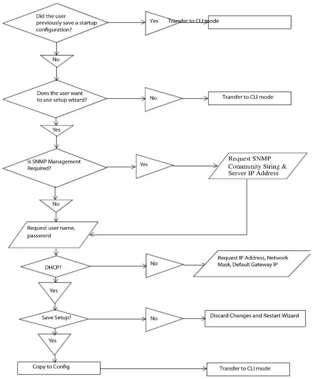
flowchart
graph TD
    A["Did the user previously save a startup configuration?"] --> B{No}
    B --> C{Does the user want to use setup wizard?}
    C -->|Yes| D["Transfer to CLI mode"]
    C -->|No| E["Transfer to CLI mode"]
    D --> F{Is SNMP Management Required?}
    E --> F
    F -->|Yes| G["Request SNMP Community String & Server IP Address"]
    F -->|No| H["Request user name, password"]
    G --> I{DHCP?}
    I -->|No| J["Request IP Address, Network Mask, Default Gateway IP"]
    I -->|Yes| K{Save Setup?}
    K -->|No| L["Discard Changes and Restart Wizard"]
    K -->|Yes| M["Copy to Config"]
    L --> N["Transfer to CLI mode"]
    M --> N
Example Session
This section describes an Easy Setup Wizard session. Refer to the state diagram in the previous section for general flow. The following values used by the example session are not the only possible ones:
- IP address for the VLAN 1 is 192.168.1.2:255.255.255.0. This address is on a different subnet than the OOB interface and in the same subnet as the default gateway.
- The user name is admin, and the password should be 8-64 characters in length (admin123).
- The network management system IP address is 192.168.2.1.
• The default gateway is 0.0.0.0. - The SNMP community string to be used is public.
The setup wizard configures the initial values as defined above. After the user completes the wizard, the system is configured as follows:
- SNMPv1/2c is enabled and the community string is set up as defined above. SNMPv3 is disabled.
- The admin user account is set up as defined.
- The address of the network management station is configured. From this management station, the user can access the SNMP, HTTP, and CLI interfaces. The user may also choose to allow all IP addresses to access switch management by choosing the (0.0.0.0) IP address.
- An IP address is configured for the default VLAN (1).
- A default gateway address is configured.
The following example contains the sequence of prompts and responses associated with running an example Dell Easy Setup Wizard session, using the input values listed above. Note in this case a static IP address for the management interface is being set up. However it may be requested that the system automatically retrieve an IP address via DHCP. If DHCP is used, the system does not request a network mask or default gateway. In this example, the user employs the setup wizard to configure the initial values as defined above.

NOTE: In the following Easy Setup Wizard example, the possible user options are enclosed in []. Also, where possible, default values are enclosed in []. If the user enters
After the switch completes the POST and is booted, the following dialog appears:
Welcome to Dell Easy Setup Wizard
The Setup Wizard guides you through the initial switch configuration, and gets you up and running as quickly as possible. You can skip the setup wizard, and enter CLI mode to manually configure the switch. You must respond to the next question to run the setup wizard within 60 seconds, otherwise the system will continue with normal operation using the default system configuration. Note: You can exit the setup wizard at any point by entering [ctrl+z].
Would you like to run the setup wizard (you must answer this question within 60 seconds)? [Y/N] y
Step 1:
The system is not setup for SNMP management by default. To manage the switch using SNMP (required for Dell Network Manager) you can:
o Set up the initial SNMP version 2 account now.
o Return later and setup other SNMP accounts. (For more information on setting up an SNMP version 1 or 3 account, see the user documentation).
Would you like to setup the SNMP management interface now? [Y/N] y
To setup the SNMP management account you must specify the management system IP address and the "community string" or password that the particular management system uses to access the switch. The wizard automatically assigns the highest access level
[Privilege Level 15] to this account. You can use Dell
Network Manager or other management interfaces to change this setting, and to add additional management system later. For more information on adding management systems, see the user documentation.
To add a management station:
Please enter the SNMP community string to be used.
{public}:
public
Please enter the IP address of the Management System (A.B.C.D) or wildcard (0.0.0.0) to manage from any Management Station.
0.0.0.0 :
192.168.2.1
Step 2:
Now we need to setup your initial privilege (Level 15) user account. This account is used to login to the CLI and Web interface. You may setup other accounts and change privilege levels later. For more information on setting up user accounts and changing privilege levels, see the user documentation.
To setup a user account:
Please enter the user name: admin
Please enter the user password: *****
Please reenter the user password: *****
Step 3:
Next, an IP address is setup. The IP address is defined on the default VLAN (VLAN #1), of which all ports are members. This is the IP address you use to access the CLI, Web interface, or SNMP interface for the switch.
Optionally you may request that the system automatically retrieve an IP address from the network via DHCP (this requires that you have a DHCP server running on the network).
To setup an IP address:
Please enter the IP address of the device (A.B.C.D) or enter "DHCP" (without the quotes) to automatically request an IP address from the network DHCP server.
192.168.1.2
Please enter the IP subnet mask (A.B.C.D or /nn):
255.255.255.0
Step 4:
Finally, set up the gateway. Please enter the IP address of the gateway from which this network is reachable
192.168.1.1
This is the configuration information that has been collected:
SNMP Interface = "public"@192.168.2.1
User Account setup = admin
Password = *****
Management IP address = 192.168.2.1 255.255.255.0
Gateway = 0.0.0.0
Step 5:
If the information is correct, please select (Y) to save the configuration, and copy to the start-up configuration file. If the information is incorrect, select (N) to discard configuration and restart the wizard: [Y/N]
y
Thank you for using the Dell Easy Setup Wizard. You will now enter CLI mode.
...... console>
Using CLI Functions and Tools
The CLI has been designed to manage the switch's configuration file system and to manage switch security. A number of resident tools exist to support these and other functions.
Configuration Management
All managed systems have software images and databases that must be configured, backed up and restored. Two software images may be stored on the system, but only one of them is active. The other one is a backup image. The same is true for configuration images, which store the configuration parameters for the switch. The system has three configuration images. One image is a memory-only image and is the current configuration image for the switch. The second image is the one that is loaded by the system when it reboots. There is one backup configuration image. The system also provides methods to back up these images to a remote system.
File System Commands
All files are stored in a flat file system. The commands shown in Table 2-6 are used to perform operations on these files.
Table 2-6. File System Commands
| Command Description | |
| delete file | Deletes file. |
| filedescr file description | Adds a description to a file (up to 20 characters can be used). |
| copy source destination | Copies a file from source file to destination file. |
Copying Files
The copy command not only provides a method for copying files within the file system, but also to and from remote servers. With the copy command and URLs to identify files, the user can back up images to local or remote systems or restore images from local or remote systems.
To use the copy command, the user specifies the source file and the destination file. For example, copy tftp://remotehost/pub/backupfile backup-config copies a file from the remote TFTP server to a local backup configuration file. In this case, if the local configuration file does not exist, then it is created by the command. If it does exist, it is overwritten. If there is not enough space on the local file system to accommodate the file, an error is flagged.
Refer to the copy command description on page 1501 in the Layer 2 commands section of the guide for command details.
Referencing External/Internal File systems
Configuration or software images are copied to or retrieved from remote file systems using the TFTP protocol.
- tftp://server-name/path/filename — identifies a file on a remote file system accessible through the server-name. Trivial file transfer protocol is a simplified FTP and uses a UDP port instead of TCP and does not have password protection.
Special System Files
The following special filenames are used to refer to special virtual system files, which are under control of the system and may not be removed or added. These file names are reserved and may not be used as user-defined files. When the user copies a local source file into one of these special files and the source file has an attached file description, it also is copied as the file description for the special file.
- backup-config — This file refers to the backup configuration file.
- running-config — This file refers to the configuration file currently active in the system. It is possible to copy the running-config image to a backup-config file or to the startup-config file.
- startup-config — This file refers to the special configuration image stored in flash memory which is loaded when the system next reboots. The user may copy a particular configuration file (remote or local) to this special file name and reboot the system to force it to use a particular configuration.
- image1 & image2 — These files refer to software images. One of these will be loaded when the system next reboots. Either image1 or image2 can be chosen for the next reboot using the command boot system.
The CLI prevents the user from accidentally copying a configuration image onto a software image and vice versa.
Management Interface Security
This section describes the minimum set of management interface security measures implemented by the CLI. Management interface security consists of user account management, user access control and remote network/host access controls.
CLI through Telnet, SSH, Serial Interfaces
The CLI is accessible through a local serial interface, the service port (out-of-band interface), or in-band interfaces. Since the serial interface requires a physical connection for access, it is used if all else fails. The serial interface is the only interface from which the user may access the Easy Setup Wizard. It is the only interface that the user can access if the remote authentication servers are down and the user has not configured the system to revert to local managed accounts.
The following rules and specifications apply to these interfaces:
- The CLI is accessible from remote telnet through the IP address for the switch. IP addresses are assigned separately for the out-of-band interface and the in-band ports.
- The CLI is accessible from a secure shell interface.
- The CLI generates keys for SSH locally.
- The serial session defaults to 9600 baud rate, eight data bits, non-parity and one stop bit.
User Accounts Management
The CLI provides authentication for users either through remote authentication servers supporting TACACS+ or Radius or through a set of locally managed user accounts. The setup wizard asks the user to create the initial administrator account and password at the time the system is booted.
The following rules and specifications apply:
- The user may create five local user accounts.
- User accounts have an access level, a user name, and a user password.
- The user is able to delete the user accounts but the user will not be able to delete the last level 15 account.
- The user password is saved internally in encrypted format and never appears in clear text anywhere on the CLI.
- The CLI supports TACACS+ and Radius authentication servers.
- The CLI allows the user to configure primary and secondary authentication servers. If the primary authentication server fails to respond within a configurable period, the CLI automatically tries the secondary authentication server.
- The user can specify whether the CLI should revert to using local user accounts when the remote authentication servers do not respond or if the CLI simply fails the login attempt because the authentication servers are down. This requirement applies only when the user is logged in through a telnet or an SSH session.
- The CLI always allows the user to log in to a local serial port even if the remote authentication server(s) are down. In this case, CLI reverts to using the locally configured accounts to allow the user to log in.
User Access Control
In addition to authenticating a user, the CLI also assigns the user access to one of two security levels. Level 1 has read-only access. This level allows the user to read information but not configure the switch. The access to this level cannot be modified. Level 15 is the special access level assigned to the superuser of the switch. This level has full access to all functions within the switch and can not be modified.
If the user account is created and maintained locally, each user is given an access level at the time of account creation. If the user is authenticated through remote authentication servers, the authentication server is configured to pass the user access level to the CLI when the user is authenticated. When Radius is used, the Vendor-Specific Optionfield returns the access level for the user. Two vendor specific options are supported. These are CISCO-AV-Pairs(Shell:priv-lvl=x) and Dell Radius VSA (user-group=x). TACACS+ provides the appropriate level of access.
The following rules and specifications apply:
- The user determines whether remote authentication servers or locally defined user authentication accounts are used.
- If authentication servers are used, the user can identify at least two remote servers (the user may choose to configure only one server) and what protocol to use with the server, TACACS+ or Radius. One of the servers is primary and the other is the secondary server (the user is not required to specify a secondary server). If the primary server fails to respond in a configurable time period, the CLI automatically attempts to authenticate the user with the secondary server.
- The user is able to specify what happens when both primary and secondary servers fail to respond. In this case, the user is able to indicate that the CLI should either use the local user accounts or reject all requests.
- Even if the user configures the CLI to fail login when the remote authentication servers are down, the CLI allows the user to log in to the serial interface authenticated by locally managed account data.
Syslogs
The CLI uses syslog support to send logging messages to a remote syslog server. The user configures the switch to generate all logging messages to a remote log server. If no remote log server exists, then the CLI maintains a rolling log of at most the last 1000 critical system events.
The following rules and specifications apply:
- The CLI permits the user to configure a remote syslog server to which all system logging messages are sent.
- Log messages are implementation-dependent but may contain debug messages, security or fault events.
- If a log server is not specified by the user, the CLI maintains at most the last 1000 critical system events. In this case, less important events are not recorded.
Security Logs
Security logs are maintained to record all security events including the following:
- User login.
• U s e r l o g o u t .
- Den i ed l o g i n a t t e m p t s .
- User attempt to exceed security access level.
- Denied attempts by external management system to access the system.
The security log record contains the following information:
- The user name, if available, or the protocol being accessed if the event is related to a remote management system.
- The IP address from which the user is connecting or the IP address of the remote management system.
• A description of the security event.
• A timestamp of the event
If syslog is available, the CLI sends the security log records to the syslog server. If syslog is not available, the CLI records the last 1000 security log records in a log separate from the system log records itemized above. Also in this case, the CLI suppresses repeated events from the same source and instead the CLI records one event within a period of time and includes that count as part of the log.
Management ACL
In addition to user access control, the system also manages access for in-band interfaces. The system allows individual hosts or subnets to access only specific management protocols.
The user defines a management profile, which identifies management protocols such as the following:
- T e l n e t .
- SSH and the keying information to use for SSH.
- HTTP.
- HTTPS and the security certificate to be used.
- SNMPv1/v2c and the read and read/write community strings to be used.
- SNMPv3 and the security information for used this protocol.
For each of these management profiles, the user defines the list of hosts or subnets from which the management profiles may be used.
Other CLI Tools and Capabilities
The CLI has several other capabilities associated with its primary functions.
Terminal Paging
The terminal width and length for CLI displays is 79 characters and 25 lines, respectively. The length setting is used to control the number of lines the CLI will display before it pauses. For example, the CLI pauses at 24 lines and prompts the user with the -more- prompt on the 25th line. The CLI waits for the user to press either or any other key. If the user presses any key except
, the CLI shows the next page. A
key stops the display and returns to the CLI prompt.
Boot Message
The boot message is a system message that is not user-configurable and is displayed when the system is booting. Displayed information includes the following:
- Operational code date
- The board type
• T h e C P U
- Memory size
To start the normal booting process, select item 1 in the Boot Menu. The following is a sample log for booting information.
Boot Menu 4.1.0.6
CPU Card ID: 0x508548
CFI Probe: Found 2x16 devices in x16 mode
/DskVol// - disk check in progress ...
/DskVol// - Volume is OK
volume descriptor ptr (pVolDesc): 0x814cf10
XBD device block I/O handle: 0x10001
auto disk check on mount: DOS_CHK_REPAIR | DOS_CHK_VERB_2
volume write mode: copyback (DOS_WRITE)
volume options:
max # of simultaneously open files: 52
file descriptors in use: 0
# of different files in use: 0
# of descriptors for deleted files: 0
# of obsolete descriptors: 0
current volume configuration:
- volume label: NO LABEL ; (in boot sector: )
- volume Id: 0xbb
- total number of sectors: 124,408
- bytes per sector: 512
- # of sectors per cluster: 4
- # of reserved sectors: 1
- FAT entry size: FAT16
- # of sectors per FAT copy: 122
-
of FAT table copies: 2
-
of hidden sectors: 8
- first cluster is in sector # 260
- Update last access date for open-read-close = FALSE
Boot Menu 4.1.0.6
Select an option. If no selection in 10 seconds then operational code will start.
1 - Start operational code.
2 - Start Boot Menu.
Select (1, 2):
Operational Code Date: Mon Feb 28 16:43:14 2011
Uncompressing.....
Bulk Class Driver Successfully Initialized
Adding 0 symbols for standalone.
CFI Probe: Found 2x16 devices in x16 mode
volume descriptor ptr (pVolDesc): 0x5157150
XBD device block I/O handle: 0x10001
auto disk check on mount: DOS_CHK_REPAIR | DOS_CHK_VERB_2
volume write mode: copyback (DOS_WRITE)
volume options:
max # of simultaneously open files: 52
file descriptors in use: 0
# of different files in use: 0
# of descriptors for deleted files: 0
# of obsolete descriptors: 0
current volume configuration:
- volume label: NO LABEL ; (in boot sector: )
- volume Id: 0xbb
- total number of sectors: 124,408
- bytes per sector: 512
-
of sectors per cluster: 4
-
of reserved sectors: 1
- FAT entry size: FAT16
-
of sectors per FAT copy: 122
-
of FAT table copies: 2
-
of hidden sectors: 8
- first cluster is in sector # 260
- Update last access date for open-read-close = FALSE
PCI unit 0: Dev 0xb634, Rev 0x11, Chip BCM56634_B0, Driver BCM56634_B0
SOC unit 0 attached to PCI device BCM56634_B0
soc_reset_bcm56634_a0: TCAM PLL not locked.
Adding BCM transport pointers
Configuring CPUTRANS TX
Configuring CPUTRANS RX
hpc - No stack ports. Starting in stand-alone mode.
Instantiating /download as rawFs, device = 0x20001
Formatting /download for DOSFS
Instantiating /download as rawFs, device = 0x20001
Formatting...OK.
<186> NOV 15 09:34:53 0.0.0.0-1 General[1073741072]:bootos.c(220) 1
%% Event(0xaaaaaaa)Instantiating RamCP: as rawFs, device = 0x30001
Formatting RamCP: for DOSFS
Instantiating RamCP: as rawFs, device = 0x30001
Formatting...OK.
(Unit 1 - Waiting to select management unit) > Applying Global configuration, please wait ... Applying Interface configuration, please wait ... console >
Boot Utility Menu
If a user is connected through the serial interface during the boot sequence, pressing the
Boot Menu 4.1.0.6
Options available
1 - Start operational code
2 - Change baud rate
3 - Retrieve event log using XMODEM
4 - Load new operational code using XMODEM
5 - Display operational code vital product data
6 - Abort boot code update
7 - Update boot code
8 - Delete backup image
9 - Reset the system
10 - Restore configuration to factory defaults (delete config files)
11 - Activate Backup Image
12 - Password Recovery Procedure
13 - Reformat and restore file system
[Boot Menu] 2
Select baud rate:
1 - 1200
2 - 2400
3 - 4800
4 - 9600
5 - 19200
6 - 38400
7 - 57600
8 - 115200
0 - no change
Baud rate is not changed
[Boot Menu] 3
Sending event log, start XMODEM receive.....
File asciilog.bin Ready to SEND in binary mode
Estimated File Size OK, 12 Sectors, 89 Bytes
Estimated transmission time 14 seconds
Send several Control-X characters to cancel before transfer starts.
[Boot Menu] 4
Ready to receive the file with XMODEM/CRC....
Ready to RECEIVE File xcode.bin in binary mode
Send several Control-X characters to cancel before transfer starts.
СКСК
[Boot Menu] 5
The following image is in the Flash File System:
File Name......image2
CRC....0x3431
(13361)
Target
Device....0x00508548
Size....0xc178 dc (12679388)
Number of Components....3
Operational Code Size....0xa73af4 (10959604)
Operational Code Offset....0x74 (116)
Operational Code FLASH flag....1
Operational Code CRC....0x20E7
Operational Compression flag....2 (1zma)
Boot Code Version....1
Boot Code
Size....0x100000 (1048576)
Boot Code
Offset....0xa73b68 (10959720)
Boot Code FLASH flag....0
Boot Code CRC....0x578
VPD - rel 4 ver 1 maint_lvl 0 build_num 6
Timestamp - Mon Feb 28 16:43:14 2011
File - PC7000_M6348v4.1.0.6.opr
[Boot Menu] 6
[Boot Menu] 7
Do you wish to update Boot Code and reset? (y/n) y
Validating image2....OK
Extracting boot code from image...CRC valid
Erasing Boot Flash.....Done.
Wrote 0x10000 bytes.
Wrote 0x20000 bytes.
Wrote 0x30000 bytes.
Wrote 0x40000 bytes.
Wrote 0x50000 bytes.
Wrote 0x60000 bytes.
Wrote 0x70000 bytes.
Wrote 0x80000 bytes.
Wrote 0x90000 bytes.
Wrote 0xa0000 bytes.
Wrote 0xb0000 bytes.
Wrote 0xc0000 bytes.
Wrote 0xd0000 bytes.
Wrote 0xe0000 bytes.
Wrote 0xf0000 bytes.
Wrote 0x100000 bytes.
Validating Flash.....Passed
Flash update completed.
Rebooting...
CPU Card ID: 0x508548
CFI Probe: Found 2x16 devices in x16 mode
/DskVol// - disk check in progress ...
/DskVol// - Volume is OK
Change volume Id from 0x0 to 0x79
volume descriptor ptr (pVolDesc): 0x814cf10
XBD device block I/O handle: 0x10001
auto disk check on mount: DOS_CHK_REPAIR | DOS_CHK_VERB_2
volume write mode: copyback (DOS_WRITE)
volume options:
max # of simultaneously open files: 52
file descriptors in use: 0
# of different files in use: 0
# of descriptors for deleted files: 0
# of obsolete descriptors: 0
current volume configuration:
- volume label: NO LABEL ; (in boot sector: )
- volume Id: 0x79
- total number of sectors: 124,408
- bytes per sector: 512
- # of sectors per cluster: 4
- # of reserved sectors: 1
- FAT entry size: FAT16
- # of sectors per FAT copy: 122
- # of FAT table copies: 2
- # of hidden sectors: 8
- first cluster is in sector # 260
- Update last access date for open-read-close = FALSE
Boot Menu 4.1.0.6
Select an option. If no selection in 10 seconds then operational code will start.
1 - Start operational code.
2 - Start Boot Menu.
Select (1, 2):2
Boot Menu 4.1.0.6
Options available
1 - Start operational code
2 - Change baud rate
3 - Retrieve event log using XMODEM
4 - Load new operational code using XMODEM
5 - Display operational code vital product data
6 - Abort boot code update
7 - Update boot code
8 - Delete backup image
9 - Reset the system
10 - Restore configuration to factory defaults (delete config files)
11 - Activate Backup Image
12 - Password Recovery Procedure
13 - Reformat and restore file system
[Boot Menu] 8
Are you SURE you want to delete: image1 ? (y/n):y image1 deleted...
[Boot Menu] 10
Are you SURE you want to delete the configuration? (y/n):y
[Boot Menu] 11
Backup image - image1 activated.
[Boot Menu] 12
Operational Code Date: Mon Feb 28 16:43:14 2011
Uncompressing.....
Bulk Class Driver Successfully Initialized
Adding 0 symbols for standalone.
CFI Probe: Found 2x16 devices in x16 mode
volume descriptor ptr (pVolDesc): 0x5157150
XBD device block I/O handle: 0x10001
auto disk check on mount: DOS_CHK_REPAIR | DOS_CHK_VERB_2
volume write mode: copyback (DOS_WRITE)
volume options:
max # of simultaneously open files: 52
file descriptors in use: 0
# of different files in use: 0
# of descriptors for deleted files: 0
# of obsolete descriptors: 0
current volume configuration:
- volume label: NO LABEL ; (in boot sector: )
- volume Id: 0x79
- total number of sectors: 124,408
- bytes per sector: 512
- # of sectors per cluster: 4
- # of reserved sectors: 1
- FAT entry size: FAT16
- # of sectors per FAT copy: 122
- # of FAT table copies: 2
- # of hidden sectors: 8
- first cluster is in sector # 260
- Update last access date for open-read-close = FALSE
PCI unit 0: Dev 0xb634, Rev 0x11, Chip BCM56634_B0, Driver BCM56634_B0
SOC unit 0 attached to PCI device BCM56634_B0
soc_reset_bcm56634_a0: TCAM PLL not locked.
Adding BCM transport pointers
Configuring CPUTRANS TX
Configuring CPUTRANS RX
Instantiating /download as rawFs, device = 0x20001
Formatting /download for DOSFS
Instantiating /download as rawFs, device = 0x20001
Formatting...OK.
<186> NOV 15 10:03:48 0.0.0.0-1 General [1073741072]: bootos.c(220) 1 % Event (0xaaaaaaaaa)
Instantiating RamCP: as rawFs, device = 0x30001 Formatting RamCP: for DOSFS Instantiating RamCP: as rawFs, device = 0x30001 Formatting...OK.
(Unit 1 - Waiting to select management unit) > USB Auto Configuration process is completed!
Applying Global configuration, please wait ...
Welcome to Dell Easy Setup Wizard
The setup wizard guides you through the initial switch configuration, and gets you up and running as quickly as possible. You can skip the setup wizard, and enter CLI mode to manually configure the switch. You must respond to the next question to run the setup wizard within 60 seconds, otherwise the system will continue with normal operation using the default system configuration. Note: You can exit the setup wizard at any point by entering [ctrl+z].
Would you like to run the setup wizard (you must answer this question within 60 seconds)? [Y/N] n
Thank you for using the Dell Easy Setup Wizard. You will now enter CLI mode.
Applying Interface configuration, please wait ...
console>en
console#reload
Management switch has unsaved changes.
Are you sure you want to continue? (y/n) y
Configuration Not Saved!
Are you sure you want to reload the stack? (y/n) y
Reloading all switches.
Boot Menu 4.1.0.6
CPU Card ID: 0x508548
CFI Probe: Found 2x16 devices in x16 mode
/DskVol// - disk check in progress ...
/DskVol//files
/DskVol//files/image2
/DskVol//files/boot.dim
/DskVol//files/crashdump.ctl
/DskVol//files/dh512.pem
/DskVol//files/dh1024.pem
/DskVol//files/sslt_cert1.pem
/DskVol//files/sslt_key1.pem
/DskVol//files/ssh_host_key
/DskVol//files/ssh_host_dsa_key
/DskVol//files/ssh_host_rsa_key
/DskVol//files/log2.bin
/DskVol//files/hpc_broad.cfg
/DskVol//files/slog0.txt
/DskVol//files/olog0.txt
/DskVol//files/sslt.rnd
/DskVol// - Volume is OK
volume descriptor ptr (pVolDesc): 0x814cf10
XBD device block I/O handle: 0x10001
auto disk check on mount: DOS_CHK_REPAIR | DOS_CHK_VERB_2
volume write mode: copyback (DOS_WRITE)
volume options:
max # of simultaneously open files: 52
file descriptors in use: 0
<h1 id="of-different-files-in-use-0">of different files in use: 0</h1>
<h1 id="of-descriptors-for-deleted-files-0">of descriptors for deleted files: 0</h1>
<h1 id="of-obsolete-descriptors-0">of obsolete descriptors: 0</h1>
current volume configuration:
- volume label: NO LABEL ; (in boot sector: )
- volume Id: 0x79
- total number of sectors: 124,408
- bytes per sector: 512
- # of sectors per cluster: 4
- # of reserved sectors: 1
- FAT entry size: FAT16
- # of sectors per FAT copy: 122
- # of FAT table copies: 2
- # of hidden sectors: 8
- first cluster is in sector # 260
- Update last access date for open-read-close = FALSE
Boot Menu 4.1.0.6
Select an option. If no selection in 10 seconds then operational code will start.
1 - Start operational code.
2 - Start Boot Menu.
Select (1, 2):2
Boot Menu 4.1.0.6
Options available
1 - Start operational code
2 - Change baud rate
3 - Retrieve event log using XMODEM
4 - Load new operational code using XMODEM
5 - Display operational code vital product data
6 - Abort boot code update
7 - Update boot code
8 - Delete backup image
9 - Reset the system
10 - Restore configuration to factory defaults (delete config files)
11 - Activate Backup Image
12 - Password Recovery Procedure
13 - Reformat and restore file system
[Boot Menu] 13
Instantiating /RamDisk/ as rawFs, device = 0x20001
Formatting /RamDisk/ for DOSFS
Instantiating /RamDisk/ as rawFs, device = 0x20001
Formatting.../RamDisk/: file system is marked clean, skipping check
OK.
copying file /DskVol/files/image1 -> /RamDisk/image1
copying file /DskVol/files/image2 -> /RamDisk/image2
copying file /DskVol/files/startup-config ->
/RamDisk/startup-config
copying file /DskVol/files/vpd.bin ->
/RamDisk/vpd.bin
copying file /DskVol/files/hpc_broad.cfg ->
/RamDisk/hpc_broad.cfg
copying file /DskVol/files/boot.dim ->
/RamDisk/boot.dim
copying file /DskVol/files/dh512.pem ->
/RamDisk/dh512.pem
copying file /DskVol/files/dh1024.pem ->
/RamDisk/dh1024.pem
copying file /DskVol/files/ssl_t_cert1.pem ->
/RamDisk/ssl_t_cert1.pem
copying file /DskVol/files/ssl_t_key1.pem ->
/RamDisk/ssl_t_key1.pem
copying file /DskVol/files/ssh_host_key -> /RamDisk/ssh_host_key
copying file /DskVol/files/ssh_host_dsa_key -> /RamDisk/ssh_host_dsa_key
copying file /DskVol/files/ssh_host_rsa_key -> /RamDisk/ssh_host_rsa_key
image2 12679504 11/15/113 9:30:36
hpc_broad.cfg 148 11/15/113 10:04:30
boot.dim 77 4/22/105 8:00:02
dh512.pem 156 5/30/113 0:20:24
dh1024.pem 245 5/30/113 0:20:24
sslt_cert1.pem 863 6/2/113 5:09:30
sslt_key1.pem 887 6/2/113 5:09:30
ssh_host_key 517 5/30/113 0:20:24
ssh_host_dsa_key 672 5/30/113 0:20:24
ssh_host_rsa_key 887 5/30/113 0:20:24
Filesystem size 25484288
Bytes used 12683956
Bytes free 12800332
Erasing FFS: CFI Probe: Found 2x16 devices in x16 mode
Formatted 1 of 251 units = 0.3 %
Formatted 2 of 251 units = 0.7 %
Formatted 3 of 251 units = 1.1 %
Formatted 4 of 251 units = 1.5 %
Formatted 5 of 251 units = 1.9 %
Formatted 6 of 251 units = 2.3 %
Formatted 7 of 251 units = 2.7 %
Formatted 8 of 251 units = 3.1 %
Formatted 9 of 251 units = 3.5 %
Formatted 10 of 251 units = 3.9 %
Formatted 11 of 251 units = 4.3 %
Formatted 12 of 251 units = 4.7 %
Formatted 13 of 251 units = 5.1 %
Formatted 14 of 251 units = 5.5 %
Formatted 15 of 251 units = 5.9 %
Formatted 16 of 251 units = 6.3 %
Formatted 17 of 251 units = 6.7 %
Formatted 18 of 251 units = 7.1 %
Formatted 19 of 251 units = 7.5 %
Formatted 20 of 251 units = 7.9 %
Formatted 21 of 251 units = 8.3 %
Formatted 22 of 251 units = 8.7 %
Formatted 23 of 251 units = 9.1 %
Formatted 24 of 251 units = 9.5 %
Formatted 25 of 251 units = 9.9 %
| Formatted 26 of 251 units = 10.3 % |
| Formatted 27 of 251 units = 10.7 % |
| Formatted 28 of 251 units = 11.1 % |
| Formatted 29 of 251 units = 11.5 % |
| Formatted 30 of 251 units = 11.9 % |
| Formatted 31 of 251 units = 12.3 % |
| Formatted 32 of 251 units = 12.7 % |
| Formatted 33 of 251 units = 13.1 % |
| Formatted 34 of 251 units = 13.5 % |
| Formatted 35 of 251 units = 13.9 % |
| Formatted 36 of 251 units = 14.3 % |
| Formatted 37 of 251 units = 14.7 % |
| Formatted 38 of 251 units = 15.1 % |
| Formatted 39 of 251 units = 15.5 % |
| Formatted 40 of 251 units = 15.9 % |
| Formatted 41 of 251 units = 16.3 % |
| Formatted 42 of 251 units = 16.7 % |
| Formatted 43 of 251 units = 17.1 % |
| Formatted 44 of 251 units = 17.5 % |
| Formatted 45 of 251 units = 17.9 % |
| Formatted 46 of 251 units = 18.3 % |
| Formatted 47 of 251 units = 18.7 % |
| Formatted 48 of 251 units = 19.1 % |
| Formatted 49 of 251 units = 19.5 % |
| Formatted 50 of 251 units = 19.9 % |
| Formatted 51 of 251 units = 20.3 % |
| Formatted 52 of 251 units = 20.7 % |
| Formatted 53 of 251 units = 21.1 % |
| Formatted 54 of 251 units = 21.5 % |
| Formatted 55 of 251 units = 21.9 % |
| Formatted 56 of 251 units = 22.3 % |
| Formatted 57 of 251 units = 22.7 % |
| Formatted 58 of 251 units = 23.1 % |
| Formatted 59 of 251 units = 23.5 % |
| Formatted 60 of 251 units = 23.9 % |
| Formatted 61 of 251 units = 24.3 % |
| Formatted 62 of 251 units = 24.7 % |
| Formatted 63 of 251 units = 25.0 % |
| Formatted 64 of 251 units = 25.4 % |
| Formatted 65 of 251 units = 25.8 % |
| Formatted 66 of 251 units = 26.2 % |
| Formatted 67 of 251 units = 26.6 % |
| Formatted 68 of 251 units = 27.0 % |
| Formatted 69 of 251 units = 27.4 % |
| Formatted 70 of 251 units = 27.8 % |
| Formatted 71 of 251 units = 28.2 % |
| Formatted 72 of 251 units = 28.6 % |
| Formatted 73 of 251 units = 29.0 % |
| Formatted 74 of 251 units = 29.4 % |
| Formatted 75 of 251 units = 29.8 % |
| Formatted 76 of 251 units = 30.2 % |
| Formatted 77 of 251 units = 30.6 % |
| Formatted 78 of 251 units = 31.0 % |
| Formatted 79 of 251 units = 31.4 % |
| Formatted 80 of 251 units = 31.8 % |
| Formatted 81 of 251 units = 32.2 % |
| Formatted 82 of 251 units = 32.6 % |
| Formatted 83 of 251 units = 33.0 % |
| Formatted 84 of 251 units = 33.4 % |
| Formatted 85 of 251 units = 33.8 % |
| Formatted 86 of 251 units = 34.2 % |
| Formatted 87 of 251 units = 34.6 % |
| Formatted 88 of 251 units = 35.0 % |
| Formatted 89 of 251 units = 35.4 % |
| Formatted 90 of 251 units = 35.8 % |
| Formatted 91 of 251 units = 36.2 % |
| Formatted 92 of 251 units = 36.6 % |
| Formatted 93 of 251 units = 37.0 % |
| Formatted 94 of 251 units = 37.4 % |
| Formatted 95 of 251 units = 37.8 % |
| Formatted 96 of 251 units = 38.2 % |
| Formatted 97 of 251 units = 38.6 % |
| Formatted 98 of 251 units = 39.0 % |
| Formatted 99 of 251 units = 39.4 % |
| Formatted 100 of 251 units = 39.8 % |
| Formatted 101 of 251 units = 40.2 % |
| Formatted 102 of 251 units = 40.6 % |
| Formatted 103 of 251 units = 41.0 % |
| Formatted 104 of 251 units = 41.4 % |
| Formatted 105 of 251 units = 41.8 % |
| Formatted 106 of 251 units = 42.2 % |
| Formatted 107 of 251 units = 42.6 % |
| Formatted 108 of 251 units = 43.0 % |
| Formatted 109 of 251 units = 43.4 % |
| Formatted 110 of 251 units = 43.8 % |
| Formatted 111 of 251 units = 44.2 % |
| Formatted 112 of 251 units = 44.6 % |
| Formatted 113 of 251 units = 45.0 % |
| Formatted 114 of 251 units = 45.4 % |
| Formatted 115 of 251 units = 45.8 % |
| Formatted 116 of 251 units = 46.2 % |
| Formatted 117 of 251 units = 46.6 % |
| Formatted 118 of 251 units = 47.0 % |
| Formatted 119 of 251 units = 47.4 % |
| Formatted 120 of 251 units = 47.8 % |
| Formatted 121 of 251 units = 48.2 % |
| Formatted 122 of 251 units = 48.6 % |
| Formatted 123 of 251 units = 49.0 % |
| Formatted 124 of 251 units = 49.4 % |
| Formatted 125 of 251 units = 49.8 % |
| Formatted 126 of 251 units = 50.1 % |
| Formatted 127 of 251 units = 50.5 % |
| Formatted 128 of 251 units = 50.9 % |
| Formatted 129 of 251 units = 51.3 % |
| Formatted 130 of 251 units = 51.7 % |
| Formatted 131 of 251 units = 52.1 % |
| Formatted 132 of 251 units = 52.5 % |
| Formatted 133 of 251 units = 52.9 % |
| Formatted 134 of 251 units = 53.3 % |
| Formatted 135 of 251 units = 53.7 % |
| Formatted 136 of 251 units = 54.1 % |
| Formatted 137 of 251 units = 54.5 % |
| Formatted 138 of 251 units = 54.9 % |
| Formatted 139 of 251 units = 55.3 % |
| Formatted 140 of 251 units = 55.7 % |
| Formatted 141 of 251 units = 56.1 % |
| Formatted 142 of 251 units = 56.5 % |
| Formatted 143 of 251 units = 56.9 % |
| Formatted 144 of 251 units = 57.3 % |
| Formatted 145 of 251 units = 57.7 % |
| Formatted 146 of 251 units = 58.1 % |
| Formatted 147 of 251 units = 58.5 % |
| Formatted 148 of 251 units = 58.9 % |
| Formatted 149 of 251 units = 59.3 % |
| Formatted 150 of 251 units = 59.7 % |
| Formatted 151 of 251 units = 60.1 % |
| Formatted 152 of 251 units = 60.5 % |
| Formatted 153 of 251 units = 60.9 % |
| Formatted 154 of 251 units = 61.3 % |
| Formatted 155 of 251 units = 61.7 % |
| Formatted 156 of 251 units = 62.1 % |
| Formatted 157 of 251 units = 62.5 % |
| Formatted 158 of 251 units = 62.9 % |
| Formatted 159 of 251 units = 63.3 % |
| Formatted 160 of 251 units = 63.7 % |
| Formatted 161 of 251 units = 64.1 % |
| Formatted 162 of 251 units = 64.5 % |
| Formatted 163 of 251 units = 64.9 % |
| Formatted 164 of 251 units = 65.3 % |
| Formatted 165 of 251 units = 65.7 % |
| Formatted 166 of 251 units = 66.1 % |
| Formatted 167 of 251 units = 66.5 % |
| Formatted 168 of 251 units = 66.9 % |
| Formatted 169 of 251 units = 67.3 % |
| Formatted 170 of 251 units = 67.7 % |
| Formatted 171 of 251 units = 68.1 % |
| Formatted 172 of 251 units = 68.5 % |
| Formatted 173 of 251 units = 68.9 % |
| Formatted 174 of 251 units = 69.3 % |
| Formatted 175 of 251 units = 69.7 % |
| Formatted 176 of 251 units = 70.1 % |
| Formatted 177 of 251 units = 70.5 % |
| Formatted 178 of 251 units = 70.9 % |
| Formatted 179 of 251 units = 71.3 % |
| Formatted 180 of 251 units = 71.7 % |
| Formatted 181 of 251 units = 72.1 % |
| Formatted 182 of 251 units = 72.5 % |
| Formatted 183 of 251 units = 72.9 % |
| Formatted 184 of 251 units = 73.3 % |
| Formatted 185 of 251 units = 73.7 % |
| Formatted 186 of 251 units = 74.1 % |
| Formatted 187 of 251 units = 74.5 % |
| Formatted 188 of 251 units = 74.9 % |
| Formatted 189 of 251 units = 75.2 % |
| Formatted 190 of 251 units = 75.6 % |
| Formatted 191 of 251 units = 76.0 % |
| Formatted 192 of 251 units = 76.4 % |
| Formatted 193 of 251 units = 76.8 % |
| Formatted 194 of 251 units = 77.2 % |
| Formatted 195 of 251 units = 77.6 % |
| Formatted 196 of 251 units = 78.0 % |
| Formatted 197 of 251 units = 78.4 % |
| Formatted 198 of 251 units = 78.8 % |
| Formatted 199 of 251 units = 79.2 % |
| Formatted 200 of 251 units = 79.6 % |
| Formatted 201 of 251 units = 80.0 % |
| Formatted 202 of 251 units = 80.4 % |
| Formatted 203 of 251 units = 80.8 % |
| Formatted 204 of 251 units = 81.2 % |
| Formatted 205 of 251 units = 81.6 % |
| Formatted 206 of 251 units = 82.0 % |
| Formatted 207 of 251 units = 82.4 % |
| Formatted 208 of 251 units = 82.8 % |
| Formatted 209 of 251 units = 83.2 % |
| Formatted 210 of 251 units = 83.6 % |
| Formatted 211 of 251 units = 84.0 % |
| Formatted 212 of 251 units = 84.4 % |
| Formatted 213 of 251 units = 84.8 % |
| Formatted 214 of 251 units = 85.2 % |
| Formatted 215 of 251 units = 85.6 % |
| Formatted 216 of 251 units = 86.0 % |
| Formatted 217 of 251 units = 86.4 % |
| Formatted 218 of 251 units = 86.8 % |
| Formatted 219 of 251 units = 87.2 % |
| Formatted 220 of 251 units = 87.6 % |
| Formatted 221 of 251 units = 88.0 % |
| Formatted 222 of 251 units = 88.4 % |
| Formatted 223 of 251 units = 88.8 % |
| Formatted 224 of 251 units = 89.2 % |
| Formatted 225 of 251 units = 89.6 % |
| Formatted 226 of 251 units = 90.0 % |
| Formatted 227 of 251 units = 90.4 % |
| Formatted 228 of 251 units = 90.8 % |
| Formatted 229 of 251 units = 91.2 % |
| Formatted 230 of 251 units = 91.6 % |
| Formatted 231 of 251 units = 92.0 % |
| Formatted 232 of 251 units = 92.4 % |
| Formatted 233 of 251 units = 92.8 % |
Formatted 234 of 251 units = 93.2 %
Formatted 235 of 251 units = 93.6 %
Formatted 236 of 251 units = 94.0 %
Formatted 237 of 251 units = 94.4 %
Formatted 238 of 251 units = 94.8 %
Formatted 239 of 251 units = 95.2 %
Formatted 240 of 251 units = 95.6 %
Formatted 241 of 251 units = 96.0 %
Formatted 242 of 251 units = 96.4 %
Formatted 243 of 251 units = 96.8 %
Formatted 244 of 251 units = 97.2 %
Formatted 245 of 251 units = 97.6 %
Formatted 246 of 251 units = 98.0 %
Formatted 247 of 251 units = 98.4 %
Formatted 248 of 251 units = 98.8 %
Formatted 249 of 251 units = 99.2 %
Formatted 250 of 251 units = 99.6 %
Formatted 251 of 251 units = 100.0 %
CFI Probe: Found 2x16 devices in x16 mode
Recreating FFS: CFI Probe: Found 2x16 devices in x16 mode
/DskVol/: file system is marked clean, skipping check
volume descriptor ptr (pVolDesc): 0x9a67710
XBD device block I/O handle: 0x40001
auto disk check on mount: DOS_CHK_REPAIR | DOS_CHK_VERB_2
volume write mode: copyback (DOS_WRITE)
volume options:
max # of simultaneously open files: 52
file descriptors in use: 0
# of different files in use: 0
# of descriptors for deleted files: 0
# of obsolete descriptors: 0
current volume configuration:
- volume label: NO LABEL ; (in boot sector: )
- volume Id: 0x0
- total number of sectors: 124,408
- bytes per sector: 512
- # of sectors per cluster: 4
- # of reserved sectors: 1
- FAT entry size: FAT16
- # of sectors per FAT copy: 122
- # of FAT table copies: 2
- # of hidden sectors: 8
- first cluster is in sector # 260
- Update last access date for open-read-close = FALSE
done
•
. .
Filesystem size 63567872
Bytes used 0
Bytes free 63567872
copying file /RamDisk/image1 -> /DskVol/files/image1
copying file /RamDisk/image2 -> /DskVol/files/image2
copying file /RamDisk/startup-config -> /DskVol/files/startup-config
copying file /RamDisk/vpd.bin -> /DskVol/files/vpd.bin
copying file /RamDisk/hpc_broad.cfg -> /DskVol/files/hpc_broad.cfg
copying file /RamDisk/boot.dim -> /DskVol/files/boot.dim
copying file /RamDisk/dh512.pem -> /DskVol/files/dh512.pem
copying file /RamDisk/dh1024.pem -> /DskVol/files/dh1024.pem
copying file /RamDisk/sslt_cert1.pem -> /DskVol/files/sslt_cert1.pem
copying file /RamDisk/sslt_key1.pem -> /DskVol/files/sslt_key1.pem
copying file /RamDisk/ssh_host_key -> /DskVol/files/ssh_host_key
copying file /RamDisk/ssh_host_dsa_key -> /DskVol/files/ssh_host_dsa_key
copying file /RamDisk/ssh_host_rsa_key -> /DskVol/files/ssh_host_rsa_key
•
. .
image2 12679504 11/15/113
9:30:36
hpc_broad.cfg 148 11/15/113
10:04:30
boot.dim 77 4/22/105
8:00:02
dh512.pem 156 5/30/113
0:20:24
dh1024.pem 245 5/30/113
0:20:24
sslt_cert1.pem 863 6/2/113
5:09:30
sslt_key1.pem 887 6/2/113
5:09:30
ssh_host_key 517 5/30/113
0:20:24
ssh_host_dsa_key 672 5/30/113
0:20:24
ssh_host_rsa_key 887 5/30/113
0:20:24
Filesystem size 63567872
Bytes used 12683956
Bytes free 50883916
[Boot Menu]
Monitoring Traps from CLI
It is possible to connect to the CLI session and monitor the events or faults that are being sent as traps from the system. This feature is equivalent to the alarm-monitoring window in a typical network management system. The user enables events or monitor traps from the CLI by entering the command logging console. Traps generated by the system are dumped to all CLI sessions that have requested monitoring mode to be enabled. The no logging console command disables trap monitoring for the session. By default, console logging is enabled.
Layer 2 Switching Commands
The chapters that follow describe commands that conform to the OSI model data link layer (Layer 2). Layer 2 commands provide a logical organization for transmitting data bits on a particular medium. This layer defines the framing, addressing, and checksum functions for Ethernet packets.
This section of the document contains the following Layer 2 topics:
| AAA Commands E-mail Alerting Commands | IPv6 MLD Snooping Commands | Port Monitor Commands | |
| ACL Commands Ethernet Configuration Commands | IPv6 MLD Snooping Querier Commands | QoS Commands | |
| Address Table Commands | Ethernet CFM Commands | IP Source Guard Commands | RADIUS Commands |
| Auto-VoIP Commands | - | iSCSI Optimization Commands | Spanning Tree Commands |
| CDP Interoperability Commands | GVRP Commands | Link Dependency Commands | TACACS+ Commands |
| DHCP Layer 2 Relay Commands | IGMP Snooping Commands | LLDP Commands | VLAN Commands |
| DHCP Management Interface Commands | IGMP Snooping Querier Commands | Multicast VLAN Registration Commands | Voice VLAN Commands |
| DHCP Snooping Commands | IP Addressing Commands | Port Aggregator Commands | 802.1x Commands |
| Dynamic ARP Inspection Commands | IPv6 Access List Commands | Port Channel Commands | - |
AAA Commands
Management access to the switch is via telnet, HTTP, SSH, or the serial console (SNMP access is discussed in SNMP Commands). To ensure that only authorized users can access and change the configuration of the switch, users must be authenticated.
Users can be authenticated based on:
- L o g i n m o d e
- Switch access method
- Access to Privileged EXEC mode
- Two levels of access:
$$ \begin{array}{r c l r c l r c l r c l} - & 1 & = & R & \texttt {e a d} & - & \texttt {o n l y} \ - & 1 & 5 & = & W & \texttt {r i t e} & - & \texttt {o n l y} \end{array} $$
The supported authentication methods for management access are:
- Local: The user's locally stored ID and password are used for authentication.
- RADIUS: The user's ID and password are authenticated using the RADIUS server.
- TACACS+: The user's ID and password are authenticated using the TACACS+ server.
- None: No authentication is used.
- Enable: Uses the enable password for authentication.
• Line: Uses the line password for authentication. - Authentication Preference Lists (APLs): An Authentication Preference List is an ordered list of authentication methods.
To authenticate a user, the authentication methods in the APL for the access line are attempted in order until an authentication attempt returns a success or failure return code. If a method times out, the next method in the list is attempted. The component requesting authentication is unaware of the ultimate authentication source. If a method in the preference list does not
support the concept of time-out, subsequent entries in the list are never attempted. For example, the local authentication method implementation does not supply a time-out value. If a list contains the local method, followed by the radius authentication method, the radius method is not attempted.
Once an APL is created, a reference to that APL can be stored in the access line configuration to determine how specific components should authenticate users. The APL and associated component ID are stored together. A single APL can be referenced by multiple users and components.
The administrator can enable/disable/reorder authentication methods on a per method basis (see above).
TACACS+ Accounting
The administrator may choose to account user activity on the switch. The following accounting types are supported:
- User exec sessions: User login and logout times are noted and conveyed to an external AAA server.
- User executed commands: Commands executed by the user and the time of execution are accounted and conveyed to an external AAA server.
User activity can be accounted for at the end and/or at the beginning of the activity. For this purpose, the following record-types are defined:
- Start-stop
Accounting notifications are sent when the user logs into the switch and when the user logs out of the exec mode. Accounting notifications are also sent at the beginning and at the end of the user executed command.
Command execution does not wait for the accounting notification to be recorded at the AAA server.
- S to p - o n l y
Accounting notification is sent when user logs out of the exec mode. The duration of the exec session is mentioned in the accounting notice.
Accounting notifications are sent at the end of each user executed command. In the case of commands like reload, and clear config, an exception is made and the stop accounting notice is sent at the beginning of the command.
Accounting Method Lists
An Accounting Method List (AML) is an ordered list of accounting methods that can be applied to the accounting types (exec or commands). Accounting Method Lists are identified by the default keyword or by a user-defined name. TACACS+ and RADIUS are supported as accounting methods.
TACACS+ accounts all accounting types. RADIUS only accounts exec sessions.
Access Line Modes
AMLs can be applied to the following access line modes for accounting purposes:
- Console: This mode is used when user logs in to the switch using serial console.
- Telnet: This mode is used when user logs in through Telnet.
- SSH: This mode is used when user logs in through SSH.
By default, no accounting is enabled for any line config modes.
The following default Accounting Methods List are available.
Default List Name Accounting Type Record Type Accounting Method
Default Exec List exec Start-stop TACACS+ Default Command List commands Stop-only TACACS+
The default lists are not applied to any line-configuration modes by default.
Commands in this Chapter
This chapter explains the following commands:
| aaa authentication dot1x | clear (IAS) password (Line default | Configuration) |
| aaa authentication enable | enable authentication password (User EXEC) | |
| aaa authentication login | enable password | show aaa ias-users |
| aaa authorization ip http authentication show authentication methods | |
| aaa authorization network | ip https authentication show users accounts default radius |
| aaa ias-user username login authentication show users login-history | |
| aaa new-model password (aaa IAS User Configuration) | username |
aaa authentication dot1x default
Use the aaa authentication dot1x default command in Global Configuration mode to specify an authentication method for 802.1x clients. Use the no form of the command to return the authentication method to its default settings.
Syntax
aaa authentication dot1x default {radius | ias | local | none}
no aaa authentication dot1x default
Parameter Description
| Parameter Description | |
| radius Uses the list of all authentication servers for authentication. | |
| ias Uses the internal authentication server. Only EAP-MD5 authentication is supported for the internal authentication server. | |
| local Use the local authentication method. | |
| none Uses no authentication. | |
Default Configuration
No default authentication method is defined.
Command Mode
Global Configuration mode
User Guidelines
Only one authentication method may be specified in the command. For the RADIUS authentication method, if the RADIUS server cannot be contacted, the supplicant fails authentication. The none method always allows access. the ias method utilizes the internal authentication server. The internal authentication server only supports the EAP-MD5 method.
Example
The following example configures 802.1x authentication to use no authentication. Absent any other configuration, this command allows all 802.1x users to pass traffic through the switch.
console(config)# aaa authentication dot1x default none
The following example configures 802.1x authentication to use a RADIUS server. A RADIUS server must be configured using the radius-server host auth command for the radius method to succeed.
console(config)#aaa authentication dot1x default radius
aaa authentication enable
Use the aaa authentication enable command in Global Configuration mode to set authentication for accessing higher privilege levels. To return to the default configuration, use the no form of this command.
Syntax
aaa authentication enable {default | list-name} method1 [method2...]
no aaa authentication enable {default | list-name}
- default — Uses the listed authentication methods that follow this argument as the default list of methods, when using higher privilege levels.
- list-name — Character string used to name the list of authentication methods activated, when using access higher privilege levels. (Range: 1-15 characters)
• method1 [method2...] — Specify at least one from the following table:
| Keyword Source or destination | |
| enable Uses the enable password for authentication. | |
| line Uses the line password for authentication. | |
| none | Uses no authentication. |
| radius Uses the list of all RADIUS servers for authentication. | |
| tacacs Uses the list of all TACACS+ servers for authentication. | |
Default Configuration
The default enable list is enableList. It is used by console, telnet, and SSH and only contains the method none.
Command Mode
Global Configuration mode
User Guidelines
The default and optional list names created with the aaa authentication enable command are used with the enable authentication command.
Create a list by entering the aaa authentication enable list-name method command where list-name is any character string used to name this list. The method argument identifies the list of methods that the authentication algorithm tries in the given sequence.
The additional methods of authentication are used only if the previous method returns an error, not if it fails to authenticate the user. Only the RADIUS or TACACS methods can return an error. To ensure that the authentication succeeds even if all methods return an error, specify none as the final method in the command line. Note that enable will not succeed for a level one user if no authentication method is defined. A level one user must authenticate to get to privileged EXEC mode. For example, if none is specified as an authentication method after radius, no authentication is used if the RADIUS server is down.

NOTE: Requests sent by the switch to a RADIUS server include the username "\enabx\", where x is the requested privilege level. For enable to be authenticated on Radius servers, add "\enabx\" users to them. The login user ID is also sent to TACACS+ servers for enable authentication.
Example
The following example sets authentication when accessing higher privilege levels.
console(config)# aaa authentication enable default enable
aaa authentication login
Use the aaa authentication login command in Global Configuration mode to set the authentication method required for user at login. To return to the default configuration, use the no form of this command.
Syntax
aaa authentication login {default | list-name} method1 [method2...]
no aaa authentication login {default | list-name}
- default — Uses the listed authentication methods that follow this argument as the default list of methods when a user logs in.
- list-name — Character string used to name the list of authentication methods activated when a user logs in. (Range: 1-15 characters)
• method1 [method2...] — Specify at least one from the following table:
| Keyword Source or destination | |
| enable Uses the enable | password for authentication. |
| line Uses the line password for authentication. | |
| local Uses the local username database for authentication. | |
| none Uses no authentication. | |
| radius Uses the list of all RADIUS servers for authentication. | |
| tacacs Uses the list of all TACACS+ servers for authentication. | |
Default Configuration
The default login lists are defaultList and networkList. defaultList is used by the console and only contains the method none. networkList is used by telnet and SSH and only contains the method local.
Command Mode
Global Configuration mode
User Guidelines
The default and optional list names created with the aaa authentication login command are used with the login authentication command. Create a list by entering the aaa authentication login list-name method command for a particular protocol, where list-name is any character string used to name this list. The method argument identifies the list of methods that the authentication algorithm tries, in the given sequence.
The additional methods of authentication are attempted only if the previous method returns an error, not if there is an authentication failure. Only the RADIUS, TACACS+, local and enable methods can return an error. To ensure that authentication succeeds even if all methods return an error, specify none as the final method in the command line. For example, if none is specified as an authentication method after radius, no authentication is used if the RADIUS server is down. If specified, none must be the last method in the list.

NOTE: Auth-Type:=Local doesn't work for recent versions of FreeRadius. FreeRadius ignores the configuration if Local is used. Administrators should remove Auth-Type=Local and use the PAP or CHAP modules instead.
Example
The following example configures the default authentication login to attempt RADIUS authentication, then local authentication, then enable authentication, and then, if all the previous methods returned an error, allow the user access (none method).
console(config)# aaa authentication login default radius local enable none
aaa authorization
Use the aaa authorization command to create an authorization method list. A list may be identified by a user-specified list-name or the keyword default.
Use the no form of the command to delete an authorization list.
Syntax
aaa authorization {commands|exec|network}{ default|list-name} method1 [method2]
no aaa authorization {commands|exec|network} {default|list-name}
Parameter Description
| Parameter Description | |
| Authorization specifier: | |
| exec Provides EXEC | authorization. All methods are supported. |
| commands Performs | authorization of user commands. Only none and tacacs methods are supported. |
| network Performs RADIUS authorization of commands. Only the default list is supported. | |
| default The default list of methods for authorization services (dfltCmdAuthList and dfltExecAuthList). Only the radius method is supported. | |
| list-name Character string used to name the list of accounting methods. The list name can consist of any alphanumeric character up to 15 characters in length. Use quotes around the list name if embedded blanks are contained in the list name. | |
| method (method1/method2..) | The following authorization methods are supported:local – Perform local authorization (do not perform authorization—all commands are authorized).none – Do not perform authorization. All commands are authorized.radius – Request authorization from the configured RADIUS servers.tacacs – Request authorization from the configured TACACS+ servers. |
Default Configuration
Authorization is not enabled by default. Only TACACS is supported for authorization. Setting a none method for authorization authorizes all commands.
The following default Authorization Methods List is present by default:
Default List Name Description Authorization Method
dfltCmdAuthList Default Command List None
dfltExecAuthList Default EXEC list None
Command Mode
Global Config mode
User Guidelines
A maximum of five authorization method lists may be created for command types.
Command authorization attempts authorization for all EXEC mode commands associated with a privilege level, including global configuration commands. Exec authorization attempts authorization when a user attempts to enter Privileged EXEC mode.
If multiple authorization methods are listed, the switch will attempt communication with each method in order, until successful communication is established or all methods in the list have been tried. If authorization fails, then the command is denied and no further attempts at authorization are made for the user request.
The various utility commands like tftp, ping, outbound telnet also must pass command authorization. Applying a script is treated as a single command apply script which also must pass authorization. Startup-config commands applied on device boot-up are not subject to the authorization process.
| Method Notes | |
| Local The local method is not supported for authorization. This method is equivalent to selecting the none method. | |
| TACACS Only TACACS is supported for command authorization. | |
| None Selecting the none method authorizes all commands. | |
| Radius The radius method is only valid for EXEC authorization. Command authorization with RADIUS will work if and only if the applied authentication method is also radius. | |
aaa authorization network default radius
Use the aaa authorization network default radius command in Global Configuration mode to enable the switch to accept VLAN assignment by the RADIUS server.
Syntax
aaa authorization network default radius
no aaa authorization network default radius
Default Configuration
By default, the switch does not accept VLAN assignments by the RADIUS server.
Command Mode
Global Configuration mode
User Guidelines
The RADIUS server can place a port in a particular VLAN based on the result of the authentication. VLAN assignment must be configured on the external RADIUS server.
Example
The following example enables RADIUS-assigned VLANs.
console(config)#aaa authorization network default radius
aaa ias-user username
Use the aaa ias-user username command in Global Configuration mode to configure IAS users and their attributes. Username and password attributes are supported. The ias-user name is composed of up to 64 alphanumeric characters. This command also changes the mode to a user config mode. Use the no form of this command to remove the user from the internal user database.
Syntax
aaa ias-user username user
no aaa ias-user username user
Parameter Description
This command does not require a parameter description.
Default Configuration
This command has no default configuration.
Command Mode
Global Configuration
User Guidelines
This command has no user guidelines.
Examples
console#configure
console(config)#aaa ias-user username client-1
console (Config-IAS-User) #exit
console(config)#no aaa ias-user username client-1
aaa new-model
The aaa new-model command in Global Configuration mode is a no-op command. It is present only for compatibility purposes. PowerConnect switches only support the new model command set.
Syntax
aaa new-model
Parameter Description
This command does not require a parameter description.
Default Configuration
This command has no default configuration.
Command Mode
Global Configuration mode
User Guidelines
There are no user guidelines for this command.
Example
The following example configures the switch to use the new model command set.
(config)# aaa new-model
clear (IAS)
Use the clear aaa ias-users command in Privileged EXEC mode to delete all IAS users.
Syntax
clear aaa ias-users
Parameter Description
This command does not require a parameter description.
Default Configuration
This command has no default configuration.
Command Mode
Privileged EXEC mode
User Guidelines
There are no user guidelines for this command.
Example
console#clear aaa ias-users
authorization
Use the authorization command to apply a command authorization method to a line config.
Use the no form of the command to return the authorization for the line mode to the default.
Syntax
authorization {commands|exec} [default|list_name]
no authorization {commands|exec}
Parameter Description
| Parameter Description | |
| commands Perform | authorization for each command entered by the user. |
| exec Perform EXEC | authorization for the user (authorization required to enter privileged EXEC mode). |
| default The default list of methods for command authorization (cmdAuthList). | |
| list_name Character | string used to name the list of authorization methods. The list name can consist of any printable character. Use quotes around the list name if embedded blanks are contained in the list name. |
Default Configuration
Authorization is not enabled on any line method by default.
Command Mode
Line console, line telnet, line SSH
User Guidelines
When command authorization is configured for a line-mode, the switch sends information about the entered command to the method specified in the command list. The authorization method validates the received command and responds with either a PASS or FAIL response. If approved, the command is executed. Otherwise, the command is denied and an error message is shown to the user. If contact with the authorization method fails, then the next method in the list is attempted.
Examples
Use the following command to enable TACACS command authorization for telnet.
console(config)#line telnet
console(config-telnet)# authorization commands mycmdAuthList
enable authentication
Use the enable authentication command in Line Configuration mode to specify the authentication method list when accessing a higher privilege level from a remote telnet or console. To return to the default specified by the enable authentication command, use the no form of this command.
Syntax
enable authentication {default | list-name}
no enable authentication
- default — Uses the default list created with the aaa authentication enable command.
- list-name — Uses the indicated list created with the aaa authentication enable command. (Range: 1-12 characters)
Default Configuration
Uses the default set with the command aaa authentication enable.
Command Mode
Line Configuration mode
User Guidelines
Use of the no form of the command does not disable authentication. Instead, it sets the authentication list to the default list (same as enable authentication default).
Example
The following example specifies the default authentication method when accessing a higher privilege level console.
console(config)# line console
console(config-line)# enable authentication default
enable password
Use the enable password command in Global Configuration mode to set a local password to control access to the privileged EXEC mode. To remove the password requirement, use the no form of this command.
Syntax
enable password password [encrypted]
no enable password
- password — Password for this level (Range: 8-64 characters).
- encrypted — Encrypted password entered, copied from another switch configuration.
Default Configuration
This command has no default configuration.
Command Mode
Global Configuration mode
User Guidelines
The PowerConnect firmware emulates industry standard behavior for enable mode authentication over SSH and telnet. The default enable authentication method for telnet and SSH uses the enableNetList method, which requires an enable password. If users are unable to enter privileged mode when accessing the switch via telnet or SSH, the administrator will need to either change the enable authentication method, e.g. to enableList, or set an enable password. If the encrypted parameter is specified, the password parameter is stored as entered in the running-config. No attempt is made to decode the encrypted password.
Example
The following example defines password "xxxyyyzzz" to control access to user and privilege levels.
console(config)# enable password xxxyyyzzz
ip http authentication
Use the ip http authentication command in Global Configuration mode to specify authentication methods for http server users. To return to the default, use the no form of this command.
Syntax
ip http authentication method1 [method2...]
no ip http authentication
- method1 [method2...] — Specify at least one from the following table:
| Keyword Source or destination | |
| local Uses the local | username database for authentication. |
| none Uses no authentication. | |
| radius Uses the list of all RADIUS servers for authentication. | |
| tacacs Uses the list of all TACACS+ servers for authentication. | |
Default Configuration
The local user database is checked. This action has the same effect as the command ip http authentication local.
Command Mode
Global Configuration mode
User Guidelines
The additional methods of authentication are used only if the previous method returns an error, not if it fails. To ensure that the authentication succeeds even if all methods return an error, specify none as the final method in the command line. For example, if none is specified as an authentication method after radius, no authentication is used if the RADIUS server is down.
Example
The following example configures the http authentication.
console(config)# ip http authentication radius local
ip https authentication
Use the ip https authentication command in Global Configuration mode to specify authentication methods for https server users. To return to the default configuration, use the no form of this command.
Syntax
ip https authentication method1 [method2...]
no ip https authentication
Parameter Description
method1 [method2..] — Specify at least one from the following table:
| Keyword Source or destination | |
| local Uses the local username database for authentication. | |
| none Uses no authentication. | |
| radius Uses the list of all RADIUS servers for authentication. | |
| tacacs Uses the list of all TACACS+ servers for authentication. |
Default Configuration
The local user database is checked. This action has the same effect as the command ip https authentication local.
Command Mode
Global Configuration mode
User Guidelines
The additional methods of authentication are used only if the previous method returns an error, not if it fails. To ensure that the authentication succeeds even if all methods return an error, specify none as the final method in the command line. If none is specified as an authentication method after radius, no authentication is used if the RADIUS server is down.
When TACACS+ is used as the authentication method for HTTP/HTTPS, the Cisco ACS must be configured to allow the shell service. In addition, for admin privileges, the privilege level attribute must be set to 15.
Example
The following example configures https authentication.
console(config)# ip https authentication radius local
login authentication
Use the login authentication command in Line Configuration mode to specify the login authentication method list for a line (console, telnet, or SSH). To return to the default specified by the authentication login command, use the no form of this command.
Syntax
login authentication {default | list-name}
no login authentication
- default — Uses the default list created with the aaa authentication login command.
- list-name — Uses the indicated list created with the aaa authentication login command.
Default Configuration
Uses the default set with the command aaa authentication login.
Command Mode
Line Configuration mode
User Guidelines
This command has no user guidelines.
Example
The following example specifies the default authentication method for a console.
console(config)# line console
console(config-line)# login authentication default
password (aaa IAS User Configuration)
Use the password command in aaa IAS User Configuration mode to configure a password for a user. The password is composed of up to 64 alphanumeric characters. An optional parameter [encrypted] is provided to indicate that the password given to the command is already pre-encrypted. To clear the user's password, use the no form of this command.
Syntax
password password [encrypted]
no password
Parameter Description
This command does not require a parameter description.
Default Configuration
This command has no default configuration.
Command Mode
aaa IAS User Configuration
User Guidelines
This command has no user guidelines.
Example
console#configure
console(config)#aaa ias-user username client-1
console (Config-IAS-User) #password client123
console (Config-IAS-User) #no password
Example of a adding a MAB Client to the Internal user database:
console#configure
console(config)#aaa ias-user username 1f3ccb1157
console (Config-IAS-User) #password 1f3ccb1157
console (Config-IAS-User) #exit
console(config)#
password (Line Configuration)
Use the password command in Line Configuration mode to specify a password on a line. To remove the password, use the no form of this command.

NOTE: For commands that configure password properties, see Password Management Commands on page 1551.
Syntax
password password [encrypted]
no password
- password — Password for this level. (Range: 8-64 characters)
- encrypted — Encrypted password to be entered, copied from another switch configuration.
Default Configuration
No password is specified.
Command Mode
Line Configuration mode
User Guidelines
This command has no user guidelines.
Example
The following example specifies a password "mcmxxyyy" on a line.
console(config-line)# password mcmxxyyy
password (User EXEC)
Use the password command in User EXEC mode to allow a currently logged in user to change the password for only that user without having read/write privileges. This command should be used after the password has aged. The user is prompted to enter the old password and the new password.

NOTE: For commands that configure password properties, see Password Management Commands.
Syntax
password
Parameter Description
This command does not require a parameter description.
Default Configuration
There is no default configuration for this command.
Command Mode
User EXEC mode
User Guidelines
This command has no user guidelines.
Example
The following example shows the prompt sequence for executing the password command.
console>password
Enter old password:*****
Enter new password:*****
Confirm new password:*****
show aaa ias-users
Use the show aaa ias-users command in Privileged EXEC mode to display configured IAS users and their attributes. Passwords configured are not shown in the show command output.
Syntax
show aaa ias-users [username]
Parameter Description
This command does not require a parameter description.
Default Behavior
This command has no default configuration.
Command Mode
Privileged EXEC, Config mode and all Config sub-modes
User Guidelines
This command has no user guidelines.
Example
console#show aaa ias-users
UserName
Client-1
Client-2
Following are the IAS configuration commands shown in the output of the show running-config command. Passwords shown in the command output are always encrypted.
aaa ias-user username client-1
password
a45c74fdf50a558a2b5cf05573cd633bac2c6c598d54497ad4c46
104918f2c encrypted
exit
show aaa statistics
Use the show aaa statistics command in Privileged EXEC mode to display accounting statistics.
Syntax
show aaa statistics
Default Configuration
This command has no default setting.
Command Mode
Privileged EXEC mode, Config mode and all Config sub-modes
User Guidelines
This command has no user guidelines.
Examples
console#show aaa statistics
Number of Accounting Notifications sent at beginning of an EXEC session: 0 Errors when sending Accounting Notifications beginning of an EXEC session: 0 Number of Accounting Notifications sent at end of an EXEC session: 0 Errors when sending Accounting Notifications at end of an EXEC session: 0 Number of Accounting Notifications sent at beginning of a command execution: 0
Errors when sending Accounting Notifications at beginning of a command execution: 0 Number of Accounting Notifications sent at end of a command execution: 0 Errors when sending Accounting Notifications at end of a command execution: 0
show authentication methods
Use the show authentication methods command in Privileged EXEC mode to display information about the authentication methods.
Syntax
show authentication methods
Default Configuration
This command has no default configuration.
Command Mode
Privileged EXEC mode, Config mode and all Config sub-modes
User Guidelines
This command has no user guidelines.
Example
The following example displays the authentication configuration.
console#show authentication methods
Login Authentication Method Lists
defaultList : none
networkList : local
Enable Authentication Method Lists
enableList : enable none
enableNetList : enable
Line Login Method List Enable Method List
Console defaultList enableList
Telnet networkList enableNetList
SSH networkList enableNetList
HTTPS :local
HTTP :local
DOT1X :
show authorization methods
Use the show authorization methods command in Privileged EXEC mode to display the configured authorization method lists.
Syntax
show authorization methods
Default Configuration
This command has no default setting.
Command Mode
Privileged EXEC mode, Config mode and all Config sub-modes
User Guidelines
Command authorization is supported only for the line, telnet, and SSH access methods.
Example
console#show authorization methods
Command Authorization List Method
dfltCmdAuthList
tacacs none
list2 none undefined
list4 tacacs undefined
Line Command Method List
Console dfltCmdAuthList
Telnet dfltCmdAuthList
SSH dfltCmdAuthList
Exec Authorization List Method
dfltExecAuthList tacacs none
list2 none undefined
list4 tacacs undefined
Line Exec Method List
Console dfltExecAuthList
Telnet dfltExecAuthList
SSH dfltExecAuthList
show users accounts
Use the show users accounts command in Privileged EXEC mode to display the local user status with respect to user account lockout and password aging.
Syntax
show users accounts
Parameter Description
The following fields are displayed by this command.
| Parameter Description | |
| User Name Local user account's user name. | |
| Privilege User's access level (read only or | rcad/write). |
| Lockout Status Indicates whether the user | account is locked out or not. |
| Password Expiration Date Current password expiration date in date format. | |
| Lockout Displays the user's lockout status | (True or False). |
Default Configuration
This command has no default configuration.
Command Mode
Privileged EXEC mode, Config mode and all Config sub-modes
User Guidelines
This command has no user guidelines.
Example
The following example displays information about the local user database. console#show users accounts
| UserName | Privilege | Password | Password | Lockout |
| Aging | Expiry date | |||
| admin | 15 | --- | --- | False |
| guest | 15 | --- | --- | False |
| brcm1 | 1 | --- | --- | False |
console#show users accounts long
User Name
asd
thisisaverylongusernameitisquitelong
show users login-history
Use the show users login-history command in Global Configuration mode to display information about the login history of users.
Syntax
show users login-history [long]
• name — name of user. (Range: 1-20 characters)
Default Configuration
This command has no default configuration.
Command Mode
Privileged EXEC mode, Config mode and all Config sub-modes
User Guidelines
This command has no user guidelines.
Example
The following example show user login history outputs.
console#show users login-history
Login Time Username Protocol Location
Jan 19 2005 08:23:48 Bob Serial
Jan 19 2005 08:29:29 Robert HTTP 172.16.0.8
Jan 19 2005 08:42:31 John SSH 172.16.0.1
Jan 19 2005 08:49:52 Betty Telnet 172.16.1.7
username
Use the username command in Global Configuration mode to add a new user to the local user database. The default privilege level is 1. The command optionally allows the specification of an Administrative Profile for a local user.
Use the no form of this command to remove the username from the local user database.
Syntax
username name {nopassword|password password} [privilege level|admin-profile profile] [encrypted]
no username name
Parameter Description
| Parameter Description | |
| name | The name of the user. Range: 1-32 printable characters. The special characters allowed in the password include ! # % & ‘( ) * + , - . / : ; <= > @ [ ] ^ _ ` | ~. User names can contain blanks if the name is surrounded by double quotes. |
| password | The authentication password for the user. Range: 8-64 characters. This value can be 0 [zero] if the no passwords min-length command has been executed. The special characters allowed in the password include ! # % & ‘ ( ) * + , - . / : ; <= > @ [ \ ] ^ _ ` { | } ~. |
| level | The user's privilege level. Level 0 can be assigned by a level 15 user to another user to suspend that user's access. Range: 0-15. Enter access level 1 for Read Access or 15 for Read/Write Access. |
| profile | The name of the administrative profile(s) to apply to this user. An administrative profile is mutually exclusive with a privilege level. |
| encrypted Encrypted | password entered, copied from another switch configuration. Password strength checking is not applied to the encrypted string. |
Default Configuration
The default privilege level is 1.
Command Mode
Global Configuration mode
User Guidelines
To use the ! character as part of the username or password string, it should be enclosed within quotation marks. For example, username “test!xyz” password “test!xyz” includes an exclamation point in both the username and password. Up to 8 users may be created. If the password strength feature is enabled, it checks for password strength and returns an appropriate error if it fails to meet the password strength criteria. If the encrypted keyword is entered, no password strength checking is performed as the password is encrypted and the system does not have the capability of decrypting the password.
The following table lists the completion messages.
| Message Type Message Description | |
| Successful Completion Message No message is displayed. | |
| Error Completion Message Could not set user password! | |
| Reason behind the failure | 1 Exceeds Minimum Length of a Password.Password should be in the range of 8-64 characters in length. Set minimum password length to 0 by using the passwords min-length 0 command.2 Password should contain Minimum uppercase-letters, lowercase-letters, numeric numbers, special characters and character classes and Maximum limit of consecutive alphabetic and numeric characters.Maximum repetitionof alphabetic and number characters.3 Password should not contain the keywords,andinany form (reversed, substring or case-insensitive). |
Example
The following example configures user bob with password xxxymmmm and user level 15.
console(config)# username bob password?
console(config)# username bob password xxxyyymmm privilege 15
username unlock
Use the username unlock command in Global Configuration mode to unlock a locked user account. Only a user with read/write access can re-activate a locked user account.
Syntax
username username unlock
Parameter Description
This command does not require a parameter description.
Default Configuration
This command has no default configuration.
Command Mode
Global Configuration mode
User Guidelines
This command has no user guidelines.
Administrative Profiles Commands
Overview
The administrative profiles capability provides the network administrator control over which commands a user is allowed to execute. The administrator is able to group commands into a “profile” and assign a profile to a user upon authentication. This provides more granularity than simply allowing read-only and read-write users. It may be, for example, that a particular user is only allowed to manage the Captive Portal feature but not allowed to manage any other of the switch features.
This capability is similar to the industry standard “User Roles” feature. The main difference is that the Administrative Profile is obtained via authentication rather than via authorization. This was necessary because Dell PowerConnect does not support AAA authorization of users.
Functionally, the Administrative Profiles feature allows the network administrator to define a list of rules which control the commands which may be executed by a user. These rules are collected in a “profile.” A rule defines a set of commands to which a user is permitted or denied access. Alternatively, a rule may define a CLI command mode to which the user is permitted or denied access. The rule numbers determine the order in which the rules are applied: Rules are applied in descending numerical order until there is a match. Rules may use regular expressions for command matching. All profiles have an implicit “deny all” rule such that any command which does not match any rules in the profile is considered to have been denied by that profile.
It is possible to assign a user more than one profile. If there are conflicting rules in profiles, the “permit” rule always takes precedence over the “deny” rule, i.e., if any profile assigned to a user permits a command, then the user is permitted access to that command. A user may be assigned up to 16 profiles.
A number of profiles are provided by default. These profiles may not be altered by the switch administrator.
If the successful authentication method does not provide an Administrative Profile for a user, then the user is permitted access based upon the user's privilege level (as in previous releases). This means that if a user successfully passes enable authentication, the user is permitted access to all commands. This is also true if none of the Administrative Profiles provided are configured on the switch.
RADIUS and TACACS+
The network administrator may configure a custom attribute to be provided by the server during authentication. The RADIUS and TACACS+ applications process this custom attribute and provide this data to the User Manager for configuring the user profile.
The custom attribute is defined as:
cisco-av-pair=shell:roles="roleA roleB ..."

NOTE: If an “*” is used instead of an “=”, the attribute is considered optional and devices which do not support this attribute will ignore it.
Commands in this Chapter
This chapter explains the following commands:
admin-profile show admin-profiles
description (Administrative Profile Config) show admin-profiles brief
rule show cli modes
admin-profile
Use the admin-profile command in Global Config mode to create an administrative profile. The system-defined administrative profiles cannot be deleted. When creating a profile, the user is placed into Administrative Profile Configuration mode.
Use the no form of the command to delete an administrative profile and all its rules.
Syntax
admin-profile profile-name
no admin-profile profile-name
Parameter Description
| Parameter Description | |
| profile-name The name | ne of the profile to create or delete. Range: 1 to 16 alphanumeric characters – may also include a hyphen. |
Default Configuration
The administrative profiles are defined by default.
Command Mode
Global Config mode
User Guidelines
This command has no user guidelines.
Example
console(config)#admin-profile qos
console(admin-profile)#
description (Administrative Profile Config)
Use the description command in Administrative Profile Configuration mode to add a description to an administrative profile.
Use the no form of this command to delete the description.
Syntax
description text
no description
Parameter Description
| Parameter Description | |
| text A description of, | or comment about, the administrative profile.To include white space, enclose the description in quotes.Range: 1 to 128 printable characters. |
Default Configuration
This command has no default configuration.
Command Mode
Administrative Profile Configuration mode
User Guidelines
The description string is required to be enclosed in quotes if it contains embedded white space.
Example
console(admin-profile)#description "This profile allows access to QoS commands."
rule
Use the rule command to add a rule to an administrative profile.
Use the no form of this command to delete a rule.
Syntax
rule number {deny|permit} {command command-string|mode mode-name} no rule number
Parameter Description
| Parameter Description | |
| number The sequence | number of the rule. Rules are applied from the highest sequence number to the lowest. Range: 1 to 256. |
| command-string Specifics which commands to permit or deny. The command-string may contain spaces and regular expressions. Range: 1 to 128 characters). Regular expressions should conform to Henry Spencer's implementation of the POSIX 1003.2 specification.NOTE: In this usage, the beginning and end of line meta-characters have no meaning. | |
| modc-name The name of the CLI mode to which the profile will permit or deny access. | |
Default Configuration
This command has no default configuration.
Command Mode
Administrative Profile Configuration mode
User Guidelines
This command has no user guidelines.
Example
console(admin-profile)#rule 1 permit command "access-list *" console(admin-profile)#
show admin-profiles
Use the show admin-profiles command in Privileged EXEC mode to show the administrative profiles. If the optional profile name parameter is used, only that profile will be shown.
Syntax
show admin-profiles [name profile-name]
Parameter Description
| Parameter Description | |
| profile-name The name of the administrative profile to display. | |
Default Configuration
This command has no default configuration.
Command Mode
Privileged EXEC mode
User Guidelines
The following admin profiles are pre-defined and may not be deleted or changed by the administrator:
• Profile: network-admin
• Profile: network-security
- Profile: router-admin
• Profile: multicast-admin
- Profile: dhcp-admin
- Profile: CP-admin
- Profile: network-operator.
Example
console#show admin-profiles name qos
Profile: qos
Description: This profile allows access to QoS commands.
Rule Perm Type Entity
1 permit command access-list *
2 permit command access-group *
3 permit mode class-map
show admin-profiles brief
Use the show admin-profiles brief command in Privileged EXEC mode to list the names of the administrative profiles defined on the switch.
Syntax
show admin-profiles brief
Parameter Description
| Parameter Description | |
| profile-name The name of the administrative profile to display. | |
Default Configuration
This command has no default configuration.
Command Mode
Privileged EXEC mode
User Guidelines
This command has no user guidelines.
Example
console#show admin-profiles brief
Profile: network-admin
Profile: network-security
Profile: router-admin
Profile: multicast-admin
Profile: dhcp-admin
Profile: CP-admin
Profile: network-operator
show cli modes
Use the show cli modes command in Privileged EXEC mode to list the names of all the CLI modes.
Syntax
show cli modes
Default Configuration
This command has no default configuration.
Command Mode
Privileged EXEC mode
User Guidelines
These are the generic mode names to be used in the rule command above. These are not the same as the prompt which is displayed in a particular mode.
Example
console#show cli modes
user-exec
privileged-exec
global-config
ethernet-config
port-channel-config
ACL Commands
Access to a switch or router can be made more secure through the use of Access Control Lists (ACLs) to control the type of traffic allowed into or out of specific ports. An ACL consists of a series of rules, each of which describes the type of traffic to be processed and the actions to take for packets that meet the classification criteria. Rules within an ACL are evaluated sequentially until a match is found, if any. Every ACL is terminated by an implicit deny all rule, which covers any packet not matching a preceding explicit rule. ACLs can help to ensure that only authorized users have access to specific resources while blocking out any unwarranted attempts to reach network resources.
ACLs may be used to restrict contents of routing updates, decide which types of traffic are forwarded or blocked and, above all, provide security for the network. ACLs are normally used in firewall routers that are positioned between the internal network and an external network, such as the Internet. They can also be used on a router positioned between two parts of the network to control the traffic entering or exiting a specific part of the internal network.
The PowerConnect ACL feature allows classification of packets based upon Layer 2 through Layer 4 header information. An Ethernet IPv6 packet is distinguished from an IPv4 packet by its unique Ethertype value; thus, all IPv4 and IPv6 classifiers include the Ethertype field.
Multiple ACLs per interface are supported. The ACLs can be a combination of Layer 2 and/or Layer 3/4 ACLs. ACL assignment is appropriate for both physical ports and LAGs. ACLs can also be time based. The maximum number of ACLs and rules supported depends on the resources consumed by other processes and configured features running on the switch.
ACL Logging
Access list rules are monitored in hardware to either permit or deny traffic matching a particular classification pattern, but the network administrator currently has no insight as to which rules are being hit. Some hardware platforms have the ability to count the number of hits for a particular
classifier rule. The ACL logging feature allows these hardware hit counts to be collected on a per-rule basis and reported periodically to the network administrator using the system logging facility and an SNMP trap.
The PowerConnect ACL permit/deny rule specification supports a log parameter that enables hardware hit count collection and reporting. Depending on platform capabilities, logging can be specified for deny rules, permit rules, or both. A five minute logging interval is used, at which time trap log entries are written for each ACL logging rule that accumulated a nonzero hit count during that interval. The logging interval is not user configurable.
How to Build ACLs
This section describes how to build ACLs that are less likely to exhibit false matches.
Administrators are cautioned to specify ACL access-list, permit and deny rule criteria as fully as is possible in order to avoid false matches. This is especially true in networks with protocols such as FCoE that have newly introduced Ether type values. As an example, rules that specify a TCP or UDP port value should also specify the TCP or UDP protocol and the IPv4 or IPv6 Ether type. Rules that specify an IP protocol should also specify the Ether type value for the frame. In general, any rule that specifies matching on an upper layer protocol field should also include matching constraints for each of the lower layer protocols. For example, a rule to match packets directed to the well-known UDP port number 22 (SSH) should also include matching constraints on the IP protocol field (protocol = 0x11 or UDP) and the Ether type field (Ether type = 0x0800 or IPv4). In Table 6-1 is a list of commonly used Ether types and, in Table 6-2 commonly used IP protocol numbers.
Table 6-1. Common Ethertypes
| EtherType Protocol | |
| 0x0800 | Internet Protocol version 4 (IPv4) |
| 0x0806 Address Resolution | Option Protocol (ARP) |
| 0x0842 Wake-on LAN | Packet |
| 0x8035 Reverse Address | Resolution Protocol (RARP) |
| 0x8100 VLAN tagged | frame (IEEE 802.1Q) |
| 0x86DD Internet Protocol | version 6 (IPv6) |
| 0x8808 MAC Control | |
| 0x8809 Slow Protocols | (IEEE 802.3) |
| 0x8870 Jumbo frames | |
| 0x888E EAP over LAN | (EAPOL - 802.1x) |
| 0x88CC Link Layer Discovery Protocol | |
| 0x8906 Fibre Channel | over Ethernet |
| 0x8914 FCoE Initialization Protocol | |
| 0x9100 Q in Q | |
Table 6-2. Common IP Protocol Numbers
| IP Protocol Numbers Protocol |
| 0x00 IPv6 Hop-by-hop option |
| 0x01 ICMP |
| 0x02 IGMP |
| 0x06 TCP |
| 0x08 EGP |
| 0x09 IGP |
| 0x11 UDP |
Commands in this Chapter
This chapter explains the following commands:
| access-list mac access-list extended rename | |
| deny | permit (IP ACL) service-acl input | |
| deny | permit (Mac-Access-List-Configuration) | show service-acl interface |
| ip access-group show ip access-lists | |
| mac access-group show mac access-list | |
| mac access-list extended | – |
access-list
Use the access-list command in Global Configuration mode to create an Access Control List (ACL) that is identified by the parameter list-name.
The command specifies the queue identifier to which packets matching this rule are assigned. The command may also specify the mirror or redirect interface (unit/slot/port) to which packets matching this rule are copied or forwarded, respectively.
The time-range parameter allows imposing time limitation on the ACL rule as defined by the parameter time-range-name. If a time range with the specified name does not exist, and the ACL containing this ACL rule is applied to an interface or bound to a VLAN, then the ACL rule is applied immediately. If a time range with specified name exists and the ACL containing this ACL rule is applied to an interface or bound to a VLAN, then the ACL rule is applied when the time-range with specified name becomes active. The ACL rule is removed when the time-range with specified name becomes inactive.
access-list list-name {deny | permit} {every | {{icmp | igmp | ip | tcp | udp | number} any| srcip srcmask[{eq {portkey | 0-65535}] dstip dstmask [{eq {portkey | 0-65535}] [precedence precedence | tos tos tosmask | dscp dscp]}[log] [time-range time-range-name] [assign-queue queue-id] [{mirror | redirect} interface-id]
no access-list list-name
Parameter Description
| Parameter Description | |
| list-name | Accss-list name up to 31 characters in length. |
| deny | permit | Specifics whether the IP ACL rule permits or denics an action. |
| every Allows all protocols. | |
| eq Equal. Refers to the Layer 4 port number being used as match criteria. The first reference is source match criteria, the second is destination match criteria. | |
| number | Standard protocol number. Protocol keywords icmp,igmp,ip,tcp,udp. |
| srcip | Source IP address. |
| srcmask | Source IP mask. |
| dstip | Destination IP address. |
| dstmask | Destination IP mask. |
| portvalue | The source layer 4 port match condition for the ACL rule is specified by the port value parameter (Range: 0–65535). |
| portkey | Or you can specify the portkey which can be one of the following keywords: domain, echo, ftp, ftpdata, http, smtp, snmp, telnct, tftp, and www. |
| log Specifies that this rule is to be logged. | |
| time-range-name | Displays the name of the time-range if the ACL rule has referenced a time range. |
| assign-queue queue-id | Specifies the particular hardware queue for handling traffic that matches the rule. (Range: 0-6) |
| mirror interface | Allows the traffic matching this rule to be copied to the specified interfacc. |
| redirect interface This parameter allows the traffic matching this rule to be forwarded to the specified unit/slot/port. | |
Default Configuration
This command has no default configuration.
Command Mode
Global Configuration mode
User Guidelines
Access list names can consist of any printable character. Names can be up to 31 characters in length.
Examples
The following examples create an ACL to discard any HTTP traffic from 192.168.77.171, but allow all other traffic from 192.168.77.171:
console(config)#access-list alpha deny ip 192.168.77.171 0.0.0.0 0.0.0.0 255.255.255.255 eq http
console(config)#access-list alpha permit ip 192.168.77.171 0.0.0.0 any
deny | permit (IP ACL)
Use this command in Ipv4-Access-List Configuration mode to create a new rule for the current IP access list. Each rule is appended to the list of configured rules for the list.
The command is enhanced to accept the optional time-range parameter. The time-range parameter allows imposing a time limitation on the IP ACL rule as defined by the parameter time-range-name. If a time range with the specified name does not exist, and the IP ACL containing this ACL rule is applied to an interface or bound to a VLAN, then the ACL rule is applied immediately. If a time range with the specified name exists, and the IP ACL containing this ACL rule is applied to an interface or bound to a VLAN, then the ACL rule is applied when the time-range with a specified name becomes active. The ACL rule is removed when the time-range with a specified name becomes inactive.
Syntax
{deny | permit} {every | any} {dstmac | any} [ethertypekey | 0x0600-0xFFFF] vlan {eq 0-4095} [cos 0-7] [[log] [time-range time-range-name] [assign-queue queue-id] [{mirror | redirect} interface-id]
{deny | permit} {every | {{icmp | igmp | ip | tcp | udp | number} srcip srcmask [{eq {portkey| 0-65535} dstip dstmask [{eq {portkey| 0-65535}] [precedence precedence | tos tos tosmask | dscp dscp] [log] [time-range time-range-name] [assign-queue queue-id] [{mirror | redirect} interface-id]}
Parameter Description
This command does not require a parameter description.
Default Configuration
This command has no default configuration.
Command Mode
Ipv4-Access-List Configuration mode
User Guidelines
Administrators are cautioned to specify permit and deny rule matches as fully as is possible in order to avoid false matches. Rules that specify a port value should also specify the protocol and ethertype. Rules that specify a protocol should also specify the ethertype value for the frame. In general, any rule that specifies matching on an upper layer protocol field should also include matching constraints for lower layer protocol fields. For example, a rule to match packets directed to the well-known UDP port number 22 (SSH) should also include constraints on the IP protocol field (UDP) and the ethertype field (0x800 – IPv4). Below is a list of commonly used ethertypes:
| Ethertype Protocol | |
| 0x0800 Internet Protocol version 4 (IPv4) | |
| 0x0806 Address Resolution Protocol (ARP) | |
| 0x0842 Wake-on LAN Packet | |
| 0x8035 Reverse Address Resolution Protocol (RARP) | |
| 0x8100 VLAN tagged frame (IEEE 802.1Q) | |
| 0x86DD Internet Protocol version 6 (IPv6) | |
| 0x8808 MAC Control | |
| 0x8809 Slow Protocols (IEEE 802.3) | |
| 0x8870 Jumbo frames | |
| 0x888E EAP over LAN (EAPOL - 802.1x) | |
| 0x88CC Link Layer Discovery Protocol | |
| 0x8906 Fibre Channel over Ethernet | |
| 0x8914 FCoE Initialization Protocol | |
| 0x9100 Q in Q | |
deny | permit (Mac-Access-List-Configuration)
Use the deny command in Mac-Access-List Configuration mode to deny traffic if the conditions defined in the deny statement are matched. Use the permit command in Mac-Access-List Configuration mode to allow traffic if the conditions defined in the permit statement are matched.
Use this command in Mac-Access-List Configuration mode to create a new rule for the current MAC access list. Each rule is appended to the list of configured rules for the list.
The command is enhanced to accept the optional time-range parameter. The time-range parameter allows imposing a time limitation on the MAC ACL rule as defined by the parameter time-range-name. If a time range with the specified name does not exist, and the MAC ACL containing this ACL rule is applied to an interface or bound to a VLAN, then the ACL rule is applied immediately. If a time range with the specified name exists, and the MAC ACL containing this ACL rule is applied to an interface or bound to a VLAN, then the ACL rule is applied when the time-range with a specified name becomes active. The ACL rule is removed when the time-range with a specified name becomes inactive.
Syntax
{deny | permit} {{any | srcmac srcmacmask} {any | bpdu | dstmac dstmacmask}} [ethertypekey | 0x0600-0xFFFF] vlan {eq 0-4095} [cos 0-7] [[log] [time-range time-range-name] [assign-queue queue-id] [{mirror | redirect} interface-id]
Parameter Description
| Parameter Description | |
| srcmac | Valid source MAC address in format xxxx.xxxx.xxxx. |
| srcmacmask | Valid MAC address bitmask for the source MAC address in format xxxx.xxxx.xxxx. |
| any Packets sent to or | received from any MAC address |
| dstmac | Valid destination MAC address in format xxxx.xxxx.xxxx. |
| destmacmask | Valid MAC address bitmask for the destination MAC address in format xxxx.xxxx.xxxx. |
| bpdu Bridge protocol | data unit |
| ethertypekey | Either a keyword or valid four-digit hexadecimal number.(Range: Supported values are appletalk, arp, ibmsna, ipv4, ipv6, ipx, mplsmacast, mplsucast, Netbios, novell, pppoe, rarp.) |
| 0x0600-0xFFFF | Specify custom ethertype value (hexadecimal range 0x0600-0xFFFF). |
| vlan eq VLAN number | (Range 0-4095) |
| cos Class of service. | (Range 0-7) |
| log Specifies that this | rule is to be logged. |
| time-range-name | Use the time-range parameter to impose a time limitation on the MAC ACL rule as defined by the parameter time-range-name. |
| assign-queue Specifics | particular hardware queue for handling traffic that matches the rule. |
| queue-id 0-6, where n | is number of user configurable quucues available for that hardware platform. |
| mirror Copies the traffic matching this rule to the specified interface. | |
| redirect Forwards traffic matching this rule to the specified physical interface. | |
| interface | Valid physical interface in unit/slot/port format, for example 1/0/12. |
Default Configuration
This command has no default configuration.
Command Mode
Mac-Access-List Configuration mode
User Guidelines
The no form of this command is not supported, as the rules within an ACL cannot be deleted individually. Rather the entire ACL must be deleted and respecified.
The assign-queue and redirect parameters are only valid for permit commands.
Example
The following example configures a MAC ACL to deny traffic from MAC address 0806.c200.0000.
console(config)#mac access-list extended DELL123
console(config-mac-access-list)#deny 0806.c200.0000 ffff.ffff.ffff any
ip access-group
Use the ip access-group command in Global and Interface Configuration modes to apply an IP based ACL on an Ethernet interface or a group of interfaces. An IP based ACL should have been created by the access-list name ... command with the same name specified in this command.
Use the no ip access-group command to disable an IP based ACL on an Ethernet interface or a group of interfaces.
Syntax
ip access-group name [direction] [seqnum]
no ip access-group name direction seqnum
- name — Access list name. (Range: Valid IP access-list name up to 31 characters in length)
• direction — Direction of the ACL. (Range: in or out. Default is in.)
- seqnum — Precedence for this interface and direction. A lower sequence number has higher precedence. Range: 1 - 4294967295. Default is 1.
Default Configuration
This command has no default configuration.
Command Mode
Global Configuration and Interface Configuration (Ethernet, VLAN, or Port Channel) modes
User Guidelines
Global mode command configures the ACL on all the interfaces, whereas the interface mode command does so for the interface.
Examples
console(config)#ip access-group aclname in
console(config)#no ip access-group aclname in
console(config)#ip access-group aclname1 out
console(config)#interface tel/0/1
console(config-if-Te1/0/1)#ip access-group aclname out 2
console(config-if-Te1/0/1)#no ip access-group aclname out
mac access-group
Use the mac access-group command in Global Configuration or Interface Configuration mode to attach a specific MAC Access Control List (ACL) to an interface in the in-bound direction.
Syntax
mac access-group name [direction] [sequence]
no mac access-group name
- name — Name of the existing MAC access list. (Range: 1-31 characters)
• direction — Only the in-bound direction is supported.
- sequence — Order of access list relative to other access lists already assigned to this interface and direction. (Range: 1-4294967295)
Default Configuration
The default direction is in (in-bound).
Command Mode
Global Configuration mode or Interface Configuration (Ethernet, VLAN or Port Channel) mode
User Guidelines
An optional sequence number may be specified to indicate the order of this access-list relative to the other access-lists already assigned to this interface and direction. A lower number indicates higher precedence order. If a sequence number already is in use for this interface and direction, the specified access-list replaces the currently attached access list using that sequence number. If the sequence number is not specified for this command, a sequence number is selected that is one greater than the highest sequence number currently in use for this interface and direction.
This command specified in Interface Configuration mode only affects a single interface.
Example
The following example assigns a MAC access group to port 1/0/1 with the name DELL123.
console(config)#interface tel/0/1
console(config-if-Te1/0/1)#mac access-group DELL123
mac access-list extended
Use the mac access-list extended command in Global Configuration mode to create the MAC Access Control List (ACL) identified by the name parameter.
Syntax
mac access-list extended name
no mac access-list extended name
• name — Name of the access list. (Range: 1-31 characters)
Default Configuration
This command has no default configuration.
Command Mode
Global Configuration mode
User Guidelines
Use this command to create a mac access control list. The CLI mode is changed to Mac-Access-List Configuration when this command is successfully executed.
Example
The following example creates MAC ACL and enters MAC-Access-List-Configuration mode.
console(config)#mac access-list extended LVL7DELL
console(config-mac-access-list)#
mac access-list extended rename
Use the mac access-list extended rename command in Global Configuration mode to rename the existing MAC Access Control List (ACL).
Syntax
mac access-list extended rename name newname
• name — Existing name of the access list. (Range: 1-31 characters)
- newname — New name of the access list. (Range: 1-31 characters)
Default Configuration
This command has no default configuration.
Command Mode
Global Configuration mode
User Guidelines
Command fails if the new name is the same as the old one.
Example
The following example shows the mac access-list extended rename command.
console(config)#mac access-list extended rename DELL1 DELL2
service-acl input
Use the service-acl input command in Interface Configuration mode to block Link Local Protocol Filtering (LLPF) protocol(s) on a given port. Use the no form of this command to unblock link-local protocol(s) on a given port.
Syntax
service-acl input {blockcdp | blockvtp | blockdtp | blockudld | blockpagp | blocksstp | blockall}
no service-acl input
Parameter Description
| Parameter Description | |
| blockedp To block C | DP PDU’s from being forwarded. |
| blockvtp To block VTP | PDU’s from being forwarded. |
| blockdtp To block D | TP PDU’s from being forwarded. |
| blockudld To block UDLD | PDU’s from being forwarded. |
| blockpagp To block P | AgP PDU’s from being forwarded. |
| blocksstp To block S | TP PDU’s from being forwarded. |
| blockall To block all | the PDU’s with MAC of 01:00:00:0c:cc:cx (x-don’t care) from being forwarded. |
Default Configuration
This command has no default configuration.
Command Mode
Interface Configuration (Ethernet, Port-channel)
User Guidelines
To specify multiple protocols, enter the protocol parameters together on the command line, separated by spaces. This command can only be entered once per interface if no intervening no service-acl input command has been entered.
show service-acl interface
This command displays the status of LLPF rules configured on a particular port or on all the ports.
Syntax
show service-acl interface {interface-id| all}
Parameter Description
| Parameter Description | |
| interface-id Any | physical or logical interface. See Interface Naming Conventions for interface representation. |
Default Configuration
This command has no default configuration.
Command Mode
Privileged EXEC mode, Config mode and all Config sub-modes
User Guidelines
This command has no user guidelines.
Example
console#show service-acl interface gi1/0/1
Block CDP..... Enable
Block VTP.....Enable
Block DTP.....Enable
Block UDLD..... Enable
Block PAGP.....Enable
Block SSTP..... Enable
Block All..... Enable
show ip access-lists
Use the show ip access-lists command in Privileged EXEC mode to display an IP ACL and time-range parameters.
Syntax
show ip access-lists [accesslistnumber]
Parameter Description
| Parameter Description | |
| accesslistnumber | The number used to identify the IP ACL. |
Default Configuration
This command has no default configuration.
Command Mode
Privileged EXEC mode, Config mode and all Config sub-modes
User Guidelines
There are no user guidelines for this command.
Examples
The following example displays IP ACLs configured on a device.
console#show ip access-lists
Current number of ACLs: 2 Maximum number of ACLs: 100
ACL Name Rules Interface(s) Vlan(s)
ACL40 1
ACL41 1
show mac access-list
Use the show mac access-list command in Privileged EXEC mode to display a MAC access list and all of the rules that are defined for the MAC ACL. Use the [name] parameter to identify a specific MAC ACL to display.
Syntax
show mac access-list name
Parameter Description
| Parameter Description | |
| Name | Use the name parameter to identify a specific MAC ACL to display. |
Default Configuration
This command has no default configuration
Command Mode
Privileged EXEC mode, Config mode and all Config sub-modes
User Guidelines
This command has no user guidelines.
Example
The following example displays a MAC access list and all associated rules. console#show mac access-list DELL123
The command output provides the following information:
| Fields Description | |
| MAC ACL Name The name of the MAC access list. | |
| Rules The number of user | -configured rules defined for the MAC ACL.The implicit 'deny all' rule defined at the end of every MAC ACL is not included. |
| Interfaces Displays the list | of interfaces (unit/slot/port) to which the MAC ACL is attached in a given direction. |
Address Table Commands
Static MAC Filtering allows the administrator to add a number of unicast or multicast MAC addresses directly to the forwarding database. This is typically a small number relative to the total size of the database. Associated with each static MAC address is a set of source ports, a set of destination ports and VLAN information.
Any packet with a particular static MAC address in a particular VLAN is admitted only if the ingress port is in the set of source ports; otherwise, the packet is dropped. On the egress side, the packet, if admitted, is sent out of all the ports that are in the set of destination ports.
Upon ingress, each packet's destination MAC address is compared against the forwarding database. If the address is not in the table, the packet is flooded to all other ports in the VLAN. If the address is in the table, then it is checked to see if it has been defined as a filter. If the MAC address is not defined as a filter, then the packet is forwarded.
If the specific destination MAC address is defined as a filter, then the ingress port number is compared to the set of source ports listed for the address. If the port of ingress is not in the set of source ports, then the packet is immediately discarded. If the ingress port is a member of the set of source ports, then the packet is admitted.
For packets admitted because of a MAC filter match only, the following additional steps are performed. Note that all other egress processing remains unchanged. At the egress port, if the destination port number is in the set of destination ports, the packet is forwarded. If the destination port is not in the set of destination ports, then the packet is discarded.
Static entries are never aged and can only be removed by user command.
Commands in this Chapter
This chapter explains the following commands:
| clear mac address-table show | mac address-table multicast | show mac address-table interface |
| mac address-table aging-time | show mac address-table show | mac address-table static |
| mac address-table multicast forbidden address | show mac address-table address | show mac address-table vlan |
| mac address-table static vlan | show mac address-table count | show ports security |
| port security show mac address-table count | show ports security addresses | |
| port security max show mac address-table dynamic | - | |
clear mac address-table
Use the clear mac address-table command in Privileged EXEC mode to remove learned entries from the forwarding database.
Syntax
clear mac address-table dynamic [address mac-addr | interface interface-id | vlan vlan-id]
Parameter Description
| Parameter Description | |
| mac-addr | Delete the specified MAC address. |
| interface-id | Delete all dynamic MAC addresses on the specified physical port or port channel. |
| vlan-id | Delete all dynamic MAC addresses for the specified VLAN. The range is 1 to 4093. |
Default Configuration
This command has no default configuration.
Command Mode
Privileged EXEC mode
User Guidelines
This command has no user guidelines.
Example
In this example, the mac address-table tables are cleared.
console#clear mac address-table dynamic
mac address-table aging-time
Use the mac address-table aging-time command in Global Configuration mode to set the aging time of the address. To restore the default, use the no form of the mac address table aging-time command.
Syntax
mac address-table aging-time {0 | 10-1000000}
no mac address-table aging-time
Parameter Description
| Parameter Description | |
| 0 Disable aging time | for the MAC Address Table |
| 10-1000000 | Set the number of seconds aging time for the MAC Address Table |
Default Configuration
300 seconds
Command Mode
Global Configuration mode
User Guidelines
This command has no user guidelines.
Example
In this example the MAC Address Table aging time is set to 400.
console(config)#mac address-table aging-time 400
mac address-table multicast forbidden address
Use the mac address-table multicast forbidden address command in Global Configuration mode to forbid adding a specific Multicast address to specific ports. To return to the system default, use the no form of this command. If routers exist on the VLAN, do not change the unregistered multicast addresses state to drop on the routers ports.
Syntax
mac address-table multicast forbidden address vlan vlan-id{mac-multicast-address | ip-multicast-address} {add | remove} interface {gigabitethernet | port-channel | tengigabitethernet} interface-list
no mac address-table multicast forbidden address vlan vlan-id {mac-multicast-address | ip-multicast-address}
Parameter Description
| Parameter Description | |
| add Adds ports to the | group. If no option is specified, this is the default option. |
| remove Rremoves ports from the group. | |
| vlan vlan-id A valid vlan-id. (Range 1-4093) | |
| mac-multicast-address | MAC Multicast address in the format xxxx.xxxx.xxxx. |
| ip-multicast-address | IP Multicast address. |
| interface-list | Specify a comma separated list of interfaces, a range of interfaces, or a combination of both. Interfaces can be port-channel numbers or physical ports in unit/slot/port format. |
Default Configuration
No forbidden addresses are defined.
Command Mode
Global Configuration mode
User Guidelines
Before defining forbidden ports, ensure that the Multicast group is registered.
Examples
In this example the MAC address 0100.5c02.0203 is forbidden on port 2/0/9 within VLAN 8.
console(config)#mac address-table multicast forbidden address vlan 8 0100.5e02.0203 add gigabitethernet 2/0/9
mac address-table static vlan
Use the mac address table static vlan command in Global Configuration mode to add a static MAC-layer station source address to the bridge table. To delete the MAC address, use the no form of the mac address table static command.
Syntax
mac address-table static mac-addrvlan vlan-id interface
{gigabitethernet | port-channel | tengigabitethernet} interface-id
no mac address table static mac-addrvlan vlan-id {gigabitethernet | port-channel | tengigabitethernet} interface-id]
Syntax Description
| Parameter Description | |
| mac-address | A valid MAC address in the format xxxx.xxxx.xxxx or xx:xx:xx:xx:xx:xx |
| vlan-id | Valid VLAN ID (1-4093) |
| interface-id | The interface to which the received packet is forwarded. |
Default Configuration
No static addresses are defined. The default mode for an added address is permanent.
Command Mode
Global Configuration mode
User Guidelines
The MAC address may be a unicast or multicast MAC address. Static MAC addresses are never overridden by dynamically learned addresses. This has implications for protocols like IGMP snooping, where statically configuring the MAC address of a multicast router keeps IGMP snooping from dynamically adding the multicast router to a different port.
Example
The following example adds a permanent static MAC-layer station source address c2f3.220a.12f4 to the MAC address table.
console(config)# mac address-table static c2f3.220a.12f4 vlan 4 interface gigabitethernet6/0/1
port security
Use the port security command in Interface Configuration mode to disable the learning of new addresses on an interface. To enable new address learning, use the no form of the port security command.
Syntax
port security [discard]
no port security
- discard — Discards frames with unlearned source addresses. This is the default if no option is indicated.
Default Configuration
Disabled—No port security
Command Mode
Interface Configuration (gigabitethernet, port-channel, tengigabitethernet) mode
User Guidelines
When port security is enabled on an interface, all dynamic entries learned up to that point are flushed, and new entries can be learned only to the limit set by the port security max command. The default limit is 100 dynamic MAC addresses.
Example
In this example, frame forwarding is enabled without learning, and with traps sent every 100 seconds on port gil/0/1.
console(config)#interface gigabitethernet tel/0/1 console(config-if-Te1/0/1)#port security trap 100
port security max
Use the port security max command in Interface Configuration mode to configure the maximum addresses that can be learned on the port while the port is in port security mode. To return to the system default, use the no form of this command.
Syntax
port security max max-addr
no port security max
- max-addr — The maximum number of addresses that can be learning on the port. (Range: 0-600)
Default Configuration
The default value for this command is 100.
Command Mode
Interface Configuration (gigabitethernet, port-channel, tengigabitethernet) mode, Config mode and all Config sub-modes
User Guidelines
This command has no user guidelines.
Example
The following example shows using this command in Ethernet Interface Configuration mode.
console(config-if-Te1/0/3)# port security max 80
show mac address-table multicast
Use the show mac address-table multicast command in Privileged EXEC mode to display Multicast MAC address table information.
Syntax
show mac address-table multicast [vlan vlan-id] [address {mac-multicast-address | ip-multicast-address}] [format {ip | mac}]
- vlan_id — A valid VLAN ID value.
• mac-multicast-address — A valid MAC Multicast address. - ip-multicast-address — A valid IP Multicast address.
- format — Multicast address format. Can beip or mac.
Default Configuration
If format is unspecified, the default is mac.
Command Mode
Privileged EXEC mode, Config mode and all Config sub-modes
User Guidelines
A MAC address can be displayed in IP format only if it is in the range 01:00:5e:00:00:00 through 01:00:5e:7f:ff:ff.
Example
In this example, Multicast MAC address table information is displayed. console#show mac address-table multicast
Vlan MAC Address Type Ports
1 0100.5E05.0505 Static
Forbidden ports for multicast addresses:
Vlan MAC Address Ports
1 0100.5E05.0505

NOTE: A multicast MAC address maps to multiple IP addresses, as shown above.
show mac address-table
Use the show mac address-table command in User EXEC or Privileged EXEC mode to display all entries in the bridge-forwarding database.
Syntax
show mac address-table
Parameter Description
This command has no arguments or keywords.
Default Configuration
This command has no default configuration.
Command Mode
User EXEC, Privileged EXEC mode, Config mode and all Config sub-modes
User Guidelines
This command has no user guidelines.
Example
In this example, all classes of entries in the mac address-table are displayed. console#show mac address-table
Aging time is 300 Sec
Vlan Mac Address
Type
Port
0 001E.C9AA.AE19 Management CPU Interface: 0/5/
1 001E.C9AA.AC19 Dynamic Gi1/0/21
1 001E.C9AA.AE1B Management Vl1
10 001E.C9AA.AE1B Management Vl10
10 001E.C9AA.AE1C FIP Dynamic Vl10
90 001E.C9AA.AE1B Management Vl90
show mac address-table address
Use the show mac address-table address command in User EXEC or Privileged EXEC mode to display all entries in the bridge-forwarding database for the specified MAC address.
Syntax
show mac address-table address mac-address [interface interface-id] [vlan vlan-id]
Parameter Description
| Parameter Description | |
| mac-address A MAC | address with the format xxxx.xxxx.xxxx. |
| interface-id Display in | information for a specific interface. Valid interfaces include physical ports and port channels. |
| vlan-id Display entries | for the specific VLAN only. The range is 1 to 4093. |
Default Configuration
This command has no default configuration.
Command Mode
User EXEC, Privileged EXEC mode, Config mode and all Config sub-modes
User Guidelines
This command has no user guidelines.
Example
In this example, the mac address table entry for 0000.E26D.2C2A is displayed.
console#show mac address-table address 0000.E26D.2C2A
Vlan Mac Address
Type
Port
show mac address-table count
Use the show mac address-table count command in User EXEC or Privileged EXEC mode to display the number of addresses present in the Forwarding Database.
Syntax
show mac address-table count [vlan vlan-id | interface interface-id]
Parameter Description
| Parameter Description | |
| interface-id | Specify an interface type; valid interfaces include physical ports and port channels. |
| vlan-id | Specify a valid VLAN, the range is 1 to 4093. |
Default Configuration
This command has no default configuration.
Command Mode
User EXEC, Privileged EXEC mode, Config mode and all Config sub-modes
User Guidelines
This command has no user guidelines.
Example
The following example displays the addresses in the Forwarding Database: console#show mac address-table count
Capacity: 8192
Used: 109
Static addresses: 2
Secure addresses: 1
Dynamic addresses: 97
Internal addresses: 9
show mac address-table dynamic
Use the show mac address-table command in User EXEC or Privileged EXEC mode to display all dynamic entries in the bridge-forwarding database.
Syntax
show mac address-table dynamic [address mac-address] [interface interface-id] [vlan vlan-id]
Parameter Description
| Parameter Description | |
| mac-address A MAC | address with the format xxxx.xxxx.xxxx. |
| interface-id Display | information for a specific interface. Valid interfaces include physical ports and port channels. |
| vlan-id Display entries | for the specific VLAN only. The range is 1 to 4093. |
Default Configuration
This command has no default configuration.
Command Mode
User EXEC, Privileged EXEC mode, Config mode and all Config sub-modes
User Guidelines
This command has no user guidelines.
Example
In this example, all dynamic entries in the mac address-table are displayed. console#show mac address-table dynamic
Aging time is 300 Sec
Vlan Mac Address Type Port
| 1 | 0000.0001.0000 Dynamic gi1/0/1 |
| 1 | 0000.8420.5010 Dynamic gi1/0/1 |
| 1 | 0000.E26D.2C2A Dynamic gi1/0/1 |
| 1 | 0000.E89A.596E Dynamic gi1/0/1 |
| 1 | 0001.02F1.0B33 Dynamic gi1/0/1 |
show mac address-table interface
Use the show mac address-table command in User EXEC or Privileged EXEC mode to display all entries in the mac address-table.
Syntax
show mac address-table interface interface-id [vlan vlan-id]
Parameter Description
| Parameter Description | |
| interface-id Specify an interface type. Valid interfaces include physical ports and port channels. | |
| vlan-id Specify a valid VLAN. The range is 1 to 4093. | |
Default Configuration
This command has no default configuration.
Command Mode
User EXEC, Privileged EXEC mode, Config mode and all Config sub-modes
User Guidelines
This command has no user guidelines.
Example
In this example, all classes of entries in the bridge-forwarding database for gigabit Ethernet interface 1/0/1 are displayed.
console#show mac address-table interface gigabitethernet 1/0/1
Aging time is 300 Sec
Vlan Mac Address Type Port
| 1 | 0000.0001.0000 Dynamic gi1/0/1 |
| 1 | 0000.8420.5010 Dynamic gi1/0/1 |
| 1 | 0000.E26D.2C2A Dynamic gi1/0/1 |
| 1 | 0000.E89A.596E Dynamic gi1/0/1 |
| 1 | 0001.02F1.0B33 Dynamic gi1/0/1 |
show mac address-table static
Use the show mac address-table static command in User EXEC or Privileged EXEC mode to display static entries in the bridge-forwarding database.
Syntax
show mac address-table static [address mac-address] [interface interface-id] [vlan vlan-id]
Parameter Description
| Parameter Description | |
| mac-address A MAC | address with the format xxxx.xxxx.xxxx. |
| interface-id Specify an | an interface type; valid interfaces include physical ports and port channels. |
| vlan-id Specify a valid | VLAN; the range is 1 to 4093. |
Default Configuration
This command has no default configuration.
Command Mode
User EXEC, Privileged EXEC mode, Config mode and all Config sub-modes
User Guidelines
This command has no user guidelines.
Example
In this example, all static entries in the bridge-forwarding database are displayed.
console#show mac address-table static
| Vlan | Mac Address | Type | Port |
| ---- | ---- | ---- | ---- |
| 1 | 0001.0001.0001 | Static | gi1/0/1 |
show mac address-table vlan
Use the show mac address-table vlan command in User EXEC or Privileged EXEC mode to display all entries in the bridge-forwarding database for the specified VLAN.
Syntax
show mac address-table [vlan vlan-id]
Parameter Description
| Parameter Description | |
| vlan-id | Specify a valid VLAN; the range is 1 to 4093. |
Default Configuration
This command has no default configuration.
Command Mode
User EXEC, Privileged EXEC mode, Config mode and all Config sub-modes
User Guidelines
This command has no user guidelines.
Example
In this example, all classes of entries in the bridge-forwarding database are displayed.
console#show mac address-table vlan 1
Mac Address Table
| Vlan | Mac Address | Type | Ports |
| 1 | 0000.0001.0000 | Dynamic | gi1/0/1 |
| 1 | 0000.8420.5010 | Dynamic | gi1/0/1 |
| 1 | 0000.E26D.2C2A | Dynamic | gi1/0/1 |
| 1 | 0000.E89A.596E | Dynamic | gi1/0/1 |
| 1 | 0001.02F1.0B33 | Dynamic | gi1/0/1 |
Total Mac Addresses for this criterion: 5
show ports security
Use the show ports security command in Privileged EXEC mode to display the port-lock status.
Syntax
show ports security [{gigabitethernet unit/slot/port | port-channel port-channel-number | tengigabitethernet unit/slot/port unit/slot/port}]
Default Configuration
This command has no default configuration.
Command Mode
Privileged EXEC mode, Config mode and all Config sub-modes
User Guidelines
This command has no user guidelines.
Example
In this example, all classes of entries in the port-lock status are displayed. console#show ports security
| Port | Status | Action | Maximum | Trap | Freque |
| ---- | ---- | ---- | ---- | ---- | ---- |
1/0/1 Locked Discard 3 Enable 100
1/0/2 Unlocked - 28 - -
1/0/3 Locked Discard, Shutdown 8 Disable -
The following table describes the fields in this example.
| Field Description | |
| Port The port number. | |
| Status The status can be one of the following: Locked or Unlocked. | |
| Actions | Action on violations. |
| Maximum The maximum addresses | that can be associated on this port in Static Learning mode or in Dynamic Learning mode. |
| Trap Indicates if traps would be sent | in case of violation. |
| Frequency The minimum time between consecutive traps. | |
show ports security addresses
Use the show ports security addresses command in Privileged EXEC mode to display current dynamic addresses in locked ports.
Syntax
show ports security addresses {gigabitethernet unit/slot/port | port-channel port-channel-number | tengigabitethernet unit/slot/port}
Default Configuration
This command has no default configuration.
Command Mode
Privileged EXEC mode, Config mode and all Config sub-modes
User Guidelines
This command has no user guidelines.
Examples
The following example displays dynamic addresses for port channel number 1/0/1.
console#show ports security addresses Tel/0/1
Dynamic addresses: 83
Maximum addresses: 100
Learned addresses
Auto-VoIP Commands
Voice over Internet Protocol (VoIP) allows network users to make telephone calls using a computer network over a data network like the Internet. With the increased prominence of delay-sensitive applications (voice, video, and other multimedia applications) deployed in networks today, proper QoS configuration ensures high-quality application performance. The Auto-VoIP feature is intended to provide an easy classification mechanism for voice packets so that they can be prioritized above data packets in order to provide better QoS.
The Auto-VoIP feature explicitly matches VoIP streams in Ethernet switches and provides them with a better class of service than ordinary traffic. The Auto VoIP module provides the capability to assign the highest priority for the following VoIP packets:
- Session Initiation Protocol (SIP)
• H . 3 2 3 - Skinny Client Control Protocol (SCCP)
Auto-VoIP borrows ACL lists from the global system pool. ACL lists allocated by Auto-VoIP reduce the total number of ACLs available for use by the network operator. Enabling Auto-VoIP uses one ACL list to monitor for VoIP sessions. Each monitored VoIP session utilizes two rules from an additional ACL list. This means that the maximum number of ACL lists allocated by Auto-VoIP is two. The Auto-VoIP feature limits the maximum number of simultaneous users to 16. Administrators should utilize the Voice VLAN feature for deployment of IP voice service in an enterprise network because Voice VLAN scales to significantly higher numbers of users.
Commands in this Chapter
This chapter explains the following commands:
show switchport voice switchport voice detect auto
show switchport voice
Use the show switchport voice command to show the status of Auto-VoIP on an interface or all interfaces.
Syntax
show switchport voice [gigabitethernet unit/slot/port] port-channel port-channel-number | tengigabitethernet unit/slot/port ]
Default Configuration
There is no default configuration for this command.
Command Mode
Privileged EXEC mode, Config mode and all Config sub-modes
User Guidelines
There are no user guidelines for this command.
Examples
The following example shows command output when a port is not specified: console#show switchport voice
| Interface | Auto VoIP Mode | Traffic Class |
| Gi1/0/1 | Disabled | 6 |
| Gi1/0/2 | Disabled | 6 |
| Gi1/0/3 | Disabled | 6 |
| Gi1/0/4 | Disabled | 6 |
| Gi1/0/5 | Disabled | 6 |
| Gi1/0/6 | Disabled | 6 |
| Gi1/0/7 | Disabled | 6 |
| Gi1/0/8 | Disabled | 6 |
| Gi1/0/9 | Disabled | 6 |
| Gi1/0/10 | Disabled | 6 |
| Gi1/0/11 | Disabled | 6 |
| Gi1/0/12 | Disabled | 6 |
| Gi1/0/13 | Disabled | 6 |
| Gi1/0/14 | Disabled | 6 |
| Gi1/0/15 | Disabled | 6 |
| Gi1/0/16 | Disabled | 6 |
| Gi1/0/17 | Disabled | 6 |
| Gi1/0/18 | Disabled | 6 |
| Gi1/0/19 | Disabled | 6 |
| Gi1/0/20 | Disabled | 6 |
| Gi1/0/21 | Disabled | 6 |
| Gi1/0/22 | Disabled | 6 |
| Gi1/0/23 | Disabled | 6 |
| Gi1/0/24 | Disabled | 6 |
| Po1 | Disabled | 6 |
| Po2 | Disabled | 6 |
| Po3 | Disabled | 6 |
| Po4 | Disabled | 6 |
| Po5 | Disabled | 6 |
| Po6 | Disabled | 6 |
| Po7 | Disabled | 6 |
| Po8 | Disabled | 6 |
| Po9 | Disabled | 6 |
| Po10 | Disabled | 6 |
| Po11 | Disabled | 6 |
| Po12 | Disabled | 6 |
| Po13 | Disabled | 6 |
| Po14 | Disabled | 6 |
| Po15 | Disabled | 6 |
--More-- or (q)uit
The following example shows command output when a port is specified: console#show switchport voice gigabitethernet 1/0/1
| Interface | Auto VoIP Mode | Traffic Class |
| Gi1/0/1 | Disabled | 6 |
The command output provides the following information:
• AutoVoIP Mode—The Auto VoIP mode on the interface.
- Traffic Class—The Cos Queue or Traffic Class to which all VoIP traffic is mapped. This is not configurable and defaults to the highest COS queue available in the system for data traffic.
switchport voice detect auto
The switchport voice detect auto command is used to enable the VoIP Profile on all the interfaces of the switch (global configuration mode) or for a specific interface (interface configuration mode). Use the no form of the command to disable the VoIP Profile.
Syntax
switchport voice detect auto
no switchport voice detect auto
Default Configuration
This feature is disabled by default.
Command Mode
Global Configuration mode, Config mode and all Config sub-modes, Interface (gigabitethernet, port-channel, tengigabitethernet) Configuration mode
User Guidelines
This command has no user guidelines
Example
console(config)#interface tengigabitethernet 1/0/1
console(config-if-Te1/0/1)#switchport voice detect auto
CDP Interoperability Commands
Industry Standard Discovery Protocol (ISDP) is a proprietary Layer 2 network protocol which inter-operates with Cisco network equipment and is used to share information between neighboring devices. PowerConnect switches participate in the ISDP protocol and are able to both discover and be discovered by devices that support the Cisco Discovery Protocol (CDP). ISDP is based on CDP, which is a precursor to LLDP.
Commands in this Chapter
This chapter explains the following commands:
clear isdp counters show isdp clear isdp table show isdp entry isdp advertise-v2 show isdp interface isdp enable show isdp neighbors isdp holdtime show isdp traffic isdp timer
clear isdp counters
The clear isdp counters command clears the ISDP counters.
Syntax
clear isdp counters
Default Configuration
There is no default configuration for this command.
Command Mode
Privileged EXEC mode
User Guidelines
There are no user guidelines for this command.
Example
console#clear isdp counters
clear isdp table
The clear isdp table command clears entries in the ISDP table.
Syntax
clear isdp table
Default Configuration
There is no default configuration for this command.
Command Mode
Privileged EXEC mode
User Guidelines
There are no user guidelines for this command.
Example
console#clear isdp table
isdp advertise-v2
The isdp advertise-v2 command enables the sending of ISDP version 2 packets from the device. Use the no form of this command to send version 1 packets.
Syntax
isdp advertise-v2
no isdp advertise-v2
Default Configuration
ISDP sends version 2 packets by default.
Command Mode
Global Configuration mode
User Guidelines
There are no user guidelines for this command.
Example
console(config)#isdp advertise-v2
isdp enable
The isdp enable command enables ISDP on the switch. User the “no” form of this command to disable ISDP. Use this command in global configuration mode to enable the ISDP function on the switch. Use this command in interface mode to enable sending ISDP packets on a specific interface.
Syntax
isdp enable
no isdp enable
Default Configuration
ISDP is enabled.
Command Mode
Global Configuration mode.
Interface (Ethernet) configuration mode.
User Guidelines
There are no user guidelines for this command.
Example
The following example enables isdp on interface 1/0/1.
console(config)#interface gigabitethernet 1/0/1
console(config-if-Gi1/0/1)#isdp enable
isdp holdtime
The isdp holdtime command configures the hold time for ISDP packets that the switch transmits. The hold time specifies how long a receiving device should store information sent in the ISDP packet before discarding it. The range is given in seconds. Use the “no” form of this command to reset the holdtime to the default.
Syntax
isdp holdtime time
no isdp holdtime
Parameter Description
| Parameter Description | |
| time | The time in seconds (range 10–255 seconds). |
Default Configuration
The default holdtime is 180 seconds.
Command Mode
Global Configuration mode
User Guidelines
There are no user guidelines for this command.
Example
The following example sets isdp holdtime to 40 seconds.
console(config)#isdp holdtime 40
isdp timer
The isdp timer command sets period of time between sending new ISDP packets. The range is given in seconds. Use the “no” form of this command to reset the timer to the default.
Syntax
isdp timer time
no isdp timer
Parameter Description
| Parameter Description | |
| time | The time in seconds (range: 5–254 seconds). |
Default Configuration
The default timer is 30 seconds.
Command Mode
Global Configuration mode
User Guidelines
There are no user guidelines for this command.
Example
The following example sets the isdp timer value to 40 seconds.
console(config)#isdp timer 40
show isdp
The show isdp command displays global ISDP settings.
Syntax
show isdp
Default Configuration
There is no default configuration for this command.
Command Mode
Privileged EXEC mode, Config mode and all Config sub-modes
User Guidelines
There are no user guidelines for this command.
Example
console#show isdp
Timer.... 30
Hold Time.... 180
Version 2 Advertisements..... Enabled
Neighbors table last time changed.... 0 days 00:06:01
Device ID..... QTFMPW82400020
Device ID format capability...... Serial Number
Device ID format...... Serial Number
show isdp entry
The show isdp entry command displays ISDP entries. If a device id specified, then only the entry about that device is displayed.
Syntax
show isdp entry {all | deviceid}
Parameter Description
| Parameter Description | |
| all Show ISDP settings for all devices. | |
| deviceid | The device ID associated with a neighbor. |
Default Configuration
There is no default configuration for this command.
Command Mode
Privileged EXEC mode, Config mode and all Config sub-modes
User Guidelines
There are no user guidelines for this command.
Example
console#show isdp entry Switch
| Device ID | Switch |
| Address(es): | |
| IP Address: | 172.20.1.18 |
| IP Address: | 172.20.1.18 |
| Capability | Router IGMP |
| Platform | cisco WS-C4948 |
| Interface | 1/0/1 |
| Port ID | GigabitEthernet1/1 |
| Holdtime | 64 |
| Advertisement Version | 2 |
| Entry last changed time | 0 days 00:13:50 |
Version :
Cisco IOS Software, Catalyst 4000 L3 Switch Software (cat4000 I9K91S-M), Version 12.2(25) EWA9, RELEASE SOFTWARE (fc3)
Technical Support: http://www.cisco.com/techsupportCopyright (c) 1986-2007 by Cisco Systems, Inc.
Compiled Wed 21-Mar-07 12:20 by tinhuang
show isdp interface
The show isdp interface command displays ISDP settings for the specified interface.
Syntax
show isdp interface {all | gigabitethernet unit/slot/port | tengigabitethernet unit/slot/port}
Default Configuration
There is no default configuration for this command.
Command Mode
Privileged EXEC mode, Config mode and all Config sub-modes
User Guidelines
There are no user guidelines for this command.
Example
console#show isdp interface all
| Interface | Mode |
| 1/0/1 | Enabled |
| 1/0/2 | Enabled |
| 1/0/3 | Enabled |
| 1/0/4 | Enabled |
| 1/0/5 | Enabled |
| 1/0/6 | Enabled |
| 1/0/7 | Enabled |
| 1/0/8 | Enabled |
| 1/0/9 | Enabled |
| 1/0/10 | Enabled |
| 1/0/11 | Enabled |
| 1/0/12 | Enabled |
| 1/0/13 | Enabled |
| 1/0/14 | Enabled |
| 1/0/15 | Enabled |
| 1/0/16 | Enabled |
| 1/0/17 | Enabled |
| 1/0/18 | Enabled |
| 1/0/19 | Enabled |
| 1/0/20 | Enabled |
| 1/0/21 | Enabled |
| 1/0/22 | Enabled |
| 1/0/23 | Enabled |
| 1/0/24 | Enabled |
console#show isdp interface gigabitethernet 1/0/1
Interface Mode
1/0/1 Enabled
show isdp neighbors
The show isdp neighbors command displays the list of neighboring devices.
Syntax
show isdp neighbors { [gigabitethernet unit/slot/port | tengigabitethernet unit/slot/port | detail] }
Default Configuration
There is no default configuration for this command.
Command Mode
Privileged EXEC mode, Config mode and all Config sub-modes
User Guidelines
The information displayed varies based upon the information received from the ISDP neighbor.
Example
console#show isdp neighbors
Capability Codes: R - Router, T - Trans Bridge, B - Source Route, S - Switch, H - Host, I - IGMP, r - Repeater
Device ID Intf Hold Cap. Platform Port ID
Switch 1/0/1 165 RI cisco WS-C4948 GigabitEthernet1/1
console#show isdp neighbors detail
Device ID Switch
Address(es):
IP Address: 172.20.1.18
IP Address: 172.20.1.18
Capability Router IGMP
Platform cisco WS-C4948
Interface 1/0/1
Port ID GigabitEthernet1/1
Holdtime 162
Advertisement Version 2
Entry last changed time 0 days 00:55:20
Version :
Cisco IOS Software, Catalyst 4000 L3 Switch Software
(cat4000-I9K91S-M), Version 12.2(25) EWA9, RELEASE SOFTWARE (fc3)
Technical Support: http://www.cisco.com/techsupport
Copyright (c) 1986-2007 by Cisco Systems, Inc.
Compiled Wed 21-Mar-07 12:20 by tinhuang
show isdp traffic
The show isdp traffic command displays ISDP statistics.
Syntax
show isdp traffic
Default Configuration
There is no default configuration for this command.
Command Mode
Privileged EXEC mode, Config mode and all Config sub-modes
User Guidelines
There are no user guidelines for this command.
Example
console#show isdp traffic
ISDP Packets Received.... 4253
ISDP Packets Transmitted.... 127
ISDPv1 Packets Received.... 0
ISDPv1 Packets Transmitted.... 0
ISDPv2 Packets Received.... 4253
ISDPv2 Packets Transmitted.... 4351
ISDP Bad Header.... 0
ISDP Checksum Error.... 0
ISDP Transmission Failure.... 0
ISDP Invalid Format.... 0
ISDP Table Full.... 392
ISDP Ip Address Table Full.... 737
DHCP Layer 2 Relay Commands
In the majority of network configurations, DHCP clients and their associated servers do not reside on the same IP network or subnet. Therefore, some kind of third-party agent is required to transfer DHCP messages between clients and servers. Such an agent is known as a DHCP Relay agent.
The DIICP Relay agent accepts DIICP requests from any routed interface, including VLANs. The agent relays requests from a subnet without a DHCP server to a server or next-hop agent on another subnet. Unlike a router which switches IP packets transparently, a DIICP Relay agent processes DIICP messages and generates new DHCP messages as a result.
The PowerConnect DHCP Relay supports DHCP Relay Option 82 circuit-id and remote-id for a VLAN.
Commands in this Chapter
This chapter explains the following commands:
| dhcp l2relay (Global Configuration) show dhcp l2relay stats interface |
| dhcp l2relay (Interface Configuration) show dhcp l2relay subscription interface |
| dhcp l2relay circuit-id show dhcp l2relay agent-option vlan |
| dhcp l2relay remote-id show dhcp l2relay vlan |
| dhcp l2relay trust show dhcp l2relay circuit-id vlan |
| dhcp l2relay vlan show dhcp l2relay remote-id vlan |
| show dhcp l2relay all clear dhcp l2relay statistics interface |
| show dhcp l2relay interface – |
dhcp l2relay (Global Configuration)
Use the dhcp l2relay command to enable Layer 2 DHCP Relay functionality. The subsequent commands mentioned in this section can only be used when the L2-DHCP Relay is enabled. Use the no form of this command to disable L2-DHCP Relay.
Syntax
dhcp l2relay
no dhcp l2relay
Default Configuration
DHCP L2 Relay is disabled by default.
Command Mode
Global Configuration.
User Guidelines
There are no user guidelines for this command.
Example
console(config)#dhcp 12relay
dhcp l2relay (Interface Configuration)
Use the dhcp l2relay command to enable DHCP L2 Relay for an interface. Use the "no" form of this command to disable DHCP L2 Relay for an interface.
Syntax
dhcp 12relay
no dhcp 12relay
Default Configuration
DHCP L2Relay is disabled on all interfaces by default.
Command Mode
Interface Configuration (Ethernet, Port-channel).
User Guidelines
There are no user guidelines for this command.
Example
console(config-if-Gi1/0/1)#dhcp l2relay
dhcp l2relay circuit-id
Use the dhcp l2relay circuit-id command to enable setting the DHCP Option 82 Circuit ID for a VLAN. When enabled, the interface number is added as the Circuit ID in DHCP option 82. Use the "no" form of this command to disable setting the DHCP Option 82 Circuit ID.
Syntax
dhcp l2relay circuit-id vlan vlan-range no dhcp l2relay circuit-id vlan vlan-range
Parameter Description
| Parameter Description | |
| vlan-range The list of VLAN IDs. | |
Default Configuration
Setting the DHCP Option 82 Circuit ID is disabled by default.
Command Mode
Global Configuration
User Guidelines
There are no user guidelines for this command.
Example
console(config)#dhcp 12relay circuit-id vlan 340-350
dhcp l2relay remote-id
Use the dhcp l2relay remote-id command to enable setting the DHCP Option 82 Remote ID for a VLAN. When enabled, the supplied string is used for the Remote ID in DHCP Option 82. Use the "no" form of this command to disable setting the DHCP Option 82 Remote ID.
Syntax
dhcp l2relay remote-id remoteId vlan vlan-range no dhcp l2relay remote-id remoteId vlan vlan-range
Parameter Description
| Parameter Description | |
| rcmotcId | The string to be used as the remote ID in the Option 82 (Range: 1 - 128 characters). |
Default Configuration
Setting the DHCP Option 82 Remote ID is disabled by default.
Command Mode
Global Configuration.
User Guidelines
There are no user guidelines for this command.
Example
console(config)#dhcp 12relay remote-id dslforum vlan 10,20-30
dhcp l2relay trust
Use the dhcp l2relay trust command to configure an interface to mandate Option-82 on receiving DHCP packets.
Syntax
dhcp l2relay trust
no dhcp l2relay trust
Default Configuration
DHCP Option 82 is discarded by default.
Configuration Mode
Interface Configuration (Ethernet, Port-channel).
User Guidelines
There are no user guidelines for this command.
Example
console(config-if-Gi1/0/1)#dhcp l2relay trust
dhcp l2relay vlan
Use the dhcp l2relay vlan command to enable the L2 DHCP Relay agent for a set of VLANs. All DHCP packets which arrive on interfaces in the configured VLAN are subject to L2 Relay processing. Use the "no" form of this command to disable L2 DHCP Relay for a set of VLANs.
Syntax
dhcp l2relay vlan vlan-range
no dhcp l2relay vlan vlan-range
Parameter Description
| Parameter Description | |
| vlan-range | The list of VLAN IDs. |
Default Configuration
DIICP L2 Relay is disabled on all VLANs by default.
Command Mode
Global Configuration mode
User Guidelines
There are no user guidelines for this command.
Example
console(config)#dhcp 12relay vlan 10,340-345
show dhcp l2relay all
Use the show dhcp l2relay all command in Privileged EXEC mode to display the summary of DHCP L2 Relay configuration.
Syntax
show dhcp 12relay all
Default Configuration
This command has no default configuration.
Command Mode
Privileged EXEC mode, Config mode and all Config sub-modes
User Guidelines
There are no user guidelines for this command.
Example
console #show dhcp 12relay all
DHCP L2 Relay is Enabled.
Interface
L2RelayMode
TrustMode
Gi1/0/2
Enabled
untrusted
Gi1/0/4
Disabled
trusted
| VLAN Id | L2 Relay | CircuitId | RemoteId |
| 3 | Disabled | Enabled | --NULL-- |
| 5 | Enabled | Enabled | --NULL-- |
| 6 | Enabled | Enabled | broadcom |
| 7 | Enabled | Disabled | --NULL-- |
| 8 | Enabled | Disabled | --NULL-- |
| 9 | Enabled | Disabled | --NULL-- |
| 10 | Enabled | Disabled | --NULL-- |
show dhcp l2relay interface
Use the show dhcp l2relay interface command in Privileged EXEC mode to display DHCP L2 Relay configuration specific to interfaces.
Syntax
show dhcp l2relay interface {all | interface-id}
Parameter Description
| Parameter Description | |
| all Show all interfaces. | |
| interface-id A physical interface. |
Default Configuration
This command has no default configuration.
Command Mode
Privileged EXEC mode, Config mode and all Config sub-modes
User Guidelines
There are no user guidelines for this command.
Example
console#show dhcp l2relay interface all DHCP L2 Relay is Enabled.
Interface L2RelayMode TrustMode
0/2
Enabled
untrusted
0/4
Disabled
trusted
show dhcp l2relay stats interface
Use the show dhcp l2relay stats interface command in Privileged EXEC mode to display DHCP L2 Relay statistics specific to interfaces.
Syntax
show dhcp 12relay stats interface {all | interface-id}
Parameter Description
| Parameter Description | |
| all Show all interfaces. | |
| interface-id A physical interface. |
Default Configuration
This command has no default configuration.
Command Mode
Privileged EXEC mode, Config mode and all Config sub-modes
User Guidelines
There are no user guidelines for this command.
Example
console#show dhcp l2relay stats interface all
DHCP L2 Relay is Enabled.
| Interface | UntrustedServer | UntrustedClient | TrustedServer | TrustedClient |
| MsgsWithOpt82 | MsgsWithOpt82 | MsgsWithoutOpt82 | MsgsWithoutOpt82 | |
| Gi1/0/1 | 0 | 0 | 0 | 0 |
| Gi1/0/2 | 0 | 0 | 3 | 7 |
| Gi1/0/3 | 0 | 0 | 0 | 0 |
show dhcp l2relay subscription interface
Use the show dhcp l2relay subscription interface command in Privileged EXEC mode to display DHCP L2 Relay Option-82 configuration specific to interfaces.
Syntax
show dhcp12relay subscription interface {all | interface-id}
Parameter Description
| Parameter Description | |
| all Show all interfaces. | |
| interface-id A physical interface. |
Default Configuration
This command has no default configuration.
Command Mode
Privileged EXEC mode, Config mode and all Config sub-modes
User Guidelines
There are no user guidelines for this command.
show dhcp l2relay agent-option vlan
Use the show dhcp l2relay agent-option vlan command in Privileged EXEC mode to display DHCP L2 Relay Option-82 configuration specific to VLANs.
Syntax
show dhcp l2relay agent-option vlan vlan-range
Parameter Description
| Parameter Description | |
| vlan-range Show information for the specified VLAN range. A range may be a single VLAN ID or two VLAN IDs separated by a single dash with no embedded spaces. | |
Default Configuration
This command has no default configuration.
Command Mode
Privileged EXEC mode, Config mode and all Config sub-modes
User Guidelines
There are no user guidelines for this command.
Example
console# show dhcp L2relay agent-option vlan 5-10 DHCP L2 Relay is Enabled.
VLAN Id L2 Relay CircuitId RemoteId
| 5 | Enabled | Enabled | --NULL-- |
| 6 | Enabled | Enabled | broadcom |
| 7 | Enabled | Disabled | --NULL-- |
| 8 | Enabled | Disabled | --NULL-- |
| 9 | Enabled | Disabled | --NULL-- |
| 10 | Enabled | Disabled | --NULL- |
show dhcp I2relay vlan
Use the show dhcp l2relay vlan command in Privileged EXEC mode to display whether DHCP L2 Relay is globally enabled on the specified VLAN or VLAN range.
Syntax
show dhcp l2relay vlan vlan-range
Parameter Description
| Parameter Description | |
| vlan-range Show information for the specified VLAN range. A range may be a single VLAN ID or two VLAN IDs separated by a single dash with no embedded spaces. | |
Default Configuration
This command has no default configuration.
Command Mode
Privileged EXEC mode, Config mode and all Config sub-modes
User Guidelines
There are no user guidelines for this command.
Example
console#show dhcp 12relay vlan 100
DHCP L2 Relay is Enabled.
DHCP L2 Relay is enabled on the following VLANs:
100
show dhcp l2relay circuit-id vlan
Use the show dhcp l2relay circuit-id vlan command in Privileged EXEC mode to display whether DHCP L2 Relay is globally enabled and whether the DHCP Circuit-ID option is enabled on the specified VLAN or VLAN range.
Syntax
show dhcp l2relay circuit-id vlan vlan-range
Parameter Description
| Parameter Description | |
| vlan-range Show information for the specified VLAN range. A range may be a single VLAN ID or two VLAN IDs separated by a single dash with no embedded spaces. | |
Default Configuration
This command has no default configuration.
Command Mode
Privileged EXEC mode, Config mode and all Config sub-modes
User Guidelines
There are no user guidelines for this command.
Example
console#show dhcp l2relay circuit-id vlan 300
DHCP L2 Relay is Enabled.
DHCP Circuit-Id option is enabled on the following VLANs:
300
show dhcp l2relay remote-id vlan
Use the show dhcp l2relay remote-id vlan command in Privileged EXEC mode to display whether DHCP L2 Relay is globally enabled and shows the remote ID configured on the specified VLAN or VLAN range.
Syntax
show dhcp l2relay remote-id vlan vlan-range
Parameter Description
| Parameter Description | |
| vlan-range Show information for the specified VLAN range. A range may be a single VLAN ID or two VLAN IDs separated by a single dash with no embedded spaces. | |
Default Configuration
This command has no default configuration.
Command Mode
Privileged EXEC mode, Config mode and all Config sub-modes
User Guidelines
There are no user guidelines for this command.
Example
console#show dhcp 12relay remote-id vlan 200
DHCP L2 Relay is Enabled.
VLAN ID Remote Id
200remote_22
clear dhcp l2relay statistics interface
Use the show dhcp l2relay statistics interface command in Privileged EXEC mode to reset the DHCP L2 Relay counters to zero. Specify the port with the counters to clear, or use the all keyword to clear the counters on all ports.
Syntax
clear dhcp l2relay statistics interface {all | interface-id}
Parameter Description
| Parameter Description | |
| all Show all interfaces. | |
| interface-id A physical interface. |
Default Configuration
This command has no default configuration.
Command Mode
Privileged EXEC mode
User Guidelines
There are no user guidelines for this command.
Example
console#clear dhcp l2relay statistics interface gi1/0/1
DHCP Management Interface Commands
PowerConnect switches support an embedded DIICP client. Any IP interface can use DHCP to obtain an IP address. The DHCP client can run on multiple interfaces simultaneously.
For IPv4, an IP interface can either use manually configured addresses or be enabled for DHCP. The options are mutually exclusive. When the operator enables DHCPv4 on an IP interface, all manually configured IP addresses on that interface are removed from the running configuration. When the operator configures an IP address, the system automatically releases any IPv4 address assigned by a DHCP server and disables DHCPv4 on the interface.
For IPv6, DHCP can coexist with configured addresses. The operator may enable DHCPv6 and configure IPv6 addresses on the same interface. Only a single in-band interface can be configured as a DHCPv6 client.
DIICP is disabled by default on all in-band interfaces.
The DHCP client retains an IP address even if the IP interface goes down. The client does not attempt to renew its IP address until the lease expires, regardless of changes in link state.
The operator may renew or release an IP address at any time using the new release dhcp and renew dhcp CLI commands (or web or SNMP equivalents).
When an IPv6 address is leased from a DHCP server, the address has a mask length of 128. A local route for the network is only installed if the router receives and accepts IPv6 router advertisements on the interface. Because router advertisements are not accepted on a routing interface, a leased IPv6 address on a routing interface is not necessarily useful.
Commands in this Chapter
This chapter explains the following commands:
release dhcp
Use the release dhcp command in Privileged EXEC mode to force the DHCPv4 client to release a leased address.
Syntax
release dhcp interface-id
Parameter Description
| Parameter Description | |
| interface-id Any valid | VLAN interface. See Interface Naming Conventions for interface representation. |
Default Configuration
This command has no default configuration.
Command Mode
Privileged EXEC
User Guidelines
The DHCP client sends a DHCP RELEASE message telling the DHCP server that it no longer needs the IP address, and that the IP address can be reassigned to another client. The interface method does not change and will still be DHCP even after issuing this command. To lease an IP address again, issue either the renew dhcp interface-id command below or ip address dhcp (Interface Config) command on page 500 in interface mode. If the IPv4 address on the interface was not assigned by DHCP, then the command fails and displays the following error message:
Interface does not have a DHCP-originated address.
The release dhcp option is applicable only for routing interfaces and not for Out-of-Band port.
Example
console#release dhcp vlan2
renew dhcp
Use the renew dhcp command in Privileged EXEC mode to force the DHCP client to immediately renew an IPv4 address lease.
Syntax
renew dhcp {interface-id | out-of-band}
Parameter Description
| Parameter Description | |
| interface-id Any valid | routing interface. See Interface Naming Conventions for interface representation. |
| out-of-band Keyword | to identify the out-of-band interface. The DHCP client renews the leased address on this interface. |
Default Configuration
This command has no default configuration.
Command Mode
Privileged EXEC
User Guidelines
If the interface has a leased IPv4 address when this command is issued, the DHCP client sends a DHCP REQUEST message telling the DHCP server that it wants to continue using the IP address. If DHCP is enabled on the interface, but the interface does not currently have an IPv4 address (for example, if the address was previously released), then the DHCP client sends a DISCOVER to acquire a new address. If DHCP is not enabled on the interface, then the command fails and displays the following error message:
DHCP is not enabled on this interface
Examples
The first example is for routing interfaces.
console#renew dhcp vlan 2
The second example is for out-of-band port.
console#renew dhcp out-of-band
debug dhcp packet
Use the debug dhcp packet command in Privileged EXEC mode to display debug information about DHCPv4 client activities and to trace DHCPv4 packets to and from the local DHCPv4 client. To disable debugging, use the no form of this command.
Syntax
debug dhcp packet [transmit | receive] no debug dhcp packet [transmit | receive]
Parameter Description
This command does not require a parameter description.
Default Configuration
This command has no default configuration.
Command Mode
Privileged EXEC
User Guidelines
DHCP client already has packet tracing. This command turns the packet tracing on.
Example
The first example is for transmit and receive flows.
console#debug dhcp packet
The second example is for transmit flow.
console#debug dhcp packet transmit
The third example is for receive flow.
console#debug dhcp packet receive
show dhcp lease
Use the show dhcp lease command in Privileged EXEC mode to display IPv4 addresses leased from a DIICP server.
Syntax
show dhcp lease [interface interface-id]
Parameter Description
| Parameter Description | |
| interfacc-id Any valid | IP interfacc (VLAN only). Sec Interface Naming Conventions for interface representation. |
Default Configuration
This command has no default configuration.
Command Mode
Privileged EXEC, Config mode and all Config sub-modes
User Guidelines
This command lists all IPv4 addresses currently leased from a DHCP server on a routing interface. This command only applies to routing interfaces. To see the IPv4 address leased on the out-of-band interface, use the command show ip interface out-of-band.
This command output provides the following information.
| Term Description | |
| IP address, Subnet mask | The IP address and network mask leased from the DHCP server. |
| DHCP Lease server | The IPv4 address of the DHCP server that leased the address. |
| State State of the DI | ICPv4 Client on this interface. |
| DHCP transaction id | The transaction ID of the DHCPv4 Client. |
| Lease The time (in seconds) | seconds) that the IP address was leased by the server. |
| Renewal The time (in seconds) | seconds) when the next DHCP renew Request is sent by DHCPv4 Client to renew the leased IP address. |
| Rebind The time (in seconds) | seconds) when the DHCP Rebind process starts. |
| Retry count Number | of times the DHCPv4 client sends a DHCP REQUEST message before the server responds. |
Examples
The following example shows the output from this command when the device has leased two IPv4 addresses from the DHCP server.
console#show dhcp lease
IP address: 10.1.20.1 on interface VLAN10
Subnet mask: 255.255.255.0
DHCP Lease server: 10.1.20.3, state: 5 Bound
DHCP transaction id: 0x7AD
Lease: 86400 secs, Renewal: 43200 secs, Rebind: 75600 secs
Retry count: 0
IP address: 10.1.1.2 on interface VLAN20
Subnet mask: 255.255.255.0
DHCP Lease server: 10.1.1.1, state: 5 Bound
DHCP transaction id: 0x11EB
Lease: 86400 secs, Renewal: 43200 secs, Rebind: 75600 secs
Retry count: 0
console#show dhcp lease interface vl10
IP address: 10.1.20.1 on interface VLAN10
Subnet mask: 255.255.255.0
DHCP Lease server: 10.1.20.3, state: 5 Bound
DHCP transaction id: 0x7AD
Lease: 86400 secs, Renewal: 43200 secs, Rebind: 75600 secs
Retry count: 0
DHCP Snooping Commands
DHCP Snooping is a security feature that monitors DHCP messages between DIICP clients and DIICP server to filter harmful DIICP messages and build a bindings database of {MAC address, IP address, VLAN ID, interface} tuples that are considered authorized.
The DIICP snooping application processes incoming DIICP messages. For DHCPRELEASE and DHCPDECLINE messages, the application compares the receive interface and VLAN with the client's interface and VLAN in the bindings database. If the interfaces do not match, the application logs the event and drops the message. For valid client messages, DHCP snooping compares the source MAC address to the DHCP client hardware address. When there is a mismatch, DIICP snooping logs and drops the packet. DHCP Snooping forwards valid client messages on trusted members within the VLAN. If DHCP Relay and/or DHCP Server coexist with DHCP Snooping, the DIICP client message is sent to the DIICP Relay or/and DHCP Server for further processing.
The DHCP Snooping application uses DHCP messages to build and maintain the binding's database. The binding's database only includes data for clients on untrusted ports. DHCP Snooping creates a tentative binding from DHCP DISCOVER and REQUEST messages. Tentative bindings tie a client to a port (the port where the DHCP client message was received). Tentative bindings are completed when DHCP Snooping learns the client's IP address from a DHCP ACK message on a trusted port. DHCP Snooping removes bindings in response to DECLINE, RELEASE, and NACK messages. The DHCP Snooping application ignores the ACK messages as a reply to the DHCP Inform messages received on trusted ports. The network administrator can enter static bindings into the binding database.
IP Source Guard and Dynamic ARP Inspection use the DHCP Snooping bindings database for the validation of IP and ARP packets.
Commands in this Chapter
This chapter explains the following commands:
| clear ip dhcp snooping binding ip dhcp snooping trust |
| clear ip dhcp snooping statistics ip dhcp snooping verify mac-address |
| ip dhcp snooping show ip dhcp snooping |
| ip dhcp snooping binding show ip dhcp snooping binding |
| ip dhcp snooping database show ip dhcp snooping database |
| ip dhcp snooping database write-delay show ip dhcp snooping interfaces |
| ip dhcp snooping limit show ip dhcp snooping statistics |
| ip dhcp snooping log-invalid – |
clear ip dhcp snooping binding
Use the clear ip dhcp snooping binding command to clear all DIICP Snooping bindings on a specific interface or on all interfaces.
Syntax
clear ip dhcp snooping binding {* | interface interface-id}
Syntax Description
| Parameter Description | |
| * Clear all DIICP Snooping entries. | |
| interface-id Clear all | DHCP Snooping entries on the specified interface. |
Default Configuration
There is no default configuration for this command.
Command Mode
Privileged EXEC
User Guidelines
There are no user guidelines for this command.
clear ip dhcp snooping statistics
Use the clear ip dhcp snooping statistics command to clear all DHCP Snooping statistics.
Syntax
clear ip dhcp snooping statistics
Default Configuration
There is no default configuration for this command.
Command Mode
Privileged EXEC
User Guidelines
There are no user guidelines for this command.
Example
console#clear ip dhcp snooping statistics
ip dhcp snooping
Use the ip dhcp snooping command to enable DHCP snooping globally. Use the “no” form of this command to disable DHCP snooping.

NOTE: Effective with the March 2013 A04 release, the ip dhcp snooping command in Interface Configuration (VLAN) mode is deprecated in favor of the ip dhcp snooping command in Global Configuration mode.
Syntax
ip dhcp snooping
no ip dhcp snooping
Default Configuration
DHCP Snooping is disabled by default.
Command Mode
Global Configuration mode
User Guidelines
In order to enable DIICP snooping, perform the following three steps:
1 Enable DHCP Snooping globally.
2 Enable DHCP Snooping per VLAN.
3 Set DHCP Snooping trusted port on the port in the DHCP server direction.
Example
The following configuration enables DHCP snooping on VLAN 1 for a switch connected to a DHCP server over interface gi1/0/4:
console(config)#ip dhcp snooping
console(config-if-vlan1)#ip dhcp snooping
console(config-if-vlan1)#exit
console(config)#interface gi1/0/4
console(config-if-Gi1/0/4)#ip dhcp snooping trust
ip dhcp snooping binding
Use the ip dhcp snooping binding command to configure a static DHCP Snooping binding. Use the “no” form of this command to remove a static binding.
Syntax
ip dhcp snooping binding mac-address vlan vlan-id ip-address interface {gigabitethernet unit/slot/port | tengigabitethernet unit/slot/port} no ip dhcp snooping binding mac-address
Parameter Description
| Parameter Description | |
| mac-address | The client's MAC address. |
| vlan-id | The number of the VLAN the client is authorized to use. |
| ip-address | The IP address of the client. |
| interface | The interface on which the client is authorized. The form is unit/slot/port. |
Default Configuration
There are no static DHCP snooping bindings by default.
Command Mode
Global Configuration mode
User Guidelines
There are no user guidelines for this command.
Example
console(config)#ip dhcp snooping binding 00:00:00:00:00:01 vlan 10 10.131.12.134 interface 1/0/1
ip dhcp snooping database
Use the ip dhcp snooping database command to configure the persistent storage location of the DHCP snooping database. This can be local to the switch or on a remote machine.
Syntax
ip dhcp snooping database {local | tftp://hostIP/filename}
Parameter Description
| Parameter Description | |
| hostIP | The IP address of the remote host. |
| filename | The name of the file for the database on the remote host. The filename may contain any printable character and is checked only when attempting to open the file. |
Default Configuration
The database is stored locally by default.
Configuration Mode
Global Configuration mode.
User Guidelines
There are no user guidelines for this command.
Example
The following example configures the storage location of the snooping database as local.
console(config)#ip dhcp snooping database local
The following example configures the storage location of the snooping database as remote.
console(config)#ip dhcp snooping database tftp://10.131.11.1/db.txt
ip dhcp snooping database write-delay
Use the ip dhcp snooping database write-delay command to configure the interval in seconds at which the DHCP Snooping database will be stored in persistent storage. Use the “no” form of this command to reset the write delay to the default.
Syntax
ip dhcp snooping database write-delay seconds
no ip dhcp snooping database write-delay
Parameter Description
| Parameter Description | |
| seconds The write delay (Range: 15–86400 seconds). | |
Default Configuration
The write delay is 300 seconds by default.
Command Mode
Global Configuration mode
User Guidelines
There are no user guidelines for this command.
Example
console(config)#ip dhcp snooping database write-delay 500
ip dhcp snooping limit
Use the ip dhcp snooping limit command to control the maximum rate of DHCP messages. Use the no form of this command to reset the limit to the default.
Syntax
ip dhcp snooping limit {none | rate rate [burst interval seconds]}
no ip dhcp snooping limit
- rate—The maximum number of packets per second allowed (Range: 0–300 pps).
- seconds—The time allowed for a burst (Range: 1–15 seconds).
Default Configuration
DHCP snooping rate limiting is 15 packets per second.
Command Mode
Interface Configuration (gigabitethernet, port-channel, tengigabitethernet) mode
User Guidelines
If DHCP packets are received on a port at a rate that exceeds the threshold for the specified time, the port will be diagnostically disabled. The threshold is configurable up to 300 pps, and the burst is configurable up to 15s long. The default is 15 pps.
Use the no shut command to return a disabled port to service.
Examples
console(config-if-Gi1/0/1)#ip dhcp snooping limit none
console(config-if-Gi1/0/1)#ip dhcp snooping limit rate 100 burst interval 1
ip dhcp snooping log-invalid
Use the ip dhcp snooping log-invalid command to enable logging of DHCP messages filtered by the DHCP Snooping application. Use the no form of this command to disable logging.
Syntax
ip dhcp snooping log-invalid no ip dhcp snooping log-invalid
Default Configuration
Logging of filtered messages is disabled by default.
Command Mode
Interface Configuration (gigabitethernet, port-channel, tengigabitethernet) mode
User Guidelines
There are no user guidelines for this command.
Example
console(config-if-1/0/1)#ip dhcp snooping log-invalid
console(config-if-1/0/1)#no ip dhcp snooping log-invalid
ip dhcp snooping trust
Use the ip dhcp snooping trust command to configure a port as trusted. Use the “no” form of this command to configure a port as untrusted.
Syntax
ip dhcp snooping trust
no ip dhcp snooping trust
Default Configuration
Ports are untrusted by default.
Command Mode
Interface Configuration (gigabitethernet, port-channel, tengigabitethernet) mode
User Guidelines
Interfaces connected to the DHCP server must be configured as trusted in order for DHCP snooping to operate.
Example
console(config-if-1/0/1)#ip dhcp snooping trust
console(config-if-1/0/1)#no ip dhcp snooping trust
ip dhcp snooping verify mac-address
Use the ip dhcp snooping verify mac-address command to enable the verification of the source MAC address with the client MAC address in the received DIICP message. Use the “no” form of this command to disable verification of the source MAC address.
Syntax
ip dhcp snooping verify mac-address
no ip dhcp snooping verify mac-address
Default Configuration
Source MAC address verification is enabled by default.
Command Mode
Global Configuration mode
User Guidelines
There are no user guidelines for this command.
Example
console(config)#ip dhcp snooping verify mac-address
show ip dhcp snooping
Use the show ip dhcp snooping command to display the DHCP snooping global configuration.
Syntax
show ip dhcp snooping
Syntax Description
This command has no arguments or keywords.
Default Configuration
There is no default configuration for this command.
Command Mode
User EXEC, Privileged EXEC mode, Config mode and all Config sub-modes
User Guidelines
There are no user guidelines for this command.
Example
console#show ip dhcp snooping
DHCP snooping is Disabled
DHCP snooping source MAC verification is enabled
DHCP snooping is enabled on the following VLANs:
11 - 30, 40
| Interface | Trusted | Log Invalid Pkts |
| 1/0/1 | Yes | No |
| 1/0/2 | No | Yes |
| 1/0/3 | No | Yes |
| 1/0/4 | No | No |
| 1/0/6 | No | No |
show ip dhcp snooping binding
Use the show ip dhcp snooping binding command to display the DHCP snooping binding entries.
Syntax
show ip dhcp snooping binding [{static | dynamic}] [interface interface-id] [vlan vlan-id]
- static | dynamic—Use these keywords to filter by static or dynamic bindings.
- interface-id—The interface for which to show bindings.
- vlan-id—The number of the VLAN for which to show bindings.
Default Configuration
There is no default configuration for this command.
Command Mode
User EXEC, Privileged EXEC mode, Config mode and all Config sub-modes
User Guidelines
There are no user guidelines for this command.
Example
console#show ip dhcp snooping binding
Total number of bindings: 2
| MAC Address | IP Address | VLAN | Interface | Lease time(Secs) |
| 00:02:B3:06:60:80 | 210.1.1.3 | 10 | 1/0/1 | 86400 |
| 00:0F:FE:00:13:04 | 210.1.1.4 | 10 | 1/0/1 | 86400 |
show ip dhcp snooping database
Use the show ip dhcp snooping database command to display the DHCP snooping configuration related to the database persistence.
Syntax
show ip dhcp snooping database
Syntax Description
This command has no arguments or keywords.
Default Configuration
There is no default configuration for this command.
Command Mode
User EXEC, Privileged EXEC, Config mode and all Config sub-modes
User Guidelines
There are no user guidelines for this command.
Example
console#show ip dhcp snooping database
agent url: /10.131.13.79:/sai1.txt
write-delay: 5000
show ip dhcp snooping interfaces
Use the show ip dhcp snooping interfaces command to show the DIICP Snooping status of the interfaces.
Syntax
show ip dhcp snooping interfaces [interface]
- interface—A valid physical interface.
Default Configuration
There is no default configuration for this command.
Command Mode
Privileged EXEC, Config mode and all Config sub-modes
User Guidelines
There are no user guidelines for this command.
Example
console#show ip dhcp snooping interfaces
| Interface | Trust State | Rate Limit(pps) | Burst Interval(seconds) |
| 1/0/1 | No | 15 | 1 |
| 1/0/2 | No | 15 | 1 |
| 1/0/3 | No | 15 | 1 |
console#show ip dhcp snooping interfaces gigabitethernet 1/0/15
| Interface | Trust State | Rate Limit(pps) | Burst Interval(seconds) |
| 1/0/15 | Yes | 15 | 1 |
show ip dhcp snooping statistics
Use the show ip dhcp snooping statistics command to display the DHCP snooping filtration statistics.
Syntax
show ip dhcp snooping statistics
Syntax Description
This command has no arguments or keywords.
Default Configuration
There is no default configuration for this command.
Command Mode
User EXEC, Privileged EXEC, Config mode and all Config sub-modes
User Guidelines
The following fields are displayed by this command:
| Fields Description | |
| MAC Verify Failures | The number of DHCP messages that were filtered on an untrusted interface because of source MAC address and client MAC address mismatch. |
| Client Ifc Mismatch | The number of DHCP release and Deny messages received on the different ports than previously learned. |
| DHCP Server Msgs | The number of DHCP server messages received on untrusted ports. |
Example
console#show ip dhcp snooping statistics
| Interface | MAC Verify Failures | Client Ifc Mismatch | DHCP Server Msgs Rec'd |
| 1/0/2 | 0 | 0 | 0 |
| 1/0/3 | 0 | 0 | 0 |
| 1/0/4 | 0 | 0 | 0 |
| 1/0/5 | 0 | 0 | 0 |
| 1/0/6 | 0 | 0 | 0 |
| 1/0/7 | 0 | 0 | 0 |
| 1/0/8 | 0 | 0 | 0 |
| 1/0/9 | 0 | 0 | 0 |
| 1/0/10 | 0 | 0 | 0 |
| 1/0/11 | 0 | 0 | 0 |
| 1/0/12 | 0 | 0 | 0 |
| 1/0/13 | 0 | 0 | 0 |
| 1/0/14 | 0 | 0 | 0 |
| 1/0/15 | 0 | 0 | 0 |
| 1/0/16 | 0 | 0 | 0 |
| 1/0/17 | 0 | 0 | 0 |
| 1/0/18 | 0 | 0 | 0 |
| 1/0/19 | 0 | 0 | 0 |
| 1/0/20 | 0 | 0 | 0 |
Dynamic ARP Inspection Commands
Dynamic ARP Inspection (DAI) is a security feature that rejects invalid and malicious ARP packets. The feature prevents a class of man-in-the-middle attacks, where an unfriendly station intercepts traffic for other stations by poisoning the ARP caches of its neighbors. The miscreant sends ARP requests or responses mapping another station IP address to its own MAC address.
DAI drops ARP packets whose sender MAC address and sender IP address do not match an entry in the DIICP Snooping bindings database.
Commands in this Chapter
This chapter explains the following commands:
| arp access-list ip arp inspection vlan |
| clear ip arp inspection statistics permit ip host mac host |
| ip arp inspection filter show arp access-list |
| ip arp inspection limit show ip arp inspection |
| ip arp inspection trust show ip arp inspection vlan |
| ip arp inspection validate – |
arp access-list
Use the arp access-list command to create an ARP ACL. It will place the user in ARP ACL Configuration mode. Use the “no” form of this command to delete an ARP ACL.
Syntax
arp access-list acl-name
no arp access-list acl-name
- acl-name — A valid ARP ACL name (Range: 1–31 characters).
Default Configuration
There are no ARP ACLs created by default.
Command Mode
Global Configuration mode
User Guidelines
There are no user guidelines for this command.
Example
console(config)#arp access-list tier1
clear ip arp inspection statistics
Use the clear ip arp inspection statistics command in Privileged EXEC mode to reset the statistics for Dynamic Address Resolution Protocol (ARP) inspection on all VLANs.
Syntax
clear ip arp inspection statistics
Parameter Description
This command does not require a parameter description.
Default Configuration
This command has no default configuration.
Command Mode
Privileged EXEC mode
User Guidelines
There are no user guidelines for this command.
Example
console#clear ip arp inspection statistics
ip arp inspection filter
Use the ip arp inspection filter command to configure the ARP ACL to be used for a single VLAN or a range of VLANs to filter invalid ARP packets. If the static keyword is given, packets that do not match a permit statement are dropped without consulting the DHCP snooping bindings. Use the “no” form of this command to unconfigure the ARP ACL.
Syntax
ip arp inspection filter acl-name vlan vlan-range [static]
no ip arp inspection filter acl-name vlan vlan-range [static]
- acl-name—The name of a valid ARP ACL. (Range: 1–31 characters)
• vlan-range—A valid VLAN range.
Default Configuration
No ARP ACL is configured.
Command Mode
Global Configuration mode
User Guidelines
There are no user guidelines for this command.
Example
console(config)#ip arp inspection filter tier1 vlan 2-10 static console(config)#ip arp inspection filter tier1 vlan 20-30
ip arp inspection limit
Use the ip arp inspection limit command to configure the rate limit and burst interval values for an interface.
Configuring none for the limit means the interface is not rate limited for Dynamic ARP Inspection.
Syntax
ip arp inspection limit {none | rate pps [burst interval seconds]}
no ip arp inspection limit
- none — To set no rate limit.
- pps — The number of packets per second (Range: 0–300).
- seconds — The number of seconds (Range: 1–15).
Default Configuration
The default rate limit is 15 packets per second.
The default burst interval is 1 second.
Command Mode
Interface Configuration (gigabitethernet, port-channel, tengigabitethernet) mode
User Guidelines
If Dynamic ARP Inspection packets are received on a port at a rate that exceeds the threshold for a specified time, that port will be diagnostically disabled. The threshold is configurable up to 300 pps, and the burst is configurable up to 15s long. The default is 15 pps and 1s burst.
Use the no shut command to bring the port back in to service.
Example
console(config-if-1/0/1)#ip arp inspection limit none console(config-if-1/0/1)#ip arp inspection limit rate 100 burst interval 2
ip arp inspection trust
The ip arp inspection trust command configures an interface as trusted for Dynamic ARP Inspection. Use the no form of this command to configure an interface as untrusted.
Syntax
ip arp inspection trust
no ip arp inspection trust
Default Configuration
Interfaces are configured as untrusted by default.
Command Mode
Interface Configuration (gigabitethernet, port-channel, tengigabitethernet) mode
User Guidelines
There are no user guidelines for this command.
Example
console(config-if-1/0/3)#ip arp inspection trust
ip arp inspection validate
Use the ip arp inspection validate command to enable additional validation checks like source MAC address validation, destination MAC address validation or IP address validation on the received ARP packets. Each command overrides the configuration of the previous command. For example, if a command enables source MAC address and destination MAC address validations and a second command enables IP address validation only, the source MAC address and destination MAC address validations are disabled as a result of the second command. Use the “no” form of this command to disable additional validation checks.
Syntax
ip arp inspection validate { [src-mac] [dst-mac] [ip]}
no ip arp inspection validate { [src-mac] [dst-mac] [ip]}
- src-mac—For validating the source MAC address of an ARP packet.
- dst-mac—For validating the destination MAC address of an ARP packet.
- ip—For validating the IP address of an ARP packet.
Default Configuration
There is no additional validation enabled by default.
Command Mode
Global Configuration mode
User Guidelines
There are no user guidelines for this command
Example
console(config)#ip arp inspection validate src-mac dst-mac ip console(config)#ip arp inspection validate src-mac ip console(config)#ip arp inspection validate dst-mac ip console(config)#ip arp inspection validate ip
ip arp inspection vlan
Use the ip arp inspection vlan command to enable Dynamic ARP Inspection on a single VLAN or a range of VLANs. Use the no form of this command to disable Dynamic ARP Inspection on a single VLAN or a range of VLANs.
Syntax
ip arp inspection vlan vlan-range [logging]
no ip arp inspection vlan vlan-range [logging]
• vlan-range—A valid range of VLAN IDs.
- logging — Use this parameter to enable logging of invalid packets.
Default Configuration
Dynamic ARP Inspection is disabled by default.
Command Mode
Global Configuration mode
User Guidelines
There are no user guidelines for this command.
Example
console(config)#ip arp inspection vlan 200-300
console(config)#ip arp inspection vlan 200-300 logging
permit ip host mac host
Use the permit ip host mac host command to configure a rule for a valid IP address and MAC address combination used in ARP packet validation. Use the “no” form of this command to delete an ARP ACL rule.
Syntax
permit ip host sender-ip mac host sender-mac
no permit ip host sender-ip mac host sender-mac
- sender-ip—Valid IP address used by a host.
- sender-mac—Valid MAC address in combination with the above sender-ip used by a host.
Default Configuration
There are no ARP ACL rules created by default.
Command Mode
ARP Access-list Configuration mode
User Guidelines
There are no user guidelines for this command.
Example
console (Config-arp-access-list) # permit ip host 1.1.1.1 mac host 00:01:02:03:04:05
show arp access-list
Use the show arp access-list command to display the configured ARP ACLs with the rules. Giving an ARP ACL name as the argument would display only the rules in that ARP ACL.
Syntax
show arp access-list [acl-name]
acl-name — A valid ARP ACL name (Range: 1–31 characters).
Default Configuration
There is no default configuration for this command.
Command Mode
Privileged EXEC, Config mode and all Config sub-modes
User Guidelines
There are no user guidelines for this command.
Example
console#show arp access-list
ARP access list H2
permit ip host 1.1.1.1 mac host 00:01:02:03:04:05
permit ip host 1.1.1.2 mac host 00:03:04:05:06:07
ARP access list H3
ARP access list H4
permit ip host 2.1.1.2 mac host 00:03:04:05:06:08
show ip arp inspection
Use the show ip arp inspection command in Privileged EXEC mode to display the Dynamic ARP Inspection and status.
Syntax
show ip arp inspection [interfaces [interface-id] | statistics [vlan vlan-range] | vlan vlan-range]
Parameter Description
| Parameter Description | |
| interfaces [interface-id] | Display the Dynamic ARP Inspection configuration on all the DAI enabled interfaces. Giving an interface argument, it displays the values for that interface. |
| statistics [vlan vlan-range] | Display the statistics of the ARP packets processed by Dynamic ARP Inspection. Given vlan-range argument, it displays the statistics on all DAI-enabled VLANs in that range. In the case of no argument, it lists the summary of the forwarded and dropped ARP packets. |
| vlan vlan-range Display | Play the Dynamic ARP Inspection configuration on all the VLANs in the given VLAN range. It also displays the global configuration values for source MAC validation, destination MAC validation and invalid IP validation. |
Default Configuration
There is no default configuration for this command.
Command Mode
Privileged EXEC mode, Config mode and all Config sub-modes
User Guidelines
The following information is displayed for each VLAN when a VLAN range is supplied:
| Field Description | |
| VLAN The VLAN-ID for each displayed row. | |
| Forwarded The | total number of valid ARP packets forwarded in this VLAN. |
| Dropped The total number of invalid ARP packets dropped in this VLAN. | |
| DHCP Drops The number of packets dropped due to DHCP Snooping binding database match failure. | |
| ACL Drops The number of packets dropped due to ARP ACL rule match failure. | |
| DHCP Permits The number of packets permitted due to DHCP snooping binding database match. | |
| ACL Permits The number of packets permitted due to ARP ACL rule match. | |
| Bad Src MAC The number of packets dropped due to Source MAC validation failure. | |
| Bad Dest MAC The number of packets dropped due to Destination MAC validation failure. | |
| Invalid IP The number of packets dropped due to invalid IP checks. | |
Example
Following is an example of the show ip arp inspection command.
console#show ip arp inspection
Source MAC Validation.... Disabled
Destination MAC Validation..... Disabled
IP Address Validation...... Disabled
VLANConfigurationLog InvalidACL NameStatic flag
1 Disabled Enabled
console#
Following is an example of the show ip arp inspection interfaces command.
console#show ip arp inspection interfaces
| Interface | Trust State | Rate Limit(pps) | Burst Interval(seconds) |
| 1/0/1 | Untrusted | 15 | 1 |
| 1/0/2 | Untrusted | 10 | 10 |
Following is an example of the show ip arp inspection statistics command.
console#show ip arp inspection statistics
| VLAN | Forwarded | Dropped |
| 10 | 90 | 14 |
| 20 | 10 | 3 |
console#show ip arp inspection statistics vlan 10,20
| VLAN | DHCP Drops | ACL Drops | DHCP Permits | ACL Permits | Bad Src MAC | Bad Dest MAC | Invalid IP |
| 10 | 11 | 1 | 65 | 25 | 1 | 1 | 0 |
| 20 | 1 | 0 | 8 | 2 | 0 | 1 | 1 |
show ip arp inspection vlan
Use the show ip arp inspection vlan command to display the Dynamic ARP Inspection configuration on all the VLANs in the given VLAN range. It also displays the global configuration values for source MAC validation, destination MAC validation and invalid IP validation.
Syntax
show ip arp inspection vlan [ vlan-range]
Parameter Description
| Parameter Description | |
| vlan-range A valid VLAN range. | |
Default Configuration
There is no default configuration for this command.
Command Mode
Privileged EXEC mode, Config mode and all Config sub-modes
User Guidelines
The following global parameters are displayed:
| Parameter Description | |
| Source Mac Validation If | Source Mac validation of ARP frame is enabled. |
| Destination Mac Validation | If Destination Mac validation of ARP Response frame is enabled. |
| IP Address Validation If | IP address validation of ARP frame is enabled. |
The following fields are displayed for each VLAN:
| Field Description | |
| VLAN The VLAN-ID for | each displayed row. |
| Configuration Whether D | DAI is enabled on the VLAN. |
| Log Invalid Whether logging of invalid ARP packets is enabled on the VLAN. | |
| ACL Name ARP ACL Name if configured on the VLAN. | |
| Static flag If the ARP ACL is configured static on the VLAN. | |
Example
console#show ip arp inspection vlan 10-12
Source Mac Validation : Disabled
Destination Mac Validation : Disabled
IP Address Validation : Disabled
| Vlan | Configuration | Log Invalid | ACL Name | Static flag |
| 10 | Enabled | Enabled | H2 | Enabled |
| 11 | Disabled | Enabled | ||
| 12 | Enabled | Disabled |
E-mail Alerting Commands
E-mail Alerting is an extension of the logging system. The PowerConnect logging system allows the user to configure a variety of destinations for log messages. This feature adds e-mail configuration capabilities, by which the log messages are sent to a configured SMTP server such that an operator may receive the log in an e-mail account of their choice.
Figure 1: Log Messages Severity Level
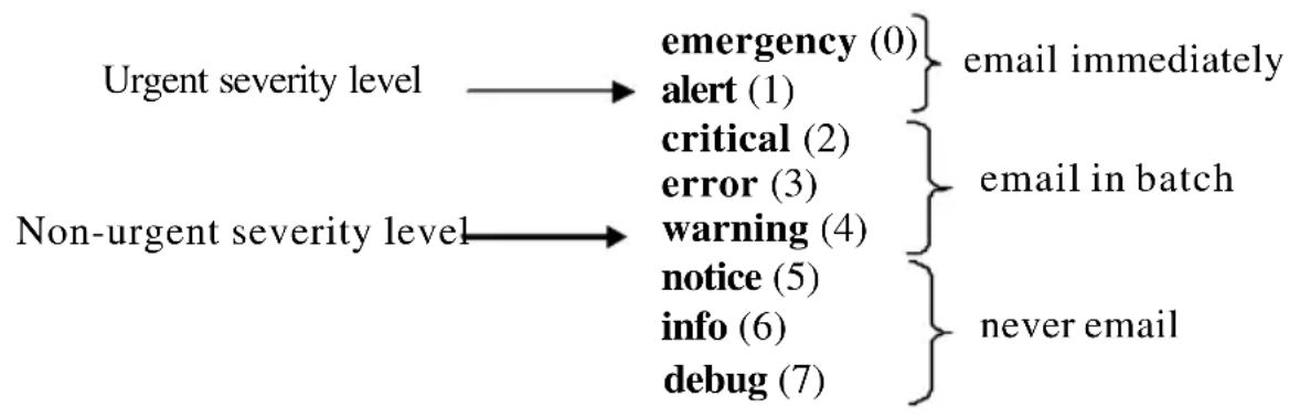
flowchart
graph LR
    A["Urgent severity level"] --> B["emergency (0)"]
    A --> C["alert (1)"]
    A --> D["critical (2)"]
    A --> E["error (3)"]
    A --> F["warning (4)"]
    A --> G["notice (5)"]
    A --> H["info (6)"]
    A --> I["debug (7)"]
    B --> J["email immediately"]
    D --> K["email in batch"]
    F --> L["never email"]
    G --> M[" "]
    H --> N[" "]
    I --> O[" "]
The network operator can adjust the urgent and non-urgent severity levels. These levels are global and apply to all destination e-mail addresses. Log messages in the urgent group are sent immediately to SMTP server with each log message in a separate mail. Log messages in the non-urgent group are batched into a single e-mail message and after a configurable delay.
Only the minimum part (MUA functionality of RFC 4409) required by the switch or router to send the messages to the SMTP server is supported. Some SMTP servers insist on authentication before the messages may be received by them. The minimum part (MUA functionality of RFC 4954) required by the switch or router to become authenticated by the SMTP server is supported. Only plain text authentication is supported.
Commands in this Chapter
This chapter explains the following commands:
| logging email show logging email statistics |
| logging cmail urgent clear logging cmail statistics |
| logging traps security |
| logging email message-type to-addr mail-server ip-address | hostname |
| logging email from-addr port (Mail Server Configuration Mode) |
| logging email message-type subject username (Mail Server Configuration Mode) |
| logging email logtime password (Mail Server Configuration Mode) |
| logging email test message-type show mail-server |
logging email
Use the logging email command in Global Configuration mode to enable e-mail alerting and set the lowest severity level for which log messages are e-mailed. Use the no form of the command to disable e-mail alerting.
Syntax
logging email [severity]
no logging email
Parameter Description
| Parameter Description | |
| severity If you specify | a severity level, log messages at or above the severity level are e-mailed. The severity level may either be specified by keyword or as an integer from 0 to 7. The accepted keywords, and the numeric severity level each represents, are as follows.·emergency (0)·alert (1)·critical (2)·error (3)·warning (4)·notice (5)·info (6)·debug (7) |
Default Configuration
E-mail alerting is disabled by default. When e-mail alerting is enabled, log messages at or above severity Warning are e-mailed.
Command Mode
Global Configuration mode
User Guidelines
The logging email command with no arguments enables e-mail alerting. Specify a severity to set the severity level of log messages that are e-mailed in a non-urgent manner. Log messages at or above this severity level, but below the urgent severity level, are collected together until the log time expires (the time specified in the logging email logtime command) and then e-mailed in a single e-mail message. If you set the non-urgent severity level to the same value as the urgent severity level, then no log messages are e-mailed non-urgently. See the logging email urgent command to specify the urgent severity level. The command no logging email disables all e-mail alerting.
logging email urgent
Use the logging email urgent command in Global Configuration mode to set the lowest severity level at which log messages are e-mailed in an urgent manner. To revert the urgent severity level to its default value, use the no form of this command.
Syntax
logging email urgent {severity | none}
no logging email urgent
Parameter Description
| Parameter Description | |
| severity Log messages | at or above this severity level are e-mailedimmediately. The severity level may either be specified bykeyword or as an integer from 0 to 7. The accepted keywords,and the numeric severity level each represents, are as follows.· emergency (0)· alert (1)· critical (2)· error (3)· warning (4)· notice (5)· info (6)· debug (7) |
| none If you specify this keyword, no log messages are e-mailedurgently. All log messages at or above the non-urgent level(configured with the logging email command) are e-mailed inbatch. | |
Default Configuration
The default severity level is alert.
Command Mode
Global Configuration mode
User Guidelines
Log messages at or above this severity level are considered urgent. By default, Emergency and Alert log messages are considered urgent. Urgent log messages are e-mailed immediately, one log message per e-mail message, and do not wait for the log time to expire. Urgent log messages are not e-mailed unless you enable e-mail alerting with the logging email command.
logging traps
Use the logging traps command in Global Configuration mode to set the lowest severity level at which SNMP traps are logged. To revert the urgent severity level to its default value, use the no form of this command.
Syntax
logging traps severity
no logging traps
Parameter Description
| Parameter Description | |
| severity The severity level at which SNMP traps are logged. The severity level may either be specified by keyword or as an integer from 0 to 7. The accepted keywords, and the numeric severity level each represents, arc as follows: ·emergency (0) ·alert (1) ·critical (2) ·error (3) ·warning (4) ·notice (5) ·info (6) ·debug (7) | |
Default Configuration
The default severity level is info(6).
Command Mode
Global Configuration mode
User Guidelines
You can filter log messages that appear in the buffered log by severity level. You can specify the severity level of log messages that are e-mailed. You can use this command to specify the severity level at which SNMP traps are logged, and thus control whether traps appear in the buffered log or are e-mailed and, if they are e-mailed, whether traps are considered urgent or non-urgent.
logging email message-type to-addr
Use the logging email message-type to-addr command in Global Configuration mode to configure the To address field of the e-mail. The message types supported now are urgent, non-urgent, and both. For each supported severity level, multiple e-mail addresses can be configured. For example, for urgent type of messages, there could be multiple addresses configured.
Syntax
logging email message-type {urgent | non-urgent | both} to-addr to-email- addr
no logging email to-addr to-addr message-type
no logging email message-type {urgent | non-urgent | both} to-addr to-email-addr
Parameter Description
This command does not require a parameter description.
Default Configuration
This command has no default configuration.
Command Mode
Global Configuration
User Guidelines
This command removes the configured to-addr field of e-mail.
logging email from-addr
Use the logging email from-addr command in Global Configuration mode to configure the From address of the e-mail. Use the no form of this command to remove the e-mail source address.
Syntax
logging email from-addr from-email-addr
no logging email from-addr
Parameter Description
This command does not require a parameter description.
Default Configuration
This command has no default configuration.
Command Mode
Global Configuration
User Guidelines
There are no user guidelines for this command.
logging email message-type subject
Use the logging email message-type subject command in Global Configuration mode to configures subject of the e-mail. Use the no form of this command to remove the existing subject and return to the default subject.
Syntax
logging email message-type message-type subject subject no logging email message-type message-type subject
Parameter Description
This command does not require a parameter description.
Default Configuration
This command has no default configuration.
Command Mode
Global Configuration
User Guidelines
The user must enter the message-type parameter manually as tab and space bar completion do not work for this parameter.
logging email logtime
Use the logging email logtime command in Global Configuration mode to configure the value of how frequently the queued messages are sent.
Syntax
logging email logtime time duration no logging email logtime
Parameter Description
| Parameter Description | |
| Time Duration Time | in minutes. Range: 30 – 1440. |
Default Configuration
The default value is 30 minutes.
Command Mode
Global Configuration
User Guidelines
This command has no user guidelines.
logging email test message-type
Use the logging email test message-type command in Global Configuration mode to test whether or not an e-mail is being sent to an SMTP server.
Syntax
logging email test message-type message-type message-body message-body
Parameter Description
| Parameter Description | |
| message-type Urgent, non-urgent, or both | |
| message-body The message to log. Enclose the message in double quotes if it contains any spaces. | |
Default Configuration
This command has no default configuration.
Command Mode
Global Configuration
User Guidelines
This command has no user guidelines.
show logging email statistics
Use the show logging email statistics command in Privileged EXEC mode to show the statistics about the e-mails. The command displays information on how many e-mails are sent, how many e-mails failed, when the last e-mail was sent, how long it has been since the last e-mail was sent, how long it has been since the e-mail changed to disabled mode.
Syntax
show logging email statistics
Parameter Description
This command does not require a parameter description.
Default Configuration
This command has no default configuration.
Command Mode
Privileged EXEC
User Guidelines
This command has no user guidelines.
clear logging email statistics
Use the clear logging email statistics command in Privileged EXEC mode to clear the e-mail alerting statistics.
Syntax
clear logging email statistics
Parameter Description
This command does not require a parameter description.
Default Configuration
This command has no default configuration.
Command Mode
Privileged EXEC
User Guidelines
This command has no user guidelines.
security
Use the security command in Mail Server Configuration mode to set the e-mail alerting security protocol. This enables and disables the switch to use TLS authentication with the SMTP Server. If the administrator sets the TLS mode and, if the SMTP sever does not support TLS mode, then no e-mail goes to the SMTP server.
Syntax
security {tls | none}
Parameter Description
This command does not require a parameter description.
Default Configuration
The default value is disabled.
Command Mode
Mail Server Configuration
User Guidelines
This command has no user guidelines.
mail-server ip-address | hostname
Use the mail-server ip-address | hostname command in Global Configuration mode to configure the SMTP server IP address and change the mode to Mail Server Configuration mode. The server address can be in the IPv4, IPv6, or DNS name format. Use the no form of this command to remove the configured SMTP server address.
Syntax
mail-server {ip-address ip-address | hostname hostname}
no mail-server {ip-address | hostname}
Parameter Description
| Parameter Description | |
| ip-address An IPv4 or IPv6 address. | |
| hostname The DNS name of an SMTP server. |
Default Configuration
The default configuration for a mail server is shown in the table below.
| Field Default | |
| Email Alert Mail Server Port 25 | |
| Email Alert Security Protocol none | |
| Email Alert Username admin | |
| Email Alert Password admin |
Command Mode
Global Configuration
User Guidelines
This command has no user guidelines.
port (Mail Server Configuration Mode)
Use the port command in Mail Server Configuration mode to configure the TCP port to use for communication with the SMTP server. Port can be set to 465 or 25. Use the no form of the command to revert the SMTP port to the default port.
Syntax
port port
no port
Parameter Description
This command does not require a parameter description.
Default Configuration
The default value is 25.
Command Mode
Mail Server Configuration
User Guidelines
Port 25 is the standard SMTP port for cleartext messages. Port 465 is the standard port for messages sent using TLSv1. Messages are always sent in plain text mode.
username (Mail Server Configuration Mode)
Use the username command in Mail Server Configuration mode to configure the username required by the authentication. Use the no form of the command to revert the username to the default value.
Syntax
username username
no username
Parameter Description
This command does not require a parameter description.
Default Configuration
The default value for username is admin.
Command Mode
Mail Server Configuration
User Guidelines
This command has no user guidelines.
password (Mail Server Configuration Mode)
Use the password command in Mail Server Configuration mode to configure the password required to authenticate to the e-mail server. Use the no form of the command to revert the password to the default value.
Syntax
password password
no password
Parameter Description
This command does not require a parameter description.
Default Configuration
The default value for password is admin.
Command Mode
Mail Server Configuration
User Guidelines
This command has no user guidelines.
show mail-server
Use the show mail-server command in Privileged EXEC mode to display the configuration of all the mail servers or a particular mail server.
Syntax
show mail-server {ip-address | hostname | all}
Parameter Description
This command does not require a parameter description.
Default Configuration
This command has no default configuration.
Command Mode
Privileged EXEC, Config mode and all Config sub-modes
User Guidelines
This command has no user guidelines.
Example
console#show mail-server all
Mail Servers configuration:
No of mail servers configured:2
Mail Serqy ver1 configuration:
SMTP server IP Address: 10.131.1.11
SMTP server Port: 465
SMTP server security protocol: tls
SMTP server authentication details:
Username: admin
Mail server2 configuration:
SMTP server IP Address: 10.131.1.31
SMTP server Port: 465
SMTP server security protocol: tls
SMTP server authentication details:
Username: admin
console#show mail-server ip-address 10.131.1.11
SMTP server IP Address: 10.131.1.11
SMTP server Port: 465
SMTP server security protocol: tls
SMTP server authentication details:
Username: admin
Ethernet Configuration Commands
PowerConnect switches support a variety of configuration options to optimize network operations. Features such as flow-control and jumbo frames are supported along with a variety of commands to display traffic statistics as well as limit the effects of network loops or other network issues.
Jumbo frame technology is employed in certain situations to reduce the task load on a server CPU and to transmit large amounts of data efficiently. Jumbo frames technology predominantly appears where certain applications would benefit from using a larger frame size, e.g. Network File System (NFS). The larger frame size eliminates some of the need for fragmentation, leading to greater throughput. The increase in throughput is particularly valuable on data center servers where the larger frame size increases efficiency of the system and allows processing of more requests. The PowerConnect jumbo frames feature extends the standard ethernet MTU (Max Frame Size) from 1518 (1522 with VLAN header) bytes to 9216 bytes. However, any device connecting to the same broadcast domain should support the same or larger MTU.
Flow control is a mechanism or protocol used to temporarily suspend transmission of data to a device to avoid overloading the device receive path. PowerConnect switching implements the flow control mechanism defined in IEEE 802.3 Annexes 31A and 31B (formerly IEEE 802.3x). PowerConnect switching is able to transmit a MAC Control frame containing the PAUSE opcode to halt transmission by the device receiving the PAUSE frame whenever internal congestion is detected by the switching fabric. Flow control is enabled by default for all ports.
Storm control allows for rate limiting of specific types of packets through the forwarding plane. The administrator can configure the absolute rate in packets-per-second for the Storm control threshold. Each classified packet type (broadcast, multicast, or unicast) can be enabled/disabled per port, and the threshold level at which Storm-Control is active is also configurable per-port and per-type (as a percentage of interface speed).
On a storm control enabled interface, if the ingress rate of that type of packet (L2 broadcast, multicast, or unicast) is greater than the configured threshold level (as a percentage of port speed or as an absolute packets-per-second rate), the switch forwarding-plane discards the excess traffic.
The speed and duplex commands control interface link speeds and auto-negotiation. If either speed or duplex is set to something other than auto, auto-negotiation is disabled on the interface. Auto-negotiation will link at the highest possible speed supported on the interface and prefers full duplex over half duplex.
Commands in this Chapter
This chapter explains the following commands:
| clear counters show interfaces | speed |
| configuration | |
| description show interfaces counters storm-control broadcast | |
| duplex show interfaces description storm-control multicast | |
| flowcontrol show interfaces detail storm-control unicast | |
| interface show statistics switchport protected | |
| interface range show statistics switchport switchport protected name | |
| mtu | show storm-control show switchport protected |
| show interfaces advertise | shutdown |
clear counters
Use the clear counters command in Privileged EXEC mode to clear statistics on an interface.
Syntax
clear counters [{gigabitethernet unit/slot/port | port-channel port-channel-number | switchport | tengigabitethernet unit/slot/port }]
Default Configuration
This command has no default configuration.
Command Mode
Privileged EXEC mode
User Guidelines
Use of the clear counters command with no parameters indicates that both switch and all interface statistics are to be cleared.
Example
In the following example, the counters for port 1/0/1 are cleared.console#clear counters gigabitethernet 1/0/1
description
Use the description command in Interface Configuration mode to add a description to an interface. To remove the description use the no form of this command.
Syntax
description string
no description
- string — Comment or a description of the port attached to this interface. (Range: 1 to 64 characters)
Default Configuration
By default, the interface does not have a description.
Command Mode
Interface Configuration (gigabitethernet, port-channel, tengigabitethernet) mode
User Guidelines
This command has no user guidelines.
Example
The following example adds a description to the Ethernet port 5.
console(config)#interface gigabitethernet 1/0/5
console(config-if-1/0/5)# description RD_SW#3
duplex
Use the duplex command in Interface Configuration mode to configure the duplex operation of a given Ethernet interface. To restore the default, use the no form of this command.
Syntax
duplex {auto | half | full}
no duplex
Parameter Description
| Parameter Description | |
| auto Auto negotiation is enabled for the port. | |
| half Force half-duplex operation. | |
| full Force full-duplex operation. | |
Default Configuration
Auto-negotiation is enabled by default on copper ports.
Command Mode
Interface Configuration (Ethernet) mode
User Guidelines
When both speed and duplex are configured to auto, auto negotiation is enabled for the port. To disable auto-negotiation on a port, it is necessary to enter both the speed and duplex commands without using the auto
parameter. Fiber ports do not support auto-negotiation and therefore require the operator to enter the duplex full command and the speed command with the desired operating bandwidth. Disabling auto-negotiation on 1G copper ports may lead to random frame loss as the clock master has not been arbitrated by the auto-negotiation process. Auto-negotiation is required on 10G/40G copper ports, and is recommended on all copper ports.
Example
The following example configures the duplex operation of gigabit Ethernet port 1/0/5 to force full duplex operation.
console(config)# interface gigabitethernet 1/0/5
console(config-if)# duplex full
flowcontrol
Use the flowcontrol command in Global Configuration mode to configure the flow control. To disable flow control, use the no form of this command.
Syntax
flowcontrol
no flowcontrol
Default Configuration
Flow Control is enabled by default.
Command Mode
Global Configuration mode
User Guidelines
This command has no user guidelines.
Example
In the following example, flow control is enabled.
console(config)# flowcontrol
interface
Use this command to configure parameters for the gigabit Ethernet and ten-gigabit Ethernet ports, and for port-channels. While in Global Configuration mode, enter the interface command (with a specific interface). To exit to Global Configuration mode, enter exit. To return to Privileged EXEC mode, press Ctrl-Z or enter end.

Additional forms of the interface command enable configuring VLANs, tunnels, the loopback interface, the out-of-band interface, and ranges of interfaces. See interface vlan, interface tunnel, interface loopback, and interface range.
Syntax
interface {gigabitethernet unit/slot/port | port-channel port-channel-number | tengigabitethernet unit/slot/port }
Default Configuration
This command has no default configuration.
Command Mode
Global Configuration
Interface Configuration
User Guidelines
It is possible to enter interface configuration mode from global configuration mode or from interface configuration mode.
Example
The following example enables gigabit port 2 on stack member 1 for configuration.
console(config)# interface gigabitethernet 1/0/2
console (config-if)#
interface range
Use the interface range command in Global Configuration mode to execute a command on multiple ports at the same time.

NOTE: An additional form of this command enables configuring a range of VLANs.
See interface range vlan.
Syntax
interface range {port-range | port-typeall}
| Parameter Description | |
| port-range | A list of valid ports to configure. Separate non-consecutive ports with a comma and no spaces; use a hyphen to designate a range of ports. For more detailed information, see Operating on Multiple Objects (Range). The command line buffer parses up to the maximum number of command line characters possible in the port-range parameter. |
| port-type Shows all in | interfaces of the specified type. |
Default Configuration
This command has no default configuration.
Command Mode
Global Configuration, Interface Range and Interface modes
User Guidelines
Commands under the interface range context are executed independently on each active interface in the range. If the command returns an error on one of the active interfaces, it does not stop executing commands on other active interfaces.
Example
The following example shows how gigabitethernet ports 5/0/18 to 5/0/20 and 3/0/1 to 3/0/24 are ranged to receive the same command.
console(config)# interface range gigabitethernet 5/0/18-20,3/0/1-24
console(config-if-range)#
The following example shows how all gigabitethernet ports can be configured at once.
console(config)# interface range gigabitethernet all console(config-if-range)#
The following examples demonstrate various valid interface ranges:
console(config)#interface range gigabitEthernet 1/0/1-20
console(config)#interface range gi1/0/20-48
console(config)#interface range gi1/0/1,gi1/0/48
console(config)#interface range gi2/0/1-10,gi1/0/30
console(config)#interface range gi1/0/1-10,gi1/0/30-48
console(config)#interface range gi1/0/1,te1/1/1
console(config)#interface range gigabitEthernet 1/0/10,tengigabitEthernet 1/1/2
mtu
Use the mtu command in Interface Configuration mode to set the maximum transmission unit on an interface by adjusting the maximum size of received Ethernet frames. To return to the default setting, use the no form of this command.
Syntax
mtu bytes
no mtu
• bytes — Number of bytes (Range: 1518-9216)
Default Configuration
The default number of bytes is 1518 (1522 bytes of VLAN-tagged frames).
Command Mode
Interface Configuration (Ethernet, Port-channel) mode
User Guidelines
Because the switch does not fragment frames, received frames that are larger than the MTU setting are dropped. Packets originated by the CPU are fragmented on transmission if the link MTU is smaller than the IP MTU. Setting the MTU less than the IPv4 MTU causes CPU-generated IPv4 packets to be fragmented. Setting the MTU less than the IPv6 MTU causes CPU-generated IPv6 packets to be dropped. Setting the MTU also automatically adjusts the IPv4 MTU. Port-channel and interface MTU settings are configured and maintained independently. Setting the MTU on a port-channel adjusts the operational MTU of an interface when the interface is a member of a LAG. The operational MTU is reset back to the interface MTU setting when the interface leaves the LAG.
Use the show interfaces mtu command to show the interface MTU.
Example
The following example of the mtu command increases maximum packet size to 9216 bytes.
console(config-if-1/0/5)#mtu 9216
show interfaces advertise
Use the show interfaces advertise command in Privileged EXEC mode to display information about auto-negotiation advertisement. The display includes the local configuration and link partner advertisement, in addition to the local advertisement.
Syntax
show interfaces advertise [{gigabitethernet unit/slot/port | tengigabitethernet unit/slot/port }]
Default Configuration
This command has no default configuration.
Command Mode
Privileged EXEC mode, Config mode and all Config sub-modes
User Guidelines
The priority resolution field indicates the auto-negotiated link speed and duplex. The clock field indicates whether the local interface has auto-negotiated to clock master or clock slave. When the link is down, the field will show No link.
When the link is down, the Oper Peer Advertisement and Priority Resolution fields will show dashes.
Examples
The following examples display information about auto negotiation advertisement.
Example #1
console#show interfaces advertise
| Port | Type | Neg | Operational Link Advertisement |
| 1/0/2 | 1G-Copper | Enable | 1000f, 100f, 100h, 10f, 10h |
| 1/0/2 | 1G-Copper | Enable | 1000f |
Example #2
| console# show interfaces advertise gigabitethernet 1/0/1 |
| Port: Gigabitethernet 1/0/1 |
| Type: 1G-Copper |
| Link state: Up |
| Auto negotiation: enabled |
| 10h 10f 100h 100f 1000f |
| Admin Local Link ---- ---- ---- ---- |
| Advertisement yes yes yes yes no |
Example #3
console#show interfaces advertise gi1/0/1
Port: Gi1/0/1
Type: Gigabit - Level
Link State: Down
Auto Negotiation: Enabled
802.3az EEE: Disabled
Clock: Master
| 1000f | 1000h | 100f | 100h | 10f | 10h | |
| Admin Local Link Advertisement | no | no | yes | no | yes | no |
| Oper Local Link Advertisement | no | no | yes | no | yes | no |
| Oper Peer Advertisement | no | no | yes | yes | yes | yes |
| Priority Resolution | - | - | yes | - | - | - |
show interfaces configuration
Use the show interfaces configuration command in User EXEC mode to display the configuration for all configured interfaces.
Syntax
show interfaces configuration [{gigabitethernet unit/slot/port | port-channel port-channel-number | tengigabitethernet unit/slot/port}]
Default Configuration
This command has no default configuration.
Command Mode
User EXEC mode, Config mode and all Config sub-modes
User Guidelines
This command has no use guidelines.
Example
The following example displays the configuration for all configured interfaces:
console>show interfaces configuration
| Port | Type | Duplex | Speed | Neg | Admin State |
| 1/0/1 | Gigabit - Level | Full | 100 | Auto | Up |
| 1/0/2 | Gigabit - Level | N/A | Unknown | Auto | Up |
| 1/0/3 | Gigabit - Level | N/A | Unknown | Auto | Up |
| 1/0/4 | Gigabit - Level | N/A | Unknown | Auto | Up |
| 1/0/5 | Gigabit - Level | N/A | Unknown | Auto | Up |
| 1/0/6 | Gigabit - Level | N/A | Unknown | Auto | Up |
| 1/0/7 | Gigabit - Level | N/A | Unknown | Auto | Up |
| 1/0/8 | Gigabit - Level | N/A | Unknown | Auto | Up |
| 1/0/9 | Gigabit - Level | N/A | Unknown | Auto | Up |
| 1/0/10 | Gigabit - Level | N/A | Unknown | Auto | Up |
| 1/0/11 | Gigabit - Level | N/A | Unknown | Auto | Up |
| 1/0/12 | Gigabit - Level | N/A | Unknown | Auto | Up |
| 1/0/13 | Gigabit - Level | N/A | Unknown | Auto | Up |
| 1/0/14 | Gigabit - Level | N/A | Unknown | Auto | Up |
| 1/0/15 | Gigabit - Level | N/A | Unknown | Auto | Up |
| 1/0/16 | Gigabit - Level | N/A | Unknown | Auto | Up |
| 1/0/17 | Gigabit - Level | N/A | Unknown | Auto | Up |
| 1/0/18 | Gigabit - Level | N/A | Unknown | Auto | Up |
| 1/0/19 | Gigabit - Level | N/A | Unknown | Auto | Up |
| --More-- or (q)uit | |||||
The displayed port configuration information includes the following:
| Field Description | |
| Port The port number. | |
| Port Type The | port designated IEEE shorthand identifier. For example 1000Base-T refers to 1000 Mbps baseband signaling including both Tx and Rx transmissions. |
| Duplex Displays the port Duplex status. | |
| Speed Refers to the port speed. | |
| Neg Describes | the Auto-negotiation status. |
| Admin State Displays whether the port is enabled or disabled. | |
show interfaces counters
Use the show interfaces counters command in either User EXEC mode or Privileged EXEC mode to display Priority Flow Control (PFC) traffic seen by the interface, including Received PFC Frames and Transmitted PFC Frames for a given ethernet or port-channel interface.
Syntax
show interfaces counters [gigabitethernet unit/slot/port | port-channel port-channel-number | tengigabitethernet unit/slot/port ]
Default Configuration
This command has no default configuration.
Command Mode
User EXEC mode, Privileged EXEC mode, Config mode and all Config sub-modes
User Guidelines
This command has no user guidelines.
Example
The following example displays traffic seen by the physical interface:
console>show interfaces counters
Port InOctets InUcastPkts
| 1/0/1 | 183892 | 1289 |
| 3/0/1 | 123899 | 1788 |
| Port | OutOctets | OutUcastPkts |
| 1/0/1 | 9188 | 9 |
| 2/0/1 | 0 | 0 |
| 3/0/1 | 8789 | 27 |
| Ch | InOctets | InUcastPkts |
| 1 | 27889 | 928 |
| Ch | OutOctets | OutUcastPkt |
| 1 | 23739 | 882 |
The following example displays counters for Ethernet port 1/0/1.
console(config-if-Tel/0/1)#show interfaces counters tel/0/1
| Port | InOctets | InUcastPkts | InMcastPkts | InBcastPkts |
| Tel/0/1 | 0 | 0 | 0 | 0 |
| Port | OutOctets | OutUcastPkts | OutMcastPkts | OutBcastPkts |
| Tel/0/1 | 0 | 0 | 0 | 0 |
| FCS Errors: | 0 |
| Single Collision Frames: | 0 |
| Late Collisions: | 0 |
| Excessive Collisions: | 0 |
| Multiple Collisions: | 0 |
| Oversize Packets: | 0 |
| Internal MAC Rx Errors: | 0 |
| Received Pause Frames: | 0 |
| Transmitted Pause Frames: | 0 |
| Received PFC Frames: | 0 |
| Transmitted PFC Frames: | 0 |
The following table describes the fields shown in the display:
| Field Description | |
| InOctets Counted received octets. | |
| InUcastPkts Counted received Unicast packets. | |
| InMcastPkts Counted received Multicast packets. | |
| InBcastPkts Counted received Broadcast packets. | |
| OutOctets Counted transmitted octets. | |
| OutUcastPkts Counted transmitted Unicast packets. | |
| OutMcastPkts Counted transmitted Multicast packets. | |
| OutBcastPkts Counted transmitted Broadcast packets. | |
| Alignment Errors A count of frames received that are not an integral number of octets in length and do not pass the FCS check. | |
| FCS Errors Counted frames received that are an integral number of octets in length but do not pass the FCS check. | |
| Single Collision Frames Counted frames that are involved in a single collision, and are subsequently transmitted successfully. | |
| Multiple Collision Frames | A count of frames that are involved in a multiple collision, and arc subsequently transmitted successfully |
| Deferred Transmissions | A count of frames for which the first transmission attempt is delayed because the medium is busy |
| Late Collisions Counted | times that a collision is detected later than one slot time into the transmission of a packet. |
| Excessive Collisions Counted | frames for which transmission fails due to excessive collisions. |
| Oversize Packets Counted | frames received that exceed the maximum permitted frame size. |
| Internal MAC Rx Errors | A count of frames for which reception fails due to an internal MAC sublayer receive error. |
| Received Pause Frames A | count of MAC Control frames received with an opcode indicating the PAUSE operation. |
| Transmitted Pause Frames | Counted MAC Control frames transmitted on this interface with an opcode indicating the PAUSE operation. |
| Received PFC Frames A | count of the received Priority Flow Control (PFC) frames. |
| Transmitted PFC Frames | A count of the transmitted PFC frames. |
show interfaces description
Use the show interfaces description command in User EXEC mode to display the description for all configured interfaces.
Syntax
show interfaces description [gigabitethernet unit/slot/port | port-channel port-channel-number| tengigabitethernet unit/slot/port]
Default Configuration
This command has no default configuration.
Command Mode
User EXEC mode, Config mode and all Config sub-modes
User Guidelines
This command has no user guidelines.
Example
The following example displays the description for all interfaces.
console>show interfaces description
Port Description
1/0/1 Port that should be used for management only
2/0/1
2/0/2
Ch Description
1 Output
show interfaces detail
Use the show interfaces detail command in Privileged EXEC mode to display detailed status and configuration of the specified interface.
Syntax
show interfaces detail
| Field Description | |
| interface-id A | physical interface or port channel identifier. |
Default Configuration
This command has no default configuration.
Command Mode
Privileged EXEC mode, Config mode and all Config sub-modes
User Guidelines
This command has no user guidelines.
Example
The following example displays detailed status and configuration of the specified interface.
console#show interfaces detail gi1/0/1
| Port Type | Duplex | Speed | Neg | Admin State | Link State |
| Gi1/0/1Gigabit - Level | N/A | Unknown | Auto | Up | Down |
Port Description
Gi1/0/1
Flow Control: Enabled
Port: Gi1/0/1
VLAN Membership mode: Access Mode
Operating parameters:
PVID: 1
Ingress Filtering: Enabled
Acceptable Frame Type: Untagged
Default Priority: 0
GVRP status:Disabled
Protected: Disabled
Port Gi1/0/1 is member in:
| VLAN | Name | Egress rule | Type |
| 1 | default | Untagged | Default |
Static configuration:
PVID: 1
Ingress Filtering: Enabled
Acceptable Frame Type: Untagged
Port Gi1/0/1 is statically configured to:
VLAN Name
Egress rule
Forbidden VLANS:
VLAN Name
Port Gi1/0/1 Enabled
State: Disabled
Role: Disabled
Port id: 128.1
Port Cost: 0
Port Fast: No (Configured: no)
Root Protection: No
Designated bridge Priority: 32768
Address: 001E.C9AA.AF51
Designated port id: 128.1
Designated path cost: 40000
CST Regional Root: 80:00:00:1E:C9:AA:AF:51
CST Port Cost: 0
BPDU: sent 121, received 316356
show interfaces status
Use the show interfaces status command in Privileged EXEC mode to display the status for all configured interfaces.
Syntax
show interfaces status
The displayed port status information includes the following:
| Field Description | |
| Port | The port or port channel number. Oob means Out-of-Band Management Interface. |
| Description Description of the port. | |
| Duplex Displays the port Duplex status. | |
| Speed Refers to the port speed. | |
| Neg Describes the Auto-negotiation status. | |
| Link State | Displays the Link Aggregation status, either Up or Down. |
| Flow Control Status | Displays the Flow Control status, either Active or Inactive. |
Default Configuration
This command has no default configuration.
Command Mode
Privileged EXEC mode, Config mode and all Config sub-modes
User Guidelines
Port channels are only displayed if configured. Use the show interfaces port-channel command to display configured and unconfigured port channels. Interfaces configured as stacking ports will show as detached in the output of the show interfaces status command.
Example
The following example displays the status for all configured interfaces.
console#show interfaces status
| Port | Description | Duplex | Speed | Neg | Link State | Flow Status | Control | |
| Tel/0/1 | N/A | Unknown | ||||||
| Tel/0/2 | N/A | Unknown | Auto | Down | Inactive | |||
| Tel/0/3 | phone port N/A | Unknown | Auto Down Inactive | |||||
show statistics
Use the show statistics command in Privileged EXEC mode to display detailed statistics for a specific port or for the entire switch.
Syntax
show statistics {gigabitethernet unit/slot/port | switchport | port-channel port-channel-number | tengigabitethernet unit/slot/port }
Parameter Description
| Parameter Description | |
| unit/slot/port | A valid interface. See Interface Naming Conventions for interface representation. |
| switchport Displays statistics for the entire switch. | |
Default Configuration
This command has no default configuration.
Command Mode
Privileged EXEC mode, Config mode and all Config sub-modes
User Guidelines
This command has no user guidelines.
Examples
The following example shows statistics for port 1/0/1.
console(config-if-Te1/0/1)#show statistics te1/0/1
Total Packets Received (Octets).... 0
Packets Received 64 Octets.... 0
Packets Received 65-127 Octets....0
Packets Received 128-255 Octets....0
Packets Received 256-511 Octets....0
Packets Received 512-1023 Octets.... 0
Packets Received 1024-1518 Octets.... 0
Packets Received > 1518 Octets..... 0
Packets RX and TX 64 Octets.... 0
Packets RX and TX 65-127 Octets....0
Packets RX and TX 128-255 Octets....0
Packets RX and TX 256-511 Octets....0
Packets RX and TX 512-1023 Octets.... 0
Packets RX and TX 1024-1518 Octets.... 0
Packets RX and TX 1519-2047 Octets.... 0
Packets RX and TX 2048-4095 Octets.... 0
Packets RX and TX 4096-9216 Octets.... 0
Total Packets Received Without Errors...... 0
Unicast Packets Received.... 0
Multicast Packets Received.... 0
Broadcast Packets Received.... 0
Total Packets Received with MAC Errors..... 0
Jabbers Received.... 0
Fragments/Undersize Received.... 0
Alignment Errors.... 0
FCS Errors.... 0
Overruns.... 0
Total Received Packets Not Forwarded.... 0
802.3x Pause Frames Received.... 0
Unacceptable Frame Type.... 0
Total Packets Transmitted (Octets).... 0
Packets Transmitted 64 Octets....0
Packets Transmitted 65-127 Octets....0
Packets Transmitted 128-255 Octets....0
Packets Transmitted 256-511 Octets....0
Packets Transmitted 512-1023 Octets..... 0
Packets Transmitted 1024-1518 Octets..... 0
Packets Transmitted > 1518 Octets..... 0
Max Frame Size.... 1518
Total Packets Transmitted Successfully.... 0
Unicast Packets Transmitted.... 0
Multicast Packets Transmitted.... 0
Broadcast Packets Transmitted.... 0
Total Transmit Errors.... 0
Total Transmit Packets Discarded.... 0
Single Collision Frames.... 0
Multiple Collision Frames.... 0
Excessive Collision Frames.... 0
802.3x Pause Frames Transmitted.... 0
GVRP PDUs received.... 0
GVRP PDUs Transmitted.... 0
GVRP Failed Registrations.... 0
BPDU: sent 0, received 0
EAPOL Frames Transmitted.... 0
EAPOL Start Frames Received.... 0
Time Since Counters Last Cleared.... 0 day 13 hr 20 min 24 sec
show statistics switchport
Use the show statistics command in Privileged EXEC mode to display detailed statistics for a specific port or for the entire switch.
Syntax
show statistics {interface-id | switchport}
Parameter Description
| Parameter Description | |
| interface-id Interface | id. See Interface Naming Conventions for interface representation. |
| switchport Displays | statistics for the entire switch. |
Default Configuration
This command has no default configuration.
Command Mode
Privileged EXEC mode, Config mode and all Config sub-modes
User Guidelines
It is possible to enter interface configuration mode from global configuration mode or from interface configuration mode.
Example
The following example shows statistics for the entire switch.
console#show statistics switchport
Total Packets Received (Octets).... 0
Packets Received Without Error.... 0
Unicast Packets Received.... 0
Multicast Packets Received.... 0
Broadcast Packets Received.... 0
Receive Packets Discarded.... 0
Octets Transmitted.... 0
Packets Transmitted Without Errors...... 0
Unicast Packets Transmitted.... 0
Multicast Packets Transmitted.... 0
Broadcast Packets Transmitted.... 0
Transmit Packets Discarded.... 0
Most Address Entries Ever Used.... 3
Address Entries Currently in Use.... 3
Maximum VLAN Entries.... 1024
Most VLAN Entries Ever Used.... 2
Static VLAN Entries.... 2
Dynamic VLAN Entries.... 0
VLAN Deletes.... 0
Time Since Counters Last Cleared.... 0 day 18 hr 1 min 59 sec
show storm-control
Use the show storm-control command in Privileged EXEC mode to display the configuration of storm control.
Syntax
show storm-control [all | {gigabitethernet unit/slot/port | tengigabitethernet unit/slot/port }]
Default Configuration
This command has no default configuration.
Command Mode
Privileged EXEC mode, Config mode and all Config sub-modes
User Guidelines
This command has no user guidelines.
Examples
The following example shows storm control configurations for all valid Ethernet ports. The second example shows flow control mode status.
console#show storm-control all
| Bcast | Bcast | Mcast | Mcast | Ucast | Ucast | |
| Intf | Mode | Level | Mode | Level | Mode | Level |
console#show storm-control
802.3x Flow Control Mode..... Disable
shutdown
Use the shutdown command in Interface Configuration mode to disable an interface. To restart a disabled interface, use the no form of this command.
Syntax
shutdown
no shutdown
Default Configuration
The interface is enabled.
Command Mode
Interface Configuration (Ethernet, Port-Channel, Tunnel, Loopback) mode
User Guidelines
This command has no user guidelines.
Examples
The following example disables gigabit Ethernet port 1/0/5.
console(config)#interface gigabitethernet 1/0/5
console(config-if-1/0/5)# shutdown
The following example re-enables gigabit ethernet port 1/0/5.
console(config)#interface gigabitethernet 1/0/5
console(config-if-1/0/5)# no shutdown
speed
Use the speed command in Interface Configuration mode to configure the speed of a given Ethernet interface. To restore the default, use the no form of this command.
Syntax
speed {10 | 100 | 1000 | 10000 | auto [10 | 100 | 1000 | 10000]}
no speed
Parameter Description
| Parameter Description | |
| 10 Configures the port to 10 Mbps operation. | |
| 100 Configures the port to 100 Mbps operation. | |
| 1000 Configures the port to 1000 Mbps operation. | |
| 10000 Configures the port to 10 Gbps operation. | |
| 40000 Configures the port to 40 Gbps operation. | |
| auto The port automatically detects the speed it should run based on the port at the other end of the link. If you use the 10, 100, or 1000 keywords with the auto keyword, the port only negotiates at the specified speeds. | |
Default Configuration
Auto-negotiation is enabled by default on copper ports.
Command Mode
Interface Configuration (Ethernet) mode
User Guidelines
To disable auto-negotiation on a port, it is necessary to enter both the speed and duplex commands without using the auto parameter. Fiber ports do not support auto-negotiation and therefore require the operator to enter both the duplex full command and the speed command with the desired operating bandwidth. Disabling auto-negotiation on 1G copper ports may lead to random frame loss as the clock master has not been arbitrated by the auto-negotiation process. Auto-negotiation is required on 10G/40G copper ports, and is always recommended for copper ports. When the auto parameter is used with a set of speeds, only those speeds are advertised during auto-negotiation. Alternatively, if no speed arguments are configured, then all the speeds which the port is capable of supporting are advertised. Not all ports
support all speeds, even if they are available in the command. Entering an unsupported speed will produce the following error message An invalid interface has been used for this function. Fiber ports do not support auto-negotiation. Both ends of fiber connections must be set to full-duplex and the same speed.
Example
The following example configures the speed operation of Ethernet port 1/0/5 to advertise 100-Mbps operation only.
console(config)#interface gigabitethernet 1/0/5
console(config-if)#speed 100
storm-control broadcast
Use the storm-control broadcast command in Interface Configuration mode to enable broadcast storm recovery mode for a specific interface. If the mode is enabled, broadcast storm recovery is active, and if the rate of L2 broadcast traffic ingressing on an interface increases beyond the configured threshold, the traffic will be dropped. Therefore, the rate of broadcast traffic will be limited to the configured threshold.
Syntax
storm-control broadcast [level | rate]
no storm-control broadcast
• level— The configured rate as a percentage of link-speed.
- rate — The configured rate in kilobits per second (kbps). (Range: 0-100)
Default Configuration
The default value is 5.
Command Mode
Interface Configuration (Ethernet) mode
User Guidelines
This command has no user guidelines.
Example
console(config-if-1/0/1)#storm-control broadcast level 5
storm-control multicast
Use the storm-control multicast command in Interface Configuration mode to enable multicast storm recovery mode for an interface. If the mode is enabled, multicast storm recovery is active, and if the rate of L2 multicast traffic ingressing on an interface increases beyond the configured threshold, the traffic will be dropped. Therefore, the rate of multicast traffic will be limited to the configured threshold.
When you use the no storm-control multicast command to "disable" storm-control after having set the level or rate to a non-default value, that value is still set but is not active until you re-enable storm-control.
Syntax
storm-control multicast [level | rate]
no storm-control multicast
• level— The configured rate as a percentage of link-speed.
• rate — The configured rate in kilobits per second (kbps). (Range: 0-100)
Default Configuration
The default value is 5.
Command Mode
Interface Configuration (Ethernet) mode
User Guidelines
This command has no user guidelines.
Example
console(config-if-1/0/1)#storm-control multicast level 5
storm-control unicast
Use the storm-control unicast command in Interface Configuration mode to enable unknown unicast storm control for an interface. If the mode is enabled, unicast storm recovery is active, and if the rate of unknown L2 unicast (destination lookup failure) traffic ingressing on an interface increases beyond the configured threshold, the traffic will be dropped. Therefore, the rate of unknown unicast traffic will be limited to the configured threshold.
When you use the no storm-control multicast command to "disable" storm-control after having set the level or rate to a non-default value, that value is still set but is not active until you re-enable storm-control.
Syntax
storm-control unicast [level | rate]
no storm-control unicast
• level— The configured rate as a percentage of link-speed.
- rate — The configured rate in kilobits per second (kbps). (Range: 0-100)
Default Configuration
The default value is 5.
Command Mode
Interface Configuration (Ethernet) mode
User Guidelines
This command has no user guidelines.
Example
console(config-if-1/0/1)#storm-control unicast level 5
switchport protected
Use the switchport protected command in Interface Configuration mode to configure a protected port. The groupid parameter identifies the set of protected ports to which this interface is assigned. You can only configure an interface as protected in one group. You are required to remove an interface from one group before adding it to another group.
Port protection occurs within a single switch. Protected port configuration does not affect traffic between ports on two different switches. No traffic forwarding is possible between two protected ports. Ports in a protected group will not forward traffic to other ports in the group.
Syntax
switchport protected groupid
no switchport protected
- groupid--Identifies which group this port will be protected in. (Range: 0-2)
Default Configuration
No protected switchports are defined.
Command Mode
Interface Configuration (Ethernet) mode
User Guidelines
This command has no user guidelines.
Example
The following example configures Ethernet port 1/0/1 as a member of protected group 1.
console(config)#interface gigabitethernet 1/0/1
console(config-if-1/0/1)#switchport protected 1
switchport protected name
Use the switchport protected name command in Global Configuration mode to adds the port to the protected group 1 and also sets the group name to "protected".
Syntax
switchport protected groupidname name
no switchport protected groupid name
- groupid — Identifies which group the port is to be protected in.
(Range: 0–2)
• name — Name of the group. (Range: 0-32 characters)
Default Configuration
This command has no default configuration.
Command Mode
Global Configuration mode
User Guidelines
This command has no user guidelines.
Example
The following example assigns the name "protected" to group 1.
console(config-if-1/0/1)#switchport protected 1 name protected
show switchport protected
Use the show switchport protected command in Privileged EXEC mode to display the status of all the interfaces, including protected and unprotected interfaces.
Syntax
show switchport protected groupid
- groupid — Identifies which group the port is to be protected in. (Range: 0–2)
Default Configuration
This command has no default configuration.
Command Mode
Privileged EXEC mode, Config mode and all Config sub-modes
User Guidelines
This command has no user guidelines.
Example
The following example identifies test as the protected group.
console#show switchport protected 0
Name...... test
Ethernet CFM Commands
Connectivity Fault Management (CFM) is the OAM Protocol provision for end-to-end service layer OAM in carrier Ethernet networks. CFM provides mechanisms to support the operator in performing connectivity checks, fault detection, fault verification and isolation, and fault notification per service in the network domain of interest. Unlike Ethernet OAM defined in IEEE 802.3ah, where the faults are detected and notified on a single point-to-point IEEE Std. 802.3 LAN, this specification deals with the fault diagnosis at service layer across networks comprising multiple LANs, including LANs other than 802.3 media.
PowerConnect CFM supports the following functionality:
• Path discovery (linktrace message)
- Fault detection (continuity check message)
- Fault verification and isolation (loopback and linktrace messages)
- Fault notification (alarm indication signal or SNMP trap)
Commands in this Chapter
This chapter explains the following commands:
ethernet cfm domain ping ethernet cfm service traccroute ethernet cfm ethernet cfm cc level show ethernet cfm errors ethernet cfm mep level show ethernet cfm domain ethernet cfm mep enable show ethernet cfm maintenance-points local ethernet cfm mep active show ethernet cfm maintenance-points remote
ethernet cfm domain
Use the ethernet cfm domain command in Global Configuration mode to enter into maintenance domain config mode for an existing domain. Use the optional level parameter to create a domain and enter into maintenance domain config mode. In maintenance domain config mode, maintenance associations are created and per-maintenance domain services can be configured. Use the no form of the command to delete a maintenance domain.
Syntax
ethernet cfm domain domain-name [level 0-7]
Parameter Description
| Parameter Description Range Default Access | ||||
| Maintenance domain ID | Unique identificermaintenance domain | 0-7 for id None Read-write | ||
| Maintenance domain name | Name of the maintenance domain | Alphanumeric string of up to 43 characters | None Read-write | |
Default Configuration
No CFM domains are pre-configured.
Command Mode
Global Configuration mode
User Guidelines
Each domain must have a unique name and level, for example, one cannot create a domain qwerty at level 2 if domain qwerty already exists at level 1. Likewise, one cannot create a domain dvorak at level 2 if a domain of any name exists at level 2.
Example
In this example, a domain vin is created at level 1.
console(config)#ethernet cfm domain vin level 1
console(config-cfm-mdomain)#
service
Use the service command in maintenance domain config mode to associate a VLAN with a maintenance domain. Use the no form of the command to remove the association.
Syntax
service service-name vlan vlanid
Parameter Description
| Parameter Description Range Default Access | ||||
| service Unique service identifier | alphanumeric string | None Read-write | ||
| Maintenance association VLAN ID | VLAN ID representing a service instance that is monitored by this maintenance association. | 1-4093 0 Read-write | ||
Default Configuration
No VLANs are associated with a maintenance domain by default.
Command Mode
Maintenance domain config mode
User Guidelines
This command has no user guidelines.
Example
console(config-cfm-mdomain)#service serv1 vlan 10
ethernet cfm cc level
Use the ethernet cfm cc level command in Global Configuration mode to initiate sending continuity checks (CCMs) at the specified interval and level on a VLAN monitored by an existing domain. Use the no form of the command to cease send CCMs.
Syntax
ethernet cfm cc level 0-7vlan vlan-list interval secs
Parameter Description
| Parameter Description Range Default Access | ||||
| Maintenance association VLAN ID | VLAN ID representing a service instance that is monitored by this maintenance association. | 1-4093 0 Read-write | ||
| CCM Interval Time interval between successive transmissions of CCM. | 1, 10, 60, and 600 seconds | 1 second Read-write | ||
Default Configuration
CCMs are not sent by default.
Command Mode
Global Configuration mode
User Guidelines
This command has no user guidelines.
Example
console(config)#ethernet cfm cc level 1 vlan 15 interval 10
ethernet cfm mep level
Use the ethernet cfm mep level command in Interface Configuration mode to create a Maintenance End Point (MEP) on an interface at the specified level and direction. MEPs are configured per Maintenance Association per Maintenance Domain. Use the no form of the command to delete a MEP.
Syntax
ethernet cfm mep level 0-7direction up/downmpid 1-8191vlan 1-4093
Parameter Description
| Parameter Description | |
| level Maintenance association level | |
| direction | Up indicates the MEP is facing towards Bridge Relay Entity. Down indicates the MEP is facing towards the LAN. |
| mpid Maintenance entity identifier | |
| vlan VLAN on which | the MEP operates. |
Default Configuration
No MEPs are preconfigured.
Command Mode
Interface Configuration
User Guidelines
This command has no user guidelines.
Example
The following example creates a maintenance endpoint at level 1 with mpid 1010 on vlan 10.
console(config-if-Gi1/0/3)#ethernet cfm mep level 1 direction up mpid 1010 vlan 10
ethernet cfm mep enable
Use the ethernet cfm mep enable command in Interface Configuration mode to enable a MEP at the specified level and direction. Use the no form of the command to disable the MEP.
Syntax
ethernet cfm mep enable level 0-7vlan 1-4093mpid 1-8191
Parameter Description
| Parameter Description | |
| level Maintenance association level | |
| mpid Maintenance entity identifier | |
| vlan VLAN on which the MEP operates |
Default Configuration
No MEPs are preconfigured.
Command Mode
Interface Configuration
User Guidelines
The maintenance domain must exist for it to be enabled.
Example
The following example enables a maintenance endpoint at level 1 with mpid 1010 on vlan 10.
console(config-if-Gi1/0/3)#ethernet cfm mep enable level 1 vlan 10 mpid 1010
ethernet cfm mep active
Use the ethernet cfm mep active command in Interface Configuration mode to activate a MEP at the specified level and direction. Use the no form of the command to deactivate the MEP.
Syntax
ethernet cfm mcp active level 0-7 vlan 1-4093 mpid 1-8191
Parameter Description
| Parameter Description | |
| level Maintenance association level | |
| mpid Maintenance entity identifier | |
| vlan VLAN on which the MEP operates |
Default Configuration
No MEPs are preconfigured.
Command Mode
Interface Configuration
User Guidelines
This command has no user guidelines.
ethernet cfm mep archive-hold-time
Use the ethernet cfm mep archive-hold-time command in Interface Configuration mode to maintain internal information on a missing MEP. Use the no form of the command to return the interval to the default value.
Syntax
ethernet cfm mep archive-hold-time hold-time
Parameter Description
| Parameter Description | |
| hold-time The time in seconds to maintain the data for a missing MEP before removing the data. The default value is 600 seconds. | |
Default Configuration
No MEPs are preconfigured.
Command Mode
Interface Configuration
User Guidelines
The hold time should generally be less than the CCM message interval.
Example
The following example sets the hold time for maintaining internal information regarding a missing MEP.
console(config)#ethernet cfm mep archive-hold-time 1200
ethernet cfm mip level
Use the ethernet cfm mip level command in Interface Configuration mode to create a Maintenance Intermediate Point (MIP) at the specified level. The MEPs are configured per Maintenance Domain per interface. Use the no form of the command to delete a MIP.
Syntax
ethernet cfm mip level 0-7
Parameter Description
| Parameter Description | |
| level Maintenance association level | |
Default Configuration
No MIPs are preconfigured.
Command Mode
Interface Configuration
User Guidelines
This command has no user guidelines.
Example
console(config-if-gil/0/1)# ethernet cfm mip level <7>
ping ethernet cfm
Use the ping ethernet cfm command in Privileged EXEC mode to generate a loopback message (LBM) from the configured MEP.
Syntax
ping ethernet cfm {mac mac-addr| remote-mpid 1-8191} {domain domain name | level 0-7} vlan vlan-idmpid 1-8191 [count 1-255]
Parameter Description
| Parameter Description | |
| level Maintenance association level | |
| mac-addr The destination MAC address for which the connectivity needs to be verified. Either MEP ID or the MAC address option can be used. | |
| remote-mpid The MEP ID for which connectivity is to be verified; i.e. the destination MEP ID. | |
| domain Name of the maintenance domain (an alphanumeric string of up to 43 characters in length). | |
| vlan-id A VLAN associated with the maintenance domain. Range: 1-4094. | |
| mpid The MEP ID from which the loopback message needs to be transmitted. | |
| count The number of LBMs to be transmitted. The default number is 1. | |
Default Configuration
By default, this command will transmit one loopback message with a time-out of five seconds.
Command Mode
Privileged EXEC
User Guidelines
This command has no user guidelines.
Example
console #ping ethernet cfm mac 00:11:22:33:44:55 level 1 vlan 10 mpid 1 count 10
traceroute ethernet cfm
Use the traceroute ethernet command in Privileged EXEC mode to generate a link trace message (LTM) from the configured MEP.
Syntax
traceroute ethernet cfm {mac mac-addr| remote-mpid 1-8191} {domain domain name | level 0-7} vlan vlan-id mpid 1-8191 [ttl 1-255]
Parameter Description
| Parameter Description | |
| level Maintenance association level | |
| mac-addr The destination MAC address for which the route needs to be traced. Either MEP ID or the MAC address option can be used. | |
| remote-mpid The MEP ID for which connectivity needs to be verified; i.e. the destination MEP ID. | |
| domain Name of the maintenance domain (an alphanumeric string of up to 43 characters in length). | |
| vlan-id A VLAN associated with the maintenance domain. Range: 1-4094. | |
| mpid The MEP ID from which the link trace message is to be transmitted. | |
| ttl Number of hops over which the LTM is expected to be transmitted. The default is 64. | |
Default Configuration
By default, the traceroute command will send loopback trace messages with a TTL of 64.
Command Mode
Privileged EXEC
User Guidelines
This command has no user guidelines.
Example
console # linktrace src-mep 200 target-mep 400 ttl 64
show ethernet cfm errors
Use the show ethernet cfm errors command in Privileged EXEC mode to display the cfm errors.
Syntax
show ethernet cfm errors {domain domain-id| level 0-7}
Parameter Description
| Parameter Description | |
| domain Name of the | maintenance domain (an alphanumeric string of up to 43 characters in length). |
| level Maintenance as | sociation level |
Default Configuration
This command has no default configuration.
Command Mode
Privileged EXEC, Config mode and all Config sub-modes
User Guidelines
This command has no user guidelines.
Example
console#show ethernet cfm errors
Level SVID MPID DefRDICcm DefMACStatus DefRemoteCCM DefErrorCCM DefXconCCM
show ethernet cfm domain
Use the show ethernet cfm domain command in Privileged EXEC mode to display the configured parameters in a maintenance domain.
Syntax
show ethernet cfm domain {brief | domain-id}
Parameter Description
| Parameter Description | |
| domain Name of the | maintenance domain (an alphanumeric string of up to 43 characters in length). |
Default Configuration
This command has no default configuration.
Command Mode
Privileged EXEC, Config mode and all Config sub-modes
User Guidelines
This command has no user guidelines.
Example
console # show Ethernet cfm domain domain1
show ethernet cfm maintenance-points local
Use the show ethernet cfm maintenance-points local command in Privileged EXEC mode to display the configured local maintenance points.
Syntax
show ethernet cfm maintenance-points local {level 0-7 | interface interface-id | domain domain-name}
Parameter Description
| Parameter Description | |
| domain Name of the | maintenance domain (an alphanumeric string of up to 43 characters in length). |
| level Maintenance as | sociation level |
| interface-id Show all | MPs associated with the interface. |
Default Configuration
This command has no default configuration.
Command Mode
Privileged EXEC, Config mode and all Config sub-modes
User Guidelines
This command has no user guidelines.
Example
show ethernet cfm maintenance-points local level 1
MPID Level Type VLAN Port Dire- CC MEP- Operational MAC ction Transmit Active Status
1 1 MEP 10 1/0/1 UP Enabled True 00:02:bc:02:02:02
Level Type Port MAC
show ethernet cfm maintenance-points remote
Use the show ethernet cfm maintenance-points remote command in Privileged EXEC mode to display the configured remote maintenance points.
Syntax
show ethernet cfm maintenance-points remote {level 0-7 | domain domain-name | detail [mac mac-address | mep MEPId] [domain domain-name | level 0-7] [vlan vlan-id]}
Parameter Description
| Parameter Description | |
| domain Name of the | maintenance domain (an alphanumeric string of up to 43 characters in length). |
| level Maintenance association level | |
| mac-address The destination MAC address for which the information is desired. | |
| vlan-id A VLAN associated with the maintenance domain. Range: 1-4094. | |
| mpid The MEP ID from which the link trace message is to be transmitted. | |
Default Configuration
This command has no default configuration.
Command Mode
Privileged EXEC, Config mode and all Config sub-modes
User Guidelines
This command has no user guidelines.
Example
console# show ethernet cfm maintenance-points remove level 1
| MEP | Id | RMEP | Id | Level | MAC | VLAN | Expiry | Timer(sec) | Service | Id |
| 1 | 2 | 1 | 00:11:22:33:44:55 | 10 | 25 | serv1 |
show ethernet cfm statistics
Use the show ethernet cfm maintenance-points remote command in Privileged EXEC mode to display the CFM statistics.
Syntax
show ethernet cfm statistics [domain domain-name | level 0-7]
Parameter Description
| Parameter Description | |
| domain-name Name | of the maintenance domain (an alphanumeric string of up to 43 characters in length). |
| level Maintenance as | sociation level |
Default Configuration
This command has no default configuration.
Command Mode
Privileged EXEC, Config mode and all Config sub-modes
User Guidelines
This command has no user guidelines.
Example
show Ethernet cfm statistics [domain
Console# show ethernet cfm statistics
Statistics for 'Domain: domain1, Level: 1, Vlan: 11, MEP Id: 1'
| Out-of-sequence CCM's received | : 0 |
| CCM's transmitted | : 259 |
| In-order Loopback Replies received | : 5 |
| Out-of-order Loopback Replies received: | 0 |
| Bad MSDU Loopback Replies received | : 0 |
| Loopback Replies transmitted | : 5 |
| Unexpected LTR's received | : 0 |
Statistics for 'Domain: domain1, Level: 1, Vlan: 11, MEP Id: 2'
| Out-of-sequence CCM's received | : 0 |
| CCM's transmitted | : 1 |
| In-order Loopback Replies received | : 5 |
| Out-of-order Loopback Replies received: | 5 |
| Bad MSDU Loopback Replies received | : 0 |
| Loopback Replies transmitted | : 0 |
| Unexpected LTR's received | : 0 |
Statistics for 'Domain: domain1, Level: 1, Vlan: 11, MEP Id: 3'
| Out-of-sequence CCM's received | : 0 |
| CCM's transmitted | : 1 |
| In-order Loopback Replies received | : 0 |
| Out-of-order Loopback Replies received: | 0 |
| Bad MSDU Loopback Replies received | : 0 |
| Loopback Replies transmitted | : 5 |
| Unexpected LTR's received | : 0 |
debug cfm
Use the debug cfm command in Privileged EXEC mode to enable CFM debugging. Use the no form of the command to disable debugging.
Syntax
debug cfm {event | {pdu {all | ccm | ltm | lbm | } {tx | rx}}
Parameter Description
| Parameter Description | |
| event CFM events | |
| pdu CFM PDUs | |
| ccm Continuity check messages | |
| ltm Link trace messages | |
| lbm Loopback messages | |
| tx Transmit only | |
| rx Receive only | |
| all Everything |
Default Configuration
This command has no default configuration.
Command Mode
Privileged EXEC
User Guidelines
This command has no user guidelines.
Example
Console# show ethernet cfm statistics
Statistics for 'Domain: domain1, Level: 1, Vlan: 11, MEP Id: 1'
Out-of-sequence CCM's received : 0
CCM's transmitted : 259
In-order Loopback Replies received : 5
Out-of-order Loopback Replies received: 0
Bad MSDU Loopback Replies received : 0
Loopback Replies transmitted : 5
Unexpected LTR's received : 0
Statistics for 'Domain: domain1, Level: 1, Vlan: 11, MEP Id: 2'
Out-of-sequence CCM's received : 0
CCM's transmitted : 1
In-order Loopback Replies received : 5
Out-of-order Loopback Replies received: 5
Bad MSDU Loopback Replies received : 0
Loopback Replies transmitted : 0
Unexpected LTR's received : 0
Statistics for 'Domain: domain1, Level: 1, Vlan: 11, MEP Id: 3'
Out-of-sequence CCM's received : 0
CCM's transmitted : 1
In-order Loopback Replies received : 0
Out-of-order Loopback Replies received: 0
Bad MSDU Loopback Replies received : 0
Loopback Replies transmitted : 5
Unexpected LTR's received : 0
GVRP Commands
GARP VLAN Registration Protocol (GVRP) is used to propagate VLAN membership information throughout the network. GVRP is based on the Generic Attribute Registration Protocol (GARP), which defines a method of propagating a defined attribute (that is, VLAN membership) throughout the network. GVRP allows both end stations and the networking device to issue and revoke declarations relating to membership in VLANs. End stations that participate in GVRP register VLAN membership using GARP Protocol Data Unit (GPDU) messages. Networking devices that implement the GVRP protocol and enable GVRP then process the GPDUs. The VLAN registration is made in the context of the port that receives the GPDU. The networking device propagates this VLAN membership on all of its other ports in the active topology. Thus, the end station VLAN ID is propagated throughout the network. GVRP is an application defined in the IEEE 802.1p standard that allows for the control of 802.1Q VLANs.
Commands in this Chapter
This chapter explains the following commands:
clear gvrp statistics gvrp vlan-creation-forbid garp timer show gvrp configuration gvrp enable (global) show gvrp error-statistics gvrp enable (interfacc) show gvrp statistics gvrp registration-forbid
clear gvrp statistics
Use the clear gvrp statistics command in Privileged EXEC mode to clear all the GVRP statistics information.
Syntax
clear gvrp statistics [{gigabitethernet unit/slot/port | port-channel port-channel-number | tengigabitethernet unit/slot/port }]
Default Configuration
This command has no default configuration.
Command Mode
Privileged EXEC mode
User Guidelines
This command has no user guidelines.
Example
The following example clears all the GVRP statistics information on port 1/0/8.
console# clear gvrp statistics gigabitethernet 1/0/8
garp timer
Use the carp timer command in Interface Configuration mode to adjust the GARP application join, leave, and leave all GARP timer values. To reset the timer to default values, use the no form of this command.
Syntax
garp timer {join | leave | leaveall} timer_value
no garp timer
- join — Indicates the time in centiseconds that PDUs are transmitted.
- leave — Indicates the time in centiseconds that the device waits before leaving its GARP state.
- leaveall — Used to confirm the port within the VLAN. The time is the interval between messages sent, measured in centiseconds.
- timer_value — Timer values in centiseconds. The range is 10-100 for join, 20-600 for leave, and 200-6000 for leaveall.
Default Configuration
The default timer values are as follows:
- Join timer — 20 centiseconds
- Leave timer — 60 centiseconds
- Leaveall timer — 1000 centiseconds
Command Mode
Interface Configuration (gigabitethernet, port-channel, tengigabitethernet) mode
User Guidelines
The following relationships for the various timer values must be maintained:
- Leave time must be greater than or equal to three times the join time.
- Leave all time must be greater than the leave time.
Set the same GARP timer values on all Layer 2-connected devices. If the GARP timers are set differently on Layer 2-connected devices, the GARP application will not operate successfully.
The timer_value setting must be a multiple of 10.
Example
The following example sets the leave timer for port 1/0/8 to 90 centiseconds.
console (config)# interface gigabitethernet 1/0/8
console (config-if-1/0/8)# garp timer leave 90
gvrp enable (global)
Use the gyrp enable (global) command in Global Configuration mode to enable GVRP globally on the switch. To disable GVRP globally on the switch, use the no form of this command.
Syntax
gvrp enable
no gvrp enable
Default Configuration
GVRP is globally disabled.
Command Mode
Global Configuration mode
User Guidelines
This command has no user guidelines.
Example
The following example globally enables GVRP on the device.
console(config)#gvrp enable
gvrp enable (interface)
Use the gvrp enable command in Interface Configuration mode to enable GVRP on an interface. To disable GVRP on an interface, use the no form of this command.
Syntax
gvrp enable
no gvrp enable
Default Configuration
GVRP is disabled on all interfaces by default.
Command Mode
Interface Configuration (gigabitethernet, port-channel, tengigabitethernet) mode
User Guidelines
An Access port cannot join dynamically to a VLAN because it is always a member of only one VLAN.
Membership in untagged VLAN would be propagated in a same way as a tagged VLAN. In such cases it is the administrator's responsibility to set the PVID to be the untagged VLAN VID.
Example
The following example enables GVRP on gigabit ethernet 1/0/8.
console(config)#interface gigabitethernet 1/0/8
console(config-if-1/0/8)#gvrp enable
gvrp registration-forbid
Use the gvrp registration-forbid command in Interface Configuration mode to deregister all VLANs on a port and prevent any dynamic registration on the port. To allow dynamic registering for VLANs on a port, use the no form of this command.
Syntax
gvrp registration-forbid
no gvrp registration-forbid
Default Configuration
Dynamic registering and deregistering for each VLAN on the port is not forbidden.
Command Mode
Interface Configuration (gigabitethernet, port-channel, tengigabitethernet) mode
User Guidelines
This command has no user guidelines.
Example
The following example shows how default dynamic registering and deregistering is forbidden for each VLAN on port 1/0/8.
console(config)#interface gigabitethernet 1/0/8
console(config-if-1/0/8)#gvrp registration-forbid
gvrp vlan-creation-forbid
Use the gvrp vlan-creation-forbid command in Interface Configuration mode to disable dynamic VLAN creation. To enable dynamic VLAN creation, use the no form of this command.
Syntax
gvrp vlan-creation-forbid
no gvrp vlan-creation-forbid
Default Configuration
By default, dynamic VLAN creation is enabled.
Command Mode
Interface Configuration (gigabitethernet, port-channel, tengigabitethernet) mode
User Guidelines
This command has no user guidelines.
Example
The following example disables dynamic VLAN creation on port 1/0/8.
console(config)#interface gigabitethernet 1/0/8
console(config-if-1/0/8)#gvrp vlan-creation-forbid
show gvrp configuration
Use the show gvrp configuration command in Privileged EXEC mode to display GVRP configuration information. Timer values are displayed. Other data shows whether GVRP is enabled and which ports are running GVRP.
Syntax
show gvrp configuration [{gigabitethernet unit/slot/port | port-channel port-channel-number | tengigabitethernet unit/slot/port}]
Default Configuration
This command has no default configuration.
Command Mode
Privileged EXEC mode, Config mode and all Config sub-modes
User Guidelines
This command has no user guidelines.
Example
The following example shows how to display GVRP configuration information:
console# show gvrp configuration
Global GVRP Mode: Disabled
| Join Interface | Leave Timer (centisecs) | LeaveAll Timer (centisecs) | Port Timer (centisecs) | VLAN GVRP Mode | Create Register Forbid Forbid |
| 1/0/1 | 20 | 60 | 1000 | Disabled | |
| 1/0/2 | 20 | 60 | 1000 | Disabled | |
| 1/0/3 | 20 | 60 | 1000 | Disabled | |
| 1/0/4 | 20 | 60 | 1000 | Disabled | |
| 1/0/5 | 20 | 60 | 1000 | Disabled | |
| 1/0/6 | 20 | 60 | 1000 | Disabled | |
| 1/0/7 | 20 | 60 | 1000 | Disabled | |
| 1/0/8 | 20 | 60 | 1000 | Disabled | |
| 1/0/9 | 20 | 60 | 1000 | Disabled | |
| 1/0/10 | 20 | 60 | 1000 | Disabled | |
| 1/0/11 | 20 | 60 | 1000 | Disabled | |
| 1/0/12 | 20 | 60 | 1000 | Disabled | |
| 1/0/13 | 20 | 60 | 1000 | Disabled | |
| 1/0/14 | 20 | 60 | 1000 | Disabled |
show gvrp error-statistics
Use the show gvrp error-statistics command in User EXEC mode to display GVRP error statistics.
Syntax
show gvrp error-statistics [{gigabitethernet unit/slot/port | port-channel port-channel-number | tengigabitethernet unit/slot/port }]
Default Configuration
This command has no default configuration.
Command Mode
User EXEC mode, Config mode and all Config sub-modes
User Guidelines
This command has no user guidelines.
Example
The following example displays GVRP error statistics information.
console>show gvrp error-statistics
GVRP error statistics:
Legend:
INVPROT: Invalid Protocol Id INVATYP: Invalid Attribute Type
INVALEN: Invalid Attribute Length INVAVAL: Invalid Attribute Value
INVEVENT: Invalid Event
Port INVPROT INVATYP INVAVAL INVALEN INVEVENT
1/0/1 0 0 0 0 0
1/0/2 0 0 0 0 0
1/0/3 0 0 0 0 0
1/0/4 0 0 0 0 0
show gvrp statistics
Use the show gvrp statistics command in User EXEC mode to display GVRP statistics.
Syntax
show gvrp statistics [ {gigabitethernet unit/slot/port | port-channel port-channel-number | tengigabitethernet unit/slot/port }]
Default Configuration
This command has no default configuration.
Command Mode
User EXEC mode, Config mode and all Config sub-modes
User Guidelines
This command has no user guidelines.
Example
This example shows output of the show gvrp statistics command.
console>show gvrp statistics
GVRP statistics:
Legend:
rJE : Join Empty Received rJIn : Join In Received
rEmp : Empty Received    rLIn : Leave In Received
rLE : Leave Empty Received rLA : Leave All Received
sJE : Join Empty Sent JIn : Join In Sent
sEmp : Empty Sent
sLIn : Leave In Sent
sLE : Leave Empty Sent sLA : Leave All Sent
Port rJE rJIn rEmp rLIn rLE rLA sJE sJIn sEmp sLIn sLE sLA
1/0/1 0 0 0 0 0 0 0 0 0 0 0 0
1/0/2 0 0 0 0 0 0 0 0 0 0 0 0
1/0/3 0 0 0 0 0 0 0 0 0 0 0 0
1/0/4 0 0 0 0 0 0 0 0 0 0 0 0
1/0/5 0 0 0 0 0 0 0 0 0 0 0
1/0/6 0 0 0 0 0 0 0 0 0 0 0
1/0/7 0 0 0 0 0 0 0 0 0 0 0
1/0/8 0 0 0 0 0 0 0 0 0 0 0
IGMP Snooping Commands
Snooping of Internet Group Management Protocol (IGMP) messages is a feature that allows PowerConnect switches to forward multicast traffic intelligently on the switch. Multicast traffic is traffic that is destined to a host group. Host groups are identified by the destination MAC address, i.e. the range 01:00:5c:00:00:00-01:00:5c:7f:ff:ff:ff for IPv4 multicast traffic or 33:33:xx:xx:xx:xx for IPv6 multicast traffic. Based on the IGMP query and report messages, the switch forwards traffic only to the ports that request the multicast traffic. This prevents the switch from broadcasting the traffic to all ports and possibly affecting network performance.
IGMP snooping switches build forwarding lists by monitoring for, and in some cases intercepting, IGMP messages. Although the software processing the IGMP messages could maintain state information based on the full IP group addresses, the forwarding tables in PowerConnect are mapped to link layer addresses.
The Multicast Forwarding Database (MFDB) manages the forwarding address table for Layer 2 multicast protocols, such as IGMP Snooping.
The IGMP Snooping code in the CPU ages out IGMP entries in the MFDB. If a report for a particular group on a particular interface is not received within a certain time interval (query interval), the IGMP Snooping code deletes that interface from the group. The value for query interval time is configurable using management.
If an IGMP Leave Group message is received on an interface, the IGMP Snooping code sends a query on that interface and waits a specified length of time (maximum response time). If no response is received within that time, that interface is removed from the group. The value for maximum response time is configurable using management.
In addition to building and maintaining lists of multicast group memberships, the snooping switch also maintains a list of multicast routers. When forwarding multicast packets, they should be forwarded on ports that have joined using IGMP and also on ports on which multicast routers are attached. The reason for this is that in IGMP there is only one active query mechanism. This means that all other routers on the network are suppressed
and thus not detectable by the switch. If a query is not received on an interface within a specified length of time (multicast router present expiration time), that interface is removed from the list of interfaces with multicast routers attached. The multicast router present expiration time is configurable using management. The default value for the multicast router expiration time is zero, which indicates an infinite time-out (that is, no expiration).
Commands in this Chapter
This chapter explains the following commands:
ip igmp snooping ip igmp snooping vlan groupmembership-interval
show ip igmp snooping ip igmp snooping vlan last-member-query-interval
show ip igmp snooping groups ip igmp snooping vlan mcrtrexpiretime
show ip igmp snooping mrouter ip igmp snooping report-suppression
ip igmp snooping vlan immediate-leave ip igmp snooping unregistered floodall
— ip igmp snooping vlan mrouter
ip igmp snooping
Use the ip igmp snooping command in Global Configuration mode without parameters to globally enable Internet Group Management Protocol (IGMP) snooping. Use the vlan form of the command to enable IGMP snooping on a specific VLAN. Use the no form of this command to disable IGMP snooping globally.
Syntax
ip igmp snooping [vlan vlan-id]
no ip igmp snooping [vlan vlan-id]
Parameter Description
| Parameter Description | |
| vlan-id Specifics a VLAN ID value. | |
Default Configuration
IGMP snooping is enabled globally and on all VLANs by default.
Command Mode
Global Configuration mode
User Guidelines
Use this command without parameters to globally enable IGMP snooping. Use the no form of the command to disable IGMP snooping. Use the vlan parameter to enable IGMP snooping on a specific VLAN. GMRP is incompatible with IGMP snooping and should be disabled on any VLANs on which IGMP snooping is enabled. It is recommended that MLD snooping should be enabled whenever IGMP snooping is enabled to ensure that unwanted pruning of multicast protocol packets used by other protocols does not occur.
If a multicast source is connected to a VLAN on which both L3 multicast and IGMP/MLD snooping are enabled, the multicast source is forwarded to the mrouter ports that have been discovered when the multicast source is first seen. If a new mrouter is later discovered on a different port, the multicast source data is not forwarded to the new port. Likewise, if an existing mrouter times out or stops querying, the multicast source data continues to be forwarded to that port. If a host in the VLAN subsequently joins or leaves the group, the list of mrouter ports is updated for the multicast source and the forwarding of the multicast source is adjusted. The workaround to this limitation is to statically configure mrouter ports when enabling IGMP/MLD snooping in L3 multicast enabled VLANs.
Example
console(config)#ip igmp snooping
console(config)#no ip igmp snooping vlan 1
show ip igmp snooping
Use the show ip igmp snooping command in Privileged EXEC mode to display the IGMP snooping configuration.
Syntax
show ip igmp snooping [vlan vlan-id]
Parameter Description
| Parameter Description | |
| vlan-id Specifies a VLAN ID value (available only in Privileged EXEC mode). | |
Default Configuration
This command has no default configuration.
Command Mode
User EXEC, Privileged EXEC, Config mode and all Config sub-modes
User Guidelines
This command has no user guidelines.
Example
console#show ip igmp snooping
Global IGMP Snooping configuration:
Admin Mode..... Enable
IGMP Router-Alert check.... Disabled
Multicast Control Frame Count.... 0
Flooding Unregistered to All Ports..... Disabled
Vlan 10:
IGMP Snooping Admin Mode..... Enabled
Fast Leave Mode.... Disabled
Group Membership Interval.... 260
Last Member Query Interval.... 10
Multicast Router Expiry Time.... 300
Report Suppression Mode..... Enabled
Vlan 20:
IGMP Snooping Admin Mode..... Enabled
Fast Leave Mode.... Disabled
Group Membership Interval.... 260
Last Member Query Interval.... 10
Multicast Router Expiry Time.... 300
Report Suppression Mode.... Enabled
show ip igmp snooping groups
Use the show ip igmp snooping groups command in User EXEC mode to display the Multicast groups learned by IGMP snooping.
Syntax
show ip igmp snooping groups [vlan vlan-id] [address ip-multicast-address]
• vlan_id — Specifies a VLAN ID value.
- ip-multicast-address — Specifies an IP Multicast address.
Default Configuration
This command has no default configuration.
Command Mode
User EXEC mode, Config mode and all Config sub-modes
User Guidelines
To see the full Multicast address table (including static addresses) use the show mac address-table command.
Example
The example shows Multicast groups learned by IGMP snooping for all VLANs.
console>show ip igmp snooping groups
Vlan IP Address Ports
IGMP Reporters that are forbidden statically:
Vlan IP Address Ports
1 224-239.130 | 2.2.3 1/0/19
show ip igmp snooping mrouter
Use the show ip igmp snooping mrouter command in Privileged EXEC mode to display information on dynamically learned Multicast router interfaces.
Syntax
show ip igmp snooping mrouter
Default Configuration
This command has no default configuration.
Command Mode
User EXEC, Privileged EXEC modes, Config mode and all Config sub-modes
User Guidelines
This command has no user guidelines.
Example
The following example shows IGMP snooping mrouter information. console#show ip igmp snooping mrouter
VLAN ID Port
10 Gi2/0/1
ip igmp snooping vlan immediate-leave
This command enables or disables IGMP Snooping immediate-leave mode on a selected VLAN. Enabling immediate-leave allows the switch to immediately remove the layer 2 LAN interface from its forwarding table entry upon receiving an IGMP leave message for that multicast group without first sending out MAC-based general queries to the interface. The no form of this command disables IGMP Snooping immediate-leave mode on a VLAN.
You should enable immediate-leave admin mode only on VLANs where only one host is connected to each layer 2 LAN port. This setting prevents the inadvertent dropping of the other hosts that were connected to the same layer 2 LAN port but were still interested in receiving multicast traffic directed to that group. Also, immediate-leave processing is supported only with IGMP version 2 hosts.
Syntax
ip igmp snooping vlan vlan-id immediate-leave
no ip igmp snooping vlan vlan-idimmediate-leave
• vlan id—Number assigned to the VLAN.
Default Configuration
IGMP snooping immediate-leave mode is disabled on VLANs by default.
Command Mode
Global Configuration mode
User Guidelines
This command has no user guidelines.
Example
The following example enables IGMP snooping immediate-leave mode on VLAN 2.
console(config)#ip igmp snooping vlan 2 immediate-leave
ip igmp snooping vlan groupmembership-interval
This command sets the IGMP Group Membership Interval time on a VLAN. The Group Membership Interval time is the amount of time in seconds that a switch waits for a report from a particular group on a particular interface before deleting the interface from the entry. This value must be greater than the IGMPv3 Maximum Response time value. The range is 2 to 3600 seconds. The no form of this command sets the IGMPv3 Group Membership Interval time to the default value.
Syntax
ip igmp snooping vlan vlan-idgroupmembership-interval time
no ip igmp snooping groupmembership-interval
• vlan-id—Number assigned to the VLAN
- time — IGMP group membership interval time in seconds. (Range: 2–3600)
Default Configuration
The default group membership interval time is 260 seconds.
Command Mode
Global Configuration mode
User Guidelines
This command has no user guidelines.
Example
The following example configures an IGMP snooping group membership interval of 1500 seconds on VLAN 2.
console(config)#ip igmp snooping vlan 2 groupmembership-interval 1500
ip igmp snooping vlan last-member-query-interval
This command sets the last-member-query interval on a particular VLAN. The last-member-query-interval is the amount of time in seconds after which a host is considered to have left the group. This value must be less than the IGMP Query Interval time value. The range is 1 to 25 seconds. The no form of this command sets the last-member-query-interval on the VLAN to the default value.
Syntax
ip igmp snooping vlan vlan-idlast-member-query-interval time no ip igmp snooping vlan vlan-idlast-member-query-interval time
• vlan-id — Number assigned to the VLAN.
- time — Number of seconds after which a host is considered to have left the group. (Range: 1-25)
Default Configuration
The default maximum response time is 10 seconds.
Command Mode
Global Configuration mode
User Guidelines
When using IGMP Snooping Querier, this parameter should be less than the value for the IGMP Snooping Querier query interval.
Example
The following example sets the maximum response time to 7 seconds on VLAN 2.
console(config)#ip igmp snooping vlan 2 last-member-query-interval 7
ip igmp snooping vlan mcrtrexpiretime
This command sets the Multicast Router Present Expiration time. The time is set on a particular VLAN. This is the amount of time in seconds that a switch waits for a query to be received on an interface before the interface is removed from the list of interfaces with multicast routers attached. The range is 1–2147483647 seconds. A value of 0 indicates an infinite time-out (no expiration). The no form of this command sets the Multicast Router Present Expiration time to 0. The time is set for a particular VLAN.
Syntax
ip igmp snooping vlan vlan-id mcrtexpiretime time
no igmp snooping vlan vlan-id mcrtexpiretime time
• vlan id—Number assigned to the VLAN
- time— Multicast router present expiration time. (Range: 1–3600)
Default Configuration
The default multicast router present expiration time is 300 seconds.
Command Mode
Global Configuration mode
User Guidelines
The mcrexpiretime should be less than the group membership interval.
Example
The following example sets the multicast router present expiration time on VLAN 2 to 60 seconds.
console(config)#ip igmp snooping vlan 2 mcrtexpiretime 1500
ip igmp snooping report-suppression
This command enables IBMP report suppression on a specific VLAN. The no form of this command disables report suppression.
Syntax
ip igmp snooping vlan vlan-id report-suppression
no ip igmp report-suppression
• vlan id—Number assigned to the VLAN
Default Configuration
Report suppression is enabled by default.
Command Mode
Global Configuration mode
User Guidelines
When IGMP report suppression is enabled, the switch only sends the first report received for a group in response to a query. Report suppression is only applicable to IGMPv1 and IGMPv2.
Example
The following example sets the multicast router present expiration time on VLAN 2 to 60 seconds.
console(config)#ip igmp snooping report suppression vlan 10
ip igmp snooping unregistered floodall
This command enables flooding of unregistered multicast traffic to all ports in the VLAN. Use the no form of this command to only flood unregistered multicast traffic to router ports.
Syntax
ip igmp snooping unregistered floodall
no ip igmp snooping unregistered floodall
Default Configuration
Unregistered multicast traffic is only flooded to router ports by default.
Command Mode
Global Configuration mode.
User Guidelines
This command is not available on the M6220. On the M6220, unregistered multicast traffic is always flooded to all ports in the VLAN. There is no equivalent MLD command since this setting applies to both protocols.
Example
console(config)#ip igmp snooping unregistered floodall
ip igmp snooping vlan mrouter
This command statically configures a port as connected to a multicast router for a specified VLAN. Use the no form of this command to remove the static binding.
Syntax
ip igmp snooping vlan vlan-id mrouter interface interface-id no ip igmp snooping vlan mrouter
• vlan id— The number assigned to the VLAN.
- interface-id—The next-hop interface to the multicast router.
Default Configuration
There are no multicast router ports configured by default.
Command Mode
Global Configuration mode.
User Guidelines
It is preferable to configure mrouter ports for IGMP snooping as opposed to configuring a static MAC address entry for the router. A static MAC address entry is tied to a specific port whereas an mrouter configuration will dynamically learn the MAC address of the router. Multiple mrouter ports may be configured for a VLAN.
Example
console(config)#ip igmp snooping vlan 10 mrouter interface Gi1/0/2
IGMP Snooping Querier Commands
The IGMP/MLD Snooping Querier is an extension to the IGMP/MLD Snooping feature. IGMP/MLD Snooping Querier allows the switch to simulate an IGMP/MLD router in a Layer 2-only network, thus removing the need to have an IGMP/MLD Router to collect and refresh the multicast group membership information. The querier function simulates a small subset of the IGMP/MLD router functionality.
In a network with IP multicast routing, an IP multicast router acts as the IGMP/MLD querier. However, if it is required that the IP-multicast traffic in a VLAN be switched, the PowerConnect can be configured as an IGMP/MLD querier. When IGMP/MLD Snooping Querier is enabled, the Querier sends out periodic IGMP/MLD General Queries that trigger the multicast listeners/members to send their joins to the querier so as to receive the multicast data traffic. IGMP/MLD snooping listens to these reports to establish the appropriate L2 forwarding table entries.
The PowerConnect supports version IGMP V1 and 2 for snooping IGMP queries.
Commands in this Chapter
This chapter explains the following commands:
| ip igmp snooping querier ip igmp snooping querier timer expiry | |
| ip igmp snooping querier election | ip igmp snooping querier version participate |
| ip igmp snooping querier query-interval show ip igmp snooping querier | |
ip igmp snooping querier
This command enables or disables IGMP Snooping Querier on the system (Global Configuration mode) or on a VLAN. Using this command, you can specify the IP address that the snooping querier switch should use as the
source address when generating periodic queries. The no form of this command disables IGMP Snooping Querier on the system. Use the optional address parameter to set or reset the querier address.
If a VLAN has IGMP Snooping Querier enabled, and IGMP Snooping is operationally disabled on the VLAN, IGMP Snooping Querier functionality is disabled on that VLAN. IGMP Snooping Querier functionality is re-enabled if IGMP Snooping becomes operational on the VLAN.
The IGMP Snooping Querier application sends periodic general queries on the VLAN to solicit membership reports.
Syntax
ip igmp snooping querier [vlan vlan-id] [address ip-address]
no ip igmp snooping querier [vlan vlan-id][address]
• vlan-id—A valid VLAN number.
- ip-address — An IPv4 address used for the source address.
Default Configuration
The IGMP Snooping Querier feature is globally disabled on the switch. When enabled, the IGMP Snooping Querier stops sending queries if it detects IGMP traffic from a multicast-enabled router.
Command Mode
Global Configuration mode
User Guidelines
When using the command in Global Configuration mode to configure a snooping querier source address, the IPv4 address is the global querier address. When using the command in VLAN Configuration mode to configure a snooping querier source address, the IPv4 address is the querier address for the VLAN. If there are no global or VLAN querier addresses configured, then use the management IP address as the IGMP snooping querier source address. Using all zeros for the querier IP address removes it. The VLAN IP address takes precedence over the global IP address.
Example
The following example enables IGMP snooping querier in Global Configuration mode.
console(config)#ip igmp snooping querier vlan 1 address 10.19.67.1
ip igmp snooping querier election participate
This command enables the Snooping Querier to participate in the Querier Election process when it discovers the presence of another Querier in the VLAN. When election mode is enabled, if the Snooping Querier finds that the other Querier source address is numerically higher than the Snooping Querier address, it stops sending periodic queries. The Snooping Querier with the numerically lower IP address wins the election, and continues sending periodic queries. The no form of this command sets the snooping querier not to participate in the querier election but to stop sending queries as soon as it discovers the presence of another querier in the VLAN.
Syntax
ip igmp snooping querier election participate vlan-id no ip igmp snooping querier election participate vlan-id
Default Configuration
The snooping querier is configured to not participate in the querier election by default. If the switch detects another querier in the VLAN, it will cease sending queries for the querier timeout period.
Command Mode
Global Configuration mode
User Guidelines
This command has no user guidelines.
Example
The following example configures the snooping querier to participate in the querier election.
console(config)#ip igmp snooping querier election participate
ip igmp snooping querier query-interval
This command sets the IGMP Querier Query Interval time, which is the amount of time in seconds that the switch waits before sending another periodic query. The no form of this command sets the IGMP Querier Query Interval time to its default value.
Syntax
ip igmp snooping querier query-interval interval-count
no ip igmp snooping querier query-interval
- interval-count — Amount of time in seconds that the switch waits before sending another general query. (Range: 1-1800)
Default Configuration
The query interval default is 60 seconds.
Command Mode
Global Configuration mode
User Guidelines
The value of this parameter should be larger than the IGMP Snooping Max Response Time.
Example
The following example sets the query interval to 1800:
console(config)#ip igmp snooping querier query_interval 1800
ip igmp snooping querier timer expiry
This command sets the IGMP Querier timer expiration period which is the time period that the switch remains in Non-Querier mode after it has discovered that there is a Multicast Querier in the network. The no form of this command sets the IGMP Querier timer expiration period to its default value.
Syntax
ip igmp snooping querier timer expiry seconds
no ip igmp snooping querier timer expiry
- seconds — The time in seconds that the switch remains in Non-Querier mode after it has discovered that there is a multicast querier in the network. The range is 60–300 seconds.
Default Configuration
The query interval default is 60 seconds.
Command Mode
Global Configuration mode
User Guidelines
This command has no user guidelines.
Example
The following example sets the querier timer expiry time to 100 seconds. console(config)#ip igmp snooping querier timer expiry 100
ip igmp snooping querier version
This command sets the IGMP version of the query that the snooping switch is going to send periodically. The no form of this command sets the IGMP Querier Version to its default value.
Syntax
ip igmp snooping querier version version
no ip igmp snooping querier version
- version — IGMP version. (Range: 1–2)
Default Configuration
The querier version default is 2.
Command Mode
Global Configuration mode
User Guidelines
This command has no user guidelines.
Example
The following example sets the IGMP version of the querier to 1.
console(config)#ip igmp snooping querier version 1
show ip igmp snooping querier
This command displays IGMP Snooping Querier information. Configured information is displayed whether or not IGMP Snooping Querier is enabled. If a querier is active in the network and IGMP snooping querier is enabled, the querier's IP address is shown in the Last Querier Address field.
Syntax
show ip igmp snooping querier [detail | vlan vlan_id]
Syntax Description
| Parameter Description |
| vlan_id Specifies a VLAN ID value. |
When the optional argument vlan_id is not used, the command shows the following information.
| Parameter Description | |
| Admin Mode Indicates whether or not IGMP Snooping Querier is active on the switch. | |
| Admin Version Indicates the version of IGMP that will be used while sending out the queries. | |
| Source IP Address Shows the IP address that is used in the IPv4 header when sending out IGMP queries. It can be configured using the appropriate command. | |
| Query Interval Shows the amount of time in seconds that a Snooping Querier waits before sending out the periodic general query. | |
| Querier Timeout Displays the amount of time to wait in the Non-Querier operational state before moving to a Querier state. | |
When you specify a value for vlan_id, the following information appears.
| Parameter Description | |
| VLAN Admin Mode | Indicates whether IGMP Snooping Querier is active on the VLAN. |
| VLAN Operational State | Indicates whether IGMP Snooping Querier is in the Querier or Non-Querier state. When the switch is in Querier state it sends out periodic general querics. When in Non-Querier state it waits for moving to Querier state and does not send out any querics. |
| VLAN Operational Max Response Time | Indicates the time to wait before removing a Leave from a host upon receiving a Leave request. This value is calculated dynamically from the Queries received from the network. If the Snooping Switch is in Querier state, then it is equal to the configured value. |
| Querier Election Participate | Indicates whether the IGMP Snooping Querier participates in querier election if it discovers the presence of a querier in the VLAN. |
| Last Querier Address | Indicates the IP address of the most recent Querier from which a Query was received. |
| Last Querier Version | Indicates the IGMP version of the most recent Querier from which a Query was received on this VLAN. |
| Elected Querier Indicates the IP address of the Querier that has been designated as the Querier based on its source IP address. This field will be 0.0.0.0 when Querier Election Participate mode is disabled. | |
When the optional argument detail is used, the command shows the global information and the information for all Querier enabled VLANs.
Default Configuration
This command has no default configuration.
Command Mode
User EXEC, Privileged Exec modes
User Guidelines
This command has no user guidelines.
Example
The following example shows querier information for VLAN 2. console#show ip igmp snooping querier vlan 2
Vlan 2 : IGMP Snooping querier status
IGMP Snooping Querier Vlan Mode..... Enable Querier Election Participate Mode..... Disable Querier Vlan Address..... 0.0.0.0 Operational State..... Non-Querier Last Querier Address..... 2.2.2.2 Operational version..... 3 Operational Max Resp Time..... 11
IP Addressing Commands
Interfaces on the PowerConnect switches support a variety of capabilities to support management of the switch. In addition to performing switching and routing of network traffic, PowerConnect switches act as a host for management of the switch. Commands in this category allow the network operator to configure the local host address, utilize the embedded DIICP client to obtain an address, resolve names to addresses using DNS servers, and detect address conflicts on the local subnet.
There are two management interface types on PowerConnect switches. In-band interfaces allow management of the switch through the network switching/routing interfaces. Out-of-band management is always through the dedicated out-of-band interface. The serial port on the stack master provides a direct console interface supporting a CLI. In-band management interfaces can employ a variety of protection mechanisms including VLAN assignment and Management ACLs. The out-of-band port does not support such protection mechanisms and, therefore, it is recommended that the out-of-band interface only be connected to a physically segregated management network.
Commands in this Chapter
This chapter explains the following commands:
| clear host ip host | |
| clear ip address-conflict-detect ip name-server | |
| interface out-of-band ipv6 address (Interface Config) | |
| - | ipv6 address dhcp |
| ip address-conflict-detect run ipv6 enable (Interface Config) | |
| ip address dhcp (Interface Config) show hosts | |
| ip ddefault-gateway show ip address-conflict | |
| ip domain-lookup show ip helper-address | |
| ip domain-name | - |
clear host
Use the clear host command in Privileged EXEC mode to delete entries from the host name-to-address cache.
Syntax
clear host {name | *}
- name — Host name to be deleted from the host name-to-address cache. (Range: 1-255 characters)
• * — Deletes all entries in the host name-to-address cache.
Default Configuration
This command has no default configuration.
Command Mode
Privileged EXEC mode
User Guidelines
This command has no user guidelines.
Example
The following example deletes all entries from the host name-to-address cache.
console#clear host *
clear ip address-conflict-detect
Use the clear ip address-conflict-detect command in Privileged EXEC mode to clear the address conflict detection status in the switch.
Syntax
clear ip address-conflict-detect
Parameter Description
This command does not require a parameter description.
Default Configuration
This command has no default configuration.
Command Mode
Privileged EXEC mode
User Guidelines
This command has no user guidelines.
Example
console#
console#configure
console(config)#clear ip address-conflict-detect
interface out-of-band
Use the interface out-of-band command to enter into OOB interface configuration mode.
Syntax Description
interface out-of-band
Default Configuration
This command has no default configuration.
Command Mode
Global Configuration
User Guidelines
No specific guidelines.
Example
console(config)#interface out-of-band
console(config-if)#
ip address (Out-of-Band)
Use the ip address command in Interface Configuration mode to set an IP address for the out-of-band interface. Use the no form of this command to return the ip address configuration to its default value.
Syntax
ip address {ip-address {mask | prefix-length} | dhcp}
no ip address
Parameter Description
| Parameter Description | |
| ip-address Specifies a valid IP address. | |
| mask | Specifies a valid subnet (network) mask IP address. |
| prefix-length | The number of bits that comprise the IP address prefix. The prefix length must be preceded by a forward slash (/). (Range: 1-30 bits) |
| dhcp Obtain the out-of-band interface address via DHCPv4. | |
Default Configuration
The out-of-band interface (service port) obtains an IP address via DHCP by default.
Command Mode
Interface (Out-of-Band) Configuration mode
User Guidelines
When setting the netmask/prefix length on an IPv4 address, a space is required between the address and the mask or prefix length. Setting an IP address on the out-of-band port enables switch management over the service port.
In order to ensure the security of the switches from intruders, it is strongly recommended that the out-of-band interface be isolated on a physically separate network from the in-band ports.
Example
The following examples configure the out-of-band interface with an IP address 131.108.1.27 and subnet mask 255.255.255.0 and the same IP address with prefix length of 24 bits.
console(config)#interface out-of-band
console(config-if)#ip address 131.108.1.27 255.255.255.0
console(config-if)#ip address 131.108.1.27 /24
ip address-conflict-detect run
Use the ip address-conflict-detect run command in Global Configuration mode to trigger the switch to run active address conflict detection by sending gratuitous ARP packets for IPv4 addresses on the switch.
Syntax
ip address-conflict-detect run
Parameter Description
This command does not require a parameter description.
Default Configuration
This command has no default configuration.
Command Mode
Global Configuration
User Guidelines
This command has no user guidelines.
Example
console#
console#configure
console(config)#ip address-conflict-detect run
ip address dhcp (Interface Config)
Use the ip address dhcp command in Interface (VLAN) Configuration mode to enable the DHCPv4 client on an interface.
Syntax
ip address dhcp
no ip address dhcp
Parameter Description
This command does not require a parameter description.
Default Configuration
DHCPv4 is disabled by default on routing interfaces.
Command Mode
Interface (VLAN) Configuration mode
User Guidelines
This command only applies to routing interfaces. When DHCP is enabled on a routing interface, the system automatically deletes all manually configured IPv4 addresses on the interface.
- The command no ip address dhcp removes the interface's primary address (Manual/DHCP) including the secondary addresses, if configured, and sets the Interface method to None.
- The command no ip address removes the interface's primary address only if configured through DHCP and sets the interface method to None. It does not remove a manually configured address.
In addition to leasing an IP address and subnet mask, the DHCP client may learn the following parameters from a DHCP server:
- The IPv4 address of a default gateway. If the device learns different default gateways on different interfaces, the system uses the first default gateway learned. The system installs a default route in the routing table, with the default gateway's address as the next hop address. This default route has a preference of 254.
- The IPv4 address of a DNS server. The DNS client stores each DNS server address in its server list.
- A domain name. The DNS client stores each domain name in its domain name list.
Examples
To enable DHCPv4 on vlan 2:
console#config
console(config)#interface vlan 2
console(config-if-vlan2)#ip address dhcp
ip default-gateway
Use the ip default-gateway command in Global Configuration mode to configure a default gateway (router).
Syntax
ip default-gateway ip-address
no ip default-gateway ip-address
Parameter Description
| Parameter Description | |
| ip-address | Valid IPv4 address of an attached router. |
Default Configuration
No default gateway is defined.
Command Mode
Global Configuration mode
User Guidelines
When the system does not have a more specific route to a packet's destination, it sends the packet to the default gateway. The system installs a default IPv4 route with the gateway address as the next hop address. The route preference is 253. A default gateway configured with this command is more preferred than a default gateway learned from a DHCP server, which has a route preference of 254. It is less preferred than a static route configured via the ip route command, which has a route preference of 1. Use the show ip route command to display the active default gateway.
Only one default gateway can be configured. If you invoke this command multiple times, each command replaces the previous value.
Example
The following example sets the default-gateway to 10.1.1.1.
console(config)#ip default-gateway 10.1.1.1.
ip domain-lookup
Use the ip domain-lookup command in Global Configuration mode to enable IP Domain Naming System (DNS)-based host name-to-address translation. To disable the DNS, use the no form of this command.
Syntax
ip domain-lookup
no ip domain-lookup
Default Configuration
DNS name resolution is enabled by default.
Command Mode
Global Configuration mode
User Guidelines
This command has no user guidelines.
Example
The following example enables the IP Domain Naming System (DNS)-based host name-to-address translation.
console(config)#ip domain-lookup
ip domain-name
Use the ip domain-name command in Global Configuration mode to define a default domain name used to complete unqualified host names. To delete the default domain name, use the no form of this command.
Syntax
ip domain-name name
no ip domain-name
- name — Default domain name used to complete an unqualified host name. Do not include the initial period that separates the unqualified host name from the domain name (Range: 1-255 characters).
Default Configuration
This command has no default configuration.
Command Mode
Global Configuration mode
User Guidelines
This command has no user guidelines.
Example
The following example defines a default domain name of dell.com.
console(config)#ip domain-name dell.com
ip host
Use the ip host command in Global Configuration mode to define static host name-to-address mapping in the host cache. To delete the name-to-address mapping, use the no form of this command.
Syntax
ip host name address
no ip host name
• name — Host name.
- address — IP address of the host.
Default Configuration
No host is defined.
Command Mode
Global Configuration mode
User Guidelines
This command has no user guidelines.
Example
The following example defines a static host name-to-address mapping in the host cache.
console(config)#ip host accounting.dell.com 176.10.23.1
ip name-server
Use the ip name-server command in Global Configuration mode to define available IPv4 or IPv6 name servers. To delete a name server, use the no form of this command.
Syntax
ip name-server server-address1[server-address2 ... server-address&
no ip name-server [server-address1 ... server-address8]
- server-address—Valid IPv4 or IPv6 addresses of the name server. (Range: 1–255 characters)
Default Configuration
No name server IP addresses are specified.
Command Mode
Global Configuration mode
User Guidelines
Server preference is determined by entry order.
Up to eight servers can be defined in one command or by using multiple commands. Use the show hosts command on page 508 to display the configured name servers.
Example
The following example sets the available name server.
console(config)#ip name-server 176.16.1.18
ipv6 address (Interface Config)
Use the ipv6 address command to set the IPv6 address of the management interface. Use the no form of this command to reset the IPv6 address to the default.
Syntax
ipv6 address {prefix/prefix-length [eui64] | autoconfig | dhcp}
no ipv6 address
- prefix—Consists of the bits of the address to be configured.
- prefix-length—Designates how many of the high-order contiguous bits of the address make up the prefix.
-
eui64—The optional eui-64 field designates that IPv6 processing on the interfaces is enabled using an EUI-64 interface ID in the low order 64 bits of the address. If this option is used, the value of prefix_length must be 64 bits.
-
autoconfig—Use this keyword to set the IPv6 address auto configuration mode.
- dhcp—Use this keyword to obtain an IPv6 address via DHCP.
Default Configuration
There is no IPv6 address configured by default.
Command Mode
Interface Configuration mode (VLAN, loopback, port-channel)
User Guidelines
When setting the prefix length on an IPv6 address, no space can be present between the address and the mask.
Example
Configure ipv6 routing on vlan 10 and obtain an address via DHCP. Assumes vlan 10 already exists.
console(config)#ip routing
console(config)#interface vlan 10
console(config-if-vlan10)#ipv6 enable
console(config-if-vlan10)#ipv6 address dhcp
Configure a default gateway on vlan 10
console(config)#no ipv6 address autoconfig
console(config)#no ipv6 address 2003::6/64
console(config)#no ipv6 address 2001::/64 eui64
console(config)#no ipv6 address
ipv6 address dhcp
Use the ipv6 address dhcp command in Interface (VLAN) Configuration mode to enable the DHCPv6 client on an IPv6 interface.
Syntax
ipv6 address dhcp
no ipv6 address dhcp
Parameter Description
This command does not require a parameter description.
Default Configuration
DHCPv6 is disabled by default on routing interfaces.
Command Mode
Interface (VLAN) Configuration mode
User Guidelines
This command only applies to VLAN routing interfaces. When DIICPv6 is enabled on a VLAN routing interface, the system automatically deletes all manually configured IPv6 addresses on the interface.
Use the no ipv6 address dhcp command to release a leased address and to disable DHCPv6 on an interface. The command no ipv6 address does not disable the DHCPv6 client on the interface.
This command will fail if DHCPv6 server has been configured on the interface.
Examples
In the following example, DHCPv6 is enabled on interface vlan2.
console#config
console(config)#interface vlan2
console(config-if-vlan2)#ipv6 address dhcp
ipv6 enable (Interface Config)
Use the ipv6 enable command in Interface Config mode to enable IPv6 on a routing interface. Use the no form of this command to reset the IPv6 configuration to the defaults.
Syntax
ipv6 enable
no ipv6 enable
Default Configuration
IPv6 is not enabled by default.
Command Mode
Interface Configuration mode (VLAN, loopback)
User Guidelines
There are no user guidelines for this command.
Example
console(config)#no ipv6 enable
show hosts
Use the show hosts command in User EXEC mode to display the default domain name, a list of name server hosts, and the static and cached list of host names and addresses. The command itself shows hosts [hostname].
- Host name. (Range: 1–255 characters). The command allows spaces in the host name when specified in double quotes. For example, console(config)#snmp-server host "host name"
Default Configuration
This command has no default configuration.
Command Mode
User EXEC mode, Config mode and all Config sub-modes
User Guidelines
This command has no user guidelines.
Example
The following example displays information about IP hosts.
console>show hosts
Host name:
Default domain: gm.com, sales.gm.com, usa.sales.gm.com
Name/address lookup is enabled
Name servers (Preference order): 176.16.1.18 176.16.1.19
Configured host name-to-address mapping:
Host Addresses
accounting.gm.com 176.16.8.8
Cache: TTL (Hours)
Host Total Elapsed Type Addresses
www.stanford.edu 72 3 IP 171.64.14.203
show ip address-conflict
Use the show ip address-conflict command in User EXEC or Privileged EXEC mode to display the status information corresponding to the last detected address conflict.
Syntax
show ip address-conflict
Parameter Description
This command does not require a parameter description.
Default Configuration
This command has no default configuration.
Command Mode
User EXEC, Privileged EXEC mode, Config mode and all Config sub-modes
User Guidelines
This command has no user guidelines.
The command provides the following information.
| Term Description | |
| Address Conflict Detection Status | Whether the switch has detected an address conflict on any IP address. Set to Conflict Detected if detected, No Conflict Detected otherwise. |
| Last Conflicting IP Address | The IP address that was last detected as conflicting on any interface. |
| Last Conflicting MAC Address | The MAC Address of the conflicting host that was last detected on any interface. |
| Time Since Conflict Detected | The time in days, hours, minutes, and seconds since the last address conflict was detected. |
Example
console#show ip address-conflict
Address Conflict Detection Status...Conflict Detected
Last Conflicting IP Address.....10.131.12.56
Last Conflicting MAC Address.....00:01:02:04:5A:BC
Time Since Conflict Detected.....5 days 2 hrs 6
mins 46 secs
console#show ip address-conflict
Address Conflict Detection Status..No Conflict Detected
show ip helper-address
Use the show ip helper-address command in Privileged EXEC mode to display IP helper addresses configuration.
Syntax
show ip helper-address [intf-address]
- intf-address—IP address of a routing interface. (Range: Any valid IP address)
Default Configuration
This command has no default configuration.
Command Mode
Privileged EXEC mode, Config mode and all Config sub-modes
User Guidelines
This command has no user guidelines.
Example
console#show ip helper-address
IP helper is enabled
| Interface | UDP Port | Discard | Hit Count | Server Address |
| vlan 25 | domain | No | 0 192.168.40.2 | |
| vlan 25 | dhcp | No | 0 192.168.40.2 | |
| vlan 30 | dhcp | Yes | 0 | |
| vlan 30 | 162 | No | 0 192.168.23.1 | |
| Any | dhcp | No | 0 192.168.40.1 |
show ipv6 dhcp interface out-of-band statistics
Use the show ipv6 dhcp interface out-of-band statistics command in Privileged EXEC mode to display IPv6 DHCP statistics for the out-of-band interface.
Syntax
show ipv6 dhcp interface out-of-band statistics
Default Configuration
This command has no default configuration.
Command Mode
Privileged EXEC, Config mode and all Config sub-modes
User Guidelines
This command has no user guidelines.
Example
console#show ipv6 dhcp interface out-of-band statistics
DHCPv6 Client Statistics
DHCPv6 Advertisement Packets Received..... 0
DHCPv6 Reply Packets Received.... 0
Received DHCPv6 Advertisement Packets Discard.. 0
Received DHCPv6 Reply Packets Discarded..... 0
DHCPv6 Malformed Packets Received.... 0
Total DHCPv6 Packets Received.... 0
DHCPv6 Solicit Packets Transmitted.... 8
DHCPv6 Request Packets Transmitted.... 0
DHCPv6 Renew Packets Transmitted.... 0
DHCPv6 Rebind Packets Transmitted.... 0
DHCPv6 Release Packets Transmitted..... 0
Total DHCPv6 Packets Transmitted.... 8
show ipv6 interface out-of-band
Use the show ipv6 interface out-of-band command in Privileged EXEC mode to show the IPv6 out-of-band port configuration.
Syntax
show ipv6 interface out-of-band
Parameter Description
| Parameter Description | |
| ipv6-address An IPv6 | address (not a prefix). |
Default Configuration
This command has no default configuration.
Command Mode
Privileged EXEC, Config mode and all Config sub-modes
User Guidelines
This command has no user guidelines.
Example
console(config-if)#do show ipv6 interface out-of-band
IPv6 Administrative Mode.....Enabled
IPv6 Prefix is.....FE80::21E:C9FF:FEAA:AD79/64
::/128
IPv6 Default Router.....FE80::A912:FEC2:A145:FEAD
Configured IPv6 Protocol.....None
IPv6 AutoConfig Mode.....Enabled
Burned In MAC Address.....001E.C9AA.AD79
IPv6 Access List Commands
Access to a switch or router can be made more secure through the use of Access Control Lists (ACLs) to control the type of traffic allowed into or out of specific ports. An ACL consists of a series of rules, each of which describes the type of traffic to be processed and the actions to take for packets that meet the classification criteria. Rules within an ACL are evaluated sequentially until a match is found, if any. Every ACL is terminated by an implicit deny all rule, which covers any packet not matching a preceding explicit rule. ACLs can help to ensure that only authorized users have access to specific resources while blocking out any unwarranted attempts to reach network resources.
ACLs may be used to restrict contents of routing updates, decide which types of traffic are forwarded or blocked and, above all, provide security for the network. ACLs are normally used in firewall routers that are positioned between the internal network and an external network, such as the Internet. They can also be used on a router positioned between two parts of the network to control the traffic entering or exiting a specific part of the internal network.
The PowerConnect ACL feature allows classification of packets based upon Layer 2 through Layer 4 header information. An Ethernet IPv6 packet is distinguished from an IPv4 packet by its unique Ethertype value; thus all IPv6 classifiers include the Ethertype field.
Multiple ACLs per interface are supported. The ACLs can be combination of Layer 2 and/or Layer 3/4 ACLs. ACL assignment is appropriate for both physical ports and LAGs. ACLs can also be time based.
Commands in this Chapter
This chapter explains the following commands:
deny | permit (IPv6 ACL) ipv6 traffic-filter
ipv6 access-list show ipv6 access-lists
ipv6 access-list rename
deny | permit (IPv6 ACL)
This command creates a new rule for the current IPv6 access list. Each rule is appended to the list of configured rules for the list.
A rule may either deny or permit traffic according to the specified classification fields. At a minimum, either the every keyword or the protocol, source address, and destination address values must be specified. The source and destination IPv6 address fields may be specified using the keyword any to indicate a match on any value in that field. The remaining command parameters are all optional, but the most frequently used parameters appear in the same relative order as shown in the command format.
The assign-queue parameter allows specification of a particular hardware queue for handling traffic that matches this rule. The assign-queue parameter is valid only for a permit rule.
The command is enhanced to accept the optional time-range parameter. The time-range parameter allows imposing a time limitation on the IPv6 ACL rule as defined by the parameter time-range-name. If a time range with the specified name does not exist, and the IPv6 ACL containing this ACL rule is applied to an interface or bound to a VLAN, then the ACL rule is applied immediately. If a time range with the specified name exists, and the IPv6 ACL containing this ACL rule is applied to an interface or bound to a VLAN, then the ACL rule is applied when the time-range with a specified name becomes active. The ACL rule is removed when the time-range with a specified name becomes inactive.
Syntax
{deny | permit} {every | {{icmpv6 | ipv6 | tcp | udp | protocolnumber} {any | sourceipv6prefix/prefixlength} [eq {portnumber | portkey}] {any | destinationipv6prefix/prefixlength}] [eq {portnumber | portkey}] [flow-label flow-label-value] [dscp dscp-value]} [assign-queue queue-id] [log] [{mirror | redirect} interface-id] [time-range time-range-name]
Parameter Description
| Parameter Description | |
| deny | permitParameter Description | Specifies whether the IP ACL rule permits or denies an action. |
| every Allows all protocols. | |
| icmpv6 | ipv6 | tcp | udp | protocolnumber | Protocol to match, specified as keywords icmp, igmp, ipv6, tcp, udp or as a standard protocol number from 1-255. |
| any | sourceipv6 prefix/ prefixlength | any matches any source IP address. Or, you can specify a source IPv6 addressed expressed as a prefix/prefixlength. |
| eq {portnumber | portkey} | eq matches a port number being used as a match criteria. The first reference provides the source match criteria and the second provides destination match criteria.The portnumber variable must be in the range 0-65535.Or you can specify one of the values as the portkey: domain, echo, efts, ftpdata, http, smtp, snmp, telnet, tftp, and www. |
| any | destinationipv6 prefix/ prefixlength | any matches any source IP address. Or, you can specify a source IPv6 addressed expressed as a prefix/prefixlength. |
| flow label flow-label-value | The value to match in the Flow Label field of the IPv6 header (Range 0-1048575). |
| dscp dscp-value Specifics the TOS for an IPv6 ACL rule depending on a match of DSCP values using the parameter dscp. | |
| assign-qucuc queue-id | Specifics particular hardware qucuc for handling traffic that matches the rule. (Range: 0-6) |
| log Specifics that this rule is to be logged. | |
| mirror interface Allows the traffic matching this rule to be copied to the specified interfaccc. | |
| redirect interface This parameter allows the traffic matching this rule to be forwarded to the specified interface. | |
| time-range-name Use the time-range parameter to impose a time limitation on the IPv6 ACL rule as defined by the parameter time-range-name. | |
Default Configuration
This command has no default configuration.
Command Mode
IPv6-Access-List Configuration mode
User Guidelines
Users are permitted to add rules, but if a packet does not match any user-specified rules, the packet is dropped by the implicit “deny all” rule.
The 'no' form of this command is not supported, since the rules within an IPv6 ACL cannot be deleted individually. Rather, the entire IPv6 ACL must be deleted and re specified.
Example
The following example creates rules in an IPv6 ACL named "STOP_IHTTP" to discard any HTTP traffic from the 2001:DB8::/32 network, but allow all other traffic from that network:
console(config)#ipv6 access-list STOP_HTTP
console (Config-ipv6-acl) #deny ipv6 2001:DB8::/32 any eq http
console (Config-ipv6-acl) # permit ipv6 2001:DB8::/32 any
console (Config-ipv6-acl) #
ipv6 access-list
The ipv6 access-list command creates an IPv6 Access Control List (ACL) consisting of classification fields defined for the IP header of an IPv6 frame.
The name parameter is a case-sensitive alphanumeric string from 1 to 31 characters uniquely identifying the IPv6 access list.
If an IPv6 ACL with this name already exists, this command enters IPv6-Access-List config mode to update the existing IPv6 ACL.
Use the no form of the command to delete an IPv6 ACL from the system.
Syntax
ipv6 access-list name
no ipv6 access-list name
- name — Alphanumeric string of 1 to 31 characters uniquely identifying the IPv6 access list.
Default Configuration
There is no default configuration for this command.
Command Mode
Global Configuration mode
User Guidelines
There are no user guidelines for this command
Example
The following example creates an IPv6 ACL named "DELL_IP6" and enters the IPv6-Access-List Config mode:
console(config)#ipv6 access-list DELL_IP6
console (Config-ipv6-acl) #
ipv6 access-list rename
The ipv6 access-list rename command changes the name of an IPv6 Access Control List (ACL). This command fails if an IPv6 ACL with the new name already exists.
Syntax
ipv6 access-list rename name newname
• name — the name of an existing IPv6 ACL.
- newname — alphanumeric string from 1 to 31 characters uniquely identifying the IPv6 access list.
Default Configuration
There is no default configuration for this command.
Command Mode
Global Configuration mode
User Guidelines
There are no user guidelines for this command.
Example
console (Config) #ipv6 access-list rename DELL_IP6 DELL_IP6_NEW_NAME
ipv6 traffic-filter
The ipv6 traffic-filter command either attaches a specific IPv6 Access Control List (ACL) to an interface or associates it with a VLAN ID in a given direction.
An optional sequence number may be specified to indicate the order of this access list relative to other IPv6 access lists already assigned to this interface and direction. A lower number indicates higher precedence order. If a sequence number is already in use for this interface and direction, the specified IPv6 access list replaces the currently attached IPv6 access list using that sequence number. If the sequence number is not specified for this command, a sequence number that is one greater than the highest sequence number currently in use for this interface and direction is used.
Use the “no” form of the command to remove an IPv6 ACL from the interface(s) in a given direction.
Syntax
ipv6 traffic-filter name direction [sequence seq-num]
no ipv6 traffic-filter name direction
- name — Alphanumeric string of 1 to 31 characters uniquely identifying the IPv6 access list.
• direction— Direction of the ACL. (Range: in or out) - sequence seq-num — Order of access list relative to other access lists already assigned to this interface and direction. (Range: 1–4294967295)
Default Configuration
This command has no default configuration.
Command Modes
Global Configuration mode
Interface Configuration (Ethernet, Port-channel, VLAN) mode
User Guidelines
This command specified in 'Interface Config' mode only affects a single interface, whereas the 'Global Config' mode setting is applied to all interfaces.
Example
The following example attaches an IPv6 access control list to an interface. console(config-if-1/0/1)#ipv6 traffic-filter DELL_IP6 in
show ipv6 access-lists
Use the show ipv6 access-lists command in User EXEC and Privileged EXEC mode to display an IPv6 access list and all of the rules that are defined for the IPv6 ACL. Use the [name] parameter to identify a specific IPv6 ACL to display.
Syntax
show ipv6 access-lists [name]
Parameter Description
| Parameter Description | |
| name | The name used to identify the IPv6 ACL. |
| Time Range Name Displays the name of the time-range if the IPv6 ACL rule has referenced a time range. | |
| Rule Status Status (Active/Inactive) of the IPv6 ACL rule. | |
Default Configuration
There is no default configuration for this command.
Command Mode
User EXEC, Privileged EXEC mode, Config mode and all Config sub-modes
User Guidelines
There are no user guidelines for this command.
Example
The following example displays configuration information for the IPv6 ACLs.
console#show ipv6 access-lists
Current number of all ACLs: 1 Maximum number of all ACLs: 100
| IPv6 ACL Name | Rules | Direction | Interface(s) | VLAN(s) |
| STOP_HTTP | 2 | inbound | 1/0/1 |
console#show ipv6 access-lists STOP_HTTP
ACL Name: STOP_HTTP
Inbound Interface(s): 1/0/1
Rule Number: 1
Action...... deny
Protocol.... 255 (ipv6)
Source IP Address.... 2001:DB8::/32
Destination L4 Port Keyword.... 80 (www/http)
Rule Number: 2
Action.... permit
Protocol.... 255 (ipv6)
Source IP Address.... 2001:DB8::/32
The command output provides the following information:
Field Description
| Rule Number | The ordered rule number identifier defined within the IPv6 ACL. |
| Action Displays | the action associated with each rule. The possible values are Permit or Deny. |
| Match All Indicates | whether this access list applies to every packet. Possible values are True or False. |
| Protocol This displays the protocol to filter for this rule. | |
| Source IP Address | This displays the source IP address for this rule. |
| Source L4 Port Keyword | This field displays the source port for this rule. |
| Destination IP Address | This displays the destination IP address for this rule. |
| Destination L4 Port Keyword | This field displays the destination port for this rule. |
| IP DSCP This field indicates the value specified for IP DSCP. | |
| Flow Label This field indicates the value specified for IPv6 Flow Label. | |
| Log Displays when you enable logging for the rule. | |
| Assign Queuc | Displays the quuc identifier to which packets matching this rule are assigned. |
| Mirror Interface | Displays the interface to which packets matching this rule are copied. |
| Redirect Interface | Displays the interface to which packets matching this rule are forwarded. |
IPv6 MLD Snooping Commands
In IPv6, Multicast Listener Discover (MLD) snooping performs functions similar to IGMP snooping in IPv4. With MLD snooping, IPv6 multicast data is selectively forwarded to a list of ports that want to receive the data, instead of being flooded to all ports in a VLAN. This list is constructed by snooping IPv6 multicast control packets.
MLD is a protocol used by IPv6 multicast routers to discover the presence of multicast listeners (nodes wishing to receive IPv6 multicast packets) on its directly-attached links and to discover which multicast packets are of interest to neighboring nodes. MLD is derived from IGMP. MLD version 1 (MLDv1) is equivalent to IGMPv2. MLD version 2 (MLDv2) is equivalent to IGMPv3. MLD is a subprotocol of Internet Control Message Protocol version 6 (ICMPv6), and MLD messages are a subset of ICMPv6 messages, identified in IPv6 packets by a preceding Next Header value of 58.
PowerConnect switches can snoop on both MLDv1 and MLDv2 protocol packets and bridge IPv6 multicast data based on destination IPv6 Multicast MAC Addresses. The switch can be configured to perform MLD Snooping and IGMP Snooping simultaneously. The PowerConnect implementation is compliant to RFC 4541.
Commands in this Chapter
This chapter explains the following commands:
| ipv6 mld snooping vlan groupmembership- ipv6 mld snooping vlan mrouter interval |
| ipv6 mld snooping vlan immediate-leave ipv6 mld snooping (Global) |
| ipv6 mld snooping listener-message- show ipv6 mld snooping suppression |
| ipv6 mld snooping vlan last-listener-query- show ipv6 mld snooping groups interval |
| ipv6 mld snooping vlan mertexpiretime show ipv6 mld snooping mrouter |
ipv6 mld snooping vlan groupmembership-interval
The ipv6 mld snooping vlan groupmembership-interval command sets the MLD Group Membership Interval time on a VLAN or interface. The Group Membership Interval time is the amount of time in seconds that a switch waits for a report from a particular group on a particular interface before deleting the interface from the entry. This value must be greater than the MLDv2 Maximum Response time value. The range is 2 to 3600 seconds.
Syntax
ipv6 mld snooping vlan vlan-id groupmembership-interval time no ipv6 mld snooping vlan-id groupmembership-interval time
• vlan-id — Specifies a VLAN ID value.
• time — MLD group membership interval time in seconds. (Range: 2-3600)
Default Configuration
The default group membership interval time is 260 seconds.
Command Mode
Global Config mode.
User Guidelines
This command has no user guidelines.
Example
console(config)#ipv6 mld snooping vlan 2 groupmembership-interval 1500
ipv6 mld snooping vlan immediate-leave
This command enables or disables MLD Snooping immediate-leave mode on a selected VLAN. Enabling immediate-leave allows the switch to immediately remove the layer 2 LAN interface from its forwarding table entry upon receiving an MLD done message for that multicast group without first sending out MAC-based general queries to the interface.
You should enable immediate-leave admin mode only on VLANs where only one host is connected to each layer 2 LAN port. This prevents the inadvertent dropping of the other hosts that were connected to the same layer 2 LAN port, but were still interested in receiving multicast traffic directed to that group. Also, immediate-leave processing is supported only with MLD version 1 hosts.
Syntax
ipv6 mld snooping vlan vlan-id immediate-leave
• vlan-id— Specifies the VLAN.
Default Configuration
Immediate leave is disabled on all VLANs by default.
Command Mode
Global Configuration mode.
User Guidelines
There are no user guidelines for this command.
Example
This example enables mld snooping immediate-leave for VLAN 2.
console(config)#ipv6 mld snooping vlan 2 immediate-leave
ipv6 mld snooping listener-message-suppression
This command enables MLD listener message suppression on a specific VLAN. Use the no form of this command to disable listener message suppression.
Syntax
ipv6 mld snooping vlan vlan-id listener-message-suppression no ipv6 mld snooping vlan vlan-id listener-message-suppression
• vlan_id — Specifies a VLAN ID value.
Default Configuration
Listener message suppression is enabled by default.
Command Mode
Global Configuration mode.
User Guidelines
MLD listener message suppression is equivalent to IGMP report suppression. When MLD listener message suppression is enabled, the switch only sends the first report received for a group in response to a query. Listener message suppression is only applicable to MLDv1.
Example
console(config)#ipv6 mld snooping vlan 10 listener-message-suppression
ipv6 mld snooping vlan last-listener-query-interval
The ipv6 mld snooping vlan last-listener-query-interval command sets the number of seconds after which a host is considered to have left the group. This value must be less than the MLD Query Interval time value. The range is 1 to 25 seconds.
Syntax
ipv6 mld snooping vlan vlan-id last-listener-query-interval time no ipv6 mld snooping vlan vlan-id last-listener-query-interval
• vlan-id — Specifies a VLAN ID value.
- time — The number of seconds after which a host is considered to have left the group. (Range: 1–25 seconds)
Default Configuration
The default maximum response time is 1000 ms.
Command Mode
Global Config mode
User Guidelines
This command has no user guidelines.
Example
console(config)#ipv6 mld snooping vlan 2 last-listener-query-interval 7
ipv6 mld snooping vlan mcrtexpiretime
The ipv6 mld snooping mcrtxpiretime command sets the Multicast Router Present Expiration time. The time is set for a particular interface or VLAN. This is the amount of time in seconds that a switch waits for a query to be received on an interface before the interface is removed from the list of interfaces with multicast routers attached. The range is 1 to 3600 seconds.
Syntax
ipv6 mld snooping vlan vlan-idmcrtexpiretime time no ipv6 mld snooping vlan vlan-idmcrtexpiretime
• vlan-id — Specifies a valid VLAN ID.
- time — Multicast router present expiration time in seconds. (Range: 1–3600)
Default Configuration
The default multicast router present expiration time is 300 seconds.
Command Mode
Global Configuration mode.
User Guidelines
This command has no user guidelines
Example
console(config)#ipv6 mld snooping vlan 2 mcrtrexpiretime 1500
ipv6 mld snooping vlan mrouter
This command statically configures a port as connected to a multicast router for a specified VLAN. The no form of this command removes the static binding.
Syntax
ipv6 mld snooping vlan vlan-id mrouter interface interface no ipv6 mld snooping vlan vlan-id mrouter interface interface
• vlan-id—Specifies a valid VLAN ID.
- interface-id— The next-hop interface to the Multicast router.
Default Configuration
There are no multicast router ports configured by default.
Command Mode
Global Configuration mode.
User Guidelines
This command has no user guidelines
Example
console(config)#ipv6 mld snooping vlan 10 mrouter interface Gi1/0/2
ipv6 mld snooping (Global)
Use the ipv6 mld snooping (Global) command to globally enable MLD Snooping on the system (Global Config Mode). Use the no form of the command to disable MLD snooping. Use the vlan parameter to enable MLD Snooping on a specific VLAN.
Syntax
ipv6 mld snooping [vlan vlan-id]
no ipv6 mld snooping [vlan vlan-id]
• vlan-id—Specifies a VLAN ID value.
Default Configuration
MLD Snooping is enabled globally and on all VLANs by default.
Command Mode
Global Configuration mode.
User Guidelines
Use this command without parameters to globally enable MLD Snooping. Use the no form of the command to disable MLD Snooping. Use the vlan parameter to enable MLD Snooping on a specific VLAN.
It is recommended that IGMP snooping should be enabled whenever MLD snooping is enabled to ensure that unwanted pruning of multicast protocol packets used by other protocols does not occur.
If a multicast source is connected to a VLAN on which both L3 multicast and IGMP/MLD snooping are enabled, the multicast source is forwarded to the mrouter ports that have been discovered when the multicast source is first seen. If a new mrouter is later discovered on a different port, the multicast source data is not forwarded to the new port. Likewise, if an existing mrouter times out or stops querying, the multicast source data continues to be forwarded to that port. If a host in the VLAN subsequently joins or leaves the group, the list of mrouter ports is updated for the multicast source and the forwarding of the multicast source is adjusted. The workaround to this limitation is to statically configure mrouter ports when enabling IGMP/MLD snooping in L3 multicast enabled VLANs.
Example
console(config)#ipv6 mld snooping
console(config)#no ipv6 mld snooping vlan 1
show ipv6 mld snooping
The show ipv6 mld snooping command displays MLD Snooping information. Configured information is displayed whether or not MLD Snooping is enabled.
Syntax
show ipv6 mld snooping [interface {{gigabitethernet unit/slot/port | port-channel port-channel-number | tengigabitethernet unit/slot/port }} | vlan vlan-id}]
Default Configuration
This command has no default configuration
Command Mode
Privileged EXEC mode, Config mode and all Config sub-modes
User Guidelines
This command has no user guidelines.
Example
With no optional arguments, the command displays the following information:
- Admin Mode — Indicates whether or not MLD Snooping is active on the switch.
- Multicast Control Frame Count—Displays the total number of IGMP or PIM packets which have been received (same as IPv4).
- Flooding Unregistered to All Ports—Indicates if Flooding Unregistered to All Ports is enabled. If enabled, multicast data traffic for which no listeners have registered is flooded to all ports in a VLAN instead of only flooded to multicast router ports.
When you specify an interface or VLAN, the following information displays:
- MLD Snooping Admin Mode — Indicates whether MLD Snooping is active on the interface or VLAN.
- Fast Leave Mode — Indicates whether MLD Snooping Fast-leave is active on the VLAN.
- Group Membership Interval — Shows the amount of time in seconds that a switch will wait for a report from a particular group on a particular interface, which is participating in the VLAN, before deleting the interface from the entry. This value may be configured.
- Last Listener Query Interval—Displays the amount of time the switch waits after it sends a query on an interface, participating in the VLAN, because it did not receive a report for a particular group on that interface. This value may be configured.
- Multicast Router Present Expiration Time — Displays the amount of time to wait before removing an interface that is participating in the VLAN from the list of interfaces with multicast routers attached. The interface is removed if a query is not received. This value may be configured.
- Listener Message Suppression Mode—Sends only the first report received in response to a query to the router.
show ipv6 mld snooping groups
The show ipv6 mld snooping groups command displays the MLD Snooping entries in the MFDB table.
Syntax
show ipv6 mld snooping groups [{vlan vlan-id | address ipv6-multicast-address}]
• vlan_id — Specifies a VLAN ID value.
- ipv6-multicast-address—Specifies an IPv6 Multicast address.
Default configuration
This command has no default configuration.
Command Mode
Privileged EXEC mode, Config mode and all Config sub-modes
User Guidelines
To see the full Multicast address table (including static addresses) use the show mac address-table command.
Example
console#show ipv6 mld snooping groups
MLD Reporters that are forbidden statically:
Vlan Ipv6 Address Ports
console#show ipv6 mld snooping groups vlan 2
| Vlan | IPv6 Address | Type | Ports |
| 2 | 3333.0000.0004 | Dynamic | 1/0/1,1/0/3 |
| 2 | 3333.0000.0005 | Dynamic | 1/0/1,1/0/3 |
MLD Reporters that are forbidden statically:
Vlan IPv6 Address Ports
show ipv6 mld snooping mrouter
Use the show ipv6 mld snooping mrouter command in Privileged EXEC mode to display information on dynamically learned Multicast router interfaces.
Syntax
show ipv6 mld snooping mrouter
Default configuration
This command has no default configuration.
Command Mode
Privileged EXEC mode, Config mode and all Config sub-modes
User Guidelines
This command has no user guidelines.
Example
console# show ipv6 mld snooping mrouter
VLAN ID Port
10 Gi2/0/1
IPv6 MLD Snooping Querier Commands
IGMP/MLD Snooping Querier is an extension of the IGMP/MLD Snooping feature. IGMP/MLD Snooping Querier allows the switch to simulate an IGMP/MLD router in a Layer 2-only network, thus removing the need to have an IGMP/MLD Router to collect the multicast group membership information. The querier function simulates a small subset of the IGMP/MLD router functionality.
In a network with IP multicast routing, the IP multicast router acts as the IGMP/MLD querier. However, if it is required that the IP-multicast traffic in a VLAN be switched, the switch can be configured as an IGMP/MLD querier. When IGMP/MLD Snooping Querier is enabled, the Querier sends out periodic IGMP/MLD General Queries that trigger the Multicast listeners/member to send their joins so as to receive the Multicast data traffic. IGMP/MLD Snooping listens to these reports to establish the appropriate forwarding table entries.
PowerConnect switches support IGMP V1 and 2 for snooping IGMP queries.
Commands in this Chapter
This chapter explains the following commands:
ipv6 mld snooping querier ipv6 mld snooping querier query-interval ipv6 mld snooping querier (VLAN mode) ipv6 mld snooping querier timer expiry ipv6 mld snooping querier address show ipv6 mld snooping querier ipv6 mld snooping querier election – participate
ipv6 mld snooping querier
Use the ipv6 mld snooping querier command to enable MLD Snooping Querier on the system. Use the no form of this command to disable MLD Snooping Querier.
Syntax
ipv6 mld snooping querier no ipv6 mld snooping querier
Default Configuration
MLD Snooping Querier is disabled by default.
Command Mode
Global Configuration mode
User Guidelines
There are no user guidelines for this command.
Example
console(config)#ipv6 mld snooping querier
ipv6 mld snooping querier (VLAN mode)
Use the ipv6 mld snooping querier command in VLAN mode to enable MLD Snooping Querier on a VLAN. Use the no form of this command to disable MLD Snooping Querier on a VLAN.
Syntax
ipv6 mld snooping querier vlan-id
no ipv6 mld snooping querier vlan-id
• vlan-id—A valid VLAN ID. (Range: 1–4093)
Default Configuration
MLD Snooping Querier is disabled by default on all VLANs.
Command Mode
VLAN Database mode
User Guidelines
There are no user guidelines for this command.
Example
console(config-vlan)#ipv6 mld snooping querier 10
ipv6 mld snooping querier address
Use the ipv6 mld snooping querier address command to set the global MLD Snooping Querier address. Use the no form of this command to reset the global MLD Snooping Querier address to the default.
Syntax
ipv6 mld snooping querier address prefix[/prefix-length]
no ipv6 mld snooping querier address
- prefix — The bits of the address to be configured.
- prefix-length — Designates how many of the high-order contiguous bits of the address make up the prefix.
Default Configuration
There is no global MLD Snooping Querier address configured by default.
Command Mode
Global Configuration mode
User Guidelines
There are no user guidelines for this command.
Example
console(config)#ipv6 mld snooping querier address Fe80::5
ipv6 mld snooping querier election participate
Use the ipv6 mld snooping querier election participate command to enable the Snooping Querier to participate in the Querier Election process when it discovers the presence of another Querier in the VLAN. When this mode is enabled, if the Snooping Querier finds that the other Querier's source address is numerically lower than the Snooping Querier's address, it stops sending periodic queries. If the Snooping Querier wins the election then it will continue sending periodic queries. Use the "no" form of this command to disable election participation on a VLAN.
Syntax
ipv6 mld snooping querier election participate vlan-id no ipv6 mld snooping querier election participate vlan-id
• vlan-id—A valid VLAN ID. (Range: 1 - 4093)
Default Configuration
Election participation is disabled by default.
Command Mode
VLAN Database mode
User Guidelines
If there is another querier in the network and the local querier is in election mode, then the querier with the lower IP address is elected and the other querier stops querying. If the local querier is not in election mode and another querier is detected, the local querier stops querying.
Example
console(config-vlan)#ipv6 mld snooping querier election participate 10
ipv6 mld snooping querier query-interval
Use the ipv6 mld snooping querier query-interval command to set the MLD Querier Query Interval time. It is the amount of time in seconds that the switch waits before sending another general query. Use the "no" form of this command to reset the Query Interval to the default.
Syntax
ipv6 mld snooping querier query-interval interval
ipv6 mld snooping querier query-interval
- interval — Amount of time that the switch waits before sending another general query. (Range: 1–1800 seconds)
Default Configuration
The default query interval is 60 seconds.
Command Mode
Global Configuration mode
User Guidelines
There are no user guidelines for this command
Example
console(config)#ipv6 mld snooping querier 120
ipv6 mld snooping querier timer expiry
Use the ipv6 mld snooping querier timer expiry command to set the MLD Querier timer expiration period. It is the time period that the switch remains in Non-Querier mode once it has discovered that there is another Multicast Querier in the network. Use the "no" form of this command to reset the timer expiration period to the default.
Syntax
ipv6 mld snooping querier timer expiry timer
ipv6 mld snooping querier timer expiry
- timer— The time that the switch remains in Non-Querier mode after it has discovered that there is a multicast querier in the network. (Range: 60–300 seconds)
Default Configuration
The default timer expiration period is 60 seconds.
Command Mode
Global Configuration mode
User Guidelines
There are no user guidelines for this command.
Example
console(config)#ipv6 mld snooping querier timer expiry 222
show ipv6 mld snooping querier
Use the show ipv6 mld snooping querier command to display MLD Snooping Querier information. Configured information is displayed whether or not MLD Snooping Querier is enabled.
Syntax
show ipv6 mld snooping querier [detail | vlan vlan-id]
• vlan-id—A valid VLAN ID. (Range: 1 - 4093)
Default Configuration
There is no default configuration for this command.
Command Mode
Privileged EXEC mode, Config mode and all Config sub-modes
User Guidelines
When the optional argument vlan vlan-id is not used, the command shows the following information:
| Parameter | Description |
| MLD Snooping Querier Mode | Indicates whether or not MLD Snooping Querier is active on the switch. |
| Querier Address Shows the IP | IP Address which will be used in the IPv6 header while sending out MLD queries. |
| MLD Version Indicates the version of MLD that will be used while sending out the queries. This is defaulted to MLD v1 and it can not be changed. | |
| Querier Query Interval Shows the amount of time that a Snooping Querier waits before sending out a periodic general query. | |
| Querier Expiry Interval Displays the amount of time to wait in the Non-Querier operational state before moving to a Querier state. | |
When the optional argument vlan vlan-id is used, the following additional information appears:
| Parameter | Description |
| MLD Snooping Querier VLAN Modc | Indicates whether MLD Snooping Querier is active on the VLAN. |
| Querier Election Participate Modc | Indicates whether the MLD Snooping Querier participates in querier election if it discovers the presence of a querier in the VLAN. |
| Querier VLAN Address Shows the IP Address which will be used in the IPv6 header while sending out MLD queries. | |
| Operational State Indicates | whether MLD Snooping Querier is in "Querier" or "Non-Querier" state. When the switch is in Querier state it will send out periodic general queries. When in Non-Querier state it will wait for moving to Querier state and does not send out any queries. |
| Operational Version Indicates | the version of MLD that will be used while sending out the queries. This is defaulted to MLD v1 and it can not be changed. |
When the optional argument detail is used, the command shows the global information and the information for all Querier enabled VLANs as well as the following information:
| Last Querier Address Indicates the IP address of the most recent Querier from which a Query was received. |
| MLD Version Indicates the version of MLD. |
IP Source Guard Commands
IP Source Guard (IPSG) is a security feature that filters IP packets based on source ID. The source ID may either be source IP address or a {source IP address, source MAC address} pair. The network administrator configures whether enforcement includes the source MAC address. The network administrator can configure static authorized source IDs. The DHCP Snooping binding database and static IPSG entries identify authorized source IDs. IPSG may be enabled on physical and LAG ports. IPSG is disabled by default.
If the network administrator enables IPSG on a port where DHCP snooping is disabled or where DIICP snooping is enabled but the port is trusted, all IP traffic received on that port is dropped depending upon the admin-configured IPSG entries. IPSG cannot be enabled on a port-based routing interface.
IPSG uses two enforcement mechanisms: the L2FDB to enforce the source MAC address and ingress VLAN and an ingress classifier to enforce the source IP address or {source IP, source MAC} pair.
Commands in this Chapter
This chapter explains the following commands:
ip verify source show ip verify interface
ip verify source port-security show ip verify source interface
ip verify binding show ip source binding
ip verify source
Use the ip verify source command in Interface Configuration mode to enable filtering of IP packets matching the source IP address.
Syntax
ip verify source
Default Configuration
By default, IPSG is disabled on all interfaces.
Command Mode
Interface Configuration mode
User Guidelines
This command has no user guidelines.
Example
console(config-if-Gi1/0/1)#ip verify source
ip verify source port-security
Use the ip verify source port-security command in Interface Configuration mode to enable filtering of IP packets matching the source IP address and the source MAC address.
Syntax
ip verify source port-security
Default Configuration
By default, IPSG is disabled on all interfaces.
Command Mode
Interface Configuration mode
User Guidelines
This command has no user guidelines.
Example
console(config-if-1/0/1)#ip verify source port-security
ip verify binding
Use the ip verify binding command in Global Configuration mode to configure static bindings. Use the no form of the command to remove the IPSG entry.
Syntax
ip verify binding macaddr vlan ipaddr interface
Default Configuration
By default, there will not be any static bindings configured.
Command Mode
Global Configuration mode
User Guidelines
This command has no user guidelines.
Example
console(config)#ip verify binding 00:11:22:33:44:55 vlan 1 1.2.3.4 interface gigabitethernet 1/0/2
show ip verify interface
Use the show ip verify interface command in Privileged EXEC mode to display the IPSG interface configuration.
Syntax
show ip verify interface
Default Configuration
There is no default configuration for this command.
Command Mode
Privileged EXEC mode, Config mode and all Config sub-modes
User Guidelines
This command has no user guidelines.
Example
console#show ip verify interface gigabitethernet 1/0/1
show ip verify source interface
Use the show ip verify source interface command in Privileged EXEC mode to display the bindings configured on a particular interface.
Syntax
show ip verify source interface
Default Configuration
There is no default configuration for this command.
Command Mode
Privileged EXEC mode, Config mode and all Config sub-modes
User Guidelines
This command has no user guidelines.
Example
console#show ip verify source interface gigabitethernet 1/0/1
show ip source binding
Use the show ip source binding command in Privileged EXEC mode to display all bindings (static and dynamic).
Syntax
show ip source binding
Default Configuration
There is no default configuration for this command.
Command Mode
Privileged EXEC mode, Config mode and all Config sub-modes
User Guidelines
This command has no user guidelines.
Example
console#show ip source binding
iSCSI Optimization Commands
iSCSI Optimization provides a means of performing configuration specific to storage traffic and optionally giving traffic between iSCSI initiator and target systems special Quality of Service (QoS) treatment.
iSCSI Optimization is best applied to mixed-traffic networks where iSCSI packets constitutes a portion of overall traffic. In these cases, the assignment of iSCSI packets to non-default CoS queues can provide flows with lower latency and avoid queue resource contention.
If iSCSI frames comprise most of the traffic passing through the switch, the system provides optimal throughput when all traffic is assigned to the default queue. An example of this situation is a Storage Area Network (SAN) where the switch is dedicated to interconnecting iSCSI Targets with Initiators. Using the default queue for this homogenous traffic provides the best performance in traffic burst handling and the most accurate 802.3x Flow Control Pause Frame generation. In these cases, the application of QoS treatment other than the default policy may result in less overall throughput or more packet loss.
By default, iSCSI optimization is enabled and iSCSI QoS treatment is disabled.
LLDP is used to detect the presence of EqualLogic storage arrays. When iSCSI optimization is enabled, and LLDP detects an EQL array on a port, that port configuration is changed to enable portfast and disable unicast storm control. Configuration changes appear in the running config and are not removed by disabling the feature or disconnecting the EQL array.
QoS treatment is accomplished by monitoring traffic to detect packets used by iSCSI stations to establish iSCSI sessions and connections. Data from these exchanges is used to create classification rules that assign the traffic between the stations to a configured traffic class. Packets in the flow are queued and scheduled for egress on the destination port based on these rules.
In addition, if configured, the packets can be updated with IEEE 802.1p or IP-DSCP values. This is done by enabling remark. Remarking packets with priority data provides special QoS treatment as the packets continue through the network.
iSCSI Optimization borrows ACL lists from the global system pool. ACL lists allocated by iSCSI Optimization reduce the total number of ACLs available for use by the network operator. Enabling iSCSI Optimization uses one ACL list to monitor for iSCSI sessions. Each monitored iSCSI session utilizes two rules from additional ACL lists up to a maximum of two ACL lists. This means that the maximum number of ACL lists allocated by iSCSI is three.
Commands in this Chapter
This chapter explains the following commands:
iscsi aging time iscsi target port
iscsi cos show iscsi
iscsi enable show iscsi sessions
iscsi aging time
The iscsi aging time command sets the time out value for iSCSI sessions. To reset the aging time to the default value, use the no form of this command.
Syntax
iscsi aging time time
no iscsi aging time
- time — The number of minutes a session must not be active prior to it's removal. (Range: 143,200)
Default Configuration
The default aging time is 10 minutes.
Command Mode
Global Configuration mode.
User Guidelines
Changing the aging time has the following behavior:
- When aging time is increased, current sessions will be timed out according to the new value.
- When aging time is decreased, any sessions that have been dormant for a time exceeding the new setting will be immediately deleted from the table. All other sessions will continue to be monitored against the new time out value.
Example
The following example sets the aging time for iSCSI sessions to 100 minutes. console(config)#iscsi aging time 100
iscsi cos
The iscsi cost vpt command is not supported on the PCM6348.
Use the iscsi cos command in Global Configuration mode to set the quality of service profile that will be applied to iSCSI flows. To return the VPT/DSCP setting to the default value, use the no form of this command. VPT/DSCP values can be configured independently from the application of QoS treatment.
Syntax
iscsi cos {enable | disable | vpt vpt | dscp dscp} [remark]
no iscsi cos
Parameter Description
| Parameter Description | |
| enable Enables application of preferential QoS treatment to iSCSI frames. | |
| disable Disables application of preferential QoS treatment to iSCSI frames. | |
| vpt/dscp The VLAN Priority Tag or DSCP value to assign received iSCSI session packets. | |
| remark Mark the iSOSI frames with the configured DSCP when egressing the switch. | |
Default Configuration
By default, frames are not remarked. The default vpt setting for iSCSI is 4, which the default class of service dot1p mapping assigns to queue 2.
Command Mode
Global Configuration mode.
User Guidelines
The remark option only applies to DSCP values. Remarking is not available for vpt values.
In general, the use of iSCSI CoS is not required. By default, iSCSI flows are assigned to the highest VPT/DSCP value that is mapped to the highest queue not used for stack management or the voice VLAN. Make sure you configure the relevant Class of Service parameters for the queue in order to complete the setting.
Configuring the VPT/DSCP value sets the QoS profile which selects the egress queue to which the frame is mapped. The default setting for egress queues scheduling is Weighted Round Robin (WRR).
You may alter the QoS setting by configuring the relevant ports to work in other scheduling and queue management modes via the Class of Service settings. These choices may include strict priority for the queue used for iSCSI traffic. The downside of strict priority is that, in certain circumstances (under heavy high priority traffic), other lower priority traffic may get starved. In WRR, the queue to which the flow is assigned to can be set to get the required percentage using the min-bandwidth settings.
If an EqualLogic array is detected when QoS is enabled, two additional TCP ports receive preferential QoS treatment (TCP ports 25555 and 9876). This QoS policy is applied globally. The iscsi cos enable command enables the generation of the iSCSI Application Priority TLV over DCBX using the value set by the iscsi cos vpt command on switches that support DCBX.
Example
The following example configures iSCSI packets to receive CoS treatment using DiffServ Code Point AF 41 and configures remarking of transmitted iSCSI packets.
console(config)#iscsi cos dscp 10 remark
iscsi enable
The iscsi enable command globally enables iSCSI optimization. To disable iSCSI optimization, use the no form of this command.
Syntax
iscsi enable
no iscsi enable
Default Configuration
iSCSI is enabled by default.
Command Mode
Global Configuration mode
User Guidelines
This command modifies the running config to enable flow control on all interfaces.
Monitoring for EqualLogic Storage arrays via LLDP is also enabled by this command. Upon detection of an EQL array, the specific interface involved will have spanning-tree portfast enabled and unicast storm control disabled. These changes appear in the running config. Disabling iSCSI Optimization does not disable flow control, portfast or storm control configuration applied as a result of enabling iSCSI Optimization.
Enabling iSCSI will locally generate a DCBX Application Priority TLV with the following parameters when the following conditions are met:
• D C B X i s e n a b l e d
- CoS Queuing is enabled on the port using VPT ( iscsi cos enable)
The Application Priority TLV sent will contain the following information in addition to any other information contained in the TLV:
AE Selector = 1
AE Protocol = 3260
AE Priority = priority configured for iSCSI PFC (the VPT value above). This TLV is sent in addition to any Application Priority TLV information received from the configuration source. If the configuration source is sending iSCSI or FCoE application priority information, it is not necessary to enable iscsi cos to send the iSCSI Application Priority TLV.
Example
In the following example, iSCSI is globally enabled.
console(config)#iscsi enable
iscsi target port
Use the iscsi target port command in Global Configuration mode to configure iSCSI port(s), target addresses and names. To delete iSCSI port(s) or target ports, use the no form of this command.
Syntax
iscsi target port tcp-port-1 [tcp-port-2.... tcp-port-16 [address ip-address] [name targetname]
no iscsi target port tcp-port-1 [tcp-port-2.... tcp-port-16 [address ip-address]
Parameter Description
| Parameter Description | |
| tcp-port | TCP port number or list of TCP port numbers on which iSCSI target(s) listen to requests. Up to 16 TCP ports can be defined in the system in one command or by using multiple commands. |
| ip-address | IP address of the iSCSI target. When the no form is used, and the tcp port to be deleted is one bound to a specific IP address, the address field must be present. |
| targetname | iSCSI name of the iSCSI target. The name can be statically configured; however, it can be obtained from iSNS or from sendTargets response. The initiator MUST present both its iSCSI Initiator Name and the iSCSI Target Name to which it wishes to connect in the first login request of a new session or connection. The target name can consist of any printable character except for an exclamation point or a double quote as the first character. A question mark may not appear anywhere in the target name. The name can contain embedded blanks if enclosed in double quotes. |
Default Configuration
iSCSI well-known ports 3260 and 860 are configured by default but can be removed as any other configured target.
Command Mode
Global Configuration mode.
User Guidelines
- When working with private iSCSI ports (not IANA assigned iSCSI ports 3260/860), it is recommended to specify the target IP address as well, so the switch will only snoop frames with which the TCP destination port is one of the configured TCP ports, AND their destination IP is the target's IP address. This way the CPU is not be falsely loaded by non-iSCSI flows (if by chance other applications also choose to use these {non-standard} ports).
- When a port is already defined and not bound to an IP address, and you want to bind the port to an IP address, first remove the port by using the no form of the command and then add it again, this time together with the relevant IP address.
- Target names are only for display when using the show iscsi command. These names are not used to match (or for doing any sanity check) with the iSCSI session information acquired by snooping.
- A maximum of 16 TCP ports can be configured either bound to IP or not
Example
The following example configures TCP Port 49154 to target IP address 172.16.1.20.
console(config)#iscsi target port 49154 address 172.16.1.20
show iscsi
Use the show iscsi command in Privileged EXEC mode to display the iSCSI configuration.
Syntax
show iscsi
Default Configuration
There is no default configuration for this command.
Command Mode
Privileged EXEC mode, Config mode and all Config sub-modes
User Guidelines
There are no user guidelines for this command.
Example
The following example displays the iSCSI configuration.
console#show iscsi
iSCSI enabled
iSCSI CoS enabled
iSCSI vpt is 5
Session aging time: 10 min
Maximum number of sessions is 192
iSCSI Targets and TCP Ports:
TCP Port Target IP Address Name
860 --
3260 --
30001 172.16.1.1iqn.1993-11.com.disk-vendor:diskarrays.sn.45678.tape:sys1.xyz
30033172.16.1.10
iSCSI Static Rule Table
Index TCP Port IP Address IP Address Mask
TCP Port Target IP AddressName
show iscsi sessions
Use the show iscsi sessions command in Privileged EXEC mode to display the iSCSI status.
Syntax
show iscsi sessions [detailed]
• detailed — Displayed list has additional data when this option is used.
Default Configuration
If not specified, sessions are displayed in short mode (not detailed).
Command Mode
Privileged EXEC mode, Config mode and all Config sub-modes
User Guidelines
There are no user guidelines for this command.
Example
The following examples show summary and detailed information about the iSCSI sessions.
console#show iscsi sessions
Time for aging out: 10 min
ISID: 11
Initiator Initiator Target Target
IP address TCP port IP address IP port
172.16.1.3 49154 172.16.1.20 30001
172.16.1.4 49155 172.16.1.21 30001
172.16.1.5 49156 172.16.1.22 30001
Session 2:
Initiator: iqn.1995-05.com.os-vendor.plan9:cdrom.10
Time started: 17-Aug-2008 21:04:50
Time for aging out: 2 min
ISID: 22
Initiator Initiator Target Target
IP address TCP port IP address IP port
172.16.1.30 49200 172.16.1.20 30001
172.16.1.30 49201 172.16.1.21 30001
Link Dependency Commands
Link dependency allows the link status of a group of interfaces to be made dependent on the link status of other interfaces. The effect is that the link status of a group that depends on another interface either mirrors or inverts the link status of the depended-on interface.
Commands in this Chapter
This chapter explains the following commands:
action add port-channel
link-dependency group depends-on
add gigabitethernet show link-dependency
add tengigabitethernet
action
Use the action command in Link Dependency mode to indicate if the link-dependency group should mirror or invert the status of the depended-on interfaces.
Syntax
action {down|up}
Parameter Description
| Parameter Description | |
| down Mirror the depended on interface(s) status. | |
| up Invert the depended on interface(s) status. | |
Default Configuration
The default configuration for a group is down, i.e. the group members will mirror the depended-on link status by going down when all depended-on interfaces are down.
Command Mode
Link Dependency mode
User Guidelines
The action up command will cause the group members to be up when no depended-on interfaces are up.
Example
console(config-depend-1)#action up
link-dependency group
Use the link-dependency group command to enter the link-dependency mode to configure a link-dependency group.
Syntax
link-dependency group GroupId
no link-dependency group GroupId
- GroupId—Link dependency group identifier. (Range: 1–72)
Default Configuration
This command has no default configuration.
Command Mode
Global Configuration mode
User Guidelines
The preference of a group is to remain in the up state. A group will be in the up state if any depends-on interface is up and will be in the down state only if all depends-on interfaces are down.
Example
console(config)#link-dependency group 1
console(config-linkDep-group-1)#
add gigabitethernet
Use this command to add member gigabit Ethernet port(s) to the dependency list.
Syntax
add gigabitethernet intf-list
- intf-list — List of Ethernet interfaces in unit/slot/port format. Separate nonconsecutive ports with a comma and no spaces. Use a hyphen to designate the range of ports. (Range: Valid Ethernet interface list or range)
Default Configuration
This command has no default configuration.
Command Mode
Link Dependency mode
User Guidelines
No specific guidelines
Example
console(config-depend-1)#add gigabitethernet 1/0/1
add tengigabitethernet
Use this command to add member ten gigabit Ethernet port(s) to the dependency list.
Syntax
add tengigabitethernet intf-list
- intf-list — List of Ethernet interfaces in unit/slot/port format. Separate nonconsecutive ports with a comma and no spaces. Use a hyphen to designate the range of ports. (Range: Valid Ethernet interface list or range)
Default Configuration
This command has no default configuration.
Command Mode
Link Dependency mode
User Guidelines
No specific guidelines
Example
console(config-depend-1)#add tengigabitethernet 1/0/1
add port-channel
Use this command to add member port channels to the dependency list.
Syntax
add port-channel intf-list
no add port-channel port channel list
- intf-list — List of port-channel numbers. Separate nonconsecutive port-channels with a comma and no spaces. Use a hyphen to designate the range of port-channels. (Range: Valid port-channel list or range)
- port-channel-list — List of port-channel interfaces. Separate nonconsecutive ports with a comma and no spaces. Use a hyphen to designate the range of ports. (Range: Valid port-channel interface list or range)
Default Configuration
This command has no default configuration.
Command Mode
Link Dependency mode
User Guidelines
No specific guidelines
Example
console(config-depend-1)#add port-channel 10-12
depends-on
Use this command to add the dependent Ethernet ports or port channels list. Use the no depends-on command to remove the dependent Ethernet ports or port-channels list.
Syntax
depends-on {gigabitethernet | port-channel | tengigabitethernet} intf-list no depends-on {gigabitethernet | port-channel | tengigabitethernet} intf-list
- intf-list — List of ports in unit/slot/port format or port-channel numbers. Separate nonconsecutive items with a comma and no spaces. Use a hyphen to designate the range of ports or port-channel numbers. (Range: Valid Ethernet interface or port-channel list or range)
Default Configuration
This command has no default configuration.
Command Mode
Link Dependency mode
User Guidelines
Circular dependencies are not allowed, i.e. interfaces added to the group may not also appear in the depends-on list.
Examples
console(config-linkDep-group-1)#depends-on gigabitethernet 1/0/10
console(config-linkDep-group-1)#depends-on port-channel 6
show link-dependency
Use the show link-dependency command to show the link dependencies configured for a particular group. If no group is specified, then all the configured link-dependency groups are displayed.
Syntax
show link-dependency [group GroupId] [detail]
Parameter Description
| Parameter Description | |
| GroupID Link dependency group identifier. (Range: Valid Group Id, 1–16) | |
| detail Show detailed information about the state of members and the dependent ports. | |
Default Configuration
This command has no default configuration.
Command Mode
Privileged EXEC, Config mode and all Config sub-modes
User Guidelines
No specific guidelines
Example
The following command shows link dependencies for all groups.
console#show link-dependency
GroupId Member Ports Ports Depended On Link Action Group State
1 Gi4/0/2-3, Gi4/0/5 Gi4/0/10-12 Link Up Up/Down
The following command shows link dependencies for group 1 only.
console#show link-dependency group 1
GroupId Member Ports Ports Depended On Link Action Group State
1 Gi4/0/2-3, Gi4/0/5 Gi4/0/10-12 Link Up Up/Down
The following command shows detailed information for group 1.
console#show link-dependency group 1 detail
GroupId: 1
Link Action: Link UpGroup
State: Up
Ports Depended On State:
Link Up: Gi4/0/10
Link Down: Gi4/0/11-12
Member Ports State:
Link Up: Gi4/0/2-3
Link Down: Gi4/0/5
LLDP Commands
The IEEE 802.1AB standard defines the Link Layer Discovery Protocol (LLDP). This protocol allows stations residing on an 802 LAN to advertise major capabilities, physical descriptions, and management information to physically adjacent devices, allowing a network management system (NMS) to access and display this information.
The standard is designed to be extensible, providing for the optional exchange of organizational specific information and data related to other IEEE standards. The base implementation supports only the required basic management set of type length values (TLVs).
LLDP is a one-way protocol; there are no request/response sequences. Information is advertised by stations implementing the transmit function. The information is received and processed by stations implementing the receive function. Devices are not required to implement both transmit and receive functions and each function can be enabled or disabled separately by the network manager. PowerConnect supports both the transmit and receive functions in order to support device discovery.
The LLDP component transmit and receive functions can be enabled/disabled separately per physical port. By default, both transmit and receive functions are disabled on all ports. The application starts each transmit and receive state machine appropriately based on the configured status and operational state of the port.
The transmit function is configurable with respect to packet construction and timing parameters. The required Chassis ID, Port ID, and Time to Live (TTL) TLVs are always included in the Link Layer Discovery Protocol Data Unit (LLDPDU). However, inclusion of the optional TLVs in the management set is configurable by the administrator. By default, they are not included. The transmit function extracts the local system information and builds the LLDPDU based on the specified configuration for the port. In addition, the administrator has control over timing parameters affecting the TTL of LLDPDUs and the interval in which they are transmitted.
The receive function accepts incoming LLDPDU frames and stores information about the remote stations. Both local and remote data may be displayed by the user interface and retrieved using SNMP as defined in the LLDP MIB definitions. The component maintains one remote entry per physical network connection.
The LLDP component manages a number of statistical parameters representing the operation of each transmit and receive function on a per-port basis. These statistics may be displayed by the user interface and retrieved using SNMP as defined in the MIB definitions.
Commands in this Chapter
This chapter explains the following commands:
| clear lldp remote-data lldp receive show lldp med | - | |
| clear lldp statistics lldp timers show lldp med interface | - | |
| lldp med- | lldp transmit show lldp med local-device detail- | |
| lldp mcd | lldp transmit-mgmt show lldp mcd remote-device- | |
| confignotification- | ||
| lldp mcd faststartrepeatcount- | lldp transmit-tlv show lldp remote-device | |
| lldp mcd transmit-tlv- | show lldp show lldp statistics | |
| lldp notification show lldp interface | - | |
| lldp notification-interval show lldp local-device | - | |
clear lldp remote-data
Use the clear lldp remote-data command in Privileged EXEC mode to delete all LLDP information from the remote data table.
Syntax
clear lldp remote-data
Default Configuration
By default, data is removed only on system reset.
Command Mode
Privileged EXEC mode
User Guidelines
This command has no user guidelines.
Example
The following example displays how to clear the LLDP remote data.
console#clear lldp remote-data
clear lldp statistics
Use the clear lldp statistics command in Privileged EXEC mode to reset all LLDP statistics.
Syntax
clear lldp statistics
Default Configuration
By default, the statistics are only cleared on a system reset.
Command Mode
Privileged EXEC mode
User Guidelines
This command has no user guidelines.
Example
The following example displays how to reset all LLDP statistics.
console#clear lldp statistics
dcb enable
This command enables the sending of DCBX information in LLDP frames.
Syntax Description
dcb enable
no dcb enable
Command Mode
Global Config mode
Default Value
The sending of DCBX information in enabled by default.
Usage Guidelines
Use this command to disable the sending of DCBX information when it is desirable to utilize legacy QoS and disable the automatic configuration of CNAs based on transmitted DCBX information.
Example
console(config)#no dcb enable
Ildp med
This command is used to enable/disable LLDP-MED on an interface. By enabling MED, the transmit and receive functions of LLDP are effectively enabled.
Syntax Description
lldp med
no lldp med
Parameter Ranges
Not applicable
Command Mode
Interface (Ethernet) Configuration
Default Value
LLDP-MED is disabled on all supported interfaces.
Usage Guidelines
No specific guidelines.
Example
console(config)#interface gigabitethernet 1/0/1 console(config-if-1/0/1)#lldp med
Ildp med confignotification
This command is used to enable sending the topology change notification.
Syntax Description
lldp med confignotification no lldp med confignotification
Parameter Ranges
Not applicable
Command Mode
Interface (Ethernet) Configuration
Default Value
By default, notifications are disabled on all supported interfaces.
Usage Guidelines
No specific guidelines.
Example
console(config)#lldp med confignotification
Ildp med faststartrepeatcount
This command is used to set the value of the fast start repeat count.
Syntax Description
lldp med faststartrepeatcount count
no lldp med faststartrepeatcount
- count — Number of LLDPPDUs that are transmitted when the protocol is enabled. (Range 1–10)
Command Mode
Global Configuration
Default Value
3
Usage Guidelines
No specific guidelines.
Example
console(config)# lldp med faststartrepeatcount 2
Ildp med transmit-tlv
This command is used to specify which optional TLVs in the LLDP MED set are transmitted in the LLDPDUs. There are certain conditions that have to be met for this port to be MED compliant. These conditions are explained in the normative section of the specification. For example, the MED TLV 'capabilities' is mandatory. By disabling this bit, MED is effectively disable on this interface.
Syntax Description
lldp med transmit-tlv [capabilities] [network-policy] [ex-pse] [ex-pd] [location] [inventory]
no med lldp transmit-tlv [capabilities] [network-policy] [ex-pse] [ex-pd] [location] [inventory]
Parameter Description
Parameter Ranges
Not applicable. Command accepts keywords only.
Command Mode
Interface (Ethernet) Configuration
Default Value
By default, the capabilities and network policy TLVs are included.
Example
console(config)#interface gigabitethernet 1/0/1 console(config-if-1/0/1)#lldp med transmit-tlv capabilities console(config-if-1/0/1)#lldp med transmit-tlv network-policies
Ildp notification
Use the lldp notification command in Interface Configuration mode to enable remote data change notifications. To disable notifications, use the no form of this command.
Syntax
lldp notification no lldp notification
Default Configuration
By default, notifications are disabled on all supported interfaces.
Command Mode
Interface Configuration (Ethernet) mode
User Guidelines
This command has no user guidelines.
Example
The following example displays how to enable remote data change notifications.
console(config-if-1/0/3)#lldp notification
Ildp notification-interval
Use the lldp notification-interval command in Global Configuration mode to limit how frequently remote data change notifications are sent. To return the notification interval to the factory default, use the no form of this command.
Syntax
lldp notification-interval interval
no lldp notification-interval
- interval — The smallest interval in seconds at which to send remote data change notifications. (Range: 5–3600 seconds)
Default Configuration
The default value is 5 seconds.
Command Mode
Global Configuration mode
User Guidelines
This command has no user guidelines.
Example
The following example displays how to set the interval value to 10 seconds. console(config)#lldp notification-interval 10
Ildp receive
Use the lldp receive command in Interface Configuration mode to enable the LLDP receive capability. To disable reception of LLDPDUs, use the no form of this command.
Syntax
lldp receive
no lldp receive
Default Configuration
The default lldp receive mode is enabled.
Command Mode
Interface Configuration (Ethernet) mode
User Guidelines
This command has no user guidelines.
Example
The following example displays how to enable the LLDP receive capability. console(config-if-1/0/3)#lldp receive
Ildp timers
Use the lldp timers command in Global Configuration mode to set the timing parameters for local data transmission on ports enabled for LLDP. To return any or all parameters to factory default, use the no form of this command.
Syntax
lldp timers [interval transmit-interval] [hold hold-multiplier] [reinit reinit-delay]
no lldp timers [interval] [hold] [reinit]
• transmit-interval — The interval in seconds at which to transmit local data LLDPDUs. (Range: 5–32768 seconds)
- hold-multiplier — Multiplier on the transmit interval used to set the TTL in local data LLDPDUs. (Range: 2–10)
- reinit-delay — The delay in seconds before re-initialization. (Range: 1–10 seconds)
Default Configuration
The default transmit interval is 30 seconds.
The default hold-multiplier is 4.
The default delay before re-initialization is 2 seconds.
Command Mode
Global Configuration mode
User Guidelines
This command has no user guidelines.
Examples
The following example displays how to configure LLDP to transmit local information every 1000 seconds.
console(config)#lldp timers interval 1000
The following example displays how to set the timing parameter at 1000 seconds with a hold multiplier of 8 and a 5 second delay before re-initialization.
console(config)#lldp timers interval 1000 hold 8 reinit 5
Ildp transmit
Use the lldp transmit command in Interface Configuration mode to enable the LLDP advertise (transmit) capability. To disable local data transmission, use the no form of this command.
Syntax
lldp transmit
no lldp transmit
Default Configuration
LLDP is enabled on all supported interfaces.
Command Mode
Interface Configuration (Ethernet) mode
User Guidelines
This command has no user guidelines.
Example
The following example displays how enable the transmission of local data. console(config-if-1/0/3)#lldp transmit
Ildp transmit-mgmt
Use the lldp transmit-mgmt command in Interface Configuration mode to include transmission of the local system management address information in the LLDPDUs. To cancel inclusion of the management information, use the no form of this command.
Syntax
lldp transmit-mgmt
no lldp transmit-mgmt
Default Configuration
By default, management address information is not included.
Command Mode
Interface Configuration (Ethernet) mode
User Guidelines
This command has no user guidelines.
Example
The following example displays how to include management information in the LLDPDU.
console(config-if-1/0/3)#lldp transmit-mgmt
Ildp transmit-tlv
Use the lldp transmit-tlv command in Interface Configuration mode to specify which optional type-length-value settings (TLVs) in the 802.1AB basic management set will be transmitted in the LLDPDUs. To remove an optional TLV, use the no form of this command.
Syntax
lldp transmit-tlv [sys-desc] [sys-name] [sys-cap] [port-desc]
no lldp transmit-tlv [sys-desc][sys-name][sys-cap][port-desc]
• sys-name — Transmits the system name TLV
• sys-desc — Transmits the system description TLV
• sys-cap — Transmits the system capabilities TLV
• port desc — Transmits the port description TLV
Default Configuration
By default, no optional TLVs are included.
Command Mode
Interface Configuration (Ethernet) mode
User Guidelines
This command has no user guidelines.
Example
The following example shows how to include the system description TLV in local data transmit.
console(config-if-1/0/3)#lldp transmit-tlv sys-desc
show lldp
Use the show lldp command in Privileged EXEC mode to display the current LLDP configuration summary.
Syntax
show lldp
Default Configuration
This command has no default configuration.
Command Mode
Privileged EXEC mode, Config mode and all Config sub-modes
User Guidelines
This command has no user guidelines.
Example
The following example displays the current LLDP configuration summary.
console# show lldp
Global Configurations:
Transmit Interval: 30 seconds
Transmit TTL Value: 120 seconds
Reinit Delay: 2 seconds
Notification Interval: limited to every 5 seconds
console#show lldp
LLDP transmit and receive disabled on all interfaces
show lldp interface
Use the show lldp interface command in Privileged EXEC mode to display the current LLDP interface state.
Syntax
show lldp interface {gigabitethernet unit/slot/port | tengigabitethernet | all}
Default Configuration
This command has no default configuration.
Command Mode
Privileged EXEC mode, Config mode and all Config sub-modes
User Guidelines
This command has no user guidelines.
Examples
This example shows how the information is displayed when you use the command with the all parameter.
console#show lldp interface all
Interface Link Transmit Receive Notify TLVs Mgmt
1/0/1 Up Enabled Enabled Enabled 0,1,2,3 Y
1/0/2 Down Enabled Enabled Disabled Y
1/0/3 Down Disabled Disabled Disabled 1,2 N
TLV Codes: 0 - Port Description, 1 - System Name, 2 - System Description, 3 -
System Capability
console# show lldp interface 1/0/1
Interface Link Transmit Receive Notify TLVs Mgmt
1/0/1 Up Enabled Enabled Enabled 0,1,2,3 Y
TLV Codes: 0 - Port Description, 1 - System Name, 2 - System Description, 3 - System Capability
show lldp local-device
Use the show lldp local-device command in Privileged EXEC mode to display the advertised LLDP local data. This command can display summary information or detail for each interface.
Syntax
show lldp local-device {detail interface | interface | all}
• detail — includes a detailed version of remote data.
- interface — Specifies a valid physical interface on the device. Specify either gigabitethernet unit/slot/port or tengigabitethernet unit/slot/port.
- all — Shows lldp local device information on all interfaces.
Default Configuration
This command has no default configuration.
Command Mode
Privileged EXEC mode, Config mode and all Config sub-modes
User Guidelines
This command has no user guidelines.
Examples
These examples show advertised LLDP local data in two levels of detail.
console#show lldp local-device all
LLDP Local Device Summary
Interface Port ID Port Description
1/0/1 00:62:48:00:00:02
console# show lldp local-device detail 1/0/1
LLDP Local Device Detail
Interface: 1/0/1
Chassis ID Subtype: MAC Address
Chassis ID: 00:62:48:00:00:00
Port ID Subtype: MAC Address
Port ID: 00:62:48:00:00:02
System Name:
System Description: Routing
Port Description:
System Capabilities Supported: bridge, router
System Capabilities Enabled: bridge
Management Address:
Type: IPv4
Address: 192.168.17.25
show lldp med
This command displays a summary of the current LLDP MED configuration.
Syntax Description
show lldp med
Parameter Ranges
Not applicable
Command Mode
Privileged EXEC, Config mode and all Config sub-modes
Default Value
Not applicable
Usage Guidelines
No specific guidelines.
Example
console(config)#show lldp med
LLDP MED Global Configuration
Fast Start Repeat Count: 3
Device Class: Network Connectivity
show lldp med interface
This command displays a summary of the current LLDP MED configuration for a specific interface.
Syntax Description
show lldp med interface {gigabitethernet unit/slot/port | tengigabitethernet unit/slot/port| all}
• all — Shows information for all valid LLDP interfaces.
Parameter Ranges
Not applicable
Command Mode
Privileged EXEC, Config mode and all Config sub-modes
Default Value
Not applicable
Example
console#show lldp med interface all
LLDP MED Interface Configuration
| Interface | Link | configMED | operMED | ConfigNotify | TLVsTx |
| Gi1/0/1 | Detach | Enabled | EnabledEnabled0,1 | ||
| Gi1/0/2 | Detach | Disabled | Disabled | Disabled | 0,1 |
| Gi1/0/3 | Detach | Disabled | Disabled | Disabled | 0,1 |
| Gi1/0/4 | Detach | Disabled | Disabled | Disabled | 0,1 |
| Gi1/0/5 | Detach | Disabled | Disabled | Disabled | 0,1 |
console #show lldp med interface 1/0/1
LLDP MED Interface Configuration
Interface Link configMED operMED ConfigNotify TLVsTx
1/0/1 Up Enabled Enabled Disabled 0,1
TLV Codes: 0- Capabilities, 1- Network Policy 2- Location, 3- Extended PSE, 4- Extended PD, 5- Inventory
show lldp med local-device detail
This command displays the advertised LLDP local data in detail.
Syntax Description
show lldp med local-device detail {gigabitethernet unit/slot/port | tengigabitethernet unit/slot/port}
Parameter Ranges
Not applicable
Command Mode
Privileged EXEC, Config mode and all Config sub-modes
Default Value
Not applicable
Example
Console#show lldp med local-device detail 1/0/1
LLDP MED Local Device Detail
Interface: 1/0/8
Network Policies
Media Policy Application Type : voice
Vlan ID: 10
Priority: 5
DSCP: 1
Unknown: False
Tagged: True
Media Policy Application Type : streamingvideo
Vlan ID: 20
Priority: 1
DSCP: 2
Unknown: False
Tagged: True
Inventory
Hardware Rev: xxx xxx xxx
Firmware Rev: xxx xxx xxx
Software Rev: xxx xxx xxx
Serial Num: xxx xxx xxx
Mfg Name: xxx xxx xxx
Model Name: xxx xxx xxx
Asset ID: xxx xxx xxx
Location
Subtype: elin
Info: xxx xxx xxx
Extended POE
Device Type: pseDevice
Extended POE PSE
Available: 0.3 watts
Source: primary
Priority: critical
Extended POE PD
Required: 0.2 watts
Source: local
Priority: low
show lldp med remote-device
This command displays the current LLDP MED remote data. This command can display summary information or detail for each interface.
Syntax Description
show lldp med remote-device {gigabitethernet unit/slot/port | tengigabitethernet unit/slot/port | all}
show lldp med remote-device detail {gigabitethernet unit/slot/port | tengigabitethernet unit/slot/port}
• all — Indicates all valid LLDP interfaces.
- detail — Includes a detailed version of remote data for the indicated interface.
Parameter Ranges
Not applicable
Command Mode
Privileged EXEC, Config mode and all Config sub-modes
Default Value
Not applicable
Example
Console#show lldp med remote-device all
LLDP MED Remote Device Summary
Local
InterfaceDevice Class
1/0/1Class I
1/0/2 Not Defined
1/0/3Class II
1/0/4Class III
1/0/5Network Con
Console#show lldp med remote-device detail 1/0/1 LLDP MED Remote Device Detail
Local Interface: 1/0/1
Capabilities MED Capabilities Supported: capabilities, networkpolicy, location, extendedpse MED Capabilities Enabled: capabilities, networkpolicy Device Class: Endpoint Class I
Network Policies
Media Policy Application Type : voice
Vlan ID: 10
Priority: 5
DSCP: 1
Unknown: False
Tagged: True
Media Policy Application Type : streamingvideo Vlan ID: 20
Priority: 1
DSCP: 2
Unknown: False
Tagged: True
Inventory
Hardware Rev: xxx xxx xxx
Firmware Rev: xxx xxx xxx
Software Rev: xxx xxx xxx
Serial Num: xxx xxx xxx
Mfg Name: xxx xxx xxx
Model Name: xxx xxx xxx
Asset ID: xxx xxx xxx
Location
Subtype: elin
Info: xxx xxx xxx
Extended POE
Device Type: pseDevice
Extended POE PSE
Available: 0.3 Watts
Source: primary
Priority: critical
Extended POE PD
Required: 0.2 Watts
Source: local
Priority: low
show lldp remote-device
Use the lldp remote-device command in Privileged EXEC mode to display the current LLDP remote data. This command can display summary information or detail for each interface.
Syntax
show lldp remote-device {detail interface | interface | all}
- detail — Includes detailed version of remote data.
- interface — Specifies a valid physical interface on the device. Substitute gigabitethernet unit/slot/port or tengigabitethernet unit/slot/port}
Default Configuration
This command has no default configuration.
Command Mode
Privileged EXEC mode, Config mode and all Config sub-modes
User Guidelines
This command has no user guidelines.
Examples
These examples show current LLDP remote data, including a detailed version.
console#show lldp remote-device
Local Remote
Interface Device ID Port ID TTL
1/0/1 01:23:45:67:89:AB 01:23:45:67:89:AC 60 seconds
1/0/2 01:23:45:67:89:CD 01:23:45:67:89:CE 120 seconds
1/0/3 01:23:45:67:89:EF 01:23:45:67:89:FG 80 seconds
console# show lldp remote-device detail 1/0/1
Ethernet1/0/1,
Remote ID: 01:23:45:67:89:AB
System Name: system-1
System Description:
System Capabilities: Bridge
Port ID: 01:23:45:67:89:AC
Port Description: 1/0/4
Management Address: 192.168.112.1
TTL: 60 seconds
show lldp statistics
Use the show lldp statistics command in Privileged EXEC mode to display the current LLDP traffic statistics.
Syntax
show lldp statistics {unit/slot/port | all}
Default Configuration
This command has no default configuration.
Command Mode
Privileged EXEC mode, Config mode and all Config sub-modes
User Guidelines
This command has no user guidelines.
Examples
The following examples shows an example of the display of current LLDP traffic statistics.
console#show lldp statistics all
LLDP Device Statistics
Last Update.... 0 days 22:58:29
Total Inserts.... 1
Total Deletes.... 0
Total Drops.... 0
Total Ageouts.... 1
| Tx | Rx | TLV | TLV | TLV | TLV | TLV | ||||
| Interface | Total | Total | Discards | Errors | Ageout | Discards | Unknowns | MED | 802.1 | 802.3 |
| 1/0/11 | 29395 | 82562 | 0 | 0 | 1 | 0 | 0 | 0 | 1 | 4 |
The following table explains the fields in this example.
| Fields Description | |
| Last Update The value of system of time the last time a remote data entry was created, modified, or deleted. | |
| Total Inserts The number of times a complete set of information advertised by a remote device has been inserted into the table. | |
| Total Deletes The number of times a complete set of information advertised by a remote device has been deleted from the table. | |
| Total Drops Number of times a complete set of information advertised by a remote device could not be inserted due to insufficient resources. | |
| Total Ageouts Number of times any remote data entry has been deleted due to time-to-live (TTL) expiration. | |
| Transmit Total Total number of LLDP frames transmitted on the indicated port. | |
| Receive Total Total | number of valid LLDP frames received on the indicated port. |
| Discards Number of | LLDP frames received on the indicated port and discarded for any reason. |
| Errors Number of non-valid LLDP frames received on the indicated port. | |
| Ageouts Number of | times a remote data entry on the indicated port has been deleted due to TTL expiration. |
| TLV Discards Number | LLDP TLVs (Type, Length, Value sets) received on the indicated port and discarded for any reason by the LLDP agent. |
| TLV Unknowns Number | LLDP TLVs received on the indicated port for a type not recognized by the LLDP agent. |
| TLV MED Number | of OUI specific MED (Media Endpoint Device) TLVs received. |
| TLV 802.1 Number | of OUI specific 802.1 specific TLVs received. |
| TLV 802.3 Number | of OUI specific 802.3 specific TLVs received. |
Multicast VLAN Registration Commands
Multicast VLAN registration (MVR) is a method for consolidating multicast traffic from multiple VLANs onto a single VLAN. A typical usage scenario would be the distribution of a multicast group to a switch using a single VLAN where the switch has users in different VLANs subscribing to the multicast group. MVR enables the distribution of the multicast group from the single consolidated VLAN onto the multiple user VLANs.
MVR, like the IGMP Snooping protocol, allows a Layer 2 switch to snoop on the IGMP control protocol. Both protocols operate independently from each other. Both protocols may be enabled on the switch interfaces at the same time. In such a case, MVR is listening to the join and report messages only for groups configured statically. All other groups are managed by IGMP snooping.
There are two types of MVR ports: source and receiver.
- Source port is the port to which the multicast traffic is flowing using the multicast VLAN.
- Receiver port is the port where a listening host is connected to the switch. It can utilize any (or no) VLAN, except the multicast VLAN. This implies that the MVR switch will perform VLAN tag substitution from the multicast VLAN Source port to the VLAN tag used by the receiver port.
The Multicast VLAN is the VLAN that is configured in the specific network for MVR purposes. It must be manually specified by the operator for all multicast source ports in the network. It is this VLAN that is used to transfer multicast traffic over the network to avoid duplication of multicast streams for clients in different VLANs.

NOTE: MVR can only be enabled on physical interfaces, not on LAGs or VLANs.
Commands in this Chapter
This chapter explains the following commands:
mvr mvr type mvr group mvr vlan group mvr mode show mvr mvr querytime show mvr members mvr vlan show mvr interface mvr immediate show mvr traffic
mvr
Use the mvr command in Global Config and Interface Config modes to enable MVR. Use the no form of this command to disable MVR.
Syntax
mvr
no mvr
Parameter Description
This command does not require a parameter description.
Default Configuration
The default value is Disabled.
Command Mode
Global Config, Interface Config
User Guidelines
MVR can only be configured on physical interfaces.
mvr group
Use the mvr group command in Global Config mode to add an MVR membership group. Use the no form of the command to remove an MVR membership group.
Syntax
mvr group A.B.C.D [count]
no mvr group A.B.C.D [count]
Parameter Description
| Parameter Description | |
| A.B.C.D Specify a multicast group. | |
| count Specifies the number of multicast groups to configure. Groups are configured contiguously by incrementing the first group specified. | |
Default Configuration
This command has no default configuration.
Command Mode
Global Config
User Guidelines
The following table lists the completion messages.
| Message Type Message Description | |
| Successful Completion Message None | |
| Error Completion Message | Not an IP multicast group addressIllegal IP multicast group address |
Example
console(config)#mvr
console(config)#mvr group 239.0.1.0 100
console(config)#mvr vlan 10
mvr mode
Use the mvr mode command in Global Config mode to change the MVR mode type. Use the no form of the command to set the mode type to the default value.
Syntax
mvr mode {compatible | dynamic}
no myr mode
Parameter Description
| Parameter Description | |
| compatible Do not allow membership joins on source ports. | |
| dynamic Send IGMP | joins to the multicast source when IGMP joins are received on receiver ports. |
Default Configuration
The default mode is compatible.
Command Mode
Global Config
User Guidelines
This command has no user guidelines.
mvr querytime
Use the mvr querytime command in Global Config mode to set the MVR query response time. Use the no form of the command to set the MVR query response time to the default value.
Syntax
mvr querytime 1–100
no mvr querytime
Parameter Description
| Parameter Description | |
| querytime The query | time is a maximum time to wait for an IGMP membership report on a receiver port before removing the port from the multicast group. The query time only applies to receiver ports. The query time is specified in tenths of a second. |
Default Configuration
The default value is 5 tenths of a second.
Command Mode
Global Config
User Guidelines
The following table lists the completion messages.
| Message Type Message Description | |
| Successful Completion Message Defaulting MVR query response time. | |
| Error Completion Message None | |
Example
console(config)#interface Gi1/0/1
console(config-if-Gi1/0/1)#switchport access vlan 10
console(config-if-Gi1/0/1)#mvr
console(config-if-Gi1/0/1)#mvr type receiver
console(config-if-Gi1/0/1)#mvr mode dynamic
console(config-if-Gi1/0/1)#mvr querytime 10
mvr vlan
Use the mvr vlan command in Global Config mode to set the MVR multicast VLAN. Use the no form of the command to set the MVR multicast VLAN to the default value.
Syntax
mvr vlan 1-4094
no myr vlan
Parameter Description
| Parameter Description | |
| vlan The VLAN specifies the port on which multicast data is expected to be received. Source ports should belong to this VLAN. | |
Default Configuration
The default value is 1.
Command Mode
Global Config
User Guidelines
The following table lists the completion messages.
| Message Type Message Description | |
| Successful Completion Message MVR m | multicast VLAN ID is set to the default value which is equal to 1. |
| Error Completion Message Receiver port in mVLAN, operation failed. | |
mvr immediate
Use the mvr immediate command in Interface Config mode to enable MVR Immediate Leave mode. Use the no form of this command to set the MVR multicast VLAN to the default value.
Syntax
myr immediate
no mvr immediate
Parameter Description
This command does not require a parameter description.
Default Configuration
The default value is Disabled.
Command Mode
Interface Config
User Guidelines
Immediate leave should only be configured on ports with a single receiver. When immediate leave is enabled, a receiver port will leave a group on receipt of a leave message. Without immediate leave, upon receipt of a leave message, the port sends an IGMP query and waits for an IGMP membership report.
Example
console(config)#interface Gi1/0/1
console(config-if-Gi1/0/1)#switchport access vlan 10
console(config-if-Gi1/0/1)#mvr
console(config-if-Gi1/0/1)#mvr type receiver
console(config-if-Gi1/0/1)#mvr mode dynamic
console(config-if-Gi1/0/1)#mvr immediate
mvr type
Use the mvr type command in Interface Config mode to set the MVR port type. Use the no form of this command to set the MVR port type to None.
Syntax
mvr type {receiver | source}
no mvr type
Parameter Description
| Parameter Description | |
| receiver Configure the | the port as a receiver port. Receiver ports are ports over which multicast data will be sent but not received. |
| source Configure the | port as a source port. Source ports are ports over which multicast data is received or sent. |
Default Configuration
The default value is None.
Command Mode
Interface Config
User Guidelines
The following table lists the completion messages.
| Message Type Message Description | |
| Successful Completion Message None | |
| Error Completion Message | • Port is a Trunk port, operation failed.• Receiver port in mVLAN, operation failed. |
Example
console(config)#mvr
console(config)#mvr group 239.1.1.1
console(config)#exit
console(config)#interface Gi1/0/1
console(config-if-Gi1/0/1)#switchport access vlan 10
console(config-if-Gi1/0/1)#mvr
console(config-if-Gi1/0/1)#mvr type receiver
console(config-if-Gi1/0/1)#interface Gi1/0/24
console(config-if-Gi1/0/24)#switchport mode trunk
console(config-if-Gi1/0/24)#switchport trunk native vlan 99
console(config-if-Gi1/0/24)#switchport trunk allowed vlan add 99
console(config-if-Gi1/0/24)#mvr
console(config-if-Gi1/0/24)#mvr type source
console(config-if-Gi1/0/24)#exit
mvr vlan group
Use the mvr vlan group command in Interface Config mode to participate in the specific MVR group. Use the no form of this command to remove the port participation from the specific MVR group.
Syntax
mvr vlan mVLAN group A.B.C.D
no mvr vlan m VLAN group A.B.C.D
Parameter Description
| Parameter Description | |
| VLAN The VLAN over which multicast data from the specified group is to be received. | |
| A.B.C.D. The multicast group for which multicast data is to be received over the specified VLAN. | |
Default Configuration
This command has no default configuration.
Command Mode
Interface Config
User Guidelines
This command statically configures a port to receive the specified multicast group on the specified VLAN. This command only applies to receiver ports in compatible mode. It also applies to source ports in dynamic mode. In dynamic mode, receiver ports can also join multicast groups using IGMP messages.
Example
console(config-if-Gi1/0/1)#interface Tel/1/1
console(config-if-Gi1/0/24)#switchport mode trunk
console(config-if-Gi1/0/24)#switchport trunk native vlan 2000
console(config-if-Gi1/0/24)#switchport trunk allowed vlan add 2000
console(config-if-Gi1/0/24)#mvr
console(config-if-Gi1/0/24)#mvr type source
console(config-if-Gi1/0/24)#mvr vlan 2000 group 239.1.1.1
show mvr
Use the show mvr command in Privileged EXEC mode to display global MVR settings.
Syntax
show mvr
Parameter Description
The following table explains the output parameters.
| Parameter Description | |
| MVR Running MVR running state. It can be enabled or disabled. | |
| MVR Multicast VLAN Current MVR multicast VLAN. It can be in the range from 1 to 4094. | |
| MVR Max Multicast Groups The maximum number of multicast groups that is supported by MVR. | |
| MVR Current Multicast groups The current number of MVR groups allocated. | |
| MVR Query Response Time The current MVR query response time. | |
| MVR Mode The current MVR mode. It can be compatible or dynamic. | |
Default Configuration
This command has no default configuration.
Command Mode
Privileged EXEC, Config mode and all Config sub-modes
User Guidelines
The following table lists the completion messages.
| Message Type Message Description | |
| Successful Completion Message None | |
| Error Completion Message MVR disabled |
Example
console #show mvr
MVR Running..... TRUE
MVR multicast VLAN.... 1200
MVR Max Multicast Groups.... 256
MVR Current multicast groups..... 1
MVR Global query response time..... 10 (tenths of sec)
MVR Mode.... compatible
show mvr members
Use the show mvr members command in Privileged EXEC mode to display the MVR membership groups allocated.
Syntax
show mvr members [A.B.C.D]
Parameter Description
The parameter is a valid multicast address in IPv4 dotted notation. The following table explains the output parameters.
| Parameter Description | |
| MVR Group IP MVR group multicast IP address. | |
| Status The status of the specific MVR group. It can be active or inactive. | |
| Members The list of ports which participates in the specific MVR group. | |
Default Configuration
This command has no default configuration.
Command Mode
Privileged EXEC, Config mode and all Config sub-modes
User Guidelines
The following table lists the completion messages.
| Message Type Message Description | |
| Successful Completion Message None | |
| Error Completion Message MVR disabled |
Examples
console#show mvr members
MVR Group IP
Status
Members
224.1.1.1
INACTIVE
1/0/1, 1/0/2, 1/0/3
console#show mvr members 224.1.1.1
MVR Group IP
Status
Members
224.1.1.1
INACTIVE
1/0/1, 1/0/2, 1/0/3
show mvr interface
Use the show mvr interface command in Privileged EXEC mode to display the MVR enabled interfaces configuration.
Syntax
show mvr interface [interface-id [members [vlan vid]]]
Parameter Description
| Parameter Description | |
| Interface-id Identifies a specific interface. | |
| VID VLAN identificr. | |
The following table explains the output parameters.
| Parameter Description | |
| Port Interface number | |
| Type The MVR port type. It can be None,Receiver, or Source type. | |
| Status The interface status. It consists of two characteristics:1active or inactive indicating if port is forwarding.2inVLAN or notInVLAN indicating if the port is part of any VLAN | |
| Immediate Leave The state of immediate mode. It can be enabled or disabled. | |
Default Configuration
This command has no default configuration.
Command Mode
Privileged EXEC, Config mode and all Config sub-modes
User Guidelines
The following table lists the completion messages.
| Message Type Message Description | |
| Successful Completion Message None | |
| Error Completion Message MVR disabled |
Examples
console#show mvr interface
| Port | Type | Status | Immediate Leave |
| 1/0/9 | RECEIVER | ACTIVE/inVLAN | DISABLED |
console#show mvr interface 1/0/9
Type: RECEIVER Status: ACTIVE Immediate Leave: DISABLED
console#show mvr interface Fa1/0/23 members
235.0.0.1 STATIC ACTIVE
console#show mvr interface Fa1/0/23 members vlan 12
235.0.0.1 STATIC ACTIVE
235.1.1.1 STATIC ACTIVE
show mvr traffic
Use the show mvr traffic command in Privileged EXEC mode to display global MVR statistics.
Syntax
show mvr traffic
Parameter Description
This command does not require a parameter description.
Default Configuration
This command has no default configuration.
Command Mode
Privileged EXEC, Config mode and all Config sub-modes
User Guidelines
The following table lists the completion messages.
| Message Type Message Description | |
| Successful Completion Message None | |
| Error Completion Message MVR disabled |
Examples
The following table explains the output parameters.
| Parameter Description | |
| IGMP Query Received Number of received IGMP Queries. | |
| IGMP Report V1 Received Number of received IGMP Reports V1. | |
| IGMP Report V2 Received Number of received IGMP Reports V2. | |
| IGMP Leave Received Number of received IGMP Leaves. | |
| IGMP Query Transmitted Number of transmitted IGMP Queries. | |
| IGMP Report V1 Transmitted Number of transmitted IGMP Reports V1. | |
| IGMP Report V2 Transmitted Number of transmitted IGMP Reports V2. | |
| IGMP Leave Transmitted Number of transmitted IGMP Leaves. | |
| IGMP Packet Receive Failures Number of failures on receiving the IGMP packets. | |
| IGMP Packet Transmit Failures | Number of failures on transmitting the IGMP packets. |
console#show mvr traffic
IGMP Query Received.... 2
IGMP Report V1 Received.... 0
IGMP Report V2 Received.... 3
IGMP Leave Received.... 0
IGMP Query Transmitted.... 2
IGMP Report V1 Transmitted.... 0
IGMP Report V2 Transmitted.... 3
IGMP Leave Transmitted.... 1
IGMP Packet Receive Failures.... 0
IGMP Packet Transmit Failures.... 0
Port Aggregator Commands
Port aggregator commands are only available in simple mode. Use the mode simple command to clear the configuration and enter simple mode. Use the no mode simple command to clear the config and exit simple mode. This chapter explains the following commands:
| add interface negotiation | |
| duplex no lacp | |
| minimum active uplinks | port-aggregator group |
| mtu disable | show mac address-table |
| lacp auto | speed |
| lacp off | vlan |
| lacp static | - |
add interface
Use the add interface command to add member ports to the Aggregator Group. To remove member ports from the Aggregator Group/Zone, use the no form of this command.
Syntax
add interface intf-list
no add interface intf-list
- intf-list — List of Ethernet interfaces. Separate nonconsecutive ports with a comma and no spaces. Use a hyphen to designate a range of ports. (Range: valid Ethernet interface list or range)
Default Configuration
This command has no default configuration.
Command Mode
Port Aggregator mode
User Guidelines
This command is only available in simple mode.
Example
console(config)#port-aggregator group 1
console(config-aggregator-1)#add interface tel/0/1
console(config-aggregator-1)#
duplex
Use the duplex command in port aggregator configuration mode to configure the full/half duplex operation of all member ports in the aggregator group/zone. To restore the default, use the no form of this command.
Syntax
duplex [half / full]
no duplex
• half—Force half-duplex operation.
• full — Force full-duplex operation.
Default Configuration
This command has no default configuration.
Command Mode
Port Aggregator mode
User Guidelines
This command has no user guidelines.
Example
console(config)#port-aggregator group 1 console(config-aggregator-1)#speed 1000 console(config-aggregator-1)#
lapc auto
Use the lacp auto command to set the LACP (Link Aggregation) mode to dynamic for that Aggregator Group. This means that when more than one uplink port is in the Group, those uplink ports will be enabled automatically with dynamic LACP.
Syntax
lapc auto
Default Configuration
This command has no default configuration.
Command Mode
Port Aggregator mode
User Guidelines
This command is only available if simple mode is enabled.
Example
console(config)#port-aggregator group 2 console(config-aggregator-2)#lacp auto console(config-aggregator-2)#
lacp off
Use the lacp off command to set the LACP (Link Aggregation) mode to off for that Aggregator Group. This means that when more than one uplink port is in the Group, all the uplinks are shut down except the lowest numbered one.
Syntax
lacp off
Default Configuration
This command has no default configuration.
Command Mode
Port Aggregator mode
User Guidelines
This command is only available if simple mode is enabled.
Example
console(config)#port-aggregator group 2
console(config-aggregator-2)#lacp off
console(config-aggregator-2)#
lapc static
Use the lacp static command to set the LACP (Link Aggregation) mode to static for that Aggregator Group. This means that when more than one uplink port is in the Group, those uplink ports will be enabled automatically with static LACP.
Syntax
lapc static
Default Configuration
This command has no default configuration.
Command Mode
Port Aggregator mode
User Guidelines
This command is only available if simple mode is enabled.
Example
console(config)#port-aggregator group 2
console(config-aggregator-2)#lacp static
console(config-aggregator-2)#
minimum active uplinks
Use the minimum active uplinks command to set the minimum number of uplinks to be active for the Group. For example, if the number of uplink ports in the group is 2 and the number of internal ports is 4. If the user sets the minimum active uplink ports to be 2, then both the uplink ports should be active; otherwise, all the internal ports in the Group will be brought down. By default, the minimum active uplinks for a Group is 1, which means at least one uplink port should be active for the Aggregator Group to be active.
Syntax
minimum active uplinks
- number of uplinks—Minimum number of uplinks to be active for the Aggregator Group to be active. (Range: 1-4)
Default Configuration
This command has no default configuration.
Command Mode
Port Aggregator mode
User Guidelines
This command is only available in simple mode.
Example
console(config)#port-aggregator group 2
console(config-aggregator-2)#minimum active uplinks 2
console(config-aggregator-2)#
mtu disable
Use the mtu disable command to set the mtu size to default (1518) on all the member ports in the aggregator group/zone. To set the mtu size to the maximum value (9216), use the no form of this command.
Syntax
mtu disable
no mtu disable
Default Configuration
This command has no default configuration.
Command Mode
Port Aggregator mode
User Guidelines
This command is only available in simple mode.
Example
console(config)#port-aggregator group 1
console(config-aggregator-1)#mtu disable
console(config-aggregator-1)#
negotiation
Use the negotiation command in port aggregator mode to enable auto-negotiation of all member ports in the aggregator group/zone. To disable negotiation, use the no form of this command.
Syntax
negotiation
no negotiation
Default Configuration
This command has no default configuration.
Command Mode
Port Aggregator mode
User Guidelines
This command is only available in simple mode.
Example
console(config)#port-aggregator group 1
console(config-aggregator-1)#negotiation
console(config-aggregator-1)#
no lacp
Use the no lacp command to set the LACP (Link Aggregation) mode to default for that Aggregator Group. The default LACP mode is dynamic.
Syntax
no lacp
Default Configuration
This command has no default configuration.
Command Mode
Port Aggregator mode
User Guidelines
This command is only available if simple mode is enabled.
Example
console(config)#port-aggregator group 2
console(config-aggregator-2)#no lacp
console(config-aggregator-2)#
port-aggregator group
Use the port-aggregator group
Syntax
port-aggregator group
- GroupId—Port Aggregator group identifier. (Range: 1-8 or 1-72) On a standalone switch, it is up to 8. On a stack, it is 1 to (6 x < number of units in stack). For a stack of 12 units it is 1-72.
Default Configuration
This command has no default configuration.
Command Mode
Global Configuration mode
User Guidelines
This command has no user guidelines.
Example
console(config)#port-aggregator group 1
console(config-aggregator-1)#
show mac address-table
Use the show mac address-table command to show the MAC address table for a particular aggregator group. [port-aggregator group
Syntax
show mac address-table [port-aggregator group < GroupId >]
- GroupId — Port Aggregator group identifier. (Range: 1-8 or 1-72) On a standalone switch, it is up to 8. On a stack, it is 1 to (6 x < number of units in stack). For a stack of 12 units it is 1-72.
Default Configuration
This command has no default configuration.
Command Mode
Privileged EXEC mode
User Guidelines
This command has no user guidelines.
Example
console#show mac address-table port-aggregator group 2
Aggregator Group: 2
Aging time is 300 Sec
Vlan Mac Address Port Type
3 0006.2932.814D 1/g2 Static
speed
Use the speed command in port aggregator configuration mode to configure the speed of all member ports in the aggregator group/zone. To restore the default, use the no form of this command.
Syntax
speed [10 / 100]
no speed
• 10— Configures the port to 10 Mbps operation.
• 100 — Configures the port to 100 Mbps operation.
Default Configuration
This command has no default configuration.
Command Mode
Port Aggregator mode
User Guidelines
This command has no user guidelines.
Example
console(config)#port-aggregator group 1
console(config-aggregator-1)#speed 100
console(config-aggregator-1)#
vlan
Use the vlan command to add or remove VLANs from the port aggregator group.
Syntax
vlan [add | remove]
vlan-list — A list of VLANs. Separate nonconsecutive VLANs with a comma and no spaces. Use a hyphen to designate a range of VLANs.
Default Configuration
By default, the native VLAN is a member of the port aggregator group.
Command Mode
Port Aggregator mode
User Guidelines
VLANs that have not yet been created may be added to the port aggregator group. They will be made active after creation.
Example
Set port aggregator group 1 to use VLAN 10 exclusively.
console(config)#port-aggregator-group 1
console(config-aggregator-1)#vlan add 10
console(config-aggregator-1)#vlan remove 1
Port Channel Commands
A port channel is a set of one or more links that can be aggregated together to form a bonded channel (Link Aggregation Group or LAG). Individual conversations in a particular direction always travel over a single link in the port channel, however, in aggregate, the bandwidth usage of all of the links is fairly evenly distributed. Port channels have the advantage of allowing incremental bandwidth to be added as needed (by adding additional links) and supporting a form of fault tolerance (traffic on failed links is redistributed among other links in the LAG). LAGs are formed from similarly configured physical links, i.e. the speed, duplex, auto-negotiation, PFC configuration, DCBX configuration, etc. must be identical on all member links.
Care must be taken while enabling this type of configuration. If the Partner System is not 802.3AD compliant or the Link Aggregation Control protocol is not enabled, there may be network instability. Network instability occurs when one side assumes that the members in an aggregation are one single link, while the other side is oblivious to this aggregation and continues to treat the 'members' as individual links.
In the PowerConnect system, the Actor System waits for 3 seconds before aggregating manually. The 3 second wait time is specified by the protocol standard.
If a manual LAG member sees an LACPDU that contains information different from the currently configured default partner values, that particular member drops out of the LAG. This configured member does not aggregate with the LAG until all the other active members see the new information. When each of the other active members sees the new information, they continue to drop out of the LAG. When all the members have dropped out of the LAG, they form an aggregate with the new information.
Static LAGS
A static LAG is fundamentally no different from a dynamically configured LAG. All the requirements for the member ports hold true (member ports must be physical, same speed, and so on). The only difference is this LAG has
an additional parameter static which makes this LAG not require a partner system running Link Aggregation Control Protocol (LACP) to be able to aggregate it's member ports.
A static LAG does not transmit or process received LACPDUs, that is, the member ports do not transmit LACPDUs and all the LACPDUs it may receive are dropped. A dropped counter is maintained to count the number of such PDUs.
Configured members are added to the LAG (active participation) immediately if the LAG is configured to be static. There is no wait time before we add the port to the LAG.
A LAG can be either static or dynamic, but not both. It cannot have some member ports participate in the protocol while other member ports do not participate. Additionally, it is not possible to change a LAG from static to dynamic via the CLI. You must remove the member ports from the static LAG and then add them to the dynamic LAG.
VLANs and LAGs
When members are added to a LAG, they are removed from all existing physical link VLAN membership and gain the VLAN membership of the LAG. When members are removed from a LAG, the members rejoin the VLANs of which they were previously members per the configuration file.
The LAG interface can be a member of a VLAN complying with IEEE 802.1Q.
LAG Thresholds
In many implementations, a LAG is declared as up if any one of its member ports is active. This enhancement provides configurability for the minimum number of member links to be active to declare a LAG up. Network administrators can also utilize this feature to automatically declare a LAG down when only some of the links have failed.
Port Channels
Trunking, which is also called Port Channels or Link Aggregation, is initiated and maintained by the periodic exchanges of Link Aggregation Control PDUs (LACPDUs).
From a system perspective, a LAG is treated as a physical port. A LAG and a physical port use the same configuration parameters for administrative enable/disable, port priority, and path cost. When a physical port is configured as part of a LAG, it no longer participates in forwarding operations until the LAG becomes active.
A LAG failure of one or more of the links stops traffic on the failed link. Upon failure, the flows mapped to a link are dynamically reassigned to the remaining links of the LAG. Similarly when links are added to a LAG, the conversations may need to be shifted to a new link.
LAG Hashing
The purpose of link aggregation is to increase bandwidth between two switches. It is achieved by aggregating multiple ports in one logical group. A common problem of port channels is the possibility of changing packets order in a particular TCP session. The resolution of this problem is correct selection of a physical port within the port channel for transmitting the packet to keep original packets order.
The hashing algorithm is configurable for each LAG. Typically, an administrator is able to choose from hash algorithms utilizing the following attributes of a packet to determine the outgoing port:
- Source MAC, VLAN, EtherType, and incoming port associated with the packet.
- Source IP and Source TCP/UDP fields of the packet.
- Destination MAC, VLAN, EtherType, and incoming port associated with the packet.
- Source MAC, Destination MAC, VLAN, EtherType, and incoming port associated with the packet.
- Destination IP and Destination TCP/UDP Port fields of the packet.
- Source/Destination MAC, VLAN, EtherType, and incoming port associated with the packet.
- Source/Destination IP and source/destination TCP/UDP Port fields of the packet.
Enhanced LAG Hashing
PowerConnect devices based on Broadcom XGS-IV silicon support configuration of hashing algorithms for each LAG interface. The hashing algorithm is used to distribute traffic load among the physical ports of the LAG while preserving the per-flow packet order.
One limitation with earlier LAG hashing techniques is that the packet attributes were fixed for all type of packets. Also, there was no MODULO-N operation involved, which can result in poor load balancing performance.
As part of Release 4.0, the LAG hashing support is extended to support an Enhanced hashing mode, which has the following advantages:
- MODULO-N operation based on the number of ports in the LAG.
- Packet attributes selection based on the packet type. For L2 packets, Source and Destination MAC address are used for hash computation. For IP packets, Source IP, Destination IP address, TCP/UDP ports are used.
- Non-Unicast traffic and Unicast traffic is hashed using a common hash algorithm.
• Excellent load balancing performance.
Manual Aggregation of LAGs
PowerConnect switching supports the manual addition and deletion of links to aggregates.
In the manual configuration of aggregates, the ports send their Actor Information (LACPDUs) to the partner system in order to find a suitable Partner to form an aggregation. When the Partner System neglects to respond using LACPDUs, the PowerConnect switching aggregates manually. The PowerConnect switching uses the currently configured default Partner Values for Partner Information.
Manual Aggregation of LAGs
PowerConnect switching supports the manual addition and deletion of links to aggregates.
Flexible Assignment of Ports to LAGs
Assignment of interfaces to dynamic LAGs is based upon a maximum of 144 interfaces assigned to dynamic LAGs, a maximum of 128 dynamic LAGs and a maximum of 8 interfaces per dynamic LAG. For example, 128 LAGs may be assigned 2 interfaces each or 18 LAGs may be assigned 8 interfaces each.
The PCM8024 supports a maximum of 24 ports participating in LAGs and 24 dynamic LAGs.
Commands in this Chapter
This chapter explains the following commands:
channel-group lacp timeout interface port-channel port-channel local-preference interface range port-channel port-channel min-links hashing-mode show interfaces port-channel lacp port-priority show lacp lacp system-priority show statistics port-channel
channel-group
Use the channel-group command in Interface Configuration mode to associate a port with a port channel. To remove the channel-group configuration from the interface, use the no form of this command.
Syntax
channel-group port-channel-number mode {on | active} no channel-group
- port-channel-number—Number of a valid port-channel with which to associate the current interface.
• on — Forces the port to join a channel without LACP (static LAG).
• active — Forces the port to join a channel with LACP (dynamic LAG).
Default Configuration
This command has no default configuration.
Command Mode
Interface Configuration (Ethernet) mode
User Guidelines
This command has no user guidelines.
Example
The following example shows how port 1/0/5 is configured to port-channel 1 without LACP (static LAG).
console(config)# interface gigabitethernet 1/0/5
console(config-if-1/0/5)# channel-group 1 mode on
The following example shows how port 1/0/6 is configured to port-channel 1 with LACP (dynamic LAG).
console(config)# interface gigabitethernet 1/0/6
console(config-if-1/0/6)# channel-group 1 mode active
interface port-channel
Use the interface port-channel command in Global Configuration mode to configure a port-channel type and enter port-channel configuration mode.
Syntax
interface port-channel port-channel-number
Default Configuration
This command has no default configuration.
Command Mode
Global Configuration mode
User Guidelines
This command has no user guidelines.
Example
The following example enters the context of port-channel 1.
console(config)# interface port-channel 1
console(config-if-pol) #
interface range port-channel
Use the interface range port-channel command in Global Configuration mode to execute a command on multiple port channels at the same time.
Syntax
interface range port-channel {port-channel-range | all}
- port-channel-range — List of port-channels to configure. Separate non-consecutive port-channels with a comma and no spaces. A hyphen designates a range of port-channels. (Range: valid port-channel)
• all — All the channel-ports.
Default Configuration
This command has no default configuration.
Command Mode
Global Configuration mode
User Guidelines
Commands in the interface range context are executed independently on each interface in the range. If the command returns an error on one of the interfaces, it stops the execution of the command on subsequent interfaces.
Example
The following example shows how port-channels 1, 2 and 8 are grouped to receive the same command.
console(config)# interface range port-channel 1-2,8
console(config-if)#
hashing-mode
Use the hashing-mode command to set the hashing algorithm on trunk ports. Use the no hashing-mode command to set the hashing algorithm on Trunk ports to the default (3).
Syntax
hashing-mode mode
• mode — Mode value in the range of 1 to 7.
Range: 1–7:
- 1 — Source MAC, VLAN, EtherType, source module, and port ID
- 2 — Destination MAC, VLAN, EtherType, source module, and port ID
• 3 — Source IP and source TCP/UDP port
• 4 — Destination IP and destination TCP/UDP port - 5 — Source/destination MAC, VLAN, EtherType, and source MODID/port
- 6 — Source/destination IP and source/destination TCP/UDP port
- 7 — Enhanced hashing mode
Default Configuration
This command has no default configuration.
Command Mode
Interface Configuration (port-channel)
User Guidelines
No specific guidelines.
Example
console(config)#interface port-channel 1
console(config-if-pol)#hashing-mode 4
console(config-if-pol)#no hashing mode
lapc port-priority
Use the lacp port-priority command in Interface Configuration mode to configure the priority value for physical ports. To reset to default priority value, use the no form of this command.
Syntax
lacp port-priority value
no lacp port-priority
• value — Port priority value. (Range: 1–65535)
Default Configuration
The default port priority value is 1.
Command Mode
Interface Configuration (Ethernet) mode
User Guidelines
This command has no user guidelines.
Example
The following example configures the priority value for port 1/0/8 to 247.
console(config)#interface gigabitethernet 1/0/8
console(config-if-1/0/8)#lacp port-priority 247
Iacp system-priority
Use the lacp system-priority command in Global Configuration mode to configure the Link Aggregation system priority. To reset to default, use the no form of this command.
Syntax
lacp system-priority value
no lacp system-priority
• value—Port priority value. (Range: 1–65535)
Default Configuration
The default system priority value is 1.
Command Mode
Global Configuration mode
User Guidelines
This command has no user guidelines.
Example
The following example configures the system priority to 120.
console(config)#lacp system-priority 120
lapc timeout
Use the lacp timeout command in Interface Configuration mode to assign an administrative LACP timeout. To reset the default administrative LACP timeout, use the no form of this command.
Syntax
lacp timeout {long | short}
no lacp timeout
• long — Specifies a long timeout value.
• short — Specifies a short timeout value.
Default Configuration
The default port timeout value is long.
Command Mode
Interface Configuration (Ethernet) mode
User Guidelines
This command has no user guidelines.
Example
The following example assigns an administrative LACP timeout for port 1/0/8 to a long timeout value.
console(config)#interface gigabitethernet 1/0/8
console(config-if-1/0/8)#lacp timeout long
port-channel local-preference
Use the port-channel local-preference command in Interface Config mode to enable the local-preference mode on a port-channel (LAG) interface or range of port-channel interfaces.
Use the no form of the command to remove the local preference.
Syntax
port-channel local-preference
no port-channel local-preference
Default Configuration
By default, port channels are not configured with local preference.
Command Mode
Interface Config (port-channel) mode
User Guidelines
For a LAG that contains links distributed across stacking units, the default behavior is to distribute locally received ingress traffic across all LAG links in the stack per the selected hashing algorithm. When enabled, this command disables forwarding of ingress unicast traffic across stacking links for a LAG that is comprised of links on multiple stack units. It does this by restricting LAG hashing to only select egress links on the stack unit where the traffic ingresses.

CAUTION: If the capacity of the local egress LAG links is exceeded, traffic will be discarded. Therefore, use of this option should be carefully considered, and the operator must ensure that sufficient egress bandwidth is available in the LAG links on every stack member to avoid excessive discards.
By default, the local-preference mode for a port-channel is disabled. This command can be used only on port-channel interfaces.
port-channel min-links
Use the port-channel min-links command in Interface Configuration (port-channel) mode to set the minimum number of links that must be up in order for the port channel interface to be declared up. Use the no form of the command to return the configuration to the default value (1).
Syntax
port-channel min-links 1-8
no port-channel min-links
Parameter Description
| Parameter Description | |
| min-links The minim | um number of links that must be active before the link is declared up. Range 1-8. The default is 1. |
Default Configuration
This command has no default configuration.
Command Mode
Interface Configuration (port-channel) mode
User Guidelines
This command has no user guidelines.
show interfaces port-channel
Use the show interfaces port-channel command to show port-channel information.
Syntax Description
show interfaces port-channel [port-channel-number]
Parameter Description
The command displays the following information.
| Parameter Description | |
| [index] | Number of the port channel to show. This parameter is optional. If the port channel number is not given, all the channel groups are displayed. (Range: Valid port-channel number, 1 to 48). |
| Local Prf An additional field added to support the display of the local preference. | |
Default Configuration
This command has no default configuration.
Command Mode
Privileged EXEC, Config mode and all Config sub-modes
User Guidelines
This command has no user guidelines.
Example #1
console#show interfaces port-channel
ChannelPorts ChTypeHash Algorithm Typemin-Links
PolInactive: Gi1/0/3Dynamic31
Po2No Configured PortsStatic31
Hash Algorithm Type
1 - Source MAC, VLAN, Ethertype, source module and port ID
2 - Destination MAC, VLAN, Ethertype, source module and port ID
3 - Source IP and source TCP/UDP port
4 - Destination IP and destination TCP/UDP port
5 - Source/Destination MAC, VLAN, Ethertype, source MODID/port
6 - Source/Destination IP and source/destination TCP/UDP port
7 - Enhanced hashing mode
Example #2
console#show interfaces port-channel 1
| Channel | Ports | Ch-Type | Hash Type | Min-links | Local | Prf |
| - | ||||||
| Pol | Inactive: Gi1/0/1, Gi1/0/2, | Dynamic | 3 | 1 | Enabled | |
| Gi1/0/3, Gi1/0/4 |
show lacp
Use this command in Privileged EXEC mode to display LACP information for Ethernet ports.
Syntax
show lacp {gigabitethernet unit/slot/port | port-channel port-channel-number | tengigabitethernet unit/slot/port [{parameters | statistics}]
Default Configuration
This command has no default configuration.
Command Mode
Privileged EXEC mode, Config mode and all Config sub-modes
User Guidelines
This command has no user guidelines.
Example
The following example shows how to display LACP Ethernet interface information.
console#show lacp gigabitethernet 1/0/1
Port 1/0/1 LACP parameters:
Actor
system priority: 1
system mac addr: 00:00:12:34:56:78
port Admin key: 30
port Oper key: 30
port Oper priority: 1
port Admin timeout: LONG
port Oper timeout: LONG
LACP Activity: ACTIVE
Aggregation: AGGREGATABLE
synchronization: FALSE
collecting: FALSE
distributing: FALSE
expired: FALSE
Partner
system priority: 0
system mac addr: 00:00:00:00:00:00
port Admin key: 0
port Oper key: 0
port Admin priority: 0
port Oper priority: 0
port Oper timeout: LONG
LACP Activity: ASSIVE
Aggregation: AGGREGATABLE
synchronization: FALSE
collecting: FALSE
distributing: FALSE
expired: FALSE
Port 1/0/1 LACP Statistics:
LACP PDUs sent: 2
LACP PDUs received: 2
show statistics port-channel
Use the show statistics port-channel command in Privileged EXEC mode to display statistics about a specific port-channel.
Syntax
show statistics port-channel port-channel-number
Default Configuration
This command has no default configuration.
Command Mode
Privileged EXEC mode, Config mode and all Config sub-modes
User Guidelines
This command has no user guidelines.
Example
The following example shows statistics about port-channel 1.
console#show statistics port-channel 1
Total Packets Received (Octets)....0
Packets Received > 1522 Octets....0
Packets RX and TX 64 Octets.... 1064
Packets RX and TX 65-127 Octets.... 140
Packets RX and TX 128-255 Octets.... 201
Packets RX and TX 256-511 Octets.... 418
Packets RX and TX 512-1023 Octets.... 1
Packets RX and TX 1024-1518 Octets.... 0
Packets RX and TX 1519-1522 Octets....0
Packets RX and TX 1523-2047 Octets. . . . . . . . . . . . . . . . 0
Packets RX and TX 2048-4095 Octets. . . . . . . . . . . . . . . 0
Packets RX and TX 4096-9216 Octets. . . . . . . . . . . . . . . . . 0
Total Packets Received Without Errors...... 0
Unicast Packets Received.... 0
Multicast Packets Received.... 0
Broadcast Packets Received.... 0
Total Packets Received with MAC Errors...... 0
Jabbers Received.... 0
Fragments/Undersize Received.... 0
Alignment Errors.... 0
--More-- or (q)uit
FCS Errors.... 0
Overruns.... 0
Total Received Packets Not Forwarded.... 0
Local Traffic Frames.... 0
802.3x Pause Frames Received.... 0
Unacceptable Frame Type.... 0
Multicast Tree Viable Discards.... 0
Reserved Address Discards.... 0
Broadcast Storm Recovery.... 0
CFI Discards.... 0
Upstream Threshold.... 0
Total Packets Transmitted (Octets)..... 263567
Max Frame Size.... 1518
Total Packets Transmitted Successfully..... 1824
Unicast Packets Transmitted.... 330
Multicast Packets Transmitted.... 737
Broadcast Packets Transmitted.... 757
Total Transmit Errors.... 0
FCS Errors.... 0
--More-- or (q)uit
Tx Oversized.... 0
Underrun Errors.... 0
Total Transmit Packets Discarded.... 0
Single Collision Frames.... 0
Multiple Collision Frames.... 0
Excessive Collision Frames.... 0
Port Membership Discards.... 0
802.3x Pause Frames Transmitted.... 0
GVRP PDUs received.... 0
GVRP PDUs Transmitted.... 0
GVRP Failed Registrations.... 0
Time Since Counters Last Cleared.... 0 day
0 hr 17 min 52 sec
console#
Port Monitor Commands
PowerConnect switches allow the user to monitor traffic with an external network analyzer. The external network analyzer can use any of the Ethernet ports as a probe port. The probe port transmits a mirror copy of the traffic being probed. Network traffic transmission is always disrupted whenever a configuration change is made for port monitoring. Therefore, whenever port monitoring is enabled, the probe port does not always forward traffic as a normal port. When diagnosing problems, an operator should always check the status of port monitoring.
The port monitoring feature allows the user to configure a single probe session. A session consists of one destination port and multiple source ports. When a session is enabled, any traffic entering or leaving the source ports of that session is copied (mirrored) onto the corresponding destination port. A network traffic analyzer can be attached to destination ports to analyze the traffic patterns of source ports.
A session is operationally active only if both a destination port and at least one source port are configured. If neither is true, the session is inactive. A port configured as a destination port acts as a mirroring port when the session is operationally active. If it is not, the port acts as a normal port and participates in all normal operation with respect to transmitting traffic.
Any Ethernet port may be configured as a source port.
Caveats:
- Platforms may behave unpredictably if an attempt is made to mirror a port of greater speed than the probe port.
- Once configured, there is no network connectivity on the probe port. The probe port does not forward any traffic and does not receive any traffic. The probe tool attached to the probe port is generally unable to ping the networking device or ping through the networking device, and nobody is able to ping the probe tool.
Commands in this Chapter
This chapter explains the following commands:
monitor session
Use the monitor session command in Global Configuration mode to configure a probe port and a monitored port for monitor session (port monitoring). Use the src-interface parameter to specify the interface to monitor. Use rx to monitor only ingress packets, or use tx to monitor only egress packets. If you do not specify an rx tx option, the destination port monitors both ingress and egress packets. Use the destination interface to specify the interface to receive the monitored traffic. Use the mode parameter to enabled the administrative mode of the session. If enabled, the probe port monitors all the traffic received and transmitted on the physical monitored port.
Use the no form of the command to remove the monitoring session.
Syntax
monitor session session_number {source interface interface-id [rx | tx] | destination interface interface-id}
no monitor session
- session_number— Session identification number.
- interface-id — Ethernet interface (Range: Any valid Ethernet Port), CPU interface. CPU interface is not supported as a destination interface.
- rx — Monitors received packets only. If no option specified, monitors both rx and tx.
- tx — Monitors transmitted packets only. If no option is specified, monitors both rx and tx.
• U s mode kdyword to enable the session monitoring.
Default Configuration
Monitor sessions are not enabled by default.
Command Mode
Global Configuration mode
User Guidelines
The source of a monitoring session must be configured before the destination can be configured. Only one session with a single destination is supported, however, that session supports multiple sources.
Example
The following examples show a simple port level configuration that mirrors both transmitted and received packet from one port to another.
console(config)#monitor session 1 source interface tel/0/8 console(config)#monitor session 1 destination interface tel/0/10 console(config)#monitor session 1 mode
show monitor session
Use the show monitor session command in Privileged EXEC mode to display status of port monitoring.
Syntax
show monitor session session_number
- session_number—Session identification number.
Default Configuration
This command has no default configuration.
Command Mode
User EXEC, Privileged EXEC modes, Config mode and all Config sub-modes
User Guidelines
This command has no user guidelines.
Example
The following examples shows port monitoring status.
console#show monitor session 1
Session ID Admin Mode Probe Port Mirrored Port Type
Quality of Service (QoS) technologies are intended to provide guaranteed timely delivery of specific application data to a particular destination. In contrast, standard IP-based networks are designed to provide best effort data delivery service. Best effort service implies that the network delivers the data in a timely fashion, although there is no guarantee. During times of congestion, packets may be delayed, sent sporadically, or dropped. For typical Internet applications, such as electronic mail and file transfer, a slight degradation in service is acceptable and, in many cases, unnoticeable.
Conversely, any degradation of service has undesirable effects on applications with strict timing requirements, such as voice or multimedia.
QoS is a means of providing consistent, predictable data delivery by distinguishing between packets that have strict timing requirements from those that are more tolerant of delay. Packets with strict timing requirements are given special treatment in a QoS-capable network. To accomplish this, all elements of the network must be QoS-capable. If one node is unable to meet the necessary timing requirements, this creates a deficiency in the network path and the performance of the entire packet flow is compromised.
Access Control Lists
The PowerConnect ACL feature allows classification of packets based upon Layer 2 through Layer 4 header information. An Ethernet IPv6 packet is distinguished from an IPv4 packet by its unique Ether-type value; thus, all IPv4 and IPv6 classifiers include the Ether-type field.
Multiple ACLs per interface are supported. The ACLs can be combination of Layer 2 and/or Layer 3/4 ACLs.
ACL assignment is appropriate for both physical ports and LAGs.
A user configures an ACL permit rule to force its matching traffic stream to a specific egress interface, bypassing any forwarding decision normally performed by the device. The interface can be a physical port or a LAG. The redirect interface rule action is independent of, but compatible with, the assign queue rule action.
ACLs can be configured to apply to a VLAN instead of an interface. Traffic tagged with a VLAN ID (either receive-tagged or tagged by ingress process such as PVID) is evaluated for a match regardless of the interface on which it is received.
Layer 2 ACLs
The Layer 2 ACL feature provides access list capability by allowing classification on the Layer 2 header of an Ethernet frame, including the 802.1Q VLAN tag(s). In addition, the rule action set is enhanced to designate which (egress) CoS queue should handle the traffic, and whether the traffic flow is to be redirected to a specific outgoing interface.
MAC access lists are identified by a user-specified name instead of a number.
Layer 3/4 IPv4 ACLs
The Layer 3/4 ACL feature supports IP access lists, both standard and extended. These lists check the Layer 3 portion of a packet, looking specifically at information contained in the IP header and, in certain cases, the TCP or UDP header. An Ethertype of 0x0800 is assumed in the case of IP access lists. Permit and deny actions are supported for each ACL rule.
Standard layer 3/4 ACLs can be classified based on the source IP address and netmask or other extended classification criteria.
Class of Service (CoS)
The PowerConnect CoS Queueing feature allows the user to directly configure device queueing and, therefore, provide the desired QoS behavior without the complexities of DiffServ. The CoS feature allows the user to determine the following queue behavior:
• Q u e u e M a p p i n g
- Trusted Port Queue Mapping
– Untrusted Port Default Priority
- Queue Configuration
This enables PowerConnect switches to support a wide variety of delay sensitive video and audio multicast applications.
CoS mapping tables, port default priority, and hardware queue parameters may be configured on LAG interfaces as well as physical port interfaces.
Queue Mapping
The priority of a packet arriving at an interface is used to steer the packet to the appropriate outbound CoS queue through a mapping table. Network packets arriving at an ingress port are directed to one of n queues in an egress port(s) based on the translation of packet priority to CoS queue. The CoS mapping tables define the queue used to handle each enumerated type of user priority designated in either the 802.1p, IP precedence, or IP DSCP contents of a packet. If none of these fields are trusted to contain a meaningful COS queue designation, the ingress port can be configured to use its default priority to specify the CoS queue.
CoS queue mappings use the concept of trusted and untrusted ports.
A trusted port is one that takes at face value a certain priority designation within arriving packets. Specifically, a port may be configured to trust one of the following packet fields:
• 802.1p User Priority
- IP Precedence
• I P D S C P
Packets arriving at the port ingress are inspected and their trusted field value is used to designate the COS queue that the packet is placed when forwarded to the appropriate egress port. A mapping table associates the trusted field value with the desired COS queue.
Alternatively, a port may be configured as untrusted, whereby it does not trust any incoming packet priority designation and uses the port default priority value instead. All packets arriving at the ingress of an untrusted port are directed to a specific COS queue on the appropriate egress port(s) in accordance with the configured default priority of the ingress port. This
process is also used for cases where a trusted port mapping is unable to be honored, such as when a nonIP packet arrives at a port configured to trust the IP precedence or IP DSCP value.
PCM6220 Limitations
The PCM6220 switch does not support out-bound service policies or ACLs. The following command syntax is not available:
• serve v servicepolicyname out l i c y
• p o l i polycynapnamnouta p
• mac access-group name out
• show diffserv service interface interface out
• show diffserv service port-channel port-channelout
- show pool interface-out- map interface
The following command is not supported on VLAN interfaces on the PCM6220:
ip access-group name out
Commands in this Chapter
This chapter explains the following commands:
| assign-queue mark ip-dscp match source-address mac | show classofservice dot1p-mapping | ||
| class mark ip-precedence match srcip show classofservice ip-dscp-mapping | |||
| class-map match class-map match srcip6 show classofservice trust | |||
| class-map rename match cos match srcl4port show diffserv | |||
| classofservice dot1p-mapping | match destination-address mac | match vlan show diffserv service interface | |
| classofservice ip-dscp-mapping | match dstip | mirror | show diffserv service interface port-channel |
| classofservice trust match dstip6 police-simple show diffserv service | ||
| brief | ||
| conform-color match dstl4port police-two-rate show interfaces cos-queue | ||
| cos-queue min-bandwidth | match ethertype policy-map show interfaces | random-detect |
| cos-queue random-detect | match ip6flowlbl random-detect queue-parms | show policy-map |
| cos-queue strict match ip dscp random-detect | show policy-map interface | |
| exponential-weighting-constant | ||
| diffserv match ip | precedence | redirect show service-policy |
| drop | match ip tos | service-policy traffic-shape |
| mark cos | match protocol | show class-map - |
assign-queue
Use the assign-queue command in Policy-Class-Map Configuration mode to modify the queue ID to which the associated traffic stream is assigned.
Syntax
assign-queue queueid
- queueid — Specifies a valid queue ID. (Range: integer from 0–6.)
Default Configuration
This command has no default configuration.
Command Mode
Policy-Class-Map Configuration mode
User Guidelines
This command has no user guidelines.
Example
The following example displays how to change the queue ID to 4 for the associated traffic stream.
console(config-policy-classmap)#assign-queue 4
class
Use the class command in Policy-Map Class Configuration mode to create an instance of a class definition within the specified policy for the purpose of defining treatment of the traffic class through subsequent policy attribute statements.
Syntax
class classname
no class
- classname— Specifies the name of an existing DiffServ class. (Range: 1–31 characters)
Default Configuration
This command has no default configuration.
Command Mode
Policy Map Configuration mode
User Guidelines
This command causes the specified policy to create a reference to the class definition. The command mode is changed to Policy-Class-Map Configuration when this command is executed successfully.
Example
The following example shows how to specify the DiffServ class name of "DELL."
console(config)#policy-map DELL1
console(config-classmap)#class DELL
class-map
Use the class-map command in Global Configuration mode to define a new DiffServ class of type match-all. To delete the existing class, use the no form of this command.
Syntax
class-map match-all class-map-name [{ipv4 | ipv6}]
no class-map match-all class-map-name
- class-map-name — a case-sensitive alphanumeric string from 1 to 31 characters uniquely identifying an existing DiffServ class.
Default Configuration
The class-map defaults to ipv4.
Command Mode
Global Configuration mode
User Guidelines
There are no user guidelines for this command.
Example
The following example creates a class-map named "DELL" which requires all ACE's to be matched.
console(config)#class-map DELL
console (config-cmap) #
class-map rename
Use the class-map rename command in Global Configuration mode to change the name of a DiffServ class.
Syntax
class-map rename classname newclassname
- classname — The name of an existing DiffServ class. (Range: 1–31 characters)
- newclassname—A case-sensitive alphanumeric string. (Range: 1–31 characters)
Default Configuration
This command has no default configuration.
Command Mode
Global Configuration mode
User Guidelines
This command has no user guidelines.
Example
The following example displays how to change the name of a DiffServ class from "DELL" to "DELL1."
console(config)#class-map rename DELL DELL1
console(config)#
classofservice dot1p-mapping
Use the classofservice dot1p-mapping command in Global Configuration mode to map an 802.1p priority to an internal traffic class. In Interface Configuration mode, the mapping is applied only to packets received on that interface. Use the no form of the command to remove mapping between an 802.1p priority and an internal traffic class.
Syntax
classofservice dot1p-mapping 802.1ppriority trafficclass
no classofservice dot1p-mapping
- 802.1ppriority — Specifies the user priority mapped to the specified traffic class for this switch. (Range: 0–7)
- trafficclass — Specifies the traffic class for this switch. (Range: 0–6)
Default Configuration
The default dot1p mapping is as follows:
| User Priority Traffic Class | |
| 0 | 1 |
| 1 | 0 |
| 2 | 0 |
| 3 | 1 |
| 4 | 2 |
| 5 | 2 |
| 6 | 3 |
| 7 | 3 |
Command Mode
Global Configuration or Interface Configuration (Ethernet, Port-channel) mode
User Guidelines
None
Example
The following example configures mapping for user priority 1 and traffic class 2.
console(config)#classofservice dot1p-mapping 1 2
classofservice ip-dscp-mapping
Use the classofservice ip-dscp-mapping command in Global Configuration mode to map an IP DSCP value to an internal traffic class. Use the no form of the command to return the classofservice mapping to the default, and remove a traffic class mapping for an IP DSCP value.
Syntax
classofservice ip-dscp-mapping ipdscp trafficclass
no classofservice ip-dscp-mapping ipdscp
Parameter Description
| Parameter Description | |
| ipdscp | Specifies the IP DSCP value to which you map the specified traffic class. (Range: 0–63 or an IP DSCP keyword – af11, af12, af13, af21, af22, af23, af31, af32, af33, af41, af42, af43, be, cs0, cs1, cs2, cs3, cs4, cs5, cs6, cs7, ef). |
| trafficclass | Specifies the traffic class for this value mapping. (Range: 0–6). |
Default Configuration
The default DSCP mapping is as follows:
| IP DSCP Traffic Class | |
| 0(be/cs0) 1 | |
| 1 | 1 |
| 2 | 1 |
| 3 | 1 |
| 4 | 1 |
| 5 | 1 |
| 6 | 1 |
| 7 | 1 |
| 8(cs1) 0 | |
| 9 | 0 |
| 10(af11) 0 | |
| 11 | 0 |
| 12(af12) 0 | |
| 13 | 0 |
IP DSCP Traffic Class
| 14(af13) 0 | |
| 15 | 0 |
| 16(cs2) 0 | |
| 17 | 0 |
| 18(af21) 0 | |
| 19 | 0 |
| 20(af22) 0 | |
| 21 | 0 |
| 22(af23) 0 | |
| 23 | 0 |
| 24(cs3) 1 | |
| 25 | 1 |
| 26(af31) 1 | |
| 27 | 1 |
| 28(af32) 1 | |
| 29 | 1 |
| 30(af33) 1 | |
| 31 | 1 |
| 32(cs4) 2 | |
| 33 | 2 |
| 34(af41) 2 | |
| 35 | 2 |
| 36(af42) 2 | |
| 37 | 2 |
| 38(af43) 2 | |
| 39 | 2 |
| 40(cs5) 2 | |
| 41 | 2 |
| IP DSCP Traffic Class | |
| 42 | 2 |
| 43 | 2 |
| 44 | 2 |
| 45 | 2 |
| 46(ef) 2 | |
| 47 | 2 |
| 48(cs6) 3 | |
| 49 | 3 |
| 50 | 3 |
| 51 | 3 |
| 52 | 3 |
| 53 | 3 |
| 54 | 3 |
| 55 | 3 |
| 56(cs7) 3 | |
| 57 | 3 |
| 58 | 3 |
| 59 | 3 |
| 60 | 3 |
| 61 | 3 |
| 62 | 3 |
| 63 | 3 |
Command Mode
Global Configuration mode
User Guidelines
This command has no user guidelines.
Example
The following example displays mapping for IP DSCP 1 and traffic class 2.console(config)#classofservice ip-dscp-mapping 1 2
classofservice trust
Use the classofservice trust command in either Global Configuration mode or Interface Configuration mode to set the class of service trust mode of an interface. To set the interface mode to untrusted, use the no form of this command.
Syntax
classofservice trust {dotlp | untrusted | ip-dscp}
no classofservice trust
- dot1p — Specifies that the mode be set to trust dot1p (802.1p) packet markings.
- untrusted — Sets the Class of Service Trust Mode for all interfaces to Untrusted.
- ip-dscp — Specifies that the mode be set to trust IP DSCP packet markings.
Default Configuration
This command has no default configuration.
Command Mode
Global Configuration mode or Interface Configuration (gigabitethernet, port-channel, tengigabitethernet) mode
User Guidelines
This command has no user guidelines.
Examples
The following example displays how you set the class of service trust mode of an interface to trust dot1p (802.1p) packet markings when in Global Configuration mode.
console(config)#classofservice trust dot1p
The following example displays how you set the class of service trust mode of an interface to trust IP Precedence packet mark
console(config)#classofservice trust ip-precedence
conform-color
Use the conform-color command in Policy-Class-Map Configuration mode to enable color-aware marking for a policy. This command must be preceded by a police command. If the conform-color command is not entered, the police algorithm uses the color-blind version, meaning in the incoming color is ignored. The conform-color command can be used with both the simple police algorithm and the two-rate police algorithm. In the simple algorithm, only the conform color class can be configured which pre-colors packets as green. Non-conforming packets are pre-colored red. With the two-rate police algorithm, the conform color class pre-colors packets as green and the exceed color class pre-colors packets as yellow. Non-conforming packets are pre-colored red.
Syntax
conform-color { class-map-name } [ exceed-color { class-map-name } ]
Default Configuration
This command has no default configuration.
Command Mode
Policy-Class-Map Configuration mode
User Guidelines
Color conforming classes must be one of the following types:
- Primary COS
- S e c o n d a r y C O S
• D S C P - IP Precedence
This includes both the input and color aware classes. The conform color class may not be the same as the input class, nor may the match criteria be of the same type. The input class map may have a match type of "any."
The exceed color class may only be specified for the two-rate police algorithm.
Example
The following example uses a simple policer to color TCP packets that exceed an average rate of 1000 Kbps or a burst size of 16 Kbytes as red. Conforming packets are colored green. The example configuration below also shows the configuration of WRED drop thresholds and probabilities for colored traffic.
console(config)#class-map match-all class-ipv4 ipv4
console(config-classmap)#match any
console(config-classmap)#exit
console(config)#class-map match-all class-cos1 ipv4
console(config-classmap)#match cos 1
console(config-classmap)#exit
console(config)#policy-map color in
console(config-policy-map)#class class-ipv4
console(config-policy-classmap)#police-simple 1000 16
conform-action transmit violate-action transmit
console(config-policy-classmap)#conform-color class-cos1
console(config-policy-classmap)#exit
console(config-policy-map)#exit
console(config)#
cos-queue min-bandwidth
Use the cos-queue min-bandwidth command in either Global Configuration mode or Interface Configuration mode to specify the minimum transmission bandwidth for each interface queue. To restore the default for each queue's minimum bandwidth value, use the no form of this command.
Syntax
cos-queue min-bandwidth b_W - 0b_W - 1 b_W - n
no cos-queue min-bandwidth
- bw - 0 — Specifies the minimum transmission bandwidth guarantee for an interface. You must specify as many bandwidth parameters as there are COS queues (bw-0 through bw-n). (Range: 0–100 in increments of 5)
Default Configuration
By default, all CoS queues are configured with a 0% minimum bandwidth guarantee.
Command Mode
Global Configuration mode or Interface Configuration (gigabitethernet, port-channel, tengigabitethernet) mode
User Guidelines
The maximum number of queues supported per interface is seven. It is recommended that the operator avoid the use of queue 5-7 in order to avoid conflicts with inter- and intra-network control traffic.
In order to better accommodate bursty traffic, it is recommended that the sum of the configured min-bandwidths be much less than 100%. Configuring the minimum bandwidths such that they sum to 100% effectively locks the scheduler such that bandwidth sharing by lower priority queues cannot be accommodated under congestion conditions.
When ETS is operational on a switch, this command overrides the ETS assignments and assigns minimum bandwidth constraints across traffic class groups. This allows the administrator to ensure that the frame scheduler does not completely starve lower priority groups when strict priority is enabled on a high numbered TCG. Specifically, assigning a minimum bandwidth to a
lower numbered TCG, even when strict priority is enabled on a higher numbered TCG, will alter the normal scheduler behavior and cause the scheduler to process frames from the lower numbered TCG to conform to the min-bandwidth constraint.
Example
The following example displays how to specify the minimum transmission bandwidth guarantee for cos-queues 0 through 6.
console(config)#cos-queue min-bandwidth 5 5 10 10 0 0 0
Use the cos-queue random-detect command in Global Configuration or Interface Configuration mode to enable WRED queue management policy on an interface CoS queue. Use the no form of the command to disable WRED policy for a CoS queue on an interface.
Syntax
cos-queue {random-detect queue-id1 [queue-id2..queue-idn]}
no cos-queue {random-detect queue-id1 [queue-id2..queue-idn]}
Parameter Description
| Parameter Description | |
| queue-id An integer | indicating the queue-id which is to be enabled for WRED. Range 0-6. Up to 7 queues may be simultaneously specified. |
Default Configuration
WRED queue management policy is disabled by default. Tail-drop queue management policy is enabled by default. The threshold for invoking tail-drop behavior when WRED is disabled is approximately 1/2 of the remaining free packet buffer in the switch.
Command Mode
Interface Configuration (physical or port-channel) mode or Global Configuration mode
User Guidelines
When used on a port-channel, this command will override the settings on the individual interfaces that are part of the port channel. Removing an interface from the port channel restores the individual interface settings.
This command can be used in Interface Range mode.
Use the cos-queue min-bandwidth command to configure the minimum bandwidth percentage guarantee for the CoS queues.
Use the show interfaces random-detect command to display the WRED configuration.
Use the policy-map and conform-color commands to mark traffic with a color other than default green color.
The drop probability scale supports values in the range 0-10% and the discrete values 25%, 50%, 75%, and 100%. Other values are truncated to the next lower value by the hardware.
Example
Enable WRED on the default CoS 0 queue for unmarked packets and set the green, yellow, and red colored traffic to utilize WRED starting at 3% of port congestion with a drop probability of 1%, 2% and 3%, respectively. In this configuration, non-TCP traffic uses tail-drop queue discipline with a drop threshold at 100% of the statically calculated port queue length vs. the dynamically calculated value used by the normal tail-drop mechanism (approx. 1/2 remaining free memory).
console(config)# cos-queue random-detect 0
console(config)# random-detect queue-parms 0 min-thresh 3 3 3 100 max-thresh 10 10 10 100 drop-prob-scale 1 2 3 0
cos-queue strict
Use the cos-queue strict command in either Global Configuration mode or Interface Configuration mode to activate the strict priority scheduler mode for each specified queue. To restore the default weighted scheduler mode for each specified queue, use the no form of this command.
Syntax
cos-queue strict {queue-id-1} [{queue-id-2} ... {queue-id-n}]
no cos-queue strict {queue-id-1} [{queue-id-2} ... {queue-id-n}]
- queue-id-1 — Specifies the queue ID for which you are activating the strict priority scheduler. You can specify a queue ID for as many queues as you have (queue-id 1 through queue-id-n). (Range: 0–6)
Default Configuration
This command has no default configuration.
Command Mode
Global Configuration mode or Interface Configuration (gigabitethernet, port-channel, tengigabitethernet) mode
User Guidelines
Strict priority (SP) queues are scheduled in priority order ahead of WRR queues. Strict priority queues are allocated unlimited bandwidth. Use the cos-queue min-bandwidth command on lower priority SP and WRR queues to ensure fairness to lower priority queues.
Example
The following example displays how to activate the strict priority scheduler mode for two queues.
console(config)#cos-queue strict 1 2
The following example displays how to activate the strict priority scheduler mode for three queues.
console(config)#cos-queue strict 1 2 4
diffserv
Use the diffserv command in Global Configuration mode to set the DiffServ operational mode to active. While disabled, the DiffServ configuration is retained and can be changed, but it is not activated. When enabled, DiffServ services are activated. To set the DiffServ operational mode to inactive, use the no form of this command.
Syntax
diffserv
no diffserv
Default Configuration
This command default is enabled.
Command Mode
Global Configuration mode
User Guidelines
This command has no user guidelines.
Example
The following example displays how to set the DiffServ operational mode to active.
console (Config) #diffserv
drop
Use the drop command in Policy-Class-Map Configuration mode to specify that all packets for the associated traffic stream are to be dropped at ingress.
Syntax
drop
Default Configuration
This command has no default configuration.
Command Mode
Policy-Class-Map Configuration mode
User Guidelines
This command has no user guidelines.
Example
The following example displays how to specify that matching packets are to be dropped at ingress.
console(config-policy-classmap)#drop
mark cos
Use the mark cos command in Policy-Class-Map Configuration mode to mark all packets for the associated traffic stream with the specified class of service value in the priority field of the 802.1p header. If the packet does not already contain this header, one is inserted.
Syntax
mark cos cos-value
- cos-value — Specifies the CoS value as an integer. (Range: 0–7)
Default Configuration
There is no default cos-value for this command. Packets are not remarked by default.
Command Mode
Policy-Class-Map Configuration mode
User Guidelines
This command has no user guidelines.
Example
The following example displays how to mark all packets with a CoS value.
console(config-policy-classmap)#mark cos 7
mark ip-dscp
Use the mark ip-dscp command in Policy-Class-Map Configuration mode to mark all packets for the associated traffic stream with the specified IP DSCP value.
Syntax
mark ip-dscp dscpval
- dscpval—Specifies a DSCP value (10, 12, 14, 18, 20, 22, 26, 28, 30, 34, 36, 38, 0, 8, 16, 24, 32, 40, 48, 56, 46) or a DSCP keyword (af11, af12, af13, af21, af22, af23, af31, af32, af33, af41, af42, af43, be, cs0, cs1, cs2, cs3, cs4, cs5, cs6, cs7, ef).
Default Configuration
This command has no default configuration.
Command Mode
Policy-Class-Map Configuration mode
User Guidelines
This command has no user guidelines.
Example
The following example displays how to mark all packets with an IP DSCP value of "cs4."
console(config-policy-classmap)#mark ip-dscp cs4
mark ip-precedence
Use the mark ip-precedence command in Policy-Class-Map Configuration mode to mark all packets for the associated traffic stream with the specified IP precedence value.
Syntax
mark ip-precedence prec-value
- prec-value — Specifies the IP precedence value as an integer. (Range: 0–7)
Default Configuration
This command has no default configuration.
Command Mode
Policy-Class-Map Configuration mode
User Guidelines.
This command has no user guidelines.
Example
The following example displays
console(config)#policy-map p1 in
console(config-policy-map)#class c1
console(config-policy-classmap)#mark ip-precedence 2
console(config-policy-classmap)#
match class-map
Use the match class-map command to add to the specified class definition the set of match conditions defined for another class. Use the no form of this command to remove from the specified class definition the set of match conditions defined for another class.
Syntax
match class-map refclassname
no match class-map refclassname
- refclassname— The name of an existing DiffServ class whose match conditions are being referenced by the specified class definition.
Default Configuration
This command has no default configuration.
Command Mode
Class-Map Configuration mode
User Guidelines
- The parameters refclassname and class-map-name can not be the same.
- Only one other class may be referenced by a class.
- Any attempts to delete the refclassname class while the class is still referenced by any class-map-name fails.
- The combined match criteria of class-map-name and refclassname must be an allowed combination based on the class type.
- Any subsequent changes to the refclassname class match criteria must maintain this validity, or the change attempt fails.
- The total number of class rules formed by the complete reference class chain (including both predecessor and successor classes) must not exceed a platform-specific maximum. In some cases, each removal of a refclass rule reduces the maximum number of available rules in the class definition by one.
Example
The following example adds match conditions defined for the Dell class to the class currently being configured.
console(config-classmap)#match class-map Dell
The following example deletes the match conditions defined for the Dell class from the class currently being configured.
console(config-classmap)#no match class-map Dell
match cos
Use the match cos command in Class-Map Configuration mode to add a match condition for the class of service value (the only tag in a single-tagged packet or the first or outer 802.1Q tag of a double-VLAN tagged packet).
Syntax
match cos
- cos-value — Specifies the CoS value as an integer (Range: 0–7)
Default Configuration
This command has no default configuration.
Command Mode
Class-Map Configuration mode
User Guidelines
This command has no user guidelines.
Example
The following example displays adding a match condition to the specified class.
console(config-classmap)#match cos 1
match destination-address mac
Use the match destination-address mac command in Class-Map Configuration mode to add a match condition based on the destination MAC address of a packet.
Syntax
match destination-address mac macaddr macmask
- macaddr— Specifies any valid layer 2 MAC address formatted as six two-digit hexadecimal numbers separated by colons.
- macmask — Specifies a valid layer 2 MAC address bit mask formatted as six two-digit hexadecimal numbers separated by colons. This address bit mask does not need to be contiguous.
Default Configuration
This command has no default configuration.
Command Mode
Class-Map Configuration mode
User Guidelines
This command has no user guidelines.
Example
The following example displays adding a match condition for the specified MAC address and bit mask.
console(config-classmap)#match destination-address mac AA:ED:DB:21:11:06 FF:FF:FF:EF:EE:EE
match dstip
Use the match dstip command in Class-Map Configuration mode to add a match condition based on the destination IP address of a packet.
Syntax
match dstip ipaddr ipmask
- ipaddr—Specifies a valid IP address.
- ipmask — Specifies a valid IP address bit mask. Note that even though this parameter is similar to a standard subnet mask, it does not need to be contiguous.
Default Configuration
This command has no default configuration.
Command Mode
Class-Map Configuration mode
User Guidelines
This command has no user guidelines.
Example
The following example displays adding a match condition using the specified IP address and bit mask.
console(config-classmap)#match dstip 10.240.1.1 10.240.0.0
match dstip6
The match dstip6 command adds a match condition based on the destination IPv6 address of a packet.
Syntax
match dstip6 destination-ipv6-prefix/prefix-length
- destination-ipv6-prefix—IPv6 prefix in IPv6 global address format.
- prefix-length—IPv6 prefix length value.
Default Configuration
There is no default configuration for this command.
Command Mode
Ipv6-Class-Map Configuration mode.
User Guidelines
There are no user guidelines for this command.
Example
console(config-classmap)#match dstip6 2001:DB8::/32
match dstl4port
Use the match dstl4port command in Class-Map Configuration mode to add a match condition based on the destination layer 4 port of a packet using a single keyword or a numeric notation.
Syntax
match dstl4port {portkey | port-number}
- portkey— Specifies one of the supported port name keywords. A match condition is specified by one layer 4 port number. The currently supported values are: domain, echo, ftp, ftpdata, http, smtp, snmp, telnet, tftp, and www.
- port-number — Specifies a layer 4 port number (Range: 0–65535).
Default Configuration
This command has no default configuration.
Command Mode
Class-Map Configuration mode
User Guidelines
This command has no user guidelines.
Example
The following example displays adding a match condition based on the destination layer 4 port of a packet using the "echo" port name keyword.
console(config-classmap)#match dst14port echo
match ethertype
Use the match ethertype command in Class-Map Configuration mode to add a match condition based on the value of the ethertype.
Syntax
match ethertype {keyword | 0x0600-0xFFFF}
- keyword — Specifies either a valid keyword or a valid hexadecimal number. The supported keywords are appletalk, arp, ibmsna, ipv4, ipv6, ipx, mplsmcast, mplsucast, netbios, novell, pppoe, rarp. (Range: 0x0600–0xFFFF)
Default Configuration
This command has no default configuration.
Command Mode
Class-Map Configuration mode
User Guidelines
This command has no user guidelines.
Example
The following example displays how to add a match condition based on ethertype.
console(config-classmap)#match ethertype arp
match ip6flowlbl
The match ip6flowlbl command adds to the specified class definition a match condition based on the IPv6 flow label of a packet.
Syntax
match ip6flowlbl label
- label - The value to match in the Flow Label field of the IPv6 header (Range 0-1048575).
Default Configuration
There is no default configuration for this command.
Command Mode
Ipv6-Class-Map Configuration mode.
User Guidelines
There are no user guidelines for this command.
Example
The following example adds a rule to match packets whose IPv6 Flow Label equals 32312.
console(config-classmap)#match ip6flowlbl 32312
match ip dscp
Use the match ip dscp command in Class-Map Configuration mode to add to the specified class definition a match condition based on the value of the IP DiffServ Code Point (DSCP) field in a packet. This field is defined as the high-order six bits of the Service Type octet in the IP header. The low-order two bits are not checked.
Syntax
match ip dscp dscpval
- dscpval — Specifies an integer value or a keyword value for the DSCP field. (Integer Range: 0–63) (Keyword Values: af11, af12, af13, af21, af22, af23, af31, af32, af33, af41, af42, af43, be, cs0, cs1, cs2, cs3, cs4, cs5, cs6, cs7, ef)
Default Configuration
This command has no default configuration.
Command Mode
Class-Map Configuration mode
User Guidelines
The ip dscp, ip precedence, and ip tos match conditions are alternative ways to specify a match criterion for the same Service Type field in the IP header but with a slightly different user notation.
To specify a match on all DSCP values, use the match ip tos tosbits tosmask command with tosbits set to "0" (zero) and tosmask set to hex "03."
Example
The following example displays how to add a match condition based on the DSCP field.
console(config-classmap)# match ip dscp 3
match ip precedence
Use the match ip precedence command in Class-Map Configuration mode to add to the specified class definition a match condition based on the value of the IP precedence field.
Syntax
match ip precedence precedence
- precedence — Specifies the precedence field in a packet. This field is the high-order three bits of the Service Type octet in the IP header. (Integer Range: 0–7)
Default Configuration
This command has no default configuration.
Command Mode
Class-Map Configuration mode
User Guidelines
The ip dscp, ip precedence, and ip tos match conditions are alternative ways to specify a match criterion for the same Service Type field in the IP header but with a slightly different user notation.
To specify a match on all precedence values, use the match ip tos tosbits tosmask command with tosbits set to "0" (zero) and tosmask set to hex "1F."
Example
The following example displays adding a match condition based on the value of the IP precedence field.
console(config-classmap)#match ip precedence 1
match ip tos
Use the match ip tos command in Class-Map Configuration mode to add to the specified class definition a match condition based on the value of the IP TOS field in a packet. This field is defined as all eight bits of the Service Type octet in the IP header.
Syntax
match ip tos tosbits tosmask
- tosbits — Specifies a two-digit hexadecimal number. (Range: 00–ff)
- tosmask — Specifies the bit positions in the tosbits parameter that are used for comparison against the IP TOS field in a packet. This value of this parameter is expressed as a two-digit hexadecimal number. (Range: 00–ff)
Default Configuration
This command has no default configuration.
Command Mode
Class-Map Configuration mode
User Guidelines
The ip dscp, ip precedence, and ip tos match conditions are alternative ways to specify a match criterion for the same Service Type field in the IP header but with a slightly different user notation.
This specification is the free form version of the IP DSCP/Precedence/TOS match specification in that you have complete control of specifying which bits of the IP Service Type field are checked.
Example
The following example displays adding a match condition based on the value of the IP TOS field in a packet.
console(config-classmap)#match ip tos AA EF
match protocol
Use the match protocol command in Class-Map Configuration mode to add to the specified class definition a match condition based on the value of the IP Protocol field in a packet using a single keyword notation or a numeric value notation.
Syntax
match protocol {protocol-name | protocol-number}
- protocol-name — Specifies one of the supported protocol name keywords. The supported values are icmp, igmp, ip, tcp, and udp.
- protocol-number — Specifies the standard value assigned by IANA. (Range 0–255)
Default Configuration
This command has no default configuration.
Command Mode
Class-Map Configuration mode
User Guidelines
This command has no user guidelines.
Example
The following example displays adding a match condition based on the "ip" protocol name keyword.
console(config-classmap)#match protocol ip
match source-address mac
Use the match source-address mac command in Class-Map Configuration mode to add to the specified class definition a match condition based on the source MAC address of the packet.
Syntax
match source-address mac address macmask
- macaddr— Specifies any valid layer 2 MAC address formatted as six two-digit hexadecimal numbers separated by colons.
- macmask — Specifies a layer 2 MAC address bit mask formatted as six two-digit hexadecimal numbers separated by colons. This bit mask does not need to be contiguous.
Default Configuration
This command has no default configuration.
Command Mode
Class-Map Configuration mode
User Guidelines
This command has no user guidelines.
Example
The following example adds to the specified class definition a match condition based on the source MAC address of the packet.
console(config-classmap)# match source-address mac
10:10:10:10:10:10 11:11:11:11:11:11
match srcip
Use the match srcip command in Class-Map Configuration mode to add to the specified class definition a match condition based on the source IP address of a packet.
Syntax
match srcip ipaddr ipmask
- ipaddr—Specifies a valid IP address.
- ipmask — Specifies a valid IP address bit mask. Note that although this IP address bit mask is similar to a subnet mask, it does not need to be contiguous.
Default Configuration
This command has no default configuration.
Command Mode
Class-Map Configuration mode
User Guidelines
Only one srcip matching criteria can be specified. To remove the matching criteria, delete the class map.
Example
The following example displays adding a match condition for the specified IP address and address bit mask.
console(config-classmap)#match srcip 10.240.1.1 10.240.0.0
match srcip6
The match srcip6 command adds to the specified class definition a match condition based on the source IPv6 address of a packet.
Syntax
match srcip6 source-ipv6-prefix/prefix-length
- source-ipv6-prefix—IPv6 prefix in IPv6 global address format.
- prefix-length—IPv6 prefix length value.
Default Configuration
There is no default configuration for this command.
Command Mode
Ipv6-Class-Map Configuration mode.
User Guidelines
There are no user guidelines for this command.
Example
console(config-classmap)#match srcip6 2001:DB8::/32
match srcl4port
Use the match srcl4port command in Class-Map Configuration mode to add to the specified class definition a match condition based on the source layer 4 port of a packet using a single keyword or a numeric notation.
Syntax
match srl4port {portkey | port-number}
- portkey— Specifies one of the supported port name keywords. A match condition is specified by one layer 4 port number. The currently supported values are: domain, echo, ftp, ftpdata, http, smtp, snmp, telnet, tftp, and www.
- port-number — Specifies a layer 4 port number (Range: 0–65535).
Default Configuration
This command has no default configuration.
Command Mode
Class-Map Configuration mode
User Guidelines
Only one srcl4port matching criteria can be specified. To remove the matching criteria, delete the class map.
Example
The following example displays how to add a match condition using the "snmp" port name keyword.
console(config-classmap)#match srcl4port snmp
match vlan
Use the match vlan command in Class-Map Configuration mode to add to the specified class definition a match condition based on the value of the layer 2 VLAN Identifier field. This field is the only tag in a single tagged packet or the first or outer tag of a double VLAN packet.
Syntax
match vlan vlan-id
- vlan-id — Specifies a VLAN ID as an integer. (Range: 0–4095)
Default Configuration
This command has no default configuration.
Command Mode
Class-Map Configuration mode
User Guidelines
Only a single VLAN can be specified for each class map. To remove the matching criteria, delete the class map.
Example
The following example displays adding a match condition for the VLAN ID "2."
console(config-classmap)#match vlan 2
mirror
Use the mirror command in Policy-Class-Map Configuration mode to mirror all the data that matches the class defined to the destination port specified.
Syntax
mirror interface
- interface — Specifies the Ethernet port to which data needs to be copied.
Default Configuration
This command has no default configuration.
Command Mode
Policy-Class-Map Configuration mode
User Guidelines
The port identified in this command is identical to the destination port of the monitor command.
Example
The following example displays how to copy all the data to port 1/0/5.
console(config-policy-classmap)#mirror 1/0/5
police-simple
Use the police-simple command in Policy-Class-Map Configuration mode to applying a policing meter for the specified class. The simple form of the police command uses a single data rate and burst size, resulting in two outcomes: conform and violate. Conforming packets are colored green and non-conforming packets are colored red for use by the WRED mechanism.
Syntax
police-simple {datarate burstsize conform-action {drop | set- prefectransmit cos | set-dscp-transmit dscpval | transmit} [violate-action {drop | set-cos-transmit cos | set-prec-transmit cos | set-dscp-transmit dscpval | transmit}]
- datarate—Data rate in kilobits per second (kbps). (Range: 1–4294967295)
• burstsize — Burst size in Kbytes (Range: 1–128) - conform action — Indicates what happens when the packet is conforming to the policing rule: it could be dropped, it could have its COS modified, it could have its IP precedence modified, or it could have its DSCP modified. The same actions are available for packets that violate the policing rule.
• cos — Class of Service value. (Range: 0–7)
- dscpval — DSCP value. (Range: 0–63 or a keyword from this list, af11, af12, af13, af21, af22, af23, af31, af32, af33, af41, af42, af43, be, cs0, cs1, cs2, cs3, cs4, cs5, cs6, cs7, ef)
Default Configuration
This command has no default configuration.
Command Mode
Policy-Class-Map Configuration mode
User Guidelines
Only one style of police command (simple or two-rate) is allowed for a given class instance in a particular policy. The conform-color command can be used to pre-color packets prior to policing. Packets pre-colored red are not re-colored by the policer.
Example
The following example configures a single rate ingress meter with packets received at a rate below 1000 Kbps and 4096 byte burst size are transmitted and packets above that rate are dropped. The transmitted packets are colored green should the operator desire to configure a WRED drop policy.
console(config-policy-classmap)#police-simple 1000 64 conform-action transmit violate-action drop
police-two-rate
Use the police-two-rate command to implement a two-rate Three Color Market (trTCM) per RFC 2698. A trTCM meters a traffic stream and colors packets according to four parameters:
Committed Information Rate (CIR)
Committed Burst Size (CBS)
Peak Information Rate (PIR)
Peak Burst Size (PBS)
A packet is colored red if it exceeds the PIR, yellow if it exceeds the CIR, and green if it does not exceed either. A trTCM is useful when a peak rate needs to be enforced separately from a committed rate.
Syntax
police-two-rate datarate burstsize peak-data-rate excess-burstsizeconform-action action exceed-action action violate-action action
- datarate — Data rate in kilobits per second (kbps). (Range: 1–4294967295)
- burstsize — Burst size in Kbytes (Range: 1–128)
- peak-data-rate— Peak data rate in kilobits per second (kbps). (Range 1-4294967295)
- excess-burstsize—Excess burst size in kilobits per seconds (kbps). (Range 1-128)
- action— The action to take according to the color. Select one of: - drop— Drop the packet.
- set-prec-transmit ip-prec—Remark the IP precedence in the packet to ip-prec and transmit. (Range 0-7)
- set-dscp-transmit dscp-val—Remark the DSCP in the packet to dscp-val and transmit. (Range 0-63)
- set-cos-transmit 802.1p-priority—Remark the 802.1p priority in the packet to 802.1p-priority and transmit. (Range 0-7)
- transmit— Transmit the packet unmodified.
Default Configuration
This command has no default configuration.
Command Mode
Policy-Class-Map Configuration mode
User Guidelines
The CIR and PIR are measured in Kbps (not pps as indicated in the RFC), the CBS in Kbytes, and the PBS in Kbytes. It is recommended that the CBS and PBS be configured to be larger than the largest expected IP packet. A class command in policy-map mode must be issued for an existing class-map before entering this command.
Example
console#police-two-rate 100000000 64 1000000000 32 conform-action set-cos-transmit 7 exceed-action set-prec-transmit 7 violate-action drop
policy-map
Use the policy-map command in Global Configuration mode to establish a new DiffServ policy or to enter policy map configuration mode. To remove the policy, use the no form of this command.
Syntax
policy-map policyname [in | out] no policy-map policyname
Parameter Description
| Parameter Description | |
| policyname | Specifics the DiffServ policy name as a unique case-sensitive alphanumeric string of characters. (Range: 1–31 alphanumeric characters.) |
| in The policy is applied | on ingress. Must be specified to create new DiffServ policies. An existing policy can be selected without specifying "in" or "out". |
| out The policy is applied | on egress. Either "in" or "out" must be specified to create a new DiffServ policy. An existing policy may be selected without the "in" or "out" parameter. |
Default Configuration
This command has no default configuration.
Command Mode
Global Configuration mode
User Guidelines
The CLI mode is changed to Policy-Class-Map Configuration when this command is successfully executed.
The policy type dictates which of the individual policy attribute commands are valid within the policy definition.
Example
The following example shows how to establish a new ingress DiffServ policy named "DELL."
console(config)#policy-map DELL in
console(config-policy-classmap)#
random-detect queue-parms
Use the random-detect queue-parms command to configure the WRED green, yellow and red TCP and non-TCP packet minimum and maximum thresholds and corresponding drop probabilities on an interface or all interfaces.
Syntax
random-detect queue-parms queue-id [queue-id] ... min-thresh minthresh-green minthresh-yellow minthresh-red minthresh-nontcp max-thresh max-thresh-green max-thresh-yellow max-thresh-red maxthresh-nontcp
no random-detect queue-params queue-id [queue-id] ...
Parameter Description
| Parameter Description | |
| qucuc-id The class of | service qucuc. Range 0 to 6. |
| min-thresh The mini | num threshold at which to begin dropping, based on the configured maximum drop probability for each color and for non-TCP packets. Range 0 to 100. |
| max-thresh The maxi | num threshold to ene dropping at the configured maximum drop probability for each color and for non-TCP packets. Range 0 to 100. |
| drop-prob-scale The | maximum drop probability. Range 0-100. |
Default Configuration
The table below shows the default green, yellow, and red TCP and non-TCP minimum/maximum drop thresholds and the green, yellow and red TCP and non-TCP drop probabilities.
| Queue ID WRED Minimum Threshold | WRED Maximum Threshold | WRED Drop Probability Scale |
| 0 40/30/20/100 100/ 90/ 80/100 10/ 10/ 10/ 10 | ||
| 1 40/30/20/100 100/ 90/ 80/100 10/ 10/ 10/ 10 | ||
| 2 40/30/20/100 100/ 90/ 80/100 10/ 10/ 10/ 10 | ||
| 3 40/30/20/100 100/ 90/ 80/100 10/ 10/ 10/ 10 | ||
| 4 40/30/20/100 100/ 90/ 80/100 10/ 10/ 10/ 10 | ||
| 5 40/30/20/100 100/ 90/ 80/100 10/ 10/ 10/ 10 | ||
| 6 40/30/20/100 100/ 90/ 80/100 10/ 10/ 10/ 10 |
Command Mode
Global Config mode, Interface Config mode (physical and port-channel), Interface Range mode
User Guidelines
The Green/Yellow/Red Ranges may overlap and are applied to each color independently. Within a color, the range from minimum to maximum is divided into eight (0...7) fixed probabilities at which packets are dropped based on the instantaneous egress queue size:
0 - 6.25% of maximum drop probability
1 - 18.75% of maximum drop probability
2 - 30.25% of maximum drop probability
3 - 43.75% of maximum drop probability
4 - 56.25% of maximum drop probability
5 - 68.75% of maximum drop probability
6 - 81.25% of maximum drop probability
7 - 92.75% of maximum drop probability
Packets are dropped at 100% when the queue size exceeds the maximum value and at 0% when the queue size is below the minimum value.
Configuring a queue with a drop probability of 0% effectively applies tail-drop behavior when the queue length exceeds the maximum threshold.
If the max thresh parameter is less than the corresponding min-thresh parameter, it is adjusted to be the min-thresh plus one.
Example
This example configures interface te2/0/1 to drop packets queued for egress on the all interfaces (global config) or a single interface (interface config) with a piecewise linear approximation of the configured probability when the average queue size is within the given range:
- TCP Green Range: 5 to 15% - 1% maximum drop probability
- TCP Yellow Range: 10% to 25% - 2% maximum drop probability
- TCP Red Range: 15% to 50% - 3% maximum drop probability
• Non-TCP traffic: 50 to 98% - 25% maximum drop probability
console(config-if-Te2/0/1)#random-detect queue-parms 0 min-thresh 5 10 15 50 max-thresh 15 25 50 98 drop-prob-scale 1 2 3 25
random-detect exponential-weighting-constant
Use the random-detect exponential-weighting-constant command to configure the decay in the calculation of the average queue size user for WRED on an interface or all interfaces.
Syntax
random-detect exponential-weighting-constant 0-15
no random-detect exponential-weighting-constant
- 0–15 — The weighting constant is used to smooth the calculation of the queue size using the following formula where the 0-15 value is N.
Default Configuration
The default value is 15.
Command Mode
Global Config mode, Interface Config mode (physical and port-channel), Interface Range mode
User Guidelines
To use the instantaneous queue size in the calculation of WRED drops, set the weighting constant to 0. Larger values of N reduce the effect of instantaneous changes. To update the current queue size to 12 the difference between the previous size and the current instantaneous queue size, set the weighting constant to 1. To update the current queue size to 1/4 the difference between the previous size and the current instantaneous queue size, set the weighting constant to 2, ....
redirect
Use the redirect command in Policy-Class-Map Configuration mode to specify that all incoming packets for the associated traffic stream are redirected to a specific egress interface (physical port or port-channel).
Syntax
redirect interface
- interface — Specifies any valid interface. Interface is Ethernet port or port-channel (Range: pol-po32 or gi1/0/1-gi1/0/24)
Default Configuration
This command has no default configuration.
Command Mode
Policy-Class-Map Configuration mode
User Guidelines
This command has no user guidelines.
Example
The following example shows how to redirect incoming packets to port 1/0/1. console(config-policy-classmap)#redirect 1/0/1
service-policy
Use the service-policy command in either Global Configuration mode (for all system interfaces) or Interface Configuration mode (for a specific interface) to attach a policy to an interface. To return to the system default, use the no form of this command.
Syntax
service-policy {in|out} policymapname
no service-policy {in|out} policymapname
Parameter Description
| Parameter Description | |
| policymapname | Specifies the DiffServ policy name as a unique case-sensitive alphanumeric string. (Range: 1–31 alphanumeric characters.) |
| in Apply the policy on ingress. | |
| out Apply the policy on egress. | |
Default Configuration
This command has no default configuration.
Command Mode
Global Configuration mode (for all system interfaces)
Interface Configuration (Ethernet, Port-channel) mode (for a specific interface)
User Guidelines
This command enables DiffServ on an interface. No separate interface administrative mode command for DiffServ is available. Use the policy-map command to configure the DiffServ policy. The service-policy direction must catch the direction given for the policy map.
Ensure that no attributes within the policy definition exceed the capabilities of the interface. When a policy is attached to an interface successfully, any attempt to change the policy definition, such that it would result in a violation of the interface capabilities, causes the policy change attempt to fail. ACLs and DiffServ policies may not both exist on the same interface in the same direction.
Example
The following example shows how to attach a service policy named "DELL" to all interfaces.
console(config)#service-policy DELL
show class-map
Use the show class-map command in Privileged EXEC mode to display all configuration information for the specified class.
Syntax
show class-map [classname]
- classname — Specifies the valid name of an existing DiffServ class. (Range: 1–31 characters)
Default Configuration
This command has no default configuration.
Command Mode
Privileged EXEC mode, Config mode and all Config sub-modes
User Guidelines
This command has no user guidelines.
Example
The following example displays all the configuration information for the class named "Dell".
console#show class-map
| Class Name | Class L3 | ||
| Type | Proto | Reference Class Name | |
| ipv4 | All | ipv4 | |
| ipv6 | All | ipv6 | |
| stop_http_class | All | ipv6 | |
| match_icmp6 | All | ipv6 | |
| console#show class-map ipv4 | |||
| Class Name...... ipv4 | |||
| Class Type...... All | |||
| Class Layer3 Protocol...... ipv4 | |||
| Match Criteria Values | |||
| Source IP Address 2.2.2.2 (255.255.255.0) | |||
| console#show class-map stop_http_class | |||
| Class Name...... stop_http_class | |||
| Class Type...... All | |||
| Class Layer3 Protocol...... ipv6 | |||
| Match Criteria Values | |||
Source IP Address
2001:DB8::/32
Source Layer 4 Port
80 (http/www)
show classofservice dot1p-mapping
Use the show classofservice dot1p-mapping command in Privileged EXEC mode to display the current Dot1p (802.1p) priority mapping to internal traffic classes for a specific interface.
Syntax
show classofservice dotlp-mapping [{gigabitethernet unit/slot/port | port-channel port-channel-number | tengigabitethernet unit/slot/port}]
Default Configuration
This command has no default configuration.
Command Mode
Privileged EXEC mode, Config mode and all Config sub-modes
User Guidelines
If the interface is specified, the 802.1p mapping table of the interface is displayed. If omitted, the most recent global configuration settings are displayed.
Example
The following example displays the dot1p traffic class mapping and user priorities.
console#show classofservice dot1p-mapping
User Priority Traffic Class
| 0 | 1 |
| 1 | 1 |
| 2 | 6 |
| 3 | 4 |
| 4 | 3 |
| 5 | 4 |
| 6 | 5 |
| 7 | 6 |
The following table lists the parameters in the example and gives a description of each.
| Parameter Description | |
| User Priority The 802.1p user priority value. | |
| Traffic Class The traffic class internal queue identifier to which the user priority value is mapped. | |
show classofservice ip-dscp-mapping
Use the show classofservice ip-dscp-mapping command in Privileged EXEC mode to display the current IP DSCP mapping to internal traffic classes for a specific interface.
Syntax
show classofservice ip-dscp-mapping
- Command is supported only globally.
Default Configuration
This command has no default configuration.
Command Mode
Privileged EXEC mode, Config mode and all Config sub-modes
User Guidelines
Example
console#show classofservice ip-dscp-mapping
IP DSCP Traffic Class
0 (be/cs0 1
1 1
2 1
3 1
4 1
5 1
6 1
7 1
8(cs1) 0
9 0
10 (af11) 0
11 0
12 (af12) 0
13 0
14 (af13) 0
15 0
16(cs2) 0
17 0
18 (af21) 0
19 0
--More-- or (q)uit
20 (af22) 0
21 0
22 (af23) 0
23 0
24(cs3) 1
25 1
26 (af31) 1
27 1
28 (af32) 1
29 1
30 (af33) 1
31 1
32(cs4) 2
33 2
34 (af41) 2
35 2
36 (af42) 2
37 2
38 (af43) 2
39 2
40(cs5) 2
41 2
42 2
--More-- or (q)uit
43 2
44 2
45 2
46 (ef) 2
| 47 | 2 |
| 48 (cs6) 3 | |
| 49 | 3 |
| 50 | 3 |
| 51 | 3 |
| 52 | 3 |
| 53 | 3 |
| 54 | 3 |
| 55 | 3 |
| 56 (cs7) 3 | |
| 57 | 3 |
| 58 | 3 |
| 59 | 3 |
| 60 | 3 |
| 61 | 3 |
| 62 | 3 |
| 63 | 3 |
console#
show classofservice trust
Use the show classofservice trust command in Privileged EXEC mode to display the current trust mode setting for a specific interface.
Syntax
show classofservice trust [{gigabitethernet unit/slot/port | port-channel port-channel-number | tengigabitethernet unit/slot/port }]
Default Configuration
This command has no default configuration.
Command Mode
Privileged EXEC mode, Config mode and all Config sub-modes
User Guidelines
If the interface is specified, the port trust mode of the interface is displayed. If omitted, the port trust mode for global configuration is shown.
Example
The following example displays the current trust mode settings for the specified port.
console#show classofservice trust 1/0/2
Class of Service Trust Mode: Dot1P
show diffserv
Use the show diffserv command in Privileged EXEC mode to display the DiffServ general information, which includes the current administrative mode setting as well as the current and maximum number of DiffServ components.
Syntax
show diffserv
Default Configuration
This command has no default configuration.
Command Mode
Privileged EXEC mode, Config mode and all Config sub-modes
User Guidelines
This command has no user guidelines.
Example
The following example displays the DiffServ information.
console#show diffserv
DiffServ Admin mode.... Enable
Class Table Size Current/Max.... 5 / 25
Class Rule Table Size Current/Max....6 / 150
Policy Table Size Current/Max.... 2 / 64
Policy Instance Table Size Current/Max..... 2 / 640
Policy Attribute Table Size Current/Max..... 2 / 1920
Service Table Size Current/Max.... 26 / 214
show diffserv service interface
Use this command in Privileged EXEC mode to display policy service information for the specified interface.
Syntax
show diffserv service interface {gigabitethernet unit/slot/port | tengigabitethernet unit/slot/port} {in | out}
Parameter Description
| Parameter Description | |
| in Show ingress policies. | |
| out Show egress policies. |
Default Configuration
This command has no default configuration.
Command Mode
Privileged EXEC, Config mode and all Config sub-modes
User Guidelines
This command has no user guidelines.
Example
console#show diffserv service interface gigabitethernet 1/0/1 in
DiffServ Admin Mode..... Enable
Interface.... 1/0/1
Direction...... In
No policy is attached to this interface in this direction.
show diffserv service interface port-channel
Syntax Description
show diffserv service interface port-channel channel-group {in | out}
Parameter Description
| Parameter Description | |
| channel-group | A valid port-channel in the system. (Range: 1–18) |
| in Show ingress policies. | |
| out Show cgress policies. |
Default Configuration
This command has no default configuration.
Command Mode
Privileged EXEC, Config mode and all Config sub-modes
User Guidelines
Not applicable
Example
console#show diffserv service interface port-channel 1 in
DiffServ Admin Mode..... Enable
Interface.... po1
Direction...... In
No policy is attached to this interface in this direction
show diffserv service brief
Use the show diffserv service brief command in Privileged EXEC mode to display all interfaces in the system to which a DiffServ policy has been attached.
Syntax
show diffserv service brief
Default Configuration
This command has no default configuration.
Command Mode
Privileged EXEC mode, Config mode and all Config sub-modes
User Guidelines
This command has no user guidelines.
Example
The following example shows how to display all interfaces in the system to which a DiffServ policy has been attached.
console# show diffserv service brief
Interface Direction OperStatus Policy Name
1/0/1 in Down DELL
show interfaces cos-queue
Use the show interfaces cos-queue command in Privileged EXEC mode to display the class-of-service queue configuration for the specified interface.
Syntax
show interfaces cos-queue [{gigabitethernet unit/slot/port | port-channel port-channel-number | tengigabitethernet unit/slot/port}]
Default Configuration
This command has no default configuration.
Command Mode
Privileged EXEC mode, Config mode and all Config sub-modes
User Guidelines
If the interface is specified, the class-of-service queue configuration of the interface is displayed. If omitted, the most recent global configuration settings are displayed.
Examples
The following example displays the COS configuration with no unit/slot/port or port-channel parameter.
console#show interfaces cos-queue
Global Configuration
Interface Shaping Rate.... 0
Queue Id Min. Bandwidth Scheduler Type Queue Management Type
0 0 Weighted Tail Drop
1 0 Weighted Tail Drop
2 0 Weighted Tail Drop
3 0 Weighted Tail Drop
4 0 Weighted Tail Drop
50 Weighted Tail Drop
6 0 Weighted Tail Drop
This example displays the COS configuration for the specified interface 1/0/1.
console#show interfaces cos-queue gigabitethernet 1/0/1
Interface.... 1/0/1
Interface Shaping Rate.... 0
Queue Id Min. Bandwidth Scheduler Type Queue Management Type
0 0 Weighted Tail Drop
10 Weighted Tail Drop
2 0 Weighted Tail Drop
3 0 Weighted Tail Drop
4 0 Weighted Tail Drop
50 Weighted Tail Drop
6 0 Weighted Tail Drop
The following table lists the parameters in the examples and gives a description of each.
| Parameter Description | |
| Interface The port of the interfac | c. If displaying the global configuration, this output line is replaced with a global configuration indication. |
| Intf Shaping Rate The maximum | transmission bandwidth limit for the interface as a whole. It is independent of any per-queue maximum bandwidth values in effect for the interface. This value is a configured value. |
| Queue Mgmt Type The queue de | depth management technique used for all quucs on this interface. |
| Queue An interface supports | n queues numbered 0 to (n-1).The specific n value is platform-dependent. Internal egress queue of the interface; queues 0–6 are available. |
| Minimum Bandwidth The minimum | um transmission bandwidth guarantee for the queue, expressed as a percentage. A value of 0 means bandwidth is not guaranteed and the queue operates using best-effort scheduling. This value is a configured value. |
| Scheduler Type Indicates whether | this queue is scheduled for transmission using a strict priority or a weighted scheme. This value is a configured value. |
show interfaces random-detect
Use the show interfaces random-detect command in Privileged EXEC mode to display WRED policy on an interface.
Syntax
show interfaces random-detect interface-id
Parameter Description
| Parameter Description | |
| interface-id Specify an | interface type. Valid interfaces include physical ports and port channels. |
Default Configuration
This command has no default configuration.
Command Mode
Privileged EXEC mode, Config mode and all Config sub-modes
User Guidelines
Use the show interfaces cos-queue command to show the global or per interface scheduler type and queue management types.
show policy-map
Use the show policy-map command in Privileged EXEC mode to display all configuration information for the specified policy.
Syntax
show policy-map [policyname]
- policyname — Specifies the name of a valid existing DiffServ policy. (Range: 1-31)
Default Configuration
This command has no default configuration.
Command Mode
Privileged EXEC mode, Config mode and all Config sub-modes
User Guidelines
This command has no user guidelines.
Example
The following example displays the DiffServ information.
console#show policy-map
Policy Name Policy Type Class Members
POLY1 xxx DellClass
DELL xxx DellClass
show policy-map interface
Use the show policy-map interface command in Privileged EXEC mode to display policy-oriented statistics information for the specified interface.
Syntax
show policy-map interface {gigabithethernet unit/slot/port}
tengigabitethernet unit/slot/port port-channel port-channel number {in|out}
Parameter Description
| Parameter Description | |
| port-channel number | A valid port-channel identifier. |
| in Show inbound service policies. The offered value indicates the number of packets received by the classifier. | |
| out Show outbound service policies. The discarded value indicates the number of packets discarded by the policy. | |
Default Configuration
This command has no default configuration.
Command Mode
Privileged EXEC mode, Config mode and all Config sub-modes
User Guidelines
This command has no user guidelines.
Example
The following example displays the statistics information for port tel/0/1.
console#show policy-map interface tel/0/1 in
Interface...... tel/0/1
Operational Status.... Down
Policy Name...... DELL
Interface Summary:
Class Name..... PowerConnect
In Offered Packets.... 1003
show service-policy
Use the show service-policy command in Privileged EXEC mode to display a summary of policy-oriented statistics information for all interfaces.
Syntax
show service-policy
Default Configuration
This command has no default configuration.
Command Mode
Privileged EXEC mode, Config mode and all Config sub-modes
User Guidelines
This command has no user guidelines.
Example
The following example displays a summary of policy-oriented statistics information.
console#show service-policy
Oper Policy
Intf Stat Name
1/0/1 Down DELL
1/0/2 Down DELL
1/0/3 Down DELL
1/0/4 Down DELL
1/0/5 Down DELL
1/0/6 Down DELL
1/0/7 Down DELL
1/0/8 Down DELL
1/0/9 Down DELL
1/0/10 Down DELL
traffic-shape
Use the traffic-shape command in Global Configuration mode and Interface Configuration mode to specify the maximum transmission bandwidth limit for the interface as a whole. This process, also known as rate shaping, has the effect of smoothing temporary traffic bursts over time so that the transmitted traffic rate is bounded. To restore the default interface shaping rate value, use the no form of this command.
Syntax
traffic-shape bw kbps
no traffic-shape
- b_W —Maximum transmission bandwidth value expressed in Kbps. (Range: 64 - 4294967295)
Default Configuration
This command has no default configuration.
Command Mode
Global Configuration mode
Interface Configuration (gigabitethernet, port-channel, tengigabitethernet) mode
User Guidelines
This command has no user guidelines.
Example
The following example displays the setting of traffic-shape to a maximum bandwidth of 1024 Kbps.
console(config-if-1/0/1)#traffic-shape 1024 kbps
RADIUS Commands
Managing and determining the validity of users in a large network can be significantly simplified by making use of a single database of accessible information supplied by an Authentication Server. These servers commonly use the Remote Authentication Dial In User Service (RADIUS) protocol as defined by RFC 2865.
RADIUS permits access to a user's authentication and configuration information contained on the server only when requests are received from a client that shares an encrypted secret with the server. This secret is never transmitted over the network in an attempt to maintain a secure environment. Any requests from clients that are not appropriately configured with the secret or access from unauthorized devices are silently discarded by the server.
RADIUS conforms to a client/server model with secure communications using UDP as a transport protocol. It is extremely flexible, supporting a variety of methods to authenticate and statistically track users. It is very extensible allowing for new methods of authentication to be added without disrupting existing network functionality.
PowerConnect supports a RADIUS client in conformance with RFC 2865 and accounting functions in conformance with RFC2866. The RADIUS client will apply user policies under control of the RADIUS server, e.g. password lockout or login time of day restrictions. The RADIUS client supports up to 32 named authentication and accounting servers.
Table33-1 below indicates the RADIUS attributes supported by various PowerConnect switch service. Administrators may configure these attributes on the RADIUS server(s) when utilizing the switch RADIUS service.
Table 33-1. RADIUS Attributes Supported by PowerConnect Switch Service
| Type RADIUS Attribute Name 802.1X User Manager Captive Portal | |||||||||||||||
| I | U | S | E | R | - | N | A | M | E | Y | c | s | N | o | |
| 2 USER-PASSWORD | Yes | No | No | ||||||||||||
Table 33-1. RADIUS Attributes Supported by PowerConnect Switch Service
| Type | RADIUS Attribute Name | 802.1X | User Manager | Captive Portal | |||||||||
| 4 NAS-IP-ADDRESS Yes No No | |||||||||||||
| 5 | N | A | S | - | P | O | R | T | Y | e | s | N | o |
| 6 | S | E | R | V | I | C | E | - | T | Y | P | E | N |
| 11 | FILTER-ID | Yes No No | |||||||||||
| 12 | FRAMED-MTU | Yes No No | |||||||||||
| 18 | REPLY-MESSAGE | Yes Yes No | |||||||||||
| 24 | STATE | Yes Yes No | |||||||||||
| 25 | CLASS | Yes No No | |||||||||||
| 26 | VENDOR-SPECIFIC | No No Yes | |||||||||||
| 27 | SESSION-TIMEOUT | Yes | No | Yes | |||||||||
| 28 | IDLE-TIMEOUT | No No Yes | |||||||||||
| 29 | TERMINATION-ACTION | Yes No No | |||||||||||
| 30 | CALLED-STATION-ID | Yes No No | |||||||||||
| 31 | CALLING-STATION-ID | Yes No No | |||||||||||
| 32 | NAS-IDENTIFIER Yes No | No | |||||||||||
| 40 | ACCT-STATUS-TYPE | Sct by RADIUS client for Accounting | No | No | |||||||||
| 42 | ACCT-INPUT-OCTETS | Yes | No | No | |||||||||
| 43 | ACCT-OUTPUT-OCTETS | Yes | No | No | |||||||||
| 44 | ACCT-SESSION-ID | Sct by RADIUS client for Accounting | No | No | |||||||||
| 46 | ACCT-SESSION-TIME | Yes | No | No | |||||||||
| 49 | ACCT-TERMINATE-CAUSE | Yes | No | No | |||||||||
| 52 | ACCT-INPUT-GIGAWORDS | Yes | No | No | |||||||||
| 53 | ACCT-OUTPUT-GIGAWORDS | Yes | No | No | |||||||||
Table 33-1. RADIUS Attributes Supported by PowerConnect Switch Service
| Type RADIUS Attribute Name | 802.1X | User Manager | Captive Portal |
| 61 NAS-PORT-TYPE Yes No No | |||
| 64 TUNNEL-TYPE Yes No No | |||
| 65 TUNNEL-MEDIUM-TYPE | Yes No No | ||
| 79 EAP-MESSAGE Yes No No | |||
| 80 MESSAGE-AUTHENTICATOR | Set by RADIUS client for Accounting | No No | |
| 81 TUNNEL-PRIVATE-GROUP-ID | Yes No No |
The following attributes are processed in the RADIUS Access-Accept message received from a RADIUS server:
• N A S - P O R T
- ifIndex of the port to be authenticated
- REPLY-MESSAGE
- Trigger to respond to the Access-Accept message with an EAP notification
• S T A T E
- RADIUS server state. Transmitted in Access-Request and Accounting-Request messages.
- SESSION-TIMEOUT
- Session time-out value for the session (in seconds). Used by both 802.1x and Captive Portal.
• TERMINATION-ACTION
- Indication as to the action taken when the service is completed.
- EAP-MESSAGE
- Contains an EAP message to be sent to the user. This is typically used for MAB clients.
• VENDOR-SPECIFIC
- No actions configured at this time.
- FILTER-ID
– Name of the filter list for this user.
- TUNNEL-TYPE
- Used to indicate that a VLAN is to be assigned to the user when set to tunnel type VLAN (13).
• TUNNEL-MEDIUM-TYPE
- Used to indicate the tunnel medium type. Must be set to medium type 802 (6) to enable VLAN assignment.
- Used to indicate the VLAN to be assigned to the user. May be a string which matches a preconfigured VLAN name or a VLAN id. If a VLAN id is given, the string must only contain decimal digits.
Commands in this Chapter
This chapter explains the following commands:
aaa accounting dot1x primary radius-server timeout default start-stop
accounting priority retransmit
acct-port radius-server attribute 4 show aaa servers
auth-port radius-server deadtime show accounting methods
deadtime radius-server host show accounting methods
debug aaa accounting radius-server key source-ip
debug aaa accounting radius-server retransmit timeout
msgauth radius-server source-ip usage
name (RADIUS server) - -
aaa accounting dot1x default start-stop
The aaa accounting network default start-stop group radius command has been migrated to the aaa accounting dot1x default start-stop {radius|none} command. Use the aaa accounting dot1x default start-stop command in Global Config mode to create an accounting method list.
Use the no form of the command to delete a list. A list may be identified by the default keyword or a user-specified listname.
Use either the aaa accounting dot1x default none or no aaa accounting dot1x default command to disable dot1x accounting.
Syntax
aaa accounting dot1x default start-stop {radius|none}
no aaa accounting dot1x default
aaa accounting dot1x default none
aaa accounting {exec|commands} {
no aaa accounting {exec|commands} {default|list}
Parameter Description
| Parameter Description | |
| commands Perform accounting on all user executed commands (TACACS only). | |
| exec Perform accounting on EXEC terminal sessions. | |
| listname The name of an Accounting Method List. The list name can consist of any printable character. Use quotes around the list name if embedded blanks are contained in the list name. | |
| none Disable issuing accounting notices for the specified list. | |
| start-stop Issue a start | accounting notice at the beginning and stop accounting notice at the end of the accounted method.Accounting notices are sent when the user logs into the switch and when the user logs out of the exec mode. Accounting notifications are also sent at the beginning and at the end of the user executed command. Command execution does not wait for the accounting notification to be recorded at the AAA server. |
| stop-only An accounting | notice is sent when the user logs out of the exec mode. The duration of the exec session is mentioned in the accounting notice. Accounting notifications are sent at the end of each user executed command. In the case of commands like reload, and clear config, an exception is made and the stop accounting notice is sent at the beginning of the command. |
| radius Issue accounting | records to the defined RADIUS servers. |
| tacacs Issue accounting | records to the defined TACACS servers. |
Default Configuration
IEEE 802.1x accounting is not enabled by default.
Command Mode
Global Configuration mode
User Guidelines
Accounting records, when enabled for a line mode, are sent at both the beginning and at the end (start-stop) of command execution or only at the end (stop-only) of command execution. If none is specified, then accounting is disabled for RADIUS. If radius is the specified accounting method, accounting records are forwarded to the list of RADIUS servers.
For the same set of accounting type and list name, the administrator can change the record type, or the methods list, without having to first delete the previous configuration.
A maximum of five accounting method lists can be created for each exec and commands accounting type.
The same list-name can be used for both exec and commands accounting types.
AAA accounting for commands with RADIUS as the accounting method is not supported. TACACS+ supports both exec and commands accounting types.
There is exactly one accounting method list for dot1x: default.
accounting
Use the accounting command in Line Config mode to apply an accounting method to a line config.
Use the no form of the command to return the accounting for the line mode to the default.
Syntax
accounting {exec|commands} [default|list_name]
no accounting
Parameter Description
| Parameter Description | |
| exec Provides accounting for a user EXEC terminal session. | |
| commands Provides accounting for all user-executed commands. | |
| default The default list of methods for accounting services. | |
| list_name Character string of not more than 15 characters used to name the list of accounting methods. The list name can consist of any printable character. Use quotes around the list name if embedded blanks are contained in the list name. | |
Default Configuration
Accounting is not enabled by default.
Command Mode
Line Configuration
User Guidelines
When enabling accounting for exec mode for the current line-configuration type, users logged in with that mode will be logged out.
Examples
Use the following command to enable exec type accounting for telnet.
console(config)#line telnet
console(config-telnet)# accounting exec default
acct-port
Use the acct-port command to set the port that connects to the RADIUS accounting server. Use the no form of this command to reset the port to the default.
Syntax
acct-port port
no acct-port
- port — The layer 4 port number of the accounting server (Range: 1 - 65535).
Default Configuration
The default value of the port number is 1813.
Command Mode
Radius (accounting) mode
User Guidelines
There are no user guidelines for this command.
Example
The following example sets port number 56 for accounting requests. console(config)#radius-server host acct 3.2.3.2
console (Config-acct-radius) #acct-port 56
auth-port
Use the auth-port command in Radius mode to set the port number for authentication requests of the designated Radius server.
Syntax
auth-port auth-port-number
- auth-port-number—Port number for authentication requests. (Range: 1 - 65535)
Default Configuration
The default value of the port number is 1812.
Command Mode
Radius mode
User Guidelines
The host is not used for authentication if set to 0.
User must enter the mode corresponding to a specific Radius server before executing this command.
Example
The following example sets the port number 2412 for authentication requests.
console(config)#radius-server host 192.143.120.123
console(config-radius)#auth-port 2412
deadtime
Use the deadtime command in Radius mode to configure the minimum amount of time to wait before attempting to re-contact an unresponsive RADIUS server. If a RADIUS server is currently active and responsive, that
server will be used until it no longer responds. RADIUS servers whose deadtime interval has not expired are skipped when searching for a new RADIUS server to contact.
Syntax
deadtime deadtime
- deadtime — The amount of time that the unavailable server is skipped over. (Range: 0-2000 minutes)
Default Configuration
The default deadtime interval is 0 minutes.
Command Mode
Radius mode
User Guidelines
If only one RADIUS server is configured, it is recommended to use a deadtime interval of 0.
Example
The following example specifies a deadtime interval of 60 minutes.
console(config)#radius-server host 192.143.120.123
console(config-radius)#deadtime 60
debug aaa accounting
Use the debug aaa accounting command in Privileged EXEC mode to enable debugging for accounting.
Use the no form of the command to disable accounting debugging.
Syntax
debug aaa accounting
no debug aaa accounting
Default Configuration
Debugging is disabled by default.
Command Mode
Privileged EXEC mode
User Guidelines
This command has no user guidelines.
key
Use the key command to specify the encryption key which is shared with the RADIUS server. Use the "no" form of this command to remove the key.
Syntax
key key-string
- key-string — A string specifying the encryption key (Range: 0 - 128 characters).
Default Configuration
There is no key configured by default.
Command Mode
Radius mode
User Guidelines
There are no user guidelines for this command.
Example
The following example specifies an authentication and encryption key of “lion-king”.
console(config)#radius-server host acct 3.2.3.2
console (Config-acct-radius) #key keyacct
msgauth
Use the msgauth command to enable the message authenticator attribute to be used for the RADIUS Authenticating server being configured. Use the “no” form of this command to disable the message authenticator attribute.
Syntax
msgauth
no msgauth
Default Configuration
The message authenticator attribute is enabled by default.
Command Mode
Radius mode
User Guidelines
There are no user guidelines for this command.
Example
console (Config-auth-radius) #msgauth
name (RADIUS server)
Use the name command to assign a name to a RADIUS server. Use the no form of the command to return the name to the default (unspecified). The no form of the command does not require the user to enter the configured name.
Syntax
name servername
no name
Parameter Description
| Parameter Description | |
| servername | The name for the RADIUS server (Range: 1 - 32 characters). |
Default Configuration
The default RADIUS server name is Default-RADIUS-Server.
Command Mode
Radius Config mode
User Guidelines
Names may only be set for authentication servers, not for accounting servers. Names may consist of alphanumeric characters and the underscore, dash and blanks.Embed the name in double quotes to use a name with blanks.

NOTE: When multiple radius servers are configured with different names, e.g.
ServerName is name1 and address is 1.1.1.1
ServerName is name2 and address is 1.1.1.2
The radius request is always sent to the first ordered name server list, i.e. name1 server list would be tried before moving on to name2. Even if the priority value of servers in name2 is lower (lower value indicates high priority) the request would be sent to the name1 servers. If for name1 list, the configured servers fail to respond, the request is sent to the second configured name list.
Within the same server list, the first primary server would be tried. You can have multiple secondary servers in the same name list. From the multiple secondary servers, the one with the lowest priority value would be tried. For a different named server list, the server name would be based on lexicographic order. For e.g. if name9, name1, name6 are configured in this order, name1, then name6, then name9 would be tried.
Example
console(config)#radius-server host 44.44.44.44
console (Config-auth-radius) #name NAME
console (Config-auth-radius) #no name
primary
Use the primary command to specify that a configured server should be the primary server in the group of authentication servers which have the same server name. Multiple primary servers can be configured for each group of servers which have the same name. When the RADIUS client has to perform transactions with an authenticating RADIUS server of the specified name, it uses the primary server that has the specified server name by default. If it fails to communicate with the primary server for any reason, it uses the backup servers configured with the same server name. These backup servers are identified as the “Secondary” type.
Syntax
primary
Default Configuration
There is no primary authentication server by default.
Command Mode
Radius mode
User Guidelines
There are no user guidelines for this command.
Example
console (Config-auth-radius) #primary
priority
Use the priority command in Radius mode to specify the order in which the servers are to be used, with 0 being the highest priority.
Syntax
priority priority
• priority — Sets server priority level. (Range 0-65535)
Default Configuration
The default priority is 0.
Command Mode
Radius mode
User Guidelines
User must enter the mode corresponding to a specific Radius server before executing this command.
Example
The following example specifies a priority of 10 for the designated server.
console(config)#radius-server host 192.143.120.123
console(config-radius)#priority 10
radius-server attribute 4
Use the radius-server attribute 4 command in Global Configuration mode to set the network access server (NAS) IP address for the RADIUS server. The NAS IP address is RADIUS attribute number 4. Use the no version of the command to set the value to the default.
Syntax
radius-server attribute 4 ip-address
no radius-server attribute 4
- ip-address — Specifies the IP address to be used as the RADIUS attribute 4, the NAS IP address.
Default Configuration
If a RADIUS server has been configured on the switch, the default attribute 4 value is the RADIUS server IP address.
Command Mode
Global Configuration mode
User Guidelines
This command does not change the address in the IP header for the request sent to the RADIUS server. It only changes the address sent to the RADIUS server inside the RADIUS packet.
Example
The following example sets the NAS IP address in RADIUS attribute 4 to 192.168.10.22.
console(config)#radius-server attribute 4 192.168.10.22
radius-server deadtime
Use the radius-server deadtime command in Global Configuration mode to configure the minimum amount of time to wait before attempting to recontact an unresponsive RADIUS server. If a RADIUS server is currently active and responsive, that server will be used until it no longer responds. RADIUS servers whose deadtime interval has not expired are skipped when searching for a new RADIUS server to contact. To set the deadtime to 0, use the no form of this command.
Syntax
radius-server deadtime deadtime
no radius-server deadtime
- deadtime—Length of time in minutes, for which a Radius server is skipped over by transaction requests. (Range: 0–2000 minutes). Deadtime is used to mark an unavailable Radius server as dead until this user-configured time expires. Deadtime is configurable on a Radius server basis.
Default Configuration
The default dead time is 0 minutes.
Command Mode
Global Configuration mode
User Guidelines
If only one RADIUS server is configured, it is recommended that the deadtime interval be left at 0.
Example
The following example sets the minimum interval for a RADIUS server will not be contacted after becoming unresponsive.
console(config)#radius-server deadtime 10
radius-server host
Use the radius-server host command in Global Configuration mode to specify a RADIUS server host and enter RADIUS Configuration mode. To delete the specified Radius host, use the no form of this command.
Syntax
radius-server host [acct | auth] {ip-address | hostname}
no radius-server host [acct | auth] {ip-address | hostname}
Parameter Description
| Parameter Description | |
| acct | auth | The type of server (accounting or authentication). |
| ip-address | The RADIUS server host IP address. |
| hostname IHost name | of the Radius server host. (Range: 1–255 characters). |
Default Configuration
The default server type is authentication. The default server name is Default RADIUS Server. The default port number is 1812 for an authentication server and 1813 for an accounting server.
Command Mode
Global Configuration mode
User Guidelines
Radius servers are keyed by the host name, therefore it is advisable to use unique server host names.
Example
The following example specifies a Radius server host with the following characteristics:
Server host IP address — 192.168.10.1
console(config)#radius-server host 192.168.10.1
radius-server key
Use the radius-server key command in Global Configuration mode to set the authentication and encryption key for all Radius communications between the switch and the Radius server. To reset to the default, use the no form of this command.
Syntax
radius-server key [key-string]
no radius-server key
• key-string — Specifies the authentication and encryption key for all Radius communications between the switch and the Radius server. This key must match the encryption used on the Radius server. (Range: 1-128 characters)
Default Configuration
The default is an empty string.
Command Mode
Global Configuration mode
User Guidelines
This command has no user guidelines.
Example
The following example sets the authentication and encryption key for all Radius communications between the device and the Radius server to “dell-server.”
console(config)#radius-server key dell-server
radius-server retransmit
Use the radius-server retransmit command in Global Configuration mode to specify the number of times the Radius client will retransmit requests to the Radius server. To reset the default configuration, use the no form of this command.
Syntax
radius-server retransmit retries
no radius-server retransmit
- retries — Specifies the retransmit value. (Range: 1–10)
Default Configuration
The default is 3 attempts.
Command Mode
Global Configuration mode
User Guidelines
This command has no user guidelines.
Example
The following example configures the number of times the Radius client attempts to retransmit requests to the Radius server to 5 attempts.
console(config)#radius-server retransmit 5
radius-server source-ip
Use the radius-server source-ip command in Global Configuration mode to specify the source IP address used for communication with Radius servers. To return to the default, use the no form of this command. 0.0.0.0 is interpreted as a request to use the IP address of the outgoing IP interface.
Syntax
radius-server source-ip source
no radius-server source-ip
• source — Specifies the source IP address.
Default Configuration
The default IP address is the outgoing IP interface.
Command Mode
Global Configuration mode
User Guidelines
This command has no user guidelines.
Example
The following example configures the source IP address used for communication with Radius servers to 10.1.1.1.
console(config)#radius-server source-ip 10.1.1.1
radius-server timeout
Use the radius-server timeout command in Global Configuration mode to set the interval for which a switch waits for a server host to reply. To restore the default, use the no form of this command.
Syntax
radius-server timeout timeout
no radius-server timeout
- timeout — Specifies the timeout value in seconds. (Range: 1–30)
Default Configuration
The default value is 3 seconds.
Command Mode
Global Configuration mode
User Guidelines
This command has no user guidelines.
Example
The following example sets the interval for which a switch waits for a server host to reply to 5 seconds.
console(config)#radius-server timeout 5
retransmit
Use the retransmit command in Radius mode to specify the number of times the Radius client retransmits requests to the Radius server.
Syntax
retransmit retries
• retries — Specifies the retransmit value. (Range: 1-10 attempts)
Default Configuration
The default number for attempts is 3.
Command Mode
Radius mode
User Guidelines
User must enter the mode corresponding to a specific Radius server before executing this command.
Example
The following example of the retransmit command specifies five retries. console(config)#radius-server host 192.143.120.123 console(config-radius)#retransmit 5
show aaa servers
Use the show aaa servers command to display the list of configured RADIUS servers and the values configured for the global parameters of the RADIUS client.
Syntax
show aaa servers [accounting | authentication] [name [servername]]
Parameter Description
| Parameter Description | |
| accounting This optional parameter will cause accounting servers to be displayed. | |
| authentication This optional parameter will cause authentication servers to be displayed. | |
| name This optional parameter will cause the server names to be displayed instead of the server configuration parameters. | |
| servername Will cause only the server(s) with server-name name to be displayed. There are no global parameters displayed when this parameter is specified. | |
Default Configuration
Authentication servers are displayed by default.
Command Mode
User EXEC, Privileged EXEC, Config mode and all Config sub-modes
User Guidelines
The following fields are displayed:
| Field Description | |
| Configured Authentication Servers | The number of RADIUS Authentication servers that have been configured. |
| Configured Accounting Servers | The number of RADIUS Accounting servers that have been configured. |
| Named Authentication Server Groups | The number of configured named RADIUS server groups. |
| Named Accounting Server Groups | The number of configured named RADIUS server groups. |
| Timeout The configured timeout value, in seconds, for request retransmissions. | |
| Retransmit The configured value of the maximum number of times a request packet is retransmitted. | |
| Deadtime The length of time an unavailable RADIUS server is skipped. | |
| RADIUS Accounting Mode | A Global parameter to indicate whether the accounting mode for all the servers is enabled or not. |
| RADIUS Attribute 4 Mode | A Global parameter to indicate whether the NAS-IP-Address attribute has been enabled to use in RADIUS requests. |
| RADIUS Attribute 4 Value | A Global parameter that specifies the IP address to be used in NAS-IP-Address attribute to be used in RADIUS requests. |
Example
console#show aaa servers
| IP address | Type | Port | TimeOut | Retran. | DeadTime | Source IP | Prio. | Usage |
| 6.6.6.6 | Auth | 1812 | Global | Global | Global | Global | 0 | all |
| 5.5.5.5 | Auth | 1812 | Global | Global | Global | Global | 0 | all |
| 4.4.4.4 | Auth | 1812 | Global | Global | Global | Global | 0 | all |
| 3.3.3.3 | Auth | 1812 | Global | Global | Global | Global | 0 | all |
| 2.2.2.2 | Auth | 1812 | Global | Global | Global | Global | 0 | all |
| 1.1.1.1 | Acct | 1813 | N/A | N/A | N/A | N/A | N/A | N/A |
Global values
Number of Configured Authentication Servers.... 5
Number of Configured Accounting Servers..... 1
Number of Named Authentication Server Groups... 2
Number of Named Accounting Server Groups..... 1
Number of Retransmits.... 3
Timeout Duration.... 15
Deadtime.... 0
Source IP.... 0.0.0.0
RADIUS Accounting Mode...... Disable
RADIUS Attribute 4 Mode.... Disable
--More-- or (q)uit
RADIUS Attribute 4 Value.... 0.0.0.0
console#show aaa servers name
| Server Name | Host Address | Port | Secret Configured |
| Default-RADIUS-Server | 4.4.4.4 | 1812 | No |
| test | 6.6.6.6 | 1812 | No |
show accounting methods
Use the show accounting methods command in Privileged EXEC mode to display the configured accounting method lists.
Syntax
show accounting methods
Default Configuration
This command has no default setting.
Command Mode
Privileged EXEC mode, Config mode and all Config sub-modes
User Guidelines
This command has no user guidelines.
Examples
console#show accounting methods
Acct Type Method Name Record Type Method Type
Exec dfltExecList start-stop TACACS Commands dfltCmdsList stop-only TACACS Commands UserCmdAudit start-stop TACACS
Line EXEC Method List Command Method List
Console dfltExecList dfltCmdsList Telnet dfltExecList dfltCmdsList SSH dfltExecList UserCmdAudit
show radius statistics
Use the show radius statistics command to show the statistics for an authentication or accounting server.
Syntax
show radius statistics [accounting | authentication] [{ipaddress | hostname | name servername}]
Parameter Description
| Parameter Description | |
| accounting | authentication | The type of server (accounting or authentication). |
| ipaddress | The RADIUS server host IP address. |
| hostname | Host name of the Radius server host. (Range: 1–158 characters). The command allows spaces in the host name when specified in double quotes. For example, console(config)#snmp-server host "host name" |
| servername | The alias used to identify the server. |
Default Configuration
There is no default configuration for this command.
Command Mode
User EXEC, Privileged EXEC modes, Config mode and all Config sub-modes
User Guidelines
The following fields are displayed for accounting servers:
| Field Description | |
| RADIUS Accounting Server Name | Name of the accounting server. |
| Server Host Address | IP address of the host. |
| Round Trip Time T | The time interval, in hundredths of a second, between the most recent Accounting Response and the Accounting Request that matched it from this RADIUS accounting server. |
| Requests The number of RADIUS Accounting Request packets sent to this server not including the retransmissions. | |
| Retransmissions The number of RADIUS Accounting Request packets retransmitted to this RADIUS accounting server. | |
| Responses The number of RADIUS packets received on the accounting port from this server. | |
| Malformed Responses | The number of malformed RADIUS Accounting Response packets received from this server. Malformed packets include packets with an invalid length. Bad authenticators or signature attributes or unknown types are not included as malformed accounting responses. |
| Bad Authenticators | The number of RADIUS Accounting Response packets containing invalid authenticators received from this accounting server. |
| Pending Requests T | The number of RADIUS Accounting Request packets destined for this server that have not yet timed out or received a response. |
| Timeouts The num | ber of accounting timeouts on this server. |
| Unknown Types The | the number of packets unknown type which were received from this server on accounting port. |
| Packets Dropped The | the number of RADIUS packets received from this server on accounting port and dropped for some other reason. |
The following fields are displayed for authentication servers:
| Field Description | |
| RADIUS Server Name | Name of the authenticating server. |
| Server Host Address | IP address of the host. |
| Access Requests The number of RADIUS Access Request packets sent to this server. This number does not include retransmissions. | |
| Access Retransmissions | The number of RADIUS Access Request packets retransmitted to this RADIUS authentication server. |
| Access Accepts The number of RADIUS Access Accept packets, including both valid and invalid packets, that were received from this server. | |
| Access Rejects The number of RADIUS Access Reject packets, including both valid and invalid packets, that were received from this server. | |
| Access Challenges The number of RADIUS Access Challenge packets, including both valid and invalid packets, that were received from this server. | |
| Malformed Access Responses | The number of malformed RADIUS Access Response packets received from this server. Malformed packets include packets with an invalid length. Bad authenticators or signature attributes or unknown types are not included as malformed access responses. |
| Bad Authenticators | The number of RADIUS Access Response packets containing invalid authenticators or signature attributes received from this server. |
| Pending Requests | The number of RADIUS Access Request packets destined for this server that have not yet timed out or received a response. |
| Timeouts The num | ber of authentication timeouts to this server. |
| Unknown Types The | the number of packets unknown type which were received from this server on the authentication port. |
| Packets Dropped The | the number of RADIUS packets received from this server on authentication port and dropped for some other reason. |
Example
console#show radius statistics accounting 192.168.37.200
RADIUS Accounting Server Name..... Default_RADIUS_Server
Host Address.... 192.168.37.200
Round Trip Time.... 0.00
Requests.... 0
Retransmissions.... 0
Responses.... 0
Malformed Responses.... 0
Bad Authenticators.... 0
Pending Requests.... 0
Timeouts.... 0
Unknown Types.... 0
Packets Dropped.... 0
console#show radius statistics name Default_RADIUS_Server
RADIUS Server Name..... Default_RADIUS_Server
Server Host Address.... 192.168.37.200
Access Requests.... 0.00
Access Retransmissions.... 0
| Access Accepts | 0 |
| Access Rejects | 0 |
| Access Challenges | 0 |
| Malformed Access Responses | 0 |
| Bad Authenticators | 0 |
| Pending Requests | 0 |
| Timeouts | 0 |
| Unknown Types | 0 |
| Packets Dropped | 0 |
source-ip
Use the source-ip command in Radius mode to specify the source IP address to be used for communication with Radius servers. 0.0.0.0 is interpreted as a request to use the IP address of the outgoing IP interface.
Syntax
source-ip source
• source — A valid source IP address.
Default Configuration
The IP address is of the outgoing IP interface.
Command Mode
Radius mode
User Guidelines
User must enter the mode corresponding to a specific Radius server before executing this command.
Example
The following example specifies 10.240.1.23 as the source IP address.
console(config)#radius-server host 192.143.120.123
console(config-radius)#source-ip 10.240.1.23
timeout
Use the timeout command in Radius mode to set the timeout value in seconds for the designated Radius server.
Syntax
timeout timeout
- timeout — Timeout value in seconds for the specified server. (Range: 1-30 seconds.)
Default Configuration
The default value is 3 seconds.
Command Mode
Radius mode
User Guidelines
User must enter the mode corresponding to a specific Radius server before executing this command.
Example
The following example specifies the timeout setting for the designated Radius Server.
console(config)#radius-server host 192.143.120.123
console(config-radius)#timeout 20
usage
Use the usage command in Radius mode to specify the usage type of the server.
Syntax
usage type
- type — Variable can be one of the following values: login, 802.1x or all.
Default Configuration
The default variable setting is all.
Command Mode
Radius mode
User Guidelines
User must enter the mode corresponding to a specific Radius server before executing this command.
Example
The following example specifies usage type login.
console(config)#radius-server host 192.143.120.123
console(config-radius)#usage login
Spanning Tree Commands
The Multiple Spanning Tree Protocol (MSTP) component complies with IEEE 802.1s by efficiently navigating VLAN traffic over separate interfaces for multiple instances of Spanning Tree. IEEE 802.1D, Spanning Tree and IEEE 802.1w, Rapid Spanning Tree are supported through the IEEE 802.1s implementation. The difference between the RSTP and STP (IEEE 802.1D) is the ability to configure and recognize full-duplex connectivity and ports that are connected to end stations. The difference enables RSTP to rapidly transition to the Forwarding state and to suppress the Topology Change Notification PDUs, where possible.
A VLAN ID does not have to be pre-configured before mapping it to an MST instance.
Management of MSTP is compliant with the requirements of RFC5060.
The following features are supported by Power Connect MSTP:
STP Loop Guard - The Loop Guard feature is an enhancement of the Multiple Spanning Tree Protocol. Loop guard protects a network from forwarding loops induced by BPDU packet loss. It can be configured to prevent a blocked port from transitioning to the forwarding state when the port stops receiving BPDUs for some reason (such as a uni-directional link failure).
STP BPDU Guard - The STP BPDU guard allows the network administrator to enforce the STP domain borders and keep the active topology consistent and predictable. The switches behind the edge ports that have STP BPDU guard enabled are not able to influence the overall STP topology. At the reception of BPDUs, the BPDU guard operation disables the port that is configured with this option and transitions the port into disable state. This would lead to administrative disable of the port.
STP Root Guard - The root guard ensures that the port on which root guard is enabled is the designated port. In a root bridge ports are all designated ports, unless two or more ports of the root bridge are connected together. If the bridge receives superior STP BPDUs on a root guard enabled port, root guard moves this port to a root inconsistent STP state. This root inconsistent state is effectively equal to a listening state. No traffic is forwarded across this
port. In this way, the root guard enforces the position of the root bridge. In MSTP scenario the port may be designated in one of the instances while being alternate in the CIST, and so on. Root guard is a per port (not a per port per instance command) configuration so all the MSTP instances this port participates in should not be in root role.
STP BPDU Filtering - STP BPDU filtering applies to all operational edge ports. Edge Port in an operational state is supposed to be connected to hosts that typically drop BPDUs. If an operational edge port receives a BPDU, it immediately loses its operational status. In that case, if BPDU filtering is enabled on this port then it drops the BPDUs received on this port.
STP BPDU Flooding - STP BPDU flooding feature applies to the STP disabled switch. To enable BPDU flooding on a port, STP should be disabled on the switch administratively. When this feature is enabled on the switch, it floods all the ports which have the BPDU flood feature enabled.
BPDU Storm Protection - If STP BPDUs are received at a rate of 15 pps or greater for 3 consecutive seconds on a port, the port will be diagnostically disabled. A message of the following form is logged:
<188> MAY 04 09:45:23 10.10.10.10-1 DOT1S[276072720]: dot1s_ih.c(1587) 15855515 %% Diagnostically disabling interface 2/0/41
Use the no shut command to return the port to service.
Commands in this Chapter
This chapter explains the following commands:
| clear spanning-tree detected-protocols | spanning-tree auto-portfast | spanning-tree max-age | spanning-tree portfast bpdufilter default |
| exit (mst) | spanning-tree bpdu flooding | spanning-tree max-hops | spanning-tree portfast default |
| instance (mst) | spanning-tree bpdu-protection | spanning-tree mode | spanning-tree port-priority |
| name (mst) | spanning-tree cost spanning-tree mst configuration | spanning-tree priority | |
| revision (mst) spanning-tree disable | spanning-tree mst cost | spanning-tree tcnguard | |
| show spanning-tree spanning-tree forward-time | spanning-tree mst port-priority | spanning-tree transmit hold-count | |
| show spanning-tree spanning-tree guard summary | spanning-tree mst priority | - | |
| spanning-tree spanning-tree loopguard | spanning-tree portfast | - | |
clear spanning-tree detected-protocols
Use the clear spanning-tree detected-protocols command in Privileged EXEC mode to restart the protocol migration process (force the renegotiation with neighboring switches) on all interfaces or on the specified interface.
Syntax
clear spanning-tree detected-protocols [ {gigabitethernet unit/slot/port | port-channel port-channel-number | tengigabitethernet unit/slot/port} ]
Default Configuration
This command has no default setting.
Command Mode
Privileged EXEC mode
User Guidelines
This feature is used only when working in RSTP or MSTP mode.
Example
The following example restarts the protocol migration process (forces the renegotiation with neighboring switches) on 1/0/1.
console#clear spanning-tree detected-protocols gigabitethernet 1/0/1
exit (mst)
Use the exit command in MST mode to exit the MST configuration mode and apply all configuration changes.
Syntax
exit
Default Configuration
MST configuration.
Command Mode
MST mode
User Guidelines
This command has no user guidelines.
Example
The following example shows how to exit the MST configuration mode and save changes.
console(config)#spanning-tree mst configuration
console(config-mst)#exit
instance (mst)
Use the instance command in MST mode to map VLANS to an MST instance.
Syntax
instance instance-id{add | remove} vlan vlan-range
• instance-ID — ID of the MST instance. (Range: 1-4094)
- vlan-range — VLANs to be added to the existing MST instance. To specify a range of VLANs, use a hyphen. To specify a series of VLANs, use a comma. (Range: 1-4093)
Default Configuration
VLANs are mapped to the common and internal spanning tree (CIST) instance (instance 0).
Command Mode
MST mode
User Guidelines
Before mapping VLANs to an instance use the spanning-tree mst enable command to enable the instance.
All VLANs that are not explicitly mapped to an MST instance are mapped to the common and internal spanning tree (CIST) instance (instance 0) and cannot be unmapped from the CIST.
For two or more switches to be in the same MST region, they must have the same VLAN mapping, the same configuration revision number, and the same name.
PowerConnect MSTP supports mapping of VLANs to MST instances, even though the underlying VLAN may not be defined on the switch. Traffic received on VLANs not defined on the port received is dropped.
Example
The following example maps the entire range of VLANs to MST instances (MST instance 0 is mapped to VLAN 1 by default). Additionally, two 10G ports have some, but not all, of the VLANs mapped to MST instances.
console(config)#spanning-tree mode mst
console(config)#spanning-tree mst 1 priority 8192
console(config)#spanning-tree mst 2 priority 28672
console(config)#spanning-tree mst configuration
console(config-mst)#instance 1 add vlan 2-199
console(config-mst)#instance 1 add vlan 350
console(config-mst)#instance 1 add vlan 400-449
console(config-mst)#instance 1 add vlan 500-1999
console(config-mst)#instance 1 add vlan 2200-2499
console(config-mst)#instance 1 add vlan 2600-2799
console(config-mst)#instance 1 add vlan 3000-4093
console(config-mst)#instance 2 add vlan 200-349
console(config-mst)#instance 2 add vlan 351-399
console(config-mst)#instance 2 add vlan 450-499
console(config-mst)#instance 2 add vlan 2000-2199
console(config-mst)#instance 2 add vlan 2500-2599
console(config-mst)#instance 2 add vlan 2800-2999
console(config-mst)#exit
console(config)#interface tel/1/1
console(config-if-Tel/1/1)#switchport mode trunk
console(config-if-Tel/1/1)#switchport trunk allowed vlan add 2-150
console(config-if-Tel/1/1)#spanning-tree mst 1 port-priority 16
console(config-if-Tel/1/1)#interface tel/1/2
console(config-if-Tel/1/2)#switchport mode trunk
console(config-if-Tel/1/2)#switchport trunk allowed vlan add 200-349
console(config-if-Tel/1/2)#spanning-tree mst 2 port-priority 16
console(config-if-Tel/1/2)#exit
name (mst)
Use the name command in MST mode to define the configuration name. To return to the default setting, use the no form of this command.
Syntax
name string
- string — Case sensitive MST configuration name. (Range: 1-32 characters)
Default Configuration
Bridge address.
Command Mode
MST mode
User Guidelines
This command has no user guidelines.
Example
The following example sets the configuration name to "region1". console(config)#spanning-tree mst configuration
console(config-mst)#name region1
revision (mst)
Use the revision command in MST mode to identify the configuration revision number. To return to the default setting, use the no form of this command.
Syntax
revision version
no revision
- version — Configuration revision number. (Range: 0-65535)
Default Configuration
Revision number is 0.
Command Mode
MST mode
User Guidelines
This command has no user guidelines.
Example
The following example sets the configuration revision to 1.
console(config)#spanning-tree mst configuration
console(config-mst)#revision 1
show spanning-tree
Use the show spanning-tree command in Privileged EXEC mode to display the spanning-tree configuration.
Syntax
show spanning-tree [{gigabitethernet unit/slot/port | port-channel port-channel-number | tengigabitethernet unit/slot/port}] [instance instance-id]
show spanning-tree [detail] [active | blockedports] | [instance instance-id] show spanning-tree mst-configuration
Parameter Description
| Parameter Description | |
| detail Displays detailed information. | |
| active Displays active | ports only. |
| blockedports Displays | blocked ports only. |
| mst-configuration Displays the MST configuration identifier. | |
| instance -id ID of the spanning -tree instance. | |
Default Configuration
This command has no default configuration.
Command Mode
Privileged EXEC mode, Config mode and all Config sub-modes
User Guidelines
This command has no user guidelines.
Examples
The following examples display spanning-tree information.
console#show spanning-tree
Spanning tree :Enabled - BPDU Flooding :Disabled - Portfast BPDU filtering
:Disabled - mode :rstp
CST Regional Root: 80:00:00:1E:C9:AA:AD:1B
Regional Root Path Cost: 0
ROOT ID
Priority 32768
Address 0010.1882.1C53
Path Cost 20000
Root Port Gi1/0/1
Hello Time 2 Sec Max Age 20 sec Forward Delay 15 sec TxHoldCount 6 sec
Bridge ID
Priority 32768
Address 001E.C9AA.AD1B
Hello Time 2 Sec Max Age 20 sec Forward Delay 15 sec
Interfaces
| Name | State | Prio.Nbr | Cost | Sts | Role | Restricted |
| Gi1/0/1 | Enabled | 128.1 | 20000 | FWD | Root | No |
| Gi1/0/2 | Enabled | 128.2 | 0 | DIS | Disb | No |
| Gi1/0/3 | Enabled | 128.3 | 0 | DIS | Disb | No |
| Gi1/0/4 | Enabled | 128.4 | 0 | DIS | Disb | No |
console#show spanning-tree gigabitethernet 1/0/1
Port Gi1/0/1 Enabled
| State: Forwarding | Role: Root |
| Port id: 128.1 | Port Cost: 20000 |
| Port Fast: No | Root Protection: No |
| Designated bridge Priority: 32768 | Address: 0010.1882.1C53 |
| Designated port id: 128.48 | Designated path cost: 0 |
| CST Regional Root: 80:00:00:10:18:82:1C:53 | CST Port Cost: 0 |
Root Guard..... FALSE
Loop Guard..... FALSE
TCN Guard.... FALSE
Auto Portfast..... TRUE
Port Up Time Since Counters Last Cleared..... 0 day 0 hr 17 min 1 sec BPDU: sent 24, received 496
console#show spanning-tree detail
Spanning tree Enabled (BPDU flooding : Disabled) Portfast BPDU filtering Disabled mode rstp
CST Regional Root: 80:00:00:1E:C9:AA:AD:1B
Regional Root Path Cost: 0
ROOT ID
| Priority | 32768 |
| Address | 0010.1882.1C53 |
| Path Cost | 20000 |
| Root Port | Gi1/0/1 |
| Hello Time 2 Sec Max Age 20 sec Forward Delay 15 sec | |
Bridge ID
| Priority | 32768 |
| Address | 001E.C9AA.AD1B |
| Hello Time 2 Sec Max Age 20 sec Forward Delay 15 sec | |
Number of topology changes 1 last change occurred 0d0h17m7s ago Times: hold 6, hello 2, max age 20, forward delay 15
Port Gi1/0/1 Enabled
State: Forwarding
Role: Root
Port id: 128.1
Port Cost: 20000
Root Protection: No
Designated bridge Priority: 32768
Address: 0010.1882.1C53
Designated port id: 128.48
Designated path cost: 0
CST Regional Root: 80:00:00:10:18:82:1C:53
CST Port Cost: 0
BPDU: sent 24, received 500
console#show spanning-tree detail active
Spanning tree Enabled (BPDU flooding : Disabled) Portfast BPDU filtering Disabled mode rstp
CST Regional Root: 80:00:00:1E:C9:AA:AD:1B
Regional Root Path Cost: 0
ROOT ID
Priority 32768
Address 0010.1882.1C53
Path Cost 20000
Root Port Gi1/0/1
Hello Time 2 Sec Max Age 20 sec Forward Delay 15 sec
Bridge ID
Priority 32768
Address 001E.C9AA.AD1B
Hello Time 2 Sec Max Age 20 sec Forward Delay 15 sec
Number of topology changes 1 last change occurred 0d0h17m15s ago
Times: hold 6, hello 2, max age 20, forward delay 15
Port Gi1/0/1 Enabled
State: Forwarding
Role: Root
Port id: 128.1
Port Cost: 20000
Root Protection: No
Designated bridge Priority: 32768
Address: 0010.1882.1C53
Designated port id: 128.48
Designated path cost: 0
CST Regional Root: 80:00:00:10:18:82:1C:53
CST Port Cost: 0
BPDU: sent 24, received 504
Port Gi1/0/5 Enabled
State: Forwarding
Role: Designated
Port id: 128.5
Port Cost: 20000
Root Protection: No
Designated bridge Priority: 32768
Address: 001E.C9AA.AD1B
Designated port id: 128.5
Designated path cost: 20000
CST Regional Root: 80:00:00:1E:C9:AA:AD:1B
CST Port Cost: 0
BPDU: sent 524, received 0
console#show spanning-tree detail blockedports
Spanning tree Enabled (BPDU flooding : Disabled) Portfast BPDU filtering Disabled mode rstp
CST Regional Root: 80:00:00:1E:C9:AA:AD:1B
Regional Root Path Cost: 0
ROOT ID
Priority 32768
Address 0010.1882.1C53
Path Cost 20000
Root Port Gi1/0/1
Hello Time 2 Sec Max Age 20 sec Forward Delay 15 sec
Bridge ID
Priority 32768
Address 001E.C9AA.AD1B
Hello Time 2 Sec Max Age 20
show spanning-tree summary
Use the show spanning-tree summary command to display spanning tree settings and parameters for the switch.
Syntax
show spanning-tree summary
Default Configuration
There is no default configuration for this command.
Command Mode
Privileged EXEC mode, Config mode and all Config sub-modes
User Guidelines
The following fields are displayed:
| Field Description | |
| Spanning Tree Admin Mode | Enabled or disabled |
| Spanning Tree Version Version | on of 802.1 currently supported (IEEE 802.1s, IEEE 802.1w, or IEEE 802.1d) based upon the mode parameter. |
| BPDU Protection Mode Enabled | or disabled. |
| BPDU Filter Mode Enabled | or disabled. |
| BPDU Flooding Mode Enabled | or disabled. |
| Configuration Name Identifier used to identify the configuration currently being used. | |
| Configuration Revision Level | Identifier used to identify the configuration currently being used. |
| Configuration Digest Key A generated Key used in the exchange of the BPDUs. | |
| Configuration Format Selector | Specifies the version of the configuration format being used in the exchange of BPDUs. The default value is zero. |
| MST Instances List of all multiple spanning tree instances configured on the switch. | |
Example
console#show spanning-tree summary
Spanning Tree Adminmode..... Enabled
Spanning Tree Version..... IEEE 802.1w
BPDU Guard Mode.... Disabled
BPDU Flood Mode...... Disabled
BPDU Filter Mode...... Disabled
Configuration Name.... 00-1E-C9-AA-AC-84
Configuration Revision Level..... 0
Configuration Digest Key.....
0xac36177f50283cd4b83821d8ab26de62
Configuration Format Selector..... 0
spanning-tree
Use the spanning-tree command in Global Configuration mode to enable spanning-tree functionality. To disable spanning-tree functionality, use the no form of this command.
Syntax
spanning-tree
no spanning-tree
Default Configuration
Spanning-tree is enabled.
Command Mode
Global Configuration mode
User Guidelines
This command has no user guidelines.
Example
The following example enables spanning-tree functionality.
console(config)#spanning-tree
spanning-tree auto-portfast
Use the spanning-tree auto-portfast command to set the port to auto portfast mode. This enables the port to become a portfast port if it does not see any BPDUs for 3 seconds. Use the no form of this command to disable auto portfast mode.
Syntax
spanning-tree auto-portfast
no spanning-tree auto-portfast
Default Configuration
Auto portfast mode is enabled by default.
Command Mode
Interface Configuration (Ethernet, Port Channel) mode
Usage Guidelines
There are no user guidelines for this command.
Example
The following example enables spanning-tree functionality on gigabit ethernet interface 4/0/1.
console#config
console(config)#interface gigabitethernet 4/0/1
console(config-if-4/0/1)#spanning-tree auto-portfast
spanning-tree bpdu flooding
The spanning-tree bpdu flooding command allows flooding of BPDUs received on non-spanning-tree ports to all other non-spanning-tree ports. Use the “no” form of the command to disable flooding.
Syntax
spanning-tree bpdu flooding
no spanning-tree bpdu flooding
Default Configuration
This feature is disabled by default.
Command Mode
Global Configuration mode
Usage Guidelines
There are no usage guidelines for this command.
Example
console#spanning-tree bpdu flooding
spanning-tree bpdu-protection
Use the spanning-tree bpdu-protection command in Global Configuration mode to enable BPDU protection on a switch. Use the no form of this command to resume the default status of BPDU protection function.
For an access layer device, the access port is generally connected to the user terminal (such as a desktop computer) or file server directly and configured as an edge port to implement the fast transition. When the port receives a BPDU packet, the system sets it to non-edge port and recalculates the spanning tree, which causes network topology flapping. In normal cases, these ports do not receive any BPDU packets. However, someone may forge BPDU to maliciously attack the switch and cause network flapping.
RSTP provides BPDU protection function against such attack. After BPDU protection function is enabled on a switch, the system disables an edge port that has received BPDU and notifies the network manager about it. The disabled port can only be enabled by the no version of the command.
Syntax
spanning-tree bpdu-protection no spanning-tree bpdu-protection
Default Configuration
BPDU protection is not enabled.
Command Mode
Global Configuration mode
User Guidelines
This command has no user guidelines.
Example
The following example enables BPDU protection.
console(config)#spanning-tree bpdu-protection
spanning-tree cost
Use the spanning-tree cost command in Interface Configuration mode to configure the external spanning-tree path cost for a port. To return to the default port path cost, use the no form of this command.
Syntax
spanning-tree cost cost
no spanning-tree cost
- cost — The port path cost. (Range: 0–200,000,000)
Default Configuration
The default cost is 0, which signifies that the cost is automatically calculated based on port speed.
• 10G Port path cost — 2000
• Port Channel — 20,000
• 1000 mbps (giga) — 20,000
• 100 mbps — 200,000
• 10 mbps — 2,000,000
Command Mode
Interface Configuration (gigabitethernet, port-channel, tengigabitethernet) mode
User Guidelines
This command configures the external cost. Since by default each switch is in its own region, the external cost is considered in determining the spanning tree of the network.
This command is also used to configure the rstp path cost.
Example
The following example configures the spanning-tree cost on 1/0/5 to 35000.
console(config)#interface gigabitethernet 1/0/5
console(config-if-1/0/5)#spanning-tree cost 35000
spanning-tree disable
Use the spanning-tree disable command in Interface Configuration mode to disable spanning-tree on a specific port. To enable spanning-tree on a port, use the no form of this command.
Syntax
spanning-tree disable
no spanning-tree disable
Default Configuration
By default, all ports are enabled for spanning-tree.
Command Mode
Interface Configuration (gigabitethernet, port-channel, tengigabitethernet) mode
User Guidelines
This command has no user guidelines.
Example
The following example disables spanning-tree on 1/0/5.
console(config)#interface gigabitethernet 1/0/5
console(config-if-1/0/5)#spanning-tree disable
spanning-tree forward-time
Use the spanning-tree forward-time command in Global Configuration mode to configure the spanning-tree bridge forward time, which is the amount of time a port remains in the listening and learning states before entering the forwarding state.
To reset the default forward time, use the no form of this command.
Syntax
spanning-tree forward-time seconds
no spanning-tree forward-time
- seconds — Time in seconds. (Range: 4–30)
Default Configuration
The default forwarding-time for IEEE Spanning-tree Protocol (STP) is 15 seconds.
Command Mode
Global Configuration mode.
User Guidelines
When configuring the Forward-Time the following relationship should be satisfied:
$$ 2 ^ {*} (\text { Forward - Time } - 1) > = \text { Max - Age }. $$
Example
The following example configures spanning-tree bridge forward time to 25 seconds.
console(config)#spanning-tree forward-time 25
spanning-tree guard
The spanning-tree guard command selects whether loop guard or root guard is enabled on an interface. If neither is enabled, the port operates in accordance with the multiple spanning tree protocol. Use the “no” form of this command to disable loop guard or root guard on the interface.
Syntax
spanning-tree guard {root | loop | none}
- root — Enables root guard.
- loop — Enables loop guard
• none — Disables root and loop guard.
Default Configuration
Neither root nor loop guard is enabled.
Command Mode
Interface Configuration (Ethernet, Port Channel) mode.
User Guidelines
There are no user guidelines for this command.
Example
The following example disables spanning-tree guard functionality on gigabit ethernet interface 4/0/1.
console#config
console(config)#interface gigabitethernet 4/0/1
console(config-if-4/0/1)#spanning-tree guard none
spanning-tree loopguard
Use the spanning-tree loopguard command to enable loop guard on all ports. Use the “no” form of this command to disable loop guard on all ports.
Syntax
spanning-tree loopguard default
no spanning-tree loopguard default
Default Configuration
Loop guard is disabled by default.
Command Mode
Global Configuration mode
Usage Guidelines
There are no usage guidelines for this command.
Example
The following example enables spanning-tree loopguard functionality on all ports.
console(config)#spanning-tree loopguard default
spanning-tree max-age
Use the spanning-tree max-age command in Global Configuration mode to configure the spanning-tree bridge maximum age. To reset the default maximum age, use the no form of this command.
Syntax
spanning-tree max-age seconds
no spanning-tree max-age
- seconds -Time in seconds. (Range: 6–40)
Default Configuration
The default max-age for IEEE STP is 20 seconds.
Command Mode
Global Configuration mode
User Guidelines
When configuring the Max-Age the following relationships should be satisfied:
$$ 2 ^ {*} (\text { Forward - Time } - 1) > = \text { Max - Age } $$
$$ \text { Max - Age } > = 2 ^ {*} (\text { Hello - Time } + 1) $$
Example
The following example configures the spanning-tree bridge maximum-age to 10 seconds.
console(config)#spanning-tree max-age 10
spanning-tree max-hops
Use the spanning-tree max-hops command to set the MSTP Max Hops parameter to a new value for the common and internal spanning tree. Use the “no” form of this command to reset the Max Hops to the default.
Syntax
spanning-tree max-hops hops
no spanning-tree max-hops
• hops — The maximum number of hops to use (Range: 6 to 40).
Default Configuration
The maximum number of hops is 20 by default.
Command Mode
Global Configuration mode
User Guidelines
There are no user guidelines for this command.
Example
console(config)#spanning-tree max-hops 32
spanning-tree mode
Use the spanning-tree mode command in Global Configuration mode to configure the spanning-tree protocol. To return to the default configuration, use the no form of this command.
Syntax
spanning-tree mode {stp | rstp | mst}
no spanning-tree mode
• stp — Spanning Tree Protocol (STP) is enabled.
- rstp — Rapid Spanning Tree Protocol (RSTP) is enabled.
- mst — Multiple Spanning Tree Protocol (MSTP) is enabled.
Default Configuration
Rapid Spanning Tree Protocol (RSTP) is supported.
Command Mode
Global Configuration mode
User Guidelines
In RSTP mode, the switch would use STP when the neighbor switch is using STP. In MSTP mode, the switch would use RSTP when the neighbor switch is using RSTP and would use STP when the neighbor switch is using STP.
Example
The following example configures the spanning-tree protocol to MSTP.
console(config)#spanning-tree mode mst
spanning-tree mst configuration
Use the spanning-tree mst configuration command in Global Configuration mode to enable configuring an MST region by entering the multiple spanning-tree (MST) mode.
Syntax
spanning-tree mst configuration
Default Configuration
This command has no default configuration.
Command Mode
Global Configuration mode
User Guidelines
For two or more switches to be in the same MST region, they must have the same VLAN mapping, the same configuration revision number and the same name.
Example
The following example configures an MST region.
console (config)#spanning-tree mst configuration
console (config-mst)#instance 1 add vlan 10-20
console (config-mst)#name region1
console (config-mst)#revision 1
spanning-tree mst cost
Use the spanning-tree mst cost command in Interface Configuration mode to configure the internal path cost for multiple spanning tree (MST) calculations. If a loop occurs, the spanning tree considers path cost when selecting an interface to put in the forwarding state. To return to the default port path cost, use the no form of this command.
Syntax
spanning-tree mst instance-id cost cost
no spanning-tree mst instance-id cost
- instance-ID — ID of the spanning -tree instance. (Range: 1-4094)
- cost — The port path cost. (Range: 0–200,000,000)
Default Configuration
The default value is 0, which signifies that the cost will be automatically calculated based on port speed.
The default configuration is:
- Ethernet (10 Mbps) — 2,000,000
- F a s t E t h -e200,000 e t ( 1 0 0 M b p s )
• Gigabit Ethernet (1000 Mbps) —20,000
- Port =20000h a n n e l
Command Mode
Interface Configuration (gigabitethernet, port-channel, tengigabitethernet) mode
User Guidelines
MST instance id 0 is the common internal spanning tree instance (CIST).
Example
The following example configures the MSTP instance 1 path cost for interface 1/0/9 to 4.
console(config)#interface gigabitethernet 1/0/9
console(config-if-1/0/9)#spanning-tree mst 1 cost 4
spanning-tree mst port-priority
Use the spanning-tree mst port-priority command in Interface Configuration mode to configure port priority. To return to the default port priority, use the no form of this command.
Syntax
spanning-tree mst instance-id port-priority priority
no spanning-tree mst instance-id port-priority
Parameter Description
| Parameter Description | |
| instance-id | ID of the spanning-tree instance. (Range: 1-4094) |
| priority | The port priority. (Range: 0-240 in multiples of 16.) |
Default Configuration
The default port-priority for IEEE STP is 128. The default priority for a port-channel is 96.
Command Mode
Interface Configuration (gigabitethernet, port-channel, tengigabitethernet) mode
User Guidelines
The priority will be set to the nearest multiple of 4096 if not an exact multiple of 4096.
Example
The following example configures the port priority of gigabit Ethernet interface 1/0/5 to 144.
console(config)#interface gigabitethernet 1/0/5
console(config-if)#spanning-tree mst 1 port-priority 144
spanning-tree mst priority
Use the spanning-tree mst priority command in Global Configuration mode to set the switch priority for the specified spanning-tree instance. To return to the default setting, use the no form of this command.
Syntax
spanning-tree mst instance-id priority priority no spanning-tree mst instance-id priority
Parameter Description
| Parameter Description | |
| instance-id | ID of the spanning-tree instance. (Range: 1-4094) |
| priority | Sets the switch priority for the specified spanning-tree instance. This setting affects the likelihood that the switch is selected as the root switch. A lower value increases the probability that the switch is selected as the root switch. (Range: 0-61440) |
Default Configuration
The default bridge priority for IEEE STP is 32768.
Command Mode
Global Configuration mode
User Guidelines
The priority value must be a multiple of 4096. The priority will be set to the nearest multiple of 4096 if not an exact multiple of 4096.
The switch with the lowest priority is selected as the root of the spanning tree.
Example
The following example configures the spanning tree priority of instance 1 to 4096.
console(config)#spanning-tree mst 1 priority 4096
spanning-tree portfast
Use the spanning-tree portfast command in Interface Configuration mode to enable PortFast mode. In PortFast mode, the interface is immediately put into the forwarding state upon linkup, without waiting for the timer to expire. To disable PortFast mode, use the no form of this command.
Syntax
spanning-tree portfast
no spanning-tree portfast
Default Configuration
PortFast mode is disabled.
Command Mode
Interface Configuration (gigabitethernet, port-channel, tengigabitethernet) mode
User Guidelines
This command only applies to access ports. The command is to be used only with interfaces connected to end stations. Otherwise, an accidental topology loop could cause a data packet loop and disrupt switch and network operations.
An interface with PortFast mode enabled is moved directly to the spanning tree forwarding state when linkup occurs without waiting the standard forward-time delay.
Example
The following example enables PortFast on 1/0/5.
console(config)#interface gigabitethernet 1/0/5
console(config-if-1/0/5)#spanning-tree portfast
spanning-tree portfast bpdufilter default
The spanning-tree portfast bpdufilter default command discards BPDUs received on spanning-tree ports in portfast mode. Use the “no” form of the command to disable discarding.
Syntax
spanning-tree portfast bpdufilter default
no spanning-tree portfast bpdufilter default
Default Configuration
This feature is disabled by default.
Command Mode
Global Configuration mode
Usage Guidelines
There are no usage guidelines for this command.
Example
The following example discards BPDUs received on spanning-tree ports in portfast mode.
console#spanning-tree portfast bpdufilter default
spanning-tree portfast default
Use the spanning-tree portfast default command to enable Portfast mode only on access ports. Use the no form of this command to disable Portfast mode on all ports.
Syntax
spanning-tree portfast default
no spanning-tree portfast default
Default Configuration
Portfast mode is disabled by default.
Command Mode
Global Configuration mode
Usage Guidelines
This command only applies to access ports.
NOTE: This command should be used with care. An interface with PortFast mode enabled is moved directly to the spanning tree forwarding state when linkup occurs without waiting for the standard forward-time delay. Setting a port connected to another switch into PortFast mode may cause an accidental topology loop and disrupt switch and network operations.
Example
The following example enables Portfast mode on all access ports. console(config)#spanning-tree portfast default
spanning-tree port-priority
Use the spanning-tree port-priority command in Interface Configuration mode to configure port priority. To reset the default port priority, use the no form of this command.
Syntax
spanning-tree port-priority priority
no spanning-tree port-priority
• priority — The port priority. (Range: 0–240)
Default Configuration
The default port-priority for IEEE STP is 128. The default port-priority for a LAG (port-channel) is 96.
Command Mode
Interface Configuration (gigabitethernet, port-channel, tengigabitethernet) mode
User Guidelines
The priority value must be a multiple of 16.
Example
The following example configures the spanning priority on 1/0/5 to 96.
console(config)#interface gigabitethernet 1/0/5
console(config-if-1/0/5)#spanning-tree port-priority 96
spanning-tree priority
Use the spanning-tree priority command in Global Configuration mode to configure the spanning-tree priority. The priority value is used to determine which bridge is elected as the root bridge. To reset the default spanning-tree priority use the no form of this command.
Syntax
spanning-tree priority priority
no spanning-tree priority
• priority — Priority of the bridge. (Range: 0–61440)
Default Configuration
The default bridge priority for IEEE STP is 32768.
Command Mode
Global Configuration mode
User Guidelines
The priority value must be a multiple of 4096.
The switch with the lowest priority is the root of the spanning tree.
Example
The following example configures spanning-tree priority to 12288.
console(config)#spanning-tree priority 12288
spanning-tree tcnguard
Use the spanning-tree tcnguard command to prevent a port from propagating topology change notifications. Use the “no” form of the command to enable TCN propagation.
Syntax
spanning-tree tcnguard
no spanning-tree tcnguard
Default Configuration
TCN propagation is disabled by default.
Command Mode
Interface Configuration (Ethernet, Port Channel) mode
User Guidelines
There are no user guidelines for this command.
Example
The following example configures spanning-tree tcnguard on 4/0/1. console(config-if-4/0/1)#spanning-tree tcnguard
spanning-tree transmit hold-count
Use the spanning-tree transmit hold-count command to set the maximum number of BPDUs that a bridge is allowed to send within a hello time window (2 seconds). Use the no form of this command to reset the hold count to the default value.
Syntax
spanning-tree transmit [hold-count] [value]
no spanning-tree transmit
• value — The maximum number of BPDUs to send (Range: 1–10).
Default Configuration
The default hold count is 6 BPDUs.
Command Mode
Global Configuration mode
User Guidelines
There are no user guidelines for this command.
Example
The following example sets the maximum number of BPDUs sent to 6.
console(config)#spanning-tree transmit hold-count 6
TACACS+ Commands
TACACS+ provides access control for networked devices via one or more centralized servers, similar to RADIUS this protocol simplifies authentication by making use of a single database that can be shared by many clients on a large network. TACACS+ is based on the TACACS protocol (described in RFC1492) but additionally provides for separate authentication, authorization and accounting services. The original protocol was UDP based with messages passed in clear text over the network; TACACS+ uses TCP to ensure reliable delivery and a shared key configured on the client and daemon server to encrypt all messages.
PowerConnect supports authentication of a user using a TACACS+ server. When TACACS+ is configured as the authentication method for a user login type (CLI/HTTP/HTTPS), the NAS will prompt for the user login credentials and request services from the TACACS+ client; the client will then use the configured list of servers for authentication and provide results back to the NAS. The TACACS+ server list is configured with one or more hosts defined via their network IP address; each can be assigned a priority to determine the order in which the TACACS+ client will contact them, a server is contacted when a connection attempt fails or times out for a higher priority server. Each server host can be separately configured with a specific connection type, port, time-out, and shared key, or the global configuration may be used for the key and time-out. Like RADIUS, the TACACS+ server may do the authentication itself, or redirect the request to another back-end device, all sensitive information is encrypted and the shared secret is never passed over the network.
Commands in this Chapter
This chapter explains the following commands:
key tacacs-server host
port tacacs-server key
priority tacacs-server timeout
key
Use the key command in TACACS Configuration mode to specify the authentication and encryption key for all TACACS communications between the device and the TACACS server. This key must match the key used on the TACACS daemon.
Syntax
key [key-string]
• k e y — To specify the key name. (Range: 1–128 characters)
Default Configuration
If left unspecified, the key-string parameter defaults to the global value.
Command Mode
TACACS Configuration mode
User Guidelines
This command has no user guidelines.
Example
The following example specifies an encryption and authentication key of 12. console(tacacs)#key 12
port
Use the port command in TACACS Configuration mode to specify a server port number.
Syntax
port [port-number]
- port-number — The server port number. If left unspecified, the default port number is 49. (Range: 0–65535)
Default Configuration
The default port number is 49.
Command Mode
TACACS Configuration mode
User Guidelines
This command has no user guidelines.
Example
The following example displays how to specify server port number 1200.
console(tacacs)#port 1200
priority
Use the priority command in TACACS Configuration mode to specify the order in which servers are used, where 0 (zero) is the highest priority.
Syntax
priority [priority]
• priority — Specifies the priority for servers. 0 (zero) is the highest priority. (Range: 0–65535)
Default Configuration
If left unspecified, this parameter defaults to 0 (zero).
Command Mode
TACACS Configuration mode
User Guidelines
This command has no user guidelines.
Example
The following example shows how to specify a server priority of 10000.
console(tacacs)#priority 10000
show tacacs
Use the show tacacs command in Privileged EXEC mode to display the configuration and statistics of a TACACS+ server.
Syntax
show tacacs [ip-address]
- ip-address — The name or IP address of the host.
Default Configuration
This command has no default configuration.
Command Mode
Privileged EXEC mode, Config mode and all Config sub-modes
User Guidelines
This command has no user guidelines.
Examples
The following example displays TACACS+ server settings.
console#show tacacs
Global Timeout: 5
IP address Port Timeout Priority
10.254.24.162 49 Global 0
tacacs-server host
Use the tacacs-server host command in Global Configuration mode to configure a TACACS+ server. This command enters into the TACACS+ configuration mode. To delete the specified hostname or IP address, use the no form of this command.
Syntax
tacacs-server host {ip-address | hostname}
no tacacs-server host {ip-address | hostname}
- ip-address — The IP address of the TACACS+ server.
- hostname — The hostname of the TACACS+ server. (Range: 1-255 characters).
Default Configuration
No TACACS+ host is specified.
Command Mode
Global Configuration mode
User Guidelines
To specify multiple hosts, multiple tacacs-server host commands can be used. TACACS servers are keyed by the host name, therefore it is advisable to use unique host names.
Example
The following example specifies a TACACS+ host.
console(config)#tacacs-server host 172.16.1.1
console(tacacs)#
tacacs-server key
Use the tacacs-server key command in Global Configuration mode to set the authentication and encryption key for all TACACS+ communications between the switch and the TACACS+ daemon. To disable the key, use the no form of this command.
Syntax
tacacs-server key [key-string]
no tacacs-server key
- key-string — Specifies the authentication and encryption key for all TACACS communications between the switch and the TACACS+ server. This key must match the key used on the TACACS+ daemon. (Range: 0–128 printable characters except for question marks and double quotes.)
Default Configuration
The default is an empty string.
Command Mode
Global Configuration mode
User Guidelines
The tacacs-server key command accepts any printable characters for the key except a double quote or question mark. Enclose the string in double quotes to include spaces within the key. The surrounding quotes are not used as part of the name. The CLI does not filter illegal characters and may accept entries up to the first illegal character or reject the entry entirely.
Example
The following example sets the authentication encryption key.
console(config)#tacacs-server key "I've got a secret"
console(config)#tacacs-server key @#$%^&*()_+=-
{ }][<>.,/';:|
tacacs-server timeout
Use the tacacs-server timeout command in Global Configuration mode to set the interval during which a switch waits for a server host to reply. To restore the default, use the no form of this command.
Syntax
tacacs-server timeout [timeout]
no tacacs-server timeout
- timeout — The timeout value in seconds. (Range: 1–30)
Default Configuration
The default value is 5 seconds.
Command Mode
Global Configuration mode
User Guidelines
This command has no user guidelines.
Example
The following example sets the timeout value as 30.
console(config)#tacacs-server timeout 30
timeout
Use the timeout command in TACACS Configuration mode to specify the timeout value in seconds. If no timeout value is specified, the global value is used.
Syntax
timeout [timeout]
- timeout — The timeout value in seconds. (Range: 1–30)
Default Configuration
If left unspecified, the timeout defaults to the global value.
Command Mode
TACACS Configuration mode
User Guidelines
This command has no user guidelines.
Example
This example shows how to specify the timeout value.
console(tacacs)#timeout 23
UDLD Commands
The UDLD feature detects unidirectional links on physical ports. A unidirectional link is a forwarding anomaly in a Layer 2 communication channel in which a bi-directional link stops passing traffic in one direction. UDLD must be enabled on the both sides of the link in order to detect a unidirectional link. The UDLD protocol operates by exchanging packets containing information about neighboring devices.
UDLD enabled devices send announcements to the multicast destination address 01-00-0c-cc-cc-cc. UDLD packets are transmitted using SNAP encapsulation, with OUI value 0x00000c (Cisco) and protocol ID 0x0111.
UDLD is supported on individual physical ports that are members of port channel interface. If any of the aggregated links becomes unidirectional, UDLD detects it and disables the individual link, but not the entire port channel. This improves fault tolerance of port-channel.
UDLD PDUs act as network control packets. They are unaffected by Spanning Tree state. Thus, they are transmitted and received regardless of Spanning Tree state.
For the successful operation of UDLD, it is required that its neighbors are UDLD-capable and UDLD is enabled on the corresponding ports. All ports should also be configured to use the same mode of UDLD, either normal or aggressive mode.
Detecting Unidirectional Links on a Device Port
A device detects unidirectional links on its port via UDLD. Every UDLD-capable device distributes service information over the network via a layer 2 broadcast frame. This service frame contains information about sender (source device) and all discovered neighbors. Every sender expects to receive an UDLD echo frame. If an echo frame is received, but does not contain information about the sender itself, it implies that the sender's frames have not reached the neighbors. This can happen when the link is able to receive traffic but cannot send traffic. In other words, a UDLD-capable device can
recognize only the sending failures on unidirectional links. If all devices in the network support UDLD, this functionality is enough to detect all unidirectional links.
Processing UDLD Traffic from Neighbors
Every UDLD-capable device collects information about all other UDLD-capable devices. Each device populates UDLD echo packets with collected neighbor information to help neighbors identify unidirectional links. Every frame basically contains the device ID of the sender and the collection of device IDs of its discovered neighbors.
UDLD in Normal-mode
In normal mode, a port's state is classified as undetermined if an anomaly exists. These include the absence of its own information in received UDLD messages or the failure to receive UDLD messages. The state of undetermined has no effect on the operation of the port. The port is not disabled and continues operating as it previously did. When in normal mode, a port will still be put into the D-Disable state for the following cases:
a UDLD PDU is received from partner that does not have the port's own details (echo).
b When there is a loopback. Information sent out on a port is received back as it is.
UDLD in Aggressive-mode
Aggressive mode differs from normal UDLD mode – it can disable a port if the port does not receive any UDLD echo packets after a bidirectional connection was established. It expands the cases when port can be disabled. There can be several causes for a port not to receive UDLD echoes. These include:
- A link is up on one side and down on the other. This can occur on fiber ports if the transmit port is unplugged on one side.
- Loss of connectivity, i.e. the port is neither transmitting nor receiving, but the port also reports it is up.
UDLD will put the port into the shutdown state in the following cases:
a When there is a loopback. The device ID and port ID sent out on a port is received back.
b UDLD PDU is received from a partner does not have its own details (echo).
c Bidirectional connection is established and no UDLD packets are received from the partner device within three times the message interval.
d In aggressive mode, when the partner does not respond to an ECIIO within 7 seconds.
Commands in this Chapter
This chapter explains the following commands:
udld enable (Global Config) udd enable (Interface Config) udld reset udld port udld message time show udld udld timeout interval debug udld
udld enable (Global Config)
Use the udld enable command in Global Config mode to enable UDLD on all physical interfaces on a switch.
Use the no form of the command to disable UDLD on all interfaces.
Syntax
udld enable
no udld enable
Default Configuration
UDLD is disabled by default.
Command Mode
Global Config mode
User Guidelines
This command globally enables UDLD. Interfaces which are not connected or enabled at the Ethernet layer at the time the command is issued will be enabled for UDLD when connected or enabled.
udld reset
Use the uddl reset command in Privileged EXEC mode to reset (enable) all interfaces disabled by UDLD.
Syntax
udld reset
Default Configuration
This command has no default configuration.
Command Mode
Privileged EXEC mode
User Guidelines
The following commands will reset an interface disabled by UDLD:
- Use udld reset in Privileged EXEC mode to reset all interfaces disabled by UDLD.
- The shutdown command followed by no shutdown interface configuration command.
- The no udld enable global configuration command followed by the udld enable command.
- The no udld port interface configuration command followed by the udld port or udld port aggressive interface configuration command.
udld message time
Use the udld message time command in Global Config mode to configure the interval between the transmission of UDLD probe messages on ports that are in the advertisement phase.
Use the no form of the command to return the message transmission interval to the default value.
Syntax
udld message time
no udd message time
Parameter Description
| Parameter Description | |
| message-interval UDLD message transmit interval in seconds. Range is 7 to 90 seconds. | |
Default Configuration
The default message transmit interval is 15 seconds.
Command Mode
Global Config mode
User Guidelines
Lower message time values will detect the unidirectional links more quickly at the cost of higher CPU utilization.
The message interval is also used to age out UDLD entries from the internal database. UDLD entries are removed after three times the message interval and the discovery process starts again.
udld timeout interval
Use the udd timeout interval command in Global Config mode to configure the interval for the receipt of ECHO replies.
Use the no form of the command to return the value to the default setting.
Syntax
udld timeout interval timeout-interval
| Parameter Description | |
| timeout-interval UDLD | timeout interval. Range is 5 to 60 seconds. |
Default Configuration
The default timeout interval is 5 seconds.
Command Mode
Global Config mode
User Guidelines
This command sets the time interval used to determine if the link has bidirectional or unidirectional connectivity. If no ECHO replies are received within three times the message interval, then the link is considered to have unidirectional connectivity.
udld enable (Interface Config)
Use the udd enable command in Interface (physical) Config mode to enable UDLD on a specific interface.
Use the no form of the command to disable UDLD on an interface.
Syntax
udld enable
no udd enable
Default Configuration
UDLD is disabled by default on an interface.
Command Mode
Interface (physical) Config mode
User Guidelines
UDLD cannot be enabled on a port channel. Instead, enable UDLD on the physical interfaces of a port channel.
udld port
Use the uddl port command in Interface (physical) Config mode to select the UDLD operating mode on a specific interface.
Use the no form of the command to reset the operating mode to the default (normal).
Syntax
udld port aggressive
no udd port
Parameter Description
| Parameter Description | |
| aggressive Sets the port to discover peers in aggressive mode. | |
Default Configuration
Normal mode is configured by default when UDLD is enabled on an interface.
Command Mode
Interface (physical) Config mode
User Guidelines
In aggressive mode, UDLD will attempt to detect a peer by sending an ECHO packet every seven seconds until a peer is detected.
show uld
Use the show udld command in User EXEC or Privileged EXEC mode to display the global settings for UDLD.
Syntax
show udd [interface-id | all]
Field Description
When no interface is specified, the following fields are shown:
| Field Description | |
| Admin Mode The global administrative mode of UDLD. | |
| Message Interval The time period (in seconds) between the transmission of UDLD probe packets. | |
| Timeout Interval The time period (in seconds) before making decision that link is unidirectional. | |
When an interface ID is specified, the following fields are shown:
| Field Description | |
| Interface Id The interface identifier in short form, e.g. tel/0/1. | |
| Admin Mode The administrative mode of UDLD configured on this interface. This is either Enabled or Disabled. | |
| UDLD Mode The UDLD mode configured on this interface. This is either Normal or Aggressive. | |
| UDLD Status The status of the link as determined by UDLD. The options are:Undetermined – UDLD has not collected enough information to determine the state of the port.Not applicable– UDLD is disabled, either globally or on the port.Shutdown – UDLD has detected a unidirectional link and shutdown the port. That is, the port is in an errDisabled state.Bidirectional - UDLD has detected a bidirectional link.Undetermined (Link Down) – The port would transition into this state when the port link physically goes down due to any reasons other than the port being put into D-Disable mode by the UDLD protocol on the switch. | |
Default Configuration
This command has no default setting.
Command Mode
Privileged EXEC or User EXEC mode, Config mode and all Config submodes
User Guidelines
This command has no user guidelines.
debug udId
Use the debug udld command in Privileged EXEC mode to enable the display of UDLD packets or event processing.
Use the no form of the command to disable debugging.
Syntax
debug udld {packet [receive|transmit]|events} no debug udld {packet [receive|transmit]|events}
Parameter Description
| Parameter Description | |
| Packet Display transmitted and received UDLD packets. | |
| Receive Debug packets received by the switch. | |
| Transmit Debug packets transmitted by the switch. | |
| Events Display UDLD events. | |
Default Configuration
By default, debugging is disabled.
Command Mode
Privileged EXEC mode
User Guidelines
This command has no user guidelines.
VLAN Commands
PowerConnect 802.1Q VLANs are an implementation of the Virtual Local Area Network, specification 802.1Q. Operating at Layer 2 of the OSI model, the VLAN is a means of parsing a single network into logical user groups or organizations as if they physically resided on a dedicated LAN segment of their own. In reality, this virtually defined community may have individual members scattered across a large, extended LAN. The VLAN identifier is part of the 802.1Q tag, which is added to an Ethernet frame by an 802.1Q-compliant switch or router. Devices recognizing 802.1Q-tagged frames maintain appropriate tables to track VLANs. The first 3 bits of the 802.1Q tag are used by 802.1p to establish priority for the packet.
PowerConnect supports 802.1Q VLANs. As such, ports may simultaneously belong to multiple VLANs. VLANs allow a network to be logically segmented without regard to the physical locations of devices in the network.
PowerConnect switching supports up to 1024 VLANs for forwarding.
VLANs can be allocated by subnet and netmask pairs, thus allowing overlapping subnets. For example, subnet 10.10.128.0 with Mask 255.255.128.0 and subnet 10.10.0.0 with Mask 255.255.0.0 can have different VLAN associations.
Double VLAN Mode
An incoming frame is identified as tagged or untagged based on Tag Protocol Identifier (TPID) value it contains. The 802.1Q standard specifies a TPID value (0x8100) to recognize an incoming frame as tagged or untagged. Any valid Ethernet frame with a value 0x8100 in the 12th and 13th bytes is recognized as tagged frame. 802.1Q switches check the 12th and 13th bytes to decide the tag status of incoming frame.
The PowerConnect switching component can be configured to enable the port in double-VLAN (DVLAN) mode. In this mode switch looks for 12th, 13th, 16th, and 17th bytes for the tag status in the incoming frame. The outer tag (S-TAG) TPID is identified with the 12th and 13th bytes values. The inner tag (C-TAG) TPID is identified with 16th and 17th bytes values. These
two TPID values can be different or the same. VLAN normalization, source MAC learning, and forwarding are based on the S-TAG value in a received frame.
PowerConnect supports configuring one outer VLAN TPID value per switch. The global default TPID is 0x88A8, which indicates a Virtual Metropolitan Area Network (VMAN).
Independent VLAN Learning
Independent VLAN Learning (IVL) allows unicast address-to-port mappings to be created based on a MAC Address in conjunction with a VLAN ID.
This arrangement associates the MAC Address only with the VLAN on which the frame was received. Therefore, frames are forwarded based on their unicast destination address as well as their VLAN membership. This configuration affords multiple occurrences of an address in the forwarding database. Each address associates with a unique VLAN. Care must be taken in the administration of networks, as multiple instances of a MAC address, each on a different VLAN, can quickly eat up address entries.
Each VLAN is associated with its own forwarding database. Hence the number of forwarding databases equals the number of VLANs supported.
The MAC address stored is supplemented by a 2-byte VLAN ID. The first 2 bytes of a forwarding database entry contain the VLAN ID associated, and the next 6 bytes contain the MAC address. There is a one-to-one relationship between VLAN ID and FID (forwarding database ID).
Protocol Based VLANs
The main purpose of Protocol-based VLANs (PBVLANs) is to selectively process packets based on their upper-layer protocol by setting up protocol-based filters. Packets are bridged through user-specified ports based on their protocol.
In PBVLANs, the VLAN classification of a packet is based on its protocol (IP, IPX, NetBIOS, and so on). PBVLANs help optimize network traffic because protocol-specific broadcast messages are sent only to end stations using that protocol. End stations do not receive unnecessary traffic, and bandwidth is used more efficiently. It is a flexible method that provides a logical grouping of users. An IP subnet or an IPX network, for example, can each be assigned
its own VLAN. Additionally, protocol-based classification allows an administrator to assign nonrouting protocols, such as NetBIOS or DECnet, to larger VLANs than routing protocols like IPX or IP. This maximizes the efficiency gains that are possible with VLANs.
In port-based VLAN classification, the Port VLAN Identifier (PVID) is associated with the physical ports. The VLAN ID (VID) for an untagged packet is equal to the PVID of the port. In port-and protocol-based VLAN classifications, multiple VIDs are associated with each of the physical ports. Each VID is also associated with a protocol. The ingress rules used to classify incoming packets include the use of the packet's protocol, in addition to the PVID, to determine the VLAN to which the packet belongs. This approach requires one VID on each port for each protocol for which the filter is desired.
IP Subnet Based VLANs
This feature allows an untagged packet to be placed in a configured VLAN based upon its IP address.
MAC-Based VLANs
This feature allows an untagged packet to be placed in a configured VLAN based upon its MAC address.
Private VLAN Commands
The PowerConnect Private VLAN feature separates a regular VLAN domain into two or more sub-domains. Each sub-domain is defined (represented) by a primary VLAN and a secondary VLAN. The primary VLAN ID is the same for all sub-domains that belong to a private VLAN. The secondary VLAN ID differentiates sub-domains from each another and provides Layer 2 isolation between ports of the same private VLAN. There are the following types of VLANs within a private VLAN:
- Primary VLAN
Forwards the traffic from the promiscuous ports to isolated ports, community ports and other promiscuous ports in the same private VLAN. Only one primary VLAN can be configured per private VLAN. All ports within a private VLAN share the same primary VLAN.
- Isolated VLAN
Is a secondary VLAN. It carries traffic from isolated ports to promiscuous ports. Only one isolated VLAN can be configured per private VLAN.
- Community VLAN
Is a secondary VLAN. It forwards traffic between ports which belong to the same community and to the promiscuous ports. There can be multiple community VLANs per private VLAN.
Three types of port designations exist within a private VLAN:
- Promiscuous port
Belongs to a primary VLAN and can communicate with all interfaces in the private VLAN, including other promiscuous ports, community ports and isolated ports. An endpoint connected to a promiscuous port is allowed to communicate with any endpoint within the private VLAN. Multiple promiscuous ports can be defined for a single private VLAN domain.
- Host port
Belongs to a secondary VLAN and depending upon the type of secondary VLAN can either communicate with other ports in the same community (if the secondary VLAN is the community VLAN) and with the promiscuous ports or can communicate only with the promiscuous ports (if the secondary VLAN is an isolated VLAN).
The Private VLANs can be extended across multiple switches through inter-switch/stack links that transport primary, community and isolated VLANs between devices, as shown in Figure 37-1.
Figure 37-1. Private VLANs
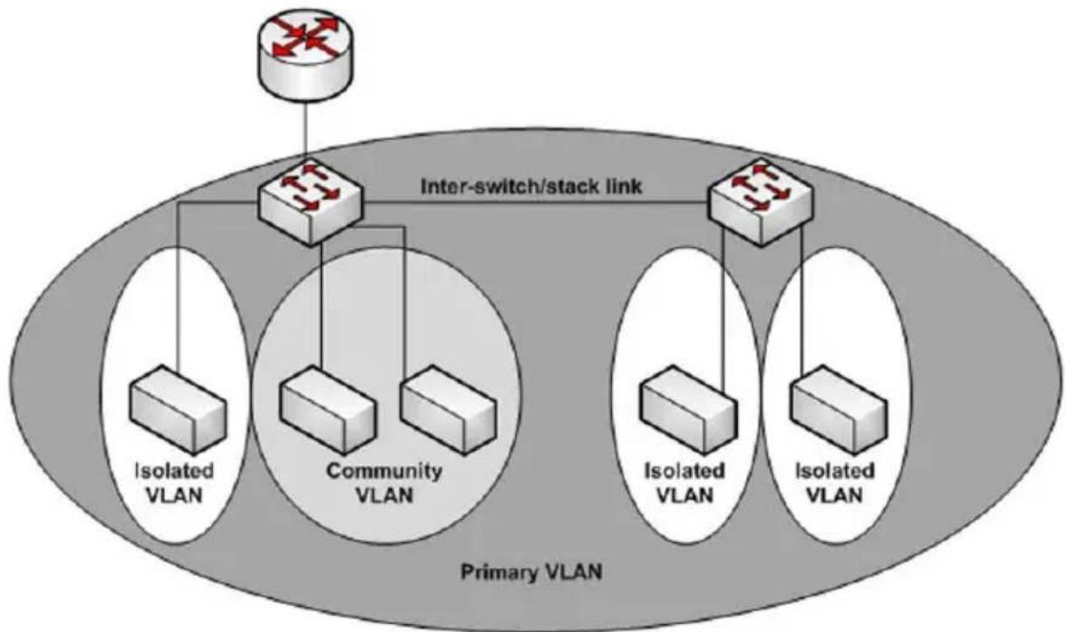
flowchart
graph TD
    A["Router"] --> B["Inter-switch/stack link"]
    B --> C["Isolated VLAN"]
    B --> D["Community VLAN"]
    B --> E["Isolated VLAN"]
    B --> F["Isolated VLAN"]
    style A fill:#f9f,stroke:#333
    style B fill:#ccf,stroke:#333
    style C fill:#cfc,stroke:#333
    style D fill:#cfc,stroke:#333
    style E fill:#cfc,stroke:#333
    style F fill:#cfc,stroke:#333
Isolated VLAN
An endpoint connected over an isolated VLAN is allowed to communicate with endpoints connected to promiscuous ports only. Endpoints connected to adjacent endpoints over an isolated VLAN cannot communicate with each other.
Community VLAN
An endpoint connected over a community VLAN is allowed to communicate with the endpoints within the community and can also communicate with any configured promiscuous port. The endpoints which belong to one community cannot communicate with endpoints which belong to a different community or with endpoints connected over isolated VLANs.
Private VLANs Operation in the Switch Environment
The Private VLAN feature operates in a stacked or single switch environment. The stack links are transparent to the configured VLAN, thus there is no need for special private VLAN configuration. Any private VLAN port can reside on any stack member.
In order to enable Private VLAN operation across multiple switches which are not stacked, the inter-switch links should carry VLANs which belong to a private VLAN. The trunk ports which connect neighbor switches have to be assigned to the primary, isolated, and community VLANs of a private VLAN.
In regular VLANs, ports in the same VLAN switch traffic at L2. However for private VLAN, the promiscuous port is in the primary VLAN whereas the isolated or community ports are in the secondary VLAN. Similarly, for broadcasts, in regular VLANs, ports in the same VLAN receive broadcast traffic. However, for private VLANs, the ports to which the broadcast traffic is forwarded depend on the type port on which the traffic was received. If the received port is a host port; the traffic is forwarded to all promiscuous and trunk ports. If the received port is community port the broadcast traffic is forwarded to promiscuous, trunk and community ports in the same VLAN. A promiscuous port sends traffic to other promiscuous ports, isolated and community ports.
Commands in this Chapter
This chapter explains the following commands:
| dvlan-tunnel ethertype | show dvlan-tunnel | switchport general acceptable-frame-type tagged-only | vlan association subnet |
| console(config-if-vlan10)# | show dvlan-tunnel interface | switchport general allowed vlan | vlan database |
| interface vlan show interfaces switchport | switchport general ingress-filtering disable | vlan makestatic | |
| interface range vlan show port protocol | switchport general pvid | vlan protocol group | |
| mode dvlan-tunnel show vlan switchport | mode vlan protocol group add protocol | ||
| name (VLAN Configuration) | show vlan association mac | switchport trunk vlan protocol group name | |
| protocol group show vlan association subnet | vlan vlan protocol group remove | ||
| protocol vlan group | switchport accessvlan | vlan (Global Config) | show vlan private-vlan – |
| protocol vlan group all | switchport general forbidden vlan | vlan association mac | – |
| Private VLAN Commands | |||
| switchport private-vlan | private-vlan show interfaces switchport | show vlan private-vlan | |
| switchport mode private-vlan | – | – | – |
dvlan-tunnel ethertype
Use the dvlan-tunnel ethertype command in Global Configuration mode to enable the configuration of the inner and outer VLAN tag ethertype.
To configure the EtherType to its default value, use the no form of this command.
Syntax
dvlan-tunnel ethertype {802.1Q | vman | custom 0-65535 [primary-tpid]} no dvlan-tunnel ethertype
Parameter Description
| Parameter Description | |
| 802.1Q Configures the EtherType as 0x8100. | |
| vman Configures the EtherType as 0x88A8 | |
| custom Configures a custom EtherType for the DVLAN tunnel. The value must be 0-65535. | |
| primary-tpid Globally configures the tag protocol identifier on the outer VLAN tag (S-TAG). If this parameter is not given, the inner vlan (C-TAG) is configured. | |
Default Configuration
The default for this command is 802.1Q. The default S-TAG TPID, when double-tagging is enabled, is 0x88A8. The default C-TAG TPID when double vlan tagging is enabled is 0x8100.
Command Mode
Global Configuration, Interface Configuration mode
User Guidelines
This command configures the TPID value on the outer VLAN (S-VLAN). The global configuration form of the command configures all physical and port-channel interfaces on which double VLAN tunneling is enabled to use the specified ethertype. The interface form of the command enables/disables the use of the ethertype on the specific interface. The ethertype used in the interface form of the command must use the same ethertype as specified in the global configuration form of the command. The inner vlan tag (C-TAG) is configured using the switchport command in interface configuration mode.
Example
The following example displays configuring Double VLAN tunnel for vman EtherType.
console(config)#dvlan-tunnel ethertype vman
interface vlan
The vlan routing command is deprecated in favor of the interface vlan command. Use the interface vlan command in Global Configuration mode to enter VLAN Interface Configuration mode.
Syntax
interface vlan {vlan-id} [nsf-index]
Parameter Description
| Parameter Description | |
| vlan-id The ID of a valid VLAN (Range 1–4093). | |
Default Configuration
By default, routing is enabled on VLAN 1. However, VLAN 1 does not route packets until an IP address is assigned to the VLAN. DHCP is not enabled on VLAN 1 by default.
Command Mode
VLAN Configuration or Global Configuration modes
User Guidelines
Assigning an IP address to a VLAN interface enables routing on the VLAN interface.
Examples
console(config-vlan10)# interface vlan 10 console(config-if-vlan10)#
interface range vlan
Use the interface range vlan command in Global Configuration mode to execute a command on multiple VLANs at the same time.
Syntax
interface range vlan { vlan-range | all}
- vlan-range — A list of valid VLAN IDs to add. Separate nonconsecutive VLAN IDs with a comma and no spaces; use a hyphen to designate a range of IDs. (Range: 2–4093)
• all — All existing static VLANs.
Default Configuration
This command has no default configuration.
Command Mode
Global Configuration mode
User Guidelines
Commands used in the interface range context are executed independently on each interface in the range. If the command returns an error on one of the interfaces, an error message is displayed and execution continues on other interfaces.
Example
The following example groups VLAN 221 through 228 and VLAN 889 to execute the commands entered in interface range mode.
console(config)#interface range vlan 221-228,889
console(config-if)#
mode dvlan-tunnel
Use the mode dvlan-tunnel command in Interface Configuration mode to enable Double VLAN Tunneling on the specified interface. To disable Double VLAN Tunneling on the specified interface, use the no form of this command.
Syntax
mode dvlan-tunnel
no mode dvlan-tunnel
Default Configuration
By default, Double VLAN Tunneling is disabled.
Command Mode
Interface Configuration (gigabitethernet, port-channel, tengigabitethernet) mode
User Guidelines
Use the global configuration command dvlan-tunnel ethertype to configure the inner and outer TPIDs. When dvlan-tunnel is enabled on an interface, the interface is configured as an uplink or service provider (SP) port. All other interfaces on the switch behave like access (customer) ports.
Uplink Port Behavior
If a single-tagged (SP tagged) or double-tagged (SP tag as outer tag) packet ingresses an uplink port, the switch passes it through unchanged to the respective access or uplink ports.
If an untagged or single tagged (802.1Q tagged) packet ingresses an uplink port, the switch tags it with the configured ethertype and service provider VLAN ID taken from the ingress port PVID.
Access Port Behavior
Ingress packets on an access port are always tagged by the switch. Packets are tagged on ingress with the configured ethertype and the service provider ID taken from the PVID. On egress, the access port strips all (SP) tags belonging to service provider VLANS.
Example
The following example displays how to enable Double VLAN Tunneling at gigabit ethernet port 1/0/1.
console(config-if-1/0/1)#mode dvlan-tunnel
name (VLAN Configuration)
Use the name command in VLAN Configuration mode to configure the VLAN name. To return to the default configuration, use the no form of this command.

NOTE: This command cannot be configured for a range of interfaces (range context).
Syntax
name vlan-name
no name
Parameter Description
| Parameter Description | |
| vlan-name The name of the VLAN. Must be 1–32 characters in length. | |
Default Configuration
The default VLAN name is default.
Command Mode
VLAN Configuration mode
User Guidelines
The VLAN name may include any alphanumeric characters including a space, underscore, or dash. Enclose the string in double quotes to include spaces within the name. The surrounding quotes are not used as part of the name. The CLI does not filter illegal characters and may truncate entries at the first illegal character or reject the entry entirely. The name of VLAN 1 cannot be changed.
Example
The following example configures a VLAN name of office2 for VLAN 2.
console(config)#vlan 2
console(config-vlan2)#name "RDU-NOC Management VLAN"
protocol group
Use the protocol group command in VLAN Configuration mode to attach a VLAN ID to the protocol-based group identified by groupid. A group may only be associated with one VLAN at a time. However, the VLAN association can be changed. The referenced VLAN should be created prior to the creation of the protocol-based group except when GVRP is expected to create the VLAN.
To detach the VLAN from this protocol-based group identified by this groupid, use the no form of this command.
Syntax
protocol group groupid vlanid
no protocol group groupid vlanid
- groupid — The protocol-based VLAN group ID, which is automatically generated when you create a protocol-based VLAN group with the vlan protocol group command. To see the group ID associated with the name of a protocol group, use the show port protocol all command.
• vlanid—A valid VLAN ID.
Default Configuration
This command has no default configuration.
Command Mode
VLAN Configuration mode
User Guidelines
This command has no user guidelines.
Example
The following example displays how to attach the VLAN ID "100" to the protocol-based VLAN group "3."
console#vlan database console(config-vlan)#protocol group 3 100
protocol vlan group
Use the protocol vlan group command in Interface Configuration mode to add the physical unit/slot/port interface to the protocol-based group identified by groupid. A group may have more than one interface associated with it. Each interface and protocol combination can be associated with one group only. If adding an interface to a group causes any conflicts with protocols currently associated with the group, this command fails and the interface(s) are not added to the group. Ensure that the referenced VLAN is created prior to the creation of the protocol-based group except when GVRP is expected to create the VLAN.
To remove the interface from this protocol-based VLAN group that is identified by this groupid, use the no form of this command.
If you select all, all ports are removed from this protocol group.
Syntax
protocol vlan group groupid
no protocol vlan group groupid
- groupid — The protocol-based VLAN group ID, which is automatically generated when you create a protocol-based VLAN group with the vlan protocol group command. To see the group ID associated with the name of a protocol group, use the show port protocol all command.
Default Configuration
This command has no default configuration.
Command Mode
Interface Configuration (Ethernet) mode
User Guidelines
This command has no user guidelines.
Example
The following example displays how to add a physical port interface to the group ID of "2."
console(config-if-1/0/1)#protocol vlan group 2
protocol vlan group all
Use the protocol vlan group all command in Global Configuration mode to add all physical interfaces to the protocol-based group identified by groupid. A group may have more than one interface associated with it. Each interface and protocol combination can be associated with one group only. If adding an interface to a group causes any conflicts with protocols currently associated with the group, this command fails and the interface(s) are not added to the group. Ensure that the referenced VLAN is created prior to the creation of the protocol-based group except when GVRP is expected to create the VLAN.
To remove all interfaces from this protocol-based group that is identified by this groupid, use the no form of the command
Syntax
protocol vlan group all groupid
no protocol vlan group all groupid
- groupid — The protocol-based VLAN group ID, which is automatically generated when you create a protocol-based VLAN group with the vlan protocol group command. To see the group ID associated with the name of a protocol group, use the show port protocol all command.
Default Configuration
This command has no default configuration.
Command Mode
Global Configuration mode
User Guidelines
This command has no user guidelines.
Example
The following example displays how to add all physical interfaces to the protocol-based group identified by group ID "2."
console(config)#protocol vlan group all 2
show dvlan-tunnel
Use the show dvlan-tunnel command in Privileged EXEC mode to display all interfaces enabled for Double VLAN Tunneling.
Syntax
show dvlan-tunnel
Default Configuration
This command has no default configuration.
Command Mode
Privileged EXEC mode, Config mode and all Config sub-modes
User Guidelines
This command has no user guidelines.
Example
The following example shows how to display all interfaces for Double VLAN Tunneling.
console#show dvlan-tunnel
Interfaces Enabled for DVLAN Tunneling..... 1/0/1
show dvlan-tunnel interface
Use the show dvlan-tunnel interface command in Privileged EXEC mode to display detailed information about Double VLAN Tunneling for the specified interface or all interfaces.
Syntax
show dvlan-tunnel interface {gigabithethernet unit/slot/port | tengigabitethernet unit/slot/port | all}
• all — Displays information for all interfaces.
Default Configuration
This command has no default configuration.
Command Mode
Privileged EXEC mode, Config mode and all Config sub-modes
User Guidelines
This command has no user guidelines.
Example
The following example displays detailed information for port 1/0/1.
console#show dvlan-tunnel interface 1/0/1
Interface Mode EtherType
1/0/1 Enable vMAN
The following table describes the significant fields shown in the example.
| Field Description | |
| Mode This field s | specifies the administrative mode through which Double VLAN Tunneling can be enabled or disabled. The default value for this field isdisabled. |
| Interface Interface Number. | |
| EtherType This fi | ield represents a 2-byte hex EtherType to be used as the first 16 bits of the DVLAN tunnel. The three different EtherType tags are: (1) 802.1Q, which represents the commonly used value of 0x8100. (2) vMAN, which represents the commonly used value of 0x88A8. (3) If EtherType is not one of these two values, it is a custom tunnel value, representing any value in the range of 0 to 65535. |
show interfaces switchport
Use the show interfaces switchport command in Privileged EXEC mode to display switchport configuration, including the private VLAN mappings.
Syntax
show interfaces switchport {{gigabitethernet unit/slot/port | port-channel port-channel-number | tengigabitethernet unit/slot/port}}
Parameter Description
The command displays the following information.
| Parameter Description | |
| private-vlan host-association | Displays VLAN association for the private-VLAN host ports. |
| private-vlan mapping | Displays VLAN mapping for the private-VLAN promiscuous ports. |
Default Configuration
This command has no default configuration.
Command Mode
Privileged EXEC mode, Interface Config mode and all Config sub-modes
User Guidelines
Do not configure private VLANs on ports configured with any of these features:
- Link Aggregation Control Protocol (LACP)
• Multicast VLAN Registration (MVR) - Voice VLAN
It is recommended that the private VLAN host ports be configured as spanning-tree portfast.
Examples
The following example displays switchport configuration individually for gi1/0/1.
console#show interface switchport gigabitethernet 1/0/1
Port 1/0/1:
VLAN Membership mode: General
Operating parameters:
PVID: 1 (default)
Ingress Filtering: Enabled
Acceptable Frame Type: All
GVRP status: Enabled
Protected: Enabled
Port 1/0/1 is member in:
VLAN Name Egress rule Type
1 default untagged Default
8 VLAN008 tagged Dynamic
11 VLAN0011 tagged Static
19 IPv6 VLAN untagged Static
72 VLAN0072 untagged Static
Static configuration:
PVID: 1 (default)
Ingress Filtering: Enabled
Acceptable Frame Type: All
Port 1/0/1 is statically configured to:
VLAN Name Egress rule
11 VLAN0011 tagged
19 IPv6 VLAN untagged
72 VLAN0072 untagged
Forbidden VLANS:
VLAN Name
73 Out
The following example displays switchport configuration individually for 1/0/2.
console#show interface switchport gigabitethernet 1/0/2
Port 1/0/2:
VLAN Membership mode: General
Operating parameters:
PVID: 4095 (discard vlan)
Ingress Filtering: Enabled
Acceptable Frame Type: All
Port 1/0/1 is member in:
VLAN Name Egress rule Type
91 IP Telephony tagged Static
Static configuration:
PVID: 8
Ingress Filtering: Disabled
Acceptable Frame Type: All
Port 1/0/2 is statically configured to:
VLAN Name Egress rule
8 VLAN0072 untagged
91 IP Telephony tagged
Forbidden VLANS:
VLAN Name
73 Out
The following example displays switchport configuration individually for 2/0/19.
console#show interfaces switchport gigabitethernet 2/0/19
Port 2/0/19:
Operating parameters:
PVID: 2922
Ingress Filtering: Enabled
Acceptable Frame Type: Untagged
GVRP status: Disabled
Port 2/0/19 is member in:
VLAN Name Egress rule Type
2921 Primary A untagged Static
2922 Community A1 untagged Static
Static configuration:
PVID: 2922
Ingress Filtering: Enabled
Acceptable Frame Type: Untagged
GVRP status: Disabled
Port 2/0/19 is member in:
VLAN Name Egress rule Type
2921 Primary A untagged Static
2922 Community A1 untagged Static
show port protocol
Use the show port protocol command in Privileged EXEC mode to display the Protocol-Based VLAN information for either the entire system or for the indicated group.
Syntax
show port protocol {groupid | all}
- groupid — The protocol-based VLAN group ID, which is automatically generated when you create a protocol-based VLAN group with the vlan protocol group command.
• all — Enter all to show all interfaces.
Default Configuration
This command has no default configuration.
Command Mode
Privileged EXEC mode, Config mode and all Config sub-modes
User Guidelines
This command has no user guidelines.
Example
The following example displays the Protocol-Based VLAN information for either the entire system.
console#show port protocol all
Group
Group
Name ID Protocol(s VLAN Interface(s))
test 1 IP 1 1/0/1
show vlan
Use the show vlan command in Privileged EXEC mode to display detailed information, including interface information and dynamic VLAN type, for a specific VLAN. The ID is a valid VLAN identification number.
Syntax
show vlan [id vlanid /name vlan-name]
Parameter Description
| Parameter Description | |
| vlanid VLAN identifier | r |
| vlan-name A valid VLAN name (Range 1-32 characters) | |
Default Configuration
This command has no default configuration.
Command Mode
Privileged EXEC mode, Config mode and all Config sub-modes
User Guidelines
This command has no user guidelines.
Example
The following example displays information for VLAN id 1, 2 and 3.
console#show vlan id 1
| VLAN | Name | Ports | Type |
| 1 | default | Po1-48,Gi1/0/1-10 | Default |
console#show vlan id 2
| VLAN | Name | Ports | Type |
| 2 | VLAN0002 | Gi1/0/11-20 | Dynamic (DOT1X) |
console#show vlan id 3
| VLAN | Name | Ports | Type |
| 3 | VLAN0003 | Gi1/0/21-24 | Dynamic (GVRP) |
show vlan association mac
Use the show vlan association mac command in Privileged EXEC mode to display the VLAN associated with a specific configured MAC address. If no MAC address is specified, the VLAN associations of all the configured MAC addresses are displayed.
Syntax
show vlan association mac [mac-address]
- mac-address — Specifies the MAC address to be entered in the list. (Range: Any valid MAC address)
Default Configuration
This command has no default configuration.
Command Mode
Privileged EXEC mode, Config mode and all Config sub-modes
User Guidelines
This command has no user guidelines.
Example
The following example shows no entry in MAC address to VLAN cross-reference.
console#show vlan association mac
MAC Address VLAN ID
0001.0001.0001.0001 1
console#
show vlan association subnet
Use the show vlan association subnet command in Privileged EXEC mode to display the VLAN associated with a specific configured IP-Address and netmask. If no IP Address and net mask are specified, the VLAN associations of all the configured IP-subnets are displayed.
Syntax
show vlan association subnet [ip-address ip-mask]
- ip-address — Specifies IP address to be shown
- ip-mask — Specifies IP mask to be shown
Default Configuration
This command has no default configuration.
Command Mode
Privileged EXEC mode, Config mode and all Config sub-modes
User Guidelines
The command has no user guidelines.
Example
The following example shows the case if no IP Subnet to VLAN association exists.
console#show vlan association subnet
IP Address IP Mask VLAN ID
The IP Subnet to VLAN association does not exist.
switchport access vlan
Use the switchport access vlan command in Interface Configuration mode to configure the VLAN ID when the interface is in access mode. To reconfigure the default, use the no form of this command.
Syntax
switchport access vlan vlan-id
no switchport access vlan
- vlan-id — A valid VLAN ID of the VLAN to which the port is configured.
Default Configuration
The default value for the vlan-id parameter is 1.
Command Mode
Interface Configuration (gigabitethernet, port-channel, tengigabitethernet) mode
User Guidelines
This command removes the port from the previous VLAN membership and adds it to the specified VLAN. The no form of the command sets the port VLAN membership to VLAN 1.
Example
The following example configures interface gi1/0/8 to operate in access mode with a VLAN membership of 23. Received untagged packets are processed on VLAN 23. Received packets tagged with VLAN 23 are also accepted. Other received tagged packets are discarded.
console(config)#interface gigabitethernet 1/0/8
console(config-if-1/0/8)#switchport access vlan 23
switchport general forbidden vlan
Use the switchport general forbidden vlan command in Interface Configuration mode to forbid adding specific VLANs to a general mode port. To revert to allowing the addition of specific VLANs to the port, use the remove parameter of this command.
Syntax
switchport general forbidden vlan {add vlan-list | remove vlan-list}
- add vlan-list — List of valid VLAN IDs to add to the forbidden list.
Separate nonconsecutive VLAN IDs with a comma and no spaces. Use a hyphen to designate a range of IDs. - remove vlan-list — List of valid VLAN IDs to remove from the forbidden list. Separate nonconsecutive VLAN IDs with a comma and no spaces. Use a hyphen to designate a range of IDs.
Default Configuration
All VLANs allowed.
Command Mode
Interface Configuration (gigabitethernet, port-channel, tengigabitethernet) mode
User Guidelines
This configuration only applies to ports configured in general mode.
Example
The following example forbids adding VLAN numbers 234 through 256 to port 1/0/8.
console(config)#interface gigabitethernet 1/0/8
console(config-if-1/0/8)#switchport general forbidden vlan add 234-256
switchport general acceptable-frame-type tagged-only
Use the switchport general acceptable-frame-type tagged-only command in Interface Configuration mode to discard untagged frames at ingress. To enable untagged frames at ingress, use the no form of this command.
Syntax
switchport general acceptable-frame-type tagged-only no switchport general acceptable-frame-type tagged-only
Default Configuration
All frame types are accepted at ingress.
Command Mode
Interface Configuration (gigabitethernet, port-channel, tengigabitethernet) mode
User Guidelines
This command has no user guidelines.
Example
The following example configures 1/0/8 to discard untagged frames at ingress.
console(config)#interface gigabitethernet 1/0/8
console(config-if-1/0/8)#switchport general
acceptable-frame-type tagged-only
switchport general allowed vlan
Use the switchport general allowed vlan command in Interface
Configuration mode to add VLANs to or remove VLANs from a general port.
Syntax
switchport general allowed vlan add vlan-list [tagged | untagged]
switchport general allowed vlan remove vlan-list
- add vlan-list — List of VLAN IDs to add. Separate nonconsecutive VLAN IDs with a comma and no spaces. Use a hyphen to designate a range of IDs.
- remove vlan-list—List of VLAN IDs to remove. Separate nonconsecutive VLAN IDs with a comma and no spaces. Use a hyphen to designate a range of IDs.
- tagged — Sets the port to transmit tagged packets for the VLANs. If the port is added to a VLAN without specifying tagged or untagged, the default is untagged.
- untagged — Sets the port to transmit untagged packets for the VLANs.
Default Configuration
Untagged.
Command Mode
Interface Configuration (gigabitethernet, port-channel, tengigabitethernet) mode
User Guidelines
You can use this command to change the egress rule (for example, from tagged to untagged) without first removing the VLAN from the list.
Example
The following example shows how to add VLANs 1, 2, 5, and 8 to the allowed list.
console(config-if-1/0/8)#switchport general allowed vlan add 1,2,5,8 tagged
switchport general ingress-filtering disable
Use the switchport general ingress-filtering disable command in Interface Configuration mode to disable port ingress filtering. To enable ingress filtering on a port, use the no form of this command.
Syntax
switchport general ingress-filtering disableno switchport general ingress-filtering disable
Default Configuration
Ingress filtering is enabled.
Command Mode
Interface Configuration (gigabitethernet, port-channel, tengigabitethernet) mode
User Guidelines
This command has no user guidelines.
Example
The following example shows how to enables port ingress filtering on 1/0/8.
console(config)#interface gigabitethernet 1/0/8 console(config-if-1/0/8)#switchport general ingress-filtering disable
switchport general pvid
Use the switchport general pvid command in Interface Configuration mode to configure the Port VLAN ID (PVID) when the interface is in general mode. Use the switchport mode general command to set the VLAN membership mode of a port to "general." To configure the default value, use the no form of this command.
Syntax
switchport general pvid vlan-id
no switchport general pvid
- vlan-id—PVID. The VLAN ID may belong to a non-existent VLAN.
Default Configuration
The default value for the vlan-id parameter is 1 when the VLAN is enabled. Otherwise, the value is 4093.
Command Mode
Interface Configuration (gigabitethernet, port-channel, tengigabitethernet) mode
User Guidelines
Setting a new PVID does NOT remove the previously configured PVID VLAN from the port membership.
Example
The following example shows how to configure the PVID for 1/0/8, when the interface is in general mode.
console(config)#interface gigabitethernet 1/0/8
console(config-if-1/0/8)#switchport general pvid 234
switchport mode
Use the switchport mode command in Interface Configuration mode to configure the VLAN membership mode of a port. To reset the mode to the appropriate default for the switch, use the no form of this command.
Syntax
switchport mode {access | trunk | general}
no switchport mode
Parameter Description
| Parameter Description | |
| access An access port | connects to a single end station belonging to a single VLAN. An access port is configured with ingress filtering enabled and will accept either an untagged frame or a packet tagged with the access port VLAN. Tagged packets received with a VLAN other than the access port VLAN are discarded. An access port transmits only untagged packets. |
| trunk | A trunk port connects two switches. A trunk port may belong to multiple VLANs. A trunk port accepts only packets tagged with the VLAN IDs of the VLANs to which the trunk is a member or untagged packets if configured with a native VLAN. A trunk port only transmits tagged packets for member VLANs other than the native VLAN and untagged packets for the native VLAN. |
| general Full 802.1q support VLAN interface. A general mode port is a combination of both trunk and access ports capabilities. It is possible to fully configure all VLAN features on a general mode port. Both tagged and untagged packets may be accepted and transmitted. | |
Default Configuration
The default switchport mode is access.
Command Mode
Interface Configuration (gigabitethernet, port-channel, tengigabitethernet) mode
User Guidelines
This command has no user guidelines.
Example
The following example configures 1/0/5 to access mode.
console(config)#interface gigabitethernet 1/0/5
console(config-if-1/0/5)#switchport mode access
switchport trunk
Use the switchport trunk command in Interface Configuration mode to add VLANs to or remove VLANs from a trunk port, or to set the native VLAN for an interface in Trunk Mode.
Syntax
switchport trunk {allowed vlan vlan-list | native vlan vlan-id}
no switchport trunk allowed vlan
Parameter Description
| Parameter Description | |
| vlan-list Set the list of allowed VLANs that can receive and send traffic on this interface in tagged format when in trunking mode. The default is all. The vlan-list format is as follows:The vlan-list format is all | [add | remove | except] vlan-atom [, v l a n - a t o m . . . ] where:all specifies all VLANs from 1 to 4093. This keyword is not allowed on commands that do not permit all VLANs in the list to be set at the same time.add adds the defined list of VLANs to those currently set instead of replacing the list.remove removes the defined list of VLANs from those currently set instead of replacing the list. Valid IDs are from 1 to 4093; extended-range VLAN IDs of the form X-Y or X,Y,Z are valid in this command.except lists the VLANs that should be calculated by inverting the defined list of VLANs. (VLANs are added except the ones specified.)vlan-atom is either a single VLAN number from 1 to 4093 or a continuous range of VLANs described by two VLAN numbers, the lesser one first, separated by a hyphen. | |
| valid-id A valid VLAN id from 1–4093. | |
Default Configuration
All VLANs are members of a trunk port.
VLAN 1 is the native VLAN on a trunk port. VLAN 1 is the default VLAN for access mode ports.
Command Mode
Interface Configuration (gigabitethernet, port-channel, tengigabitethernet) mode
User Guidelines
Untagged traffic received on a trunk port is forwarded on the native VLAN, if configured.
To drop untagged traffic on a trunk port, remove the native VLAN from the trunk port. (Ex. switchport trunk allowed vlan remove 1.) Management traffic is still allowed on the trunk port in this configuration.
The no form of the command sets the trunk port back to the defaults.
It is possible to exclude VLANs that have not yet been created from trunk port membership.
Example
console(config-if-Gi1/0/1)#switchport trunk allowed vlan 1-1024 console(config-if-Gi1/0/1)#switchport trunk allowed vlan except 1,2,3,5,7,11,13
vlan
Use the vlan command in VLAN Database mode to configure a VLAN. To delete a VLAN, use the no form of this command.
Syntax
vlan vlan-range
no vlan vlan-range
- vlan-range — A list of valid VLAN IDs to be added. List separate, non-consecutive VLAN IDs separated by commas (without spaces); use a hyphen to designate a range of IDs. (Range: 2–4093)
Default Configuration
This command has no default configuration.
Command Mode
VLAN Database mode
User Guidelines
Deleting the VLAN used by an access port will cause that port to become unusable until it is assigned a VLAN that exists. Creating a VLAN adds it to the allowed list for all trunk ports except for those where it is specifically excluded.
Example
The following example shows how to create (add) VLAN of IDs 22, 23, and 56.
console(config-vlan)#vlan 22,23,56
console(config-vlan)#
vlan (Global Config)
Use the vlan command in Global Configuration mode to configure a VLAN. To delete a VLAN, use the no form of this command.
Syntax
vlan {vlan-id | vlan-range}
no vlan {vlan-id | vlan-range}
Parameter Description
| Parameter Description | |
| vlan-id | A valid VLAN ID. (Range: 1-4093) |
| vlan-range | A list of valid VLAN IDs. List separate, non-consecutive VLAN IDs separated by commas (without spaces). Use a hyphen to designate a range of IDs. (Range: 1-4093) |
Default Configuration
This command has no default configuration.
Command Mode
Global Configuration (Config)
User Guidelines
Deleting the VLAN for an access port will cause that port to become unusable until it is assigned a VLAN that exists. Creating a VLAN adds it to the allowed list for all trunk ports except those where it is specifically excluded.
Example
The following example shows how to create (add) VLAN of IDs 22, 23, and 56.
console(config)#vlan 22,23,56
console(config-vlan)#
vlan association mac
Use the vlan association mac command in VLAN Config mode to associate a MAC address to a VLAN. The maximum number of MAC-based VLANs is 256. Only packets with a matching source IP address are placed in the VLAN.
Syntax
vlan association mac mac-address
no vlan association mac mac-address
mac-address—MAC address to associate to the VLAN. (Range: Any MAC address in the format xxxx.xxxx.xxxx or xx:xx:xx:xx:xx:xx)
Default Configuration
No assigned MAC address.
Command Mode
VLAN Config mode
User Guidelines
This command has no user guidelines.
Example
The following example associates MAC address with VLAN ID 1.
console(config)# vlan 1
console(config-vlan-1)#vlan association mac 0001.0001.0001
vlan association subnet
Use the vlan association subnet command in VLAN Config mode to associate a VLAN to a specific IP-subnet. Only packets with a matching source IP address are placed into the VLAN.
Syntax
vlan association subnet ip-address subnet-mask
no vlan association subnet ip-address subnet-mask
- ip-address — Source IP address. (Range: Any valid IP address)
- subnet-mask — Subnet mask. (Range: Any valid subnet mask)
Default Configuration
No assigned ip-subnet.
Command Mode
VLAN Config mode
User Guidelines
This command has no user guidelines.
Example
The following example associates the 192.168.0.xxx IP address with VLAN ID 1.
console(config)# vlan 1
console(config-vlan-1)#vlan association subnet 192.168.0.0 255.255.255.0
vlan database
Use the vlan database command in Global Configuration mode to enter the VLAN database configuration mode.
Syntax
vlan database
Default Configuration
This command has no default configuration.
Command Mode
Global Configuration mode
User Guidelines
This command has no user guidelines.
Example
The following example enters the VLAN database mode.
console(config)#vlan database
console(config-vlan)#
vlan makestatic
This command changes a dynamically created VLAN (one that is created by GVRP registration) to a static VLAN (one that is permanently configured and defined). The ID is a valid VLAN identification number. VLAN range is 2-4093.
Syntax
vlan makestatic vlan-id
• vlan-id—Valid vlan ID. Range is 2–4093.
Default Configuration
This command has no default configuration.
Command Mode
VLAN Database Mode
User Guidelines
The dynamic VLAN (created via GRVP) should exist prior to executing this command. See the Type column in output from the show vlan command to determine that the VLAN is dynamic.
Example
The following changes vlan 3 to a static VLAN.
console(config-vlan)#vlan makestatic 3
vlan protocol group
Use the vlan protocol group command in Global Configuration mode to add protocol-based groups to the system. When a protocol group is created, it is assigned a unique group ID number. The group ID is used to identify the group in subsequent commands. Use the no form of the command to remove the specified VLAN protocol group name from the system.
Syntax
vlan protocol group groupid
no vlan protocol group groupid
- groupid — The protocol-based VLAN group ID, to create a protocol-based VLAN group. To see the created protocol groups, use the show port protocol all command.
Default Configuration
This command has no default configuration.
Command Mode
Global Configuration mode
User Guidelines
This command has no user guidelines.
Example
console(config)# vlan protocol group 1
vlan protocol group add protocol
Use the vlan protocol group add protocol command in Global Configuration mode to add a protocol to the protocol-based VLAN groups identified by groupid. A group may have more than one protocol associated with it. Each interface and protocol combination can be associated with one group only. If adding a protocol to a group causes any conflicts with interfaces currently associated with the group, this command fails and the protocol is not added to the group.
To remove the protocol from the protocol-based VLAN group identified by groupid, use the no form of this command.
Syntax
vlan protocol group add protocol groupid ethertype value
no vlan protocol group add protocol groupid ethertype value
- groupid — The protocol-based VLAN group ID, which is automatically generated when you create a protocol-based VLAN group with the vlan protocol group command. To see the group ID associated with the name of a protocol group, use the show port protocol all command.
- ethertype value — The protocol you want to add. The ethertype value can be any valid hexadecimal number in the range 0x0600 to 0xffff.
Default Configuration
This command has no default configuration.
Command Mode
Global Configuration mode
User Guidelines
This command has no user guidelines.
Example
The following example displays how to add the "ip" protocol to the protocol based VLAN group identified as "2."
console(config)#vlan protocol group add protocol 2 ethertype 0xXXXX
vlan protocol group name
This is a new command for assigning a group name to vlan protocol group id.
Syntax
vlan protocol group name groupid groupName
no vlan protocol group name groupid
- groupid—The protocol-based VLAN group ID, which is automatically generated when you create a protocol-based VLAN group with the vlan protocol group command. To see the group ID associated with the name of a protocol group, use the show port protocol all command
- groupName—The group name you want to add. The group name can be up to 16 characters length. It can be any valid alpha numeric characters.
Default Configuration
This command has no default configuration.
Command Mode
Global Configuration mode
User Guidelines
This command has no user guidelines.
Example
console(config)# vlan protocol group name 1 usergroup
vlan protocol group remove
Use the vlan protocol group remove command in Global Configuration mode to remove the protocol-based VLAN group identified by groupid.
Syntax
vlan protocol group remove groupid
- groupid — The protocol-based VLAN group ID, which is automatically generated when you create a protocol-based VLAN group with the vlan protocol group command. To see the group ID associated with the name of a protocol group, use the show port protocol all command.
Default Configuration
This command has no default configuration.
Command Mode
Global Configuration mode
User Guidelines
This command has no user guidelines.
Example
The following example displays the removal of the protocol-based VLAN group identified as "2."
console(config)#vlan protocol group remove 2
switchport private-vlan
Use the switchport private-vlan command in Interface Config mode to define a private VLAN association for an isolated or community port or a mapping for a promiscuous port.
Use the no form of the command to remove the private VLAN association or mapping from the interface.
Syntax
switchport private-vlan {host-association primary-vlan-id secondary-vlan-id | mapping primary-vlan-id [add|remove] secondary-vlan-list}
no switchport private-vlan {host-association | mapping}
Parameter Description
| Parameter Description | |
| host-association Defines VLAN associations for community or host ports. | |
| mapping Defines the | private VLAN mapping for promiscuous ports. |
| primary-vlan-id Primary VLAN ID of a private VLAN. | |
| secondary-vlan-id Secondary (isolated or community) VLAN ID of a private VLAN. | |
| add Associates the secondary VLAN with the primary one. | |
| remove Deletes the secondary VLANs from the primary VLAN association. | |
| secondary-vlan-list A list of secondary VLANs to be mapped to a primary VLAN. | |
Default Configuration
This command has no default association or mapping configuration.
Command Mode
Interface Configuration (physical or port-channel)
User Guidelines
This command has no user guidelines.
switchport mode private-vlan
Use the switchport mode private-vlan command in Interface Config mode to define a private VLAN association for an isolated or community interface or a mapping for a promiscuous interface.
Use the no form of the command to remove the private VLAN association or mapping from the interface.
Syntax
switchport mode private-vlan {host|promiscuous}
no switchport mode
Parameter Description
| Parameter Description | |
| host-association Configure | figure the interface as a private VLAN host port. I Host ports are community or isolated ports, depending on the VLAN to which they belong. |
| promiscuous Configure | ure the interface as a private VLAN promiscuous port.Promiscuous ports are members of the primary VLAN. |
Default Configuration
This command has no default configuration. By default, a port is neither configured as promiscuous or host.
Command Mode
Interface Configuration (physical or port-channel)
User Guidelines
Do not configure private VLANs on ports configured with any of these features:
- Link Aggregation Control Protocol (LACP)
• Multicast VLAN Registration (MVR) - Voice VLAN
It is recommended that the private VLAN host ports be configured as spanning-tree portfast.
private-vlan
Use the private-vlan command in VLAN Config mode to define a private VLAN association between the primary and secondary VLANs.
Use the no form of the command to remove the private VLAN association.
Syntax
private-vlan {primary|isolated|community|association [add|remove]
no private-vlan [association]
Parameter Description
The command displays the following information:
| Parameter Description | |
| association Defines an association between the primary VLAN and secondary VLANs. | |
| primary Specify that the selected VLAN is the primary VLAN. | |
| community Specify that the selected VLAN is the community VLAN. | |
| isolated Specify that the selected VLAN is the isolated VLAN. | |
| add Associates a secondary VLAN with the primary VLAN. | |
| remove Deletes the secondary VLAN association with the primary VLAN. | |
| vlan-list A list of secondary VLAN ids to be mapped to a primary VLAN.The VLAN list can contain multiple entries separated by commas and containing no spaces. Each entry can be a single VLAN id or a hyphenated range of VLANs. | |
Default Configuration
This command has no default setting.
Command Mode
VLAN Config mode
User Guidelines
A community VLAN carries traffic among community ports and from community ports to the promiscuous ports on the corresponding primary VLAN.
An isolated VLAN is used by isolated ports to communicate with promiscuous ports. It does not carry traffic to other community ports or other isolated ports with the same primary VLAN.
The primary VLAN is the VLAN that carries traffic from a promiscuous port to the private ports.
VLAN 1 cannot be configured in a private VLAN configuration.
Examples
console# configure terminal
console(config)# vlan 10
console(config-vlan)# private-vlan primary
console(config-vlan)# exit
console(config)# vlan 1001
console(config-vlan)# private-vlan isolated
console(config-vlan)# exit
console(config)# vlan 1002
console(config-vlan)# private-vlan community
console(config-vlan)# exit
console(config)# vlan 1003
console(config-vlan)# private-vlan community
console(config-vlan)# exit
console(config)# vlan 20
console(config-vlan)# private-vlan association 1001-1003
console(config-vlan)# end
show vlan private-vlan
Use the show vlan private-vlan command in Privileged EXEC mode to display information about the configured private VLANs including primary and secondary VLAN IDs, type (community, isolated, or primary), and the ports which belong to a private VLAN.
Syntax
show vlan private-vlan [type]
Parameter Description
The command displays the following information.
| Parameter Description | |
| Primary Primary VLAN ID. | |
| Secondary Secondary | VLAN ID. |
| Type | Secondary VLAN type. Use the type parameter to display only private VLAN ID and its type. |
| Ports Ports that are associated with a private VLAN. | |
Default Configuration
This command has no default setting.
Command Mode
Privileged EXEC mode, Config mode and all Config sub-modes
User Guidelines
Do not configure private VLANs on ports configured with any of these features:
- Link Aggregation Control Protocol (LACP)
• Multicast VLAN Registration (MVR) - Voice VLAN
It is recommended that the private VLAN host ports be configured as spanning-tree portfast.
Voice VLAN Commands
The Voice VLAN feature enables switch ports to carry voice traffic with an administrator-defined priority so as to enable prioritization of voice traffic over data traffic. Using Voice VLAN helps to ensure that the sound quality of an IP phone is protected from deterioration when the data traffic utilization on the port is high.
Voice VLAN is the preferred solution for applying QoS to voice traffic in an enterprise environment. Voice VLAN scales with the number of ports and does not make significant demands on the switch CPU for classification of voice traffic. However, Voice VLAN does require the administrator to perform the additional configuration step of defining the QoS policy to be applied to voice traffic.
The switch can be configured to support voice VLAN on a port connecting to the VoIP phone. When a VLAN is associated with the voice VLAN port, then the VLAN ID information is passed onto the VoIP phone using the LLDP-MED mechanism. The voice data coming from the VoIP phone is tagged with the exchanged VLAN ID; thus, regular data arriving on the switch is given the default PVID of the port, and the voice traffic is received on a predefined VLAN. The two types of traffic are therefore segregated so that better service can be provided to the voice traffic.
When a dot1p priority is associated with the voice VLAN port instead of VLAN ID, then the priority information is passed onto the VoIP phone using the LLDP-MED mechanism. Thus, the voice data coming from the VoIP phone is tagged with VLAN 0 and with the exchanged priority. Regular data arriving on the switch is given the default priority of the port (default 0), and the voice traffic is received with higher priority, thus segregating both the traffic to provide better service to the voice traffic.
The switch can be configured to override the data traffic CoS. This feature enables overriding the 802.1P priority of the data traffic packets arriving at the port enabled for voice VLAN. Thus, a rogue client that is also connected to the voice VLAN port does not deteriorate the voice traffic. Voice VLAN is recommended for enterprise-wide deployment of voice services on the IP network.
Commands in this Chapter
This chapter explains the following commands:
voice vlan voice vlan data priority
voice vlan (Interface) show voice vlan
voice vlan
This command is used to enable the voice vlan capability on the switch.
Syntax
voice vlan
no voice vlan
Parameter Ranges
Not applicable
Command Mode
Global Configuration
Usage Guidelines
Not applicable
Default Value
This feature is disabled by default.
Example
console(config)#voice vlan
console(config)#no voice vlan
voice vlan (Interface)
This command is used to enable the voice vlan capability on the interface.
Syntax
voice vlan {vlanid | dot1p priority | none | untagged | data priority {trust | untrust} | auth { enable | disable} | dscp dscp}
no voice vlan
Parameter Description
| Parameter Description | |
| auth Enables/disables | authentication on the voice vlan port. |
| data Observe the priority on received voice vlan traffic (trusted mode). | |
| dot1p Configure Voice VLAN 802.1p priority tagging for voice traffic. | |
| dscp Configure DSCP value for voice traffic on the voice vlan port.(Range: 0–64). | |
| none Allow the IP phone to use its own configuration to send untagged voice traffic. | |
| priority | The Dot1p priority for the voice VLAN on the port. |
| trust Trust the dot1p | priority or DSCP values contained in packets arriving on the voice vlan port. |
| untagged Configure | the phone to send untagged voice traffic. |
| untrust Do not trust | the dot1p priority or DSCP values contained in packets arriving on the voice vlan port. |
| vlanid | The voice VLAN ID. |
Default Configuration
The default DSCP value is 46.
Command Mode
Interface Configuration (Ethernet) mode.
User Guidelines
There are no user guidelines for this command.
Example
console(config-if-Gi1/0/1)#voice vlan 1
console(config-if-Gi1/0/1)#voice vlan dot1p 1
console(config-if-Gi1/0/1)#voice vlan none
console(config-if-Gi1/0/1)#voice vlan untagged
voice vlan data priority
This command is to either trust or not trust (untrust) the data traffic arriving on the voice VLAN port.
Syntax
voice vlan data priority {trust | untrust}
- trust—Trust the dot1p priority or DSCP values contained in packets arriving on the voice vlan port.
- untrust—Do not trust the dot1p priority or DSCP values contained in packets arriving on the voice vlan port.
Command Mode
Interface Configuration
Default Value
trust
Example
console(config-if-1/0/1)#voice vlan data priority untrust console(config-if-1/0/1)#voice vlan data priority trust
show voice vlan
show voice vlan [interface {gigabitethernet unit/slot/port | tengigabitethernet unit/slot/port | all}]
Syntax
When the interface parameter is not specified, only the global mode of the voice VLAN is displayed.
When the interface parameter is specified, the following is displayed:
| When the interface parameter is specified: | |
| Voice VLAN Mode The admin mode of the voice VLAN on the interface. | |
| Voice VLAN ID The voice VLAN ID. | |
| Voice VLAN Priority The Dot1p priority for the voice VLAN on the port. | |
| Voice VLAN Untagged | The tagging option for the voice VLAN traffic. |
| Voice VLAN COS Override | The Override option for the voice traffic arriving on the port. |
| Voice VLAN Status The operational status of voice VLAN on the port. | |
Command Mode
Privileged EXEC, Config mode and all Config sub-modes
Example
(console) #show voice vlan interface 1/0/1
Interface....1/0/1
Voice VLAN Interface Mode....Enabled
Voice VLAN ID....1
Voice VLAN COS Override....False
Voice VLAN Port Status....Disabled
802.1x Commands
Local Area Networks (LANs) are often deployed in environments that permit the attachment of unauthorized devices. The networks also permit unauthorized users to attempt to access the LAN through existing equipment. In such environments, the administrator may desire to restrict access to the services offered by the LAN.
Port-based network access control makes use of the physical characteristics of LAN infrastructures to provide a means of authenticating and authorizing devices attached to a LAN port. Port-based network access control prevents access to the port in cases in which the authentication and authorization process fails. A port is defined as a single point of attachment to the LAN.
The PowerConnect supports an 802.1x Authenticator service with a local authentication server or authentication using remote RADIUS or TACACS servers.
Supported security methods for communication with remote servers include MD5, PEAP, EAP-TTL, EAP-TTLS, and EAP-TLS.
Local 802.1X Authentication Server
The PowerConnect switch supports a dedicated database for local authentication of users for network access through the Dot1x feature. This functionality is distinct from management access for the switch. This feature supports creating users for Dot1x (port) access only.
The Internal Authentication Server feature provides support for the creation of users for Dot1x access only, i.e. without management access. This feature maintains a separate database (henceforth called as Dot1x user database) of users allowed for Dot1x access.
A new authentication method internal is added to the list of methods supported by authentication list creation in order to support the IDAS user database lookup. The internal method cannot be added in the same authentication list that has other methods like local, radius and reject.
Whenever an operator configures a port in Dot1x authentication mode and selects the authentication method as internal, then the user credentials received from the Dot1x supplicant is validated against the IDAS by Dot1x component. The Dot1x application accesses the Dot1x user database to check whether the user credentials present in the authentication message corresponds to a valid user or not. If so then an event is generated which triggers the Dot1x state machine to send a challenge to the supplicant. Otherwise a failure is returned to the Dot1x state machine and the user is not granted access to the port.
If user(s) credentials are changed, the existing user connection(s) are not disturbed and the changed user(s) credentials are only used when a new EAP request arises.
A CLI configuration mode is added in order to configure dot1x users and their attributes. The Dot1x maintained user database can be exported (uploaded) or imported (downloaded) to/from a central location using a TFTP server.
MAC Authentication Bypass
Today, 802.1x has become the recommended port-based authentication method at the access layer in enterprise networks. However, there may be 802.1x unaware devices such as printers, fax-machines etc that would require access to the network without 802.1x authentication. MAC Authentication Bypass (MAB) is a supplemental authentication mechanism to allow 802.1x unaware clients to authenticate to the network. It uses the 802,1x infrastructure and MAB cannot be supported independent of the Dot1x component.
MAC Authentication Bypass (MAB) provides 802.1x unaware clients controlled access to the network using the devices' MAC address as an identifier. This requires that the known and allowable MAC address and corresponding access rights be pre-populated in the authentication server. MAB only works when the port control mode of the port is MAC-based.
Port access by MAB clients is allowed if the Dot1x user database has corresponding entries added for the MAB clients with user name and password attributes set to the MAC address of MAB clients.
Guest VLAN
The Guest VLAN feature allows a PowerConnect switch to provide a distinguished service to unauthenticated users (not rogue users who fail authentication). This feature provides a mechanism to allow visitors and contractors to have network access to reach external network with no ability to surf internal LAN.
When a client that does not support 802.1X is connected to an unauthorized port that is 802.1X-enabled, the client does not respond to the 802.1X requests from the switch. Therefore, the port remains in the unauthorized state, and the client is not granted access to the network. If a guest VLAN is configured for that port, then the port is placed in the configured guest VLAN, and the port is moved to the authorized state, allowing access to the client.
802.1x Monitor Mode
Monitor mode is a special mode that can be enabled in conjunction with Dot1x authentication. It allows network access even in case where there is a failure to authenticate but logs the results of the authentication process for diagnostic purposes. The exact details are described in the below sections. The main aim of the monitor mode is to provide a mechanism to the operator to be able to identify the short-comings in the configuration of a Dot1x authentication on the switch without affecting the network access to the users of the switch.
There are three important aspects to this feature after activation:
1 To allow successful authentications using the returned information from authentication server.
2 To provide a mechanism to report unsuccessful authentications without negative repercussions to the user due to operator errors or failure cases from the Authentication server or supplicants.
3 To accurately report the data received from the successful and unsuccessful operations so that the operator can make the appropriate changes or learn where the problem areas are.
The monitor mode can be configured globally on a switch. If the switch fails to authenticate the user for any reason (say RADIUS access reject from RADIUS server, RADIUS time-out, or the client itself is Dot1x unaware), the
client is authenticated and is undisturbed by the failure condition(s). The reasons for failure are logged and buffered into the local logging database such that the operator can track the failure conditions. Clients authenticated when monitor mode is enabled are always assigned to the default VLAN, regardless of the RADIUS assignment.
RADIUS-based Dynamic VLAN Assignment
If VLAN assignment is enabled in the RADIUS server then as part of the response message, the RADIUS server sends the VLAN ID which the client is requested to use in the 802.1x tunnel attributes. If dynamic VLAN creation is enabled on the switch and the RADIUS assigned VLAN does not exist, then the assigned VLAN is dynamically created. This implies that the client can connect from any port and be assigned to the appropriate VLAN. This gives flexibility for clients to move around the network with out requiring the operator to perform additional provisioning for each network interface.
Commands in this Chapter
This chapter explains the following commands:
| dot1x dynamic-vlan enable dot1x system-auth-control monitor | show dot1x clients |
| dot1x initialize dot1x timeout guest-vlan-period | show dot1x interface |
| dot1x mac-auth-bypass dot1x timeout quiet-period show | dot1x interface statistics |
| dot1x max-req dot1x timeout re-authperiod | show dot1x users |
| dot1x max-users dot1x timeout server-timeout | clear dot1x authentication-history |
| dot1x port-control dot1x timeout supp-timeout | dot1x guest-vlan |
| dot1x re-authenticate dot1x timeout tx-period dot1x unauth-vlan | |
| dot1x reauthentication show dot1x show dot1x advanced |
dot1x system-auth-control show dot1x authentication-history
802.1x Advanced Features
dot1x guest-vlan dot1x unauth-vlan show dot1x advanced
dot1x dynamic-vlan enable
Use the dot1x dynamic-vlan enable command in Global Configuration mode to enable the capability of creating VLANs dynamically when a RADIUS-assigned VLAN does not exist in the switch. Use the no form of the command to disable this capability.
Syntax
dot1x dynamic-vlan enable
no dot1x dynamic-vlan enable
Parameter Description
This command does not require a parameter description.
Default Configuration
The default value is Disabled.
Command Mode
Global Configuration
User Guidelines
This command has no user guidelines.
dot1x initialize
This command begins the initialization sequence on the specified port. This command is only valid if the control mode for the specified port is auto or mac-based. If the control mode is not auto or mac-based, an error will be returned.
Syntax
dot1x initialize [interface interface-id]
Syntax Description
| Parameter Description | |
| interface-id The port | to be initialized. |
Default Configuration
This command has no default configuration.
Command Mode
Privileged EXEC mode
User Guidelines
There are no user guidelines for this command.
dot1x mac-auth-bypass
Use the dot1x mac-auth-bypass command to enable MAB on an interface. Use the no form of this command to disable MAB on an interface.
Syntax
dot1x mac-auth-bypass no dot1x mac-auth-bypass
Default Configuration
MAC Authentication Bypass is disabled by default.
Command Mode
Interface Configuration (Ethernet) mode
User Guidelines
Authentication of a user via mac-auth-bypass will not occur until the "dot1x time-out guest-vlan-period" timer expires.
Example
The following example sets MAC Authentication Bypass on interface 1/2: console(config-if-1/0/2)#dot1x mac-auth-bypass
dot1x max-req
Use the dot1x max-req command in Interface Configuration mode to set the maximum number of times that the switch sends an Extensible Authentication Protocol (EAP)-request frame (assuming that no response is received) to the client before restarting the authentication process. To return to the default setting, use the no form of this command.
Syntax
dotlx max-req count
no dot1x max-req
- count — Number of times that the switch sends an EAP-request/identity frame before restarting the authentication process. (Range: 1–10)
Default Configuration
The default value for the count parameter is 2.
Command Mode
Interface Configuration (Ethernet) mode
User Guidelines
Change the default value of this command only to adjust for unusual circumstances, such as unreliable links or specific behavioral problems with certain clients and authentication servers.
Example
The following example sets the number of times that the switch sends an EAP-request/identity frame to 6.
console(config)# interface gigabitethernet 1/0/16
console(config-if-1/0/16)# dot1x max-req 6
dot1x max-users
Use the dot1x max-users command in Interface Configuration mode to set the maximum number of clients supported on the port when MAC-based 802.1X authentication is enabled on the port. Use the no version of the command to reset the maximum number of clients supported on the port when MAC-based 802.1X authentication is enabled on the port.
Syntax
dotlx max-users users
no dotlx max-users
- users — The number of users the port supports for MAC-based 802.1X authentication (Range: 1–24)
Default Configuration
The default number of clients supported on a port with MAC-based 802.1X authentication is 8.
Command Mode
Interface Configuration (Ethernet) mode
User Guidelines
This command has no user guidelines.
Example
The following command limits the number of devices that can authenticate on port 1/0/2 to 3.
console(config-if-1/0/2)#dot1x max-users 3
dot1x port-control
Use the dot1x port-control command in Interface Configuration mode to enable the IEEE 802.1X operation on the port.
Syntax
dot1x port-control {force-authorized | force-unauthorized | auto | mac-based}
no dot1x port-control
- auto — Enables 802.1x authentication on the interface and causes the port to transition to the authorized or unauthorized state based on the 802.1x authentication exchange between the switch and the client.
- force-authorized — Disables 802.1x authentication on the interface and causes the port to transition to the authorized state without any authentication exchange required. The port sends and receives normal traffic without 802.1x-based authentication of the client.
- force-unauthorized — Denies all access through this interface by forcing the port to transition to the unauthorized state, ignoring all attempts by the client to authenticate. The switch cannot provide authentication services to the client through the interface.
- mac-based — Enables 802.1x authentication on the interface and allows multiple hosts to authenticate on a single port. The hosts are distinguished by their MAC addresses.
Default Configuration
The default configuration is auto.
Command Mode
Interface Configuration (Ethernet) mode
User Guidelines
It is recommended that you disable the spanning tree or enable spanning-tree PortFast mode on 802.1x edge ports (ports in auto state that are connected to end stations), in order to go immediately to the forwarding state after successful authentication.
When configuring a port to use MAC-based authentication, the port must be in switchport general mode.
Example
The following command enables MAC-based authentication on port 1/0/2
console(config)# interface gigabitethernet 1/0/2
console(config-if-1/0/2)# dot1x port-control mac-based
dot1x re-authenticate
Use the dot1x re-authenticate command in Privileged EXEC mode to enable manually initiating a re-authentication of all 802.1x-enabled ports or the specified 802.1x-enabled port.
Syntax
dot1x re-authenticate [gigabitethernet unit/slot/port | tengigabitethernet unit/slot/port]
Default Configuration
This command has no default configuration.
Command Mode
Privileged EXEC mode
User Guidelines
This command has no user guidelines.
Example
The following command manually initiates a re-authentication of the 802.1x-enabled port.
console# dot1x re-authenticate gigabitethernet 1/0/16
dot1x reauthentication
Use the dot1x reauthentication command in Interface Configuration mode to enable periodic re-authentication of the client. To return to the default setting, use the no form of this command.
Syntax
dot1x reauthentication
no dot1x reauthentication
Default Configuration
Periodic re-authentication is disabled.
Command Mode
Interface Configuration (Ethernet) mode
User Guidelines
This command has no user guidelines.
Example
The following example enables periodic re-authentication of the client.console(config)# interface gigabitethernet 1/0/16console(config-if-1/0/16)# dot1x reauthentication
dot1x system-auth-control
Use the dot1x system-auth-control command in Global Configuration mode to enable 802.1x globally. To disable 802.1x globally, use the no form of this command.
Syntax
dot1x system-auth-control no dot1x system-auth-control
Default Configuration
The default for this command is disabled.
Command Mode
Global Configuration mode
User Guidelines
This command has no user guidelines.
Example
The following example enables 802.1x globally.
console(config)# dot1x system-auth-control
dot1x system-auth-control monitor
Use the dot1x system-auth-control monitor command in Global
Configuration mode to enable 802.1x monitor mode globally. To disable this function, use the no form of this command.
Syntax
dot1x system-auth-control monitor
no dot1x system-auth-control monitor
Parameter Description
This command has no arguments or keywords.
Default Configuration
Dot1x monitor mode is disabled.
Command Mode
Global Configuration mode
User Guidelines
This command has no user guidelines.
Example
The following example enables 802.1x globally.
console(config)# dot1x system-auth-control monitor
dot1x timeout guest-vlan-period
Use the dot1x timeout guest-vlan-period command in Interface Configuration mode to set the number of seconds that the switch waits before authorizing the client if the client is a dot1x unaware client. Use the no form of the command to return the timeout to the default value.
Syntax
dot1x timeout guest-vlan-period seconds
no dot1x timeout guest-vlan-period
seconds — Time in seconds that the switch waits before authorizing the client if the client is a dot1x unaware client.
Default Configuration
The switch remains in the quiet state for 90 seconds.
Command Mode
Interface Configuration (Ethernet) mode
User Guidelines
It is recommended that the user set the dot1x timeout guest-vlan-period to at least three times the while timer so that at least three EAP Requests are sent, before assuming that the client is a dot1x unaware client.
Example
The following example sets the dot1x timeout guest vlan period to 100 seconds.
console(config)# dot1x timeout guest-vlan-period 100
dot1x timeout quiet-period
Use the dot1x timeout quiet-period command in Interface Configuration mode to set the number of seconds that the switch remains in the quiet state following a failed authentication exchange (for example, the client provided an invalid password). To return to the default setting, use the no form of this command.
Syntax
dot1x timeout quiet-period seconds
no dot1x timeout quiet-period
- seconds — Time in seconds that the switch remains in the quiet state following a failed authentication exchange with the client. (Range: 0–65535 seconds)
Default Configuration
The switch remains in the quiet state for 60 seconds.
Command Mode
Interface Configuration (Ethernet) mode
User Guidelines
During the quiet period, the switch does not accept or initiate any authentication requests.
Change the default value of this command only to adjust for unusual circumstances, such as unreliable links or specific behavioral problems with certain clients and authentication servers.
To provide a faster response time to the user, enter a smaller number than the default.
Example
The following example sets the number of seconds that the switch remains in the quiet state following a failed authentication exchange to 3600.
console(config)# interface gigabitethernet 1/0/16
console(config-if-1/0/16)# dot1x timeout quiet-period 3600
dot1x timeout re-authperiod
Use the dot1x timeout re-authperiod command in Interface Configuration mode to set the number of seconds between re-authentication attempts. To return to the default setting, use the no form of this command.
Syntax
dot1x timeout re-authperiod seconds
no dot1x timeout re-authperiod
- seconds — Number of seconds between re-authentication attempts. (Range: 300–4294967295)
Default Configuration
Re-authentication period is 3600 seconds.
Command Mode
Interface Configuration (Ethernet) mode
User Guidelines
This command has no user guidelines.
Example
The following example sets the number of seconds between re-authentication attempts to 300.
console(config)# interface gigabitethernet 1/0/16
console(config-if-1/0/16)# dot1x timeout re-authperiod 300
dot1x timeout server-timeout
Use the dot1x timeout server-timeout command in Interface Configuration mode to set the time that the switch waits for a response from the authentication server. To return to the default setting, use the no form of this command.
Syntax
dot1x timeout server-timeout seconds
no dot1x timeout server-timeout
- seconds — Time in seconds that the switch waits for a response from the authentication server. (Range: 1–65535)
Default Configuration
The period of time is set to 30 seconds.
Command Mode
Interface Configuration (Ethernet) mode
User Guidelines
The actual timeout is this parameter or the product of the Radius transmission times the Radius timeout, whichever is smaller.
Example
The following example sets the time for the retransmission to the authentication server to 3600 seconds.
console(config-if-1/0/1)# dot1x timeout server-timeout 3600
dot1x timeout supp-timeout
Use the dot1x timeout supp-timeout command in Interface Configuration mode to set the time that the switch waits for a response before retransmitting an Extensible Authentication Protocol (EAP)-request frame to the client. To return to the default setting, use the no form of this command.
Syntax
dot1x timeout supp-timeout seconds
no dot1x timeout supp-timeout
seconds — Time in seconds that the switch should wait for a response to an EAP-request frame from the client before resending the request. (Range: 1–65535)
Default Configuration
The period of time is set to 30 seconds.
Command Mode
Interface Configuration (Ethernet) mode
User Guidelines
Change the default value of this command only to adjust for unusual circumstances, such as unreliable links or specific behavioral problems with certain clients and authentication servers.
Example
The following example sets the time for the retransmission of an EAP-request frame to the client to 3600 seconds.
console(config-if-1/0/1)# dot1x timeout supp-timeout 3600
dot1x timeout tx-period
Use the dot1x timeout tx-period command in Interface Configuration mode to set the number of seconds that the switch waits for a response to an Extensible Authentication Protocol (EAP)-request/identity frame from the client before resending the request. To return to the default setting, use the no form of this command.
Syntax
dotlx timeout tx-period seconds
no dot1x timeout tx-period
- seconds — Time in seconds that the switch should wait for a response to an EAP-request/identity frame from the client before resending the request.
(Range: 1–65535)
Default Configuration
The period of time is set to 30 seconds.
Command Mode
Interface Configuration (Ethernet) mode
User Guidelines
Change the default value of this command only to adjust for unusual circumstances, such as unreliable links or specific behavioral problems with certain clients and authentication servers.
Example
The following command sets the number of seconds that the switch waits for a response to an EAP-request/identity frame to 3600 seconds.
console(config)# interface gigabitethernet 1/0/16 console(config-if-1/0/16)# dot1x timeout tx-period 3600
show dot1x
Use the show dot1x command in Privileged EXEC mode to display:
• A summary of the global dot1x configuration.
- Summary information of the dot1x configuration for a specified port or all ports.
- Detailed dot1x configuration for a specified port
- Dot1x statistics for a specified port, depending on the tokens used.
Syntax
show dot1x [interface interface-id [statistics]]
Parameter Description
| Parameter Description | |
| interface-id Any valid | interface. See Interface Naming Conventions for interface representation. |
Default Configuration
This command has no default configuration.
Command Mode
Privileged EXEC mode, Config mode and all Config sub-modes
User Guidelines
If you do not use the optional parameters, the command displays the global dot1x mode and the VLAN Assignment mode.
| Field Description | |
| Administrative Mode | Indicates whether authentication control on the switch is enabled or disabled. |
| VLAN Assignment Mode | Indicates whether assignment of an authorized port to a RADIUS assigned VLAN is allowed (enabled) or not (disabled). |
| Monitor Mode Indicates whether the Dot1x Monitor mode on the switch is enabled or disabled. | |
Example
console#show dot1x
Administrative Mode......Enabled
VLAN Assignment Mode......Disabled
Monitor Mode. . . . . . . . . . . . . . . . . . . . . . . . . . . . . . . . . . . . . . . . . . . . . . . . . . . . . . . . . . . Disabled
show dot1x authentication-history
Use the show dot1x authentication-history command in Privileged EXEC mode to display the dot1x authentication events and information during successful and unsuccessful dot1x authentication processes. The command is available to display all events, or events per interface, or only failure authentication events in summary or in detail.
Syntax
show dot1x authentication-history {interface-id | all} [failed-auth-only] [detail]
Parameter Description
The following table explains the output parameters.
| Parameter Description | |
| Time Stamp Exact time at which the event occurs. | |
| Interface Physical Port on which the event occurs. | |
| MAC-Address Supplicant/Client MAC Address | |
| VLAN assigned VLAN assigned to the client/port on authentication. | |
| VLAN assigned Reason | Type of VLAN ID assigned i.e Guest VLAN, Unauth, Default, Radius Assigned or Monitor Mode VLAN ID. |
| Auth Status Authentication Status | |
| Reason Actual reason | behind the successful or failure authentication. |
Default Configuration
This command has no default configuration.
Command Mode
Privileged EXEC mode, Config mode and all Config sub-modes
User Guidelines
This command has no user guidelines.
Example
console#show dot1x authentication-history all detail
Time Stamp.... Mar 22 2010 01:16:31
Interface....Gi1/0/2
MAC-Address.... 00:01:02:03:04:05
VLAN Assigned.... 111
VLAN Assigned Reason.... Guest VLAN
Auth Status.... Authorized
Reason..... Dot1x Authentication
due to Guest VLAN
Timer Expiry.
. . . . . . . . . . . . . . . . . . . . . . . . . . . . . . . . . . . . .
console#show dot1x authentication-history all
| Time Stamp | Interface | MAC-Address | VLANID | Auth Status |
| Mar 22 2010 01:16:31 | gi1/0/2 | 00:01:02:03:04:05 | 111 | Authorized |
| Mar 22 2010 01:20:33 | gi1/0/7 | 00:00:0D:00:00:00 | 222 | Authorized |
| console#show dot1x authentication-history gi1/0/1 | ||||
| Time Stamp | Interface | MAC-Address | VLANID | Auth Status |
| Mar 22 2010 01:16:31 | gi1/0/1 | 00:01:02:03:04:05 | 111 | Authorized |
| Mar 22 2010 01:18:22 | gi1/0/1 | 00:00:00:03:04:05 | 0 | |
| Unauthorized | ||||
| console#show dot1x authentication-history gi1/0/1 failed-auth-only | ||||
| Time Stamp | Interface | MAC-Address | VLANID | Auth Status |
| Mar 22 2010 01:18:22 | gi1/0/2 | 00:00:00:03:04:05 | 0 | |
| Unauthorized | ||||
show dot1x clients
Use the show dot1x clients command in Privileged EXEC mode to display 802.1x client information. The client information is displayed in summary or in detail. The command also displays the statistics of the number of clients that are authenticated using Monitor Mode and using 802.1x.
Syntax
show dot1x clients {interface-id | all}
Parameter Description
| Parameter Description | |
| interface-id | Any valid interface. See Interface Naming Conventions for interface representation. |
Default Configuration
This command has no default configuration.
Command Mode
Privileged EXEC mode, Config mode and all Config sub-modes
User Guidelines
The following fields are displayed by this command.
| Field Description | |
| ClientsAuthenticated using Monitor Mode | Indicates the number of Dot1x clients authenticated using Monitor mode. |
| ClientsAuthenticated using Dot1x | Indicates the number of Dot1x clients authenticated using 802.1x authentication process. |
The following table describes the significant fields shown in the display.
| Field Description | |
| Interface The port number. | |
| Username The username | representing the identity of the Supplicant.This field shows the username when the port control is auto or mac-based. If the port is Authorized, it shows the username of the current user. If the port is unauthorized it shows the last user that was authenticated successfully. |
| Supp MAC Address The MAC-address of the supplicant | |
| Session Time The amount | of time, in seconds, since the client was authenticated on the port. |
| Filter ID The Filter ID assigned to the client by the RADIUS server.This field is not applicable when the Filter-ID feature is disabled on the RADIUS server and client. | |
| VLAN Assigned The VLAN assigned to the client by the radius server.When VLAN assignments are disabled, RADIUS server does not assign any VLAN to the port, and this field is set to 0. | |
Example
The following example displays information about the 802.1x clients.
console#show dot1x clients all
Clients Authenticated using Monitor Mode..... 1
Clients Authenticated using Dot1x.... 1
Logical Interface.... 16
Interface.... gi1/0/2
User Name.... 000102030405
Supp MAC Address.... 00:01:02:03:04:05
Session Time.... 518
Filter Id....
VLAN Id.... 1
VLAN Assigned.... Default
Session Timeout.... 0
Session Termination Action.... Default
Logical Interface.... 96
Interface.... gi1/0/7
User Name...... brcm
Supp MAC Address.... 00:08:A1:7E:45:1A
Session Time.... 67
VLAN Id.... 1
VLAN Assigned...... Monitor Mode
Session Timeout.... 0
show dot1x interface
This command shows the status of MAC Authentication Bypass. This feature is an extension of Dot1x Option 81 feature added in Power Connect Release 2.1. to accept a VLAN name as an alternative to a number when RADIUS indicates the Tunnel-Private-Group-ID for a supplicant.
Syntax
show dot1x interface {gigabitethernet unit/slot/port | tengigabitethernet unit/slot/port}
Default Configuration
There is no default configuration for this command.
Command Mode
Privileged EXEC mode, Config mode and all Config sub-modes
User Guidelines
There are no user guidelines for this command.
Example
console#show dot1x interface gigabitethernet 1/0/10
Administrative Mode..... Disabled
Dynamic VLAN Creation Mode..... Disabled
Monitor Mode.... Disabled
| Port | Admin | Oper | Reauth | Reauth |
| Mode | Mode | Control | Period | |
| Gi1/0/10 | auto | N/A | FALSE | 3600 |
Quiet Period.... 60
Transmit Period.... 30
Maximum Requests.... 2
Max Users.... 16
VLAN Assigned....
Supplicant Timeout.... 30
Guest-vlan Timeout.... 30
Server Timeout (secs).... 30
MAB mode (configured)...... Disabled
MAB mode (operational)...... Disabled
Authenticator PAE State.... Initialize
Backend Authentication State...... Initialize
show dot1x interface statistics
Use the show dot1x interfacestatistics command in Privileged EXEC mode to display 802.1x statistics for the specified interface.
Syntax
show dot1x interface {gigabitethernet unit/slot/port| tengigabitethernet unit/slot/port} statistics
Default Configuration
This command has no default configuration.
Command Mode
Privileged EXEC mode, Config mode and all Config sub-modes
User Guidelines
This command has no user guidelines.
Example
The following example displays 802.1x statistics for the specified interface.
console#show dot1x interface gigabitethernet 1/0/2 statistics
Port.... gi1/0/2
| EAPOL Frames Received......0 |
| EAPOL Frames Transmitted......0 |
| EAPOL Start Frames Received......0 |
| EAPOL Logoff Frames Received......0 |
| Last EAPOL Frame Version......0 |
| Last EAPOL Frame Source......0000.0000.0000 |
| EAP Response/Id Frames Received......0 |
| EAP Response Frames Received......0 |
| EAP Request/Id Frames Transmitted......0 |
| EAP Request Frames Transmitted......0 |
| Invalid EAPOL Frames Received......0 |
| EAPOL Length Error Frames Received......0 |
The following table describes the significant fields shown in the display.
| Field Description | |
| EapolFramesRx The number of valid EAPOL frames of any type that have been received by this Authenticator. | |
| EapolFramesTx The number of EAPOL frames of any type that have been transmitted by this Authenticator. | |
| EapolStartFramesRx The number of EAPOL Start frames that have been received by this Authenticator. | |
| EapolLogoffFramesRx The number of EAPOL Logoff frames that have been received by this Authenticator. | |
| EapolRespIdFramesRx The number of EAP Resp/Id frames that have been received by this Authenticator. | |
| EapolRespFramesRx The number of valid EAP Response frames (other than Resp/Id frames) that have been received by this Authenticator. | |
| EapolReqIdFramesTx The number of EAP Req/Id frames that have been transmitted by this Authenticator. | |
| EapolReqFramesTx The number of EAP Request frames (other than Rq/Id frames) that have been transmitted by this Authenticator. | |
| InvalidEapolFramesRx The | number of EAPOL frames that have been received by this Authenticator in which the frame type is not recognized. |
| EapLengthErrorFramesRx | The number of EAPOL frames that have been received by this Authenticator in which the Packet Body Length field is invalid. |
| LastEapolFrameVersion The | protocol version number carried in the most recently received EAPOL frame. |
| LastEapolFrameSource The | source MAC address carried in the most recently received EAPOL frame. |
show dot1x users
Use the show dot1x users command in Privileged EXEC mode to display 802.1x authenticated users for the switch.
Syntax
show dot1x users [username username]
- username — Supplicant username (Range: 1–160 characters)
Default Configuration
This command has no default configuration.
Command Mode
Privileged EXEC mode, Config mode and all Config sub-modes
User Guidelines
This command has no user guidelines.
Example
The following example displays 802.1x users.
console#show dot1x users
Port Username
1/0/1 Bob
1/0/2 John
Switch# show dot1x users username Bob
Port Username
1/0/1 Bob
The following table describes the significant fields shown in the display:
| Field Description | |
| Username The username representing the identity of the Supplicant. | |
| Port The port that the user is using. | |
clear dot1x authentication-history
Use the clear dot1x authentication–history command in Privileged EXEC mode to clear the authentication history table captured during successful and unsuccessful authentication.
Syntax
show dot1x authentication-history [interface-id]
Parameter Description
| Parameter Description | |
| interfacc-id Any valid | interface. See Interface Naming Conventions for interface representation. |
Default Configuration
This command has no default configuration.
Command Mode
Privileged EXEC mode
User Guidelines
This command has no user guidelines.
Example
console#clear dot1x authentication-history
Purge all entries from the log.
console#clear dot1x authentication-history gi1/0/1
Purge all entries for the specified interface from the log.
802.1x Advanced Features
dot1x guest-vlan
Use the dot1x guest-vlan command in Interface Configuration mode to set the guest VLAN on a port. The VLAN must already have been defined. The no form of this command sets the guest VLAN id to zero, which disables the guest VLAN on a port.
Syntax
dotlx guest-vlan vlan-id
no dot1x guest-vlan
- vlan-id—The ID of a valid VLAN to use as the guest VLAN (Range: 0-4093).
Default Configuration
The guest VLAN is disabled on the interface by default.
Command Mode
Interface Configuration (Ethernet) mode
User Guidelines
Configure the guest VLAN before using this command.
Example
The following example sets the guest VLAN on port 1/0/2 to VLAN 10.
console(config-if-1/0/2)#dot1x guest-vlan 10
dot1x unauth-vlan
Use the dot1x unauth-vlan command in Interface Configuration mode to specify the unauthenticated VLAN on a port. The unauthenticated VLAN is the VLAN to which supplicants that fail 802.1X authentication are assigned.
Syntax
dot1x unauth-vlan vlan-id
no dotlx unauth-vlan
- vlan-id—The ID of a valid VLAN to use for unauthenticated clients (Range: 0-4093).
Default Configuration
The unauthenticated VLAN is disabled on the interface by default.
Command Mode
Interface Configuration (Ethernet) mode
User Guidelines
Configure the unauthenticated VLAN before using this command.
Example
The following example set the unauthenticated VLAN on port 1/0/2 to VLAN 20.
console(config-if-1/0/2)#dot1x unauth-vlan 20
show dot1x advanced
Use the show dot1x advanced command in Privileged EXEC mode to display 802.1x advanced features for the switch or for the specified interface. The output of this command has been updated in release 2.1 to remove the
Multiple Hosts column and add an Unauthenticated VLAN column, which indicates whether an unauthenticated VLAN is configured on a port. The command has also been updated to show the Guest VLAN ID (instead of the status) since it is now configurable per port.
Syntax
show dot1x advanced [{gigabitethernet unit/slot/port| tengigabitethernet unit/slot/port}]
Default Configuration
This command has no default configuration.
Command Mode
Privileged EXEC mode, Config mode and all Config sub-modes
User Guidelines
This command has no user guidelines.
Example
The following example displays 802.1x advanced features for the switch.
console#show dot1x advanced
Port Guest Unauthenticated
VLAN Vlan
Port Guest Unauthenticated
VLAN Vlan
1/0/2 10 20
Data Center Technology Commands
NOTE: Fiber Channel over Ethernet (FCoE) commands are only supported on the PCM8024-k switch. CLI commands and Dell OpenManage Switch Administrator pages are not available for other switch models.
The data center commands allow network operators to deploy lossless Ethernet capabilities in support of a converged network with Fibre Channel and Ethernet data, as specified by the FC-BB-5 working group of ANSI T11. This capability allows operators to deploy networks at a lower cost while still maintaining the same SAN network management operations that exist today.
This section of the document contains the following FCoE commands:
Data Center Bridging Commands
FIP Snooping Commands
Priority Flow Control Commands
Data Center Bridging Commands

NOTE: Fiber Channel over Ethernet (FCoE) commands are only supported on the PCM8024-k switch. CLI commands and Dell OpenManage Switch Administrator pages are not available for other switch models.
NOTE: Data Center Bridging Exchange Protocol
The Data Center Bridging Exchange Protocol (DCBX) is used by DCB devices to exchange configuration information with directly connected peers. The protocol is also used to detect misconfiguration of the peer DCB devices and, optionally, for configuration of peer DCB devices.
DCBX is expected to be deployed in support of lossless operation for FCoE or iSCSI traffic. In these scenarios, all network elements are DCBX-enabled (DCBX is enabled end-to-end).
The PowerConnect implementation of the DCBX protocol supports the propagation of configuration information for the following features:
1 Enhanced Transmission Selection (ETS)
2 Priority-based Flow Control (PFC)
3 Application Priorities
The features listed above use DCBX to send and receive device configuration and capability information and configuration details to peer DCBX devices. The PFC and ETS information exchange is discussed in Priority Flow Control Commands and Enhanced Transmission Selection. Application Priority information is captured from the configuration source and propagated to other auto-configuration peers by the DCBX component. When iSCSI is enabled on an operationally active PFC port, the application priority information is supplemented with the configured iSCSI priority.
Enhanced Transmission Selection
Overview
In a typical switch or router, each physical port supports one or more queues for transmitting packets on the attached network. Multiple queues per port are often provided to give preference to certain packets over others based on user-defined criteria. When a packet is queued for transmission in a port, the rate at which it is serviced depends on how the queue is configured and possibly the amount of traffic present in the other queues of the port. If a delay is necessary, packets get held in the queue until the scheduler authorizes the queue for transmission. As queues become full, packets have no place to be held for transmission and get dropped by the device.
The drop precedence of a packet is an indication of whether the packet is more or less likely to be dropped during times of queue congestion. Often referred to as packet coloring, a low drop precedence (green) allows the packet to be transmitted under most circumstances, a higher drop precedence (yellow) subjects the packet to dropping when bursts become excessive, while the highest drop precedence (red) discards the packet whenever the queue is congested. In some hardware implementations, the queue depth can be managed using tail dropping or a weighted random early discard, or a weighted random early discard (WRED), technique. These methods often use customizable threshold parameters that are specified on a per-drop-precedence basis.
The PowerConnect QoS implementation contains Differentiated Services (DiffServ) support that allows traffic to be classified into streams and given certain QOS treatment in accordance with defined per-hop behaviors. However, the DiffServ feature does not offer direct configuration of the hardware CoS queue resources.
The CoS Queuing feature offers a new capability for the user to directly configure certain aspects of device queuing to provide the desired QOS behavior for different types of network traffic when the complexities of DiffServ are not required. The priority of a packet arriving at an interface can be used to steer the packet to the appropriate outbound CoS queue through a mapping table. CoS queue characteristics such as minimum guaranteed bandwidth, transmission rate shaping, etc. are now user configurable at the queue (or port) level.
The CoS queue feature provides a method to configure Traffic Class Groups (TCGs) to extend the CoS queue management. Multiple CoS queues can be mapped to a single TCG. Each TCG can have a configured minimum guaranteed bandwidth allocation and a scheduling algorithm similar to the CoS queue configuration. The TCG scheduling and bandwidth enforcement occurs after the CoS queue scheduling and bandwidth enforcement is performed. Therefore all CoS queues mapped to the same TCG share the scheduling and bandwidth properties of the TCG.
ETS Operations
ETS provides an operational model for priority processing and bandwidth allocation for the switch in a Data Center Bridging environment. Using priority-based processing and bandwidth allocations, different Traffic Class Groups (TCGs) within different types of traffic such as LAN, SAN and Management can be configured to provide bandwidth allocation or best effort transmit characteristics.
For ETS to be operational, the following configuration steps need to be performed:
1 Configure CoS queues to Traffic Class Group mapping for the egress ports.
2 Configure weight percentage (bandwidth allocation) for each TCG.
3 Enable appropriate scheduling algorithm for each TCG
CoS information is exchanged with peer DCBX devices using ETS TLVs. As part of the transmitted ETS TLVs, by default, DCBX advertises the following parameters, and these parameters are populated in the switch hardware on a per port basis.
1 Mapping between ingress ports 802.1p priority to Traffic Class Group (TCG).
2 Bandwidth percentage (weight percentage) of each Traffic Class Group.
3 Scheduling algorithm for each Traffic Class Group.
For PowerConnect switches which do not support configuration of ETS traffic classes in the hardware, the ETS information is propagated from the configuration source to the other DCBX peers.
The mapping between the ingress port's 802.1p priority and TCG is not direct. The mapping depends upon:
- The CoS map defining the CoS queue that a packet is egress forwarded for the ingress 802.1p priority.
- Traffic Class Group map defining the CoS queue to TCG mapping.
The indirect mapping between the 802.1p priorities and the associated Traffic Class Group mapping is advertised by DCBX as part of ETS TLVs. For this indirect mapping to be valid, the following parameters need to be configured in addition to the configuration of the TCGs.
1 Configure 8021.p priority to CoS mapping for the ingress ports.
2 Enable Trust mode on the ingress ports to trust the 802.1p priority present in the frames.
ETS TLVs use DCBX Asymmetric attribute exchange mechanism to exchange ETS information between the peers. In this exchange, each peer device sends its ETS configuration via the “configuration” ETS TLV and recommended ETS settings for the peer using the “recommend” ETS TLV. Both the configuration and recommendation ETS TLVs are implemented for PowerConnect switches in release 4.2.
The peer ETS TLVs are stored in the DCBX database and are accessible using show commands.
The Application Priority TLV is accepted from auto-upstream devices and propagated to auto-downstream devices. In addition, if iSCSI CoS is enabled, an additional entry in the Application Priority TLV is added as discussed in the iSCSI section.
Data Center Bridging Exchange Protocol Main Objective
The DCBX protocol implementation conforms to the IEEE 802.1Qaz specification with some exceptions. To be interoperable with legacy industry implementations of DCBX protocol, a hybrid model is used to support both the IEEE version of DCBX and legacy DCBX versions. The hybrid version of the DCBX conforms to all aspects of the legacy standards to the degree necessary to support interoperability with a wide variety of FCoE capable switches.
The main objective of DCBX is to perform the following operations:
• Discovery of DCB capability in a peer
DCBX is used to learn about the capabilities of the peer device. It is a means to determine if the peer device supports a particular feature such as PFC.
• DCB feature misconfiguration detection
DCBX can be used to detect misconfiguration of a feature between the peers on a link. Misconfiguration detection is feature-specific because some features may allow asymmetric configuration.
- Peer configuration of DCB features
DCBX can be used by a device to perform configuration of DCB features in its peer device if the peer device is willing to accept configuration.
Interoperability with IEEE DCBX
The PowerConnect switch automatically detects if a peer is operating with either of the two CEE DCBX versions or the IEEE standard DCBX version. This is the default mode. DCBX can also be configured to manually select one of the legacy versions or IEEE standard mode. In auto-detect mode, the switch starts operating in IEEE DCBX mode on a port and if it detects a legacy DCBX device based on the OUI of the organization TLV, then the switch changes its DCBX mode on that port to support the version detected. There is no time out mechanism to move back to IEEE mode. Once the DCBX peer times out, multiple peers are detected, the link is reset (link down/up) or as commanded by the operator, DCBX resets its operational mode to IEEE.
The interaction between DCBX component and other components remains the same irrespective of the operational mode it is executing. For instance, DCBX component interacts with PFC to get needed information to pack the TLVs to be sent out on the interface. Based on the operational control mode of the port, DCBX packs it in the proper frame format.
Port Roles
Each port's behavior is dependent on the operational mode of that port and of other ports in the stack. The port mode is a DCBX configuration item that is passed to the DCBX clients to control the processing of their configuration information. There are four port roles:
1 Manual
2 Auto-Upstream
3 Auto-Downstream
4 Configuration Source
Manual
Ports operating in the Manual role do not have their configuration affected by peer devices or by internal propagation of configuration. These ports have their operational mode and TC and bandwidth information specified explicitly by the operator. These ports will advertise their configuration to their peer if DCBX is enabled on that port. Incompatible peer configurations will be logged and counted with an error counter.
The default operating mode for each port is Manual for PowerConnect releases; however, customer platforms may change the default mode for selected ports to either Auto-Upstream or Auto-Downstream mode. An example of this would be a blade switch that needed to support touchless configuration and has certain ports that are upstream ports and other ports that are downstream ports. A port that is set to manual mode sets the willing bit for DCBX client TLVs to false. Manually configured ports never internally propagate or accept internal or external configuration from other ports. Manually configured ports may notify the operator of incompatible configurations if client configuration exchange over DCBX is enabled. Manually configured ports are always operationally enabled for DCBX clients, regardless of whether DCBX is enabled.
Auto-Upstream
Advertises a configuration, but is also willing to accept a configuration from the link-partner and propagate it internally to the auto-downstream ports as well as receive configuration propagated internally by other auto-upstream ports. The local configuration parameters for PFC and ETS, if any, are overridden with the negotiated configuration. Specifically, the willing parameter is enabled on the port and the recommendation TLV is sent to the peer and processed if received locally. The first auto-upstream port to successfully accept a compatible configuration becomes the configuration source. The configuration source propagates its configuration to other auto-upstream and auto-downstream ports. Only the configuration source may
propagate configuration to other ports internally. Auto-upstream ports that receive internally propagated information ignore their local configuration and utilize the internally propagated information.
Peer configurations received on auto-upstream ports other than the configuration source result in one of two possibilities.
1 If the configuration is compatible with the configuration source, then the DCBX client becomes operationally active on the upstream port.
2 If the configuration is not compatible with the configuration source, then a message is logged indicating an incompatible configuration, an error counter is incremented, and the DCBX client is operationally disabled on the port. The expectation is that the network administrator configures the upstream devices appropriately so that all such devices advertise a compatible configuration.
Auto-Downstream
Advertises a configuration but is not willing to accept one from the link partner. However, the port will accept a configuration propagated internally by the configuration source. The local configuration parameters for PFC and ETS, if any, are overridden with the negotiated configuration. Specifically, the willing parameter is disabled on auto-downstream ports. By default, auto-downstream ports have the recommendation TLV parameter enabled. Auto-downstream ports that receive internally propagated information ignore their local configuration and utilize the internally propagated information.
Configuration Source
In this role, the port has been manually selected to be the configuration source. Configuration received over this port is propagated to the other auto-configuration ports, however, no automatic election of a new configuration source port is allowed. Only one port can be configured as the configuration source. The local configuration parameters for PFC and ETS, if any, are overridden with the received configuration. Events that cause selection of a new configuration source are ignored. The configuration received over the configuration source port is maintained until cleared by the operator (set the port to the manual role). FIP snooping must be enabled to set a port to configuration source. For interfaces configured in a port-channel for which it
is desirable to receive configuration information, it is strongly recommended that the auto-up setting be used on the physical interfaces in the port channel in preference to the configuration source parameter.
Configuration Source Port Selection Process
When an auto-upstream or auto-downstream port receives a configuration from a peer, the DCBX client first checks if there is an active configuration source. If there is a configuration source already selected, the received configuration is checked against the local port operational values as received from the configuration source, and if compatible, the client marks the port as operationally enabled. If the configuration received from the peer is determined to not be compatible, a message is logged, an error counter is incremented and the DCBX clients become operationally disabled on the port. The port continues to keep link up and exchanges DCBX packets. If a compatible configuration is later received, the DCBX clients will become operationally enabled.
If there is no configuration source, a port may elect itself as the configuration source on a first-come, first-serve basis from the set of eligible ports. A port is eligible to become the configuration source if:
- No other port is the configuration source.
- The port role is auto-upstream.
- The port is enabled with link up and DCBX enabled.
- The port has negotiated a DCBX relationship with the partner.
- The switch is capable of supporting the received configuration values, either directly or by translating the values into an equivalent configuration N.B. Whether or not the peer configuration is compatible with the configured values is NOT considered.
The newly elected configuration source propagates DCBX client information to the other ports and is internally marked as being the port over which configuration has been received. Configuration changes received from the peer over the configuration source port are propagated to the other auto-configuration ports. Ports receiving auto-configuration information from the configuration source ignore their current settings and utilize the configuration source information.
When a configuration source is selected, local ETS and PFC configuration for all auto-up, auto-down and config-source ports is overridden by the configuration received from the configuration source.
In order to reduce flapping of configuration information, if the configuration source port is disabled, disconnected or loses LLDP connectivity, the system clears the selection of configuration source port (if not manually selected) and enables the willing bit on all auto-upstream ports. The configuration on the auto-configuration ports is not cleared (configuration holdover). If the user wishes to clear the configuration on the system in this scenario, the user can put the configuration source port into manual mode.
When a new port is selected as configuration source, it is marked as the configuration source, the DCBX configuration is refreshed on all auto-configuration ports and each port may begin configuration negotiation with their peer again (if any information has changed).
Commands in this Chapter
This chapter explains the following commands:
Data Center Bridging Capability Exchange Commands
datacenter-bridging lldp dcbx port-role
lldp dcbx version show lldp tlv-select
lldp tlv-select dcbxp (dcb enable) show lldp dcbx
Enhanced Transmission Selection Commands
NOTE: classofservice traffic-class-group traffic-class-group weight
traffic-class-group max-bandwidth show classofservice traffic-class-group
traffic-class-group min-bandwidth show interfaces traffic-class-group
traffic-class-group strict
Data Center Bridging Capability Exchange Commands
datacenter-bridging
Use the datacenter-bridging command for an ethernet interface in order to enter the DataCenterBridging mode. Priority-Flow-Control is configurable from within the DataCenterBridging mode.
Syntax
datacenter-bridging
Default Configuration
This command has no default configuration.
Command Mode
Interface Configuration (Ethernet) mode
User Guidelines
Datacenter bridging mode is only available on physical interfaces, not on port-channel interfaces. To ensure proper operation, users must configure all physical interfaces in a port channel to have the same data-center bridging configuration.
Example
console#config
console(config)#interface range ethernet all
console(config-if)#datacenter-bridging
console(config-if-dcb)#priority-flow-control mode on
console(config-if-dcb)#priority-flow-control priority 1 no-drop
Ildp dcbx version
Use the lldp dcbx version command in Global Configuration mode to configure the administrative version for the Data Center Bridging Capability Exchange (DCBX) protocol. This command enables the switch to support a specific version of the DCBX protocol or to detect the peer version and match it. DCBX can be configured to operate in IEEE mode or CEE mode or CIN mode. In auto mode, version detection is based on the peer device DCBX version. The switch operates in either IEEE or one of the legacy modes on each interface.

NOTE: CIN is Cisco Intel Nuova DCBX (version 1.0). CEE is converged enhanced ethernet DCBX (version 1.06).
Use the no form of the command to reset the dcbx version to the default value of auto.
Syntax
lldp dcbx version {auto | cin | cee | ieee}
no lldp dcbx version
Parameter Description
| Parameter Description | |
| auto Automatically select the version based on the peer response. | |
| CIN Force the mode to Cisco-Intel-Nuova. (DCBX 1.0) | |
| CEE Force the mode to CEE (DCBX 1.06) | |
| IEEE Force the mode to IEEE 802.1Qaz | |
Default Configuration
The default version is auto.
Command Mode
Global Config
User Guidelines
In auto mode, the switch will attempt to jump start the exchange by sending an IEEE frame, followed by a CEE frame followed by a CIN frame. The switch will parse the received response and immediately switch to the peer version. Because LLDP is a link local protocol, it cannot be configured on a port channel or VLAN interface. It is recommended that all ports configured in a port channel utilize the same LLDP configuration.
Example
The following example configures the switch to use CEE DCBX.
s1(config)#lldp dcbx version cee
Ildp tlv-select dcbxp (dcb enable)
Use the lldp tlv-select dcbxp command in Global Configuration or Interface Configuration mode to enable the LLDP to send DCBX TLVs if LLDP is enabled to transmit on the given interface. If no parameter is given, all DCBX TLVs are enabled for transmission. The default is all DCBX TLVs are enabled for transmission. If executed in Interface mode, the interface configuration overrides the global configuration for that interface. Entering the command with no parameters enables transmission of all TLVs.
Use the no form of the command to return the configuration to the default settings.
Syntax
lldp tlv-select dcbxp [ets-config|ets-recommend|pfc|application-priority|congestion-notification] [dcb enable]
no lldp tlv-select dcbxp [ets-config|ets-recommend|pfc|application-priority|congestion-notification] [dcb enable]
Parameter Description
| Parameter Description | |
| Ets-config Transmit | the ETS configuration TLV. |
| Ets-recommend Tran | smit the ETS recommendation TLV. |
| Parameter Description | |
| Pfc Transmit the PFC | configuration TLV. |
| Application-priority | Transmit the application priority TLV. |
| Congestion-notification | Transmit the congestion notification TLV. |
Default Configuration
The default value is to transmit all DCBX TLVs as received from the auto-configuration configuration source port. In manual mode, the default is to transmit all DCBX TLVs per the switch (global or interface) configuration.
Command Mode
Global Config, Interface Config
User Guidelines
Global configuration and interface configuration are separate. Interface configuration overrides the global configuration on a configured interface.
Example
The following example configures the port to not transmit any DCBX TLVs. console(interface-config-te1/0/1)#no lldp tlv-select dcbxp The following example globally configures all ports to not transmit any DCBX TLVs.
console(config)#no dcb enable
Ildp dcbx port-role
Use the lldp dcbx port-role command in Interface Configuration mode to configure the port role to manual, auto-upstream, auto-downstream and configuration source. The default port role is manual.
Syntax
lldp dcbx port-role {auto-up | auto-down | manual | configuration-source}
Parameter Description
| Parameter Description | |
| Manual Ports operating | ing in the ‘Manual’ role do not have their configuration affected by peer devices or by internal propagation of configuration. These ports will advertise their configuration to their peer if DCBX is enabled on that port. The willing bit is set to disabled on manual role ports. |
| Auto-up Advertises a | configuration, but is also willing to accept a configuration from the link-partner and propagate it internally to the auto-downstream ports as well as receive configuration propagated internally by other auto-upstream ports. These ports have the willing bit enabled. These ports should be connected to FCFs. |
| Auto-down Advertises | a configuration but is not willing to accept one from the link partner. However, the port will accept a configuration propagated internally by the configuration source. These ports have the willing bit set to disabled. Selection of a port based upon compatibility of the received configuration is suppressed. These ports should be connected to a trusted FCF. |
| Configuration Source | In this role, the port has been manually selected to be the configuration source. Configuration received over this port is used to configure the switch and is propagated to the other auto-configuration ports. Selection of a port based upon compatibility of the received configuration is suppressed. These ports should be connected to a trusted FCF. These ports have the willing bit enabled. |
Default Configuration
The default port role is manual.
Command Mode
Interface Config
User Guidelines
In order to reduce configuration flapping, ports that obtain configuration information from a configuration source port will maintain that configuration for 2x the LLDP time out, even if the configuration source port becomes operationally disabled.
Examples
This example configures an FCF facing port:
console(config-if-Te1/1/1)#lldp dcbx port-role auto-up
This example configures an FCoE host facing port:
console(config-if-Te1/1/1)#lldp dcbx port-role auto-down
show lldp tlv-select
Use the lldp tlv-select command in Privileged EXEC mode to display the Traffic Class to Traffic Class Group mapping.
Syntax
show lldp tlv-select interface
Parameter Description
| Parameter Description | |
| Interface-id A valid physical interface specifier | |
| all All interfaces |
Default Configuration
The default is to show the per interface TLV configuration.
Command Mode
Privileged EXEC
User Guidelines
This command has no user guidelines.
Examples
| console# show lldp tlv-select interface tel/0/1 | |||||
| Interface | ETS Config | ETS Recommend | PFC | App Priority | QCN |
| tel/0/1 Yes | No | Yes No | Yes | ||
| console# show lldp tlv-select interface all | ||||
| Interface | ETS Config | ETS Recommend | PFC | App Priority QCN |
| tel/0/1 Yes | No | Yes No | Yes | |
| tel/0/2 No | No | Yes No | Yes | |
show lldp dcbx
Use the show lldp dcbx command in Privileged EXEC mode to display the Traffic Class to Traffic Class Group mapping.
Syntax
Show lldp dcbx [interface
Parameter Description
| Parameter Description | |
| interface-id A valid physical interface specifier. | |
| all All interfaces. | |
| detail Display detailed DCBX information. | |
| status Display a status summary. | |
Default Configuration
This command has no default setting.
Command Mode
Privileged EXEC
User Guidelines
This command has no user guidelines.
Example #1
DCBX Status:
console# show lldp dcbx interface all status
| Interface | Status | Role | Version | Config Rx | DCBX Tx | DCBX Errors | Frame Dscrd | TLV Dscrd |
| tel/0/1 | Enabled | Auto-up | CEE 1.06 | Yes | 32 | 37 | 0 | 0 |
| tel/0/2 | Enabled | Auto-up | IEEE | 32 | 37 | 0 | 0 | |
| te2/0/1 | Enabled | Auto-dn | CIN 1.0 | 32 | 37 | 0 | 0 | |
| te2/0/2 | Enabled | Auto-dn | IEEE | 32 | 37 | 0 | 0 | |
| te3/0/1 | Enabled | Auto-dn | CIN 1.0 | 32 | 37 | 0 | 0 | |
| te3/0/2 | Disabled | Manual | IEEE | 0 | 0 | 0 | 0 |
Example #2
DCBX not enabled:
console# show lldp dcbx interface tel/0/1
Interface tel/0/1
DCBX Admin Status: Disabled
Configured DCBX Version: Auto-detect
Peer DCBX Version:
Peer MAC:
Peer Description:
Auto-configuration Port Role: Manual
Peer Is Configuration Source: False
Error Counters:
ETS Incompatible Configuration: 0
PFC Incompatible Configuration: 0
Disappearing Neighbor: 0
Multiple Neighbors Detected: 0
Example #3
DCBX enabled – legacy device (CIN/CEE):
console# show lldp dcbx interface tel/0/1
Interface tel/0/1
DCBX Admin Status:
Enabled
Configured Version:
Auto-detect
Peer DCBX Version:
CIN Version 1.0
Peer MAC: 00:23:24:A4:21:03
Peer Description:
Cisco Nexus 5020 IOS Version 5.00
Auto-configuration Port Role:
Auto-downstream
Peer Is Configuration Source:
False
Local Configuration:
Max/Oper
| Type | Subtype | Version | En/Will/Adv |
| PFC(3) | 000 | 000 | Y/Y/Y |
| PG(2) | 000 | 000 | Y/Y/Y |
| APP(4) | 000 | 000 | Y/Y/Y |
Number of TCs Supported: 3
| Priority Group Id: | 0:00 | 1:01 | 2:02 | 3:03 | 4:04 | 5:05 | 6:06 | 7:07 |
| PG Percentage (%): | 0:12 | 1:10 | 2:12 | 3:00 | 4:00 | 5:66 | 6:00 | 7:00 |
| Strict Priority: | 0:0 | 1:2 | 2:0 | 3:0 | 4:0 | 5:0 | 6:0 | 7:0 |
| PFC Enable Vector: | 0:0 | 1:1 | 2:0 | 3:0 | 4:0 | 5:0 | 6:0 | 7:0 |
Peer Configuration:
Operation version: 00 Max version: 00 Seq no: 23 Ack no: 22
Max/Oper
| Type | Subtype | Version | En/Will/Err |
| PFC(3) | 000 | 000/000 | Y/N/N |
| PG(2) | 000 | 000/000 | Y/N/N |
| APP(4) | 000 | 000/000 | Y/N/N |
Number of TCs Supported: 3
| Priority Group Id: | 0:00 | 1:01 | 2:02 | 3:03 | 4:04 | 5:05 | 6:06 | 7:07 |
| PG Percentage (%): | 0:0 | 1:10 | 2:12 | 3:00 | 4:00 | 5:78 | 6:00 | 7:00 |
PFC Enable Vector: 0:0 1:1 2:0 3:0 4:0 5:1 6:0 7:0
Application Priority (TX Enabled)
| Type | Application | Priority | Status |
| Ethernet | FC0E | 3 | Enabled |
| TCP/SCTP | 860 | 4 | Disabled |
| TCP/SCTP | 3260 | 4 | Disabled |
Error Counters:
ETS Incompatible Configuration: 0 PFC Incompatible Configuration: 0 Disappearing Neighbor: 0 Multiple Neighbors Detected: 0
Example #4
DCBX enabled - IEEE device (DCBX Version Forced):
console# show lldp dcbx interface tel/0/1
Interface tel/0/1
DCBX Admin Status: Enabled
Configured DCBX Version: CIN 1.0
Peer DCBX Version: CEE 1.6
Peer MAC: 00:23:24:A4:21:03
Peer Description: Cisco Nexus 5020 IOS Version 5.00
Auto-configuration Port Role: Auto-upstream
Peer Is Configuration Source: True
Error Counters:
ETS Incompatible Configuration: 7
PFC Incompatible Configuration: 0
Disappearing Neighbor: 0
Multiple Neighbors Detected: 0
Example #5
DCBX enabled – detailed view:
console# show lldp dcbx interface tel/0/1 detail
Interface tel/0/1
| DCBX Admin Status: | Enabled |
| Configured Version: | Auto-detect |
| Auto-configuration Port Role: | Configuration Source |
| Peer Is Configuration Source: | True |
| PFC Capability (TX Enabled) | |||||||||
| Willing: True MBC: False Max PFC classes supported: 3 | |||||||||
| PFC Enable Vector: 0:0 1:1 2:0 3:0 4:0 5:1 6:0 7:0 | |||||||||
| ETS Configuration (TX Enabled) | |||||||||
| Willing: True Credit Shaper: True Traffic Classes Supported: 8 | |||||||||
| Priority Assignment: 0:0 1:1 2:2 3:3 4:4 5:5 6:6 7:7 | |||||||||
| Traffic Class Bandwidth (%): 0:00 1:10 2:12 3:00 4:00 5:78 6:00 7:00 | |||||||||
| Traffic Selection Algorithm: 0:0 1:1 2:2 3:0 4:0 5:3 6:0 7:0 | |||||||||
| ETS Recommendation (TX Enabled) |
| Peer DCBX Version: | CEE 1.6 |
| Peer Description: | Cisco Nexus 5020 IOS Version 5.00 |
| Peer MAC: | 00:23:24:A4:21:03 |
| Peer PFC Capability: | |
| Willing: False | MBC: False Max PFC classes supported: 3 |
| PFC Enable Vector | 0:0 1:1 2:0 3:0 4:0 5:1 6:0 7:0 |
| Peer ETS Configuration: | ||||||||
| Willing: False Peer ETS Detected: True Credit Shaper: True | ||||||||
| Traffic Classes Supported: 8 | ||||||||
| Priority Assignment: | 0:0 | 1:1 | 2:1 | 3:0 | 4:0 | 5:1 | 6:0 | 7:0 |
| Traffic Class Bandwidth: | 0:00 | 1:10 | 2:12 | 3:00 | 4:00 | 5:78 | 6:00 | 7:00 |
| Traffic Selection Algorithm: | 0:0 | 1:1 | 2:2 | 3:0 | 4:0 | 5:3 | 6:0 | 7:0 |
| Peer ETS Recommendation: | ||||||||
| Traffic Class Bandwidth: | 0:0 | 1:1 | 2:2 | 3:0 | 4:0 | 5:3 | 6:0 | 7:0 |
| Traffic Selection Algorithm: | 0:0 | 1:1 | 2:2 | 3:0 | 4:0 | 5:3 | 6:0 | 7:0 |
| Peer Application Priority | ||
| Type | Application | Priority |
| Ethernet | FCOE | 3 |
| TCP/SCTP | 3260 | 4 |
Enhanced Transmission Selection (ETS) Commands
NOTE: classofservice traffic-class-group
This command maps the internal Traffic Class to an internal Traffic Class Group (TCG). The Traffic Class can range from 0-6, although the actual number of available traffic classes depends on the platform.
Use the no form of this command to return system (Global Config mode) or interface (Interface Config mode) to the default mapping.
Syntax
classofservice traffic-class-group
Parameter Description
| Parameter Description | |
| trafficclass The selected traffic class. Range is 0-6. | |
| trafficclassgroup The selected group. Range 0-2. | |
Default Configuration
By default, all the traffic classes are mapped to TCG 0. In the default configuration, all the Traffic Classes are grouped as one Traffic Class Group and TCG0 is configured as weighted round robin.
Command Mode
Global Config, Interface Config modes
User Guidelines
For a given Traffic Class, a value specified in Interface Config mode only affects a single interface, whereas a change in Global Config mode is applied to all interfaces. The Interface Config mode command is only available on platforms that support independent per-port class of service mappings. Ports that are configured to use the DCBX auto-configuration roles (auto-up or auto-down) have their ETS settings overridden. Only ports configured as DCBX manual role utilize the configured ETS settings.
It is recommended that all strict priority traffic classes be mapped to a single TCG.
Internally, frames are selected for transmission from the strict priority TCGs first, then, once the constraints of the TCGs are satisfied, frames from the WRR TCGs are selected for transmission. For example, grouping strict priority assignments into TCG 1 and weighted assignments into TCG 0 will result in all frames of the highest priority in TCG 1 being transmitted first, then the next lower priority, et. seq. until no frames remain for transmission in TCG 1. Then the scheduler will process frames from TCG 0, giving them appropriate treatment based upon the weights, minimum bandwidth and maximum bandwidth constraints.
Traffic class group 7 is reserved by the system for internal use.
Example
The following example demonstrates how to globally map priorities 1 and 2 to TCG 1.
console(config)# classofservice traffic-class-group 1 1
console(config)# classofservice traffic-class-group 2 1
traffic-class-group max-bandwidth
Use this command in Global Config or Interface Config mode to specify the maximum transmission bandwidth limit for each TCG as a percentage of the interface rate. Also known as rate shaping, this has the effect of smoothing temporary traffic bursts over time so that the transmitted traffic rate is bound.
Syntax
traffic-class-group max-bandwidth
Parameter Description
| Parameter Description | |
| bw-0..7 The maximum percentage bandwidth to be transmitted by the TCG. Range 0 to 100. | |
Default Configuration
The default maximum bandwidth for all TCGs is 0% (unlimited).
Command Mode
Global Config, Interface Config modes
User Guidelines
This command specified in Interface Config mode only affects a single interface; whereas, the Global Config mode setting is applied to all interfaces. Interface configuration overrides the global configuration on the designated interface. The Interface Config mode command is only available on platforms that support independent per-port class of service queue configuration.
Each bw-x value is a percentage that ranges from 0 to 100 in increments of 1. All n bandwidth values must be specified with this command and each is independent of the others. The number n is platform dependent and corresponds to the number of supported traffic classes groups. The default maximum bandwidth value for each TCG is 0, meaning no upper limit is enforced, which allows the TCG queue to consume any available non-guaranteed bandwidth of the interface.
If a non-zero value is specified for any bw-x maximum bandwidth parameter, it must not be less than the current minimum bandwidth value for the corresponding queue. A bw-x maximum bandwidth parameter value of 0 may be specified at any time without restriction.
The maximum bandwidth limits may be used with either a weighted or strict priority scheduling scheme. Note that a value of 0 (the default) implies an unrestricted upper transmission limit, which is similar to 100%, although there may be subtle operational differences depending on how the device handles a no limit case versus limit to 100%.
Example
The following example demonstrates how to limit the maximum bandwidth percentage for TCG 1 and 2 to 25% each.
console(config)# traffic-class-group max-bandwidth 50 25 25
traffic-class-group min-bandwidth
Use this command in Global Config mode to specify the minimum transmission bandwidth guaranteed for each TCG before processing frames from other TCGs on an interface.
Use the no form of the command to return the bandwidth reservations to the default values.
Syntax
traffic-class-group min-bandwidth
no traffic-class-group min-bandwidth
Parameter Description
| Parameter Description | |
| bw-0..7 The minimum | m percentage bandwidth to be reserved to the TCG. Range 0 to 100. |
Default Configuration
The default minimum bandwidth for all TCGs is 0% (no minimum guarantee).
Command Mode
Global Config mode
User Guidelines
This command specified in Global Config mode setting is applied to all interfaces.
Each bw-x value is a percentage that ranges from 0 to 100 in increments of 1. All n bandwidth values must be specified with this command, and their combined sum must not exceed 100%. The default minimum bandwidth value for each TCG is 0, meaning no bandwidth is guaranteed (best effort) In order to better accommodate bursty traffic, it is recommended that the sum of the minimum bandwidths configured be much less than 100%.
If the value of any bw-x minimum bandwidth parameter is specified as greater than the current maximum bandwidth value for the corresponding TCG, then its corresponding maximum bandwidth automatically increases the maximum to the same value. Min-bandwidth may be configured manually by the operator on manual and auto-configuration ports. If the port is an auto-configuration port, the weights received via ETS TLVs are taken into account by the scheduler along with the min-bandwidth parameters supplied by the operator.
Refer to the cos-queue min-bandwidth command for information regarding scheduling frame for transmission across TCGs.
Example
The following example demonstrates how to reserve the minimum bandwidth percentage for TCG 1 and 2 to 25% each and reserve the remaining bandwidth for TCG 0.
console(config)# traffic-class-group min-bandwidth 50 25 25
traffic-class-group strict
Use this command in Global Config or Interface Config mode to activate the strict priority scheduler mode for each specified TCG.
Use the no form of the command to return the TCGs to the default weighted scheduler mode.
Syntax
traffic-class-group strict
no traffic-class-group strict
Parameter Description
| Parameter Description | |
| tcg-id The TCG identifier. Range is 0 to 2. | |
Default Configuration
The default scheduling mode for all TCGs is weighted scheduling.
Command Mode
Global Config mode, Interface Config mode
User Guidelines
This command specified in Interface Config mode only affects a single interface, whereas the Global Config mode setting is applied to all interfaces. The Interface Config mode command is only available on platforms that support independent per-port class of service queue configuration.
At least one, but no more than n, tcg-id values are specified with this command. Duplicate tcg-id values are ignored. Each tcg-id value ranges from 0 to (n-1), where n is the total number of TCG supported per interface. The number n is platform dependent and corresponds to the number of supported Traffic Class Groups.
When strict priority scheduling is used for a TCG, the minimum bandwidth setting for the TCG is ignored and packets are scheduled for transmission as soon as they arrive. A maximum bandwidth setting for the queue, if configured, serves to limit the outbound transmission rate of a strict priority TCG queue so that it does not consume the entire capacity of the interface. If multiple TCGs on the same interface are configured for strict priority mode, the method of handling their packet transmission, gives preference among the strict priority TCGs to the one with the highest tcg-id. Strict priority or weighted scheduling may be configured manually or via DCBX using the ETS TLVs.
Example
The following example demonstrates how to set TCGs 1 and 2 to strict priority scheduling.
console(config)# traffic-class-group strict 1 2
traffic-class-group weight
Use the traffic-class-group weight command in Global Config or Interface Config mode to specify the scheduling weight for each TCG. The scheduler attempts to balance the traffic selected for transmission from the TCGs such that, when the switch is congested, traffic is selected from the round robin configured TCGs in proportion to their weights.
Use the no form of the command to return the TCGs to the default weighted scheduler mode.
Syntax
traffic-class-group weight
no traffic-class-group strict
Parameter Description
| Parameter Description | |
| wp-n The weight percentage. Range 0 to 100. | |
Default Configuration
The default weight is in the ratio of 1:2:3 for TCG0:TCG1:TCG2(100%:0%:0%).
Command Mode
Global Config mode, Interface Config mode
User Guidelines
This command specified in Interface Config mode only affects a single interface, whereas the Global Config mode setting is applied to all interfaces. The Interface Config mode command is only available on platforms that support independent per-port class of service queue configuration.
The weight percentage is not considered for Traffic Class Groups that are configured for strict priority scheduling. Auto-configuration ports utilize the weights received from the auto-configuration source but do no alter the manual settings. Manually configured ports enabled for DCBX transmit the manually configured weights in the TC Bandwidth table in the ETS TLVs.
Each wp-x (weight percentage) value is a percentage that ranges from 0 to 100 in increments of 1. All n bandwidth values must be specified with this command, and their combined sum must equal 100%. The weight percentage may be configured manually or via the DCBX protocol using the ETS TLVs.
Example
The following example demonstrates how to set TCG 0 to 50% weight and TCG 1 to 50%.
console(config)# traffic-class-group weight 50 5 0
show classofservice traffic-class-group
Use the show classofservice traffic-class-group command in Privileged EXEC mode to display the Traffic Class to Traffic Class Group mapping.
Syntax
show classofservice traffic-class-group [
Parameter Description
| Parameter Description | |
| wp-n The weight percentage. Range 0 to 100. | |
Default Configuration
The default is to show the global traffic class to group mapping.
Command Mode
Privileged EXEC mode
User Guidelines
The
Traffic class group 7 is reserved by the system and is not shown.
Auto-configuration ports utilize the traffic class group mappings received from the auto-configuration source. Manually configured ports enabled for DCBX transmit the traffic class groups in the ETS TLVs.
Example
The following example demonstrates how to display the global traffic class to group mappings:
s1# show classofservice traffic-class-group
| Traffic Class | Traffic Class Group |
| 0 | 0 |
| 1 | 1 |
| 2 | 1 |
| 3 | 1 |
| 4 | 2 |
| 5 | 1 |
| 6 | 1 |
show interfaces traffic-class-group
Use the show interfaces traffic-class-group command in Privileged EXEC mode to display the Traffic Class to Traffic Class Group mapping.
Syntax
show interfaces traffic-class-group [
Parameter Description
| Parameter Description | |
| interface-id A valid physical interface specifier. | |
Default Configuration
The default is to show the global traffic class group configuration.
Command Mode
Privileged EXEC mode
User Guidelines
The
The following information is displayed:
| Field Description | |
| Interface Displays the | slot/port of the interface. If displaying the global configuration, this output line is replaced with a Global Config indication. |
| Traffic Class Group | The traffic class Group identifier. |
| Min-Bandwidth The | minimum transmission bandwidth, expressed as a percentage. A value of 0 means bandwidth is not guaranteed. This is a configured value. |
| Max-Bandwidth The | maximum transmission bandwidth g, expressed as a percentage. A value of 0 means no upper limit is enforced, so the queue may use any or all of the available bandwidth of the interface. This is a configured value. |
| Scheduler Type Indicates whether this queue is scheduled for transmission using a strict priority or a weighted scheme. Strict priority scheduler is to provide lower latency to the higher CoS classes of traffic. Weighted scheduling is a round robin mechanism with weights associated to each CoS class of traffic. This is a configured value. | |
| Weight Percentage The weight of the TCG used during non-strict scheduling. | |
Example
The following example demonstrates how to display the global traffic class group configuration:
s1# show interfaces traffic-class-group
Global Configuration
| TCG Id | Min. Bandwidth | Max Bandwidth | Scheduler Type | Weight Percentage |
| 0 | 0 | 0 | Strict | 0 |
| 1 | 0 | 0 | WDRR | 50 |
| 2 | 0 | 0 | WDRR | 50 |
FIP Snooping Commands

NOTE: Fiber Channel over Ethernet (FCoE) commands are only supported on the PCM8024-kswitch. CLI commands and Dell OpenManage Switch Administrator pages are not available for other switch models.
The FCoE Initialization Protocol (FIP) is used to perform the functions of FC_BB_E device discovery, initialization and maintenance. FIP uses a separate EtherType from FCoE to enable the distinction of discovery, initialization, and maintenance traffic from other FCoE traffic. FIP frames (with one exception) are the standard Ethernet size (1518 Byte 802.1q frame) whereas FCoE frames are a maximum of 2240 bytes.
This document describes FIP snooping, which is a frame inspection method used by FIP Snooping Bridges to monitor FIP frames and apply policies based upon the L2 header information in those frames, following recommendations in Annex C of FC_BB_5 Rev 2.00. This allows for:
1 Auto-configuration of Ethernet ACLs based on information in the Ethernet headers of FIP frames.
2 Emulation of FC point-to-point links within the DCB Ethernet network.
3 Enhanced FCoE security/robustness by preventing FCoE MAC spoofing.
The FIP Snooping Bridge solution in PowerConnect 5.1 release supports configuration-only of perimeter port role and FCF-facing port roles and is only intended for use at the edge of the switched network.
The role of FIP Snooping-enabled ports on the switch falls under one of the following types:
1 Perimeter or Edge port (connected directly to ENode).
2 FCF facing port (that receives traffic from FCFs targeted to the ENodes).
The default port role in an FCoE enabled VLAN is as a perimeter port. FCF facing ports must be configured by the user.
Setting Up FIP Snooping
Three steps are required to set up FIP snooping:
1 Enable FIP snooping
feature fip-snooping
2 Configure a VLAN and enable it for FIP Snooping. The example below sets up ports 1 through 16 (CNA connected ports) and port 24 (FCF connected port) to use VLAN 100 and enables VLAN 100 for FIP snooping. VLAN 1 is used for the establishment of FIP sessions by default. This step disables routing on VLAN 1.
vlan 100
fip-snooping enable
exit
interface vlan 1
no ip address
exit
interface range tel/0/1-16, tel/0/24
switchport mode trunk
exit
3 Set up the port roles. The example below configures ports 1-16 as CNA connected ports which will receive information from the FCF connected port and sets the FCF connected port as the configuration source.
interface tel/0/24
lldp dcbx port-role configuration-source
fip-snooping port-mode fcf
interface range tel/0/1-16
lldp dcbx port-role auto-down
exit
Commands in this Chapter
This chapter explains the following commands:
| fip-snooping enable show fip-snooping sessions |
| fip-snooping fc-map show fip-snooping statistics |
| fip-snooping port-mode show fip-snooping vlan |
| show fip-snooping clear fip-snooping statistics |
| show fip-snooping cnode |
feature fip-snooping
Use the feature fip-snooping command in Global Configuration mode to globally enable Fibre Channel over Ethernet Initialization Protocol (FIP) snooping on the switch. Use the no form of the command to return the settings to the default values and disable FIP snooping.
Use the no form of the command to globally disable FIP snooping. When FIP snooping is globally disabled, received FIP frames are forwarded or flooded using the normal multicast rules. In addition, other FIP snooping commands are not available until the FIP snooping feature is enabled.
Syntax
feature fip-snooping
no feature fip-snooping
Default Configuration
The default mode is off (FIP snooping feature is disabled).
Command Mode
Global Configuration mode
User Guidelines
When FIP snooping is disabled, received FIP frames are forwarded or flooded using the normal multicast rules.
When FIP snooping is enabled, FC-BB-5 Annex D ACLs are installed on the switch and FIP frames are snooped. FIP snooping will not allow FIP or Fiber Channel over Ethernet (FCoE) frames to be forwarded over a port until the port is operationally enabled for PFC. VLAN tagging must be enabled on the interface in order to carry the dot1p values through the network.
FIP snooping requires all FIP ports be configured with an untagged VLAN to establish the FIP sessions. Routing cannot be enabled on the VLAN. To disable routing on a VLAN, use the "no ip address" command in interface VLAN mode.
Example
The following example enables the FIP snooping feature.
s1(config)#feature fip-snooping
fip-snooping enable
Use the fip-snooping command in VLAN Configuration mode to enable snooping of FIP packets on the configured VLANs. FIP snooping is disabled on VLANs by default.
Use the no form of the command to return the mode to the default (off).
Syntax
fip-snooping enable
no fip-snooping enable
Default Configuration
The default mode is off (FIP snooping is disabled.)
Command Mode
VLAN Configuration
User Guidelines
Priority Flow Control (PFC) must be operationally enabled before FIP snooping can operate on an interface. VLAN tagging must be enabled on the interface in order to carry the dot1p value through the network.
This command can only be entered after FIP snooping is enabled using the feature fip-snooping command. Otherwise, it does not appear in the CLI syntax tree.
Example
The following example enables FIP snooping on VLANs 2, 3,...8.
s1(config)#vlan 2-8
s1(config-vlan)#fip-snooping enable
fip-snooping fc-map
Use the fip-snooping fc-map command in VLAN Configuration mode to configure the FP-MAP value on a VLAN. The FC map value is used to help in securing the switch against misconfiguration.
Syntax
fip-snooping fc-map 0x0 - 0xffffff
no fip-snooping fc-map
Parameter Description
Valid FC map values are in the range of 0x0 to 0xffffff.
Default Configuration
The default FC map value is 0x0efc00.
Command Mode
VLAN Configuration mode
User Guidelines
When configured using fabric-provided MAC addresses, FCoE devices transmit frames containing the FC map value in the upper 24 bits. Only frames that match the configured FC map value are passed across the VLAN. Frames with MAC addresses that do not match the FC map value are discarded.
This command can only be entered after FIP snooping is enabled using the feature fip-snooping command. Otherwise, it does not appear in the CLI syntax tree.
Example
The following example configures an FC map value of 0x100 on VLAN 208.
(config)# vlan 208
(config-vlan)# fip-snooping enable
(config-vlan)# fip-snooping fc-map 0x100
fip-snooping port-mode
To relay the FIP packets received from the hosts toward the Fibre Channel Fabric (FCF), the switch needs to know the interfaces to which the FCFs are connected. Use the fip-snooping port-mode command in Interface Configuration mode to configure the interface that is connected towards FCF. By default, an interface is configured to be a host-facing interface if it is not configured to be an FCF-facing interface.
Syntax
fip-snooping port-mode fcf
no fip-snooping port-mode
Parameter Description
| Parameter Description | |
| FCF Fibre Channel Fabric | |
Default Configuration
The default behavior is configuration as a host-facing interface.
Command Mode
Interface (physical interface and port channel) Configuration
User Guidelines
It is recommended that FCF-facing ports be placed into auto-upstream mode in order to receive DCBX information and propagate it to the CNAs on the downstream (host-facing) ports.
Interfaces enabled for PFC should be configured in trunk or general mode and must be PFC-operationally enabled before FCoE traffic can pass over the port.
This command can only be entered after FIP snooping is enabled using the feature fip-snooping command. Otherwise, it does not appear in the CLI syntax tree.
Example
The following example configures an interface to be connected to an FCF switch.
(config)# interface tel/0/1
(config-vlan)# fip-snooping port-mode fcf
show fip-snooping
Use the show fip-snooping sessions command in User EXEC or Privileged EXEC mode to display information about the global FIP snooping configuration and status.
Syntax
show fip-snooping
Default Configuration
This command has no default configuration.
Command Mode
User EXEC, Privileged EXEC, Config mode and all Config sub-modes
User Guidelines
The following information is displayed.
Parameter Description
Global Mode FIP snooping configuration status on the switch. It displays Enable when FIP snooping is enabled on the switch and Disable when FIP snooping is disabled on the switch.
FCoE VLAN List List of VLAN IDs on which FIP snooping is enabled.
FCFs Number of FCFs discovered on the switch.
ENodes Number of Enodes discovered on the switch.
Sessions Total virtual sessions on the switch.
Max VLANs Maximum number of VLANs that can be enabled for FIP snooping on the switch.
Max FCFs in VLAN Maximum number of FCFs supported in a VLAN.
Max ENodes Maximum number of ENodes supported in the switch.
Max Sessions Maximum number of Sessions supported in the switch.
Default Configuration
This command has no default configuration.
Command Mode
User EXEC or Privileged EXEC mode
User Guidelines
This command has no user guidelines.
Example
(switch)# show fip-snooping
Global Mode: Enable
FCoE VLAN List : 2,4,5-8
FCFs: 2
ENodes: 2
Sessions: 10
Max VLANs: 8
Max FCFs in VLAN: 4
Max ENodes: 312
Max Sessions: 1024
show fip-snooping enode
Use the show fip-snooping inode command in User EXEC or Privileged EXEC mode to display information about the interfaces connected to ENodes.
Syntax
show fip-snooping inode [enode-mac]
Parameter Description
| Parameter Description | |
| cnode-mac MAC address of the cnode to display. | |
Default Configuration
This command has no default configuration.
Command Mode
User EXEC, Privileged EXEC, Config mode and all Config sub-modes
User Guidelines
The following information is displayed.
Parameter Description
Interface Interface to which the ENode is connected.
VLAN ID number of the VLAN to which the ENode belongs.
Parameter Description
NameID Name of the ENode.
FIP-MAC MAC address of the ENode.
FCID Fiber channel ID number of the virtual port that was created by FCF when the ENode logged into the network.
Sessions Established Number of successful virtual connections established.
The following additional information is displayed when the optional argument is supplied.
Parameter Description
Sessions Waiting Number of virtual connections waiting for FCF acceptance.
Sessions Failed Number of virtual sessions failed.
Max-FCoE-PDU Maximum FCoE PDU size the ENode MAC intends to use for FCoE traffic. This is equivalent to the maximum Ethernet frame payload the ENode intends to send.
Time elapsed Time elapsed since first successful login session snooped from the ENodc.
This command can only be entered after FIP snooping is enabled using the feature fip-snooping command. Otherwise, it does not appear in the CLI syntax tree.
Example #1
The following example displays sample output of the command with no optional argument supplied.
(switch)# show fip-snooping inode
| Interface Sessions | VLAN | Name-ID | ENode-MAC | FCFs | ||
| 1 | 00000000 | 00:0c:29:65:82:bc | 1 | 3 | ||
| 1/0/5 | 100 | 00000000 | 00:0d:31:23:53:11 | 2 | 5 | |
Example #2
The sample output of the command below displays with the optional argument supplied.
(switch)# show fip-snooping inode 00:0c:29:65:82:bc
Interface 1/0/2
VLAN 1
Name-ID 000000
ENode-MAC 00:0c:29:65:82:bc
FCFs Connected1
Sessions Established3
Sessions Waiting 1
Session Failed 0
Max-FCoE-PDU 2158
Time elapsed 0 days, 1 hours, 20 minutes
show fip-snooping fcf
Use the show fip-snooping fcf command in User EXEC or Privileged EXEC mode to display information about the interfaces connected to FCFs.
Syntax
show fip-snooping fcf [fcf-mac]
Parameter Description
| Parameter Description | |
| fcf-mac MAC address | of the FCF. |
Default Configuration
This command has no default configuration.
Command Mode
User EXEC, Privileged EXEC, Config mode and all Config sub-modes
User Guidelines
The following information is displayed when no FCF mac argument is supplied.
Parameter Description
Interface Interface to which the FCF is connected.
VLAN ID number of the VLAN to which the FCF belongs.
No. of ENodes Total number of ENodes that are connected to the FCF.
FPMA/SPMA Type of the MAC address for ENode as negotiated by the FCF.
FCMAP FCMAP value used by the FCF.
FCF-MAC MAC address of the FCF.
Fabric Name Name of the FCF.
Below is additional information regarding the FCF that is displayed when the optional FCF MAC address argument is provided.
Parameter Description
Sessions Total number of virtual sessions accepted by FCF in the associated VLAN.
D-bit This reflects the value of the D-bit provided by the most recently received Discovery Advertisement from the FCF. When D-bit value is zero then FIP snooping bridge verifies the periodic VN_Port FIP Keep Alive frames associated with FCF and Discovery Advertisements sent by FCF. When D-bit is set to 1, switch discards snooped VN_Port FIP Keep Alive frames associated with FCF and does not timeout the FCoE sessions established with the FCF based on FKA_VN_PERIOD*5 interval.
Available for Login This reflects the value of the A bit provided by the most recently received Discovery Advertisement from the FCF. This provides the information that the transmitting FCF is available for FIP FLOGI/FDISC from ENodes. This is informational and shall have no effect on existing logins.
Parameter Description
Priority The Priority returned from the FCF in the Solicited Discovery Advertisement. This indicates the Priority that has been manually assigned to the FCF.
FKA-ADV FIP keepalive interval (FKA_ADV_PERIOD) in seconds configured on the FCF multiplied by five. For example, if the FKA_ADV period configured on the FCF is 80 seconds, the value of this field is 400.
FCF Expiry Time This is timer value to monitor the status of the FCF. FCF entry and all its associated virtual sessions will be removed when the value reaches 0. This value is reset to Configured FKA-ADV every time a Discovery Advertisement is received from the FCF-MAC.
Time Elapsed Time since FCF is Discovered.
This command can only be entered after FIP snooping is enabled using the feature fip-snooping command. Otherwise, it does not appear in the CLI syntax tree.
Example #1
The following displays sample output of the command when no optional argument is provided.
(config)# show fip-snooping fcf
| Interface | VLAN | ENodes | FPMA/SPMA | FC-MAP | FCF-MAC | Name-ID | Fabric-Name |
| ---1/0/11 | 1 | 2 | FPMA | 0e:fc:00 | 00:0d:ec:b2:2c:80 | 20:65:00:0d: | |
| 20:65:00:0d: | |||||||
| ec:b1:9e:81 | ec:97:52:cl | ||||||
| 3/0/10 | 1 | 1 | FPMA | 0e:fc:00 | 00:0d:ec:b2:2c:81 | 00000000 | |
| 3/0/15 | 100 | 1 | FPMA | 0e:fc:10 | 00:0c:ab:2c:eb:12 | 00000000 | |
Example #2
The following displays sample output of the command when the optional argument is provided.
(switch)# show fip-snooping fcf 00:0d:ec:b2:2c:81
Interface 3/0/10
VLAN1
ENodes 1
FPMA/SPMAFPMA
FCF-MAC00:0d:ec:b2:2c:81
FC-MAP0e:fc:00
Name-ID20:65:00:0d:ec:b1:9e:81
Fabric-Name 20:65:00:0d:ec:97:52:c1
Sessions3
D-bit0
Available for Login1
Priority2
FKA-ADV(FKA_ADV_PERIOD*5) 250
FCF Expiry Time219
Time Elapsed0 days, 2 hours, 8 minutes
show fip-snooping sessions
Use the show fip-snooping sessions command in User EXEC or Privileged EXEC mode to display information about the active FIP snooping sessions.
Syntax
show fip-snooping sessions [[vlan
Parameter Description
Parameter Description
Interface-id ID of an interface on which FIP snooping has been enabled.
FCF-MAC MAC address of the FCF that is part of the session.
ENode-MAC MAC address of the ENode that is part of the session.
VLAN ID number of the VLAN that contains the session.
FCoE MAC Source MAC address of the FCoE packets that are originated by the ENode as part of the session.
Parameter Description
FC-ID Fiber Channel ID of the virtual port that was created by the FCF when the ENode VN_Port did a FLOGI/NPIV/FDISC request.
Default Configuration
This command has no default configuration.
Command Mode
User EXEC, Privileged EXEC, Config mode and all Config sub-modes
User Guidelines
This command can only be entered after FIP snooping is enabled using the feature fip-snooping command. Otherwise, it does not appear in the CLI syntax tree.
The following information is displayed:
Parameter Description
FCF-MAC MAC address of the FCF that is part of the session.
ENode-MAC MAC address of the ENode that is part of the session.
VLAN ID number of the VLAN that contains the session.
FCoE MAC Source MAC address of the FCoE packets that are originated by the ENode as part of the session.
FC-ID Fiber Channel ID of the virtual port that was created by the FCF when the ENode logged into the network.
The command output format is different when the detail option is used. The information below is displayed.
Parameter Description
VLAN VLAN to which the session belongs.
FC-MAP FCMAP value used by the FCF.
FCFs Number of FCFs discovered.
| Parameter | Description |
| ENodes Number of ENodes discovered. | |
| Sessions Total virtual sessions in FCoE VLAN. | |
| FCF Information | |
| Interface Interface on which the FCF is discovered. | |
| MAC MAC address of the FCF. | |
| ENodes Total number of ENodes that are connected to the FCF. | |
| Sessions Total number of virtual sessions accepted by FCF in the associated VLAN. | |
| ENode Information | |
| Interface Interface to which the ENode is connected. | |
| MAC MAC address of the ENode. | |
| Sessions Total number of virtual sessions originated from ENodes to FCF in the VLAN. | |
| Waiting Total number of virtual connections waiting for FCF acceptance in the VLAN. | |
| Session Information | |
| FCoE-MAC Source MAC address of the FCoE packets that are originated by the ENode as part of the session. | |
| Request (FP, SP) FIP session request type sent by ENode. This can be FLOGI or FDESC (NPIV FDISC). Whereas FP and SP values are the FP bit and the SP bit values in the FLOGI or NPIV FDISC request respectively. | |
| Expiry Time | This is virtual connection/session expiry interval. This is used to monitor the status of the session. Session entry is removed when the value reaches 0. This value is reset to 450 secs (5*90 secs) every time an associated VN_Port FKA is received from the ENode. This is ignored (marked as NA) if the D-bit is set to one in the FCF Discovery Advertisements. |
| Mode | This is the addressing mode in use by the VN_Port at ENode. In other words, this is the type of MAC address granted (selected and returned) by FCF. This can be one of the addressing modes, i.e. FPMA or SPMA. |
Parameter Description
| State This is the state of the virtual session. The state is displayed as Tentative during the process of ENode login to FCF (using FLOGI or FDESC). It displays Active after ENode and FCF establish a successful virtual connection. |
| Session-Time Time elapsed after this successful virtual session is established by ENode with FCF. The value is displayed in xd, yh, zm format where x represents number of days, y represents hours and z represents minutes elapsed following this successful virtual session. This field has no useful information for waiting sessions. |
This command can only be entered after FIP snooping is enabled using the feature fip-snooping command. Otherwise, it does not appear in the CLI syntax tree.
Example #1
The following sample command output displays when no arguments are provided.
(switch)# show fip-snooping sessions
| FCF-MAC | ENode-MAC | VLAN | FCoE-MAC | FC-ID |
| 00:0d:ec:b2:2c:80 | 00:0c:29:65:82:bc | 100 | 0e:fc:00:ad:00:00 | 38:0f:db |
| 00:0d:ec:b2:2c:80 | 00:0c:29:65:82:bc | 100 | 0e:fc:00:ad:00:01 | 38:0f:dc |
| 00:0d:ec:b2:2c:80 | 00:0c:29:65:82:bc | 100 | 0e:fc:00:ad:00:02 | 38:0f:dd |
| 00:0d:ec:b2:2c:80 | 00:0c:29:65:82:bc | 100 | 0e:fc:00:ad:00:05 | 38:0f:e1 |
| 00:0d:ec:b2:2c:80 | 00:0c:29:65:82:bc | 100 | 0e:fc:00:ad:00:07 | 38:0f:e3 |
| 00:0d:ec:b2:2c:80 | 00:0c:29:65:82:bc | 100 | 0e:fc:00:ad:00:10 | 38:0f:e6 |
| 00:0d:ec:b2:2c:80 | 00:0c:29:65:82:bc | 100 | 0e:fc:00:ad:00:19 | 38:0f:ee |
| 00:0e:ad:12:23:53 | 00:0d:29:12:22:a6 | 200 | 0e:fc:11:aa:bb:00 | 44:23:a4 |
| 00:0e:ad:12:23:53 | 00:0d:29:12:22:a6 | 200 | 0e:fc:11:aa:bb:01 | 44:02:ab |
| 00:0e:ad:12:23:53 | 00:0d:29:23:14:22 | 200 | 0e:fc:11:aa:bb:02 | 44:35:1b |
| 00:0e:ad:12:23:53 | 00:0d:29:23:14:22 | 200 | 0e:fc:11:aa:bb:03 | 44:35:2a |
| 00:0e:ad:12:23:53 | 00:0d:29:23:14:22 | 200 | 0e:fc:11:aa:bb:04 | 44:36:3b |
Example #2
The sample command output below displays when the detail option is specified.
(switch)# show fip-snooping sessions detail
VLAN: 100 FC-MAP: 0e:fc:00 FCFs: 1 ENodes: 1 Sessions: 7
<FCF Information>
Interface: 3/0/15 MAC: 00:0d:ec:b2:2c:80 ENodes: 1 Sessions: 7
<ENode Information>
Interface: 2/0/1 MAC: 00:0c:29:65:82:bc Sessions: 7 Waiting: 0
<Session Information>
FCoE-MAC Request Expiry Mode State Session-Time
(FP, SP) Time
0e:fc:00:ad:00:00 FLOGI(1,1) 200 FPMA ACTIVE 0d, 04h, 20m
0e:fc:00:ad:00:01 FDESC(1,1) 259 FPMA ACTIVE 0d, 04h, 19m
0e:fc:00:ad:00:02 FDESC(1,1) 215 FPMA ACTIVE 0d, 04h, 18m
0e:fc:00:ad:00:05 FDESC(1,1) 231 FPMA ACTIVE 0d, 04h, 10m
0e:fc:00:ad:00:07 FDESC(1,1) 189 FPMA ACTIVE 0d, 04h, 01m
0e:fc:00:ad:00:10 FDESC(1,1) 210 FPMA ACTIVE 0d, 02h, 07m
0e:fc:00:ad:00:19 FDESC(1,1) 222 FPMA ACTIVE 0d, 01h, 20m
VLAN: 200 FC-MAP: 0e:fc:11 FCFs: 1 ENodes: 2 Sessions: 5
<FCF Information>
Interface: 3/0/11 MAC: 00:0e:ad:12:23:53 ENodes: 2 Sessions: 5
<ENode Information>
Interface: 1/0/10 MAC: 00:0d:29:12:22:a6 Sessions: 2 Waiting: 0
<Session Information>
FCoE-MAC Request Expiry Mode State Session-Time
(FP, SP) Time
0e:fc:11:ad:00:00 FLOGI(1,1) 242 FPMA ACTIVE 0d, 02h, 30m
0e:fc:11:ad:00:01 FDESC(1,1) 245 FPMA ACTIVE 0d, 02h, 28m
<ENode Information>
Interface: 1/0/11 MAC: 00:0d:29:23:14:22 Sessions: 3 Waiting: 1
<Session Information>
FCoE-MAC Request Expiry Mode State Session-Time
(FP, SP) Time
0e:fc:11:ad:00:02 FLOGI(1,1) 202 FPMA ACTIVE 0d, 02h, 20m
0e:fc:11:ad:00:03 FDESC(1,1) 228 FPMA ACTIVE 0d, 01h, 18m
0e:fc:11:ad:00:03 FDESC(1,1) 232 FPMA ACTIVE 0d, 01h, 02m
FDESC(1,1) FPMA TENTATIVE
Example #3
The sample command output below displays sessions between specified FCF and ENode.
(switch)# show fip-snooping sessions fcf 00:0e:ad:12:23:53 enode 00:0d:29:12:22:a6
| FCF-MAC | ENode-MAC | VLAN | FCoE-MAC | FC-ID |
| 00:0e:ad:12:23:53 | 00:0d:29:12:22:a6 | 200 | 0e:fc:11:aa:bb:00 | 44:23:a4 |
| 00:0e:ad:12:23:53 | 00:0d:29:12:22:a6 | 200 | 0e:fc:11:aa:bb:01 | 44:02:ab |
Example #4
The sample command output below displays sessions between specified FCF and ENode with the detail option.
(switch)# show fip-snooping sessions fcf 00:0e:ad:12:23:53 enode 00:0d:29:12:22:a6 detail
VLAN: 200 FC-MAP: 0e:fc:11 FCFs: 1 ENodes: 2 Sessions: 5
| Interface: 1/0/10 MAC: 00:0d:29:12:22:a6 Sessions: 2 Waiting: 0 | ||||
| <Session Information> | ||||
| FCoE-MAC | Request (FP, SP) | Expiry Time | Mode State | Session-Time |
| 0e:fc:11:ad:00:00 | FLOGI(1,1) | 242 | FPMA ACTIVE | 0d, 02h, 30m |
| 0e:fc:11:ad:00:01 | FDESC(1,1) | 245 | FPMA ACTIVE | 0d, 02h, 28m |
show fip-snooping statistics
Use the show fip-snooping statistics command in User EXEC or Privileged EXEC mode to display the statistics of the FIP packets snooped in the VLAN or on an interface. If the optional (VLAN or interface) argument is not given, this command displays the statistics for all of the FIP snooping enabled VLANs.
Syntax
show fip-snooping statistics [vlan vlan-id] | [interface interface-id]
Parameter Description
| Parameter Description | |
| vlan-id A VLAN on which FIP snooping is enabled. | |
| interfacc-id An interface belonging to a VLAN on which FIP snooping is enabled. | |
Default Configuration
This command has no default configuration.
Command Mode
User EXEC, Privileged EXEC, Config mode and all Config sub-modes
User Guidelines
The following table describes the packet counters per FIP Operation.
Packet Counter Description
VR Number of VLAN Request messages received on the VLAN.
VN Number of VLAN Notification messages received on the VLAN.
MDS Number of Multicast Discovery Solicitation messages snooped on the VLAN.
| Packet Counter | Description |
| UDS Number of Unicast Discovery Solicitation messages snooped on the VLAN. | |
| FLOGI Number of Fabric Logins snooped on the VLAN. | |
| FDISC Number of fabric discovery logins snooped on the VLAN. | |
| LOGO Number of Fabric Logouts on the VLAN. | |
| VNPort-keep-alive Number of VN_Port keepalive messages snooped on the VLAN. | |
| MDA Number of Multicast Discovery Advertisement messages snooped on the VLAN. | |
| UDA Number of Unicast Discovery Advertisement messages snooped on the VLAN. | |
| FLOGI_ACC Number of Fabric Logins accepted on the VLAN. | |
| FLOGI_RJT Number of Fabric Logins rejected on the VLAN. | |
| FDISC_ACC Number of Fabric Discoveries accepted on the VLAN. | |
| FDISC_RJT Number of Fabric Discoveries rejected on the VLAN. | |
| LOGO_ACC Number of Fabric Logouts accepted on the VLAN. | |
| LOGO_RJT Number of Fabric Logouts rejected on the VLAN. | |
| CVL | Number of Clear Virtual Links actions on the VLAN. |
The following table describes the other interface or session-related counters.
| Other Counters | Description |
| Number of Virtual Session Timeouts | Number of Virtual sessions removed due to session timer expiry. |
| Number of FCF Session Timeouts | Number of ACTIVE sessions timed out due to Discovery Advertisements expiry from FCFs in the VLAN. |
| Number of Session configuration failures | Number of sessions in the VLAN that failed to be configured in the hardware. |
| Number of Sessions denied with FCF limit | Number of sessions that are denied to be created for the new FCF as the number of FCFs reached the maximum allowed in the VLAN. |
Other Counters Description
| Number of Sessions denied with ENode limit | Number of session create requests that are denied for the new ENode as the number of ENodes reached the maximum allowed in the system. |
| Number of Sessions denied with System limit | Number of sessions that are denied to be created as the number of sessions reached the maximum allowed in the system. |
When an interface is provided as an argument, interface applicable statistics are only displayed. See Example #3 below for applicable statistics on interface.
This command can only be entered after FIP snooping is enabled using the feature fip-snooping command. Otherwise, it does not appear in the CLI syntax tree.
Example #1
Below is the sample command usage with no optional arguments supplied.
(switch)# show fip-snooping statistics
VLAN: 4
| FIP-Operation | Number of Pkts |
| VR | 2 |
| VN | 2 |
| MDS | 2 |
| UDS | 2 |
| FLOGI | 2 |
| FDISC | 2 |
| LOGO | 0 |
| VNPort-keep-alive | 200 |
| MDA | 25 |
| UDA | 2 |
| FLOGI_ACC | 2 |
| FLOGI_RJT | 0 |
| FDISC_ACC | 2 |
| FDISC_RJT | 0 |
| LOGO_ACC | 0 |
| LOGO_RJT | 0 |
| CVL | 0 |
| Number of Virtual Session Timeouts:23 |
| Number of FCF Session Timeouts: 6 |
| Number of Session configuration failures: 10 |
| Number of Sessions denied with FCF limit: 10 |
| Number of Sessions denied with ENode limit: 10 |
| Number of Sessions denied with System limit: 12 |
VLAN: 200
| FIP-Operation | Number of Pkts |
| VR | 2 |
| VN | 2 |
| MDS | 5 |
| UDS | 4 |
| FLOGI | 5 |
| FDISC | 5 |
| LOGO | 1 |
VNPort-keep-alive 310
MDA 35
UDA 3
FLOGI_ACC 4
FLOGI_RJT 0
FDISC_ACC 15
FDISC_RJT 0
LOGO_ACC 1
LOGO_RJT 0
CVL 0
Number of Virtual Session Timeouts:2
Number of FCF Session Timeouts: 0
Number of Session configuration failures: 10
Number of Sessions denied with FCF limit: 0
Number of Sessions denied with ENode limit: 0
Number of Sessions denied with System limit: 21
Example #2
Below is the sample command output with optional VLAN argument supplied.
(switch)# show fip-snooping statistics vlan 200
VLAN: 200
FIP-Operation Number of Pkts
VR 2
VN 2
MDS 5
UDS 4
FLOGI 5
FDISC 5
LOGO 1
VNPort-keep-alive 310
MDA 35
UDA 3
FLOGI_ACC 4
FLOGI_RJT 0
FDISC_ACC 15
FDISC_RJT 0
LOGO_ACC 1
LOGO_RJT 0
CVL 0
Number of Virtual Session Timeouts:2
Number of FCF Session Timeouts: 0
Number of Session configuration failures: 10
Number of Sessions denied with FCF limit: 0
Number of Sessions denied with ENode limit: 0
Number of Sessions denied with System limit: 21
Example #3
Below is the sample command output with optional interface argument supplied.
(switch)# show fip-snooping statistics interface 1/0/5
FIP-Operation Number of Pkts
VR 2
VN 2
MDS 5
UDS 1
FLOGI 2
FDISC 5
LOGO 1
VNPort-keep-alive 310
MDA 35
UDA 3
FLOGI_ACC 4
FLOGI_RJT 0
FDISC_ACC 15
FDISC_RJT 0
LOGO_ACC 1
LOGO_RJT 0
Number of Virtual Session Timeouts:2
Number of FCF Session Timeouts: 0
Number of Session configuration failures: 10
Number of Sessions denied with FCF limit: 0
Number of Sessions denied with ENode limit: 0
Number of Sessions denied with System limit: 21
show fip-snooping vlan
Use the show fip-snooping vlan command in User EXEC or Privileged EXEC mode to display the FCoE VLANs information and, additionally, the FIP snooping port status when optional argument is specified.
Syntax
show fip-snooping vlan [vlan-id]
Parameter Description
Parameter Description
vlan-id A VLAN enabled for FIP snooping.
VLAN VLAN in which FIP snooping is enabled/operational.
FC-MAP FCoE mapped address prefix of the FCoE forwarder for the FCoE VLAN.
FCFs Number of FCFs discovered.
ENodes Number of ENodes discovered.
Sessions Total virtual sessions in FCoE VLAN.
Default Configuration
This command has no default configuration.
Command Mode
User EXEC, Privileged EXEC, Config mode and all Config sub-modes
User Guidelines
This command can only be entered after FIP snooping is enabled using the feature fip-snooping command. Otherwise, it does not appear in the CLI syntax tree.
Example
console#show fip-snooping vlan 200
VLAN: 200
FC-MAP: 0E:FC:00
Number of FCFs discovered: 1
Number of ENodes discovered: 2
Total virtual sessions in VLAN: 3
Active Ports:
Te1/0/2, Te1/0/3, Te1/0/21
Inactive Ports:
clear fip-snooping statistics
Use the clear fip-snooping statistics command in User EXEC or Privileged EXEC mode to clear the FIP Snooping statistics in the supplied VLAN or on a supplied interface. If the optional (VLAN or interface) argument is not given, this command clears the statistics on all FIP snooping-enabled VLANs.
Syntax
clear fip-snooping statistics [vlan vlan-id] | [interface interface-id]
Parameter Description
| Parameter Description | |
| vlan-id Λ VLAN on which FIP snooping is enabled. | |
| interface-id An interface belonging to a VLAN on which FIP snooping is enabled. | |
Default Configuration
This command has no default configuration.
Command Mode
User EXEC, Privileged EXEC
User Guidelines
This command can only be entered after FIP snooping is enabled using the feature fip-snooping command. Otherwise, it does not appear in the CLI syntax tree.
Priority Flow Control Commands

NOTE: Fiber Channel over Ethernet (FCoE) commands are only supported on the PCM8024-k switch. CLI commands and Dell OpenManage Switch Administrator pages are not available for other switch models.
Priority Flow Control (PFC) provides a means of pausing frames based on individual priorities on a single physical link. By pausing the congested priority or priorities independently, protocols that are highly loss sensitive can share the same link with traffic that has different loss tolerances with less congestion spreading than standard flow control. The priorities are differentiated by the priority field of the 802.1Q VLAN header. PFC is standardized by the IEEE 802.1Qbb specification.
PFC uses a new control packet defined in 802.1Qbb and therefore is not compatible with standard flow control. An interface that is configured for PFC will be automatically disabled for 802.3x flow control. When PFC is disabled on an interface, the flow control configuration for the interface becomes active. Any flow control frames received on a PFC configured interface are ignored.
Each priority is configured as either drop or no-drop. If a priority that is designated as no-drop is congested, the priority is paused. Drop priorities do not participate in pause. By default there are no priority classifications configured and PFC is not enabled.
While several no-drop priorities may be configured on a supporting system, the actual number of lossless priorities supported on a given system is a function of the switch chips packet buffer, the maximum supported MTU size, pause delay, the media type and the total number of ports enabled for lossless behavior. In order to guarantee lossless behavior, the switch chip must send a pause message prior to exhausting its available packet buffer and have sufficient buffer to absorb the delay. In order to accomplish this, it must reserve enough memory (headroom) to handle the max delay in processing the pause packet.
The maximum number of lossless priorities per interface is two. The headroom is only used for guaranteeing lossless behavior. There must be enough dynamic memory to handle the typical work load of the switch in
addition to the headroom. With two no-drop priorities per interface and static allocations, there is only about 30 percent of the buffer space available for normal forwarding behavior.
The effective default behavior on an interface enabled for PFC without a no-drop priority is that no flow control (legacy or PFC) is enabled. If the user enables PFC but does not create any no-drop priorities, the interface will not be lossless.
Changing the drop and no-drop capabilities on an interface, either in flow control or priority flow control, may require that all ports briefly drop link. The priority to flow control group cannot be changed while traffic is running. When 802.3 link flow control is enabled, all priorities are mapped to a single flow control group. When 802.1Qbb is enabled, the priorities are each mapped into their own flow control group, where lossless groups have additional buffer to handle the round trip delay for flow control. In order to minimize the impact, the link will only be dropped when changing between 802.3 and 802.1Qbb.
Commands in this Chapter
This chapter explains the following commands:
priority-flow-control mode priority-flow-control priority clear priority-flow-control statistics show interfaces priority-flow-control
priority-flow-control mode
Use the priority-flow-control mode on command in Datacenter-Bridging Config mode to enable Priority-Flow-Control (PFC) on an interface. To disable Priority-Flow-Control, use the no form of the command.
Syntax
priority-flow-control mode on priority-flow-control mode off no priority-flow-control mode
Parameter Description
| Parameter Description | |
| on Enable PFC on the interface. | |
| off Disable PFC on the interface. | |
Default Configuration
Priority-flow-control mode is off (disabled) by default.
Command Mode
Datacenter-Bridging Config mode
User Guidelines
PFC must be enabled before FIP snooping can operate over the interface. Use the no form of the command to return the mode to the default (off). VLAN tagging (trunk or general mode) must be enabled on the interface in order to carry the dot1p value through the network. Additionally, the dot1mapping to class-of-service must be set to one-to-one. Ports that are configured to use the DCBX auto-configuration roles (auto-up or auto-down) have their PFC settings overridden. Only ports configured as DCBX manual role utilize the configured PFC settings.
When PFC is enabled on an interface, the normal PAUSE control mechanism is operationally disabled. Because PFC is a link local protocol, it must be configured on all the interfaces aggregated in a port channel. Only configuring some of the ports in a port channel to use PFC will cause unexpected results and is not supported.
Example
The following example enables PFC on an interface.
s1(config)#interface te1/0/1
s1(config-if-Te1/0/1)#datacenter-bridging
s1(config-if-dcb)#priority-flow-control mode on
priority-flow-control priority
Use the priority-flow-control priority command in Datacenter-Bridging Config mode to enable the priority group for lossless (no-drop) or lossy (drop) behavior on the selected interface. Up to two lossless priorities can be enabled on an interface.
Use the no form of the command to return all priorities to their default lossy behavior.
Syntax
priority-flow-control priority priority-list {drop | no-drop}
no priority-flow-control priority
Parameter Description
| Parameter Description | |
| drop Disable lossless | behavior on the selected priorities. |
| no-drop Enable lossless | behavior on the selected priorities. |
Default Configuration
The default behavior for all priorities is drop.
Command Mode
Datacenter-Bridging Config mode
User Guidelines
The administrator must configure the same no-drop priorities across the network in order to ensure end-to-end lossless behavior. Ports that are configured to use the DCBX auto-configuration roles (auto-up or auto-down) have their PFC settings overridden. Only ports configured as DCBX manual role utilize the configured PFC settings.
Example
The following example sets priority 3 to no drop behavior.
s1(config)#interface te1/0/1
s1(config-if-Te1/0/1)#datacenter-bridging
s1(config-if-dcb)#priority-flow-control mode on
s1(config-if-dcb)#priority-flow-control priority 1 no-drop
clear priority-flow-control statistics
Use the clear priority-flow-control statistics command to clear all or interface Priority-Flow-Control statistics.
Syntax
clear priority-flow-control statistics [ethernet interface]
• interface — A valid Ethernet port.
Command Mode
Privileged EXEC mode
User Guidelines
This command has no user guidelines.
Example #1
console#clear priority-flow-control statistics tengigabitethernet 1/0/1
Example #2
console#clear priority-flow-control statistics
show interfaces priority-flow-control
Use the show interfaces priority-flow-control command in Privileged EXEC mode to display the global or interface priority flow control status and statistics.
Syntax
show interfaces interface-id priority-flow-control
Parameter Description
This command uses an optional interface parameter.
| Parameter Description | |
| interface-id A valid Ethernet port identifier. | |
Command Mode
Privileged EXEC, Config mode and all Config sub-modes
User Guidelines
This command has no user guidelines.
Examples
The following examples show the priority flow control status and statistics. s1#show interfaces tengigabitethernet 1/0/1 priority-flow-control
Interface Detail: tel/0/1 PFC Configured State: Disabled PFC Operational State: Enabled Configured Drop Priorities: 2-7 Operational Drop Priorities: 2-7 Configured No-Drop Priorities: 0-1 Operational No-Drop Priorities: 0-1 Delay Allowance: 32456 bit times Peer Configuration Compatible: True Compatible Configuration Count: 3 Incompatible Configuration Count: 1
Priority Received PFC Frames Transmitted PFC Frames
| 0 | 0 | 0 |
| 1 | 0 | 0 |
| 2 | 0 | 0 |
| 3 | 0 | 0 |
| 4 | 0 | 0 |
| 5 | 0 | 0 |
| 6 | 0 | 0 |
| 7 | 0 | 0 |
console#show interfaces priority-flow-control
| Port | Drop | No-Drop | Operational |
| Priorities | Priorities | Status | |
| Tel/0/1 | 0-2,4-7 | 3 | Active |
| Tel/0/2 | 0-2,4-7 | 3 | Active |
| Tel/0/3 | 0-7 | Inactive | |
| Tel/0/4 | 0-7 | Inactive | |
| Tel/0/5 | 0-7 | Inactive | |
| Tel/0/6 | 0-7 | Inactive | |
| Tel/0/7 | 0-7 | Inactive | |
| Tel/0/8 | 0-7 | Inactive | |
| Tel/0/9 | 0-7 | Inactive | |
| Tel/0/10 | 0-7 | Inactive | |
| Tel/0/11 | 0-7 | Inactive | |
| Te1/0/12 | 0-7 | Inactive | |
| Te1/0/13 | 0-7 | Inactive | |
| Te1/0/14 | 0-7 | Inactive | |
| Te1/0/15 | 0-7 | Inactive | |
| Te1/0/16 | 0-7 | Inactive | |
| Te1/0/17 | 0-7 | Inactive | |
| Te1/0/18 | 0-7 | Inactive | |
| Te1/0/19 | 0-7 | Inactive | |
| --More-- or (q)uit | |||
| Te1/0/20 | 0-7 | Inactive | |
| Te1/0/21 | 0-7 | Inactive | |
| Te1/0/22 | 0-7 | Inactive | |
| Te1/0/23 | 0-2,4-7 | 3 | Active |
| Te1/0/24 | 0-7 | Inactive | |
Layer 3 Commands
The chapters that follow describe commands that conform to the OSI model's Network Layer (Layer 3). Layer 3 commands perform a series of exchanges over various data links to deliver data between any two nodes in a network. These commands define the addressing and routing structure of the Internet.
This section of the document contains the following Layer 3 topics:
| ARP Commands Loopback Interface Commands |
| DHCP Server and Relay Agent Commands Multicast Commands |
| DIICPv6 Commands IPv6 Multicast Commands |
| DVMRP Commands OSPF Commands |
| GMRP Commands OSPFv3 Commands |
| IGMP Commands Router Discovery Protocol Commands |
| IGMP Proxy Commands Routing Information Protocol Commands |
| IP IHelper/DIICP Relay Commands Tunnel Interface Commands |
| IP Routing Commands Virtual Router Redundancy Protocol Commands |
| IPv6 Routing Commands – |
ARP Commands
When a host has an IP packet to send on an Ethernet network, it must encapsulate the IP packet in an Ethernet frame. The Ethernet header requires a destination MAC address. If the destination IP address is on the same network as the sender, the sender uses the Address Resolution Protocol (ARP) to determine the MAC address associated with destination IP address. The network device broadcasts an ARP request, identifying the IP address for which it wants a corresponding MAC address. The IP address is called the target IP. If a device on the same physical network is configured with the target IP, it sends an ARP response giving its MAC address. This MAC address is called the target MAC.
If the destination IP address is not on the same network as the sender, the sender generally forwards the packet to a default gateway. The default gateway is a router that forwards the packet to its destination. The host may be configured with a default gateway or may dynamically learn a default gateway.
The router discovery protocol is one method that enables hosts to learn a default gateway. If a host does not know a default gateway, it can learn the first hop to the destination through proxy ARP. Proxy ARP (RFC 1027) is a technique used to make a machine physically located on one network appear to be logically part of a different physical network connected to the same router (may also be a firewall). Typically Proxy ARP hides a machine with a public IP address on a private network behind a router and still allows the machine to appear to be on the public network. The router proxies ARP requests and all network traffic to and from the hidden machine to make this fiction possible.
Proxy ARP is implemented by making a small change to a router's processing of ARP requests. Without proxy ARP, a router only responds to an ARP request if the target IP address is an address configured on the interface where the ARP request arrived. With proxy ARP, the router may also respond if it has a route to the target IP address. The router only responds if all next hops on its route to the destination are through interfaces other than the interface where the ARP request was received.
ARP Aging
Dynamic entries in the ARP cache are aged. When an entry for a neighbor router reaches its maximum age, the system sends an ARP request to the neighbor router to renew the entry. Entries for neighbor routers should remain in the ARP cache as long as the neighbor continues to respond to ARP requests. ARP cache entries for neighbor hosts are renewed more selectively. When an ARP cache entry for a neighbor host reaches its maximum age, the system checks if the cache entry has been used recently to forward data traffic. If so, the system sends an ARP request to the entry's target IP address. If a response is received, the cache entry is retained and its age is reset to 0. By enabling the dynamic renew option, the system administrator can configure ARP to attempt to renew aged ARP entries regardless of their use for forwarding.
If the system learns a new ARP entry but the hardware does not have space to add the new ARP entry, the system attempts to remove entries that have not been used for forwarding recently. This action may create space for new entries in the hardware's ARP table.
Commands in this Chapter
This chapter explains the following commands:
arp clear arp-cache
arp cachesize clear arp-cache management
arp purge ip local-proxy-arp
arp resptime ip proxy-arp
arp rctrics show arp
arp timeout
arp
Use the arp command in Global Configuration mode to create an Address Resolution Protocol (ARP) entry. Use the no form of the command to remove the entry.
Syntax
arp ip-address hardware-address
no arp ip-address
- ip-address — IP address of a device on a subnet attached to an existing routing interface.
- hardware-address — A unicast MAC address for that device.
Default Configuration
This command has no default configuration.
Command Mode
Global Configuration mode
User Guidelines
This command has no user guidelines.
Example
The following example creates an ARP entry consisting of an IP address and a MAC address.
console(config)#arp 192.168.1.2 00A2.64B3.A245
arp cachesize
Use the arp cachesize command in Global Configuration mode to configure the maximum number of entries in the ARP cache. To return the maximum number ARP cache entries to the default value, use the no form of this command.
Syntax
arp cachesize integer
no arp cachesize
- integer — Maximum number of ARP entries in the cache. The ranges are as follows:
-
PCM6220 256-1024
-
PCM6348 384-6144
- PCM8024/PCM8024-k 384-4096
Default Configuration
The default value is always the upper limit.
Command Mode
Global Configuration mode
User Guidelines
The ARP cache size is dependant on the switching hardware used. Values different from the default given above may exist in a given switch model.
Example
The following example defines an arp cachesize of 500.
console(config)#arp cachesize 500
arp dynamicrenew
Use the arp dynamiccrenew command in Global Configuration mode to enable the ARP component to automatically renew dynamic ARP entries when they age out. To disable the automatic renewal of dynamic ARP entries when they age out, use the no form of the command.
Syntax
arp dynamiccrenew
no arp dynamicrenew
Default Configuration
The default state is disabled.
Command Mode
Global Configuration mode
User Guidelines
When an ARP entry reaches its maximum age, the system must decide whether to retain or delete the entry. If the entry has recently been used to forward data packets, the system will renew the entry by sending an ARP request to the neighbor. If the neighbor responds, the age of the ARP cache entry is reset to 0 without removing the entry from the hardware. Traffic to the host continues to be forwarded in hardware without interruption. If the entry is not being used to forward data packets, then the entry is deleted from the ARP cache, unless the dynamic renew option is enabled. If the dynamic renew option is enabled, the system sends an ARP request to renew the entry. When an entry is not renewed, it is removed from the hardware and subsequent data packets to the host trigger an ARP request. Traffic to the host is lost until the router receives an ARP reply from the host. Gateway entries, entries for a neighbor router, are always renewed. The dynamic renew option only applies to host entries.
The disadvantage of enabling dynamic renew is that once an ARP cache entry is created, that cache entry continues to take space in the ARP cache as long as the neighbor continues to respond to ARP requests, even if no traffic is being forwarded to the neighbor. In a network where the number of potential neighbors is greater than the ARP cache capacity, enabling dynamic renew could prevent some neighbors from communicating because the ARP cache is full.
Example
console#configure
console(config)#arp dynamiccrenew
console(config)#no arp dynamiccrenew
arp purge
Use the arp purge command in Privileged EXEC mode to cause the specified IP address to be removed from the ARP cache. Only entries of type dynamic or gateway are affected by this command.
Syntax
arp purge ip-address
- ip-address — The IP address to be removed from ARP cache.
Default Configuration
This command has no default configuration.
Command Mode
Privileged EXEC mode
User Guidelines
This command has no user guidelines.
Example
The following example removes the specified IP address from arp cache.
console#arp purge 192.168.1.10
arp resptime
Use the arp resptime command in Global Configuration mode to configure the ARP request response time-out. To return the response time-out to the default value, use the no form of this command.
Syntax
arp resptime integer
no arp resptime
- integer — IP ARP entry response time out. (Range: 1-10 seconds)
Default Configuration
The default value is 1 second.
Command Mode
Global Configuration mode
User Guidelines
This command has no user guidelines.
Example
The following example defines a response time-out of 5 seconds.
console(config)#arp resptime 5
arp retries
Use the arp retries command in Global Configuration mode to configure the ARP count of maximum requests for retries. To return to the default value, use the no form of this command.
Syntax
arp retries integer
no arp retries
- integer — The maximum number of requests for retries. (Range: 0-10)
Default Configuration
The default value is 4 retries.
Command Mode
Global Configuration mode
User Guidelines
This command has no user guidelines.
Example
The following example defines 6 as the maximum number of retries.
console(config)#arp retries 6
arp timeout
Use the arp timeout command in Global Configuration mode to configure the ARP entry ageout time. Use the no form of the command to set the ageout time to the default.
Syntax
arp timeout integer
no arp timeout
- integer — The IP ARP entry ageout time. (Range: 15-21600 seconds)
Default Configuration
The default value is 1200 seconds.
Command Mode
Global Configuration mode
User Guidelines
This command has no user guidelines.
Example
The following example defines 900 seconds as the timeout.
console(config)#arp timeout 900
clear arp-cache
Use the clear arp-cache command in Privileged EXEC mode to remove all ARP entries of type dynamic from the ARP cache.
Syntax
clear arp-cache [gateway]
• gateway — Removes the dynamic entries of type gateway, as well.
Default Configuration
This command has no default configuration.
Command Mode
Privileged EXEC mode
User Guidelines
This command has no user guidelines.
Example
The following example clears all entries ARP of type dynamic, including gateway, from ARP cache.
console#clear arp-cache gateway
clear arp-cache management
Use the clear arp-cache management command to clear all entries that show as management arp entries in the show arp command.
Syntax
clear arp-cache management
Default Configuration
This command has no default configuration.
Command Mode
Privileged EXEC mode
User Guidelines
This command has no user guidelines.
Example
In the example below, out-of-band management entries are shown, for example, those from the out-of-band interface.
console#show arp
Age Time (seconds) 1200
Response Time (seconds).... 1
Retries.... 4
Cache Size.... 6144
Dynamic Renew Mode...... Disable Total Entry Count Current / Peak..... 0 / 0 Static Entry Count Configured / Active / Max.. 0 / 0 / 128
| IP Address | MAC Address | Interface | Type | Age |
| 10.27.20.241 | 001A.A0FF.F662 | Management | Dynamic | n/a |
| 10.27.20.243 | 0019.B9D1.29A3 | Management | Dynamic | n/a |
| console#clear arp-cache management | ||||
ip local-proxy-arp
Use the ip local proxy-arp command in Interface Configuration mode to enable proxying of ARP requests. This allows the switch to respond to ARP requests within a subnet where routing is not enabled.
Syntax
ip local-proxy-arp
no ip local-proxy-arp
Default Configuration
Proxy arp is disabled by default.
Command Mode
Interface (VLAN) Configuration
User Guidelines
This command has no user guidelines.
ip proxy-arp
Use the ip proxy-arp command in Interface Configuration mode to enable proxy ARP on a router interface. Without proxy ARP, a device only responds to an ARP request if the target IP address is an address configured on the interface where the ARP request arrived. With proxy ARP, the device may also respond if the target IP address is reachable. The device only responds if all
next hops in its route to the destination are through interfaces other than the interface that received the ARP request. Use the no form of the command to disable proxy ARP on a router interface.
Syntax
ip proxy-arp
no ip proxy-arp
Default Configuration
Enabled is the default configuration.
Command Mode
Interface Configuration (VLAN) mode
User Guidelines
The ip proxy-arp command is not available in interface range mode.
Example
The following example enables proxy arp for VLAN 15.
(config)#interface vlan 15
console(config-if-vlan15)#ip proxy-arp
show arp
Use the show arp command in Privileged EXEC mode to display all entries in the Address Resolution Protocol (ARP) cache. The displayed results are not the total ARP entries. To view the total ARP entries, the operator should view the show ARP results.
Syntax
show arp [brief]
- brief — Display ARP parameters.
Default Configuration
This command has no default configuration.
Command Mode
User EXEC and Privileged EXEC modes, Config mode and all Config submodes
User Guidelines
The show arp command will display static (user-configured) ARP entries regardless of whether they are reachable over an interface or not.
Example
The following example shows show arp command output.
console#show arp
Static ARP entries are only active
when the IP address is reachable on a local subnet
Age Time (seconds) 1200
Response Time (seconds).... 1
Retries.... 4
Cache Size.... 6144
Dynamic Renew Mode.... Disable
Total Entry Count Current / Peak.... 0 / 0
Static Entry Count Configured / Active / Max .. 1 / 0 / 128
IP Address MAC Address Interface Type Age
1.1.1.3
0000.0000.0022
n/a
Static
n/a
DHCP Server and Relay Agent Commands
DHCP is based on the Bootstrap Protocol (BOOTP). It also captures the behavior of BOOTP relay agents and DHCP participants can inter operate with BOOTP participants.
The host RFC's standardize the configuration parameters which can be supplied by the DHCP server to the client. After obtaining parameters via DHCP, a DHCP client should be able to exchange packets with any other host in the Internet. DHCP is based on a client-server model.
DHCP consists of the following components:
- A protocol for delivering host-specific configuration parameters from a DIHCP server to a host.
- A mechanism for allocation of network addresses to hosts.
DHCP offers the following features and benefits:
- It supports the definition of "pools" of IP addresses that can be allocated to clients by the server. Many implementations use the term scope instead of pool.
- Configuration settings like the subnet mask, default router, DNS server, that are required to make TCP/IP work correctly can be passed to the client using DHCP.
- DHCP is supported by most TCP/IP routers this allows it to allocate an IP address according to the subnet the original request came from. This means that a single DHCP server can be used in multiple subnets and that there is no need to reconfigure a client that changed subnets.
- Addresses can be leased out for a specific duration after which they need to be explicitly renewed. This allows DHCP to reclaim expired addresses and put back in the unallocated pool.
- Internet access cost is greatly reduced by using automatic assignment as Static IP addresses are considerably more expensive to purchase than are automatically allocated IP addresses.
- Using DHCP a centralized management policy can be implemented as the DHCP server keeps information about all the subnets. This allows a system operator to update a single server when configuration changes take place.
Commands in this Chapter
This chapter explains the following commands:
| ip dhcp pool dns-server (IP DHCP Pool Config) | ip dhcp ping packets | service dhcp |
| bootfile domain-name (IP DHCP Pool Config) | lease sntp | |
| clear ip dhcp binding | hardware-address netbios-name-server | show ip dhcp binding |
| clear ip dhcp conflict | host netbios-node-type show ip dhcp conflict | |
| client-identifier ip dhcp bootp automatic | network show ip dhcp global configuration | |
| client-name ip dhcp conflict logging | next-server show ip dhcp pool | |
| default-router ip dhcp excluded-address | option show ip dhcp server statistics |
ip dhcp pool
Use the ip dhcp pool command in Global Configuration mode to define a DHCP address pool that can be used to supply addressing information to DHCP clients. Upon successful completion, this command puts the user into DHCP Pool Configuration mode. Use the no form of the command to remove an address pool definition.
Syntax
ip dhcp pool [pool-name]
no ip dhcp pool [pool-name]
Parameter Description
| Parameter Description | |
| pool-name The name | of an existing or new DHCP address pool. The pool name can be up to 31 characters in length and can contain the following characters: a-z, A-Z, 0-9, '-', '_', ''. Enclose the entire pool name in quotes if an embedded blank is to appear in the pool name. |
Default Configuration
The command has no default configuration.
Command Mode
Global Configuration mode
User Guidelines
PowerConnect supports dynamic, automatic, and manual address assignment. Dynamic address assignment leases an address to the client for a limited period of time. Automatic assignment assigns a permanent address to a client. Manual (static) assignment simply conveys an address assigned by the administrator to the client.
In DHCP Pool Configuration mode, the administrator can configure the address space and other parameters to be supplied to DHCP clients. By default, the DHCP server assumes that all addresses specified are available for assignment to clients. Use the ip dhcp excluded-address command in Global Configuration mode to specify addresses that should never be assigned to DHCP clients.
To configure a dynamic DHCP address pool, configure the following pool properties using the listed DIICP pool commands:
- Address pool subnet and mask – network
-
Client domain name – domain-name
-
Client DNS server – dns-server
- NetBIOS WINS Server – netbios-name-server
- NetBIOS Node Type – netbios-node-type
- Client default router – default-router
- Client address lease time – lease
Administrators may also configure manual bindings for clients using the host command in DHCP Pool Configuration mode. This is the most often used for DHCP clients for which the administrator wishes to reserve an ip address, for example a computer server or a printer. A DIICP pool can contain automatic or dynamic address assignments or a single static address assignment.
To configure a manual address binding, configure the pool properties using the DHCP pool commands listed below. It is only necessary to configure a DHCP client identifier or a BOOTP client MAC address for a manual binding. To configure a manual binding, the client identifier or hardware address must be specified before specifying the host address.
- DHCP client identifier – client-identifier
- BOOTP client MAC address – hardware-address
- Host address – host
- Client name (optional) – client-name
Examples
Example 1 – Manual Address Pool
console#ip dhcp pool "Printer LP32 R1-101"
console(config-dhcp-pool)#client-identifier 00:23:12:43:23:54
console(config-dhcp-pool)#host 10.1.1.1 255.255.255.255
console(config-dhcp-pool)#client-name PRT_PCL_LP32_R1-101
Example 2 - Dynamic Address Pool
console(config)#ip dhcp pool "Windows PCs"
console(config-dhcp-pool)#network 192.168.21.0 /24
console(config-dhcp-pool)#domain-name power-connect.com
console(config-dhcp-pool)#dns-server 192.168.22.3 192.168.23.3
console(config-dhcp-pool)#netbios-name-server 192.168.22.2 192.168.23.2
console(config-dhcp-pool)#netbios-node-type h-node
console(config-dhcp-pool)#lease 2 12
console(config-dhcp-pool)#default-router 192.168.22.1 192.168.23.1
bootfile
Use the bootfile command in DIICP Pool Configuration mode to set the name of the image for the DHCP client to load. Use the no form of the command to remove the bootfile configuration. Use the show ip dhcp pool command to display pool configuration parameters.
Syntax
bootfile filename
no bootfile
Parameter Description
| Parameter Description | |
| filename The name of the file for the DHCP client to load. | |
Default Configuration
There is no default bootfile filename.
Command Mode
DHCP Pool Configuration mode
User Guidelines
This command has no user guidelines.
Example
console(config-dhcp-pool)#bootfile ntldr
clear ip dhcp binding
Use the clear ip dhcp binding command in Privileged EXEC mode to remove automatic DHCP server bindings.
Syntax
clear ip dhcp binding {ip-address | *}
Parameter Description
| Parameter Description | |
| * Clear all automatic | dhcp bindings. |
| ip-address Clear a specific binding. | |
Default Configuration
The command has no default configuration.
Command Mode
Privileged EXEC mode
User Guidelines
This command has no user guidelines.
Example
console#clear ip dhcp binding 1.2.3.4
clear ip dhcp conflict
Use the clear ip dhcp conflict command in Privileged EXEC mode to remove DHCP server address conflicts. Use the show ip dhcp conflict command to display address conflicts detected by the DHCP server.
Syntax
clear ip dhcp conflict {ip-address | *}
Parameter Description
| Parameter Description | |
| * Clear all dhcp conflicts. | |
| ip-address Clear a specific address conflict. | |
Default Configuration
The command has no default configuration.
Command Mode
Privileged EXEC mode
User Guidelines
This command has no user guidelines.
Example
console#clear ip dhcp conflict *
client-identifier
Use the client-identifier command in DHCP Pool Configuration mode to identify a Microsoft DIICP client to be manually assigned an address. Use the no form of the command to remove the client identifier configuration.
Syntax
client-identifier unique-identifier
no client-identifier
Parameter Description
| Parameter Description | |
| unique-identifier The | identifier of the Microsoft DHCP client. The client identifier is specified as 7 bytes of the formXX:XX:XX:XX:XX:XX:XX where X is a hexadecimal digit. |
Default Configuration
This command has no default configuration.
Command Mode
DHCP Pool Configuration mode
User Guidelines
For Microsoft DIICP clients, the identifier consists of the media type followed by the MAC address of the client. The media type 01 indicates Ethernet media.
Use the show ip dhcp pool command to display pool configuration parameters.
Example
console(config-dhcp-pool)#client-identifier 01:03:13:18:22:33:11
console(config-dhcp-pool)#host 192.168.21.34 32
client-name
Use the client-name command in DHCP Pool Configuration mode to specify the host name of a DIICP client. Use the no form of the command to remove the client name configuration.
Syntax
client-name name
no client-name
Parameter Description
| Parameter Description | |
| name The name of the | the DHCP client. The client name is specified as up to 31 printable characters. |
Default Configuration
There is no default client name.
Command Mode
DHCP Pool Configuration mode
User Guidelines
Use the show ip dhcp pool command to display pool configuration parameters. The client name should not include the domain name as it is specified separately by the domain-name (IP DHCP Pool Config) command. It is not recommended to use embedded blanks in client names.
Example
console(config-dhcp-pool)#client-identifier 01:03:13:18:22:33:11
console(config-dhcp-pool)#host 192.168.21.34 32
console(config-dhcp-pool)#client-name Line_Printer_Hallway
default-router
Use the default-router command in DIICP Pool Configuration mode to set the IPv4 address of one or more routers for the DIICP client to use. Use the no form of the command to remove the default router configuration. Use the show ip dhcp pool command to display pool configuration parameters.
Syntax
default-router {ip-address1}[ip address2]
no default-router
Parameter Description
| Parameter Description | |
| ip-address1 The IPv4 | address of the first default router for the DIICP client. |
| ip-address2 The IPv4 | address of the second default router for the DIICP client. |
Default Configuration
No default router is configured.
Command Mode
DHCP Pool Configuration mode
User Guidelines
This command has no user guidelines.
Example
console(config-dhcp-pool)#default-router 192.168.22.1 192.168.23.1
dns-server (IP DHCP Pool Config)
Use the dns-server command in IP DIICP Pool Configuration mode to set the IP DNS server address which is provided to a DHCP client by the DHCP server. DNS server address is configured for stateless server support.
Syntax
dns-server ip-address1
no dns-server
Parameter Description
| Parameter Description | |
| ip-address1 | Valid IPv4 address. |
Default Configuration
This command has no default configuration.
Command Mode
IP DHCP Pool Configuration mode
User Guidelines
This command has no user guidelines.
domain-name (IP DHCP Pool Config)
Use the domain-name command in IP DHCP Pool Configuration mode to set the DNS domain name which is provided to a DHCP client by the DHCP server. The DNS name is an alphanumeric string up to 255 characters in length. Use the no form of the command to remove the domain name.
Syntax
domain-name domain
no domain-name domain
- domain — DHCP domain name. (Range: 1–255 characters)
Default Configuration
This command has no default configuration.
Command Mode
IP DHCP Pool Configuration mode
hardware-address
Use the hardware-address command in DHCP Pool Configuration mode to specify the MAC address of a client to be manually assigned an address. Use the no form of the command to remove the MAC address assignment.
Syntax
hardware-address hardware-address
no hardware-address
Parameter Description
| Parameter Description | |
| hardware-address MAC address of the client. Either the XXXX.XXXX.XXXX or XX:XX:XX:XX:XX:XX form of MAC address may be used where XX is a hexadecimal digit. | |
Default Configuration
There are no default MAC address manual bindings.
Command Mode
DHCP Pool Configuration mode
User Guidelines
Use the show ip dhcp pool command to display pool configuration parameters. It may be necessary to use the no host command prior to executing the no hardware-address command.
Example
console(config-dhcp-pool)#hardware-address 00:23:12:43:23:54 console(config-dhcp-pool)#host 192.168.21.131 32
host
Use the host command in DHCP Pool Configuration mode to specify a manual binding for a DHCP client host. Use the no form of the command to remove the manual binding.
Syntax
host ip-address [netmask|prefix-length]
no host
Parameter Description
| Parameter Description | |
| ip-address IPv4 address | ss to be manually assigned to the host identified by the client identifier. |
| netmask An IPv4 address | ress indicating the applicable bits of the address, typically 255.255.255.255. |
| prefix-length A decimal number ranging from 1-30. | |
Default Configuration
The default is a 1 day lease.
Command Mode
DHCP Pool Configuration mode
User Guidelines
Use the client-identifier or hardware-address command prior to using this command for an address pool. Use the show ip dhcp pool command to display pool configuration parameters.
Example
console(config-dhcp-pool)#client-identifier 00:23:12:43:23:54 console(config-dhcp-pool)#host 192.168.21.131 32
ip dhcp bootp automatic
Use the ip dhcp bootp automatic command in Global Configuration mode to enable automatic BOOTP address assignment. By default, BOOTP clients are not automatically assigned addresses, although they may be assigned a static address. Use the no form of the command to disable automatic BOOTP client address assignment. Use the show ip dhcp global configuration command to display the automatic address assignment configuration.
Syntax
ip dhcp bootp automatic no ip dhcp bootp automatic
Parameter Description
This command does not require a parameter description.
Default Configuration
Automatic BOOTP client address assignment is disabled by default.
Command Mode
Global Configuration mode
User Guidelines
This command has no user guidelines.
Example
console#ip dhcp bootp automatic
ip dhcp conflict logging
Use the ip dhcp conflict logging command in Global Configuration mode to enable DHCP address conflict detection. Use the no form of the command to disable DHCP conflict logging.
Syntax
ip dhcp conflict logging
no ip dhcp conflict logging
Parameter Description
This command does not require a parameter description.
Default Configuration
Conflict logging is enabled by default.
Command Mode
Global Configuration mode
User Guidelines
This command has no user guidelines.
Example
console#ip dhcp conflict logging
ip dhcp excluded-address
Use the ip dhcp excluded-address command in Global Configuration mode to exclude one or more DHCP addresses from automatic assignment. Use the no form of the command to allow automatic address assignment for the specified address or address range.
Syntax
ip dhcp excluded-address low-address {high-address}
no ip dhcp excluded-address low-address {high-address}
Parameter Description
| Parameter Description | |
| Low-address An IPv4 | address indicating the starting range for exclusion from automatic DIICP address assignment. |
| High-address An IPv4 | address indicating the ending range for exclusion from automatic DIICP address assignment. The high-address must be numerically greater than the low-address. |
Default Configuration
By default, no IP addresses are excluded from the lists configured by the IP DHCP pool configuration.
Command Mode
Global Configuration mode
User Guidelines
This command has no user guidelines.
Example
console#ip dhcp excluded-address 192.168.20.1 192.168.20.3
ip dhcp ping packets
Use the ip dhcp ping packets command in Global Configuration mode to configure the number of pings sent to detect if an address is in use prior to assigning an address from the DHCP pool. If neither ping is answered, the DHCP server presumes the address is not in use and assigns the selected IP address.
Syntax
ip dhcp ping packets {0, 2-10}
no ip dhcp ping packets
Parameter Description
| Parameter Description | |
| count The number of | f ping packets sent to detect an address in use.The default is 2 packets. Range 0, 2-10. A value of 0 turns off address detection. Use the no form of the command to return the setting to the default value. |
Default Configuration
The command has no default configuration.
Command Mode
Global Configuration mode
User Guidelines
This command has no user guidelines.
Example
console#ip dhcp ping packets 5
lease
Use the lease command in DHCP Pool Configuration mode to set the period for which a dynamically assigned DHCP address is valid. Use the infinite parameter to indicate that addresses are to be automatically assigned. Use the no form of the command to return the lease configuration to the default. Use the show ip dhcp pool command to display pool configuration parameters. Use the show ip dhcp binding command to display the expiration time of the leased IP address.
Syntax
lease {days[ hours] [minutes] | infinite}
no lease
Parameter Description
| Parameter Description | |
| days The number of days for the lease duration. Range 0-59. Default is 1. | |
| hours The number of hours for the lease duration. Range 0-23. There is no default. | |
| minutes The number of minutes for the lease duration. Range 0-59. There is no default. | |
| infinite The lease does not expire. | |
Default Configuration
The default is a 1 day lease.
Command Mode
DHCP Pool Configuration mode
User Guidelines
This command has no user guidelines.
Example
console(config-dhcp-pool)#lease 1 12 59
netbios-name-server
Use the netbios-name-server command in DHCP Pool Configuration mode to configure the IPv4 address of the Windows Internet Naming Service (WINS) for a Microsoft DHCP client. Use the no form of the command to remove the NetBIOS name server configuration.
Syntax
netbios-name-server ip-address [ip-address2...ip-address8]
no netbios-name-server
Parameter Description
| Parameter Description | |
| ip-address IPv4 address |
Default Configuration
There is no default name server configured.
Command Mode
DHCP Pool Configuration mode
User Guidelines
Use the show ip dhcp pool command to display pool configuration parameters. Up to eight name server addresses may be specified. The NetBIOS WINS information is conveyed in the Option 44 TLV of the DHCP OFFER, DCHIP ACK, DHCP INFORM ACK and DHCP BOOTREPLY messages.
Example
console(config-dhcp-pool)#netbios-name-server 192.168.21.1 192.168.22.1
netbios-node-type
Use the netbios-node-type command in DHCP Pool Configuration mode to set the NetBIOS node type for a Microsoft DHCP client. Use the no form of the command to remove the netbios node configuration.
Syntax
netbios-node-type type
no netbios-node-type
Parameter Description
| Parameter Description | |
| type | The NetBIOS node type can be b-node, h-node, m-node or p-node. |
Default Configuration
There is no default NetBIOS node type configured.
Command Mode
DHCP Pool Configuration mode
User Guidelines
Use the show ip dhcp pool command to display pool configuration parameters. The NetBIOS node type information is conveyed in the Option 46 TLV of the DHCP OFFER, DHCP ACK, DHCP INFORM ACK and DHCP BOOTREPLY messages. Supported NetBIOS node types are:
- broadcast (b-node)
- peer-to-peer (p-node)
- mixed (m-node)
- h y b r i d (h - n o d e)
Example
console(config-dhcp-pool)#netbios-node-type h-node
network
Use the network command in IP DHCP Pool Configuration mode to define a pool of IPv4 addresses for distributing to clients.
Syntax
network network-number [mask | prefix-length]
Parameter Description
| Parameter Description | |
| network-number A valid IPv4 address | |
| mask A valid IPv4 network mask with contiguous left-aligned bits. | |
| prefix-length An integer indicating the number of leftmost bits in the network-number to use as a prefix for allocating cells. | |
Default Configuration
This command has no default configuration.
Command Mode
IP DHCP Pool Configuration mode
next-server
Use the next-server command in DHCP Pool Configuration mode to set the IPv4 address of the TFTP server to be used during auto-install. Use the no form of the command to remove the next server configuration.
Syntax
next-server ip-address
no next-server
Parameter Description
| Parameter Description | |
| ip-address The IPv4 address of the TFTP server to use during auto-configuration. |
Default Configuration
There is no default IPv4 next server configured.
Command Mode
DHCP Pool Configuration mode
User Guidelines
Use the show ip dhcp pool command to display pool configuration parameters. The IPv4 address is conveyed in the SIADDR field of the DHCP OFFER, DHCP ACK, DHCP INFORM ACK and DHCP BOOTREPLY messages.
Example
console(config-dhcp-pool)#next-server 192.168.21.2
option
Use the option command in DHCP Pool Configuration mode to supply arbitrary configuration information to a DHCP client. Use the no form of the command to remove the option configuration. Use the show ip dhcp pool command to display pool configuration parameters.
Syntax
option code {ascii string1 | hex[string1...string8] | ip[ip-address1...ip-address8]}
no option code
Parameter Description
| Parameter Description | |
| codec The DIICP TLV | option codec. |
| ascii string1 An ASCII character string. Strings with embedded blanks must be wholly contained in quotes. | |
| hex string1 A hexadecimal string containing the characters [0-9A-F]. The string should not begin with 0x. A hex string consists of two characters which are parsed to fill a single byte. Multiple values are separated by blanks. | |
| ip-address1 An IPv4 address in dotted decimal notation. | |
Default Configuration
There is no default option configured.
Command Mode
DHCP Pool Configuration mode
User Guidelines
The option information must match the selected option type and length. Options cannot be longer than 255 characters in length. The option information is conveyed in the TLV specified by the code parameter in the DHCP OFFER, DHCP ACK, DHCP INFORM ACK and DHCP BOOTREPLY messages.
Figure 46-1 lists the options that can be configured and their fixed length, minimum length, and length multiple requirements.
Figure 46-1. Option Codes and Lengths
| Option Code Fixed Length | Minimum Length | Multiple Of | |
| 2 (Time Offset) 4 -- | |||
| 4 (Time Server) - 4 4 | |||
| 7 (Log Server) - 4 4 | |||
| 8 (Cookie Server) | - 4 4 | ||
| 9 (LPR Server) | - | 4 | 4 |
| Option Code | Fixed Length | Minimum Length | Multiple Of |
| 10 (Impress Server) – 4 4 | |||
| 11 (Resource Location Server) | – | 4 | 4 |
| 1 2 | ( | H | o |
| 13 (Boot File Size) 2 – – | |||
| 14 (Merit File Dump) – 1 | – | ||
| 1 6 | ( | S | w |
| 17 (Root Path) – 1 – | |||
| 18 (Extensions Path) – 1 – | |||
| 19 (IP Forwarding Enable) | 1 | – | – |
| 20 (Non-local Source Routing) | 1 | – | – |
| 2 1 | ( | P | o |
| 22 (Max Datagram Reassembly) | 2 | – | – |
| 2 3 | ( | I | P |
| 2 4 | ( | Pa | t |
| 25 (Path MTU Platcau) | – 2 2 | ||
| 2 6 | ( | I | n |
| 2 7 | ( | S | u |
| 2 8 | ( | B | r |
| 2 9 | ( | Pe | r |
| 3 0 | ( | M | a |
| 31 (Perform Router Discovery) | 1 | – | – |
| 32 (Router Solicitation Address) | 4 | – | – |
| 33 (Static Router Option) | –8 8 | ||
| 34 (Trailer Encapsulation) | 1 | - | - |
| 3 5 | ( | A | R |
| 36 (Ethernet Encapsulation) | 1 | - | - |
| 3 7 | ( | T | C |
| 38 (TCP Keepalive Interval) | 4 | - | - |
| 39 (TCP Keepalive Garbage) | 1 | - | - |
| 40 (Network Information Service) | - | 1 | - |
| 41 (Network Information Servers) | - | 4 | 4 |
| 4 2 | ( | N | T |
| 43 (Vendor Specific Information) | 1 | - | - |
| 45 (NetBIOS Datagram Distribution) | - | 4 | 4 |
| 47 (Netbois Scope) - 1 - | |||
| 48 (X-Windows Font Server) | - | 4 | 4 |
| 49 (X-Windows Display Manager) | - | 4 | 4 |
| 58 (Renewal Time T1) 4 - | |||
| 5 9 | ( | R | e |
| 6 0 | ( | V | e |
| 64 (NIS Domain) - 1 - | |||
| 6 5 | ( | N | I |
| 6 6 | ( | T | F |
| 68 (Mobile IP Home Agent) | - | 0 | 4 |
| 6 9 | ( | S | M |
| 7 0 | ( | P | O |
| 71 (NNTP Server) - 4 4 | |||
| 72 (WWW Server) - 4 4 | |||
| 73 (Finger Server) - 4 4 | |||
| 74 (IRC Server) - 4 4 | |||
| 75 (Streettalk Server) - 4 4 | |||
| 76 (STDA Server) - 4 4 |
Options 19, 20, 27, 29, 30, 31, 34, 36, and 39 only accept hex 00 or hex 01 values.
Example
console(config-dhcp-pool)#option 4 ascii "ntpservice.com"
console(config-dhcp-pool)#option 42 ip 192.168.21.1
console(config-dhcp-pool)#option 29 hex 01
console(config-dhcp-pool)#option 59 hex 00 00 10 01
console(config-dhcp-pool)#option 25 hex 01 ff
service dhcp
Use the service dhcp command in Global Configuration mode to enable local IPv4 DHCP server on the switch. Use the no form of the command to disable the DHCPv4 service.
Syntax
service dhcp
no service dhcp
Default Configuration
The service is disabled by default.
Command Mode
Global Configuration mode
User Guidelines
This command has no user guidelines.
sntp
Use the sntp command in DIICP Pool Configuration mode to set the IPv4 address of the NTP server to be used for time synchronization of the client. Use the no form of the command to remove the NTP server configuration.
Syntax
sntp ip-address
no sntp
Parameter Description
| Parameter Description | |
| ip-address The IPv4 address of the NTP server to use for time services. | |
Default Configuration
There is no default IPv4 NTP server configured.
Command Mode
DHCP Pool Configuration mode
User Guidelines
Use the show ip dhcp pool command to display pool configuration parameters. The IPv4 address of the NTP server is conveyed in the Option 42 TLV of the DHCP OFFER, DHCP ACK, DHCP INFORM ACK and DHCP BOOTREPLY messages.
Example
console(config-dhcp-pool)#sntp 192.168.21.2
show ip dhcp binding
Use the show ip dhcp binding command in Privileged EXEC mode to display the configured DHCP bindings.
Syntax
show ip dhcp binding [address]
Parameter Description
| Parameter Description | |
| address A valid IPv4 address |
Default Configuration
The command has no default configuration.
Command Mode
Privileged EXEC mode, Config mode and all Config sub-modes
User Guidelines
This command has no user guidelines.
Example
console(config)# show ip dhcp binding
| IP address | Hardware Address | Expires | Type | client-DUID |
| 10.10.10.3 | 00:0e:c6:88:0e:98 | 00:23:56 | Auto | |
| 00:01:01:02:03 | 04:05:06:00:0e:c6:88:0e:98 |
show ip dhcp conflict
Use the show ip dhcp conflict command in User EXEC mode to display DHCP address conflicts for all relevant interfaces or a specified interface. If an interface is specified, the optional statistics parameter is available to view statistics for the specified interface.
Syntax
show ip dhcp conflict [address]
Parameter Description
| Parameter Description | |
| address A valid IPv4 | address for which the conflict information is desired. |
Default Configuration
The command has no default configuration.
Command Mode
Privileged EXEC mode, Config mode and all Config sub-modes
User Guidelines
This command has no user guidelines.
show ip dhcp global configuration
Use the show ip dhcp global configuration command in Privileged EXEC mode to display the DHCP global configuration.
Syntax
show ip dhcp server statistics
Parameter Description
This command does not require a parameter description.
Default Configuration
This command has no default configuration.
Command Mode
Privileged EXEC mode, Config mode and all Config sub-modes
User Guidelines
This command has no user guidelines.
Example
console#show ip dhcp server statistics
show ip dhcp pool
Use the show ip dhcp pool command in User EXEC or Privileged EXEC mode to display the configured DHCP pool or pools. If no pool name is specified, information about all pools is displayed.
Syntax
show ip dhcp pool [all | poolname]
Parameter Description
| Parameter Description | |
| poolname Name of the pool. (Range: 1-32 characters) | |
Default Configuration
This command has no default configuration.
Command Mode
User EXEC, Privileged EXEC mode, Config mode and all Config sub-modes
User Guidelines
This command has no user guidelines.
- Notes
- Contents
- Command Groups 77
- Using the CLI 169
- Administrative Profiles Commands .... 277
- ACL Commands 287
- Address Table Commands.... 305
- Auto-VoIP Commands 325
- CDP Interoperability Commands ..... 331
- DHCP Layer 2 Relay Commands ..... 343
- DHCP Management Interface Commands 357
- DHCP Snooping Commands.... 365
- Dynamic ARP Inspection Commands .. 381
- E-mail Alerting Commands 393
- Ethernet Configuration Commands .... 409
- Ethernet CFM Commands 443
- GVRP Commands 463
- IGMP Snooping Commands....473
- IGMP Snooping Querier Commands ... 487
- IP Addressing Commands ..... 495
- IPv6 Access List Commands ..... 515
- IPv6 MLD Snooping Commands..... 525
- IPv6 MLD Snooping Querier Commands 537
- IP Source Guard Commands ..... 545
- iSCSI Optimization Commands ..... 551
- Link Dependency Commands ..... 563
- LLDP Commands 571
- Port Aggregator Commands ..... 615
- Port Channel Commands 627
- Port Monitor Commands 647
- QoS Commands 651
- RADIUS Commands 717
- Spanning Tree Commands....749
- UDLD Commands 789
- VLAN Commands 799
- Voice VLAN Commands 847
- 802.1x Commands 853
- FIP Snooping Commands....919
- Priority Flow Control Commands ..... 949
- Layer 3 Commands 957
- ARP Commands 959
- DHCP Server and Relay Agent Commands 971
- DHCPv6 Commands 1003
- DVMRP Commands 1021
- GMRP Commands 1029
- IGMP Commands 1033
- IGMP Proxy Commands.... 1049
- IP Helper/DHCP Relay Commands.... 1057
- IP Routing Commands 1075
- IPv6 Routing Commands ..... 1105
- IPv6 Multicast Commands.... 1193
- OSPF Commands 1213
- Router Discovery Protocol Commands 1365
- Routing Information Protocol Commands 1375
- Tunnel Interface Commands ..... 1391
- Virtual Router Redundancy Protocol Commands 1397
- Captive Portal Commands ..... 1433
- CLI Macro Commands ..... 1465
- Clock Commands 1475
- Command Line Configuration Scripting Commands 1493
- Configuration and Image File Commands 1499
- Denial of Service Commands ..... 1521
- Line Commands 1533
- Management ACL Commands ..... 1539
- Mode Commands.... 1547
- Password Management Commands .. 1551
- RMON Commands 1573
- SDM Templates Commands.... 1591
- Serviceability Tracing Packet Commands 1597
- Sflow Commands.... 1619
- SNMP Commands 1631
- Syslog Commands 1673
- System Management Commands .... 1695
- User Interface Commands.... 1779
- Web Server Commands 1783
- Command Groups
- Introduction
- Mode Types
- Layer 2 Commands
- Auto-VoIP
- CDP Interoperability
- iSCSI Optimization
- Port Aggregator
- Port Monitor
- QoS
- Data Center Technology Commands
- Layer 3 Commands
- Utility Commands
- SDM Templates
- Serviceability Tracing
- Telnet Server
- Terminal Length
- Time Ranges
- Using the CLI
- Entering and Editing CLI Commands
- History Buffer
- Negating Commands
- Show Command
- Example:
- Command Completion
- Short Form Commands
- Keyboard Shortcuts
- Parameters
- Operating on Multiple Objects (Range)
- Command Scripting
- CLI Command Notation Conventions
- Interface Naming Conventions
- Ethernet Interfaces
- Port Channel Interfaces
- Loopback Interfaces
- VLAN Interfaces
- Tunnel Interfaces
- Examples
- CLI Command Modes
- User EXEC Mode
- Privileged EXEC Mode
- Global Configuration Mode
- Preconfiguration
- Interface and Other Specific Configuration Modes
- Identifying the Switch and Command Mode from the System Prompt
- Navigating CLI Command Modes
- Starting the CLI
- Easy Setup Wizard
- Functional Flow
- Example Session
- Using CLI Functions and Tools
- Configuration Management
- File System Commands
- Copying Files
- Referencing External/Internal File systems
- Special System Files
- Management Interface Security
- CLI through Telnet, SSH, Serial Interfaces
- User Accounts Management
- User Access Control
- Syslogs
- Security Logs
- Management ACL
- Other CLI Tools and Capabilities
- Terminal Paging
- Boot Message
- of FAT table copies: 2
- of hidden sectors: 8
- of sectors per cluster: 4
- of reserved sectors: 1
- of sectors per FAT copy: 122
- Boot Utility Menu
- Options available
- Monitoring Traps from CLI
- Layer 2 Switching Commands
- AAA Commands
- TACACS+ Accounting
- Accounting Method Lists
- Access Line Modes
- Default List Name Accounting Type Record Type Accounting Method
- Commands in this Chapter
- aaa authentication dot1x default
- Syntax
- Default Configuration
- Command Mode
- User Guidelines
- Example
- aaa authentication enable
- aaa authentication login
- aaa authorization
- Default List Name Description Authorization Method
- aaa authorization network default radius
- aaa ias-user username
- Parameter Description
- aaa new-model
- clear (IAS)
- authorization
- enable authentication
- enable password
- ip http authentication
- ip https authentication
- login authentication
- password (aaa IAS User Configuration)
- password (Line Configuration)
- no password
- password (User EXEC)
- show aaa ias-users
- Default Behavior
- show aaa statistics
- show authentication methods
- show authorization methods
- show users accounts
- show users login-history
- username
- username unlock
- Administrative Profiles Commands
- Overview
- RADIUS and TACACS+
- admin-profile
- description (Administrative Profile Config)
- rule
- show admin-profiles
- show admin-profiles brief
- show cli modes
- ACL Commands
- ACL Logging
- How to Build ACLs
- access-list
- deny | permit (IP ACL)
- deny | permit (Mac-Access-List-Configuration)
- ip access-group
- mac access-group
- mac access-list extended
- mac access-list extended rename
- service-acl input
- show service-acl interface
- show ip access-lists
- show mac access-list
- Address Table Commands
- clear mac address-table
- mac address-table aging-time
- mac address-table multicast forbidden address
- mac address-table static vlan
- Syntax Description
- port security
- port security max
- show mac address-table multicast
- show mac address-table
- show mac address-table address
- show mac address-table count
- show mac address-table dynamic
- show mac address-table interface
- show mac address-table static
- show mac address-table vlan
- show ports security
- show ports security addresses
- Auto-VoIP Commands
- show switchport voice
- switchport voice detect auto
- CDP Interoperability Commands
- clear isdp counters
- clear isdp table
- isdp advertise-v2
- isdp enable
- isdp holdtime
- isdp timer
- show isdp
- show isdp entry
- show isdp interface
- show isdp neighbors
- show isdp traffic
- DHCP Layer 2 Relay Commands
- dhcp l2relay (Global Configuration)
- dhcp l2relay (Interface Configuration)
- dhcp l2relay circuit-id
- dhcp l2relay remote-id
- dhcp l2relay trust
- Configuration Mode
- dhcp l2relay vlan
- show dhcp l2relay all
- show dhcp l2relay interface
- show dhcp l2relay stats interface
- show dhcp l2relay subscription interface
- show dhcp l2relay agent-option vlan
- show dhcp I2relay vlan
- show dhcp l2relay circuit-id vlan
- show dhcp l2relay remote-id vlan
- clear dhcp l2relay statistics interface
- DHCP Management Interface Commands
- release dhcp
- renew dhcp
- debug dhcp packet
- show dhcp lease
- DHCP Snooping Commands
- clear ip dhcp snooping binding
- clear ip dhcp snooping statistics
- ip dhcp snooping
- ip dhcp snooping binding
- ip dhcp snooping database
- ip dhcp snooping database write-delay
- ip dhcp snooping limit
- ip dhcp snooping log-invalid
- ip dhcp snooping trust
- ip dhcp snooping verify mac-address
- show ip dhcp snooping
- show ip dhcp snooping binding
- show ip dhcp snooping database
- show ip dhcp snooping interfaces
- show ip dhcp snooping statistics
- Dynamic ARP Inspection Commands
- arp access-list
- clear ip arp inspection statistics
- ip arp inspection filter
- ip arp inspection limit
- ip arp inspection trust
- ip arp inspection validate
- ip arp inspection vlan
- permit ip host mac host
- show arp access-list
- show ip arp inspection
- show ip arp inspection vlan
- E-mail Alerting Commands
- logging email
- logging email urgent
- logging traps
- logging email message-type to-addr
- logging email from-addr
- logging email message-type subject
- logging email logtime
- logging email test message-type
- show logging email statistics
- clear logging email statistics
- security
- mail-server ip-address | hostname
- port (Mail Server Configuration Mode)
- username (Mail Server Configuration Mode)
- password (Mail Server Configuration Mode)
- show mail-server
- Ethernet Configuration Commands
- clear counters
- description
- duplex
- flowcontrol
- interface
- interface range
- mtu
- show interfaces advertise
- Example #3
- show interfaces configuration
- show interfaces counters
- show interfaces description
- show interfaces detail
- show interfaces status
- show statistics
- show statistics switchport
- show storm-control
- shutdown
- speed
- storm-control broadcast
- storm-control multicast
- storm-control unicast
- switchport protected
- switchport protected name
- show switchport protected
- Ethernet CFM Commands
- ethernet cfm domain
- service
- ethernet cfm cc level
- ethernet cfm mep level
- ethernet cfm mep enable
- ethernet cfm mep active
- ethernet cfm mep archive-hold-time
- ethernet cfm mip level
- ping ethernet cfm
- traceroute ethernet cfm
- show ethernet cfm errors
- show ethernet cfm domain
- show ethernet cfm maintenance-points local
- show ethernet cfm maintenance-points remote
- show ethernet cfm statistics
- debug cfm
- GVRP Commands
- clear gvrp statistics
- garp timer
- gvrp enable (global)
- gvrp enable (interface)
- gvrp registration-forbid
- gvrp vlan-creation-forbid
- show gvrp configuration
- show gvrp error-statistics
- show gvrp statistics
- IGMP Snooping Commands
- ip igmp snooping
- show ip igmp snooping
- show ip igmp snooping groups
- show ip igmp snooping mrouter
- ip igmp snooping vlan immediate-leave
- ip igmp snooping vlan groupmembership-interval
- ip igmp snooping vlan last-member-query-interval
- ip igmp snooping vlan mcrtrexpiretime
- ip igmp snooping report-suppression
- ip igmp snooping unregistered floodall
- ip igmp snooping vlan mrouter
- IGMP Snooping Querier Commands
- ip igmp snooping querier
- ip igmp snooping querier election participate
- ip igmp snooping querier query-interval
- ip igmp snooping querier timer expiry
- ip igmp snooping querier version
- show ip igmp snooping querier
- IP Addressing Commands
- clear host
- clear ip address-conflict-detect
- interface out-of-band
- ip address (Out-of-Band)
- ip address-conflict-detect run
- ip address dhcp (Interface Config)
- ip default-gateway
- ip domain-lookup
- ip domain-name
- ip host
- ip name-server
- ipv6 address (Interface Config)
- ipv6 address dhcp
- ipv6 enable (Interface Config)
- show hosts
- show ip address-conflict
- show ip helper-address
- show ipv6 dhcp interface out-of-band statistics
- show ipv6 interface out-of-band
- IPv6 Access List Commands
- deny | permit (IPv6 ACL)
- ipv6 access-list
- ipv6 access-list rename
- ipv6 traffic-filter
- Command Modes
- show ipv6 access-lists
- IPv6 MLD Snooping Commands
- ipv6 mld snooping vlan groupmembership-interval
- ipv6 mld snooping vlan immediate-leave
- ipv6 mld snooping listener-message-suppression
- ipv6 mld snooping vlan last-listener-query-interval
- ipv6 mld snooping vlan mcrtexpiretime
- ipv6 mld snooping vlan mrouter
- ipv6 mld snooping (Global)
- show ipv6 mld snooping
- show ipv6 mld snooping groups
- show ipv6 mld snooping mrouter
- IPv6 MLD Snooping Querier Commands
- ipv6 mld snooping querier
- ipv6 mld snooping querier (VLAN mode)
- ipv6 mld snooping querier address
- ipv6 mld snooping querier election participate
- ipv6 mld snooping querier query-interval
- ipv6 mld snooping querier timer expiry
- show ipv6 mld snooping querier
- IP Source Guard Commands
- ip verify source
- ip verify source port-security
- ip verify binding
- show ip verify interface
- show ip verify source interface
- show ip source binding
- iSCSI Optimization Commands
- iscsi aging time
- iscsi cos
- iscsi enable
- iscsi target port
- show iscsi
- show iscsi sessions
- Link Dependency Commands
- action
- link-dependency group
- add gigabitethernet
- add tengigabitethernet
- add port-channel
- depends-on
- show link-dependency
- LLDP Commands
- clear lldp remote-data
- clear lldp statistics
- dcb enable
- Default Value
- Usage Guidelines
- Ildp med
- Parameter Ranges
- Ildp med confignotification
- Ildp med faststartrepeatcount
- Ildp med transmit-tlv
- Ildp notification
- Ildp notification-interval
- Ildp receive
- Ildp timers
- Ildp transmit
- Ildp transmit-mgmt
- Ildp transmit-tlv
- show lldp
- show lldp interface
- show lldp local-device
- show lldp med
- show lldp med interface
- show lldp med local-device detail
- show lldp med remote-device
- show lldp remote-device
- show lldp statistics
- Multicast VLAN Registration Commands
- mvr
- mvr group
- mvr mode
- mvr querytime
- mvr vlan
- mvr immediate
- mvr type
- mvr vlan group
- show mvr
- show mvr members
- show mvr interface
- show mvr traffic
- Port Aggregator Commands
- add interface
- lapc auto
- lacp off
- lapc static
- minimum active uplinks
- mtu disable
- negotiation
- no lacp
- port-aggregator group
- vlan
- Port Channel Commands
- Static LAGS
- VLANs and LAGs
- LAG Thresholds
- Port Channels
- LAG Hashing
- Enhanced LAG Hashing
- Manual Aggregation of LAGs
- Flexible Assignment of Ports to LAGs
- channel-group
- interface port-channel
- interface range port-channel
- hashing-mode
- lapc port-priority
- Iacp system-priority
- lapc timeout
- port-channel local-preference
- port-channel min-links
- show interfaces port-channel
- Example #1
- Example #2
- show lacp
- show statistics port-channel
- Port Monitor Commands
- Caveats:
- monitor session
- no monitor session
- show monitor session
- Access Control Lists
- Layer 2 ACLs
- Layer 3/4 IPv4 ACLs
- Class of Service (CoS)
- Queue Mapping
- PCM6220 Limitations
- assign-queue
- class
- class-map
- class-map rename
- classofservice dot1p-mapping
- classofservice ip-dscp-mapping
- classofservice trust
- conform-color
- cos-queue min-bandwidth
- cos-queue strict
- diffserv
- drop
- mark cos
- mark ip-dscp
- mark ip-precedence
- User Guidelines.
- match class-map
- match cos
- match destination-address mac
- match dstip
- match dstip6
- match dstl4port
- match ethertype
- match ip6flowlbl
- match ip dscp
- match ip precedence
- match ip tos
- match protocol
- match source-address mac
- match srcip
- match srcip6
- match srcl4port
- match vlan
- mirror
- police-simple
- police-two-rate
- policy-map
- random-detect queue-parms
- random-detect exponential-weighting-constant
- redirect
- service-policy
- show class-map
- show classofservice dot1p-mapping
- show classofservice ip-dscp-mapping
- IP DSCP Traffic Class
- show classofservice trust
- show diffserv
- show diffserv service interface
- show diffserv service interface port-channel
- show diffserv service brief
- show interfaces cos-queue
- show interfaces random-detect
- show policy-map
- show policy-map interface
- show service-policy
- traffic-shape
- RADIUS Commands
- aaa accounting dot1x default start-stop
- accounting
- acct-port
- auth-port
- deadtime
- debug aaa accounting
- key
- msgauth
- name (RADIUS server)
- primary
- priority
- radius-server attribute 4
- radius-server deadtime
- radius-server host
- radius-server key
- radius-server retransmit
- radius-server source-ip
- radius-server timeout
- retransmit
- show aaa servers
- show accounting methods
- show radius statistics
- source-ip
- timeout
- usage
- Spanning Tree Commands
- clear spanning-tree detected-protocols
- exit (mst)
- instance (mst)
- name (mst)
- revision (mst)
- show spanning-tree
- show spanning-tree summary
- spanning-tree
- spanning-tree auto-portfast
- spanning-tree bpdu flooding
- spanning-tree bpdu-protection
- spanning-tree cost
- spanning-tree disable
- spanning-tree forward-time
- spanning-tree guard
- spanning-tree loopguard
- spanning-tree max-age
- spanning-tree max-hops
- spanning-tree mode
- spanning-tree mst configuration
- spanning-tree mst cost
- spanning-tree mst port-priority
- spanning-tree mst priority
- spanning-tree portfast
- spanning-tree portfast bpdufilter default
- spanning-tree portfast default
- spanning-tree port-priority
- spanning-tree priority
- spanning-tree tcnguard
- spanning-tree transmit hold-count
- TACACS+ Commands
- port
- show tacacs
- tacacs-server host
- tacacs-server key
- tacacs-server timeout
- UDLD Commands
- Detecting Unidirectional Links on a Device Port
- Processing UDLD Traffic from Neighbors
- UDLD in Normal-mode
- UDLD in Aggressive-mode
- udld enable (Global Config)
- udld reset
- udld message time
- udld timeout interval
- udld enable (Interface Config)
- udld port
- show uld
- Field Description
- debug udId
- VLAN Commands
- Double VLAN Mode
- Independent VLAN Learning
- Protocol Based VLANs
- IP Subnet Based VLANs
- MAC-Based VLANs
- Private VLAN Commands
- Isolated VLAN
- Community VLAN
- Private VLANs Operation in the Switch Environment
- dvlan-tunnel ethertype
- interface vlan
- interface range vlan
- mode dvlan-tunnel
- Uplink Port Behavior
- Access Port Behavior
- name (VLAN Configuration)
- protocol group
- protocol vlan group
- protocol vlan group all
- show dvlan-tunnel
- show dvlan-tunnel interface
- show interfaces switchport
- show port protocol
- show vlan
- show vlan association mac
- show vlan association subnet
- switchport access vlan
- switchport general forbidden vlan
- switchport general acceptable-frame-type tagged-only
- switchport general allowed vlan
- switchport general ingress-filtering disable
- switchport general pvid
- switchport mode
- switchport trunk
- vlan (Global Config)
- vlan association mac
- vlan association subnet
- vlan database
- vlan makestatic
- vlan protocol group
- vlan protocol group add protocol
- vlan protocol group name
- vlan protocol group remove
- switchport private-vlan
- switchport mode private-vlan
- private-vlan
- show vlan private-vlan
- Voice VLAN Commands
- voice vlan
- voice vlan (Interface)
- voice vlan data priority
- show voice vlan
- 802.1x Commands
- Local 802.1X Authentication Server
- MAC Authentication Bypass
- Guest VLAN
- 802.1x Monitor Mode
- RADIUS-based Dynamic VLAN Assignment
- 802.1x Advanced Features
- dot1x dynamic-vlan enable
- dot1x initialize
- dot1x mac-auth-bypass
- dot1x max-req
- dot1x max-users
- dot1x port-control
- dot1x re-authenticate
- dot1x reauthentication
- dot1x system-auth-control
- dot1x system-auth-control monitor
- dot1x timeout guest-vlan-period
- dot1x timeout quiet-period
- dot1x timeout re-authperiod
- dot1x timeout server-timeout
- dot1x timeout supp-timeout
- dot1x timeout tx-period
- show dot1x
- show dot1x authentication-history
- show dot1x clients
- show dot1x interface
- show dot1x interface statistics
- show dot1x users
- clear dot1x authentication-history
- dot1x guest-vlan
- dot1x unauth-vlan
- show dot1x advanced
- Data Center Bridging Commands
- NOTE: Data Center Bridging Exchange Protocol
- Enhanced Transmission Selection
- ETS Operations
- Data Center Bridging Exchange Protocol Main Objective
- Interoperability with IEEE DCBX
- Port Roles
- Manual
- Auto-Upstream
- Auto-Downstream
- Configuration Source
- Configuration Source Port Selection Process
- Data Center Bridging Capability Exchange Commands
- Enhanced Transmission Selection Commands
- datacenter-bridging
- Ildp dcbx version
- Ildp tlv-select dcbxp (dcb enable)
- Ildp dcbx port-role
- show lldp tlv-select
- show lldp dcbx
- Example #4
- Example #5
- Enhanced Transmission Selection (ETS) Commands
- NOTE: classofservice traffic-class-group
- traffic-class-group max-bandwidth
- traffic-class-group min-bandwidth
- traffic-class-group strict
- traffic-class-group weight
- show classofservice traffic-class-group
- show interfaces traffic-class-group
- FIP Snooping Commands
- Setting Up FIP Snooping
- feature fip-snooping
- fip-snooping enable
- fip-snooping fc-map
- fip-snooping port-mode
- show fip-snooping
- show fip-snooping enode
- show fip-snooping fcf
- show fip-snooping sessions
- show fip-snooping statistics
- Packet Counter Description
- show fip-snooping vlan
- clear fip-snooping statistics
- Priority Flow Control Commands
- priority-flow-control mode
- priority-flow-control priority
- clear priority-flow-control statistics
- show interfaces priority-flow-control
- ARP Commands
- ARP Aging
- arp
- arp cachesize
- arp dynamicrenew
- arp purge
- arp resptime
- arp retries
- arp timeout
- clear arp-cache
- clear arp-cache management
- ip local-proxy-arp
- ip proxy-arp
- show arp
- DHCP Server and Relay Agent Commands
- ip dhcp pool
- bootfile
- clear ip dhcp binding
- clear ip dhcp conflict
- client-identifier
- client-name
- default-router
- dns-server (IP DHCP Pool Config)
- domain-name (IP DHCP Pool Config)
- hardware-address
- host
- ip dhcp bootp automatic
- ip dhcp conflict logging
- ip dhcp excluded-address
- ip dhcp ping packets
- lease
- netbios-name-server
- netbios-node-type
- network
- next-server
- option
- service dhcp
- sntp
- show ip dhcp binding
- show ip dhcp conflict
- show ip dhcp global configuration
- show ip dhcp pool
Brand : DELL
Model : PowerConnect M6348
Category : Network card