
TransY - Processor ART - Free user manual and instructions
Find the device manual for free TransY ART in PDF.


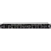
| Product Type | Two Channel Discrete Transistor FET Based Compressor/Limiter |
| Model | ART TransY |
| Dimensions (HxWxD) | 1.75" x 19.0" x 9.5" (44mm x 483mm x 241mm) |
| Depth (with power connector) | 11.6" (295mm) |
| Weight (with power supply) | 7.95 lbs (3.62 kg) |
| Power Supply | External, 48V DC, 10W; Input: 85-250 VAC, 50-60 Hz |
| Power Cord | IEC, with locking connector |
| Inputs | Balanced XLR and 1/4" TRS (line level -30dBm to +20dBm) |
| Outputs | Balanced XLR and 1/4" TRS (transformer coupled) |
| Detector Loop | 1/4" TRS input and output for external control (ducking, EQ) |
| Controls | Threshold, Ratio (1.2:1 to ∞:1 in 12 steps), Attack (0.5ms-100ms), Release (50ms-3s), De-Esse (0 to -16dB @6kHz), Output, Meter Source, Link, Bypass, Ground Lift, +4/-10 switch |
| Indicators | Gain reduction LED meter (10 segments), Level LED meter (10 segments, input or output) |
| Frequency Response | 15-100kHz ±0.5dB |
| THD | <0.05% (20-20kHz, typical) |
| CMRR | 80dB (typical) |
| Input Impedance (Balanced) | 33kΩ |
| Output Impedance (Balanced, +4/-10) | 110Ω / 250Ω |
| Maximum Input Level (+4/-10) | +21dBu / +9dBu |
| Maximum Output Level (+4/-10) | +21dBu / +9dBu |
| Equivalent Input Noise (+4/-10) | -90dBu / -102dBu ("C" weighted) |
| Chassis | Steel, painted finish, 1U rack-mountable |
| Safety Features | Hardwire bypass (works without power), grounding switch, polarized plug; do not open chassis; avoid moisture and heat |
| Maintenance | Clean exterior with dry cloth; no user-serviceable parts; refer service to qualified personnel |
| Spare Parts / Repairability | Contact ART support for service; warranty covers defects; power cord and supply replaceable |
| Warranty | 3 years parts and labor (USA); register online |
Frequently Asked Questions - TransY ART
User questions about TransY ART
0 question about this device. Answer the ones you know or ask your own.
Ask a new question about this device
Download the instructions for your Processor in PDF format for free! Find your manual TransY - ART and take your electronic device back in hand. On this page are published all the documents necessary for the use of your device. TransY by ART.
USER MANUAL TransY ART
APPLIED RESEARCH AND TECHNOLOGY
IMPORTANT SAFETY INSTRUCTIONS – READ FIRST


This symbol, whenever it appears, alerts you to the presence of uninsulated dangerous voltage inside the enclosure. Voltage that may be sufficient to constitute a risk of shock
This symbol, wherever it appears, alerts you to important operating and maintenance instructions in the accompanying literature. Please read manual.
Read instructions: Retain these safety and operating instructions for future reference. Heed all warnings printed here and on the equipment. Follow operating instructions printed in this user guide.
Do not open: There are no user serviceable parts inside. Refer any service work to qualified technical personnel only.
Power sources: Only connect unit to mains power of type marked on rear panel. Power source must provide a good ground connection.
Power cord: Use the power cord with sealed mains plug appropriate for your local mains supply as provided with the equipment. If the provided plug does not fit into your outlet consult your service agent. Route the power cord so that it is not likely to be walked on, stretched or pinched by items placed upon or against.
Grounding: Do not defeat the grounding and polarization means of the power cord plug. Do not remove or tamper with the ground connection on the power cord.
Ventilation: Do not obstruct the ventilation slots or position the unit where the air required for ventilation is impeded. If the unit is to be operated in a rack, case or other furniture ensure that it is constructed to allow adequate ventilation.
Moisture: To reduce the risk of fire or electrical shock do not expose the unit to rain, moisture, or use in damp or wet conditions. Do not place a container of liquid on it, which may spill into any openings.
Heat: Do not locate the unit in a place close to excessive heat or direct sunlight, as this could be a fire hazard. Locate the unit away from any equipment, which produces heat such as: power supplies, power amplifiers and heaters.
Environment: Protect from excessive dirt, dust, heat, and vibration when operating and storing. Avoid tobacco ash, drink spillage and smoke, especially that associated with smoke machines.
Handling: To prevent damage to the controls and cosmetics avoid rough handling and excessive vibration. Protect the controls from damage during transit. Use adequate padding if you need to ship the unit. To avoid injury to yourself or damage to the equipment take care when lifting, moving or carrying the unit.
Servicing: Switch off equipment and unplug the power cord immediately if it is exposed to moisture, spilled liquid, objects fallen into opening, the power cord or plug becomes damaged during a lightning storm, or if smoke odor or noise is noted. Refer servicing to qualified technical personnel only.
Installation: Install the unit in accordance with the instruction printed in the user manual.
TransY
TWO CHANNEL DISCRETE TRANSISTER FET BASED COMPRESSOR/LIMITER
IMPORTANT SAFETY INSTRUCTIONS – READ FIRST......II
INTRODUCTION....1
Key Features Include: 1
INSTALLATION 2
Unpacking 2
AC Power Hookup 2
Analog Audio Connections....2
REAR PANEL connections and controls ....3
Balanced Inputs....3
Balanced Outputs 3
Detector Loop....3
Output Ground switch....3
FRONT PANEL CONTROLS and INDICATORS....4
Bypass Switch 4
Threshold Control 4
Ratio Control....4
Attack Control 5
Release Control....5
De-Esse Control 5
Output Control 5
Gain Attenuation LED Meter 5
Level LED Meter 5
Meter Source switch 5
The Link Switch 6
Power 6
APPLICATIONS....6
Compressor/ Limiter 6
Stereo Mix and Mastering....6
Vocal and Instrument Leveling....7
Ducking 7
WARRANTY INFORMATION......8
Limited Warranty (USA only) 8
Online Registration 8
Exclusions 8
Service 9
SPECIFICATIONS ....10
LIST OF FIGURES
Fig. 1 - Rear Panel....3
Fig. 2 - Front Panel controls....4
INTRODUCTION
The TransY compressor/limiter features a discrete, low noise transistor audio path using a Field Effect Transistor for level control producing incredible detail. The unique feed forward detector topology and the servo FET drive circuitry provide a new level of flexibility and tone. The unit can be set to control audio levels from smooth and unobtrusive to full-blown deep sustain.
From the Active balanced input to the transformer-coupled output, the TransY abounds with easily adjustable reliable, repeatable functions due to the attention to detail in the design. The TransY adapts to a multitude of applications with its' +4/-10 level switch. A wide range of adjustments are available through the front panel controls always producing a musical result. Even the universal power supply adapts to line voltages allowing you to tour the world or connect to portable power sources without interruption.
Apply the TransY as your secret weapon from playing out live to recording and mastering. The TransY can handle whatever you throw at it producing a professional result. Master your unique sound with the TransY.
Key Features Include:
- Low noise, low THD discrete transistor audio path for incredibly detailed sound.
- Unique servo controlled FET gain reduction circuit.
• Rotary Slope switches provide reliable, repeatable results. - De-esser reduces sibilance when compressing vocals.
- Detector loop with separate input and output jacks allows contoured compression.
• 10-segment peak sensitive Level meter can monitor either the Input or output.
• High resolution LED Gain Reduction. - Custom Output Transformer reduces ground noise and maintains level for balance/unbalanced connections.
- Hardwire bypass simplifies troubleshooting, even when power is lost.
- +4/-10 I/O switch optimizes the S/N and operation with a wide range of equipment.
- Link for stereo mode makes all CH1 controls the Master.
- Universal External supply with locking connector reduces noise and provides uninterrupted operation over a wide range of line voltages.
- Rugged, reliable steel chassis shields the preamp from external noise.
• 3-year parts and labor warranty.
INSTALLATION
The ART TransY may be used in a wide variety of applications and environments. Housed in a rack-mountable, all-steel enclosure, the unit is designed for continuous professional use. Mounting location is not critical. However for greater performance and reliability, we recommend that users not place the unit on top of power amps, or other sources of heat and/or strong magnetic fields.
Unpacking
The TransY was packed with care at the factory. The shipping carton was designed to protect it during initial shipment. Please retain this carton for use in transporting TransY when it is not installed in a rack, or in the unlikely event that the TransY requires servicing. The shipping carton should contain:
The TransY
The user's guide
48V Power supply
IEC power cord
AC Power Hookup
TransY has an external power supply designed to operate from 85 to 250VAC, 50 to 60Hz. Units manufactured for use outside of the United States have been modified to comply with the required electrical specifications for the country of use. Under no circumstances should the power cable be altered. If the cable becomes cut or damaged, discontinue its use and have it replaced before operating TransY.
The power source must provide a good ground connection, and the ground pin on the mains plug should never be defeated.
Analog Audio Connections
Audio connections to and from TransY are:
$$ \begin{array}{l l} \text {Balanced input: [XLR]} & \text {Pin 2 = Hot (+) , Pin 3 = Cold (-) , Pin 1 = Ground} \ & \text {[1 / 4 - inch] Tip = Hot (+) , Ring = Cold (-) , Sleeve = Ground} \end{array} $$
$$ \begin{array}{l} \text {Balanced output:} \ \quad \begin{array}{l} [ X L R ] \quad \text {Pin 2 = Hot (+), Pin 3 = Cold (-), Pin 1 = Ground} \ [ 1 / 4 - i n c h ] \text {Tip = Hot (+), Ring = Cold (-), Sleeve = Ground} \end{array} \end{array} $$
$$ \text { Detector output: } \quad [ 1 / 4 - \text { inch } ] \text { Tip } = \text { Hot } (+), \text { Ring }, \text { Sleeve } = \text { Ground } $$
$$ \text { Detector input: } \quad [ 1 / 4 - \text { inch } ] \text { Tip } = \text { Hot } (+), \text { Ring }, \text { Sleeve } = \text { Ground } $$
Unbalanced 1/4-inch cables may be used on the balanced inputs and outputs with no damage to TransY however, we strongly recommend users use a balanced connection whenever possible to reduce noise. We recommend using only high-quality cables equipped with the appropriate connectors.
REAR PANEL connections and controls
Balanced Inputs
The TransY provides both an XLR and 1/4-inch input jack. These jacks are balanced, but the 1/4-inch jack can be used with unbalanced signals by simply plugging in an unbalanced cable.
The inputs are designed for use with line level signals ranging from -30dBm to +20dBm. While it is possible to plug an instrument directly into the TransY, it is desirable to run the instrument into a preamp ahead of the unit. This will provide a stronger signal and will keep noise to a minimum. Microphones must connect through a microphone preamplifier (like the ART Pro MPA II) before connecting into the TransY.
NOTE: The TransY has a passive (hardwire) bypass. This means that the bypass works even if the power is off.
Balanced Outputs
The analog output of the TransY is available on both a 1/4-inch TRS balanced jack and an XLR jack. This output is transformer balanced. The output has a low impedance for driving long lines.
“0” on the output meter corresponds 0dBu (.775 VRMS) at the output jacks when the I/O switch is set to +4 and -10dBV when set to -10.
Detector Loop
The Detector loop is an insert point between the buffered input signal and the Detector of the compressor.
Connecting an EQ to process this signal can contour the compressor's response when gain reduction is present.
Connect an audio signal to the Detector Loop Input and have the TransY reduce gain when a signal is present to provide Ducking (see the APPLICATIONS section for more information).
Output Ground switch
The Output Ground switch allows you to disconnect the input ground from the output jack. This is useful in eliminating ground loops.

Fig. 1 - Rear Panel
FRONT PANEL CONTROLS and INDICATORS
Bypass Switch
The TransY BYPASS switch physically connects the input jack to the output jack on each respective channel (also known as a hardwire bypass). The analog signal still passes from input to output if the Bypass switch is in the out position, even when power is off.
Threshold Control
The THRESHOLD control sets the point at which the TransY will act on a signal. Turning this control counter-clockwise lowers the threshold (adding more compression to a signal). Turning this control clockwise raises the threshold.
Proper setting of the INPUT THRESHOLD control is dependent on the input signal. The easiest way to set this control is to start with the control fully clockwise. Slowly turn the control counter-clockwise (lowering the threshold) until the yellow (0) LED light on the COMPRESSOR ATTENUATION meter begins to light. Next adjust the control (either lower or higher) for the desired amount of compression.
Use the attenuation meter as a visual guide to the amount of compression applied.
Ratio Control
The RATIO Control selects the “amount” of compression applied to the input signal once that signal reaches or exceeds the threshold. This compression amount is expressed as a ratio of input to output. For example if a 4:1 compression ratio is chosen, for every 4dB over the threshold the input signal rises, the output level only rises by 1dB. In this case if the input signal increased 12dB over the threshold, the output level would only rise by 3dB.
In general, compression ratios of 10:1 and greater are considered "limiting". The TransY may be used as either a compressor or a limiter with all of the following:
In a mixer's channel insert points.
Between a microphone preamp and signal processors.
Between pre-amplified electronic musical instruments (synthesizers, guitars, bass, samplers, acoustic instruments with pickups) and other line-level equipment.

Fig. 2 - Front Panel controls
Attack Control
The ATTACK control sets the time it takes the Compressor/Limiter to respond to increases in signal level (by reducing gain) and shape the front end of the dynamics envelope.
One example is to listen to a snare hit and adjust the ATTACK control. A short attack makes the snare sound “thin”. As the attack time goes longer (the knob is turned clockwise) more of the thump in the compressed snare can be heard. The downside is that this creates an overshoot, or “transient”, the length of which is the time set by the ATTACK control.
Overshoots less than 1 mSec. are very hard to hear even when they are clipped. If the ATTACK is set too fast, the gain may be reduced too much and thereby create a pumping sound ^1 .
Release Control
The RELEASE control sets the time the Compressor/Limiter takes to increase the gain after the input level drops.
Longer settings maintain the dynamics of the input signal, while shorter settings reduce the dynamics. Shorter settings will also increase the apparent reverberation, and at extreme gain reduction settings, lead to breathing artifacts ^2 .
De-Esse Control
De-essing refers to reducing the "s" and "sh" sounds level that is be increased when adding compression. The TransY De-esser control lowers the threshold of compression of a narrow band of frequencies to maintain a more natural level of sibilance as you increase compression.
Output Control
The OUTPUT control adjusts the Overall gain of the TransY.
The Channel 1 knob always controls the output level of Channel 1, but can also serve as a master output level when the Link Mode is active.
Gain Attenuation LED Meter
The attenuation meter displays the TransY compressor/limiter action. The meter covers a very large range while offering high resolution. The yellow (0) LED illuminates when the input signal reaches or exceeds the compressor detector threshold setting (Threshold control) and results in a reduction of 1 dB or more.
Level LED Meter
This meter displays the signal level present at the output of the unit. "0" on the meter corresponds to 0dBu (.775 VRMS) at the output jacks when the I/O switch on the rear panel is set to +4 and -10 dBV (.194 VRMS) when set to -10.
Meter Source switch
This switch selects the source for the LED level meter. When "out" the output signal is monitored. Depressing the switch displays the signal level present at the input of the unit.
The Link Switch
The two channels of the TransY can be configured for stereo operation by depressing the LINK switch. Link Mode connects the gain reduction of the two channels together for stereo operation. The Detector signals of the two channels are summed so either channel's signal can trigger gain reduction. Channel 1's controls (THRESHOLD, RATIO, ATTACK, RELEASE, DE-ESSE, OUTPUT) become the master and Channel 2's controls are ignored. Link Mode ensures that each channel of the stereo input signal is processed identically to prevent any shifting or distortion of the stereo image.
All of the switches (Bypass, Meter Source, +4/-10, Ground Lift) remain independent in link mode.
Power
The POWER switch turns the power on and off to the unit. The TransY should be turned “on” with all monitor levels turned down to protect against any thumping caused by power up. Likewise, the TransY should be turned off only after turning all monitor levels down. Power on the TransY before any monitoring outputs or power amps are turned on.
If the TransY fails to power up when the POWER switch is turned on, check to see that its power cord is plugged into an active outlet. If the unit still fails to operate properly, turn it off and unplug it.
APPLICATIONS
Compressor/ Limiter
The main application of the TransY is to control the dynamic range of an audio signal. Plug a line level (post preamplifier or other gain stage) source into either input, and set the threshold and output controls to provide the desired amount of compression to the input signal.
To keep the compression effects to a minimum, adjust the THRESHOLD and RATIO controls such that the Compressor Attenuation meter reads 10dB or less.
Stereo Mix and Mastering
Because of its low noise and excellent tonal qualities, the TransY is ideal for processing mixes when recording. Used as a mastering device, the TransY is capable of adding volume and impact to the overall signal level. The TransY is ideal for live use as well.
Putting the unit into link mode simplifies the control usage while maintaining the stereo image of the source material. The knobs on Channel 1 override CH2's controls.
The TransY really does a good job of controlling the peak content when setting the attack and release short and the Ratio to :1 . Make sure not to set the Threshold too low however. Only 6-10 dB indicated on The Compressor Attenuation meter is required to maximize the level of digital recordings.
Vocal and Instrument Leveling
The musical nature of the TransY makes it ideal for use on a wide range of instruments and vocals. Place the TransY into a channel insert, after a preamplifier, or in line with the direct output of a mixer channel. Adjust the controls of the TransY to achieve the desired amount of compression.
A good starting point for speech is a Ratio of 2:1 and gain reduction of 3-9dB. Adding sustain to instruments requires more aggressive settings for ratio (start at 4:1) and threshold. Gain reduction in the 15dB range is not uncommon.
Vocal processing may require tailoring of the detector response to prevent excessive sibilance. Rotate the De-esser control clockwise to reduce vocal sibilance.
Ducking
One application of ducking is muting the background music whenever someone talks into a mic. Simply connect the background music to be ducked to the audio input of the TransY and connect the line level buffered mic signal to the Detector Loop jack. Set the RATIO control to :1 Adjust the THRESHOLD control for the amount of muting required when someone is talking into the mic. Set the ATTACK control to 1 to 2 mSec to guarantee the music fades off quickly. Adjust the RELEASE control to set the time it takes to fade the music back in after there is no mic signal.
For a stereo music source, depress the LINK switch.
WARRANTY INFORMATION
Limited Warranty (USA only)
Applied Research and Technology will provide warranty and service for this unit in accordance with the following warrants:
Applied Research and Technology, (A R T) warrants to the original purchaser that this product and the components thereof will be free from defects in workmanship and materials for a period of three years from the date of purchase. Applied Research and Technology will, without charge, repair or replace, at its option, defective product or component parts upon prepaid delivery to the factory service department or authorized service center, accompanied by proof of purchase date in the form of a valid sales receipt.
Online Registration
Please go to www.artproaudio.com. Select "Support", then "Product Registration" input your information here.
Exclusions
This warranty does not apply in the event of misuse or abuse of the product or as a result of unauthorized alterations or repairs. This warranty is void if the serial number is altered, defaced, or removed.
A R T reserves the right to make changes in design or make additions to or improvements upon this product without any obligation to install the same on products previously manufactured.
A R T shall not be liable for any consequential damages, including without limitation damages resulting from loss of use. Some states do not allow limitations of incidental or consequential damages, so the above limitation or exclusion may not apply to you. This warranty gives you specific rights and you may have other rights, which vary from state to state.
For units purchased outside the United States, an authorized distributor of Applied Research and Technology will provide service.
Service
The following information is provided in the unlikely event that your unit requires service.
- Be sure that the unit is the cause of the problem. Check to make sure the unit has power, all cables are connected correctly, and the cables themselves are in working condition. You may want to consult with your dealer for assistance in troubleshooting or testing your particular configuration.
- If you believe that the ART unit is at fault, go to www.artproaudio.com.
- Select "Support", then "Return Authorization Request" to request a return authorization number.
- If you are returning the unit for service, pack the unit in its original carton or a reasonable substitute. The original packaging may not be suitable as a shipping carton, so consider putting the packaged unit in another box for shipping. Print the RA number clearly on the outside of the shipping box. Print your return shipping address on the outside of the box.
- Include, with your unit, a note with the RA number and your contact information, including a return shipping address (we cannot ship to a P.O. box) and a daytime phone number, and a description of the problem, preferably attached to the top of the unit. Also include a copy of your purchase receipt.
Please fill in the following information for your reference:
Date of purchase ____
Purchased from ____
Serial Number ____
SPECIFICATIONS
Max input level
Balanced, +4/-10 +21dBu / +9dBu
Detector input +20dBu
Input Impedance
Balanced input / detector input 33k Ω / 2M Ω
Max Output level
Balanced, +4/-10 +21dBu/ +9dBu
Detector +20dBu
Output Impedance
Balanced, +4/-10 110 Ω / 250 Ω
Detector output 270 Ω
Slope 1.2:1 to :1, selectable in 12 steps
De-Esser 0 to -16dB @6kHz
Attack time 0.5 mSec. to 100 mSec.
Release time 50mSec. to 3 Sec.
Frequency response 15-100kHz ± 0.5dB
T.H.D. <0.05% typ. 20-20kHz
C.M.R.R. 80dB typ.
Equivalent Input Noise, +4/-10 -90dBu/ -102dBu "C" wtd.
Power supply
Input requirements USA - 85 to 250 VAC/ 50-60 Hz
Export units configured for country of destination.
Output requirements 48 V dc, 10 Watts
Mechanical
Chassis Steel, Painted finish Dimensions (H,W,D) 1.75-inch x 19.0-inch x 9.5-inch
44mm x 483mm x 241mm
Weight (w/supply) 7.95 lbs., 3.62kg.
Note: With the locking power supply plug connected, the depth increases to 11.6-inch (295mm) total
Note: 0 dBu = 0.775Vrms
ART maintains a policy of constant product improvement. Therefore, specifications are subject to change without notice.

APPLIED RESEARCH AND TECHNOLOGY
www.artproaudio.com
E-mail: support@artproaudio.com
© 2018 Applied Research & Technology/ Yorkville Sound


- IMPORTANT SAFETY INSTRUCTIONS – READ FIRST
- TransY
- TWO CHANNEL DISCRETE TRANSISTER FET BASED COMPRESSOR/LIMITER
- IMPORTANT SAFETY INSTRUCTIONS – READ FIRST......II
- INTRODUCTION....1
- INSTALLATION 2
- REAR PANEL connections and controls ....3
- FRONT PANEL CONTROLS and INDICATORS....4
- APPLICATIONS....6
- WARRANTY INFORMATION......8
- Service 9
- SPECIFICATIONS ....10
- LIST OF FIGURES
- INTRODUCTION
- Key Features Include:
- INSTALLATION
- Unpacking
- AC Power Hookup
- Analog Audio Connections
- REAR PANEL connections and controls
- Balanced Inputs
- Balanced Outputs
- Detector Loop
- Output Ground switch
- FRONT PANEL CONTROLS and INDICATORS
- Bypass Switch
- Threshold Control
- Ratio Control
- Attack Control
- Release Control
- De-Esse Control
- Output Control
- Gain Attenuation LED Meter
- Level LED Meter
- Meter Source switch
- The Link Switch
- Power
- APPLICATIONS
- Compressor/ Limiter
- Stereo Mix and Mastering
- Vocal and Instrument Leveling
- Ducking
- WARRANTY INFORMATION
- Limited Warranty (USA only)
- Online Registration
- Exclusions
- Service
- Please fill in the following information for your reference:
- SPECIFICATIONS
- Max input level
- Input Impedance
- Max Output level
- Output Impedance
- Power supply
- Mechanical
Brand : ART
Model : TransY
Category : Processor