OTT-CONTROLLER - Controller Ikan - Free user manual and instructions
Find the device manual for free OTT-CONTROLLER Ikan in PDF.


| Product Type | PTZ Camera Controller |
| Brand | Ikan |
| Model | OTT-CONTROLLER |
| Dimensions | 320 x 180 x 100 mm (12.6 x 7.1 x 3.9 in) |
| Power Supply | DC 12V 1A (±10%) |
| Power Consumption | 0.6W Max |
| Operating Temperature | 32°F - 122°F (0°C - 50°C) |
| Storage Temperature | -4°F - 158°F (-20°C - 70°C) |
| Display | LCD screen |
| Joystick Control | Four-dimensional joystick with zoom (Tele/Wide) rotation |
| Ethernet Port | 1 x RJ45 |
| Control Protocols | VISCA, IP VISCA, ONVIF, PELCO (PELCO-D, PELCO-P) |
| Serial Interfaces | RS422 and RS232 |
| Network Configuration | Dynamic (DHCP) or Static IP |
| PTZ Speed Range | 1 (Slow) to 8 (Fast) |
| Presets | Set, Call, Delete (up to 255 presets via number keys) |
| Camera Quick Select | 4 buttons (CAM1 - CAM4) for quick switching |
| Search Function | ONVIF mode only, scans LAN for devices |
| Web Interface | Web page configuration (default IP, admin/empty password) |
| Firmware Upgrade | Via web interface, auto reboot after update |
| Language Options | English and Chinese |
| Button Sound Prompts | On/Off toggle |
| Back Panel Interfaces | RS422, RS232, Ethernet, DC 12V power input, Power switch |
| Functions | Auto Focus, Auto Aperture, Auto White Balance, Camera OSD, Custom F1/F2 |
Frequently Asked Questions - OTT-CONTROLLER Ikan
User questions about OTT-CONTROLLER Ikan
0 question about this device. Answer the ones you know or ask your own.
Ask a new question about this device
Download the instructions for your Controller in PDF format for free! Find your manual OTT-CONTROLLER - Ikan and take your electronic device back in hand. On this page are published all the documents necessary for the use of your device. OTT-CONTROLLER by Ikan.
USER MANUAL OTT-CONTROLLER Ikan
natural_image
Black industrial control device with rotary buttons and a digital display (no visible text or symbols)Precautions
- What is the function of CAM NUM when adding a network device?
CAM NUM will be associated and bound with the currently entered IP and port information.
It will quickly switch to the CAM NUM bound device when adding a device with the “CAM” button.
- How do I enter an IP address?
The camera controller doesn't have a “.” button, so please enter the IP address with four segments.
Take the IP address 192.168.0.1 for example. It will automatically jump to next segment when finished inputting a segment with three numbers, 192 and 168; but after inputting a segment with only one number, 0, you must move the joystick rightward to switch over to the next segment to continue inputting.
- How do I clear while in input mode?
Move the joystick leftward to clear the input information.
- The home page of each mode refers to the displayed page when the controller initialization is complete.
In IP VISCA and ONVIF Mode, if you see the prompts of “Visca!” and “Onvif!”, the IP address displayed on the screen is local IP address of the controller. While the prompts of “Visca:” and “Onvif:” are shown on the page, the IP address displayed on-screen belongs to the connected device.
Table of Contents
Precautions 2
- Product Overview
1.1 Product Features
1.2 Wiring Diagram 4
1.3 Technical Specifications 5
- Function Description 5
2.1 Button Description
2.2 Rocker Switch and Knob 7
2.3 Joystick Control 7
2.4 Terminal Description of Back Panel Interfaces 8
- Local Settings (SETUP) 8
3.1 Basic Settings 8
3.2 VISCA & IP VISCA Mode Shared Setting 9
3.3 IP VISCA Mode Setting 9
3.4 VISCA Mode Setting
3.5 PELCO Mode Setting 9
3.6 ONVIF Mode Setting 10
- Connection and Control 10
4.1 Connection and Control in ONVIF Mode 10
4.2 Connection and Control in IP VISCA Mode 11
4.3 Control in VISCA & PELCO Mode 11
- Web Page Configuration 1
5.1 Home Page 11
5.2 LAN Settings 12
5.3 Upgrade 13
Support, Warranty, Copyright 14
1. Product Overview
1.1 Product Features
Two IP control modes: IP VISCA & ONVIF
Two analog control modes: RS422 & RS232
Three Control Protocols: VISCA, ONVIF and PELCO
1.2 Wiring Diagram
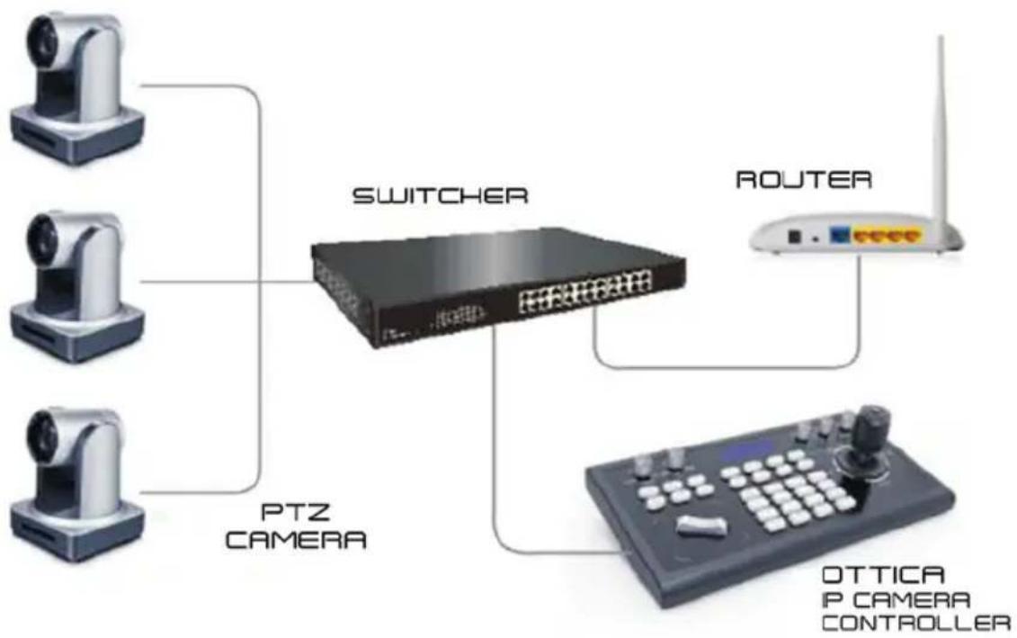
Both the Controller and PTZ camera must be connected to the same LAN. The IP addresses of both the PTZ Camera and Controller must operate within the same network segment.
For example:
192.168.1.123 is within the same segment as 192.168.1.111
192.168.1.123 is not within the same segment as 192.168.0.125
flowchart
graph TD
    A["Camera"] --> B["Switcher"]
    C["Camera"] --> B
    D["Camera"] --> B
    B --> E["Router"]
    B --> F["PTZ CAMERA"]
    F --> G["PTTICA IP CAMERA CONTROLLER"]
1.3 Technical Specifications
| Ethernet 1 x Ethernet Port | |
| Joystick | Four-dimensional joystick control (up, down, left, right) Rotatable for zooming Tele/Wide |
| Connection Lead | |
| Display LCD | |
| Prompt Tone Button Sound Prompts On/Off | |
| Power Supply DC 12V1A ± 10% | |
| Power Consumption 0.6 W Max | |
| Operating Temperature 32°F-122°F | |
| Storage Temperature -4°F-158°F | |
| Dimensions 320 x 180 x 100mm | |
2. Function Description
2.1 Bunton Description
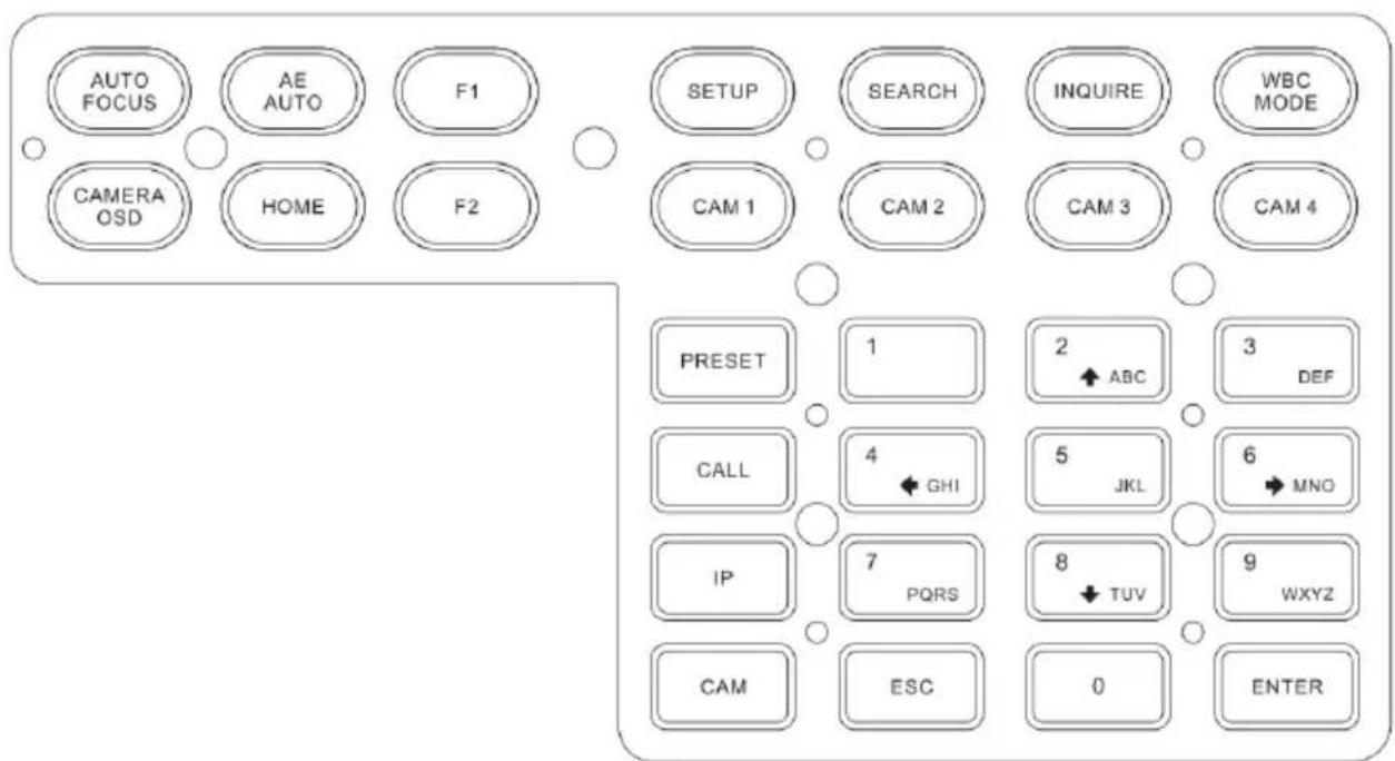
[AUTO FOCUS] Sets the camera in auto focus mode with this button. It will light up when the camera is in manual focus mode.
[AE AUTO] (Auto Aperture) Set the camera in automatic aperture mode with this button. It will light up when camera is in manual aperture mode.
[CAMERA OSD] Call/Close the camera OSD
[HOME] Returns the camera back to home position if camera OSD is off. When the camera OSD is on, the home button confirms the function of camera OSD.
[F1]\~[F2] Custom function buttons. In VISCA and IP VISCA modes.
[SETUP] Local settings button, modifies & views local settings. Navigate menus using Joystick.
[SEARCH] Search for all available devices with ONVIF protocol in the LAN (only in ONVIF Mode).
[INQUIRE] Check added devices.
[WBC MODE] (Auto White Balance) Sets the camera in auto white balance mode. Button will light up when camera is in manual white balance mode.
[CAM1]\~[CAM4] Quickly switch device button: Quickly switch to CAM NUM 1-4 devices (ONVIF, IP VISCA), or to address code 1-4 devices (VISCA, PELCO).
[PRESE] Short presses will enable you to set presets; long presses will enable you to delete presets. Use the number keys and the "ENTER" button, when setting or deleting presets.
[CALL] Use the number keys and "ENTER" button to move the camera to a preset.
[IP] Manually adds network devices (only in ONVIF and IP VISCA modes). Use the "ENTER" button to confirm each step of the setup.
[CAM] In IP VISCA and ONVIF modes, it will quickly switch to the CAM NUM bound device when adding a device via CAM.
In VISCA and PELCO modes, it will switch to the address code when entering a certain address. Use the “ENTER” button to confirm each step of the setup.
[1]\~[9] Number keys of 0,1,2,3,4,5,6,7,8,9.
2,4,6,8 also serve as directional keys, which can control pan and tilt rotation, and camera OSD.
[ESC] Return
[ENTER] Confirm Button. Be sure to press this button to confirm any/all settings.
2.2 Rocker Switch and Knob
flowchart
graph LR
    A["NEAR"] --> B["FORCU"]
    C["FAR"] --> D["OPEN"]
    E["OPEN"] --> F["CLOSE"]
    G["IRIS"] --> H["R"]
    I["-"] --> J["+"]
    K["+"] --> L["B"]
    M["+"] --> N["PTZ SPEED"]
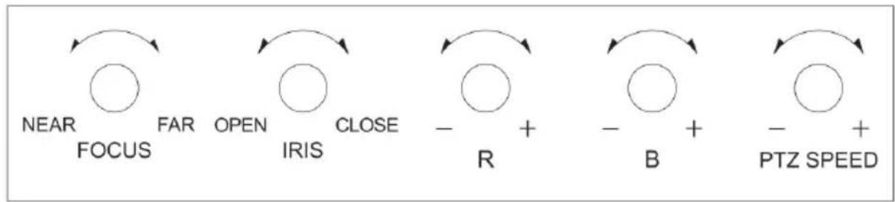
[NEAR] [FAR] Manually adjust the focal length.
[OPEN] [CLOSE] Manually adjust the aperture, OPEN(Aperture Plus)/CLOSE(Aperture minus)
[R-] [R+] Manually adjust the Red Gain
[B-] [B+] Manually adjust the Blue Gain
[PTZ SPEED-] [PTZ SPEED+] Adjust PTZ Speed 1-8: “-” = Slow. “+” = Fast.
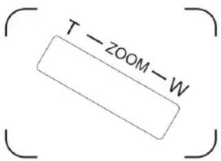
[T-ZOOM-W] Zoom Tele and Zoom Wide
2.3 Joystick Control
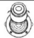 | Up | 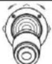 | Down | 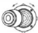 | Left |
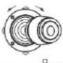 | Right | 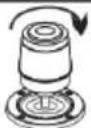 | Zoom In | 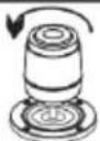 | Zoom Out |
2.4 Terminal Description of Back Panel Interfaces
Back Panel Details: RS422, RS232, DC-12V, Ethernet, Power Switch

| Number Label Physical Interface Description | |||
| 1 RS422 | Control Output(TA, TB, TA, TB) | Connect to RS422 bus of the camera:TA to camera RATB to camera RBRA to camera TARB to camera TB | |
| 2 Ground Control line ground | (G) Control signal Line ground | ||
| 3 ETHERNET Ethernet Port Network Connection | |||
| 4 DC-12V Power Input DV 12V Power Input | |||
| 5 POWER Power Switch Power ON / OFF | |||
3. Local Settings (SETUP)
3.1 Basic Settings
Move the joystick up and down to switch between basic settings. Move the joystick left or right to alter settings. Confirm settings with "ENTER" button.
- Delete Device
- Network Type: Dynamic and Static
- Button Sound Prompt: On and Off
- Language Setting: English and Chinese
- Mode: VISCA, IP VISCA, ONVIF, PELCO
- Local IP
- Version Information
- Restore Factory Settings
- Function Button 1 ("F1") Setup
- Function Button 2 ("F2") Setup
3.2 VISCA & IP VISCA Mode Shared Setting
- F1: Custom function for F1 button (VISCA command)
- F2: Custom function for F2 button (VISCA command)
Input custom name > ENTER > Input VISCA command
For example: If the command is 8101040702FF, then input 01040702 (0 can't be omitted)
3.3 IP VISCA Mode Setting
Delete the saved device:
Move the joystick up and down to view devices; Move the joystick rightward to view the device's port information; Move the joystick leftward to view the IP, CAM NUM information; ENTER to delete the selected device.
3.4 VISCA Mode Setting
Control Settings (set the baud rate for a certain address code):
Move the joystick up, down, left and right to switch addresses (1-7) > ENTER > Move the joystick left and right to switch baud rate > ENTER
EX: Select the address: 1 > ENTER > Select the baud rate: 9600 > ENTER
When the controller is switched to address 1, the control baud rate is 9600
3.5 PELCO Mode Setting
Control Settings (set the baud rate for a certain address code):
Move the joystick up, down, left and right to switch addresses (1-255) > ENTER > Move the joystick left and right to choose protocols > ENTER > Move the joystick left and right to switch baud rate > ENTER
EX: Select the address: 1 > ENTER > Select the protocol: PELCO-D > ENTER > Select the baud rate: 9600 > ENTER
When the controller is switched to address 1, the control baud rate is 9600, protocol is PELCO-D
3.6 ONVIF Mode Setting
Delete Saved Device:
Move the joystick up and down to view devices. Move the joystick rightward to view the device's port information. Move the joystick leftward to view the IP, CAM NUM information. Press "ENTER" to delete the selected device.
4. Connection and Control
4.1 Connection and Control in ONVIF Mode
Search and Add
In ONVIF mode, follow the steps below to add a LAN device to the PTZ controller:
- After the controller has obtained IP address, simply press the SEARCH button.
- All available devices with the ONVIF protocol in the LAN will be displayed on the controller when search process is complete.
- Move the joystick up/down to select the device. Press the "ENTER" button to confirm.
- It's required to enter the device's username, password and CAM NUM information when adding a device.
- Press the "ENTER" button to save.
- Alternatively, use the [IP] button to add a device manually.
- Press the "INQUIRE" button to view the added device. Move the joystick up/down to view the saved device (move the joystick rightward to view the port). Press the "ENTER" button to select a camera to control, or use the CAM button to connect and control.
4.2 Connection and Control in IP VISCA Mode
The Searching function is not available in IP VISCA mode, but you can manually add a device.
- Manually add device via the [IP] button.
- Press the "INQUIRE" button to view the added device. Move the joystick up/down to view the saved device (move the joystick rightward to view the port); Press the "ENTER" button to select a camera to control, or use the CAM button to connect and control.
4.3 Control in VISCA & PELCO Mode
Simply set the address code and baud rate to control. In PELCO Mode, correctly set the PELCO-D or PELCO-P protocol.
5. Web Page Configuration
5.1 Home Page
The Searching function is not available in IP VISCA mode, but you can manually add a device.
- Connect the controller and computer to the same LAN and enter the controller's IP address into the browser.
- Default username: admin | Password: empty
- Home page is as below:
![NET KEYBOARD [1] 192.168.5.163.2000 Add All Add Delete Del All Search Update Handle Device IP 192.168.5.163 Onvif Port 200 Cam Num 1 Username admin Password admin Save](/content/2026/05/954543/images/dc7bacb9399bff743b0fb3f7632b90130ba0ba9110b9e20cb24614b68c8ec2ea.jpg)
- The home page consists of three segments: Search Device List (green); Added Device List (blue) or Manually Add (yellow); Device Details (orange).
- Click the "Search" button to find ONVIF devices in the LAN. Devices will be displayed in the green frame automatically.
- Select the device in the "Search Device List", and click "Add" to complete. Press "Ctrl" for multiple selections.
- Select the device in the "Added Device List", and click "Delete" to complete. Press "Ctrl" for multiple selections.
- After successfully adding a device, click the IP address in the "Added Device List" to edit the account and port information of the device.
- After addition, deletion, and modification, click the "Save" button to confirm.
Note: A ny modification to the configuration on home page needs to be saved by clicking the "Save" button; otherwise any modifications are invalid.
5.2 LAN Settings
To modify the device IP access way and port parameters in LAN Settings, refer to image below:
Click save to confirm.
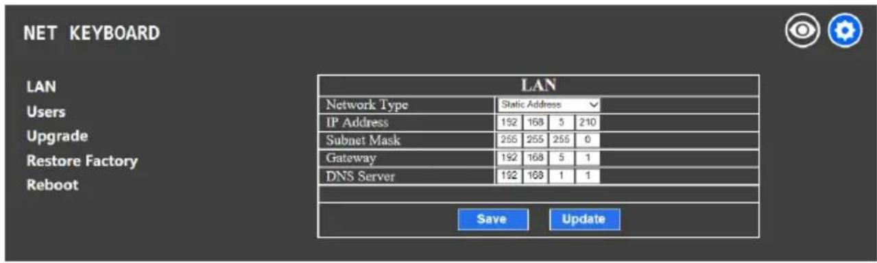
Dynamic address (default access way): the Controller will automatically acquire IP address from the router.
Static address: Change the network to static address when necessary; simply input the network segment information to modify.
5.3 Upgrade
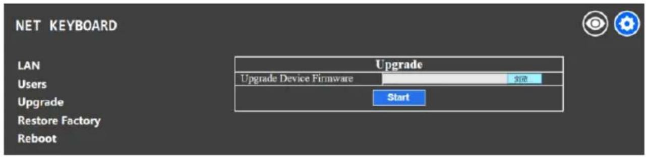
The upgrade function is available for maintenance and updates.
Choose the update file and click "start" to update the controller. It will auto reboot after updating.
Note: Do not operate the controller, shut the power off, or disconnect the device from the network during the upgrade process.
5.4 Restore Factory
Restore the controller to factory default settings when an unexpected failure occurs due to improper modifications. Please use factory restoration with caution.
5.5 Reboot
Click Reboot for maintenance if the controller has been running for a long period of time.
Learn More at www.ikancorp.com
Support
Contact email: support@ikancorp.com
CONDITIONS OF WARRANTY SERVICE
- Free service for one year from the day of purchase if the problem is caused by manufacturing errors.
- The components and maintenance service fee will be charged if the warranty period is expired.
Free service will not be provided in the Following Situations: (\*Even if the product is still within the warranty period.)
- Damage caused by abuse or misuse, dismantling, or changes to the product not made by the company.
- Damage caused by natural disaster, abnormal voltage, and environmental factors, etc.
©2020 Ikan International. All rights reserved.

- Precautions
- Table of Contents
- Precautions 2
- Product Overview
- Product Features
- Wiring Diagram
- Technical Specifications
- Function Description
- Bunton Description
- Rocker Switch and Knob
- Joystick Control
- Terminal Description of Back Panel Interfaces
- Local Settings (SETUP)
- Basic Settings
- VISCA & IP VISCA Mode Shared Setting
- IP VISCA Mode Setting
- VISCA Mode Setting
- PELCO Mode Setting
- ONVIF Mode Setting
- Connection and Control
- Connection and Control in ONVIF Mode
- Connection and Control in IP VISCA Mode
- Control in VISCA & PELCO Mode
- Web Page Configuration
- Home Page
- LAN Settings
- Upgrade
- Restore Factory
- Reboot
- Learn More at www.ikancorp.com
- Support
- CONDITIONS OF WARRANTY SERVICE
- Free service will not be provided in the Following Situations: (\*Even if the product is still within the warranty period.)
Brand : Ikan
Model : OTT-CONTROLLER
Category : Controller