
F50-ATS - Automatic transfer switch Furrion - Free user manual and instructions
Find the device manual for free F50-ATS Furrion in PDF.


| Product Type | RV Refrigerator |
| Model | F50-ATS |
| Brand | Furrion |
| Dimensions (H x W x D) | 24 x 24 x 24 inches |
| Weight | 45 lbs |
| Power Source | 12V DC / 120V AC / LP Gas |
| Cooling Capacity | 5.0 cu ft |
| Temperature Range | Freezer: 0°F, Fridge: 35°F to 50°F |
| Defrost | Automatic |
| Installation | Built-in (cutout required) |
| Controls | Electronic with digital display |
| Energy Consumption (DC) | 10-15 Amps |
| Energy Consumption (AC) | 1.5 Amps |
| Safety Features | Flame failure device, gas leak detection |
| Maintenance | Clean condenser coils annually, check door seals |
| Spare Parts | Available from Furrion dealers |
| Warranty | 2 years limited |
Frequently Asked Questions - F50-ATS Furrion
User questions about F50-ATS Furrion
0 question about this device. Answer the ones you know or ask your own.
Ask a new question about this device
Download the instructions for your Automatic transfer switch in PDF format for free! Find your manual F50-ATS - Furrion and take your electronic device back in hand. On this page are published all the documents necessary for the use of your device. F50-ATS by Furrion.
USER MANUAL F50-ATS Furrion
natural_image
Technical line drawing of an electronic device casing with internal components and mounting holes (no text or symbols)50amp 125/250V Automatic Transfer Switch
Furrions ATS is used to safely switch automatically between multiple power sources
Furrion's 50amp Automatic Transfer Switch with built in safe switch interlock system is used to automatically switch between two separate 125/25 Volt AC power sources, these power sources can be from a Generator, shore power cord or inverter.
The function of the Furrion Automatic Transfer Switch is to provide a safe and smooth switch over from an inverter or shore power cord automatically when a generator is started and brought online, the Furrion ATS offers the added feature of a mechanical interlock between contactors to ensure both contactors cannot be closed in parallel which could otherwise create an over voltage situation on the output line.
The electrical contacts in the transfer switch are normally in the open position, once AC voltage is applied to input 1 this will automatically close the contacts in contactor 1 and feeds the output line from the shore power cord or inverter.
Once AC power from the Generator is sensed by the transfer switch at Input 2 terminals, this will start a timer and automatically switch over to generator power supply after a 20-30 second delay which ensures the generator has sufficient time to run up to speed before electrical load is applied.
PLEASE READ ALL SAFETY INSTRUCTIONS BEFORE INSTALLING THIS TRANSFER SWITCH!
WHEN PROTECTED BY A MOLDED CASE CIRCUIT BREAKER RATED TO 50AMPS OR LESS, THIS LINE/GENERATOR SWITCH IS RATED TO 5000 SYMMETRICAL AMPS.
BEFORE PREFORMING MAINTENANCE OR INSTALLATION PLEASE ENSURE TO ISOLATE ALL POWER SOURCES!
! Ensure generator is shut off and auto start feature (if applicable) is isolated.
! Confirm external power cord is disconnected and stored in an area where it cannot mistakenly be plugged in.
! Confirm the inverter (if used) has been disconnected.
! Confirm with an AC/DC electrical tester that no voltage is present at any of the connections before beginning installation or maintenance.
Label all electrical parts with a warning tag to show work is in progress before beginning work.
Furrion warranties this transfer switch in the Continental Untied States of America and Canada from defects in materials or workmanship under normal use for 1 year from date of purchase.
There are 3 common installation configurations for the Furrion ATS series:
Configuration 1: Double power feed
This is the standard installation used between a shore power cord and generator.

flowchart
graph TD
    A["Shore Power Cord\n50Amp 125/250 VAC 12KW\nFurrion Pull Smart Plug Featured Below"] --> B["Furrion F50-ATS Transfer switch\nOutput feed\nInput 2"]
    C["DISTRIBUTION PANEL / BRANCH CIRCUITS"] --> B
    D["GENERATOR\n50Amp 125/250 VAC 12KW Generator"] --> B
    B --> E["Ground"]
Configuration 2: Triple power feed (same rating)
This configuration is used when a inverter is added to the system and requires automatic switch over. See Diagram 2 which illustrates this configuration

flowchart
graph TD
    A["Main Power Supply Wiring, with 50amp Sub Panel Inverter Feed."] --> B["DISTRIBUTION PANEL / BRANCH CIRCUITS"]
    A --> C["FURRION F50-ATS Transfer switch"]
    A --> D["POWER INVERTER MAX 6000W"]
    A --> E["SHORE POWER CORD 50Amp 125/250 VAC 12KW FURRION PULL SMART PLUG FEATURED BELOW"]
    A --> F["GENERATOR 50Amp 125/250 VAC 12KW Generator"]
    B --> G["Output feed"]
    C --> H["Output feed"]
    D --> I["Power Inverter"]
    E --> J["Power Inverter"]
    F --> K["Power Inverter"]
Configuration 3: Triple Power Feed (double distribution panel)
This configuration is used when it is required for multiple power sources to feed sub distribution panels

flowchart
graph TD
    A["Main Power Supply Wiring, with 30amp Sub Panel Inverter Feed."] --> B["Furrion F30-ATS Transfer switch"]
    B --> C["Output feed"]
    B --> D["DISTRIBUTION PANEL 1"]
    B --> E["DISTRIBUTION PANEL 2"]
    B --> F["POWER INVERTER MAX 3000W"]
    B --> G["DISTRIBUTION PANEL 1"]
    B --> H["SHORE POWER CORD 50Amp 125/250 VAC 12KW FURRION PULL SMART PLUG FEATURED BELOW"]
    B --> I["GENERATOR 50Amp 125/250 VAC 12KW Generator"]
    B --> J["Output feed"]
Warning:
The Furrion F50-ATS is not suitable to be used with Medical life support equipment.
For mounting and installing the transfer switch you will require:
3 x 1" Cable strain relief's
4 x Self tapping screws with a minimum length of 30mm to mount ATS box
1 x Torque screw driver with square head #2
1 x Philips screw driver #2
MOUNTING YOUR F50-ATS:
The Furrion ATS is best mounted indoors or in a location sheltered from outdoor elements.
The selected area must be free from the possibility of contaminates and away from water pipes, pumps, battery compartments and storage areas for flammable liquids.
Do not mount the ATS in a engine compartment.
The ATS mounting location must be accessible after installation is complete to facilitate future servicing, if possible mount the ATS close to power cord Point of entry or generator output.
Typical examples of mounting locations are:
Inside seat or bed compartments
Above or behind cabinets'
Under floor storage compartments, etc.
To mount the ATS box the 4 screw lugs on the outside of the box can be used to secure, the ATS box also has an alternative 4 screw holes inside the box which can also be used.
Punch out 3 of the large diameter cable strain holes on the side of the box in the directions which the cables will be fed from using a blunt object. Ensure to remove all plastic pieces of the punch out cable strain holes by rotating the ATS box upside down.
Hold the transfer switch to the desired position and using 4 self-tapping screws secure the transfer switch box. Ensure the switch is securely mounted so it cannot move or vibrate.
Once the ATS is securely mounted then screw in the 3 cable strains into the punch out holes and back off the cable strain screws.
50amp 125/250AC Wiring
Ground = Bare copper wire or green
Neutral = White
Live/Hot L1 = Black
Live/Hot L2 = Red
50amp 125VAC Wiring
Ground = Bare copper wire or green
Neutral = White
Live/Hot = Black
Using the quick reference wiring guide on the lid of the ATS box, arrange the wires to be fed into the ATS for connection at the corresponding terminals.
Generator in
Shore Power in
Line/feed out
Ensure to feed the wires through the cable strains when they enter to ATS box.
Shore power and generator cables should be fed into the ATS from the side marked on the box sticker.
The line out wires will enter the ATS from the opposite side.
See below diagram for wiring layout.
Strip 4" of outer jacket from each of the incoming cables.
Strip 1/2" of jacket from each of the wire conductors.
Connect the colored wires to the ATS terminals using the diagram above
Using your #2 (Robertson's) square head torque Screwdriver, tighten the terminal screws to 20in-lb minimum and 25in-lb maximum
Connect the chassis grounding 8AWG wire to the grounding terminal block on the inside of the transfer switch box. Use the 3/8" through hole to feed the wire through from the outside of the box directly to the terminal block.
Using your #2 Square Head Torque Screwdriver, tighten the grounding block terminal screws to 20in-lb minimum and 25in-lb maximum.
PLEASE READ THE FOLLOWING SAFETY INSTRUCTIONS...
Follow the below steps to test the function of the F50-ATS.
BEFORE TESTING:
Ensure air conditioning units and other high current users are switched off. It is harmful for the transfer switch to switch over power sources while under load.
Shut down all power sources to the RV
Label power sources clearly that testing is in progress.
If accessible, remove the lid of the ATS to visually check function.
ATS FUNCTION TESTING:
- Plug in the shore power cable and turn on the dockside shore power breaker, as soon as the shore side breaker is turned on you will hear a clunk noise immediately as the shore power contactor engages inside the ATS, power is then supplied to the RV from the ATS line out feed.
- Turn off the shore side power breaker to shut down power to the RV, you will hear a clunk as the Shore power contactor disconnects (keep the shore power cord connected with no power for further testing).
- Start the Generator in the RV and wait for it to run up to speed, as soon as power is fed to the ATS from the generator the green LED indicator light on the internal ATS PCB will illuminate, the ATS has a 20-30 second time delay before engaging the internal contactor to allow for the generator to warm up. After 20-30 seconds you will hear a clunk noise as the generator contactor engages inside the ATS, power from the generator is now supplied to the RV from the ATS line out feed.
- Shut down the generator
ATS SWITCHING TESTING:
To test the switching function after both function tests have passed:
- Turn on the shore cord shore side breaker to engage the shower power contactor, power is now being supplied to the RV by the shore power.
- Start the generator and wait for it to warm up, after 20-30 seconds you will hear a clunk as the unit automatically switches over power sources from shore power to generator.
- Turn off shore power from the shore side breaker and confirm the generator is feeding the line out, the power supply should not be interrupted by doing this.
- Turn on the shore power shore side breaker again which will engage the shore power contactor. While the shore power is still connected and on, then turn off the generator, this will then disengage the generator contactor and automatically switch to running on shore power feed.
TROUBLESHOOTING YOUR F50-ATS:
In the event of a problem with your F50-ATS, contact a qualified electrician for advice.
COMMON PROBLEMS:
Transfer switch will not switch over from Shore Power to Generator feed.
Possible cause: Bad PCB.
How to check: Open the transfer Switch lid so the PCB in visible, do not put your hands or touch anything parts inside the box.
Turn on the generator so electric is being fed to the ATS, using a multi meter check for correct voltage at the incoming generator wiring terminals.
If the correct power is being fed to the ATS from the Generator the ATS PCB's the green
LED illuminated. After 30 seconds if the contactor does not close
If the PCB's green LED is not illuminated while generator voltage is present indicates the PCB has been damaged and will need replaced.
Contact your nearest Furrion Dealer, RV OEM or email support@furrion.com
POSSIBLE CAUSES FOR F50-ATS PROBLEMS:
INGRESS OF FOREIGN OBJECTS INSIDE ENCLOSURE:
Reasons:
Poor installation can cause wood chippings, sawdust, metal filings, or other foreign matter to enter the case.
Unsuitable mounting position can cause condensation, moisture or dirt to enter the enclosure,
Potential Damage: Contactor does not function properly, burned out coils, Metal particles can cause fire or short the PCB.
FLUCTUATING POWER OR POWER SPIKES:
Reasons:
Lighting strikes,
Unbalance load at park,
Park Black outs
Utility service at park is undersized or located next to an industrial environment.
Potential Damage: burnt out contactor coils, PCB damage, pitted contacts, further damage to the RV.
LOW VOLTAGE POWER SUPPLY:
Reasons:
Bad or corroded electrical connection,
Extension cord length too long
Operating too much load for power available.
Park power supply insufficient
Potential Damage: Pitted contacts, burnt out contactor coils, further damage to the RV.
GENERATOR FEED:
Reasons:
Generator requires maintenance,
Generator Governors or throttle problems
Generator Auto Start/Stop failure.
Potential Damage: Burnt out contactor coils, PCB damage, pitted contacts, further damage to the RV.
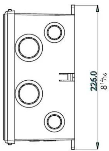
There are 2 options for mounting the Furrion F50-ATS:
Option One: Using the external lugs which are located on the outside of the box.
Mounting dimensions for the external lugs are:
Outer Lugs: 189 x 220mm (7 ^7 / 16 x 8 ^11 / 16 )
Option Two: Using the 4 x internal holes which are located on the inside of the box.
Mounting dimensions for the internal holes are:
Internal holes: 160 x 130mm ( 6^5/16 x 5^1/8 )



natural_image
Technical line drawing of a device casing with circular components and three dots on the side (no text or symbols)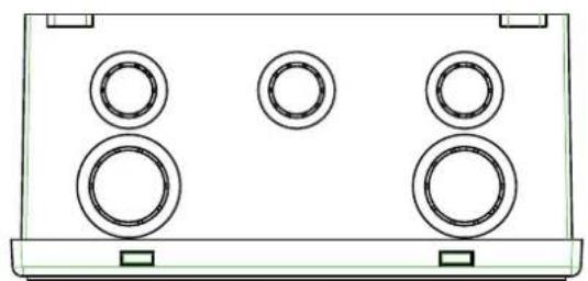
natural_image
Simple line drawing of a speaker grille with three circular buttons and two base stations (no text or symbols)FURRION
Furrion Innovation Center & Institute of Technology
• 52567 Independence Ct., Elkhart, IN 46514, USA • Toll free:1-888-354-5792
• Email: info@furrion.com
©2007-2018 Furrion Ltd. Furrion® and the Furrion logo are trademarks licensed for use by Furrion Ltd. and registered in the U.S. and other countries.
FURRION.COM
- 50amp 125/250V Automatic Transfer Switch
- PLEASE READ ALL SAFETY INSTRUCTIONS BEFORE INSTALLING THIS TRANSFER SWITCH!
- BEFORE PREFORMING MAINTENANCE OR INSTALLATION PLEASE ENSURE TO ISOLATE ALL POWER SOURCES!
- For mounting and installing the transfer switch you will require:
- MOUNTING YOUR F50-ATS:
- PLEASE READ THE FOLLOWING SAFETY INSTRUCTIONS...
- BEFORE TESTING:
- ATS FUNCTION TESTING:
- ATS SWITCHING TESTING:
- TROUBLESHOOTING YOUR F50-ATS:
- COMMON PROBLEMS:
- POSSIBLE CAUSES FOR F50-ATS PROBLEMS:
- INGRESS OF FOREIGN OBJECTS INSIDE ENCLOSURE:
- FLUCTUATING POWER OR POWER SPIKES:
- LOW VOLTAGE POWER SUPPLY:
- GENERATOR FEED:
- There are 2 options for mounting the Furrion F50-ATS:
- FURRION
- Furrion Innovation Center & Institute of Technology
Brand : Furrion
Model : F50-ATS
Category : Automatic transfer switch