
110CT425A-L - Sorbet maker Follett - Free user manual and instructions
Find the device manual for free 110CT425A-L Follett in PDF.


| Product Type | Countertop ice and water dispenser with integral ice machine |
| Model | 110CT425A-L |
| Ice Production Capacity | 425 lb (193 kg) per day |
| Electrical Requirements | 115 V/60 Hz/1 phase, 11.0 A (total system), dedicated 15 A circuit recommended |
| Shipping Weight | Approx. 290 lb (132 kg) for dispenser; base stand 140 lb (64 kg) |
| Dispensing Methods | Lever or SensorSAFE infrared touchless dispensing |
| Water Connections | 3/8" FPT water inlet, 3/4" MPT drain |
| Ambient Temperature Range | 50°F to 100°F (10°C to 38°C) |
| Water Temperature Range | 45°F to 90°F (7.2°C to 32°C) |
| Water Pressure | 10 to 70 PSI (0.7 to 5 bar) |
| Ventilation Clearances | 6" (15.2 cm) required at top; 6" (15.2 cm) sides advised for service |
| Ice Machine Type | Continuous auger-type with 425 lb/day capacity |
| Storage Hopper Capacity | Not specified; sufficient for 425 lb/day production |
| Special Features | SensorSAFE infrared dispensing, Quiet Night/Sleep cycle, cleaning switch |
| Cleaning Intervals | Weekly drain pan, monthly condenser, semi-annual deep cleaning/descaling |
| Safety Features | Automatic shut-off after 1 minute continuous dispensing, clean switch disable |
| Construction | Stainless steel exterior, NSF listed silicone sealant required for countertop installation |
| Warranty | Standard Follett warranty; service problems from lack of preventive maintenance not covered |
| Replacement Parts Availability | Full range of parts available: wheelmotor, sensors, chutes, solenoid, etc. |
| Installation Requirements | Level in both directions; countertop model requires bolting to counter with NSF sealant |
| Water Filtration Recommended | Follett water filter system required on ice machine inlet |
| Compliance | NEC and local electrical codes; use only Follett approved cleaners/sanitizers |
Frequently Asked Questions - 110CT425A-L Follett
User questions about 110CT425A-L Follett
0 question about this device. Answer the ones you know or ask your own.
Ask a new question about this device
Download the instructions for your Sorbet maker in PDF format for free! Find your manual 110CT425A-L - Follett and take your electronic device back in hand. On this page are published all the documents necessary for the use of your device. 110CT425A-L by Follett.
USER MANUAL 110CT425A-L Follett
Symphony Plus™ 110 Series Ice and Water Dispensers
Operation and Service Manual
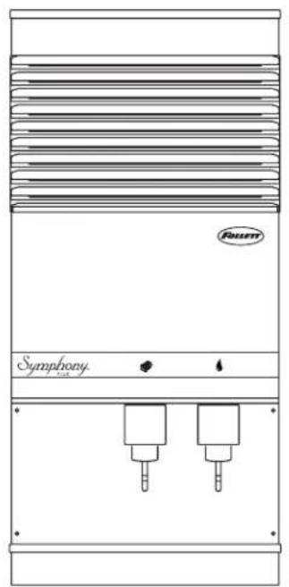
natural_image
Front view of a symphonic air conditioner unit with two cooling units and a brand mark (no text or symbols on the unit itself)110CT425A/W

110CR425A/W

natural_image
Line drawing of a symphonic water heater with two pressure dropers (no text or symbols)110FB425A/W
Following installation, please forward this manual to the appropriate operations person.
Contents
Welcome to Follett. 3
Before you begin. 3
Specifications 4
Electrical 4
Ambient 4
Plumbing. 4
Ventilation clearances....5
Approximate shipping weight 5
Installation....5
Before you begin. 5
Installing freestanding dispensers 5
Installing countertop dispensers....7
Installing RIDE ice machines 9
Installing top mount ice machines 10
User information 12
How the dispenser works.... 12
How SensorSAFE infrared dispensing works 12
Quiet Night™/Sleep cycle (does not apply to CR units) 12
Cleaning/descaling and sanitizing 12
Weekly 13
Monthly 13
Semi-Annually (more often if conditions dictate) 14
Ice Machine and Dispenser 14
Dispenser only 15
Service 18
Wiring diagram 18
Dispenser troubleshooting 20
Lever model troubleshooting guide 20
SensorSAFE model troubleshooting guide 21
Disassembly and replacement instructions.... 22
Ice transport tube replacement - Top mount units. 23
Ice transport tube replacement – Freestanding and RIDE models 23
Thermostat replacement....25
Replacement parts 26
Dispenser exterior....26
Wheelmotor and drive system 27
Dispense chute and splash panel (models with lever dispensing) 28
Dispense chute and splash panel (models with SensorSAFE infrared dispensing) 29
Electrical components 30
Hopper components 31
Ice transport tubing....32
Chilled water components 32
Dispenser plumbing connections 33
Solenoid dispense assembly 34
Water treatment accessories for Symphony Plus ice and water dispensers.... 35
Welcome to Follett
Follett equipment enjoys a well-deserved reputation for excellent performance, long-term reliability and outstanding after-the-sale support. To ensure that this equipment delivers that same degree of service, we ask that you take a moment to review the installation portion of this manual before beginning to install the unit. Our installation instructions are designed to help you achieve a trouble-free installation. Should you have any questions or require technical help at any point, please call our technical service group at (877) 612-5086 or (610) 252-7301.
Note: To expedite assistance, all correspondence or communication MUST include the model number, serial number and complete and detailed explanation of the problem.
Before you begin
After uncrating and removing all packing material, inspect the equipment for concealed shipping damage. If damage is found, notify the shipper immediately and contact Follett Corporation so that we can help in the filing of a claim, if necessary.
Check your paperwork to determine which model you have. Follett model numbers are designed to provide information about the type and capacity of Follett ice dispensing equipment. Following is an explanation of the different model numbers.
110CT425A-L


CAUTION!
- Do not tilt any unit further than 30^ off vertical during uncrating or installation.
- Dispenser bin area contains mechanical, moving parts. Keep hands and arms clear of this area at all times. If access to this area is required, power to unit must be disconnected first.
- Follett recommends a Follett water filter system be installed in the ice machine inlet water line (standard capacity #00130229, high capacity #00978957, carbonless high capacity #01050442).
- Prior to operation clean and sanitize the dispenser in accordance with instructions found in this manual.
- Ice is slippery. Be sure counters and floors around dispenser are clean, dry and free of ice.
- Do not block right side air intake or top air exhaust.
Specifications
Electrical
- Models with RIDE ice machines (110CR425A/W). Ice machine and dispenser require their own separate, dedicated circuit.
| Dispenser with ice machine | Max. circuit | Dispenser without ice machine | Max. circuit | |
| Basic electrical: 115 V/60 Hz/1 phase 11 | .0A 20A 4.0A 20A |
■ Freestanding models (110FB425A/W, 110CT425A/W) require a dedicated circuit.
| Total system | Max. circuit | |
| Basic electrical: 115 V/60 Hz/1 phase 11 | .0A 20A |
- Dispensers and RIDE ice machines are supplied with 7-foot power cord with NEMA 5-15 hospital-grade plug. Connect to a dedicated 15A circuit.
CAUTION!
All field wiring must be installed in accordance with NEC and local electrical codes. Field wiring diagram is intended only to aid electrician or technician in understanding how equipment works.
| Model Electrical connection | Circuits required | |
| 110FB425A/W | cord & plug provided | 115/60/1, 15A max. fuse size |
| 110CT425A/W | cord & plug provided | 115/60/1, 15A max. fuse size |
| 110CR425A/W | cord & plug provided | 115/60/1Dispenser: 15A max. fuse size,Ice machine: 15A max. fuse size |
Ambient
| Air temp* | 100 F/38 C Max. | 50 F/10 C Min. (Best performance below 80 F/27 C) |
| Water temp† | 90 F/32 C Max. | 45 F/7.2 C Min. (Best performance below 70 F/21 C) |
| Water pressure | 70 P.S.I./5Bar Max. | 10 P.S.I./0.7 Bar Min. |
* Ambient air temperature is measured at the air-cooled condenser coil inlet.
^ Ambient water temperature is measured in the ice machine reservoir.
Plumbing
| 110CR with RIDE ice machine | 110CT with integral ice machine | 110FB with ice machine in base | |
| Dispenser drain | 3/4" MPT | 3/4" MPT | 3/4" MPT |
| Ice machine drain | 3/4" MPT | 3/4 MPT | 3/4" MPT |
| Dispenser water inlet | 3/8" FPT | 3/8" FPT | 3/8" FPT |
| Ice machine water inlet | — | 3/8" FPT | — |
| RIDE IM water inlet | 3/8" FPT | — | — |
| Cond. inlet – w/c only | 3/8" FPT | 3/8" FPT | 3/8" FPT |
| Cond. drain – w/c only 3/8" FPT | 3/8" FPT | 3/8" FPT | 3/8" FPT |
Note: Water shut-off recommended within 10 ft (3 m) of dispenser. Drain to be hard-piped and insulated. Maintain at least 1/4" per foot (20 mm per 1 m) run of slope.
Ventilation clearances
- No clearance required for countertop models with RIDE ice machine (110CR425A/W).
Note: 12" (30.5 cm) at top advised for service.
- 6" (15.2 cm) required at top (110CT425A/W).
Note: 6" (15.2 cm) at each side advised for service.
- 4" (10.2 cm) required at rear (110FB425A/W).
Note: 12" (30.5 cm) at top advised for service.
Approximate shipping weight
■ 290 lb (132 kg), base stand: 140 lb (64 kg)
Installation
Before you begin
- All dispensers must be installed level in both directions to ensure proper operation.
- All countertop dispensers provide the option of taking utilities out the bottom or back of the dispenser. See counter cut-out (Fig. 2) for bottom exiting utilities on units with and without drain pans. For installations where utilities will exit through back of dispenser, refer to back view drawings.
- SensorSAFE dispensers are shipped with a plastic, protective film on sensor lenses. For proper operation, plastic film must be removed after installation.
Installing freestanding dispensers
- Position dispenser in desired location and adjust legs to level in both directions.
- Connect water supply to 3/8" FPT fitting on back of dispenser (Fig. 1).
- Connect separate drain lines to 3/4" MPT dispenser drain fitting, and 3/4" MPT ice machine drain fitting on back of dispenser.
- Run drain lines to wall or floor drain. If ice machine drain fitting is below an intended wall drain, a condensate pump must be used.
-
If ice machine is a water-cooled unit, connect water-cooled condenser supply line to 3/8" FPT condenser inlet fitting on back of dispenser.
Note: Do not run condenser supply water through ice machine water filter system. -
Connect condenser drain line to 3/8" FPT condenser outlet fitting on back of dispenser. Important: Do not connect condenser drain line to any other drain lines.
-
Plug dispenser into 15A rated NEMA 5-15 circuit.
-
Remove front cover of base section by removing two screws at bottom corners of cover. Allow cover to drop approximately 3/8" (5 mm) and pull forward.
-
Turn on water supply and check for leaks.
Fig. 1 – Rear connections, freestanding models
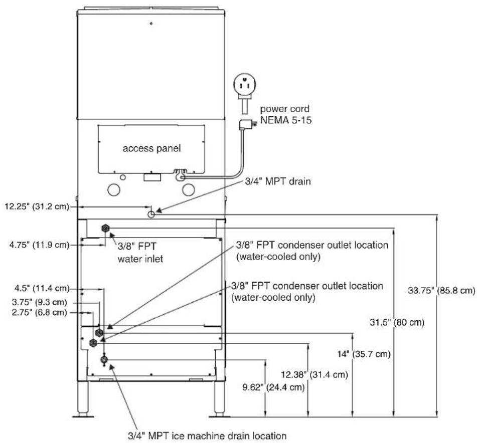
- Remove top front cover by removing two screws at bottom corners of cover. Lift cover slightly and pull forward.
- If dispenser is equipped with SensorSAFE remove protective plastic coating from dispense sensor labels.
- Turn on dispenser power and bin signal rocker switches. Check dispenser and ice machine operation.
- Sanitize ice machine according to instructions in ice machine manual. Discard ice made during sanitizing process.
- Turn off ice machine bin signal switch.
- Remove dispenser hopper lid; sanitize dispenser according to instructions beginning on page 12.
- Turn ice machine bin signal switch on and replace front covers, securing with screws.
Installing countertop dispensers

CAUTION!
Dispensers with top mount ice machines cannot be mounted on legs. They must be bolted to counter. Use gloves when lifting ice machine to protect hands from sheet metal edges.
- Position dispenser in desired location, mark dispenser outline on counter and remove dispenser.
- Regardless of whether utilities will exit through back or bottom of dispenser, drill four (4) 3/8" holes in counter to anchor dispenser to counter (Fig. 2).
Follett countertop dispensers can have any or all utilities run directly through counter or out rear of dispenser. For dispensers with any utilities exiting through counter, make counter cut-out (Fig. 2).
3. For utilities exiting through bottom only:
(a) Make cut out as shown in Fig. 2.
(b) Move drain fitting from back of dispenser and mount where shown in Fig. 3.
(c) Cut drain tube to length and attach to barbed connection.
(d) Move inlet water fitting from back of dispenser and mount where shown in Fig. 3.
(e) Cut water tubing to length and re-insert into water fitting.
- If ice transport tube will exit out rear of dispenser, remove ice transport tube knock-out from rear of dispenser. Install supplied grommet for CR models.
Note: Utility connections can be accessed through front of dispenser by removing stainless steel splash panel, or by removing access panel (Fig. 4) on back of dispenser.
Fig. 2
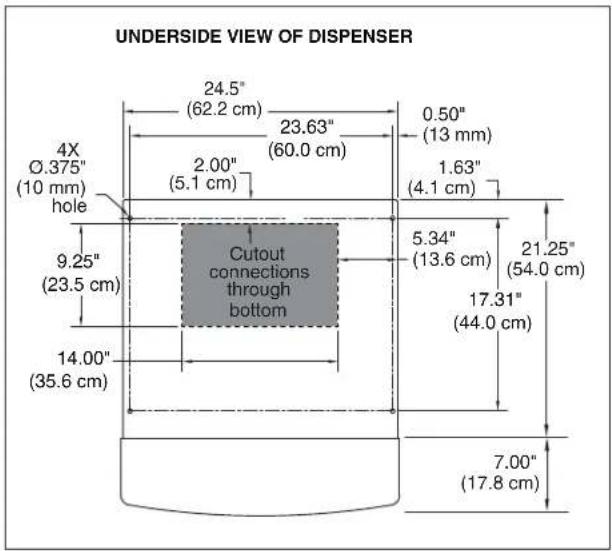
Fig. 3 – Bottom exiting utilities (countertop units)
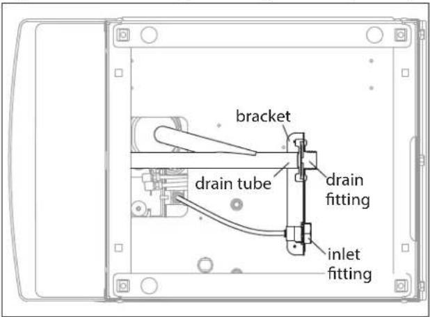
Fig. 4 – Rear connections, countertop models

- If power is to be supplied through counter cut-out, complete steps 6-9. If power is to be supplied through rear of dispenser, proceed to step 10.
- Temporarily remove rear access panel (Fig. 4) from rear of dispenser.
- Loosen junction box mounting screws. Lift junction box and power cord up until cord and mounting screws clear notches on rear panel of dispenser. Remove Phillips head screws from right side of junction box.
- Rotate junction box 90 degrees so that screw holes on right side of junction box align with holes on rear dispenser panel. Resecure junction box to dispenser using Phillips head screws.
- Place power cord inside dispenser and replace access panel (Fig. 4) to rear of dispenser.
Note: For dispensers to be installed with utilities connected through rear of dispenser, it may be easier to make preliminary connections before dispenser is set in place.
- Apply a thick bead, approximately. 1/4" (6 mm) diameter, of NSF listed silicone sealant (Dow-Corning* RTV-732 or equivalent) 1/4" (6 mm) inside marked outline of dispenser.
- Carefully position dispenser on counter.
- Remove four screws securing splash panel to front of dispenser and gently lay splash panel on counter. (Water line to solenoid valve can be disconnected from water inlet valve by pushing on ring at end of inlet fitting while pulling on tubing.)
- Secure dispenser to counter with four 3/8" bolts (supplied by others).
- Smooth excess sealant around outside of dispenser.
- Proceed with either RIDE or top-mounted ice machine connection instructions, as appropriate.
Installing RIDE ice machines

CAUTION!
See Ice Machine Installation Manual (form #01062587) for critical installation instructions for RIDE ice machines. Failure to comply with these instructions will result in poor performance and void warranty.
- Install RIDE ice machine following instructions in ice machine manual.
- If dispenser is equipped with SensorSAFE remove protective plastic coating from dispenser lenses.
- Remove top front cover by removing two screws at bottom corners of cover. Lift cover slightly and pull forward. Turn on power and bin signal rocker switches. Replace front cover and secure with screws. Test operation.
- Sanitize ice machine following instructions in ice machine manual. Discard ice made during sanitizing process.
- Sanitize dispenser hopper following instructions on page 12. Installation is complete.
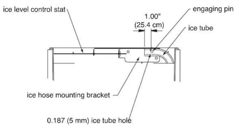
Fig. 5 – Ice transport tube and ice level control stat mounting for freestanding dispensers and countertop units with RIDE ice machine

CAUTION!
Dispensers with top mount ice machines cannot be mounted on legs. They must be bolted to counter. Use gloves when lifting ice machine to protect hands from sheet metal edges. See Ice Machine manual.
- Remove dispenser top front cover by removing two screws at bottom corners of cover, lifting cover slightly and pulling forward.
- Remove ice machine compartment top and side panels.
- Remove ice machine hold-down bracket from front of ice machine compartment.
- Lift ice machine onto dispenser top and slide ice machine completely into position, compressor end first.
- Reinstall hold-down bracket on front of ice machine with power cord and bin signal cords in notch. Do not cut or pinch cords.
- Insert loose end of ice transport tube through bracket (on ice machine base) into hopper access hole. Tighten transport tube clamp screw to secure ice transport tube.
- Connect plastic water supply line to water fill solenoid.

- Connect molded drain tube to evaporator drain pan, purge solenoid and rear drain fitting.

flowchart
graph TD
    A["Evaporator"] --> B["ICE NOZZLE"]
    B --> C["WATER RESERVOIR"]
    C --> D["RESERVOIR FILL SOLENOID"]
    D --> E["WATER SUPPLY 3/8" FPT, 45-90 F (7-32 C) 10-70 PSI (69-483 KPA)"]
    C --> F["DRAIN PAN"]
    F --> G["TO DRAIN CUP"]
    C --> H["DRAIN VALVE"]
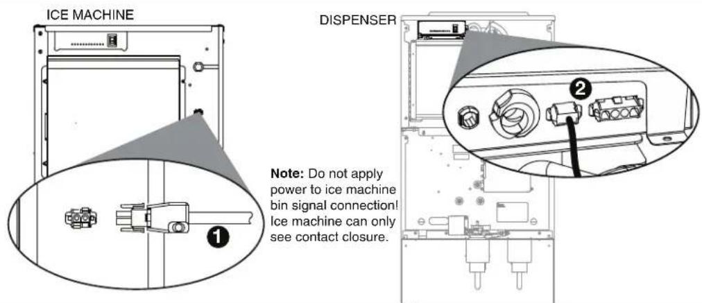
- Connect ice machine bin signal cable to two-pin receptacle on the dispenser electrical box.
- On dispensers equipped with water-cooled ice machines, connect condenser water supply and drain lines to condenser fittings on ice machine.
- Turn on water supply and check for leaks.
- Plug dispenser power cord into 15A rated NEMA 5-15 circuit.
- If dispenser is equipped with SensorSAFE, remove protective plastic coating from dispense sensor labels.
- Turn on power and bin signal rocker switches and test operation.
- Sanitize ice machine following instructions in ice machine manual.
- Remove dispenser hopper access lid and sanitize dispenser according to instructions on page 12.
- Replace front cover and secure with screws. Installation is complete.
User information
How the dispenser works
Follett's 110 series automatic-load ice and water dispensers are equipped with Follett's 425 lb (193 kg)/day ice machine. In the continuous icemaking process, water freezes to the inside wall of the evaporator. A rotating stainless steel auger carries the ice to the top of the evaporator where it is compressed and extruded through an outlet port. The ice is then pushed through a tube to the storage hopper. When the hopper is full, a bin thermostat opens and shuts the ice machine off. When the dispense mechanism is activated, a dispense motor is turned on, causing the wheel to turn. This moves ice to the dispense chute where it drops by gravity into the container held below the chute.
How SensorSAFE infrared dispensing works
Follett's SensorSAFE infrared dispensing maximizes sanitation and minimizes the possibility of cross-contamination by eliminating physical contact between the cup or container and dispenser. Sensors in the panel use reflected infrared light to detect the presence of the container and send a signal to a control board which then activates the appropriate components for ice or water dispensing.
The SensorSAFE infrared dispensing package includes a cleaning switch under the left side of the front cover which temporarily shuts off dispensing to allow cleaning of the panel and lenses. If the switch is not turned back on after cleaning, the dispenser automatically resets after two minutes for normal operation.
SensorSAFE infrared dispensing also includes a time limit safety feature which automatically stops ice dispensing after one minute of continuous dispensing. Dispensing can be resumed by moving the container away from the dispenser and returning it to the activation zone.
Quiet Night™/Sleep cycle (does not apply to CR units)
The board monitors ice dispensing through a line voltage input to P15. If the ice dispense has not been initiated for more than 5 seconds during the 20 minute time delay, the SLEEP CYCLE LED comes on. The machine will stay off for 12 hours unless 5 seconds of dispensing is seen. After 12 hours, the SLEEP CYCLE LED goes out and the ice making will resume if the bin thermostat is closed. The sleep cycle can be deated using the DIP switches on the ice machine control board.
Cleaning/descaling and sanitizing
Follett ice machines and dispensers, and their associated cleaning and sanitizing procedures, are designed for use with potable water sources. The presence, or suspected presence, of infectious agents may call for additional measures, including the replacement of components and more comprehensive disinfection measures. Follett recommends that these cleaning and sanitizing procedures be reviewed with the appropriate infectious agent subject matter experts to assure complete remediation.
Periodic cleaning/descaling and sanitizing of Follett's ice and water dispenser and ice machine system is required to ensure peak performance and delivery of clean, sanitary ice. The recommended cleaning procedures that follow should be performed at least as frequently as recommended and more often if environmental conditions dictate.
Cleaning of the condenser can usually be performed by facility personnel. Cleaning/descaling and sanitizing of the ice machine system should be performed by your facility's trained maintenance staff or a Follett authorized service agent. Regardless of who performs the cleaning, it is the operator's responsibility to see that this cleaning is performed according to the schedule below. Service problems resulting from lack of preventive maintenance will not be covered under the Follett warranty.
Recommended cleaning/descaling and sanitizing intervals*
| Symphony Plus Frequency | |
| Drain Line weekly | |
| Drain Pan/Drip Pan weekly | |
| Exterior as needed | |
| Condenser monthly (air-cooled only) | |
| Dispenser and Components semi-annually | |
| Ice Machine semi-annually | |
| Transport Tube semi-annually | |
| Ice Storage Area/Bin semi-annually |
* Ice machine and dispenser must be sanitized prior to start-up.
Weekly
CAUTION!
- Do not use solvents, abrasive cleaners, metal scrapers or sharp objects to clean any part of the dispenser.
Dispenser drain pan and drain line
- Pour 1 gal. (3.8 L) of hot tap water into drain pan to flush drains.
Splash panel front, SensorSAFE infrared dispensing
- Deactivate dispensing by pressing and releasing clean switch located on left side of unit under top front cover.
- Clean lens and splash panel front using a soft cloth and mild, non-abrasive, non-chlorine based cleaner.
- Reactivate dispensing by pressing and releasing clean switch again.
Monthly
CAUTION!
- Do not use solvents, abrasive cleaners, metal scrapers or sharp objects to clean any part of the dispenser.
Condenser (air-cooled ice machine only)
- Use a vacuum cleaner or stiff brush to carefully clean condenser coils of lint and debris to ensure optimal performance.
Semi-Annually (more often if conditions dictate)
- A cleaning/descaling and sanitizing procedure should always include both the ice machine and dispenser.
- Icemaking system can be cleaned/descaled in place.

CAUTION!
- Wear rubber gloves and safety goggles (or face shield) when handling cleaner or sanitizer mixtures.
■ Use only Follett approved cleaners. - It is a violation of Federal law to use Solution A or Solution B in a manner inconsistent with their labeling.
- Do not use solvents, abrasive cleaners, metal scrapers or sharp objects to clean any part of the dispenser.
Solution A: Following manufacturer's instructions, mix cleaning solution of 1 gal. (3.8 L) 120 F (49 C) water and 7 oz (198 g) (one 7 oz packet) of Follett SafeCLEAN™ ice machine cleaner/descaler (P/N 00132001).
Solution B: Following manufacturer's instructions, mix a sanitizing solution of 1 gal. (3.8 L) 120 F (49 C) water and 1.6 oz (48 ml) Nu-Calgon IMS-II Sanitizer (P/N 00979674).
Cleaning & Sanitizing Tool Checklist
■ (2) 1.5 Gallon (or larger) Plastic Buckets
(2) clean cloths
■ Sanitary gloves
Safety Glasses
■ (2) Sani-Sponge™ (P/N 00131524 - single sponge)
(1) Packet of SafeCLEAN™ (P/N 00132001 - 24 packets)
- 1.6 fl oz of Nu-Calgon IMS-II Sanitizer (P/N 00979674 - 16 fl. oz bottle)
Ice Machine and Dispenser
Cleaning/Descaling Procedure
Note: Check drains and drain cup to ensure they are open and flowing freely.
- Remove front cover and turn OFF bin signal switch.
- Dispense all ice from storage hopper and discard.
Note: CI Models only: remove splash panel. - Press CLEAN switch. The MAINTENANCE light will turn on and the machine will drain. Wait for the LOW WATER light to turn on.
- Remove lid from cleaning cup and fill (about 1 quart) until cleaning solution completely fills the reservoir. Place lid back on cup. Save remainder of cleaning solution.
-
CLEANER FULL light will turn on and machine will start cleaning cycle then rinse three times; this process takes approximately 15 minutes.
-
While ice machine is cleaning/descaling, clean dispenser as follows:
a. Turn OFF dispenser power.
b. Remove hopper lid. (Note: for CT models, remove hopper access cover)
c. Remove knurled nuts from front of storage hopper.
d. Remove stud assembly, baffle, wheel, and any remaining ice.
e. Remove dispense chutes from splash panel.
f. Submerse drain grill in cleaning solution and allow to soak to remove any scale buildup.
g. Wipe stud assembly, baffle, wheel, inside of storage area, dispense chutes, drain grill and drain pan with damp cloth wrung out in cleaning solution. Thoroughly rinse all parts with damp cloth wrung out with clean water.
Note: To avoid possible damage to motor assembly, only use a damp cloth to clean storage hopper. Do not allow water to run through motor shaft hole in bottom of hopper.
- When machine is finished cleaning, the MAINTENANCE light will turn off.
Sanitizing Procedure
- Press CLEAN switch. The MAINTENANCE light and LOW WATER light will turn on.
- Fill cleaning cup until sanitizing solution completely fills the reservoir. Place lid back on cup. Save remainder of sanitizing solution.
- CLEANER FULL light will turn on and machine will start sanitizing cycle then rinse three times; this process takes approximately 15 minutes.
- While ice machine is sanitizing, sanitize dispenser as follows:
a. Wipe inside of hopper lid, stud assembly, baffle, wheel, inside of storage area, dispense chutes, drain grill and drain pan with damp cloth wrung out in sanitizing solution.
Note: To avoid possible damage to motor assembly, only use a damp cloth to clean storage hopper. Do not allow water to run through motor shaft hole in bottom of hopper.
b. Reinstall dispense chutes, wheel, baffle, stud assembly and knurled nuts. (See manual for correct baffle position.)
-
When machine is finished rinsing, the MAINTENANCE light will turn off. Loosen phillips-head screw on nozzle connected to evaporator. Remove nozzle from evaporator side only, leave other side of nozzle connected to transport tube.
-
Place one Sani-Sponge in remaining sanitizing solution.
-
Insert the sponge soaked in sanitizing solution into nozzle then insert a dry sponge into the nozzle.
-
Replace nozzle onto evaporator and tighten screw. Ensure drain is connected to reservoir and vent tubes are connected to evaporator drain pan.
-
Turn ON bin signal switch. Wait for ice to push sponges through transport tube.
-
Collect sponges from ice storage bin.
-
Replace hopper lid (access cover for CT models), machine top, turn ON dispenser power and install front cover.
-
After 10 minutes, dispense all ice and discard.
Dispenser only
Cleaning/descaling procedure
Note: Check drains and drain cup to ensure they are open and flowing freely.
- Remove and discard all ice from storage hopper.
-
Ensure power is disconnected. Working inside storage area, remove center thumbscrew from dispense wheel, tilt wheel up toward back to clear baffle and disengage wheel from motor shaft.
-
Remove dispense chutes.
-
Thoroughly wipe lid, dispense wheel, baffle and dispense chutes with cloth soaked in Solution A.
-
Wipe all bin surfaces (including the area under dispense wheel) with a damp cloth wrung out in Solution A.
Note: To avoid possible damage to dispense motor assembly, use only a damp cloth to clean the storage bin. Do not allow water to run through bottom of bin area.
- Remove grille and wash with Solution A. Rinse thoroughly with clean water.
- Rinse all above items with damp cloth wrung out in clear water.
Sanitize dispenser
- Wipe all above items with damp cloth wrung out in Solution B to sanitize. Do not rinse.
- Reinstall all parts and replace any panels removed prior to cleaning.
- Pour 1 gal. (3.8 L) of hot tap water into drain pan to flush drains.
- If the dispenser is equipped with a Chilled Water Accessory continue to Step 11.1; if not, skip to Step 12.
11.1 Remove four screws securing splash panel.
11.2 Disconnect 3/4" (19 mm) drain line from bottom of chilled water canister.
11.3 Loosen (do not remove) screw securing front bracket of chilled water canister to bottom of dispenser hopper.
11.4 Rotate canister clockwise to release front bracket, then pull canister forward to disengage rear bracket.
11.5 Remove chilled water coil from canister and clean with cloth wrung out in Solution A.
11.6 Wipe inside of chilled water canister with cloth wrung out in Solution A.
11.7 Rinse all above items with damp cloth wrung out in clear water.
11.8 Sanitize all above items with damp cloth wrung out in Solution B. Do not rinse.
11.9 Reinstall chilled water coil into canister (rubber alignment grommet on coil tubing must be located outside chilled water canister to hold coil securely against canister wall).
11.10 Reinstall chilled water assembly on dispenser and tighten screw securing front bracket.
11.11 Reconnect 3/4" (19 mm) drain line to chilled water canister.
11.12 Reinstall splash panel and top front cover.
-
If so equipped, turn ice machine ON and begin to make ice (ice machine should start immediately with power and bin signal supplied).
-
After approximately 30 minutes, test dispenser for proper dispensing.
This page intentionally left blank.
Service
Wiring diagram
Lever models
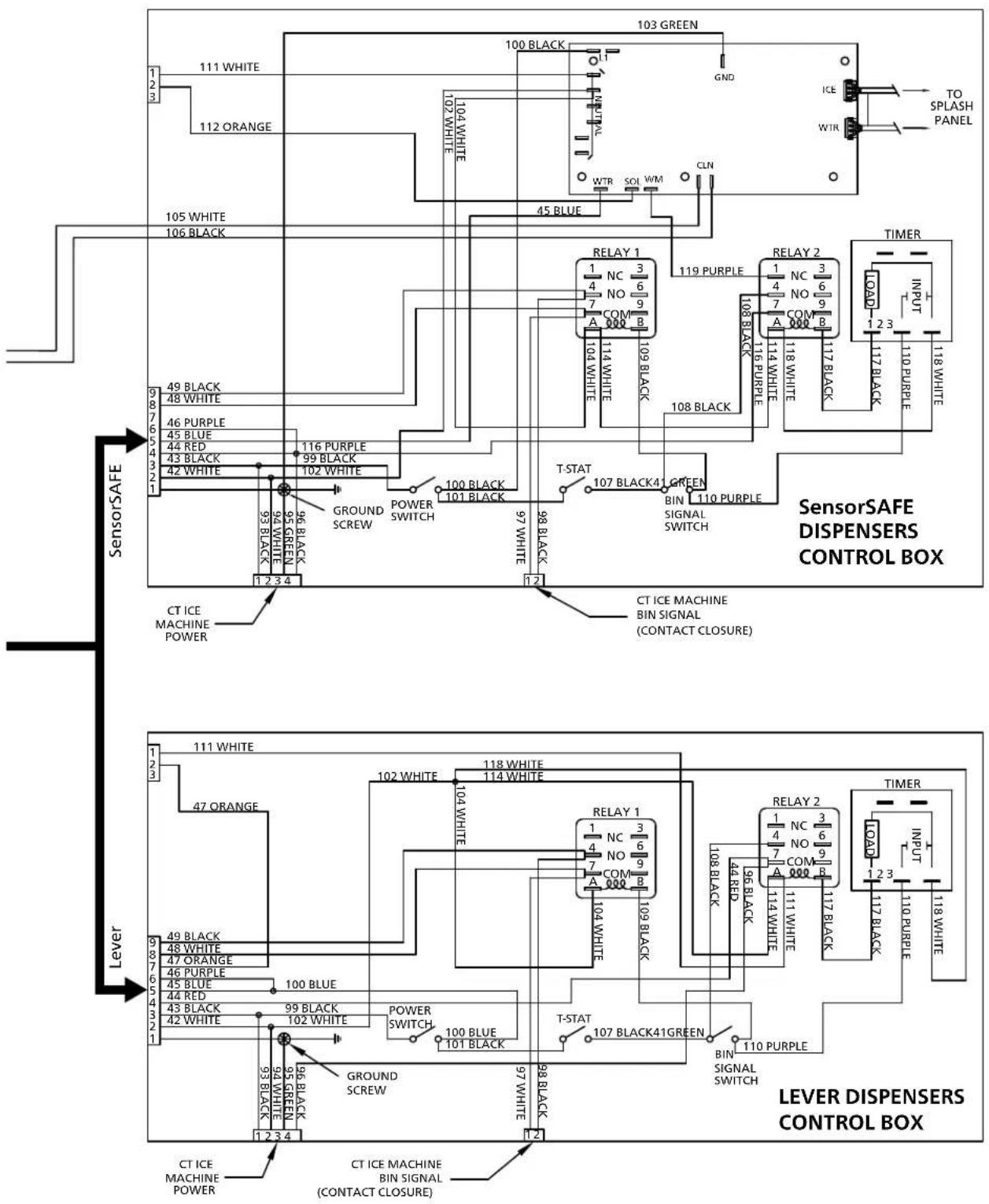
The dispense wheelmotor is energized through the power and ice dispense switches. The water solenoid valve is energized through the power and water dispense switches. The ice machine is controlled through an unpowered contact closure bin thermostat circuit. When ice builds up around the bin thermostat, the contacts open, cutting the bin signal to the ice machine.
SensorSAFE models
SensorSAFE models provide "touchless" ice and water dispensing. When a container is placed within the actuation zone below the ice or water chute on SensorSAFE dispenser models, an infrared signal reflects off the container and is detected by the sensor. The sensor then sends a signal to the control board to activate the appropriate components to dispense ice or water. LEDs on the board indicate when the board is receiving a signal from the sensors.

flowchart
graph TD
    A["SensorSAFE DISPENSERS SPLASH PANEL"] --> B["ICE SENSOR"]
    A --> C["WATER SENSOR"]
    B --> D["TO BOX"]
    C --> E["BOX"]
    D --> F["83 PURPLE 82 BLUE 81 WHITE"]
    E --> G["87 WHITE"]
    F --> H["S"]
    G --> I["S"]
    H --> J["LEVER DISPENSERS SPLASH PANEL"]
    I --> K["LEVER"]
    J --> L["ICE STATION SWITCH"]
    K --> M["90 PURPLE 85 ORANGE 84 RED 83 PURPLE 82 BLUE 81 WHITE"]
    L --> N["89 PURPLE 88 BLUE 87 WHITE"]
    M --> O["WATER STATION SWITCH"]
    N --> P["WATER SOLENOID"]
    O --> Q["S"]
    P --> R["S"]
    S["FLB/CR ICE MACHINE BIN SIGNAL (CONTACT CLOSURE)"] --> T["FB/CR ICE MACHINE POWER"]
    T --> U["12 34 75 BLACK 74 GREEN 73 BLACK 72 BLACK 71 BLACK 70 BLACK 69 BLACK 68 BLACK 67 BLACK 66 BLACK 65 BLACK 64 BLACK 63 BLACK 62 BLACK 61 BLACK 60 BLACK 59 BLACK 58 BLACK 57 BLACK 56 Black 55 Black 54 Black 53 Black 52 Black 51 Black"]
    U --> V["4x4 POWER BOX"]
    V --> W["115/1/60-BLACK NEUTRAL-WHITE GROUND-GREEN"]
    W --> X["GROUND SCREW"]
    X --> Y["S"]
    Y --> Z["WHITE ORANGE"]
    Z --> AA["1-ND"]
DISPENSE GATE SOLENOID
A safety, shut-off feature automatically shuts off dispensing after one minute of continuous activation.
Dispensing can be restarted by moving the container away and then returning it to the actuation zone.
Dispensing can be temporarily suspended for cleaning by depressing and releasing the clean switch, located under the left side of the top front cover. Depressing and releasing the button a second time will return the dispenser to normal operating state. If the clean switch is not depressed a second time, the dispenser will automatically resume normal dispense operation (CLN LED goes out) after two minutes. An LED on the control board will light to indicate that the dispensing has been suspended by activation of the clean switch.
flowchart
graph TD
    subgraph SensorSAFE
        A["111 WHITE"] --> B["103 GREEN"]
        C["112 ORANGE"] --> D["100 BLACK"]
        E["105 WHITE"] --> F["45 BLUE"]
        G["106 BLACK"] --> H["109 BLACK"]
        I["49 BLACK"] --> J["119 PURPLE"]
        K["48 WHITE"] --> L["108 BLACK"]
        M["46 PURPLE"] --> N["117 BLACK"]
        O["45 BLUE"] --> P["118 WHITE"]
        Q["44 RED"] --> R["117 BLACK"]
        S["43 BLACK"] --> T["118 PURPLE"]
        U["42 WHITE"] --> V["110 PURPLE"]
        W["96 BLACK"] --> X["98 BLACK"]
        Y["95 GREEN"] --> Z["POWER SWITCH"]
        AA["93 BLACK"] --> AB["Ground SCREW"]
        AC["92 WHITE"] --> AD["POWERS SWITCH"]
        AE["91 BLACK"] --> AF["POWER SWITCH"]
        AG["90 GREEN"] --> AH["GROUND SCREW"]
        AI["100 BLACK"] --> AJ["107 BLACK4"]
        AK["101 BLACK"] --> AL["GREEN BIN SIGNAL SWITCH"]
        AM["100 BLACK"] --> AN["T-STAT 107 BLACK4"]
        AO["97 WHITE"] --> AP["98 BLACK"]
    end

    subgraph Lever
        AQ["111 WHITE"] --> AR["102 WHITE"]
        AS["47 ORANGE"] --> AT["104 WHITE"]
        AU["49 BLACK"] --> AV["102 BLUE"]
        AW["48 WHITE"] --> AX["100 BLUE"]
        AY["47 ORANGE"] --> AZ["102 BLUE"]
        BA["46 PURPLE"] --> BB["POWER SWITCH"]
        BC["45 BLUE"] --> BD["100 BLUE"]
        BE["44 RED"] --> BF["99 BLACK"]
        BG["43 BLACK"] --> BH["98 BLACK"]
        BI["42 WHITE"] --> BJ["GROUND SCREW"]
        BK["93 BLACK"] --> BL["GROUND SCREW"]
        BM["92 GREEN"] --> BN["GROUND SCREW"]
    end

    subgraph SensorSAFE DISPENSERS
        BO["SensorSAFE DISPENSERS CONTROL BOX"]
    end

    subgraph Lever
        BP["SensorSAFE DISPENSERS CONTROL BOX"]
    end

    A -->|SensorSAFE| B
    A -->|SensorSAFE| C
    A -->|SensorSAFE| D
    A -->|SensorSAFE| E
    A -->|SensorSAFE| F
    A -->|SensorSAFE| G
    A -->|SensorSAFE| H
    A -->|SensorSAFE| I
    A -->|SensorSAFE| J
    A -->|SensorSAFE| K
    A -->|SensorSAFE| L
    A -->|SensorSAFE| M
    A -->|SensorSAFE| N
    A -->|SensorSAFE| O
    A -->|SensorSAFE| P
    A -->|SensorSAFE| Q
    A -->|SensorSAFE| R
    A -->|SensorSAFE| S
    A -->|SensorSAFE| T
    A -->|SensorSAFE| U
    A -->|SensorSAFE| V
    A -->|SensorSAFE| W
    A -->|SensorSAFE| X
    A -->|SensorSAFE| Y
    A -->|SensorSAFE| Z
    A -->|SensorSAFE| AA
    A -->|SensorSAFE| AB
    A -->|SensorSAFE| AC
    A -->|SensorSAFE| AD
    A -->|SensorSAFE| AE
    A -->|SensorSAFE| AF
    A -->|SensorSAFE| AG
    A -->|SensorSAFE| AH
    A -->|SensorSAFE| AI
    A -->|SensorSAFE| AJ
    A -->|SensorSAFE| AK
    A -->|SensorSAFE| AL
    A -->|SensorSAFE| AM
    A -->|SensorSAFE| AN
    A -->|SensorSAFE| AO
    A -->|SensorSAFE| AP
    A -->|SensorSAFE| AQ
    A -->|SensorSAFE| AR
    A -->|SensorSAFE| AS
    A -->|SensorSAFE| AT
    A -->|SensorSAFE| AU
    A -->|SensorSAFE| AV
    A -->|SensorSAFE| AW
    A -->|SensorSAFE| AX
    A -->|SensorSAFE| AY
    A -->|SensorSAFE| AZ
    A -->|SensorSAFE| BA
    A -->|SensorSAFE| BB
    A -->|SensorSAFE| BC
    A -->|SensorSAFE| BD
    A -->|SensorSAFE| BE
    A -->|SensorSAFE| BF
    A -->|SensorSAFE| BG
    A -->|SensorSAFE| BH
    A -->|SensorSAFE| BI
    A -->|SensorSAFE| BJ
    A -->|SensorSAFE| BK
    A -->|SensorSAFE| BL
    A -->|SensorSAFE| BM
    A -->|SensorSAFE| BN
    A -->|SensorSAFE| BO
    A -->|SensorSAFE| BP
    A -->|SensorSAFE| BPB
    A -->|SensorSAFE| BPC
    A -->|SensorSAFE | BPD
    B --> B1["RELAY 1 NC 3 NO 6 COM 9 COM 8 COM 8 COM 8 COM 8 COM 8 COM 8 COM 8 COM 8 COM 8 COM 8 COM 8 COM 8 COM 8 COM 8 COM 8 COM 8 COM 8 COM 8 COM 8 COM 8 COM 8 COM 8 COM 8 COM 8 COM 8 COM 8 COM 8 COM 8 COM 8 COM 8 COM 8 COM 8 COM 8 COM 8 Com 8 COM 8 COM 8 COM 8 COM 8 COM 8 COM 8 COM 8 COM 8 COM 8 COM 8 Com 8 Com 8 Com 8 Com 8 Com 8 Com 8 Com 8 Com 8 Com 8 Com 8 Com 8 Com 8 Com 8 Com 8 Com 8 Com 8 Com 8 Com 8 Com 8 Com 8 Com 8 Com 8 Com 8 Com 8 Com 8 Com 8 Com 8 Com 8 Com 8 Com 8 Com 8 Com 8 Com 8 Com/INTERPUMBERS"]
    B --> B2["RELAY 2 NC 3 NO 6 COM 9 COM 8 COM 8 COM 8 COM 8 COM 8 COM 8 COM 8 COM 8 COM 8 COM 8 COM 8 COM 8 COM 8 COM 8 COM 8 COM 8 COM 8 COM 8 COM 8 COM 8 COM 8 COM 8 COM 8 COM 8 COM 8 COM 8 COM 8 COM 8 COM 8 COM 8 Com/INTERPUMBERS"]
    B --> B3["Timer INPUT LOAD"]
    B --> B4["LOAD INPUT LOAD"]

    subgraph SensorSafe Dispensers
        B1["SensorSafe Dispensers CONTROL BOX"]
        B2["Lever Dispensers CONTROL BOX"]
        B3["Lever Dispensers CONTROL BOX"]
        B4["Lever Dispensers CONTROL BOX"]
        B5["Lever Dispensers CONTROL BOX"]
        B6["Lever Dispensers CONTROL BOX"]
        B7["Lever Dispensers CONTROL BOX"]
        B8["Lever Dispensers CONTROL BOX"]
        B9["Lever Dispensers CONTROL BOX"]
        B10["Lever Dispensers CONTROL BOX"]
        B11["Lever Dispensers CONTROL BOX"]
        B12["Lever Dispensers CONTROL BOX"]
        B13["Lever Dispensers CONTROL BOX"]
        B14["Lever Dispensers CONTROL BOX"]
        B15["Lever Dispensers CONTROL BOX"]
        B16["Lever Dispensers CONTROL BOX"]
        B17["Lever Dispensers CONTROL BOX"]
        B18["Lever Dispensers CONTROL BOX"]
        B19["Lever Dispensers CONTROL BOX"]
        B20["Lever Dispensers CONTROL BOX"]
        B21["Lever Dispensers CONTROL BOX"]
        B22["Lever Dispensers CONTROL BOX"]
        B23["Lever Dispensers CONTROL BOX"]
        B24["Lever Dispensers CONTROL BOX"]
        B25["Lever Dispensers CONTROL BOX"]
        B26["Lever Dispensers CONTROL BOX"]
        B27["Lever Dispensers CONTROL BOX"]
        B28["Lever Dispensers CONTROL BOX"]
        B29["Lever Dispensers CONTROL BOX"]
        B30["Lever Dispensers CONTROL BOX"]
        B31["Lever Dispensers CONTROL BOX"]
        B32["Lever Dispensers CONTROL BOX"]
        B33["Lever Dispensers CONTROL BOX"]
        B34["Lever Dispensers CONTROL BOX"]
        B35["Lever Dispensers CONTROL BOX"]
        B36["Lever Dispensers CONTROL BOX"]
        B37["Lever Dispensers CONTROL BOX"]
        B38["Lever Dispensers CONTROL BOX"]
        B39["Lever Dispensers CONTROL BOX"]
        B40["Lever Dispensers CONTROL BOX"]
        B41["Lever Dispensers CONTROL BOX"]
        B42["Lever Dispensers CONTROL BOX"]
        B43["Lever Dispensers CONTROL BOX"]
        B44["Lever Dispensers CONTROL BOX"]
        B45["Lever Dispensers CONTROL BOX"]
        B46["Lever Dispensers CONTROL BOX"]
        B47["Lever Dispensers CONTROL BOX"]
        B48["Lever Dispensers CONTROL BOX"]
        B49["Lever Dispensers CONTROL BOX"]
        B50["Lever Dispensers CONTROL BOX"]
        B51["Lever Dispensers CONTROL BOX"]
        B52["Lever Dispensers CONTROL BOX"]
        B53["Lever Dispensers CONTROL BOX"]
        B54["Lever Dispensers CONTROL BOX"]
        B55["Lever Dispensers CONTROL BOX"]
        B56["Lever Dispensers CONTROL BOX"]
        B57["Lever Dispensers CONTROL BOX"]
        B58["Lever Dispensers CONTROL BOX"]
        B59["Lever Dispensers CONTROL BOX"]
        B60["Lever Dispensers CONTROL BOX"]
        B61["Lever Dispensers CONTROL BOX"]
        B62["Lever Dispensers CONTROL BOX"]
        B63["Lever Dispensers CONTROL BOX"]
        B64["Lever Dispensers CONTROL BOX"]
        B65["Lever Dispensers CONTROL BOX"]
        B66["Lever Dispensers CONTROL BOX"]
        B67["Lever Dispensers CONTROL BOX"]
        B68["Lever Dispensers CONTROL BOX"]
        B69["Lever Dispensers CONTROL BOX"]
        B70["Lever Dispensers CONTROL BOX"]
        B71["Lever Dispensers CONTROL BOX"]
        B72["Lever Dispensers CONTROL BOX"]
        B73["Lever Dispensers CONTROL BOX"]
        B74["Lever Dispensers CONTROL BOX"]
        B75["Lever Dispensers CONTROL BOX"]
        B76["Lever Dispensers CONTROL BOX"]
        B77["Lever Dispensers CONTROL BOX"]
        B78["Lever Dispensers CONTROL BOX"]
        B79["Lever Dispensers CONTROL BOX"]
        B80["Lever Dispensers CONTROL BOX"]
        B81["Lever Dispensers CONTROL BOX"]
        B82["Lever Dispensers CONTROL BOX"]
        B83["Lever Dispensers CONTROL BOX"]
        B84["Lever Dispensers CONTROL BOX"]
        B85["Lever Dispensers CONTROL BOX"]
        B86["Lever Dispensers CONTROL BOX"]
        B87["Lever Dispensers CONTROL BOX"]
        B88["Lever Dispensers CONTROL BOX"]
        B89["Lever Dispensers CONTROL BOX"]
        B90["Lever Dispensers CONTROL BOX"]
        B91["Lever Dispensers CONTROL BOX"]
        B92["Lever Dispensers CONTROL BOX"]
        B93["Lever Dispensers CONTROL BOX"]
        B94["Lever Dispensers CONTROL BOX"]
        B95["Lever Dispensers CONTROL BOX"]
        B96["Lever Dispensers CONTROL BOX"]
        B97["Lever Dispensers CONTROL BOX"]
        B98["Lever Dispensers CONTROL BOX"]
        B99["Lever Dispensers CONTROL BOX"]

CAUTION!
- Disconnect power to unit before putting hands or arms in storage area or attempting any repair or service to equipment.
Before calling for service
- Check that no ice is in the dispenser bin area.
- Check that congealed ice is not causing a jam.
- Check that all switches and circuit breakers are on.
- Check that all drains are clear.
Lever model troubleshooting guide
| Problem Indicators | Corrective Action | |
| Does not dispense ice. 1. Power | switch off or faulty.2. Faulty dispense switch.3. Wheelmotor malfunction. | 1. Check switch – turn on or replace if faulty.2. Replace switch.3. Check motor and capacitor and replace. |
| Does not dispense water. 1. Dispense switch contacts burned shut.2. Debris preventing valve from closing. | 1. Replace water solenoid valve.2. Replace dispense switch.3. Check switch - turn on or replace if faulty. | |
| Water runs continuously. | 1. Faulty water solenoid valve.2. Faulty dispense switch.3. Power switch off or faulty. | 1. Check switch and replace if faulty.2 Remove and clean valve. |
| Dispense wheel rotates continuously. | Dispense switch contacts are burned out. | Replace dispense switch. |
| Ice machine runs continuously. | Faulty or incorrectly positioned bin stat. | Check for proper positioning. If stat does not open when ice is placed on capillary tube, replace stat. |
| Ice dispenses by itself. | 1. Baffle not adjusted properly.2. Faulty dispense switch. | 1. See Adjustment Instructions.2. Replace dispense switch. |
| Not making ice. | 1. Dispenser is in sleep mode. | 1. Verify sleep mode LED is illuminated on control board.2. Dispense 5 seconds worth of ice to reset. |
SensorSAFE model troubleshooting guide
| Problem Action | SensorSAFE Board LED Status | Corrective ActionPWR CLN | |||
| ICE/WTR | |||||
| Does not dispense ice and/or water. | Check LEDs on the SensorSAFE control board. | OFF OFF OFF Check circuit breakers and power switch.Restore power or replace defective switch. | |||
| ON ON OFF Press clean switch on lower left side of electrical enclosure to return board to normal operation. | |||||
| Place cup under drop zone (in front of lens). | ON OFF OFF Troubleshoot appropriate lens/sensor and replace if required (see lens/sensor troubleshooting). | ||||
| ON OFF ON Verify power on appropriate output terminal (WTR or WM) on control board and replace board if required. If board tests okay, troubleshoot appropriate dispenser component. | |||||
| Dispenses ice and/or water continuously. | Check LEDs on control board. | ON OFF ON Troubleshoot appropriate lens/sensor and replace if required (see lens/sensor troubleshooting). | |||
| ON OFF OFF If there is power on any output terminal 9 (WTR or WM) on control board, replace board. | |||||
Board guide
LEDs, when illuminated, indicate the following: PWR (board power), CLN (cleaning, no dispensing cycle), ICE (ice dispensing activated), WTR (water dispensing activated).
Terminals: LI (incoming power, hot), L2 (neutral terminals), WTR (power terminal for water solenoid), WM (power terminal for wheelmotor), CLN (terminals for clean cycle switch).
Note: SOL terminal not used in 12 series dispensers.
Lens/sensor troubleshooting
- Turn dispenser power switch off and remove splash panel.
- Disconnect wires from WTR and WM terminals on board.
- Gently remove sensor/mounting block from splash panel.
- Inspect lens and sensor, clean if necessary.
- Restore dispenser power and test sensor by passing hand in front of sensor.
- If LED on board turns on, sensor is operational. Re-assemble dispenser.
- If LED does not come on switch sensor leads on board and retest.
- If opposite LED comes on – replace defective board.
- If opposite LED does not come on – replace defective sensor.
Dispense chute removal
- Remove dispenser front cover.
- Slide plastic dispense chute up and out to remove.
Dispense wheel and drive bar removal
- Remove all ice from storage area of dispenser.
- Remove center thumbnut from dispense wheel.
- Remove thumbnails holding baffle inside bin and remove baffle.
- Tilt rear of wheel up and lift off motor drive shaft.
- After reinstalling wheel, secure baffle loosely with thumbnails, but do not tighten.
- Place a 1/8" (3.2 mm) spacer against wheel and allow baffle to drop until it touches spacer.
- Tighten thumbnails and remove spacer.
Drive bar removal
- Remove dispense wheel from dispenser (see above).
- Pull drive bar out of its channel in bottom of wheel.
Wheelmotor removal
- Shut water off. Remove front cover.
- Remove dispense wheel and dispense chute covers (see above).
- Remove splash panel. Water line to solenoid valve can be disconnected from water inlet valve by pulling on ring at end of inlet fitting.
- Disconnect wiring to panel and set panel aside.
- Disconnect wires on motor.
- Remove four bolts (7/16" socket) holding motor assembly to bottom of dispenser.
- Remove motor assembly.
Fig. 6

Ice transport tube replacement – Top mount units
Models 110CT425A/W
CAUTION!
■ Use only tubing supplied by Follett Corporation.

Ice transport tube replacement – Freestanding and RIDE models
- Correct installation of ice transport tube is critical to RIDE ice machine performance. Replacement ice transport tubes for RIDE ice machines must be insulated and run continuously from ice machine to dispenser with no dips or bends with a radius of less than 6" (15.3 cm).
- Remove top and rear access panel from dispenser (lower front panel in freestanding unit).
- Disconnect existing ice tube from engaging pin on transport tube bracket in ice storage bin and pull down through dispenser chase.
- Disconnect opposite end of tube from ice machine.
- Run end of new ice transport tube with 3/16" (5 mm) hole through ice transport tube knockout in back of dispenser or through counter into bottom of dispenser, being careful to avoid any bends with less than 6" (15.3 cm) radius.
- Insert tube in internal chase in rear inside corner of dispenser (left side as you face dispenser) and push up into storage area.
- Push the 3/16" (5 mm) hole near end of tube into pin on ice tube bracket (Fig. 8).
Fig. 7

Steps 7-8 for units with RIDE ice machines only
- Install supplied insulation to run of transport tube required for your site, leaving approximately 2" (5.1 cm) of tube exposed at free end.
- Check that insulated tube runs continuously from ice machine to dispenser with no dips.
- Heat end of transport tube in cup of 160 F (71 C) hot water to soften and spread with pliers before making connection to ease assembly and prevent coupler edge from cutting inner wall of tube (Fig. 8).
Fig. 8

All units
- Slip supplied hose clamp onto tube and push tube onto exit port of evaporator. Do not twist hose when securing to evaporator.
Note: Only use tubing supplied by Follett Corporation.
- Fasten tube on port with hose clamp, ensure that clamp is positioned on evaporator side of nozzle flange.
- Tighten clamp.
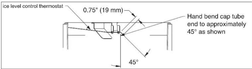
Thermostat replacement

Thermostat: hand bend cap tube end as shown

Dispenser exterior

| Reference | Description Part # | |
| 1 Cover, top | front, CT, ice and water 01072818 | |
| 2 Cover, top | front, CR/FB, ice and water 01072792 | |
| 3 Cover, lower section, FB 502704 | ||
| 4 Cover, dispense chute 502681 | ||
| Not shown Knurled screws, front cover 501100 | ||
| 5 Drain pan | 502705 | |
| Not shown Grille, drain pan 502706 | ||
| 6 Lid, ice machine, 110, countertop (CT) | 502709 | |
| 7 | Lid, 110, countertop (CR) units with RIDE ice machines & freestanding (FB) units | 01072784 |
| Not shown Leg kit, for freestanding units – set of 4 | 502088 | |
| 8 Single leg, for freestanding units | 502298 | |
| Not shown Drain tube assembly | 502711 | |
| Not shown Cover, top front, CT, ice only | 01072826 | |
| Not shown Cover, top front, CR/FB, ice only | 01072800 | |
| Not shown Tee, water inlet, 1/4" | 502923 | |
| Not shown Valve, water shut-off, 1/4" | 01035526 | |
| Not shown Drain fitting, plastic, ice machine (includes screws) | 00109728 | |
| Not shown Cord, power, dispenser, CR/CT/FB | 01027648 | |
| Not shown Cord & plug, bin signal, RIDE ice machine, 20' | 01074202 | |
| Not shown Cord & plug, bin signal, top mount and freestanding | 01074210 | |
| Not shown Clean switch, SensorSAFE | 502359 | |
| Not shown Cord & plug, female, ice machine power, freestanding (junction box to ice machine box) | 01074848 | |
| Not shown Caster | 502805 | |
Wheelmotor and drive system


| Reference Description | Part # | |
| 1 Wheelmotor, 120 V, | 60 Hz 501861 | |
| 2 Washer, thrust 501026 | ||
| Not shown Fan blade, | wheelmotor 501607 | |
| 3 Drive shaft (includes | key and stud) 501619 | |
| 4 Chain, pitch 54, link | 502691 | |
| 5 Sprocket, drive shaft | 35T 502692 | |
| 6 Sprocket, wheelmotor, | 10T 501019 | |
| 7 Bearing, drive shaft | 501024 | |
| Not shown Connecting | link, chain | 500799 |
| 8 Key, drive shaft | 500637 | |
| Parts 1-8 above | Dispenser drive assembly | 502020 |
Dispense chute and splash panel (models with lever dispensing)
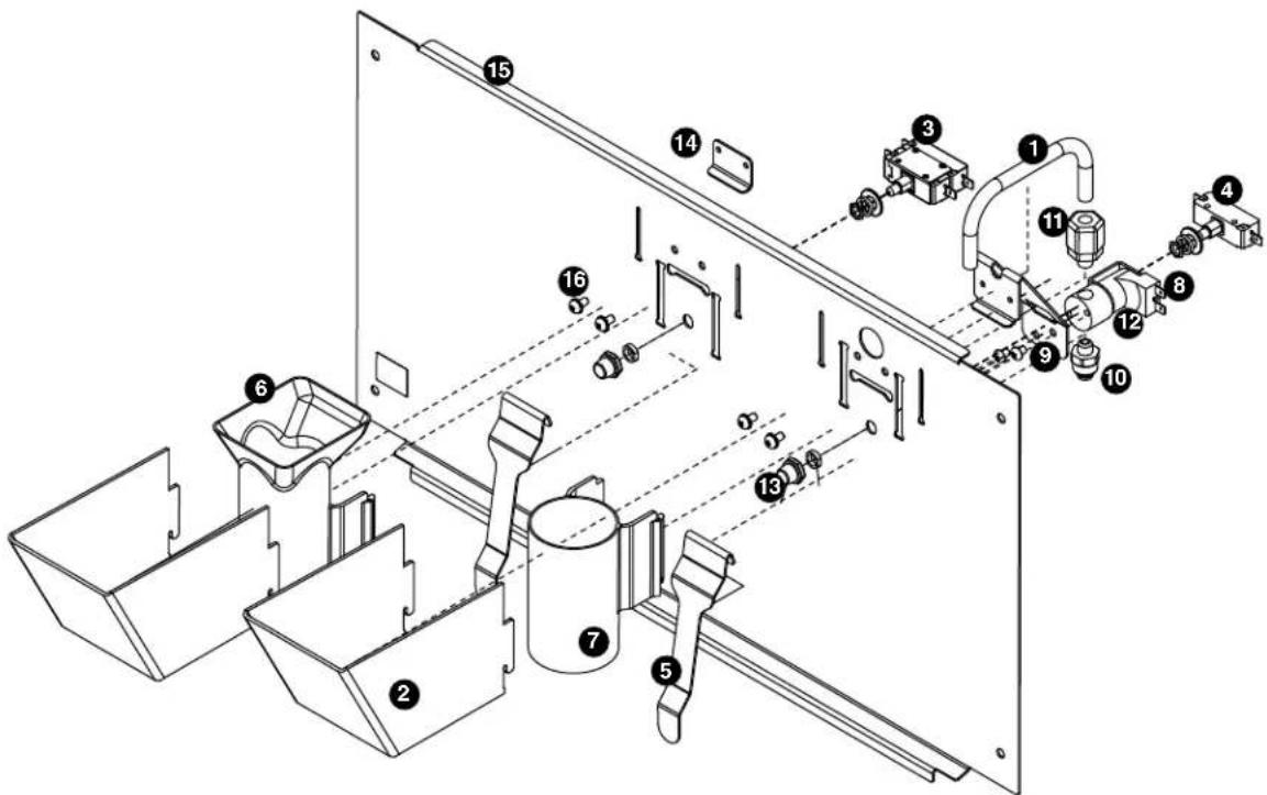
| Reference Description Part # | ||
| 1 Tube, water station 502356 | ||
| 2 Cover, dispense chute 502681 | ||
| 3 Switch, dispense, ice, lever actuated (includes 501841) 501829 | ||
| 4 Switch, dispense, water, lever actuated (includes 501841) 502359 | ||
| 5 Lever, dispense 00976845 | ||
| 6 Chute, ice (with Agion® antimicrobial product protection1) 01042787 | ||
| 7 Chute, water (with Agion) 01042795 | ||
| 8 Solenoid assembly, water, 120V, 60Hz (includes solenoid valve, tube, bracket, inlet and outlet fittings) | 01049121 | |
| 9 Bracket, lever and water solenoid 01039635 | ||
| 10 | Fitting, inlet, 1/4" tube x 1/8 MNPT straight | 00991232 |
| 11 | Fitting, outlet, 1/8" MPT x 3/8" comp | 502246 |
| 12 | Solenoid valve, water, 120 V, 60Hz | 502243 |
| 13 | Boot, dispense switch button | 501841 |
| 14 | Bracket, lever | 00958793 |
| 15 | Splash panel, lever dispense | 01039742 |
| 16 | Fastener, 10-32 x 3/8" stainless steel | 00982421 |
| Not shown | Tubing, water station, thermoplastic, 1/4" OD (sold by the foot) | 502079 |
| Not shown | Splash panel, lever dispense complete assembly | 01049055 |
| Not shown | Splash panel, lever dispense, ice only, complete assembly | 01049063 |
1 Disclaimer: Antimicrobial protection is limited to the treated components and does not treat water or ice. Agion is a registered trademark of Sciessent LLC.
Dispense chute and splash panel (models with SensorSAFE infrared dispensing)

| Reference Description Part # | ||
| 1 Cover, dispense | se chute 502681 | |
| 2 Chute, ice (with Agion® antimicrobial product protection1) 01042787 | ||
| 3 Chute, water (with Agion) 01042795 | ||
| 4 Lens, sensor | 502690 | |
| 5 Splash panel (includes 2 of 502690) 01049162 | ||
| Not shown Splash panel, SensorSAFE, ice only (includes 2 of 502690) 01049170 | ||
| 6 Solenoid assembly, water, 120V, 60Hz (includes solenoid valve, tube, bracket, inlet and outlet fittings) 120V 60Hz | 01049121 | |
| 7 Bracket, lever and water solenoid | 01039635 | |
| 8 Tube, water station | 502356 | |
| 9 Fitting, inlet, 1/4" tube x 1/8 MNPT straight | 00991232 | |
| 10 | Fitting, outlet, 1/8" MPT x 3/8" comp | 502246 |
| 11 | Solenoid valve, water, 120V, 60Hz | 502243 |
| 12 | Sensor (includes lens and ty-rap) | 00122978 |
| 13 | Fastener, 10-32 x 3/8" stainless steel | 00982421 |
| Not shown Splash panel, SensorSAFE, complete assembly | 01049030 | |
| Not shown Splash panel, SensorSAFE, ice only, complete assembly | 01049048 | |
1 Disclaimer: Antimicrobial protection is limited to the treated components and does not treat water or ice. Agion is a registered trademark of Sciessent LLC.
Electrical components


| Reference Description Part # | ||
| 1 Thermostat, bin level 500514 | ||
| 2 Switch, dispenser power 502209 | ||
| 2 Switch, ice machine bin signal 502209 | ||
| 3 Control board, SensorSAFE 502242 | ||
| Not shown Clean switch, SensorSAFE 502359 | ||
| Not shown Boot, clean switch 501841 | ||
| 4 | Relay, bin signal contact closure and level fill 501369 | |
| 5 | Timer, level fill 501601 | |
Hopper components
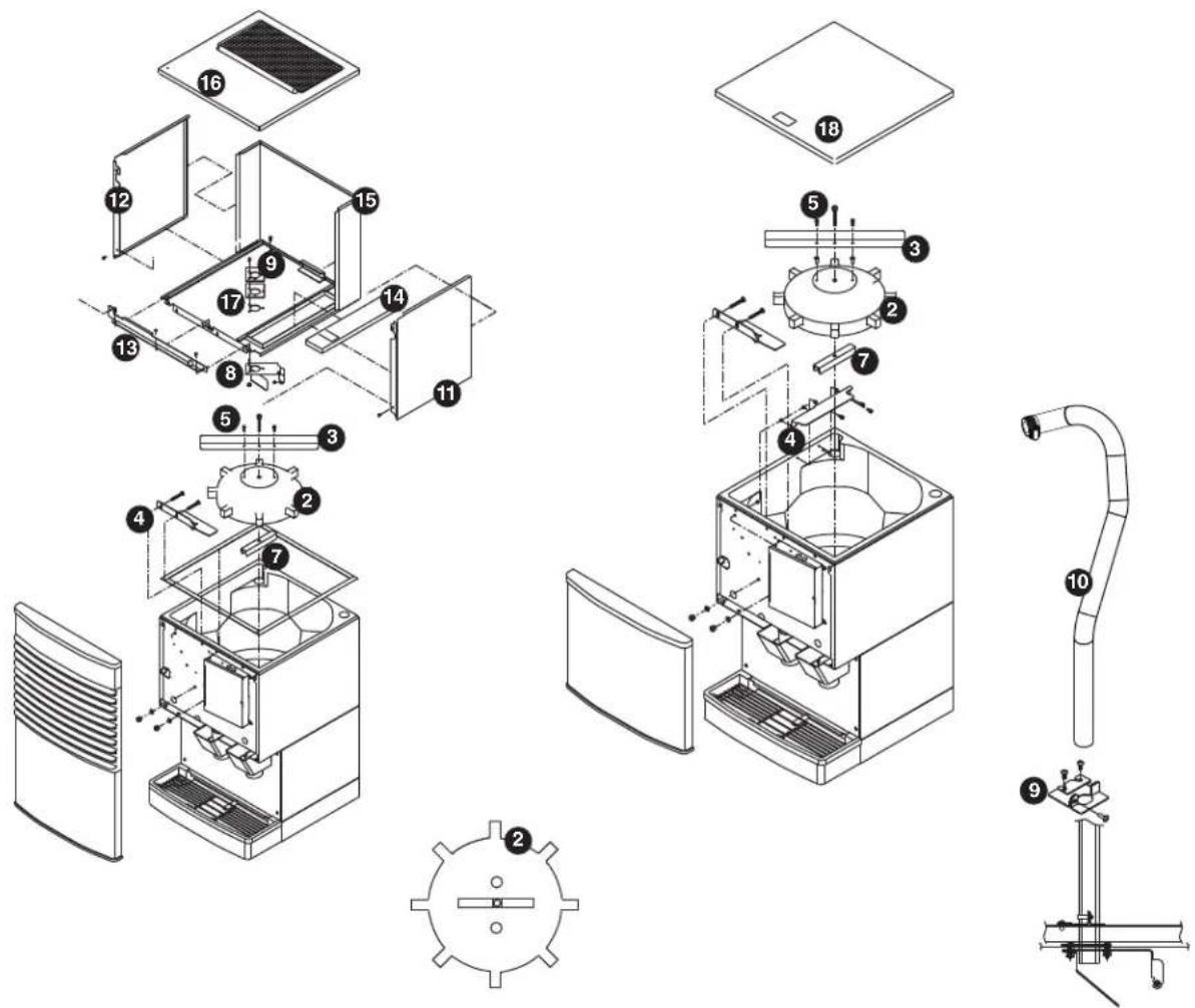
| Reference Description Part # | ||
| 1 Baffle, ice 501802 | ||
| 2 Wheel, dispense (includes drive bar, rotating agitator, threaded bar & rod) 501493 | ||
| 3 Agitator, rotating 501494 | ||
| 4 Bracket, ice tube 502712 | ||
| 5 Screw 501100 | ||
| 6 Rod, threaded (includes knurled nut) 501612 | ||
| 7 Drive bar assembly (includes threaded rod and nut) 501617 | ||
| 8 Ice deflector/cap tube bracket (units with top mounted ice machine) 501616 | ||
| 9 Bracket, ice tube entry (units with top mounted ice machine) 01067644 | ||
| 10 | Ice transport tube assembly (units with top mounted ice machines) | 01003532 |
| 11 | Side panel, RH | 502723 |
| 12 | Side panel, LH | 502722 |
| 13 | Bracket, ice machine hold-down | 01074871 |
| 14 | Cover, hopper access | 502717 |
| 15 | Cover, hopper, CT | 01074889 |
| 16 | Lid, Ice machine, CT | 502709 |
| 17 | Gasket, ice entry | 502824 |
| 18 | Lid, secured, CR/FB | 01072784 |
| Not shown | Drain pan, hopper | 00115196 |
Ice transport tubing
| Reference Description Part # | |
| Not shown Ice transport tube (RIDE units) - 10 ft 502522 | |
| Not shown Ice transport tube (RIDE units) - 20 ft 502523 | |
| Not shown Ice transport tube insulation (RIDE units only) - sold by the foot 501176 | |
| Not shown Ice transport tube assembly (50 FB units) 502328 | |
| Not shown Ice transport tube assembly (25 FB units) 502329 | |
| Not shown Ice transport tube assembly (top mount units) 01003532 |
Chilled water components

| Reference Description Part # | ||
| Not shown | Coil, chilled water (includes two 502599) | 01074111 |
| 1 | Fitting, water coil | 502599 |
| 2 | Brackets, chilled water canister, pair (includes screws) | 502600 |
| 3 | Elbow, drain | 502605 |
| Not shown Assembly, chilled water | 01074137 | |
| Not shown Tubing | 0105501 | |
Dispenser plumbing connections
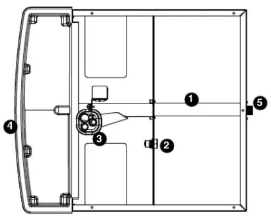
TOP VIEW
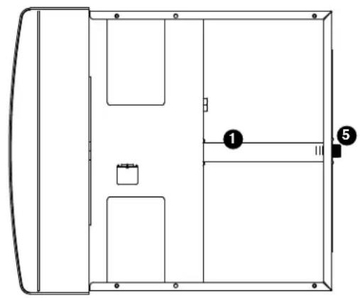
natural_image
Technical line drawing of a mechanical or architectural component with labeled parts (1, 5), no readable text or symbols beyond labelsBOTTOM VIEW
| Reference Description Part # | |
| Not shown Valve, water shut-off 01035526 | |
| 1 Drain tube assembly 01074285 | |
| 2 Fitting, water inlet 01065275 | |
| 3 Cup, cleaning 01065226 | |
| 4 Drain pan 502705 | |
| 5 Fitting, drain 00109728 | |
| Not shown Tee, water inlet, 1/4" 502923 | |
| Not shown Grille, drain pan | 502706 |
Solenoid dispense assembly
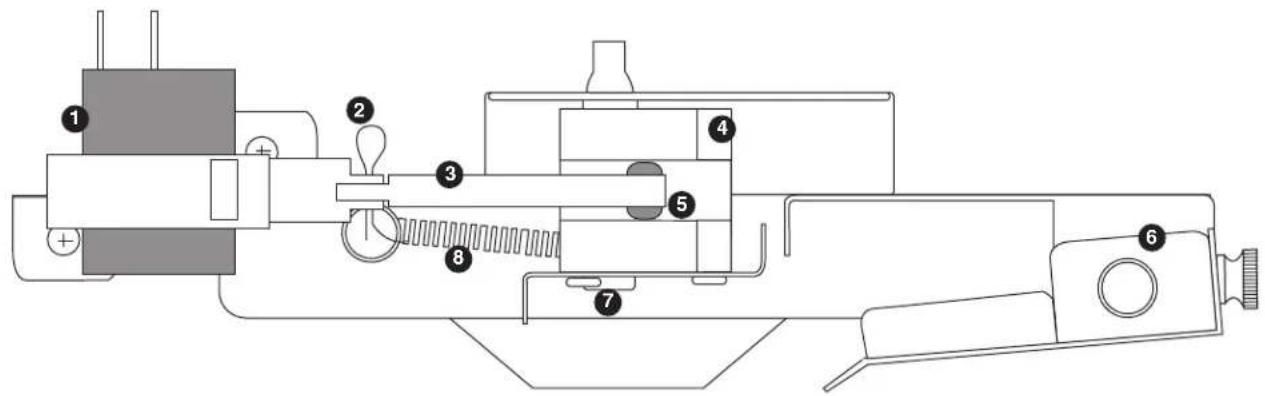
| Reference # Description Part # | ||
| 1 Solenoid, dispense 501830 | ||
| 2 Cotter pin 502040 | ||
| 3 Linkage, solenoid (includes 502054 grommet) 502039 | ||
| 4 Block, dispense gate 502042 | ||
| 5 Grommet 502054 | ||
| 6 Splash pan, gate assembly 502045 | ||
| 7 Shoulder screw and washer 502038 | ||
| 8 Spring, gate assembly 501824 | ||
| — | Gate assembly, 115V (includes reference numbers 1 through 8 above) | 502043 |
| Reference # | Description Part # | |
| Standard capacity filter system | ||
| Not shown Follett QC4-FL4S water filter system (includes FL4S primary cartridge and head, coarse pre-filter and head, pressure gauge, flushing valve; assembled and installed on mounting bracket), one per ice machine | 00130229 | |
| Not shown Follett FL4S primary replacement cartridge 00130245 | ||
| Not shown Water filter cartridge - primary, carton of 6 00954297 | ||
| Not shown Everpure coarse pre-filter cartridge 00130211 | ||
| Not shown Water pre-filter cartridge - pre-filter, carton of 12 00954305 | ||
| High capacity filter system | ||
| Not shown High capacity water filter system (one per ice machine) 00978957 | ||
| Not shown High capacity water filter cartridge - primary, single 00978965 | ||
| Not shown High capacity water filter cartridge - primary, carton of 6 00978973 | ||
| Not shown Water pre-filter cartridge - pre-filter, single 00130211 | ||
| Not shown Water pre-filter cartridge - pre-filter, carton of 12 00954305 | ||
| Carbonless high capacity filter system | ||
| Not shown Carbonless high capacity water filter system (one per ice machine) - HorizonTM and MaestroPlus series ice machines | 01050442 | |
| Not shown Carbonless high capacity water filter cartridge - primary, single | 01050426 | |
| Not shown Carbonless high capacity water filter cartridge - primary, carton of 6 | 01050434 | |
| Not shown Water pre-filter cartridge - pre-filter, single 00130211 | ||
| Not shown Water pre-filter cartridge - pre-filter, carton of 12 00954305 | ||
| Other filtration | ||
| Not shown Claris hardness removal filtration system | 00986059 | |
| Not shown Replacement filter for Claris system | 00985127 | |
| Not shown Reverse osmosis system, 200 gallons per day | 00986034 | |
| Not shown Replacement reverse osmosis cartridge | 00985085 | |
| Not shown Replacement reverse osmosis pre-filter | 00985077 | |
| Not shown Cleaning plug for reverse osmosis system | 00985119 | |
| Not shown Cleaning cartridge for reverse osmosis system | 00985101 | |
| Water pressure | ||
| Not shown Water pressure regulator (25 psi) | 501781 | |
| Cleaning/Sanitizing | ||
| Not shown SafeCLEAN ice machine cleaner, carton of 24 x 7 oz packets | 00132001 | |
| Not shown Sponge, sanitary | 00131524 | |
| Not shown IMS-II sanitizing concentrate | ||
SafeCLEAN, SensorSAFE, Maestro Plus, Symphony Plus, Quiet Night and Sani-Sponge are trademarks of Follett Corporation.
Follett and RIDE are registered trademarks of Follett Corporation, registered in US.
- Symphony Plus™ 110 Series Ice and Water Dispensers
- Contents
- Welcome to Follett. 3
- Specifications 4
- Installation....5
- User information 12
- Cleaning/descaling and sanitizing 12
- Service 18
- Dispenser troubleshooting 20
- Disassembly and replacement instructions.... 22
- Replacement parts 26
- Water treatment accessories for Symphony Plus ice and water dispensers.... 35
- Welcome to Follett
- Before you begin
- 110CT425A-L
- CAUTION!
- Specifications
- Electrical
- Ambient
- Plumbing
- Ventilation clearances
- Approximate shipping weight
- Installation
- Installing freestanding dispensers
- Installing countertop dispensers
- For utilities exiting through bottom only:
- Installing RIDE ice machines
- User information
- How the dispenser works
- How SensorSAFE infrared dispensing works
- Quiet Night™/Sleep cycle (does not apply to CR units)
- Cleaning/descaling and sanitizing
- Weekly
- Dispenser drain pan and drain line
- Splash panel front, SensorSAFE infrared dispensing
- Monthly
- Condenser (air-cooled ice machine only)
- Semi-Annually (more often if conditions dictate)
- Cleaning & Sanitizing Tool Checklist
- Ice Machine and Dispenser
- Cleaning/Descaling Procedure
- Sanitizing Procedure
- Dispenser only
- Sanitize dispenser
- Service
- Wiring diagram
- Lever models
- SensorSAFE models
- Before calling for service
- Board guide
- Lens/sensor troubleshooting
- Dispense chute removal
- Dispense wheel and drive bar removal
- Drive bar removal
- Wheelmotor removal
- Ice transport tube replacement – Top mount units
- Ice transport tube replacement – Freestanding and RIDE models
- Steps 7-8 for units with RIDE ice machines only
- All units
- Thermostat replacement
- Dispenser exterior
- Electrical components
Brand : Follett
Model : 110CT425A-L
Category : Sorbet maker