
RP4.2-MB11 - Car audio interface PAC - Free user manual and instructions
Find the device manual for free RP4.2-MB11 PAC in PDF.


| Product Type | Vehicle Radio Replacement Interface |
| Brand | PAC |
| Model | RP4.2-MB11 |
| Compatible Vehicles | 2014-2016 Mercedes Sprinter with factory radio |
| Dimensions (approx) | 4 x 2 x 1 inches |
| Weight (approx) | 0.2 lb |
| Power Supply | 12V DC (vehicle battery), Accessory output: 10A max |
| Main Functions | Retain steering wheel controls (SWC) and reverse camera; provide retained accessory power (RAP), vehicle speed signal (VSS), illumination, reverse, parking brake outputs; support short press/long press dual command; compatible with VS41 for additional cameras |
| Radio Compatibility | Alpine, JVC, Kenwood, Clarion, Pioneer, Sony, Fusion, and others (Advent, BOYO, Dual, Lightning Audio, Rockford Fosgate, Visteon) |
| Wiring Connections | Interface Connector 1 (Red: accessory, Yellow: constant 12V, Black: ground); Interface Connector 2 (3.5mm SWC, Pink: MS-CAN+, Pink/Black: MS-CAN-, Blue/Yellow: SWC, Orange/White: illumination, Pink: VSS, Violet/White: reverse, Light Green: parking brake); Vehicle Connector (speaker wires, power antenna) |
| Installation Requirements | Set DIP switches according to radio brand before connecting; wire per connection chart; connect SWC to aftermarket radio; optional VS41 connection for cameras |
| Programming | Optional: press programming button, press SWC button, release within 1.5s for short press or hold until LED blinks for long press |
| Maintenance and Cleaning | Keep dry; avoid moisture; clean with soft dry cloth; no liquid cleaners |
| Safety Precautions | Disconnect vehicle battery before installation; avoid short circuits; ensure proper wire gauge |
| Spare Parts and Repairability | No user-serviceable parts; contact PAC for replacements or support |
| General Information | Designed for seamless integration; retains factory features; supports aftermarket radio upgrade |
Frequently Asked Questions - RP4.2-MB11 PAC
User questions about RP4.2-MB11 PAC
0 question about this device. Answer the ones you know or ask your own.
Ask a new question about this device
Download the instructions for your Car audio interface in PDF format for free! Find your manual RP4.2-MB11 - PAC and take your electronic device back in hand. On this page are published all the documents necessary for the use of your device. RP4.2-MB11 by PAC.
USER MANUAL RP4.2-MB11 PAC
Introduction & Features
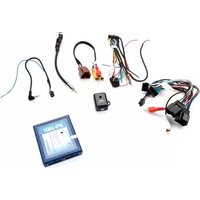
The RP4.2-MB11 interface allows the replacement of a factory radio in a 2014 - 2016 Mercedes Sprinter vehicle equipped with a factory radio. Using this interface will retain the factory steering wheel controls (SWC) and reverse camera. Use of this interface also allows you to program two radio functions to each SWC button by using short press long press dual command functionality. The RP4.2-MB11 also provides data bus driven outputs such as retained accessory power (RAP), vehicle speed signal (VSS), illumination, reverse and parking brake.
Important Notes
- The RP4.2-MB11 is ONLY compatible with the 2014 - 2016 Mercedes Sprinter vehicle when the vehicle is equipped with a factory radio. Vehicles equipped with the radio delete package will need to use the RP4.2-MB21.
- The VS41 can be connected to the RP4.2-MB11 to add left, right and front camera inputs. When the VS41 is connected, the RP4.2-MB11 will send the proper signals to the VS41 so that the left and right cameras are triggered when the turn signals are active. The front camera can be triggered by using the supplied 3-way toggle switch.
- The front camera, when triggered via the supplied 3-way toggle switch, will only be active at speeds below 6 mph.
Wiring Connection Chart
Interface Connector 1
| Red | Accessory Output (10 amp) |
| Yellow 12v+ | Constant |
| Black Ground | |
Interface Connector 2
| 3.5mm Jack | Steering Wheel Control Output |
| Pink | MS-CAN + Input |
| Pink / Black | MS-CAN - Input |
| Blue / Yellow | Steering Wheel Control Output |
| Orange / White | Illumination Output |
| Pink | Vehicle Speed Signal Output |
| Violet / White | Reverse Output |
| Light Green | Parking Brake Output (-) |
Vehicle Connector
| Yellow +12v | Constant |
| Black Ground | |
| Blue Powered Antenna Turn On | |
| White Front | Left + input |
| White / Black Front Left - input | |
| Grey Front | Right + input |
| Grey / Black Front Right - input | |
| Green Rear | Left + input |
| Green / Black Rear Left - input | |
| Purple Rear | Right + input |
| Purple / Black | Rear Right - input |
Module Layout
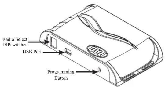

Installation Steps

SET RADIO DIPSWITCHES (ON = DOWN)
| Alpine JV | C Kenwood Cl | larion Pioneer | / Other Sony | Fusion | ||
| None 1 2 | 1 & 2 3 1 & 3 | 2 | & 3 |
Other = Advent, BOYO, Dual, Lightning Audio, Rockford Fosgate, Visteon
-
The radio select DIP switches on the side of the interface must be adjusted to the proper radio setting before plugging the interface into the vehicle.
-
Make all connections as described in the connection chart on the previous page.
- Connect the SWC wire or 3.5mm jack to the aftermarket radio (aftermarket radio must support a wired remote input).
- If using the VS41, connect the 10-pin connector from the VS41-HAR to the RP4.2-MB11's expansion port.
- If using the VS41, connect the cameras to the proper inputs on the VS41-HAR.
- Mount the supplied 3-way switch, which will force both the front camera (when using the VS41) and rear camera, where it is easily accessible.
- The blind spot cameras will be activated with the use of the turn signal stalk. The passenger side camera will be active when the right turn signal is active. The driver side camera will be active when the left turn signal is active. If more control is needed to activate the side cameras, simply flip DIP Switch 4 down (ON). With DIP Switch 4 on it will require a double tap of the turn signal within 2 seconds to activate either the right or left camera. The turn signal will need to remain in the on position for the camera to remain active.
- Once the DIP Switches have been set and all connections have been made, plug the interface into the vehicle.
- If you wish to reassign functions to the SWC, or utilize short press long press dual command functionality follow the optional programming instructions on the next page.
Module Wiring Overview

Steering Wheel Controls
Default Steering Wheel Control Programming
IMPORTANT! The interface comes pre-programmed for all of the vehicle's factory SWC functions and does not require programming unless you wish to re-assign the SWC functions, or utilize short press long press dual command functionality. The SWC can always be restored to default settings by pressing and releasing the program button on the side of the interface once then wait 7 seconds for the LED to flash 3 times.
Default SWC Button Assignments
| Alpine JVC Kenwood Clarion Pioneer / Other Sony Fusion | |||||||
| Volume + | Volume + | Volume + | Volume + | Volume + | Volume + | Volume + | Volume + |
| Volume - | Volume - | Volume - | Volume - | Volume - | Volume - | Volume - | Volume - |
| Arrow Up | Track + | Track + | Track + | Track + | Track + | Track + | Track + |
| Arrow Down | Track - | Track - | Track - | Track - | Track - | Track - | Track - |
| Answer | Receive | Receive | Off Hook | Send | Answer | Answer | Power |
| End | End | Reject | On Hook | End | End | Reject/Source | N/P |

natural_image
Circular black button with four directional arrows and document icons on the central circle (no text or symbols)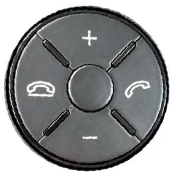
natural_image
Circular mechanical component with four arms and a central hub, featuring a plus sign and two curved gauges (no text or symbols)Optional Steering Wheel Control Programming
If you wish to re-assign the SWC functions, or utilize short press long press dual command functionality, the interface must be programmed in the specific order shown in the chart on page 3. If you come across a function in the chart that your steering wheel does not have, or you do not want to program, press and release the programming button on the side of the interface to skip that function. The LED will flash off and on confirming that you have successfully skipped that function and are ready to proceed to the next one.
Short Press Long Press Dual Command Functionality
This feature allows you to assign two aftermarket radio functions to each of the vehicle's SWC buttons. It can be used with as many of the buttons as the user likes, or none at all. When this functionality is implemented, quickly pressing and releasing a SWC button will initiate the short press command, while pressing and holding a SWC button for longer than two seconds will initiate the long press command. Please note that no long press commands are programmed by default. If you wish to assign dual command functionality to the SWC please follow the programming steps on the next page.
Steering Wheel Controls (cont.)
Optional SWC Programming Procedure
- Turn the key to the ignition position.
- Put the Driver Information Center (DIC) in the vehicle's instrument cluster into the Audio or Telephone mode using the Page Up or Page Down buttons on the steering wheel. Failure to do this will not allow the Arrow Up and Arrow Down buttons to be programmed.
- Press and release programming button on the side of the interface. The Status LED will turn green.
- Within 7 seconds, press the button that is to be learned on the steering wheel. The LED will turn red when the button is pressed.
At this point you have two options:
A. For short press functionality: Release the button within 1.5 seconds. The LED will turn back on.
B. For long press functionality: Hold the button until the LED starts blinking. Release the button and the LED will go back to solid green.
- If you need to program more buttons, repeat step 3 for each additional audio function on the steering wheel.
- If you come across a function in the chart that your steering wheel does not have, or you do not want to program, press and release the program button on the side of the interface to skip that function.
- Once programming is completed, wait seven seconds. The LED will flash three times indicating end of programming.
- Test the interface for proper functionality. Whenever a SWC button is pressed the LED on the interface should blink. If any function does not work, repeat the programming steps.
Optional Programming Order
| Alpine JVC Kenwood Clarion | Other ■ | Pioneer Sony | Fusion | |||||
| 1 | Volume + | Volume + | Volume + | Volume + | Volume + | Volume + | Volume + | Volume + |
| 2 | Volume - | Volume - | Volume - | Volume - | Volume - | Volume - | Volume - | Volume - |
| 3 | Mute | Mute | Mute | Mute | Mute | Mute | Mute | Mute |
| 4 | Preset + | Source | Source | Source | Preset + | Preset + | Preset + | Source |
| 5 | Preset - | Track + | Play | Search + | Preset - | Preset - | Preset - | Track + |
| 6 | Source | Track - | Track + | Search - | Source | Source | Source | Track - |
| 7 | Track + | Band / Disc + | Track - | Band | Track + | Track + | Track + | Audio |
| 8 | Track - | Preset / Disc - | Disc / FM + | Send / End | Track - | Track - | Track - | Power |
| 9 | Power | Select | Disc / AM - | Send | Band | Band | Band | |
| 10 | Enter / Play | Attenuation Answer End | Answer 📋 | Phone Menu | Reject Call / Source (Bluetooth equipped radios only) | |||
| 11 | Band / Program | Phone Receive | Voice Dial | End 📋 | Answer Call | Answer / End Call | ||
| 12 | Receive | Phone Reject | On Hook | PTT 📋 | End Call | |||
| 13 | End | Voice Dial | Off Hook | VR | ||||
| 14 | VR | Power | Mute (Multimedia units only) | |||||
| 15 | Preset + | |||||||
| - Advent, Boyo, Dual, Lightning Audio, Jensen, Rockford Fosgate & Visteon - Jensen & Advent ONLY | ||||||||
Testing and Verification
- Turn the key to the ignition position. The LED on the interface will turn on & the +12v accessory wire will turn on.
- Turn on the radio and check balance and fade.
- Verify that all SWCs are functioning properly. The LED will flash whenever a SWC button is pressed, even if a function is not assigned to the button.
- Verify that all data driven navigation outputs are functioning properly.
- When using the VS41 to add left, right, front and rear cameras, be sure to trigger them with either the turn signals or the supplied switch and ensure proper operation.
- The LED and radio will turn off when the ignition is turned off.
- Introduction & Features
- Important Notes
- Wiring Connection Chart
- Module Layout
- Installation Steps
- Module Wiring Overview
- Steering Wheel Controls
- Default Steering Wheel Control Programming
- Optional Steering Wheel Control Programming
- Short Press Long Press Dual Command Functionality
- Steering Wheel Controls (cont.)
- Optional SWC Programming Procedure
- At this point you have two options:
- Testing and Verification
Brand : PAC
Model : RP4.2-MB11
Category : Car audio interface