TG9387 - Door handle Dormakaba - Free user manual and instructions
Find the device manual for free TG9387 Dormakaba in PDF.


| Brand | Dormakaba |
| Model | TG9387 |
| Product Type | Electronic Door Lock |
| Dimensions (L x W x H) | Approx. 6.5 x 3.0 x 1.5 in (165 x 76 x 38 mm) |
| Weight | Approx. 2.2 lbs (1.0 kg) |
| Power Supply | 4 x AA alkaline batteries (6V DC) |
| Battery Life | Up to 1 year under normal use |
| Low Battery Warning | Audible and visual indicator |
| Key Override | Mechanical key override included |
| Access Methods | PIN code, RFID card, mechanical key |
| User Capacity | Up to 100 PIN codes and 50 RFID cards |
| Operating Temperature | 14°F to 122°F (-10°C to 50°C) |
| Durability | IP54 rated (dust and splash resistant) |
| Installation | Standard door preparation for mortise or cylindrical locks |
| Material | Zinc alloy and stainless steel |
| Security Features | Anti-tamper alarm, auto-lock, keypad lockout after wrong attempts |
| Maintenance | Clean with dry cloth; avoid harsh chemicals |
| Spare Parts | Batteries, screws, strike plate, and mechanical key available |
| Repair | Repairable by certified technicians; modular design |
| Warranty | Limited 2-year warranty |
| Certifications | UL, FCC, ANSI Grade 2 |
Frequently Asked Questions - TG9387 Dormakaba
User questions about TG9387 Dormakaba
0 question about this device. Answer the ones you know or ask your own.
Ask a new question about this device
Download the instructions for your Door handle in PDF format for free! Find your manual TG9387 - Dormakaba and take your electronic device back in hand. On this page are published all the documents necessary for the use of your device. TG9387 by Dormakaba.
USER MANUAL TG9387 Dormakaba
natural_image
Simple line drawing of two vertical posts with circular connectors, no text or symbols presentTG 9387 Non-locking Ladder Pulls
Back-to-back and Single-sided
Installation instructions
905381 - 08-2021
| EN |
dormakaba
Table of contents
1 Technical specifications 3
1.1 Overview 3
1.1.1 General information 3
1.1.2 Intended use 3
1.1.3 Glass requirements/fittings/mounting 3
1.1.4 Requirements for glass panel 3
1.1.5 Safety instructions 3
1.1.6 Symbols used - Safety/Installation 3
1.1.7 Maintenance, care, repair 3
1.1.8 Disposal 3
2 Installation Instructions Glass Door: B2B non-locking ladder pulls 4
2.1 Assemble outside pull 4
2.2 Assemble inside pull 5
3 Installation Instructions Glass Door: Single-sided non-locking ladder pulls 6
3.1 Assemble inside pull (with rose) 6
4 Installation Instructions Wood Door: B2B non-locking pull 7
4.1 Assemble outside pull 7
4.2 Assemble inside pull 8
5 Installation Instructions Wood Door: Single-sided non-locking pull (with rose) 9
5.1 Assemble inside pull (with rose) 9
6 Installation Instructions Wood Door: Single-sided non-locking pull (without rose) 10
6.1 Assemble inside pull (without rose) 10
1 Technical specifications
1.1 Overview
These instructions are for installation of TG 9387 Back-to-Back and Single-Sided Non-Locking Ladder Pulls for the following mounting and style versions:
1. Glass mount
1.1.1 General information
- dormakaba requires use of tempered laminated or tempered monolithic glass.
- dormakaba glass hardware is not suitable for harsh environment; for example, applications where chemicals (e.g. chlorine) are used such as indoor swimming pools, saunas, or salt-water pools.
- Never move sliding panels faster than walking speed and always stop the door manually before it reaches end position.
- Do not swing/slide doors with excessive force. Ensure proper installation of limiting stop to prevent door from opening too far.
1.1.2 Intended use
- For swinging/sliding doors in dry indoor areas only.
- For manual slow opening and closing only.
1.1.3 Glass requirements/fittings/mounting
- Fasteners must be sufficiently dimensioned for the substructure/wall and weight of the door.
- When adjusting glass components, always stick to the required clearance for the respective hardware. Adjust clearance so glass does not come in contact with any hard surfaces such as glass, metal or concrete.
- Do not use excessive force when installing the glass (avoid over tightening screws.)
1.1.4 Requirements for glass panel
- dormakaba requires use of fully tempered glass, which complies with ASTM C 1036 and ASTM C 1048. Secondary heat soaking processes are recommended but not required. This applies to both tempered monolithic and tempered laminated glass.
- Clamping area must be flat and uncoated (no self-cleaning coating!)
- Never use glass with conchoidal fractures and/or damaged edges.
1.1.5 Safety instructions
• Always wear protective clothing.
- Only properly qualified and specially trained staff are authorized to mount dormakaba glass hardware.
- Due to crushing hazards and possible injury caused by breakage of glass during mounting, corresponding protective clothing (especially gloves and protective goggles) is required.
- Never clamp metal fitting hardware directly to glass surface.
1.1.6 Symbols used - Safety/Installation

CAUTION
Mounting components must meet the requirements of substructure/wall and door weight. Please read the technical information for fittings.

WARNING
Risk of breaking glass. When installing the door, support the door panel with a block of wood or similar object.

CLOSING EDGE OF DOOR
1.1.7 Maintenance, care, repair
- Immediately replace damaged parts.
• Always use original dormakaba parts. - Clean clamping area with alcohol-based standard commercial cleaning agent before mounting the glass hardware.
- Use a damp cloth for occasional cleaning.
• Always use silicone - and oil-free cleaners (e.g. acetone). - Check glass hardware at regular intervals for proper positioning, smooth operation and correct adjustment.
- High traffic door systems require inspection by properly qualified staff (specialized companies or installation firms.)
1.1.8 Disposal
Disposal in accordance with local, state and national regulations.
2 Installation Instructions Glass Door: B2B non-locking ladder pulls
2.1 Assemble outside pull
Fig 1

PULLS FOR GLASS
NOTE: Be sure to use the appropriately sized screw pack dependent upon the size and type of door being used.
2.1.1 Thread the following parts into the threaded stud:
- threaded anchor (reference part number 905.390)
• clear plastic washer (qty: 1 per post) - black plastic washer
- spacer
2.1.2 Insert the anchor and parts into the outside pull posts.
2.1.3 Tighten the set screw on each post of the outside pull.
2.2 Assemble inside pull
Fig 2

2.2.1 Place the outside pull through the door.
NOTE: BE SURE TO SUPPORT THE PULL IN THE DOOR WITH YOUR HAND.
2.2.2 To secure the posts, thread the following parts onto the threaded stud:
- black plastic washer
- clear plastic washer
- threaded anchor
2.2.3 Slide the inside pull onto the anchors.
2.2.4 Tighten the set screw on each post of the inside pull.
3 Installation Instructions Glass Door: Single-sided non-locking ladder pulls
3.1 Assemble inside pull (with rose)
Fig 3
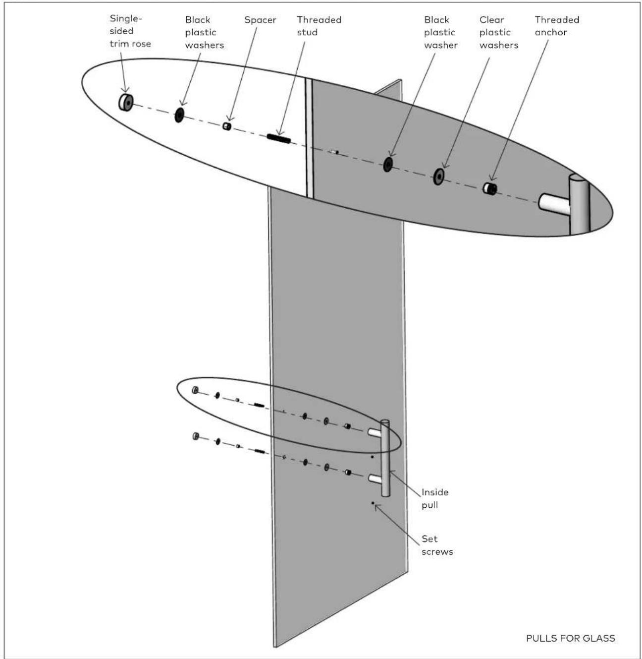
3.1.1 Lay the ladder pull on a flat surface.
3.1.2 Thread the following parts into each other:
- single-sided trim rose
- clear plastic washer
- threaded stud
- spacer
3.1.3 Feed the stud, spacer and rose assemblies through the glass door.
3.1.4 To secure the post, thread the following parts onto the threaded stud:
- clear plastic washer
- black plastic washer
- threaded anchor
NOTE: The tapered side of the anchor should face the pull.
3.1.5 Slide the inside pull onto the anchors.
3.1.6 Tighten the set screw on each post of the inside pull.
4 Installation Instructions Wood Door: B2B non-locking pull
4.1 Assemble outside pull
Fig 4

PULLS FOR WOOD
NOTE: Be sure to use the appropriately sized screw pack dependent upon the size and type of door being used.
4.1.1 Thread the following part into the threaded stud:
• threaded anchor
4.2 Assemble inside pull
Fig 5

4.2.1 Place the outside pull through the door.
NOTE: BE SURE TO SUPPORT THE PULL IN THE DOOR WITH YOUR HAND.
4.2.2 To secure the posts, thread the following part onto the threaded stud:
- threaded anchor
4.2.3 Slide the inside pull onto the anchors.
4.2.4 Tighten the set screw on each post of the inside pull.
5 Installation Instructions Wood Door: Single-sided non-locking pull (with rose)
5.1 Assemble inside pull (with rose)
Fig 6
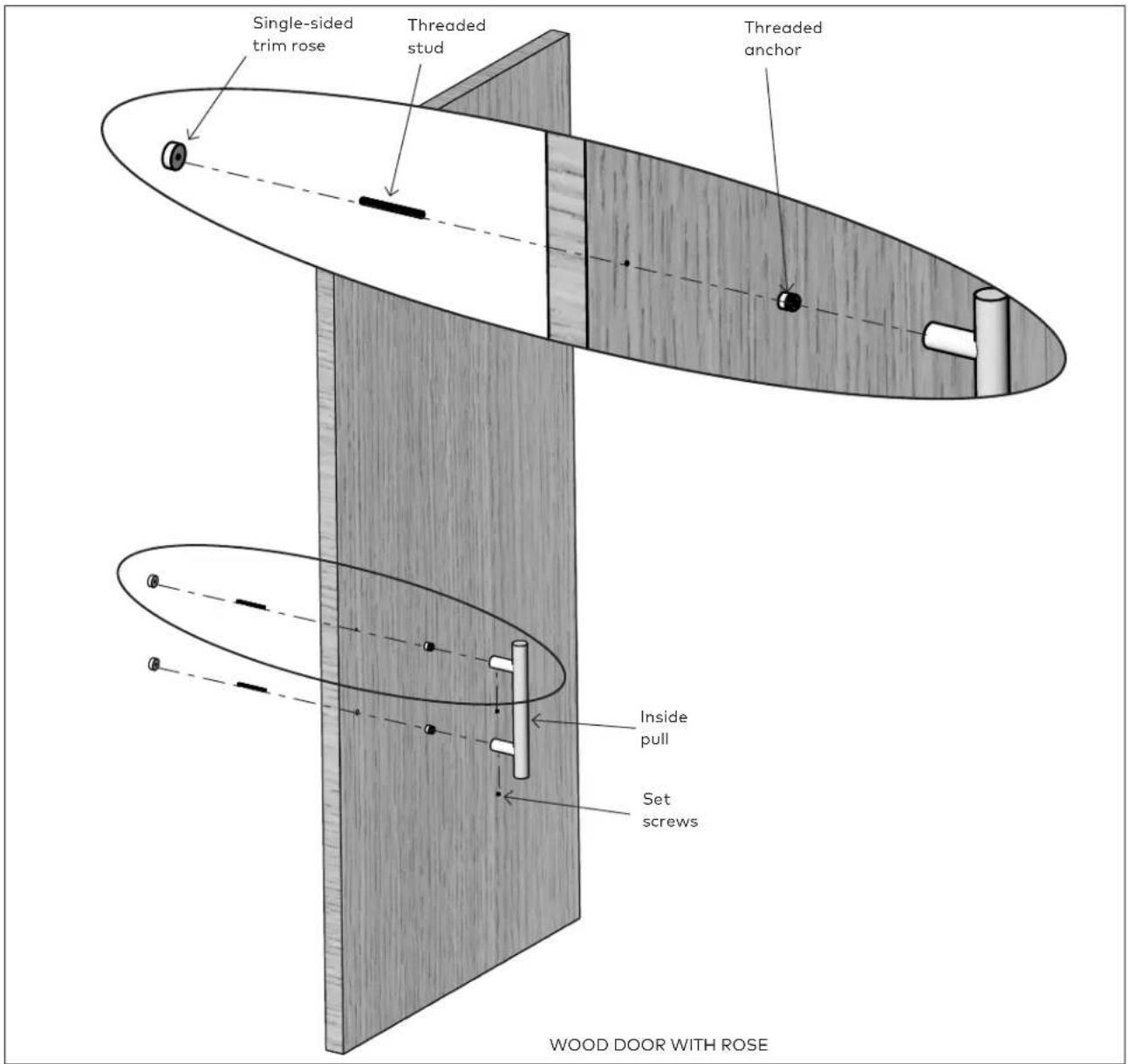
5.1.1 Lay the ladder pull on a flat surface.
5.1.2 Thread the following parts into each other:
- single-sided trim rose
- threaded stud
5.1.3 Feed the rose and stud through the wood door.
5.1.4 To secure the post, thread the following parts onto the threaded stud:
- threaded anchor
NOTE: The tapered side of the anchor should face the pull.
5.1.5 Slide the inside pull onto the anchors.
5.1.6 Tighten the set screw on each post of the inside pull.
6 Installation Instructions Wood Door: Single-sided non-locking pull (without rose)
6.1 Assemble inside pull (without rose)
Fig 7

6.1.1 Lay the ladder pull on a flat surface.
6.1.2 Thread the following parts into each other:
- blind fastener
- threaded anchor
NOTE: The tapered side of the anchor should face the pull.
6.1.3 Twist the blind fastener through pilot hole in the wood door.
6.1.4 Slide the inside pull onto the anchors.
6.1.5 Tighten the set screw on each post of the inside pull.
- TG 9387 Non-locking Ladder Pulls
- Table of contents
- Technical specifications 3
- Installation Instructions Glass Door: B2B non-locking ladder pulls 4
- Installation Instructions Glass Door: Single-sided non-locking ladder pulls 6
- Installation Instructions Wood Door: B2B non-locking pull 7
- Installation Instructions Wood Door: Single-sided non-locking pull (with rose) 9
- Installation Instructions Wood Door: Single-sided non-locking pull (without rose) 10
- Technical specifications
- Overview
- Glass mount
- General information
- Intended use
- Glass requirements/fittings/mounting
- Requirements for glass panel
- Safety instructions
- Symbols used - Safety/Installation
- CAUTION
- WARNING
- CLOSING EDGE OF DOOR
- Maintenance, care, repair
- Disposal
- Installation Instructions Glass Door: B2B non-locking ladder pulls
- Assemble outside pull
- Assemble inside pull
- Installation Instructions Glass Door: Single-sided non-locking ladder pulls
- Assemble inside pull (with rose)
- Installation Instructions Wood Door: B2B non-locking pull
- Assemble outside pull
- Assemble inside pull
- Installation Instructions Wood Door: Single-sided non-locking pull (with rose)
- Assemble inside pull (with rose)
- NOTE: The tapered side of the anchor should face the pull.
- Installation Instructions Wood Door: Single-sided non-locking pull (without rose)
- Assemble inside pull (without rose)
Brand : Dormakaba
Model : TG9387
Category : Door handle